

Enerpac PL User Manual [en, de, es, fr, it]

PRODUCTION AUTOMATION
L2057 Rev. O 1/96
CONTENTS
Instruction Sheet
®
Pull Cylinders -- Metric
ENGLISH .... ....... ............. ......... ....... ....1 - 8
DEUTSCH......................... ................12-15
FRANCAIS.......... .. ... .. ... .. .... . .... . .. .... . .16-19
IMPORTANT RECEIVING INSTRUCTIONS
Visually inspect all compone nts for shipping damage . If any shipping damage is found,
notify carrier at once. Shipping damage is
responsible fo r all repair or replacement cos t resulting from damage in shipment.
DESCRIPTIO N
These pull cylinders are designed to push/pull in a straight direction with no
side loading. Single- and double-acting models are available in most c apac i ties. Plunger
bolts are not supplied with cylinders. Plunger bolts must be quality Gra de 8
(8.8 DIN 912).
ESPAÑOL.................... ............ .........20-23
ITALIANO ................... ................. ....24-27
NEDERLANDS...... . ..........................28-31
NOT covered by warranty. The carrier is
Upper Flange Lower Flange Threaded Body
Model Number Code
1 2 3 4 5 6 optional
P = pull
cylinder
T = threaded body
U = upper flange
L = lower flange
S = straight S = single-acting
D = double-acting
2 = 2,2 kN
5 = 5,6 kN
9 = 9,0 kN
35 = 35,0 kN
2 = metric V = Viton

SPECIFICATIONS
Capacity [kN (lbs.)]
Body Style
Cylinder Type
Hydraulic Stroke
[mm (in.)]
Effective Area
2
[cm
(in2 )]
Oil Capacity
3
[cm
(in3 )]
Max. Pressure
[bar (psi)]
Max. Flow at 350 bar (5000 psi)
3
[cm
/min (in.3/min)]
clamp/
unclamp
clamp
unclamp
clamp
unclamp
PRELIMINARY INFORMATION
IMPORTANT: Failure to read and follow these instructions may lead to
system malfunction or pr oduct failure, and could invalidate your wa rranty.
Cylinder Specifications
-22 Series -52 Series -92 Series -352 Series
2,2 (500) 5,6 (1250) 9,0 (2000) 35,0 (7900)
threaded body, lower flange, or upper flange mounting
single-acting and double-acting double-act ing double-a cting
16,7 (0.658) 23,0 (0.906) 22,0 (.867) 30,0 (1.182)
0,75 (0.116) 1,79 (0.278) 3,13 (0.485) 12,42 (1.925)
1,54 (0.238) 3,80 (0.589) 8, 04 (1.246) 23,76 (3.683)
1,25 (0.076) 4,12 (0.251) 6,88 (0.420) 37,20 (2.269)
2,57 (0.157) 8,74 (0.533) 17,69 (1.079) 71,28 (4.348)
350 bar (5000 psi)
393 (24) 820 (50) 122 (2000) 7867 (480)
(1)Hi gh flow rates can lead to excessive cylinder speed which can cause cylinder damage.
Hydraulic pressure and cyli n der speed must be adjusted to match the parti cular
cylinder. The push/pull force also varies wit h the system pressure. Refer to the
operating specifications above.
(2)Flow controls with return checks may be required to reduce pull cyli n der speed to the
recommended rate. The return checks help minimize back pressure that could l e ad to
an unclamp malfunction on single-acting systems.
(3)When using single-acting pull cylinders, limit the return flow back pre ssure to
3,45 bar (50 psi) maximum. Large diameter tubing (10 mm O.D. or larger) and f low
controls with free flow return checks help minimize back pr essure. Consult Enerpac for
proper system design.
2
MOUNTING SPECIFICATIONS
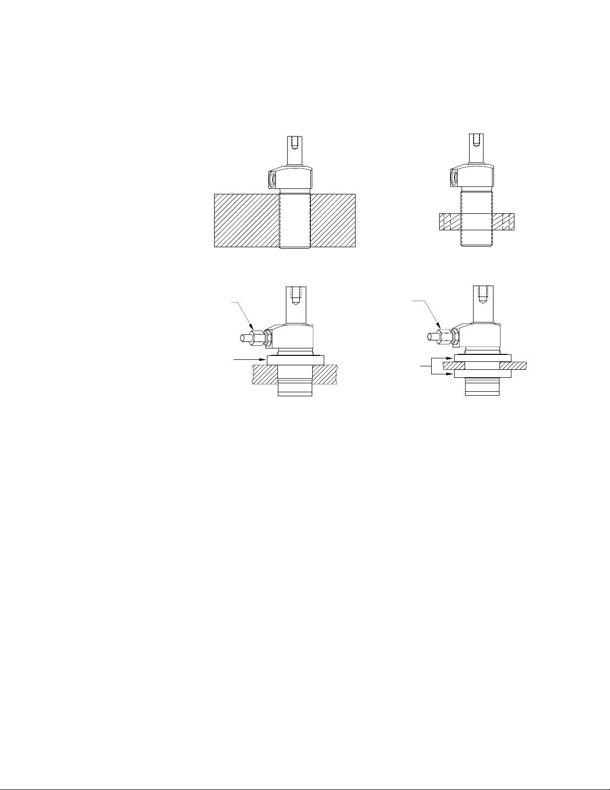
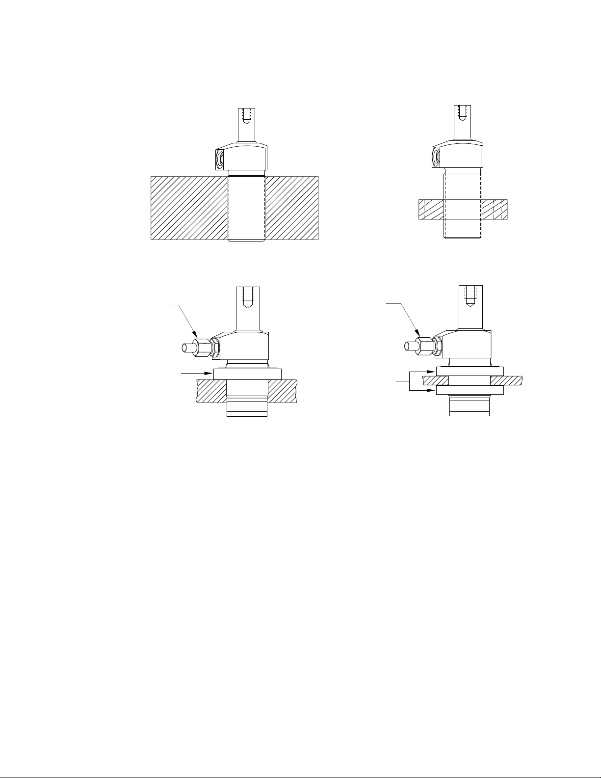
Mounting Threaded Body Cylinder s
Threaded body cylinders can be threaded into a tapped hole, s ecured to the fixture using
a mounting flange, threaded into the fixture and secured with a jam nut, or mounted
through a c learance hole and secured with jam nuts. See illustrations below.
threaded into fixture
mounting flange
oil connection
jam nut
oil connection
jam nuts
Figure 1
When a threaded body pull cylinder is being installed in a fixture, the thread engagement
should be no less than the thread engagement f or the standard Enerpac mounting flange.
If a cylinder is being mounted using just the lower portion of the threads , the engagement
should be increased f o r additional support. See table below for minimum thread
engagement.
Cylinder Capacity Minimum Thread Engagement
2,2 kN 500 lb 13 mm .50"
5,6 kN 1250 lb 13 mm .50"
9 kN 2000 lb 16 mm .63"
35 kN 7900 lb 30 mm 1.25"
3
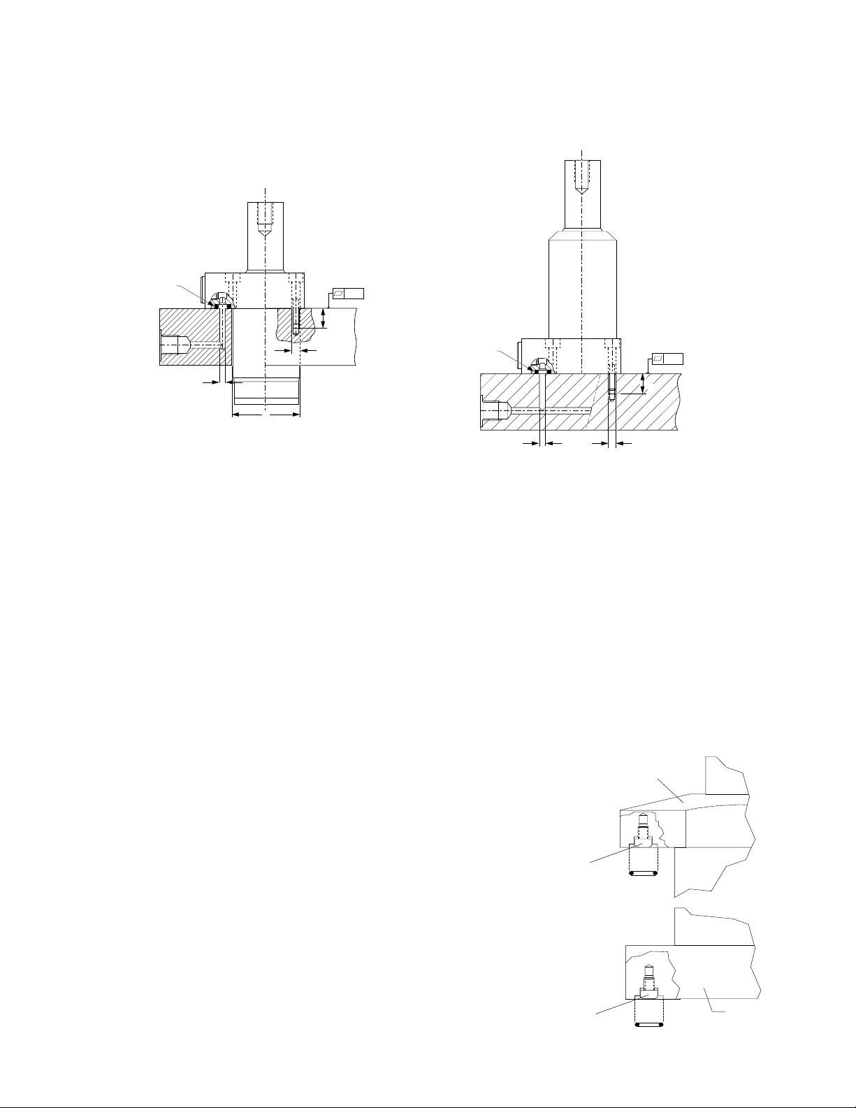
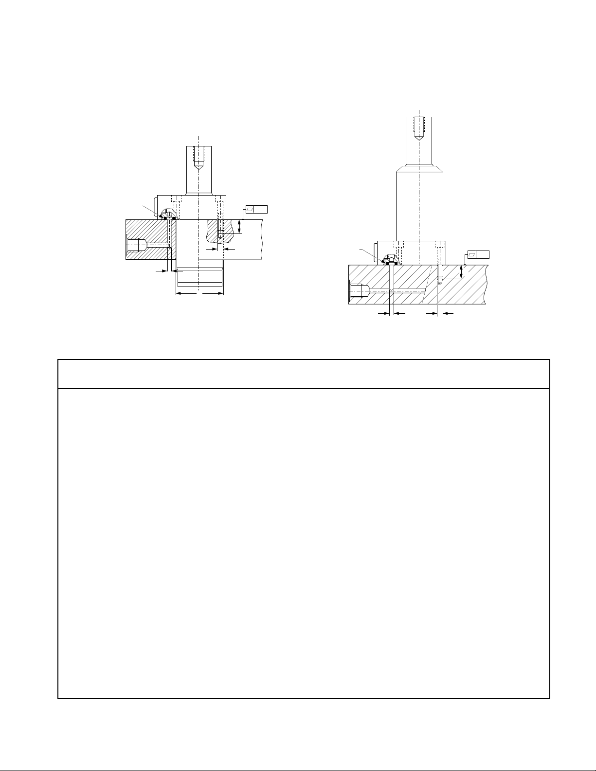
Mou ntin g Upp er and Lower Fl ange Cylinders
A WARNING
The fi xture must be capable of withstanding 350 bar (5000 psi ) hydraulic
working pressure when cylinders are manifold mounted.
Manifold
O-ring
Cylinder
Capacity
2,2 kN
500 lb
5,6 kN
1250 lb
9 kN
2000 lb
A
Max. Oil
Channel
Diameter
B
Ø A
4mm
0.156"
4mm
0.156"
4mm
0.156"
0.003
0,1
D
C
Manifold Specifications
Fixture
Hole Diameter
Ø B
29,2 ± 0,8
1.15 ±.03
36,0 ± 0,8
1.42 ± .03
49,1 ± 0,8
1.93 ± .03
Figure 2
Mounting
Threads
C
M5 15 mm
M6 15 mm
M6 15 mm
Manifold
O-ring
A
Minimum
Thread
Depth
D
0.59"
0.59"
0.59"
Lubricated
Mounting Bolt
Torque
4,5-5 ,4 Nm
40-48 in-lbs.
12,2-14,9 Nm
9-11 ft-lbs.
13,5-15 Nm
10-11 ft-lbs.
0.003
0,1
D
C
Manifold
O-Ring
Dimensions
I.D. x w.
6,07 x 1,78 mm
0.239 x 0.070"
7,65 x 1,78 mm
0.301 x 0.070"
4,34 x 3,53 mm
0.171 x 0.139
35 kN
7900 lb
4mm
0.156"
77,5 0,3
3.05 ± .01
M10 15 mm
Before manifold mounting the pull c ylinder, remove
the port screw plugs and copper ga ske ts or o-rings.
Prior to mounting and bolting down the pull cylinder,
lubricate the o-rings provided and install them in the
counter-bore around the port.
Be sure that the o-ring does not get pinched or
damaged during mounting as leakage c ould result. T o
prevent leakage from the manifold mounting, provide
a fixture mounting surface with flatness within 0.08
mm (0.003 in.) and a surface roughness not to exc eed
Ra 1, 6.
4
0.59"
65-7 2 Nm
48-53 ft-lbs.
Remove port
screw plug.
Remove port
screw plug.
4,34 x 3,53 mm
.171 x .139"
Upper Flange
o-ring
o-ring
Lower
Flange
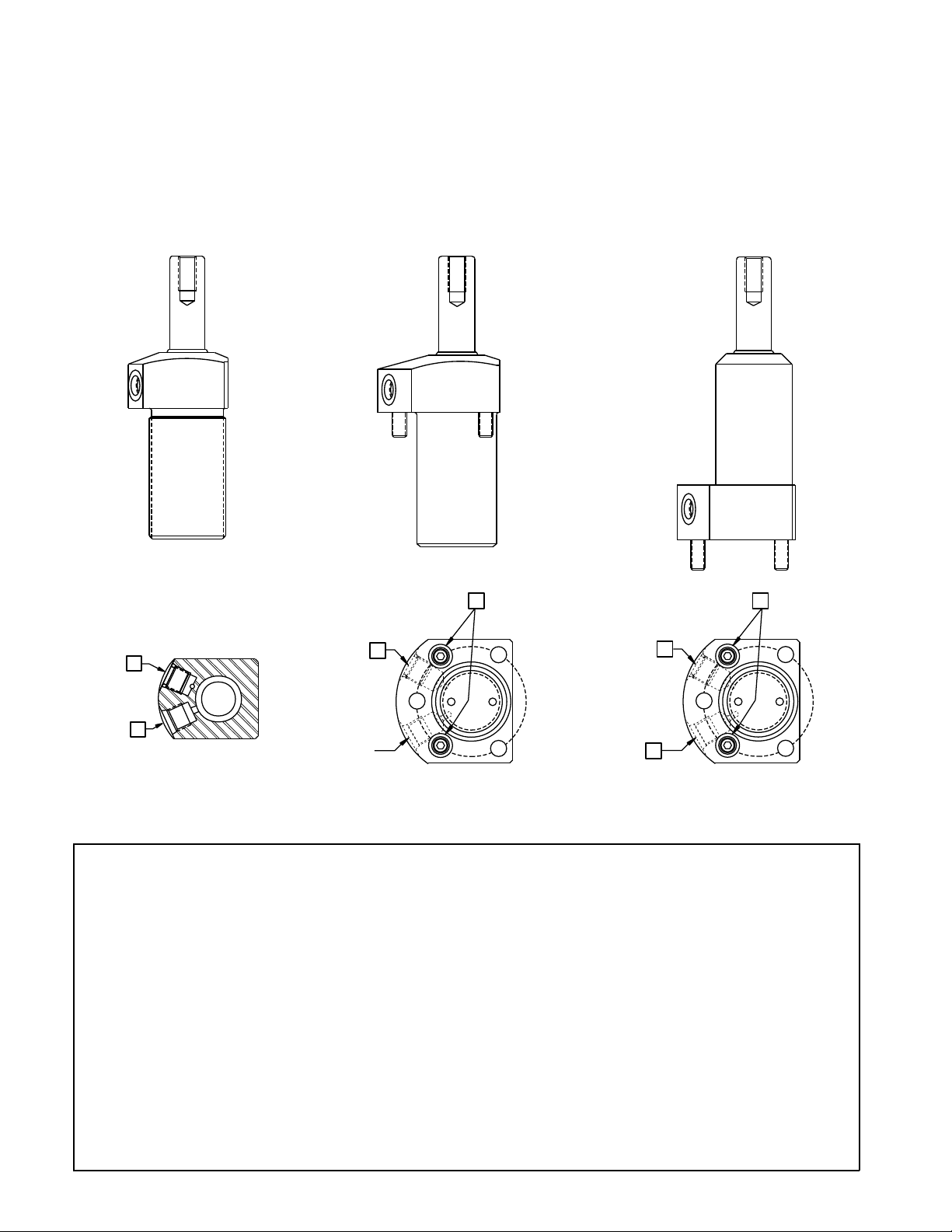
INSTALLATION
Hydraulic Connect ions
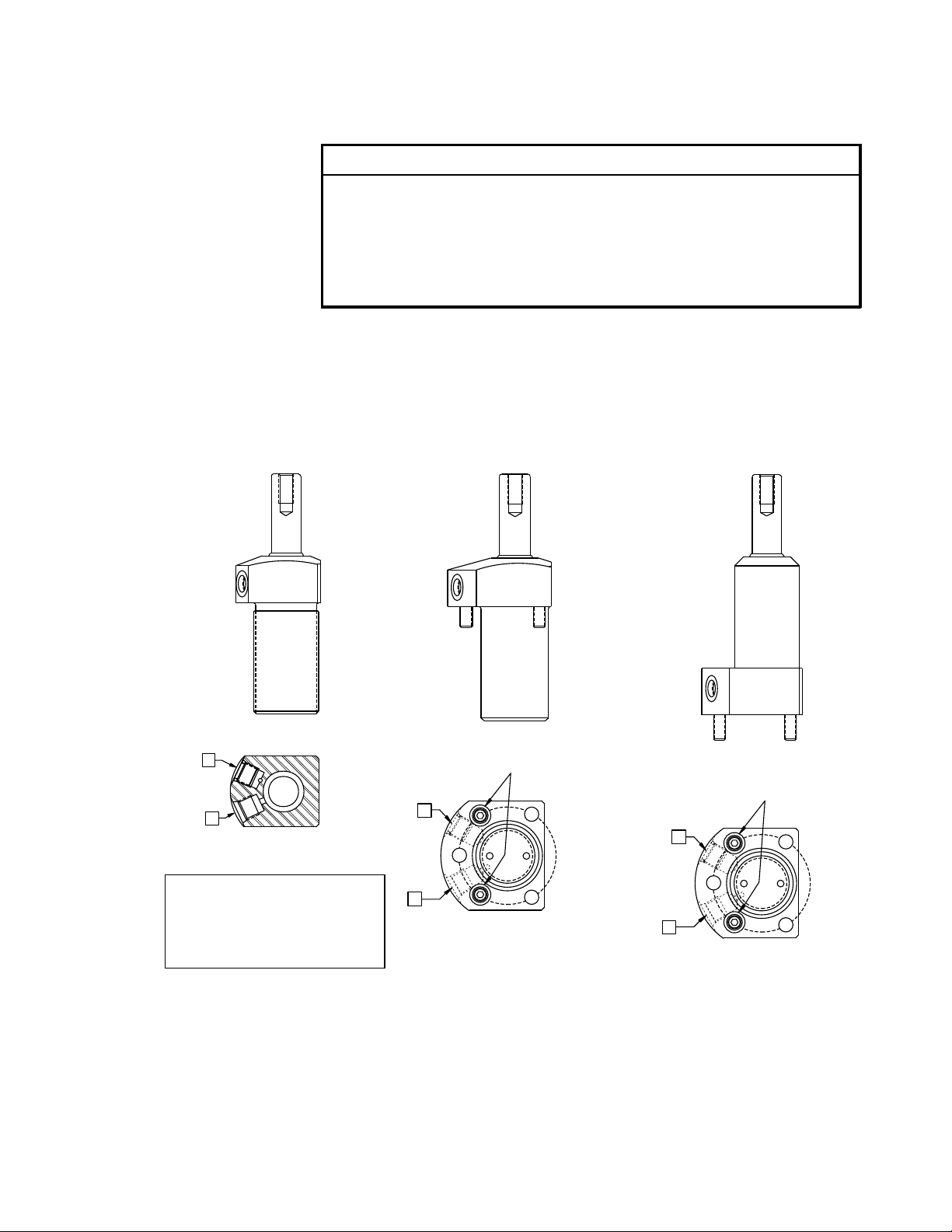
Port Identification
To make port connections, install fittings rated for 5000 psi (350 bar).
Cylinder Ports
Cylinder Capacity 350 bar (5000 psi) Fitting
2,2 kN (500 lbs.)
5,6 kN (1250 lbs.)
9 kN ( 2000 lbs.)
35 kN (7900 lbs.)
1
/8 BSPP
1
/8 BSPP
1
/4 BSPP
1
/4 BSPP
DO NOT us e thread seala nt. Sealing is accomplis hed by using an o-ring on the fitting
boss. Lubricate the o-ring prior to assembly.
NOTE: When designing your hydraulic circuit, cons ider the factors listed in
PRELIMINARY INFORMATION on p age 2. For mo re informa tion about plumbing
hydraulic circuits, see your Enerpac Production Automation Catalog.
Threaded
Body Style
Side View
A
B
Bottom View
KEY
A: Clamp Port
B: Vent Port (Single-acting Models)
Unclamp Port (Double-acting Models)
NOTE: Do not remove vent plug except
to attach tubing (See vent plug section).
OPERATI ON
Upper Flange
Body Style
A
B
Bottom View
Lower Flange
Body Style
Side View
Side View
Manifold Ports
Manifold Ports
A
B
Bottom View
A CAUT ION
—To ensure maximum cylinder performance and safety; be sure all hydraulic
connections, hoses, and fit tin gs are properl y sealed and fully tightened.
—Be sure al l items are rated to withstan d system pr essures. Under-rated
components will not wit hstand higher pressure. Using under-rated
components will lead t o equipment damage and possible personal i njury.
5
Vent Plug
Single-acting cylinders have a vented plug on the left side of the cylinder when you a re
facing the hydraulic ports. To prevent entry of chips and coolant, the vent plug must not
be removed. If the vent plug is subjec ted to a continuous coolant flood c ondition, attac h
tubing to the port using a BSPP fitting and run the tubing to a non-contaminated area o f
the fixture.
Pressure and Flow Settings
A CAUTION
It i s very i mportant that you use the correct pressure and flow setti ngs.
Operating outside these limits will cause damage to the cylinder. Damage
caused by exceeding rated pressur e and maximum flow is NOT COVERED BY
WARRANTY.
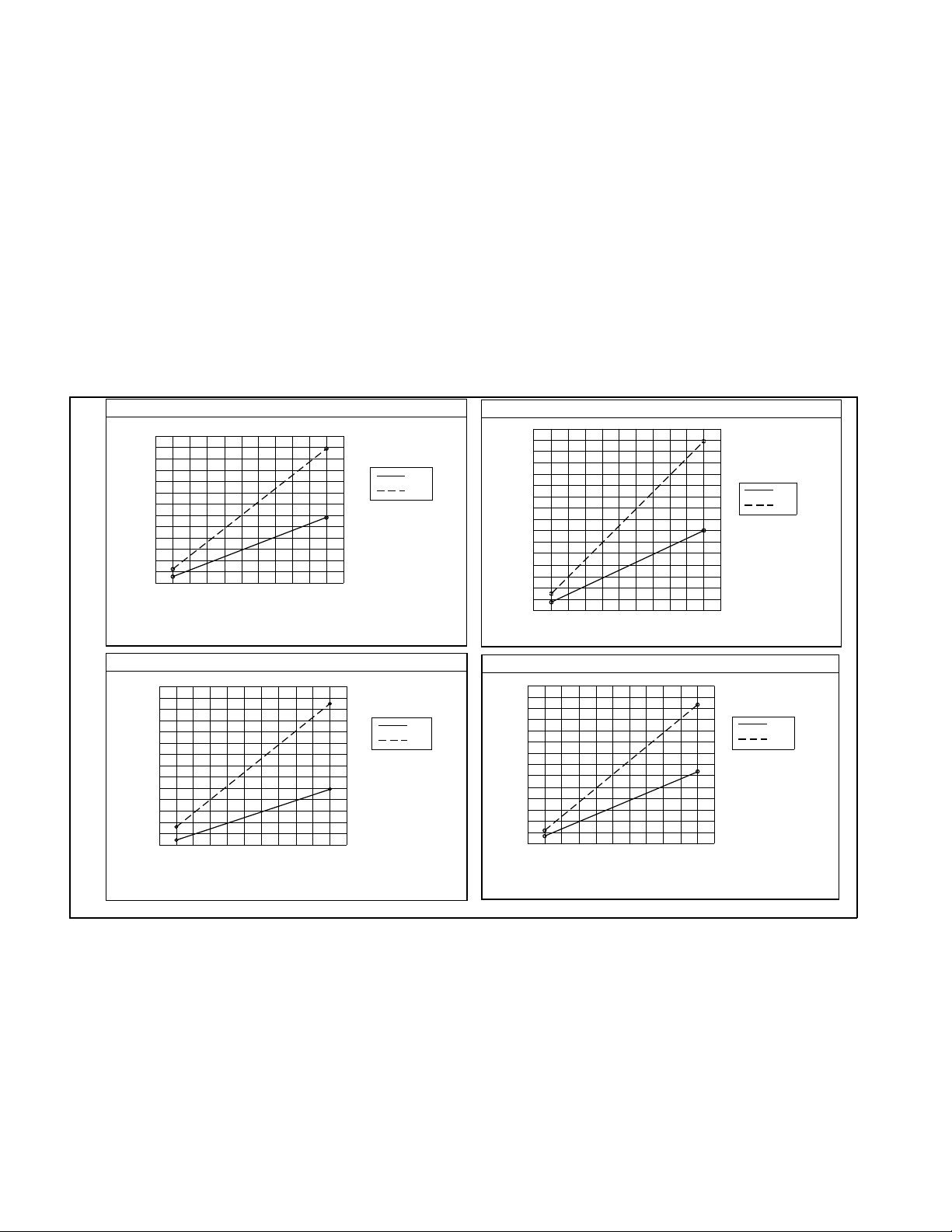
Push/Pull Fo rce s vs. Syste m Pressure
NOTE: Push forces are for double-acting cylinders only.
2,2 kN [500 lbs.]
4,9
[1100]
4,0
[900]
3,1
[700]
2,2
[500]
1,3
Force kN [lbs.]
[300]
0,4
[100]
0
[1000]
206,8
137,968,9
[3000][2000] [4000]
Pressure bar [psi]
275,8
344,7
[5000]
Pull Force:
Push Force:
Stroke
Pull
Push
0,75 x pressure
1,54 X pressure
13,3
[3000]
11,6
[2600]
9,8
[2200]
8,0
[1800]
6,2
Force kN [lbs.]
[1400]
4,5
[1000]
2,7
[600]
0,9
[200]
137,968,9
[1000]0[2000]
Pressure bar [psi]
5,6 kN [1250 lbs.]
206,8 275,8
[3000] [4000]
344,7
[5000]
Stroke
Pull Force:
Push Force:
Pull
Push
1,79 x pressure
3,80 x pressure
26,7
[6000]
22,2
[5000]
17,8
[4000]
13,3
[3000]
Force kN [lbs.]
8,9
[2000]
4,4
[1000]
137,968,9
[1000]0[2000]
Pressure bar [psi]
MAINTENANCE
9,0 kN [2000 lbs.]
206,8 275,8
[3000] [4000]
344,7
[5000]
Stroke
Pull Force:
Push Force:
Pull
Push
3,13 x pressure
8,04 x pressure
86,7
[19500]
73,4
[16500]
60,0
[13500]
46,7
[10500]
33,3
[7500]
Force kN [lbs.]
20,0
[4500]
6,7
[1500]
0
68,9
[1000]
35,0 kN [7900 lbs.]
137,9
[2000]
[3000] [4000]
Pressure bar [psi]
Stroke
Pull Force: 12,42 x pressure
Push Force: 23,76 x pressure
344,7206,8 275,8
[5000]
Pull
Push
Figure 3
Maintenance is required when wear or lea kage is noticed. Oc casionally inspec t all
components to detect any problem requiring s ervice and maintena nce. Enerpac offers
ready-to-us e Repair Parts Kits. Repair Parts Sheets are available with assembly drawing
and parts list. Contact Enerpac.
IMPORTANT: Consult the Repair Parts Sheet for se rvice information as to correct
assembling and disasse mbling. Incorrect maintenance and servic e such as wrong torque
values may cause product malfunctions a nd/or personal injury.
6

TROUBLESHOOTING
The following information is inte nded to be used only as an aid in determining if a
problem exists. For repair s ervice, contact your Distributor or Authorized Enerpac
Service Center.
Problem Possible Cause Solution
1. Cylinder will not
clamp/unclamp.
2. Cylinder
advances
part way.
3. Cylinder
clamps/unclamps
slower than
norma l.
4. Cylinder
clamps/unclamps
but will not hold
pressure.
5. Cylinder leaks
oil.
A.pump release valve open
B.no oil in pump re servoir
C.air in syste m
D.couplers not fully tightened
E.blocked hydraulic line
F. spring broken in c ylinder
A.oil level in pump too low
B.plunge r binding
A.leaking connection
B.restricted hydraulic line
C.pump malfunction
A.seals damaged
B.leaking connection
C.pump malfunction
A.seals damaged
B.plunge r worn or damaged
A.close pump release valve
B.fill pump reservoir
C.remove air from hydraulic system
D.re-tighten couplers
E.check valves, fittings, and tubing
F.replace spring
A.fill pump reservoir
B. replace damaged parts
—refer to Repair Parts Sheet
A.re-tighten fittings, couplers, and tubing
B. check valves, fittings, and tubing
C.refer to pump Instruction Sheet
A.replace seals
—refer to Repair Parts Sheet
B.re-tighten fittings, couplers, and tubing
C.refe r to pump Instr uction Sheet
A.replace seals
—refer to Repair Parts Sheet
B. replace damaged parts
—refer to Repair Parts Sheet
7
Mont age von Zyl in dern mit Auß engewinde
Montage des Vérin s à Corps Fileté
Montaje de Cilindros de Cuerp o Roscado
Montaggio dei Cilindri a Corpo Filettato,
Monteren van cilinders met Schroefdraadlichaam
threaded into fixture
oil connection
C
jam nut
Abbil dung, Figure, Ilustració n, Fig ura, Afbeelding, 1
A
mounting flange
oil connection
D
C
jam nuts
D
B
AB C
In die Vorrichtung
geschraubt
vérin vissé sur la machine bride de fixation raccord d’huile écrou de
atorinil lado en el apar ejo brida de montaje conexión de aceite contratuerca (contratuercas)
avvitato nel supporto fisso flangia di montaggio raccordo del olio controdado (controdadi)
in appendage geschroefd montageflens oileaansluiting tegenmoer (tegenmoeren)
Montageflansch Ölanschluß Gegenmutter
blocage
(écrous de blocage)
D
(Gegenmuttern)
écrou de blocage
8
Montage vo n Kopf- und Fußflanschzylind ern
Montage des Vérins Par Bride Supérieure ou Inférieure
Montaje de Cilindros Con Brida Superior y Brida Inferior
Mont aggio dei Cilindri a Flangia Superio re ed Inf eriore
Monteren van Onder- en Bovenflens van Cilinders
Manifold
Especificaciones del colector,Specifiche del collettore, Specificaties verdeelstuk
Zylinderkapazität
Capacité du
vérin
Capacidad
del cilindro
Forza
sviluppata
dal cilindro
Cilinder-
capaciteit
E
O-ring
Max. Ölkanal-
durchmesser
Diamètre maxi.
du passage
d’huile
Diámetro máx.
de conducto
de aceite
Diametro max.
condotto olio
Max. diameter
oliekanaal
0.003
0,1
D
C
A
B
Manifold
O-ring
E
A
0.003
0,1
D
C
Abbil dung, Figure, Ilustració n, Fig ura, Afbeelding, 2
Anschlußspezifikatio nen, Carac téristi ques du bloc foré,
Durchmesser
der Öffnung
Diamètre
du trou
de la machine
Diámetro de
agujero en
aparejo
Diametro foro
supporto fisso
Diameter gat
appendage
Ø A Ø B C D E
Befestigungs-
gewinde
Filets de
montage
Roscas de
montaje
Filetti di
montaggio
Montage-
schroefdraad
Mindest-
Einschraubtiefe
Profondeur
minimum
Profundidad
mín. de rocas
Profunditá
min. dei filetti
Minimale
scroefdraad-
diepte
Anzug-Dreh-
moment der
Befestigungs-
schrauben
(geschmiert)
Couple de
serrage du
boulon de
montage
lubrifié
Apriete de
pernos de
montaje
lubricatos
Coppia di
montaggio
bullone
lubrificato
Aandraai-
moment
gesmeerde
montagebaut
O-Ring-Anschluß
Innendurch-
messer x B
Dimensions du
joint torique
D.I. x I.
Dimensiones de
anillo "O"
de colector
D. I. x ancho
Dimensioni
O-Ring
collettore
D.I. x s
Afmeting
O-Ring
verdeelstuk
binnendiam. x b
2,2 kN 4 mm 29,2 ± 0,8 M5 15 mm 4,5-5,4 Nm 6,07 x 1,78 mm
5,6 kN 4mm 36,0 ± 0,8 M6 15 mm 12,2-14,9 Nm 7,65 x 1,78 mm
9 kN 4mm 49,1 ± 0,8 M6 15 mm 13,5-15 Nm 4,34 x 3,53 mm
35 kN 4mm 77,5 ± 0,3 M10 15 mm 65-72 Nm 4,34 x 3,53 mm
9
Anschlußbeschreibung
Identific ation d’oriface
Identificación de Lumbreras
Identificazione degli Attacchi
Identificatie Poorten
Zylinder mit Außengewinde
Corps fileté
Cuerpo roscado
Corpo filettato
Schroefdraadlichaam
Seitenansicht, Vue de côté, Vista lateral, Vista laterale, Zijaanzicht
Zylinder mit Kopfflansch
Corps á bride supérieure
Cuerpo con brida superior
Corpo a flangia superiore
Lichaam met bovenflens
C C
Zylinder mit Fußflansch
Corps á bride inférieure
Cuerpo con brida inferior
Corpo flangia inferiore
Lichaam met onderflens
A
A
B
B
Ansicht von unten, Vue de dessous, Vista inferior, Vista dal basso, Onderaanzicht
A
B
Abbildung, Figure, Ilustració n, Figura, Afbeelding, 3
AB C
Spannenanschluß Entlüftungsanschluß (einfach wirkende Modelle)
Entspannungsanschluß (doppelt wirkende Modelle)
oriface de bridage oriface d’aération (modèles simple effe t)
oriface de débridage (modèel es double effet)
Lumbrera de fijición Lumbrera de ventilación (modelos de acción única )
Lumbrera de soltado (modelos de acción doble)
attacco di serraggio attacco di sfiato (modelli a dffetto semplice)
attacco di rilascio (modelli a doppio effetto)
Klempoort Ontluchtingspoort (enkelwerkende modellen)
Afspanpoort (dubbelwerkende modellen)
HINWEISE: Den Entlüftungsstopfen nicht entfernen, es sei denn zum Anschließen von Rohren. (Siehe den Abschnitt Entlüftungsstopfen.)
REMARQU E: Ne pas retirer le bouchon à é vent, sauf pour brancher la conduite. (Voir la section bouchon à évent.)
NOTA: No saque el tapón ventilado sakvi oara c ibectar tybería en su lugar (vea la sección Tapón ventilado).
NOTA: non rimuovere il tappo di sfiato, fuorché per il collegamento di tubi (vedere la sezione sul tappo di dfiato).
N.B . : Verwijder de ontluchtingsstop alleen voor het bevestigen van slangen. (Zie het gedeelte Ontluchtingsstop).
Verteilerkopfanschlüsse
Orifaces du bloc foré
Lumbreras del colector
Attacchi del collettore
Porten verdeelstuk
10
 Loading...