

Page 1
Instruction Sheet
Hydraulic Hand Pumps
POWERFUL SOLUTIONS. GLOBAL FORCE.
L1763 Rev I 03/09
Repair Parts Sheets for this product are available
from the Enerpac web site at www.enerpac.com, or
from your nearest Authorized Enerpac Service Center
or Enerpac Sales office.
1.0 IMPORTANT RECEIVING
INSTRUCTIONS
Visually inspect all components for shipping damage.
Shipping damage is not covered by warranty. If
shipping damage is found, notify carrier at once. The
carrier is responsible for all repair and replacement
costs resulting from damage in shipment.
SAFETY FIRST
2.0 SAFETY ISSUES
Read all instructions,
warnings and cautions
carefully. Follow all safety
precautions to avoid personal injury or property
damage during system operation. Enerpac cannot be
responsible for damage or injury resulting from unsafe
product use, lack of maintenance or incorrect product
and/or system operation. Contact Enerpac when in
doubt as to the safety precautions and operations. If
you have never been trained on high-pressure
hydraulic safety, consult your distribution or service
center for a free Enerpac Hydraulic safety course.
Failure to comply with the following cautions and
warnings could cause equipment damage and
personal injury.
A CAUTION is used to indicate correct operating or
maintenance procedures and practices to prevent
damage to, or destruction of equipment or other
property.
A WARNING indicates a potential danger that
requires correct procedures or practices to avoid
personal injury.
A DANGER is only used when your action or lack of
action may cause serious injury or even death.
WARNING: Wear proper personal
protective gear when operating hydraulic
equipment.
WARNING: Stay clear of loads supported
by hydraulics. A cylinder, when used as a
load lifting device, should never be used
as a load holding device. After the load
has been raised or lowered, it must always be
blocked mechanically.
WARNING: USE ONLY RIGID PIECES
TO HOLD LOADS. Carefully select steel
or wood blocks that are capable of
supporting the load. Never use a hydraulic cylinder
as a shim or spacer in any lifting or pressing
application.
DANGER: To avoid personal injury
keep hands and feet away from cylinder
and workpiece during operation.
WARNING: Do not exceed equipment
ratings. Never attempt to lift a load
weighing more than the capacity of the
cylinder. Overloading causes equipment
failure and possible personal injury. The cylinders are
designed for a max. pressure of 700 bar [10,000 psi].
Do not connect a jack or cylinder to a pump with a
higher pressure rating.
DANGER: Never set the relief valve to a
higher pressure than the maximum rated
pressure of the pump. Higher settings
may result in equipment damage and/or
personal injury. Do not remove relief valve.
WARNING: The system operating
pressure must not exceed the pressure
rating of the lowest rated component in
the system. Install pressure gauges in the
system to monitor operating pressure. It is your
window to what is happening in the system.
CAUTION: Avoid damaging hydraulic
hose. Avoid sharp bends and kinks when
routing hydraulic hoses. Using a bent or
kinked hose will cause severe backpressure. Sharp bends and kinks will internally
damage the hose leading to premature hose failure.
Do not drop heavy objects on hose. A
sharp impact may cause internal damage
to hose wire strands. Applying pressure to
a damaged hose may cause it to rupture.
Index:
English ..................................................................1-7
Français ............................................................. 8-14
Deutsch............................................................ 15-22
Italiano ............................................................. 23-29
Español ............................................................ 30-36
Nederlands....................................................... 37-44
Portuguese....................................................... 45-51
........................................................... 52-58
...............................................................59-64
Svenska.............................................................
65-71
Greek.................................................................
72-80
Finnish...............................................................
81-87
Russian..............................................................
88-95
Page 2
2
IMPORTANT: Do not lift hydraulic
equipment by the hoses or swivel
couplers. Use the carrying handle or other
means of safe transport.
CAUTION: Keep hydraulic equipment
away from flames and heat. Excessive
heat will soften packings and seals,
resulting in fluid leaks. Heat also weakens
hose materials and packings. For optimum
performance do not expose equipment to
temperatures of 65 °C [150 °F] or higher. Protect
hoses and cylinders from weld spatter.
DANGER: Do not handle pressurized
hoses. Escaping oil under pressure can
penetrate the skin, causing serious injury.
If oil is injected under the skin, see a doctor
immediately.
WARNING: Only use hydraulic cylinders in
a coupled system. Never use a cylinder
with unconnected couplers. If the cylinder
becomes extremely overloaded,
components can fail catastrophically causing severe
personal injury.
WARNING: BE SURE SETUP IS STABLE
BEFORE LIFTING LOAD. Cylinders
should be placed on a flat surface that can
support the load. Where applicable, use a
cylinder base for added stability. Do not
weld or otherwise modify the cylinder to attach a
base or other support.
Avoid situations where loads are not
directly centered on the cylinder plunger.
Off-center loads produce considerable
strain on cylinders and plungers. In
addition, the load may slip or fall, causing potentially
dangerous results.
Distribute the load evenly across the entire
saddle surface. Always use a saddle to
protect the plunger.
IMPORTANT: Hydraulic equipment must
only be serviced by a qualified hydraulic
technician. For repair service, contact the
Authorized ENERPAC Service Center in
your area. To protect your warranty, use only
ENERPAC oil.
WARNING: Immediately replace worn or
damaged parts by genuine ENERPAC
parts. Standard grade parts will break
causing personal injury and property
damage. ENERPAC parts are designed to fit properly
and withstand high loads.
CAUTION: Always use the handle to carry
the pump. Carrying the pump by the hose
may damage the hose and/or the pump.
SPECIFICATIONS – Use this instruction sheet for the following hand pump models.
Hand Pump Specifications
Model Type Maximum Pressure Oil Volume per Stroke Usable Oil Capacity
(Speed) Rating psi [bar] in3[cm3]in
3
[cm3]
EHF-65 1 6,500 [440] .16 [2.62] 22 [360]
P-18 1 2,850 [200] .16 [2.62] 22 [360]
P-25 1 2,500 [170] .58 [9.51] 231 [3786]
P-39, 1003 1 10,000 [700] .16 [2.62] 43 [705]
P-50 1 5,000 [340] .29 [4.75] 231 [3786]
P-51 1 3,000 [210] .25 [4.09] 50 [820]
P-141, 1001 1 10,000 [700] .055 [.90] 20 [328]
P-391, 1004 1 10,000 [700] .151 [2.47] 55 [900]
Stage 1 Stage 2 Stage 1 Stage 2
P-80, 1006 2 350 [25] 10,000 [700] .99 [16.23] .15 [2.46] 140 [2295]
P-84 2 350 [25] 10,000 [700] .99 [16.23] .15 [2.46] 140 [2295]
P-142, 1002 2 200 [14] 10,000 [700] .221 [3.62] .055 [.90] 20 [328]
P-142AL 2 200 [14] 10,000 [700] .221 [3.62] .055 [.90] 9.0 [148]
P-202 2 200 [14] 10,000 [700] .221 [3.62] .055 [.90] 55 [900]
P-77 2 200 [14] 10,000 [700] .63 [16.0] .094 [2.41] 47 [769]
P-392, 1005 2 200 [14] 10,000 [700] .687 [11.26] .151 [2.47] 55 [900]
P-392AL 2 200 [14] 10,000 [700] .687 [11.26] .151 [2.47] 55 [900]
P-462 2 200 [14] 10,000 [700] 7.69 [126.00] .29 [4.75] 462 [7572]
P-464 2 200 [14] 10,000 [700] 7.69 [126.00] .29 [4.75] 462 [7572]
P-801 2 350 [25] 10,000 [700] .99 [16.23] .15 [2.46] 250 [4095]
P-802 2 400 [28] 10,000 [700] 2.40 [39.34] .15 [2.46] 155 [2540]
P-842 2 400 [28] 10,000 [700] 2.40 [39.34] .15 [2.46] 155 [2540]
Page 3
3.0 DESCRIPTION
3.1 Models P-141, 1001; P-142, 1002;
P-202; P-391, 1004; P-392, 1005; P-802;
P-842
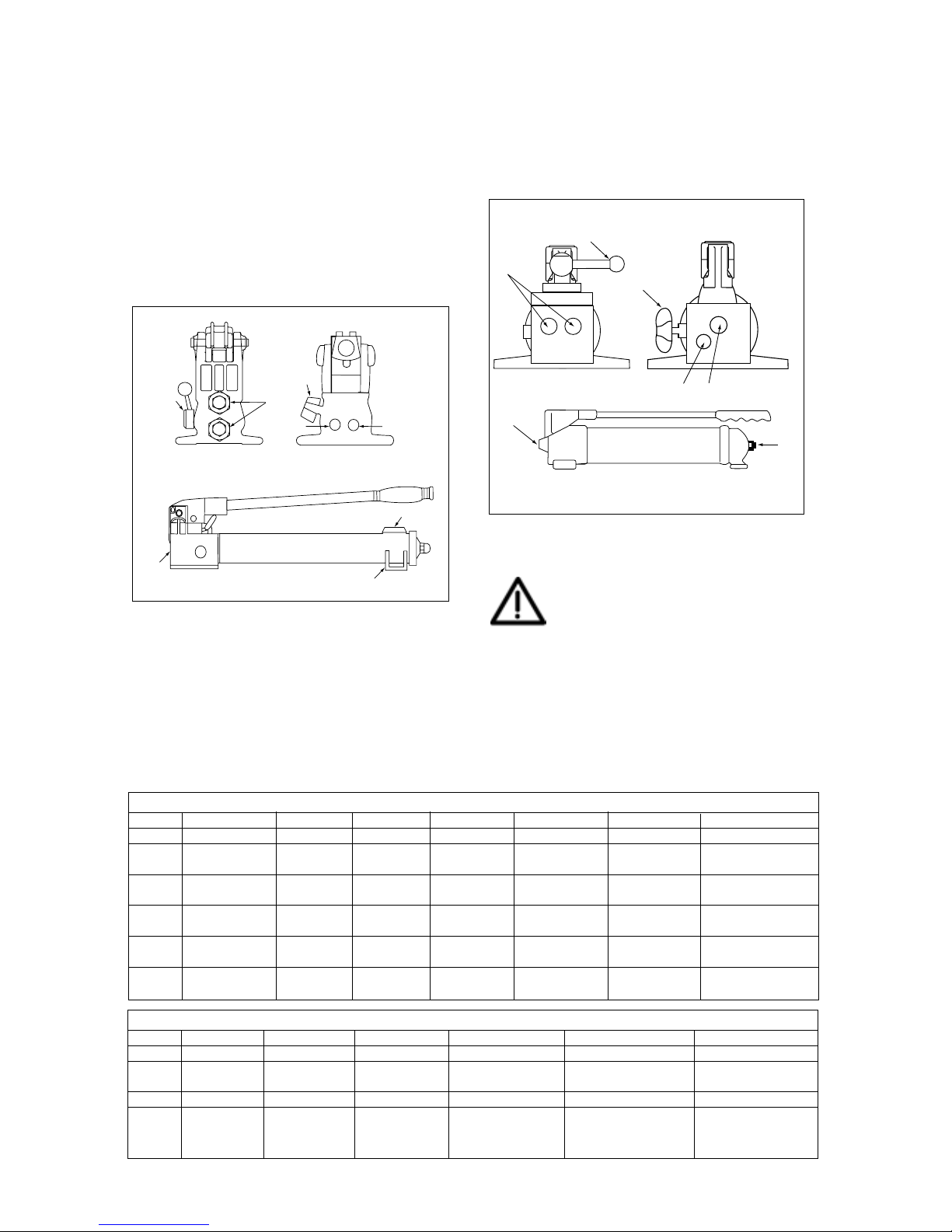
Figure 1 and the corresponding table show the main
components of hand pump models P-141, P-142, P202, P-391, P-392, P-802, and P-842. The dualpurpose vent/fill cap acts as a pressure relief valve in
case of accidental reservoir pressurization. To
provide an access port at the rear of the reservoir for
remote valves, use a return-to-tank kit. See the Table
1 for kit model numbers.
Figure 1
3.2 Models P-18/P-39, 1003/P-80, 1006/
P-84/P-801, P-77
Figure 2 and the corresponding table below show the
main components of these hand pump models.
Model P-84 is equipped with a 4-way, 3-position
valve for use with double-acting cylinders. To convert
models P-18 or P-39 to foot operation, order Kit PC-10.
Figure 2
WARNING: These pumps are operated
with a non-vented reservoir. If the
reservoir is subjected to high pressure,
the casing may rupture, causing
personal injury and/or equipment damage.
NEVER attempt to return more oil to the reservoir
than it is capable of holding.
B
A
A
DB
C
B
P842
D
C
B
B
A
A
BE
3
Tab le 1
Fig. 1 P-141, 1001 P-142, 1002 P-202 P-391, 1004 P-392, 1005 P-802 P-842
A Release Valve Release Valve Release Valve Release Valve Release Valve Release Valve 4-Way Valve
B 1 /4 NPTF 1 /4 NPTF 1 /4 NPTF 3/8 NPTF 3/8 NPTF 3/8 NPTF 3/8 NPTF
Outlet Port Outlet Port Outlet Port Outlet Port Outlet Port Outlet Port Outlet Port
C Vent/Fill Vent/Fill Vent/Fill Vent/Fill Vent/Fill Vent/Fill Vent/Fill
Cap Cap Cap Cap Cap Cap Cap
D Mounting Mounting — — — Mounting Mounting
Slots Slots Slots
E — — — — — Return-to-Tank —
Por t
Return-to PC-20 PC-20 PC-25 PC-25 PC-25 — —
-Tank Kit
Tab le 2
Fig. 2 P-18 P-39, 1003 P-77 P-80, 1006 P-84 P-801
A Release Valve Release Valve Release Valve Release Valve Release Valve Release Valve
B 3/8 NPTF 3/8 NPTF 3/8 NPTF 3/8 NPTF 3/8 NPTF 3/8 NPTF
Outlet Port Outlet Port Outlet Port Outlet Port Outlet Port Outlet Port
C Fill Plug Fill Plug Fill Plug Fill Plug Fill Plug Fill Plug
D — — — 1/4 NPTF
—
1/4 NPTF
Return-to-Tank Port Return-to-Tank Port
Page 4

3.3 Models P-462 and P-464
Figure 3 and the table below show the main features
of hand pump models P-462, for use with singleacting cylinders, and P-464, for use with doubleacting cylinders.
Figure 3, Models P-462, P-464
3.4 Models P-25, P-50, and P-51
Figure 4 shows hand pump models P-25 and P-50,
both of which are equipped with a handle that
operates in both directions. Figure 5 shows the P-51
hand pump. The main components of these pumps
are listed in the table below.
Figure 4, Models P-25 and P-50
Figure 5, Model P-51
4.0 INSTALLATION
4.1 Connecting the Pump
1. Thread hose into pump outlet. Use 1 1/2 wraps of
Teflon tape (or suitable thread sealant) on hose
fitting, leaving the first complete thread free of tape
to ensure that tape does not shed into hydraulic
system, causing damage. Trim loose ends.
2. Install a pressure gauge in-line from the pump for
added safety and better control.
3. Connect the hose(s) to your cylinder or tool.
NOTE: For single-acting cylinders, connect one
hose from the pump to the cylinder. For doubleacting cylinders, connect two hoses. Connect
one hose from the pressure port of the pump to
the pressure port of the cylinder. Connect another
hose from the retract port of the pump to the
retract port of the cylinder.
4.2 Pump Venting
See table below to determine if your pump should be
operated with a vented or non-vented reservoir.
Vented pumps provide slightly better performance.
For pumps with nylon reservoir, turn vent/fill cap 1/4
turn counter-clockwise to vent. For other pumps, see
decal on pump. Close vent prior to transporting
pump to prevent oil leakage. P-80, P-801, and P-84
are vented by turning the valve counterclockwise. To
close the vent, turn the valve clockwise.
4.3 Pump Position
See table below to determine the correct operating
position for your pump, horizontal or vertical. The P-80,
P-801, and P-84 cannot be vented when operated vertically.
OPERATING POSITION
EHF-65 . . . . . . . . . either
P-18 . . . . . . . . . . . either
P-25 . . . . horizontal only
P-39, 1003 . . . . . . either
P-50 . . . . horizontal only
P-51 . . . . horizontal only
P-80, 1006 . . . . . . either
P-84 . . . . . . . . . . . either
P-141, 1001 . . . . . either
P-142, 1002 . . . . . either
P-142AL . . . . . . . . either
P-202 . . . . . . . . . . either
P-391, 1004 . . . . . either
P-77 . . . . . . . . . . . either
P-392, 1005 . . . . . either
P-392AL . . . . . . . . either
P-462 . . . horizontal only
P-464 . . . horizontal only
P-801 . . . . . . . . . either
P-802 . . . . . . . . . . either
P-842 . . . . . . . . . . either
VENTING OPTIONS
EHF-65 ..........non-vented
P-18 ...............non-vented
P-25 ........................either
P-39, 1003 .....non-vented
P-50 ........................either
P-51 ......................vented
P-80, 1006 ..............either
P-84 ........................either
P-141, 1001 ............either
P-142, 1002 ............either
P-142AL.........non-vented
P-202 ......................either
P-391, 1004 ............either
P-77 ......................vented
P-392, 1005 ........... either
P-392AL ................vented
P-462 ....................vented
P-464 ....................vented
P-801 .............non-vented
P-802 ......................either
P-842 ......................either
Table 4 and 5
Fig. 4 & 5 P-25 P-50 P-51
A Release Valve Release Valve Release Valve
B 1/4 NPTF 1/4 NPTF 1/4 NPTF
Outlet Port Outlet Port Outlet Port
C Vent/Fill Cap Vent/Fill Cap Vent/Fill Cap
Tab le 3
Fig. 3 P-462 P-464
A 3-Way 2-Position Valve 4-Way 3-Position Valve
B 3/8 NPTF Outlet Port 3/8 NPTF Outlet Port
C Vent/Fill Plug Vent/Fill Plug
D Handle Clip Handle Clip
4
Page 5

NOTE: When operating the pump in the vertical
position, the hose end must be pointed down, or the
pump will pick up air and will not build pressure properly.
5.0 OPERATION
5.1 Before Using the Pump
1. Check all system fittings and connections to be
sure they are tight and leak free.
2. Check oil level in reservoir before operating
pump. See "Adding Oil to the Pump" on page 7.
CAUTION: NEVER add extensions to
pump handle. Extensions cause
unstable pump operation.
WARNING: In certain situations the
pump handle can "kick back". Always
keep your body to the side of the pump,
away from the line of force of the handle.
NOTE: To reduce handle effort at high pressure, take
short strokes. Maximum leverage is obtained in the
last 5° of stroke.
5.2 Using Two-Speed Pumps
These pumps provide 2-stage flow. Under no-load,
the pump operates in the high flow first stage for
rapid advance. When the load is contacted, the pump
automatically shifts to the second stage for building
pressure. For P-462 or P-464 models, when pump
pressure reaches approximately 200 psi [14 bar], you
must momentarily stop pumping and raise the handle
to shift to the high pressure stage. For P-802 or
P-842 models, when pump pressure reaches
approximately 400 psi [28 bar], you must momentarily
stop pumping and raise the handle to shift to the high
pressure stage. After the pump shifts, pumping takes
less effort.
NOTE: For best performance, operate pump handle
at moderate speed during the high flow first stage.
Rapid handle speed in the first stage will prevent the
pump from delivering full volume of oil.
5.3 Single-Acting Applications with
Release Valve
1. Close release valve by turning clockwise, as
shown in Figure 6.
Figure 6
CAUTION: Close release valve finger
tight ONLY. Using tools on release valve
can damage it and cause the pump to
malfunction.
2. Operate pump handle to deliver hydraulic power
to system. Pressure will be maintained until
release valve is opened.
3. Open release valve (turn counter-clockwise) to
release pressure, allowing oil to flow back to the
reservoir.
5.4 Single-Acting Applications with 3-Way,
2 Position Manual Valve
1. Shift valve handle to position 1 as shown in Figure 7.
2. Operate pump handle to deliver hydraulic power
to the system. Pressure will be maintained until
the valve is shifted.
3. To allow oil to return to the reservoir, shift valve
handle to position 2.
Figure 7
5.5 Double-Acting Applications with 4-Way,
3 Position Manual Valve
Pumps with 4-way control valves are designed to
operate double-acting cylinders. See Figure 8 for
valve positions.
Figure 8a
5
Page 6

Figure 8b
1. Position lever on 4-way valve to select function as
follows:
(A) Flow to Port "A"; port "B" returns flow to the
reservoir
(N) Neutral; ports "A" and "B" are blocked
(B) Flow to port "B"; port "A" returns flow to the
reservoir
Figure 8c
2. Operate pump to perform work.
3. Change valve positions as needed.
WARNING: Operate double-acting
cylinder only when both hoses are
connected to the pump. If one coupler
is left unconnected, high pressure will
build behind the coupler which could cause
personal injury and/or equipment damage.
5.6 Relief Valve Adjustment
All pumps contain a factory set relief valve to prevent
over-pressurization of the system. Lower pressure
settings can be obtained. Contact your Authorized
Enerpac Service Center.
6.0 AIR REMOVAL
Removing air from the hydraulic system will help the
cylinder to advance and retract smoothly (see figure 9).
6.1 Pump With Single-Acting Cylinder (A)
1. Vent pump reservoir (for vented pumps only) and
close release valve.
2. Position pump at higher elevation than cylinder.
3. Position cylinder with the plunger end down (up if
using pull cylinder). See Figure 9 below.
4. Operate pump to fully extend the cylinder (retract
if using pull cylinder).
5. Open release valve to retract cylinder (extend if a
pull cylinder). This will force the trapped air to
move up to the pump reservoir.
6. Repeat the above steps as necessary.
7. Add oil if necessary. See page 7.
8. Return vent/fill cap to operating position.
6.2 Pump With Double-Acting Cylinder (B)
1. Vent pump reservoir (for vented pumps only).
2. Position pump at higher elevation than cylinder.
3. Put cylinder in horizontal position with ports up.
See Figure 9.
4. Fully advance and retract the cylinder 2 to 3 times.
5. Repeat the above steps as necessary.
6. Add oil if necessary. See page 7.
7. Return vent/fill cap to operating position.
7.0 MAINTENANCE
Use only Enerpac hydraulic oil with these pumps to
promote long pump life and to protect your warranty.
Viton and EPR seal kits are available for some hand
pumps. Contact your Enerpac representative for more
information on these products and their applications.
6
Figure 9
air
air
Page 7

7.1 Adding Oil to the Pump
Check oil level regularly.
WARNING: Always add oil with
cylinders fully retracted (extended if
pull cylinders) or the system will contain
more oil than the reservoir can hold.
1. Remove vent/fill cap from reservoir.
2. Fill reservoir only to level mark shown on pump.
3. Remove air from system if necessary. See page 6.
Recheck oil level after removing air.
4. Return vent/fill cap to proper position.
NOTE: Non-vented hand pumps require air in the
reservoir to function properly. If the reservoir is
completely filled, a vacuum will form preventing
oil from flowing out of the pump.
7.2 Keeping Oil Lines Clean
When coupler halves are disconnected, always screw
on dust caps. Use every precaution to guard unit
against entrance of dirt because foreign matter may
cause pump, cylinder, or valve failure.
7.3 Lubricating the Pump
To extend pump life and improve performance,
lubricate the beam pin (A), cross pin (B), and piston
head (C) regularly, using roller bearing grease. See
Figure 10.
Figure 10
7.4 Changing the Oil
1. Drain all oil and refill with clean Enerpac oil every
12 months. If pump is used in dirty environments,
change the oil more often.
2. Remove vent/fill cap or plug from reservoir.
3. Tilt pump to drain out old oil.
4. Fill reservoir only to level mark shown on pump.
5. Replace the vent/fill cap or plug.
6. Dispose of used oil properly.
8.0 TROUBLESHOOTING GUIDE
The following information is intended as an aid in
determining if a problem exists. For repair service,
contact the Authorized Enerpac Service Center in
your area.
7
TROUBLESHOOTING
Problem Possible Cause Solution
Cylinder does not
advance, advances
slowly, or advances in
spurts.
Cylinder advances, but
does not hold pressure.
Cylinder does not retract,
retracts part way, or
retracts more slowly than
normal.
1. Oil level in pump reservoir is
low.
2. Release valve open.
3. Loose hydraulic coupler.
4. Load is too heavy.
5. Air trapped in system.
6. Cylinder plunger binding.
1. Leaking connection.
2. Leaking seals.
3. Internal leakage in pump.
1. Release valve closed.
2. Pump reservoir is over-filled.
3. Loose hydraulic coupler.
4. Air trapped in system.
5. Hose I.D. too narrow.
6. Cylinder retraction spring
broken or other cylinder
damage.
1. Add oil according to the Maintenance instructions on
page 6.
2. Close the release valve.
3. Check that all couplers are fully tightened.
4. Do not attempt to lift more than rated tonnage.
5. Remove air according to the instructions on page 6.
6. Check for damage to cylinder. Have cylinder serviced by
a qualified hydraulic technician.
1. Check that all connections are tight and leak free.
2. Locate leak(s) and have equipment serviced by a
qualified hydraulic technician.
3. Have pump serviced by a qualified hydraulic technician.
1. Open release valve.
2. Drain oil level to full mark. See page 7 instructions for
adding oil.
3. Check that all couplers are fully tightened.
4. Remove air according to the instructions on page 6.
5. Use larger diameter hydraulic hose.
6. Have cylinder serviced by a qualified hydraulic
technician.
 Loading...