

Page 1
Instruction Sheet
POWERFUL SOLUTIONS. GLOBAL FORCE.
L2923 Rev. B 09/09
Index:
English. . . . . . . . . . . . . . . . . . . . . . . . . . . . . . . . . . . . . . 1-7
Français. . . . . . . . . . . . . . . . . . . . . . . . . . . . . . . . . . . . . N/A
Deutsch . . . . . . . . . . . . . . . . . . . . . . . . . . . . . . . . . . . . . N/A
Italiano. . . . . . . . . . . . . . . . . . . . . . . . . . . . . . . . . . . . . . N/A
Español . . . . . . . . . . . . . . . . . . . . . . . . . . . . . . . . . . . . . N/A
Nederlands . . . . . . . . . . . . . . . . . . . . . . . . . . . . . . . . . . N/A
Portuguese . . . . . . . . . . . . . . . . . . . . . . . . . . . . . . . . . . N/A
Finnish . . . . . . . . . . . . . . . . . . . . . . . . . . . . . . . . . . . . . . N/A
Norwegian . . . . . . . . . . . . . . . . . . . . . . . . . . . . . . . . . . . N/A
Swedish. . . . . . . . . . . . . . . . . . . . . . . . . . . . . . . . . . . . . N/A
中文 . . . . . . . . . . . . . . . . . . . . . . . . . . . . . . . . . . . . . . . . N/A
日本語 . . . . . . . . . . . . . . . . . . . . . . . . . . . . . . . . . . . . . . N/A
Repair Parts Sheets for this product are available from the
Enerpac web site at www.enerpac.com, or from your nearest
Authorized Enerpac Service Center or Enerpac Sales offi ce.
1.0 IMPORTANT RECEIVING INSTRUCTIONS
Visually inspect all components for shipping damage. Shipping
damage is not covered by warranty. If shipping damage is found,
notify carrier at once. The carrier is responsible for all repair and
replacement costs resulting from damage in shipment.
SAFETY FIRST
2.0 GENERAL HYDRAULIC SAFETY PRECAUTIONS
Read all instructions, warnings and cautions
carefully. Follow all safety precautions to avoid
personal injury or property damage during system
operation. Enerpac cannot be responsible for damage or injury
resulting from unsafe product use, lack of maintenance or
incorrect product and/or system operation. Contact Enerpac
when in doubt as to the safety precautions and operations. If
you have never been trained on high-pressure hydraulic safety,
consult your distribution or service center for a free Enerpac
Hydraulic safety course.
Failure to comply with the following cautions and warnings
could cause equipment damage and personal injury.
A CAUTION is used to indicate correct operating or
maintenance procedures and practices to prevent damage to,
or destruction of equipment or other property.
A WARNING indicates a potential danger that requires correct
procedures or practices to avoid personal injury.
A DANGER is only used when your action or lack of action
may cause serious injury or even death.
WARNING: Wear proper personal protective gear
when operating hydraulic equipment.
WARNING: Do not exceed equipment ratings.
Overloading causes equipment failure and possible
personal injury. The nut splitter is designed for a
maximum pressure of 700 bar [10,000 psi]. Do not connect the
nut splitter to a pump with a higher pressure rating.
Never set the relief valve to a higher pressure than the
maximum rated pressure of the pump. Higher settings
may result in equipment damage and/or personal
injury.
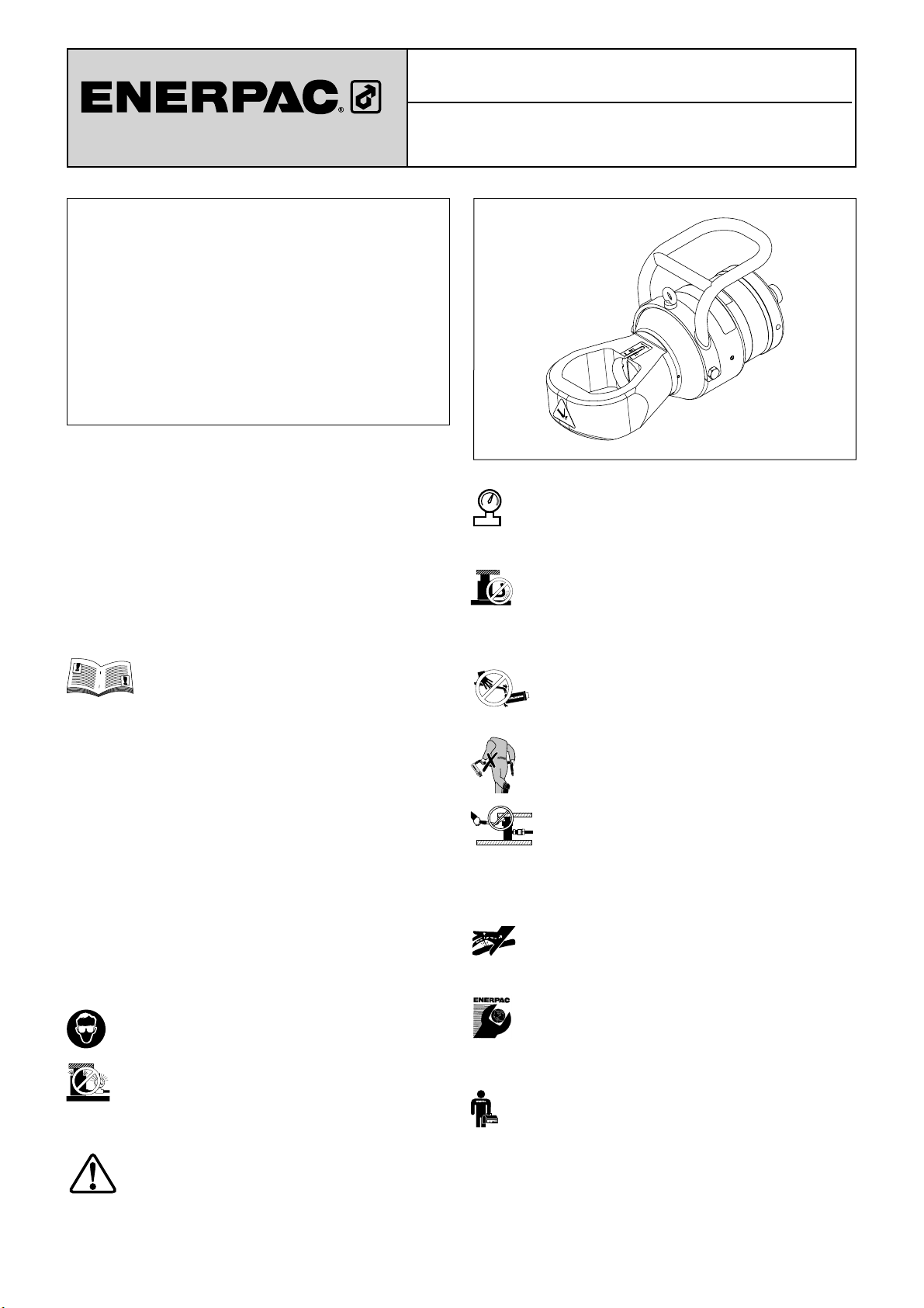
NS Series Hydraulic Nut Splitter
WARNING: The system operating pressure must not
exceed the pressure rating of the lowest rated
component in the system. Install pressure gauges in
the system to monitor operating pressure. It is your window to
what is happening in the system.
CAUTION: Avoid damaging hydraulic hose. Avoid
sharp bends and kinks when routing hydraulic hoses.
Using a bent or kinked hose will cause severe back-pressure.
Sharp bends and kinks will internally damage the hose leading
to premature hose failure.
Do not drop heavy objects on hose. A sharp
impact may cause internal damage to hose wire
strands. Applying pressure to a damaged hose
may cause it to rupture.
IMPORTANT: Do not lift hydraulic equipment by the
hoses or swivel couplers. Use the carrying handle or
other means of safe transport.
CAUTION: Keep hydraulic equipment away from
fl ames and heat. Excessive heat will soften
packings and seals, resulting in fl uid leaks. Heat
also weakens hose materials and packings. For optimum
performance do not expose equipment to temperatures of
65°C [150°F] or higher. Protect hoses and cylinders from weld
spatter.
DANGER: Do not handle pressurized hoses.
Escaping oil under pressure can penetrate the skin,
causing serious injury. If oil is injected under the skin,
see a doctor immediately.
IMPORTANT: Hydraulic equipment must only be
serviced by a qualifi ed hydraulic technician. For repair
service, contact the Authorized ENERPAC Service
Center in your area. To protect your warranty, use only ENERPAC
oil.
WARNING: Immediately replace worn or damaged
parts with genuine ENERPAC parts. Standard grade
parts will break causing personal injury and property
damage. ENERPAC parts are designed to fi t properly and
withstand high loads.
1
Page 2
2.1 Hydraulic Nut Splitter Safety Precautions
WARNING: Failure to observe the following precautions
may result in serious personal injury or death!
• Personal protective equipment must be worn at all times. Use
of safety footwear, thick gloves, overalls and safety glasses
is mandatory. These items are in addition to any other safety
equipment required at your site.
• Keep personnel clear while pressurizing the system. Allow
only relevant personnel to be within the work zone.
• Never exceed the maximum working pressure of the nut
splitter or any associated ancillary equipment. The maximum
working pressure of the nut splitter is 10,000 psi [700 bar].
• Do not place fi ngers or any part of the body between the nut
splitter and the nut. Keep hands clear of the nut splitter head
at all times and especially in the vicinity of the blade.
• Do not place fi ngers or hands underneath the body of the
nut splitter to support the weight, as hands or limbs could be
trapped when the pressure is applied.
• Lift the nut splitter using only the provided lifting eyebolt.
Always use appropriate lifting equipment. See Section 3.1 for
weights.
• The nut splitter handle is provided for positioning and
maneuvering purposes only. Do not use the handle to carry the
nut splitter.
• Do not strike the nut splitter (or any of its components) with a
hammer or other objects in an attempt to shock or impact the
nut.
• Do not attempt to move or reposition the nut splitter while it
is in operation.
• Do not apply heat to the nut while the nut splitter is positioned
on the nut.
• When in operation, do not stand along the axis of the nut
splitter. Always stand to the side.
• Do not cut the nut into small pieces. Use a maximum of two
cuts. The second cut must always be at 180º (opposite) to the
fi rst.
• Hydraulic couplers are susceptible to knocks and damage.
Therefore, be careful when handling the equipment. A damaged
coupler or fi tting may burst or eject fl uid under pressure.
• Always allow the nut splitter cylinder to fully retract before
disconnecting hydraulic hose(s). High-pressure fl uid may be
ejected from an unretracted cylinder if a coupler has been
damaged during handling.
• Fully release hydraulic pressure and disconnect hydraulic
hose(s) from nut splitter cylinder before applying lubricant to
blade or performing any other work inside the cutting zone.
• Be careful when handling severed nuts. Sharp edges can
cause lacerations.
• Always use the correct size cutting head for the nut to be
cut.
• Do not insert packing pieces or shims behind the nut or
blade in an attempt to split a nut that is not within the specifi ed
size range for the cutting head.
• Use the nut splitter to cut hexagonal nuts only. Do not attempt
to cut square, round, bi-hex or 12-point nuts.
• Do not use the nut splitter to cut chains or bolts.
• Do not use the nut splitter to rotate nuts.
• Do not use the nut splitter's hydraulic cylinder for jacking,
lifting, pushing or any other purpose than that for which it is
intended.
• Sparks can be emitted at the blade tip when the nut fractures.
To minimize the risk of sparks or hot metal fragments, a water
spray can be directed over the entire nut and blade area.
However if there is any doubt as to whether sparks can be
effectively arrested, then the nut splitter should not be used.
• Never attempt to disconnect or retighten any part of the
hydraulic system while under pressure. Be sure pressure
gauge indicates zero (0) psi/bar before attempting to connect,
disconnect or tighten hydraulic fi ttings.
• Treat hydraulic hoses with care. Do not kink, twist or sharply
bend any hydraulic hose. Never exceed the hose manufacturer's
specifi ed minimum bend radius. Never use a damaged, worn
or split hose.
• Read and understand the operating instructions, maintenance
instructions and safety precautions contained in this instruction
sheet.
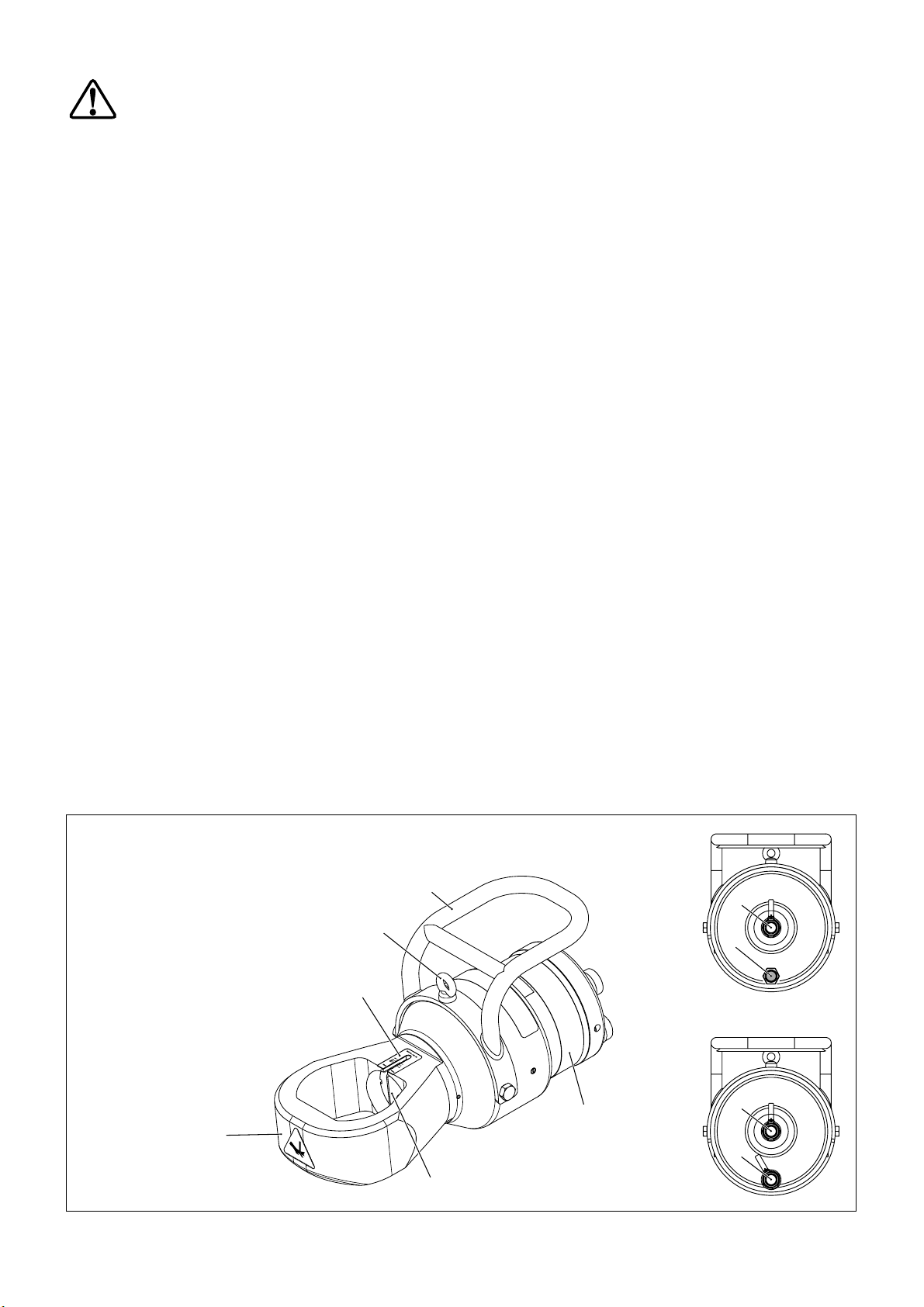
1. Cutting Head
2. Blade Cutting Depth Scale
3. Lifting Eyebolt
4. Handle
5. Hydraulic Coupler
6. Vent Plug
(single acting NS70 models only)
7. Pipe Plug
(single acting NS110 models only)
8. Hydraulic Coupler
(double acting models only)
9. Hydraulic Cylinder
10. Cutting Blade
1
4
3
2
9
10
Figure 1, Features and Components, NS Series Nut Splitter
2
Single
Acting
Models
Double
Acting
Models
5
6,
7
(rear view)
5
8
Page 3
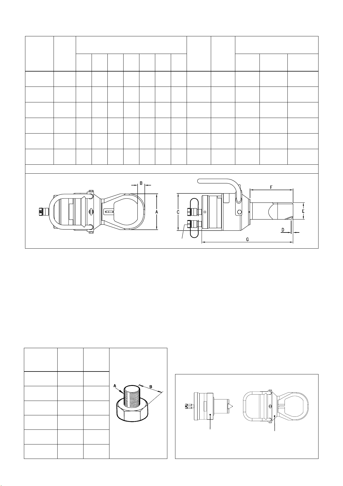
3.0 SPECIFICATIONS
3.1 Product Data
Nut Splitter
Model
Number
NS-7080
NS-7080D
Capacity
tons [kN]
103.2
[918]
Dimensions
inch [mm]
ABCDEFG
5.2
1.1
7.1
0.3
3.2
7.3
[132]
[28]
[180]
[8.0]
[81]
[186]
16.2
[412]
Weight
lb [kg]
81.4
[37.0]
Minimum
Pump Oil
Capacity
3
in
[cm3]
23.0
[377.0]
Additional Model Numbers
Cylinder
Sub-
Assembly
NSC-70
NSC-70D
Cutting
Head Sub-
Assembly
NSH-7080 NSB-70
Replacement
Blade
NS-7085
NS-7085D
NS-7095
NS-7095D
NS-70105
NS-70105D
NS-110115
NS-110115D
NS-110130
NS-110130D
Note: A model number ending with “D” indicates double acting.
103.2
[918]
103.2
[918]
103.2
[918]
192.5
[1712]
192.5
[1712]
5.7
[145]
6.3
[160]
6.9
[174]
7.4
[189]
8.6
[219]
1.2
[30]
1.3
[32]
1.4
[35]
1.4
[36]
1.6
[41]
7.1
[180]
7.1
[180]
7.1
[180]
9.2
[234]
9.2
[234]
0.3
[8.0]
0.3
[8.0]
0.4
[9.0]
0.1
[3.7]
0.1
[2.5]
3.2
[81]
3.2
[81]
3.2
[81]
4.4
[111]
4.4
[111]
7.7
16.6
[196]
[422]
7.9
[201]17[432]
17.5
8.2
[209]
[443]
9.2
18.6
[234]
[472]
9.5
19.4
[242]
[493]
Double Acting Only
82.7
[37.5]
84.9
[38.5]
87.1
[39.5]
151.6
[68.8]
158.3
[71.5]
23.0
[377.0]
23.0
[377.0]
23.0
[377.0]
50.0
[819.5]
50.0
[819.5]
NSC-70
NSC-70D
NSC-70
NSC-70D
NSC-70
NSC-70D
NSC-110
NSC-110D
NSC-110
NSC-110D
NSH-7085 NSB-70
NSH-7095 NSB-70
NSH-70105 NSB-70
NSH-110115 NSB-110
NSH-110130 NSB-110
Notes:
• The NS Series is available in both single and double acting
models. Single acting models use spring force to retract the
blade. Double acting models use hydraulic force to retract the
blade.
• A model number ending with “D” indicates that the nut
splitter (or cylinder sub-assembly) is double acting. Refer to
Section 3.1 for model numbers and additional information.
• Both single and double acting models use the same NSH
series cutting heads shown in Section 3.1.
3.2 Nut and Bolt Ranges
Cutting Head
Subassembly
Model Number
NSH-7080 1.75-2.00
NSH-7085 1.75-2.25
NSH-7095 1.75-2.50
NSH-70105 1.75-2.75
NSH-110115 2.75-3.00
NSH-110130 2.75-3.50
AB
Bolt Range
inch [mm]
[M45-M52]
[M45-M56]
[M45-M64]
[M45-M72]
[M76-M80]
[M76-M90]
Hexagon
Nut Range
inch [mm]
2.75-3.13
[70-80]
2.75-3.50
[70-85]
2.75-3.88
[70-95]
2.75-4.25
[70-105]
4.25-4.63
[110-115]
4.25-5.38
[110-130]
4.0 DESCRIPTION
The NS Series nut splitter is a hydraulically operated industrial
power tool, designed to quickly remove seized or heavily
corroded nuts from threaded studs.
See Figure 1 for an overview of NS nut splitter major features
and components.
A complete nut splitter consists of two separate subassemblies:
1) a single or double acting hydraulic cylinder and 2) a
matching cutting head designed for use with a specifi ed nut
size range. The replaceable cutting blade is installed in a blade
holder mounted on the shaft of the cylinder subassembly.
See Figure 2.
One cutting head is provided with each nut splitter. If desired,
additional cutting heads for different nut size ranges can be
purchased separately from Enerpac.
Refer to sections 3.1 and 3.2 for nut splitter specifi cations and
additional information.
Cylinder
Subassembly
Cutting Head
Subassembly
3
Figure 2, Nut Splitter Subassemblies
Page 4

5.0 ASSEMBLY
5.1 Assembling Cutting Head and Cylinder
The cutting head is shipped disassembled from the cylinder.
Assemble as described in the following steps:
1. Be sure that cylinder is fully retracted and disconnected
from the hydraulic pump.
2. Loosen the plastic set screw (Figure 3, item A) located on
the cutting head barrel.
3. Insert the cylinder into the head, aligning the axial slots
in the blade holder (Figure 3, item B) with the spring pins
(Figure 3, item C) in the cutting head bore. Once aligned,
rotate the cylinder in the direction shown in order to engage
the screw threads.
4. Continue rotating the cylinder until NO threads are visible on
the outside of the cylinder body (threads fully engaged).
WARNING:
Never use the nut splitter if any of the
cylinder threads are visible.
5. Install the cutting blade. Refer to Section 7.0 for installation
instructions.
Enerpac PU Series
Electric Pump
Enerpac P Series
Hand Pump
Enerpac PA Series
Air-Hydraulic Pump
0-10,000 psi
[0-700 bar]
Pressure Gauge
Note:
Hose arrangement for
single acting nut splitter
models is shown.
Double acting nut splitter
models require TWO
hoses, one for extend
and one for retract.
B
C
B
C
A - Set Screw
B - Grooves
A
Figure 3, Assembling the Cylinder and Cutting Head
5.2 Hydraulic Pump
A 10,000 psi [700 bar] hydraulic pump is required to operate
the nut splitter.
If a single acting nut splitter is used, the pump must be
equipped with a pressure release valve. If a double acting nut
splitter is used, the pump must be equipped with a suitable
4-way 3-position directional control valve.
Always check the pump hydraulic relief valve setting before
connecting the nut splitter. Maximum pressure must not exceed
10,000 psi [700 bar].
If an air-powered hydraulic pump is used, an air regulator must
be installed in the air supply line, limiting the air pressure to the
recommended range for the pump being used.
If the pump is not equipped with a hydraulic pressure gauge,
install a 0-10,000 psi [0-700 bar] gauge between the pump
outlet and the hydraulic hose.
5.3 Hose Connections
Be sure to use only high pressure hoses and fi ttings designed
for 10,000 psi [700 bar] operation. See Figure 4 for typical
pump and hose arrangements.
Single acting nut splitters are equipped with one Enerpac
CR-400 3/8" female coupler. Double acting nut splitters are
equipped with two Enerpac CR-400 3/8" female couplers.
C - Spring Pins (inside bore)
Enerpac XA Series
Hydraulic Pump
Figure 4, Hydraulic Connections (typical pumps shown)
Connect the hydraulic hose(s) between the pump and the nut
splitter cylinder. Check that couplers on both ends of hose(s)
are fully screwed together. Firmly tighten couplers by hand to
prevent restricted oil fl ow.
IMPORTANT: Be sure that all couplers are fully connected.
Loose or partially connected couplers will block the fl ow of oil
between the pump and the nut splitter.
To remove any air trapped in the system, advance and retract
the cylinder several times.
6.0 OPERATION
6.1 Adjusting Blade Cutting Depth
(If bolt diameter is shown on the scale)
The blade cutting depth scale allows the user to set the nut
splitter's maximum stroke, and the corresponding depth of
the cutting blade. This feature helps prevent bolt damage from
occurring due to excessive blade penetration.
Adjust the cutting depth as described in the following steps:
1. Ensure that the nut splitter cylinder is fully retracted.
2. Check that the bolt diameter is within the range of the
cutting head to be used (bolt diameter range is indicated
on the scale). See Section 3.2 for additional information.
Note: The cutting depth scale is calibrated only for the following
thread, bolt and nut types:
Imperial threads - Unifi ed (UN) bolt threads with heavy series
nuts.
Metric threads - Metric (M) bolt threads with standard series
nuts.
If any other thread, bolt or nut type is present, skip the following
steps in this section and refer to Section 6.2 for additional
instructions.
4
Page 5

Note: Scale markings will vary
depending on cutting head size.
Figure 5, Blade Cutting Depth Scale
3. If tight, loosen the plastic set screw located on the cutting
head barrel. See Figure 3, item A.
4. Rotate the cutting head until the red marker line on the
blade holder is aligned with the required bolt size marker
line on the scale. See Figure 5.
5. Retighten the plastic set screw.
6.2 Adjusting Blade Cutting Depth
(If bolt diameter is NOT shown on the scale)
1. Measure the distance from the fl at of the nut to the furthest
side of the bolt. See Figure 6.
2. Advance and hold the nut splitter cylinder at full stroke.
3. If tight, loosen the plastic set screw located in the barrel
portion of the cutting head. See Figure 3, item A.
4. Rotate the cutting head until the distance from the head
fl at to the tip of the blade is the same as the nut to
bolt distance previously measured in Step 1 PLUS an
additional 1 to 2 mm (1/16"). See Figure 7.
IMPORTANT: Ensure that the cylinder threads are not exposed.
If the threads are visible, a larger cutting head and possibly a
larger cylinder is required. Refer to Section 3.1 for additional
information.
5. Retighten the plastic set screw.
6. Retract the nut splitter cylinder.
“X” mm
“X” + 1-2 mm
5. To help prolong blade life, lubricate the blade cutting edge
and fl anks with a molybdenum disulphide based lubricant
or other high quality lubricant.
CAUTION:
prevent contact with skin.
Wear gloves when applying lubricants to
ABC
Figure 8, Positioning the Cutting Head
6. Position the cutting head over the nut, ensuring that the
fl at surface of the blade rests against one of the nut fl ats.
Centrally position the nut within the head so that the blade
will cut in the center of the nut fl at. See Figure 8, view “A”.
7. Ensure that the underside of the cutting head is seated
against the fl ange, as the blade must cut as close to the
bottom of the nut as possible. However, if a washer is
present under the nut, position the nut splitter so that the
cutting blade will not contact the washer. See Figure 9.
IMPORTANT: Improper positioning of the nut splitter may
cause damage to the cutting blade, blade holder and piston.
8. Vented pumps only: open the vent/fi ll plug or loosen the
vent screw to provide venting.
9. Air or electric powered pumps only: Set the pump to
deliver a nominal pressure of 1000 psi [69 bar].
Blade
Washer
Figure 9, Blade Position
Figure 6 Figure 7
6.3 Nut Splitting Procedure
1. Verify that the nut splitter cutting head is the correct size
(bolt range) for the nut to be cut. See Section 3.2.
2. Ensure that the nut splitter blade is in good condition and
that the cutting edge is not worn, chipped or damaged.
Rotate or replace blade as required.
3. Adjust the blade cutting depth to prevent damage to the
bolt threads. Refer to sections 6.1 and 6.2 for adjustment
instructions.
4. Connect hydraulic hose(s) as described in Section 5.3.
Check that hydraulic pump reservoir is fi lled to the correct
level.
WAR
NING:
To prevent personal
injury, do not place hands or
fi ngers in the cutting area.
WAR
NING:
reposition nut splitter during
operation.
10. Operate the pump to slowly advance the nut splitter blade
until it makes contact with the nut. Check that the blade is
resting squarely on the nut fl at.
5
Do not move or
Page 6

Notes:
• Air or electric powered pumps only: Once the blade has
stopped cutting at 1000 psi [69 bar], the pressure should be
gradually increased using the pressure regulator on the pump.
Allow adequate time for the blade to cut before increasing
pressure.
• If pressure is increased too quickly, blade damage may result.
Excessive pressure may also cause the nut splitter's internal
relief valve to open, resulting in oil leakage from the oil bleed
hole located on the underside of the blade holder.
• On larger nuts, it may be helpful to periodically retract and relubricate the blade. This will reduce friction and increase blade
effi ciency.
11. Continue to apply hydraulic pressure until the nut is
completely severed. As the nut splits, a loud “crack” will be
heard, indicating that the nut has been severed.
12. If necessary, a second cut
may be applied, at 180° to
the fi rst, completely severing
the nut in half. See Figure
10.
IMPORTANT: Do not cut the
nut into small pieces. Use a
maximum of two cuts and always
at 180º (opposite) to the fi rst.
Otherwise, nut metal fragments
Fig. 10, Making Two Cuts
may be released.
13. After the cut is completed:
• Single acting models: Release the pressure to retract
the nut splitter blade.
• Double acting models: Move the control valve to the
retract position to retract the nut splitter blade.
14. Stop the pump. Check that pressure gauge indicates zero
(0) psi/bar.
15. Remove nut splitter from the nut.
16. Remove the severed nut from the stud.
6.4 If Nut Does Not Split at Full Hydraulic Pressure
If the nut splitter is at full pressure, 10,000 psi [700 bar], and
the nut does not split:
WARNING
: Fully release hydraulic pressure and
disconnect hydraulic hose(s) from nut splitter cylinder
before applying lubricant to blade or performing any
other work inside the cutting zone.
1. Ensure that the blade cutting depth setting is correct. Also,
check that the cylinder is not at full stroke.
2. If the blade cutting depth setting is correct and cylinder
is not at full stroke: Release hydraulic pressure and rotate
the cylinder clockwise one full turn. This will allow the blade
to advance 1 to 2 mm further. Then, re-apply hydraulic
pressure and try again to split the nut.
3. If step 2 did not work: Release hydraulic pressure. Re-
lubricate the blade and the groove in the nut where the
blade has penetrated. Then, re-apply pressure, ensuring
that the blade is positioned back in the same nut groove.
4. If step 3 did not work: Re-lubricate the blade and the
nut groove again. Lift and position the nut splitter above
the fl ange surface so that the blade will penetrate the nut
approximately ²⁄³ the height of the nut, and in the same
groove. Then, re-apply pressure.
5. If step 4 did not work: Install a larger cutting head (if
available) or use a larger nut splitter model. Be certain
that the nut size is within the larger equipment's operating
range.
6.5 After Using the Nut Splitter
1. Ensure that the nut splitter cylinder is fully retracted. If it
is fully or partially advanced, reconnect the cylinder to
the pump and allow time for full retraction to occur. After
ensuring that there is no pressure present in the system,
disconnect the hydraulic hose(s) from the cylinder.
2. Using a clean cloth, wipe away any debris from the nut
splitter components. Pay particular attention to the cutting
head and blade area. Remove all traces of lubricant from
the blade.
3. Reinstall dust caps and/or plugs on all hydraulic couplers.
4. If the nut splitter is to be stored in damp conditions or will
not be used for a long period of time, coat exterior surfaces
with a water-repellent spray or similar removable protective
coating.
5. Store the nut splitter subassemblies in their storage cases.
7.0 CUTTING BLADE REPLACEMENT
The blade features three separate cutting edges. If one edge
becomes damaged or severely chipped, the blade can be
removed, rotated 120 degrees, and reinstalled to provide a
new cutting edge.
IMPORTANT: After all three edges are worn, the blade should
be replaced. Do not attempt to sharpen worn or damaged
blades.
Replace the blade as described in the following steps. See
Figure 11.
1. Be sure that nut splitter cylinder is fully retracted and that
pressure gauge indicates zero (0) psi/bar. Disconnect
hydraulic hose(s) from cylinder coupler(s).
2. Slide the blade from the holder and out through the
underside of the head. If the blade is tight, a light tap on the
top surface of the blade should free it from the ball detent
mechanism.
C
AUTION: Be careful when handling blades. Fractured
edges can be sharp. Wear appropriate hand protection
when removing and installing blades.
3. Determine if the old blade has any reusable edges. If a new
blade is to be installed, refer to Section 3.1 for replacement
blade part numbers. Be sure to use the proper blade for the
cutting head used on your nut splitter model.
Ball Detent
Blade
(removed)
Blade
(installed)
Figure 11, Cutting Blade Replacement
6
Page 7

4. From the underside of the head, slide the new or rotated
blade into the dovetail shaped groove in the blade holder,
until the ball detent snaps into position. The blade is fully
installed when the bottom of the blade is fl ush with the fl at
W
ARNING: Fully release hydraulic pressure and
disconnect hydraulic hose(s) from nut splitter cylinder
before performing any adjustments, repairs or
maintenance.
bottom of the blade holder.
8.0 TROUBLESHOOTING
The Troubleshooting Chart is intended as a guide to help you
diagnose and correct various possible problems.
Only qualifi ed hydraulic technicians should troubleshoot
and service the nut splitter. For repair service, contact the
CAUTION: Piston retract spring and other internal
parts may eject from cylinder suddenly during
disassembly. To avoid personal injury, use caution if
cylinder disassembly is necessary. Cylinder
disassembly and repairs should be performed only by
qualifi ed personnel.
Authorized Enerpac Service Center in your area.
Troubleshooting Chart
Problem Possible Cause Action
1. Nut splitter cylinder will not
hold pressure.
2. Nut splitter cylinder builds
pressure, but piston and blade
do not move or move only a
partial amount.
3. Nut splitter cylinder will not
build pressure.
Piston seal leaking. Replace seal.
Coupler leaking. Replace coupler.
Cylinder internal relief valve malfunction. Check relief valve and replace if required.
Hydraulic pump malfunction.
Pump reservoir not vented.
Check hydraulic pump for proper operation.
Repair or replace pump as required.
If using a vented pump, loosen vent/fi ll cap
or vent screw as required to provide venting.
Coupler not fully assembled. Check couplers.
Both hoses not connected.
(double acting models only)
Be sure that both hoses are connected.
Piston at full stroke. Allow piston to retract.
Blocked hose. Replace hose.
Pump release valve open. Close pump release valve.
Piston seal leaking. Replace seal.
Cylinder internal relief valve malfunction. Check relief valve and replace if required.
Insuffi cient oil in pump. Add oil to pump reservoir as required.
4. Nut splitter cylinder will not
retract or retracts very slowly.
5. Nut splitter builds full pressure,
but will not split nut.
6. Hose is diffi cult to assemble.
7. Frequent blade replacement.
8. Leakage from nut splitter oil
bleed hole on underside of
blade holder.
Coupler leaking. Replace coupler.
Loose coupler. Check coupler and tighten if loose.
Restricted or blocked hose. Replace hose.
Incorrect coupler being used. Install correct coupler.
Incorrect hose being used. Install correct hose.
Pump release valve closed. Open pump release valve.
Broken or weak piston return spring.
(single acting models only)
Replace return spring.
(See Section 6.4 of instructions.) (See Section 6.4 of instructions.)
Damaged coupler. Replace coupler.
Internal pressure within hose. Vent hose.
Lubricant not used. Use lubricant.
Pressure above 10,000 psi [700 bar].
7
Release system pressure to allow cylinder
internal relief valve to reset.
 Loading...