

Page 1
Instruction Manual for MODEL EDI62SInstruction Manual for MODEL EDI62S 1/12
ED-34828
2008.10
1 Before Using the Unit
Thank you for purchasing our quality designed and manufactured EDI62S
Series. Before unpacking the unit, check for damages during transportation. If you have noticed any damage, directly contact us or our distributor.
1.1 Type Identification
Each model number of the EDI62S series ha s its general spe cifications, and the following describes each note and the meaning. Before
using the unit, check that the mod el number and specifications of the
delivered unit match th ose of the pr oduct you ordere d. For optional
units, see the sepa rate instruction Manuals.
1.2 Accessories
2 Mounting Method
2.1 Panel Cut Size
Cut th e panel to moun t the ED I62S ser ies in a ccordance with th e
illustration b elow:
The recommended panel thickness is 0.8 to 5.0mm.
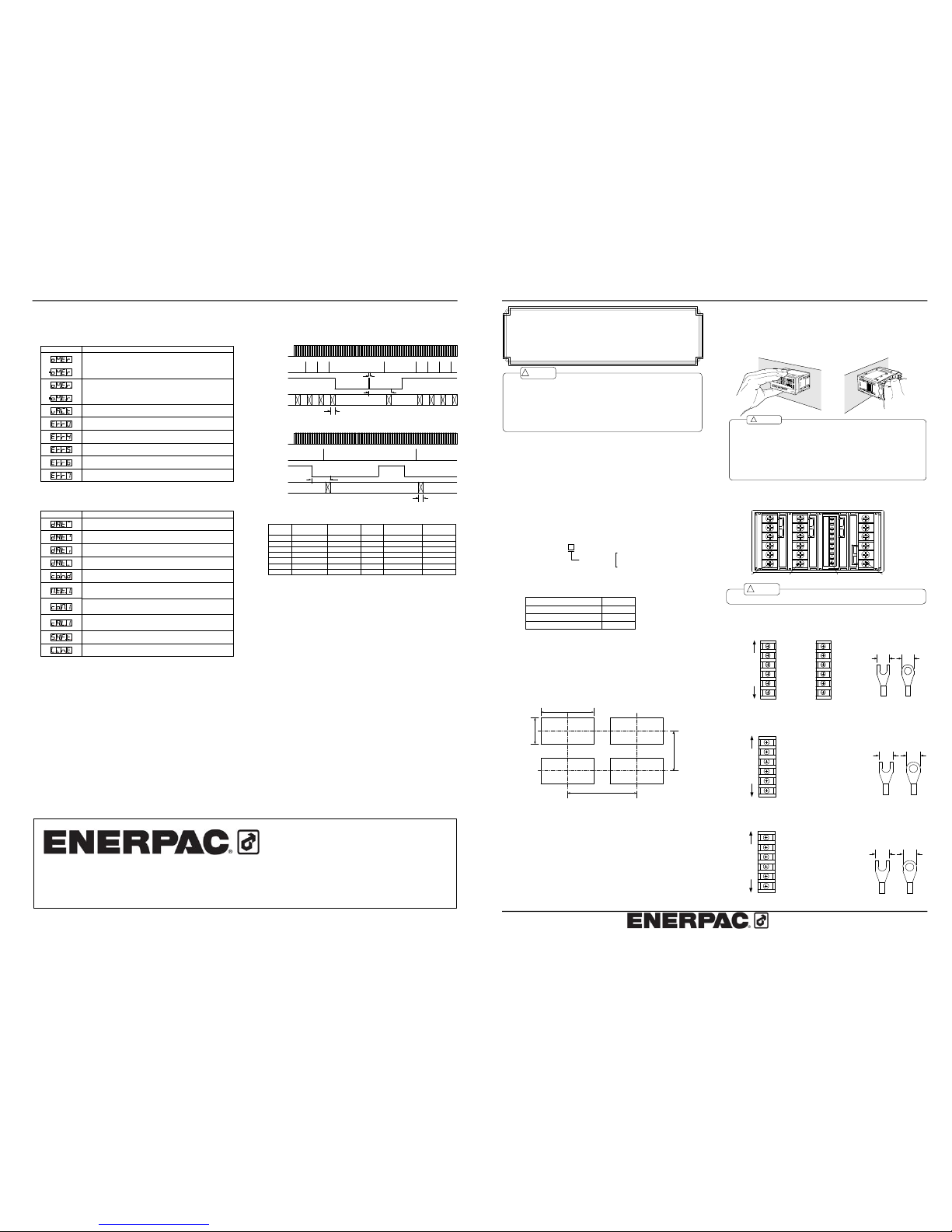
2.2 How to Mount the Unit on the Panel
Mount the EDI62S series to the panel in accordance with the illustra tion belo w:
3 Terminals and Connections
3.1 Power supply connections
3.2 Input Signal Connections
3.3 Comparator Output Connections
Each unit is not replaceable by the customer.
Caution
!
⑤AC POWER
⑥AC POWER
③NC
④NC
①NC
②NC
⑤NC
③NC
④NC
①DC POW(+)
②DC POW(-)
⑥NC
Top
Bottom
5.8 mm or
less
5.8 mm or
less
Suitable solderless terminals
AC power supply DC power supply
(1) Remove the mounting band and insert the case
from the front of the panel.
(2) Fix the case using the mounting band from the
rear of the panel.
(1)
Th e re c om m en d ed p a ne l th i ck ne s s is 0 .8 to 5 m m.
(2)
Do n o t in st al l th e u ni t in lo ca ti o ns w h er e it i s e xp os e d to di re ct s u nl ig ht ;
wh e re a m bi en t e mp e ra tu re or h um i di ty d o es n' t m ee t t he r eq u ir em e nt s b el ow ;
or w h er e a d ra st ic c h an g e in t em p er a tu re m a y au s e c on de n sa ti o n.
Am b ie nt t em p er a tu re : 0 t o 50 ℃
Am b ie nt h u mi di ty : 3 5 to 8 5 %
(3)
Do n o t in st al l th e u ni t w he re it i s ex po s ed t o d us t , pa rt ic le s , ch e mi ca ls ha rm f ul t o
el ec tr ic c o mp o ne n ts , co r ro si ve ga se s , et c.
(4)
Do n o t in st al l th e u ni t w he re it i s ex po s ed t o e xc e ss iv e v ib ra ti o n or s h oc k.
(5)
In st al l th e u ni t ho r iz on t al ly ; ot he r wi se , v en ti la t io n wi ll b e a dv e rs el y a ff ec te d a nd
ma y re s ul t in d e te ri o ra ti on .
(6)
Wh e n th is u n it i s in s ta ll ed i ns i de o th e r eq u ip me n t, p a y at te nt io n t o th e h ea t
ra di at io n a nd ke ep th e h ea t in si d e th e e qu ip m en t 5 0℃ o r b el ow .
Ca ution
!
Caution
!
(1) Applying a voltage or current exceeding its maximum permissible value may cause the unit to be
damaged.
(2)
(3)
(4)
(5)
For the purpose of functional improvement, the information written herein may be changed without
prior notice.
Always use the unit within the specified voltage range; otherwise, it may cause a fire, electric
shock or personal/equipment damage.
Information contained herein is considered accurate to the best of our knowledge. If you have any
question or comment on the information, please contact us or our distributor.
Read this manual carefully and thoroughly before starting to operate the unit, and keep the
manual available for future refer ence.
120 mm or more
70 mm or more
+0.6
-0
45
92
-0
+0.8
Instruction Manual for EDI62S Series
Digital Straingauge Meters
12/12
(ED-34824)
Unit in dication la bel
Access ory Quantit y
6-p ter minal cove r 3 piece s
1 each
Mounti ng band 2 piece s
Suitable solderles s termin als
5.8 mm or
less
5.8 mm or
less
Top
Bottom
①+SIG (D) sens or input ( +)
②-SIG ( B) sens or input (- )
③+EXC (A) sens or supply power ( +)
④-EXC (C) sens or supply power (- )
⑤AG (E ) anal og ground
⑥NC space termina l
Display Descrip tion
Indicate s that ea ch judgm ent value of compa rator dat a or the s ize of
hysteres is param eters doe s not me et the con ditions.
Indicate s that a signal ex ceeding th e measu rement ra nge has been
applied .
Indicate s that an input sig nal once exceeded the mea surement
range, b ut has re turned to the mea surable ra nge with the peak hold
function activate d.
Indicate s that th e unit is w aiting for an A/D c onverter input or t hat
power-O N delay time is v alid.
Indicate s that dig ital limite r HI and digital lim iter LO o f scaling data
have the same v alue.
Indicate s that an alog outp ut HI and analog o utput LO of scalin g data
have the same v alue.
Lineariz e data er ror
Indicate s that fu ll-scale in put value and off-s et input v alue of s caling
data ha ve the sa me value .
* Turning power O N with th e Enter k ey and M ode key held dow n causes all the
paramet ers to retu rn to the initial va lues (de faults).
Memory switch a rea, chec ksum err or of main memory
Calibrat ion data a rea, che cksum er ror of ma in memor y
Memory switch a rea, chec ksum err or of sub -memory
Calibra tion data area, che cksum e rror of su b-memory
Conditio n data a rea, chec ksum err or
Press th e Mode key for a prolonged time to l oad the i nitial valu es.
Scaling data area , checksu m error (f or each p attern)
Press the Mode k ey for a p rolonged time to lo ad the ini tial value s of each
pattern.
Compara tor data area, chec ksum erro r (for eac h pattern )
Press the Mode ke y for a pr olonged time to loa d the ini tial value s of each
pattern.
Calibrat ion data a rea, chec ksum erro r (for eac h pattern)
Press the Mode k ey for a p rolonged time to lo ad the ini tial value s of each
pattern.
Shift da ta area, checksum error
Press th e Mode key for a prolonged time to l oad the i nitial valu es.
Lineariz e data ar ea, chec ksum err or
Press th e Mode key for a prolonged time to l oad the i nitial valu es.
Display Descrip tion
*2 + time delay +(*1 ×2)+500μ s+*3
*2
*3
Time dela y +(*1×2) +500μs+* 3
*3
Internal
sampling
Specified
sampling
S/H term inal
Compara tor
output up date
Start/hold type A
*1
Internal
sampling
Specified
sampling
S/H term inal
Compara tor
output up date
Start/hold type B
*1
10 Error Message
10.1Error Indication during Measurement or Setup
10.2Memory Failure Error Indication
11 Timing Charts
12 Warranty and Service
12.1Warranty
The warrant y peri od of the product is one ye ar fro m the date of
delivery. If a failure occurs during this perio d that is clearly judged to
be cau sed by a defect asc ribable to Asahi Keiki , we will repair th e
failure or replace any defective parts without charge.
12.2After Sales Service
Under strict quality control measure s, this produc t was m anufactured, tested, inspected and shipped. Should a defect in manufacture
or workm anship be identified, please retu rn the pro duct to our distributor or directly to us. It would be highly appreciated i f you could
give a detail ed account of the faul t and enclose it with t he product.
*1 Specified sampling
AVG
setting
1
Sampling speed
1041.65 times/sec
2 520.825 times/sec
4
8
10 104.165 times/sec
205052.0825 times/sec
20.833 times/sec
AVG
setting
100
Sampling speed
10.4165 times/sec
200 5.20825 times/sec
400 2.604125 times/sec
800
1000 1.04165 times/sec
2000
5000
0.520825 times/sec
0.20833 times/sec
*2 External start signal
*3 Time delay for alarm outp ut
Relay output: 10 ms max.
The width of the external start signal must be from betwee n 500μs to a specified s ampling cycle. A time
delay can be set for the ex ternal start using the S/H dela y time parameter of the condi tion data.
The sampling speed is determined by the AVG parameter setting of condition data as shown in the table below:
1.3020625 times/sec
260.4125 times/sec
130.20625 times/sec
Sampling cycle
Approx. 48 ms
Approx. 19.2 ms
Approx. 960 s
Approx. 1.92 ms
Approx. 3.84 ms
Approx. 7.68 ms
Approx. 9.6 ms
Sampling cycle
Approx. 4.8 sec
Approx. 1.92 sec
Approx. 96 ms
Approx. 192 ms
Approx. 384 ms
Approx. 768 ms
Approx. 960 ms
Photo coupler output: Maxi mum 200μs
Illustrat ion of the r ear
Input un it Compar ator output unit Anal og output unit Pow er supply un it
EDI6 2S
Power s upply
AC:100 t o 240V AC ±10%
DC:12 t o 48V DC± 10%
-
Suitable solderles s termina ls
5.8 mm or
less
5.8 mm or
less
Top
Bottom
①HI a ( HI output a contac t)
②HI c ( HI output COM)
③GO a (GO outp ut a cont act)
④GO c (GO outp ut COM)
⑤LO a ( LO outpu t a conta ct)
⑥LO c (LO outpu t COM)
Cust omer servi ce
Bessh o-chou 8 5-7, Saita ma-shi, kit a-ku
TEL +81-04 8-662- 4911
Saita ma-ken 33 1-0821, J apan
ENERPAC JAPAN
FAX +81-04 8-662-495 5
WEB http:// www.a pj.ne.jp
Page 2
Instruction Manual for MODEL EDI62SInstruction Manual for MODEL EDI62S 2/12 11/12
3.4 Analog Output connections
4 Parameter Settings
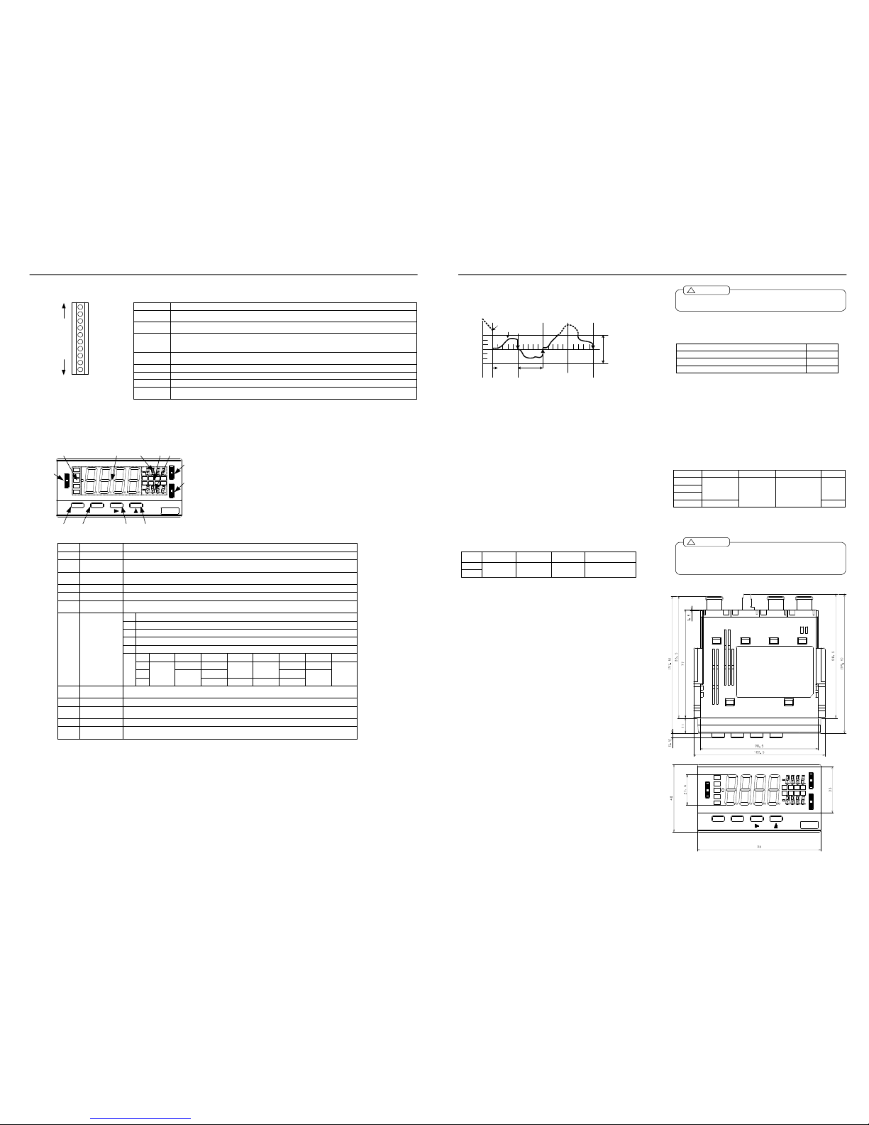
4.1 Display Unit
Names and major functions
①HOLD
②PH
③DZ
④R.RE SET
⑤NC
⑥NC
⑦COM
⑧A.OU T V(+)
⑨A.OU T I(+)
⑩A.OU T COM(-)
Top
Bottom
Termina l Function
S/H
PH
DZ
R.RESE T
"Start/ho ld" contro l termina l. The "hold " state is turned on when this terminal i s at the sa me poten tial as the COM
termina l or short-c ircuited.
"Peak h old" contr ol termina l. The pea k hold func tion is tur ned on wh en this ter minal is a t the sam e potential as the
COM te rminal or short-circu ited.
"Digital zero" con trol termin al. The dig ital zero f unction is turned on when this terminal is at the s ame poten tial as the
COM te rminal or short-circu ited. This setting is valid only when the e xternal co ntrol term inal is sel ected as th e control
method for digital zero using condition data.
"Relay r eset" con trol termin al. The re lay reset f unction is turned on (only for t he meter relay) whe n this term inal is at
the sam e potentia l as the C OM termin al or shor t-circuited .
COM
External control’s common terminals, which are at the sa me potenti al as the L O or AG terminal f or the inp ut circuit.
A.OUT V (+)
A.OUT I(+)
A.OUT COM(-)
Voltage output ter minal of a nalog outp ut.
Current output ter minal of a nalog outp ut.
Common terminal of analog output.
Insulated from inp ut LO or AG termin al/external control CO M termi nal.
⑨ ⑩ ⑪ ⑫
H H
H I
G O
L O
L L
R E P H D Z TZ
M E P 1 P 2 P 3
Enter Mode
④ ⑤ ⑥ ⑦ ⑧
①
②
③
Jog 3
Locatio n Name Major fu nction
①
②
③
Display s results o f judgmen t when u sed with m eter rela y.Judgmen t monito r
Main m onitor Displays a measur ed value, menu na me or a v alue at the time of parameter setting.
Sub mo nitor 1
④
Display s a judgme nt value when used with met er relay; displays a maximu m value, etc. when used witho ut
meter r elay.
⑤
Sub mo nitor 2
Display s a judgme nt value when used with met er relay; displays a maximu m value, etc. when used witho ut
meter r elay.
⑥
⑦
⑧
⑨
⑩
⑪
⑫
Jog 1
Jog 2
Enter
Mode
Shift
Increme nt
Menu a nd value s election a t the time of param eter setti ng; patter n selectio n when us ed with In crement.
Change s judgmen t values w hen used with the m eter rela y; sets a current m easurem ent value to a
judgme nt value; s witching maximum values, e tc. when u sed witho ut meter relay.
Change s judgmen t values w hen used with the m eter rela y; sets a current m easurem ent value to a
judgme nt value; s witching maximum values, e tc. when u sed witho ut meter relay.
Switche s to the p arameter setting m ode.
Change s modes a t the time of param eter sett ing; switch es to the memory mode at t he time o f normal
measur ements (w hen this button is pushed and held.)
Selects digits at the time o f parame ter setting ; DZ contr ol at the t ime of no rmal mea surement s.
Change s values a t the time of param eter setti ng; patter n selection at the ti me of nor mal mea surements
(when t his button is pushed and held ); special operation s
R E
P H
D Z
T Z
M E
P 1
P 2
P 3
Illumina tes when the unit is set to th e remote mode via communic ation fun ction.
Illumina tes when peak hold , valley h old, or pe ak-valley hold is tur ned on.
Illumina tes when Digital Ze ro is turn ed on.
Illumina tes when Tracking Zero is tu rned on.
Illumina tes when Digital Ze ro Backu p is turned on.
P 1
P 2
P 3
Pattern 1 Pattern 2 Pattern 3 Pattern 4 Pattern 5 Pattern 6 Pattern 7 Pattern 8
O F F
O F F
O N
O N
O F F
O F F
O N
O F F O N
O FF
O N
O N
O F F
O N
O F F
O N
Function monitor
8 Output Functions
8.1 Comparison Output Function
The ser ies allows tow judgm ent values of HI, L O to be set up wit h
respect to the m easured valu e (indica ted value) and the judgment
result to be output by relay contact output. For the contact rating, etc.,
see the ou tput specifications.
8.2 Analog Output Function
The series ca n output an analog signal with respect to the indicated
value. There are four types of outputs: 0 to 1V, 0 to 10V, 1 to 5V, and
4 to 20mA, whi ch can be select ed using conditio n data. Als o, any
scaling can be applied.
9 Specifications and External Dimensions
9.1 Input Specifications
9.2 General Specifications
Digital z ero ON. ( T he displ ay is Zero .)
The dis play vani shes to t he correc tion at th e fifth tim es of sam pling be cause
of 3 dig it or less the displ ay.
It doesn 't correct it becau se it com es off fro m the co rrection v alue.
The dis play vani shes to t he correc tion beca use of 3d igit or le ss it.
①
②③
④
⑤
Setting example
Tracking zero co rrection ti me 5( It co rrects it e very five times of samplin g.)
Tracking zero co rrection w idth 3( Correc tion valu e 3digit)
* It beco mes bas ic sampl ing (abou t 960µs)× averag ing times with sam pling.
When the avera ge freque ncy is 5 0 in this example , it becom es a cor rection o f
each a bout 240 ms (abo ut 960µs× 50 time s ×5).
Trackin g
zero sta rt
Five tim es of sa mpling
(Trackin g zero c orrection cycle)
Digital z ero ON
Display value
Trackin g zero wi dth
① ② ③ ④ ⑤
0
-1
-2
-3
1
2
3
(Displa y)
9.3 Output Specifications
9.3.1 Compa rison Output
9.3.2 Analog Output (PWM)
9.4 External Dimensions
The PS voltage must b e applie d or shu t down a t once (n ot gradu ally).
Take a t least a 10-seco nd inter val betw een a s hutdown and sta rtup.
Ca ution
!
10kΩ or more
Load r esistan ceOutpu t type
Resolu tion
:
Maxim um eq uivalent to 14 b its
(I depe nd on o utput indicatio n setti ng.)
Scalin g : Digita l scalin g
Respo nse spe ed
Conve rsion sy stem:PWM conver sion
Accura cy
0 to 1 V
0 to 10 V
1 to 5 V
4 to 20 mA
±(0.5 % of F S)
Appro x. 0.5 s econd
550Ω or less
Ripple
50mVp -p
25mVp -p
(1) Ana log outp ut circui ts and ex ternal co ntrol circ uits are i nsulated.
(withst and volta ge 500V DC, one minute)
(2) CO M termin als of ext ernal co ntrol circ uits and L O termin als of in put
circuits have th e same e lectric p otential a t direct c urrent.
Ca ution
!
Enter Mode
0.5 μV/dig it (Sen sor p owe r : 5V) , 1μV/digit (S ens or po wer : 10V)
:
:
Sensor
power
5V
10V
Zero ad justing
range
-1 to +1 mV/V
Span ad justing
range
1 to +3 mV/V
Measur ement
range
-4 to +4 mV/V
Error
(23℃ ±5℃;35 to 85%)
±(0.1% of FS +2d igit)
Sa mpli ng ra te M axi mum ap prox. 100 0 time s/secon d
Min imu m in put
sen sitivity
:
Sen sor p owe r 5V DC ±5% 60m A, 1 0V D C ±5% 3 0mA
* The e rror is a ppl ied w hen the sa mpli ng ra te is 2 0 time s/second or les s.
Display :
Main displ ay : Red/green 7 -segment disp lay
(character h eight : approx . 20 mm)
Sub displa y : Red 7-segm ent display
(character h eight : approx . 6 mm)
Display ra nge : -9999 to 9999
Operationa l temperature :
:
0 to 50℃ 35 to 85%RH
-10 to 70 ℃ , 60%RH or less
Storage te mperature
External d imension :
48mm (H) x 96mm (W) x 9 9.5mm
Withstand voltage :
PS-input, o utput : 1500V A C, 1 minute
PS-input, o utput : 500V D C, 1 minute
Input-outpu t : 500V DC, 1 minute
AC PS
DC PS
Input-outpu t : 500V DC, 1 minute
Output-outp ut : 500V DC, 1 minute
Output-outp ut : 500V DC, 1 minute
Power sup ply : AC PS
100 to 240V AC ±10%
DC PS
12 to 48V D C ±10%
Power con sumption : A C PS
Maximum lo ad : Approx. 8 VA at 100V AC
DC PS
Maximum lo ad : Approx. 7 W at 24V DC
Weight : Ap prox. 450g
Insulation resistance : AC PS
DC PS
Among the above termina ls : 500V DC 10 0MΩ or more
Among the above termina ls : 500V DC 10 0MΩ or more
Case-PS, in put, output : 1 500V AC, 1 min ute
Case-PS, in put, output : 1 500V AC, 1 min ute
Indicated value > Upper limit judgment value
Conditions for comparison
Hysteresis
: Can be set in the range of 1 to 999 digits for each judgme nt value
Operating speed : Depends on the sampling rate
Judgment value setup range : -9999 to +9999
HI
Lower limit judgment value ≦ Indicated value ≦ Upper limit judgment value
Lower limit judgment value > Indicated value
Judgment result
GO
LO
Contact quantity
Contact rating::
Relay contact ×3
250V AC 2A, 30V DC 2A
●Relay contact output
●Photo coupler output
Output quantity
Contact rating::
Photo coupler ×3
Output rating:Sink current 20mA max. Voltage applied 30V max.
Output saturation voltage: 1.2V or less at 20mA
Page 3

Instruction Manual for MODEL EDI62SInstruction Manual for MODEL EDI62S 10/12 3/12
6 Memory Mode
It is possi ble to display ma ximum value, minim um value, (maximu m
value - minimum val ue) and in put value on the main monitor. Long
pressing the Mode Key results in displaying the maximum value. Press
the Enter Key to return to normal d isplay.
Measured maximum value, minimum value and (maximum value - mini-
mum value) are a lways stored in memory (with the power turned on)
and these data values are cleared by long pressing the Mode Key. In
addition, each of these maximum value, minimum value and (maximum
value - minimum val ue) is displ ayed in red, while the in put value i s
displayed in green.
7 Each Control Functions
7.1 About Each Control Function
If any optional unit is installed, the Start/Hold, digital zero, peak hold
and pattern select control functions can be used. In addition, the digital
zero and pattern se lect functions can be co ntrolled through front key
operation.
* Caution : The COM terminal of the external control circuit and the LO
terminal of the inpu t circuit have the same potential in terms of direct
current .
7.2 Start / Hold Function
The Start/Hold function ho lds the display at any timing, which can be
set in type A or typ e B usin g conditi on data. Type A is the fr ee run
mode, in which you short the S/H terminal with terminal COM or make
these ter minals have th e same potentia l from the free-run status to
hold the indicated value and comparison judgment value. Type B is the
one-shot mode. In this mode, you short the S/H terminal with terminal
COM or m ake these term inals have th e same potent ial from a h old
status to outp ut the indicated val ue and comparison ju dgment value
once. For this, see the timing chart below.
7.3 Digital Zero Function
The Digital Zero functi on is used to set the displayed value to zero at
any timing and then display deviation from that point. Additionally, the
Digital Zero function is activated or deactivated by terminal control o r
through fron t key operation.
* Terminal control or front key opera tion is selected (set) by using
condition data. If the o ptional unit i s not installe d, only the fron t key
operation becomes valid.
7.4 Peak hold Function
The peak h old function is used to hold m aximum value (peak hold),
minimum value ( valley hold), and (maximum value - minimum value)
(peak valley hold ) and generate the outp ut corresponding to each of
these values. In addition, maximum value (peak value), minimum value
(valley hold) or (maximum value - minimum value) (peak valley hold) is
selected (set) b y using condition data. B oth types of peak hold func-
tion are available: Type A and Type B. Type A is of the progressing type
which activa tes the peak ho ld function with the PH terminal shorted
with the COM terminal or the PH and COM terminals set to the same
potenti al to d isplay each of the se measur ed peak values (P H/VH/
PVH). Each peak value is cleared with the PH terminal opened. On the
other hand, Type B is of the result type which conducts measurement
while the PH terminal is shorted with the COM terminal or the PH and
COM terminals are set to the same potential to display, by opening the
PH terminal, each of these measured peak values (PH/VH/PVH) while
the PH terminal is shorted with the COM terminal or these terminals are
set to the same potential.
* If the displayed value overflows during peak hold measure ment, no
overflow display can be released as far as that display is not returned
to normal display once.
7.5 Pattern Select Function
The pattern select function is used to store scaling data and compara-
tor data up to 8 pat terns and be able to set any pattern to be used.
Pattern select contro l selects th e number o f patterns which can b e
used by the pattern select setting in condition data. In addition, I oper-
ate the co ntrol of the patte rn select functi on with front key.
7.6 Tracking Zero Function
The tracking zero function is used to inter nally and digital ly conduct
the a utomatic correcti on of a zero-p oint shi ft. Thi s functi on start s
functioning fro m the time when the digital zero function is activated.
Interna l circuit : P ull-up at a pprox. 5V
(resistance value : ap prox. 10k Ω)
Contro l signal HI level : 4.2 to 5V wit h respect to termina l COM
Contro l signal HI level : 0 to 0.4V wit h respect to termina l COM
Mode
Mode
Mode
Mode
Mode
Mode
Enter
If the m ode key is pushed, it become s
maximu m value d isplay.
*The d isplay cha nges sequ entially.
Max imum → Mnimum → ( M aximum
ーMni mum) → Input → Maxim um
Opera tion Meth od
Measur ement ope ration
The ma ximum va lue is disp layed.
( Red)
The mn imum val ue is displ ayed.
( Red)
The val ue in whic h minimum value is
pulled f rom the m aximum v alue is
display ed.
( Red)
The inp ut value is displayed .
( Green)
All the values are cleared.
*"cLE r" is displa yed in the main mon itor
for abo ut one sec ond.
Display usually.
Push a nd hold( A bout 3 sec onds)
Push a nd hold( A bout 3 sec onds)
Front ke y control :
The dis play at that time is a ssumed to be 0 by pu shing the
shift key for about three sec onds. Digit al zero fun ctions are
released again by p ushing the shift key for three s econds.
Termina l control :
The dis play at that time is a ssumed to be 0 by ma king it to
the term inal DZ, th e termina l COM sho rt-circuit o r this
potentia l. 0 digital functions are release d by openi ng the
termina l DZ.
Opera tion proc edure dia gram (J og lever : Operatio n of front switch c ombinatio n)
●Expla nation of a figure o f jog lever
push tilt downside tilt u pside
1
1 1
Enter
1
1
1
1
1
1
1
1
1
Scaling data patte rn select ion
Compar ator data pattern se lection
1
1
1
1
2or3
Set low layer val ues of the condition data.
Set low layer val ues of the scaling da ta.
Set low layer val ues of the comparato r data.
Judgme nt value s etting
Set a m easured v alue as a reference .
Digit se lection (fr om the
lowest digit to hi ghest digit)
* Retur ns to mea surement
after th e highest digit.
2or3
Pattern selection
+ 2or3
+ 1 or + 1
Norma l operation
1 1
1
1
Shift da ta setting
Digit se lection (fr om the hig hest
digit to the lowes t digit)
2
2 2
Increase or decre ase a valu e.
1
1
Calibra tion data p attern se lection
Set low layer valu es of the Calibratio n data.
* I can set it by v alidating a linearize function b y
conditio n data.
Decreas e a value .
Increase a value.
2or3
2or3
Change the param eter sele cted.
1
1 1
Select a paramet er to chan ge.
Change the param eter sele cted.1
1 1
Select a paramet er to chan ge.
Change the param eter sele cted.1
1 1 Select a paramete r to chang e.
Return s to measu rement
after th e highest digit.
2or3
Mode
Shift da ta is refle cted upon the
measur ement dat a on the M ain Moni tor.
Change the param eter sele cted.1
1 1 Select a paramete r to chang e.
How to set a lo w layer v alue (Co ndition d ata / sca ling data / compar ator data / Calibra tion data)
To chan ge the se lected par ameter, p ush the ce nter of Jo g 1 or us e the Mod e key to m ove from the menu selection
mode t o value ch ange mode .
Select the name of a param eter (sho wn on Sub monitor 2) you wa nt to chan ge by turn ing Jog 1 up or dow n.
11or
Mode
*While Sub mon itor 2 flash es in the menu sele ction mod e, Main m onitor wi ll flash in the value change mo de.
or 1 1 1
Push th e center o f Jog 1 t o choose th e digit yo u want to change, and turn J og 1 up or down to change th e value.
1 1
If the p arameter requires a value ent ry:
Turn Jo g 1 up or down to choose a s election.
If the p arameter requires a selection :
1 or
Mode
Push th e center o f Jog 1 or use the M ode key to shift fr om the va lue change mode to the menu selection mode.
* While Sub mon itor 2 flash es in the menu sele ction mod e, Main monitor w ill flash in the value change m ode.
1 or
Enter
Turn Jo g 1 up or down to select the menu nam e of the p arameter you want to change (shown in Sub mon itor 2) or
return to measur ement by pushing th e Enter ke y.
Front ke y control :
The patt ern can be switched from P-1 to maximu m P-8 by
pushing the increm ent key fo r about th ree second s.
P1
P2
P3
Pattern 1 Pat tern 2 P attern 3 Pattern 4 Pattern 5 P attern 6 Pattern 7 Pattern 8
OFF
OFF
ONONOFF
OFFONOFF ON
OFF
ON
ON
OFF
ON
OFF
ON
Function monitor
Page 4

Instruction Manual for MODEL EDI62SInstruction Manual for MODEL EDI62S 4/12 9/12
* I can set it by v alidating a linearize function by
conditio n data.
Change the param eter sele cted.
Opera tion proc edure dia gram (O peration only with front sw itch)
Enter
Select a paramete r to chan ge.
Change the param eter sele cted.
Select a paramete r to chan ge.
Change the param eter sele cted.
Select a paramete r to chan ge.
Set low layer valu es of the condition data.
Set low layer valu es of the scaling da ta.
Set low layer valu es of the comparat or data.
Setting low layer values of the lineari zed data.
Pattern selection
Mode
Shift d ata is refl ected upon the meas urement
data on the Main Monitor.
Change the param eter sele cted.
Select a paramete r to chan ge.
Memor y mode
Mode
Push an d hold
Push an d hold
Push an d hold
Keep on pushing t he button for autom atic incre ments.
When y ou push th e Mode k ey, mode s will cha nge in the order of the
maximu m value, minimum value, (ma ximum v alue-minim um valu e)
and inp ut value. If you pus h and hold the Mode key whe n you are in
the me mory mod e, all the values in m emory w ill be clea red.
Mode
Mode
Mode
Mode
Mode
Mode
Mode
Mode
Mode
Mode
Digit se lection
Value ch ange
Mode
5.7 Linearization Data Setting Examples
* Linearization data setti ng function
Linearization dat a can be used as a functi on to set 2, 4, 8, or 16 li nearity correction points.
Input data are displayed when the linearization function is OFF. The value to be displayed in response to the input data is output data. For each linearity
correction point, input an d output data must be set.
For example, whe n the linearization f unction is OFF, and you wish to c hange the displayed val ue on the meter from 0 - 1000 to 0 - 1 200, set N01.I
(Correction Point 1 Input Data) and N01.O (Correction Point 1 Output Data) to 0, N02.I (Correction Point 2 Input Data) to 1000, and N02.O (Correction Point
2 Output Data) to 1200.
In this case, the line between Correction Points 1 and 2 behaves according to the linearity correction setting. When the value of the input data exceeds
that at Correction Point 2, the behavior of the output data is no longer affected by the setting (the value of the output data changes from 1200 to 1001).
When more than two co rrection points are set, the behavior of a line connecting two sequential correction points is d ifferent from that of the next two
in sequence.
* Conditions for setting linearization data
To set linearization data, the value of th e input data at one correction point mus t be larger than that at the previous on e.
N01.I < N02.I < N03.I < N04.I ??< N15.I < N16.I
How to calibrat e the zer o input (Z RIN) val ue and th e span in put (SPIN ) value u sing an a ctual loa d or the e quivalen t input
Push th e center o f Jog 1 to choose th e digit you want
to chan ge, and m ove it up o r down to change th e
value. I n the left figure, pus hing the jo g1 while the
least sig nificant d igit of “1.0 00” is se lected, cau ses
the low er digits to also be d isplayed.
Push an d hold the Shift key , then the current
measur ed value w ill be rea d as the se tting.
Equival ent input c alibration
Actual load calibr ation
Push an d hold
1 or
Mode
1 1 1
Caution
* Comp arator jud gment val ues can be set not o nly from J og 2 and J og 3 but also from the low la yers of the comparat or data.
1
1
Press m ultiple tim es
1
1
1
1
1
1
1
Select a digit to change
Increas e a value
Decrea se a value
Mode
Change the selec ted digit
Save an d return to measur ement
Enter
Return to measu rement
Oper ation Met hod
Measur ement op eration
* Not d isplayed u nless the v alue of th e protect l evel param eter of t he conditio n data is PL0.
* Not d isplayed u nless the linearizati on param eter of the condition data is en abled.
Correc tion Point 1 Output D ata Setti ng (setting method i s the sam e as above )
Correc tion Point 2 Input Da ta Setting (setting m ethod is the same as above)
Correc tion Point 1 Input Da ta Setting
Correc tion Point 2 Output D ata Setti ng (setting method i s the sam e as above )
Correc tion Point 16 Output Data Set ting (setti ng method is the sa me as abo ve)
1
* Not d isplayed w hen the va lue of the lineariza tion param eter of th e conditio n data is s maller th an 16.
Page 5

Instruction Manual for MODEL EDI62SInstruction Manual for MODEL EDI62S 5/128/12
0 1 2 3 4 5 6 7 8 9
A B C D E F G H I J K L M N O P Q
R S T U V W X Y Z
-
4.2 Numeric and Character Indications
4.3 Protection Levels
Each parameter of the EDI62S has an individual protection level, and by setting the protection level of the condition data, you can set an access level.
(For the protect level of each parameter, see the P.L. column of the tables in Section 4.4.)
The higher the protection level is, the less the number of settable parameters will be. If you set the protection level to the strictest LV3, you can change
the protection level only, and all the other parameters may not be changed. (No comparator judgment value can be changed using the jog switches in
this cas e.)
*The pr otec tio n l evel set at the tim e of sh ipm ent is LV1. (Se tti ngs of dis play co lor s, s cali ng and jud gmen t-r elate d va lues onl y ar e
avai labl e.)
5.6 Calibration Data Setting Examples
How to calibrat e the zero input (Z RIN) valu e and the span inp ut (SPIN ) value us ing an ac tual load or the equ ivalent in put
Push th e center o f Jog 1 to choose the digit you want
to chang e, and mo ve it up o r down to change the
value. I n the left figure, push ing the sh ift while th e
least sig nificant d igit of “1.0 00” is sele cted, caus es
the low er digits to also be d isplayed.
Push an d hold the Shift key , then the c urrent
measur ed value w ill be read as the set ting.
Equivale nt input c alibration
Actual l oad calibra tion
Push an d hold
Mode
&
* The EDI6 2S series does not add the zer o input value to the span input v alue.
Namely , the gradient an d offset values for y=ax+b are obtained as foll ows:
Gradient (a ) =
(SPAN - ZE RO)
(SPIN - ZR IN)
Offset (b) =
(SPAN - Z ERO) ×ZRIN
(SPIN - ZRI N)
- ZERO
1
Calibration data pattern se lection
Select a pa ttern to set.
* Patterns cannot be selec ted when the nu mber of availab le patterns is se t to 1 using co ndition data.
1 1
1
Sensor pow er supply selec tion
1
1
1 1
1
Zero input value setting1
Mode
1 Select a digit to set.
1 1
Change the value for the s elected digit
(equivalent input calibration ).
the curren t measurement as the setting ( actual load calib ration).
Zero indica tion value settin g1
Mode
1 Select a digit to set.
1 1 Change t he value for the selected digit.
1
1
1
Mode
1
1 1
Change the value for the s elected digit
(equivalent input calibration ).
1
1
Mode
1 Select a digit to set.
1 1 Change t he value for the selected digit.
Select a di git to set.
Operati on Method
Press the Shift key for pro longed time to automatically r ead
the curren t measurement as the setting ( actual load calib ration).
Press the Shift key for pro longed time to automatically r ead
How to set a lo w layer v alue (Co ndition d ata/scali ng data/c omparato r data)
Mode
Mode
Enter
Select the name of a param eter you want to c hange by p ushing the Increme nt key.
Use th e Shift ke y to choos e the digit you want to change , and pus h the Incr ement key to set the value.
If the parameter requires a value ent ry:
Use th e Increme nt key to choose a s election.
If the parameter requires a selection :
Use th e Mode ke y to shift f rom the v alue chan ge mode to the men u selectio n mode.
Use th e Increme nt key to s elect the menu nam e of the p arameter you want to change or return to
measur ement by pushing t he Enter k ey.
To chan ge the se lected par ameter, use the Mo de key to move from the men u selectio n mode to the value
change mode.
&
or
Page 6

Instruction Manual for MODEL EDI62SInstruction Manual for MODEL EDI62S 6/12 7/12
4.4 List of the Parameters
The para meters for the process sign al measurement unit can b e roughly divi ded into thre e types: conditi on data which deal with b asic functions
including sampling time; s caling data which control measure ment including i nput range; com parator data which deal with compa rator output; and
calibration da ta which relating to cal ibration with a sensor.
4.4.1 Condit ion Data
4.4.2 Scaling Data
4.4.3 Compar ator Data
4.4.4 Calibra tion Data
5 Setting Examples and Use Examples
5.1 Scaling Data Setting Examples
Set digital liniter,analog output and decimal point by 4.4.2 scaling data.
Set it in below of operation procedure diag ram.
The digital limiter is the function that limits an input value to the relevant
set value even if a signal higher than or lower than the indicated value
set to DLHI or DLLO respectively is input. The setting condition is DLHI
> DLLO, and if th is condition is not met, Err5 is c aused, returning the
display to DLHI.
5.2 Analog output Scaling Setting Examples
The analog output sets the output value to the display value.
5.3 Comparator Data Setting Examples
● High and Low Judgment Type
The high and low judgme nt type allows you to directly set judgment
values in nu merical values, which are checked against the in dicated
value for judgment. It allows setting of two stages of judgment points: HI
and LO.
* The setting conditions are (HI judgment value - HI hysteresis) > (LO
judgment value + LO hysteresis). If any of these conditions is not met,
Err0 is caused, returning the display to the HI jud gment value setting.
Jog SW 0
P.L.
PH Selec tion 0
Average times
Average times of
moveme nts
Step wid e
Display color type
HI displa y color
GO displ ay color
LO displa y color
Display blank level
DZ backu p
Linearize
TZ time
TZ corre ction rang e
Power on delay tim e
Protectio n level
Unit num ber indic ation
DZ contr ol
0
0
0
1
1
1
1
0
0
0
0
0
0
3
0
0
P.SEL 0
Start/hold type 0
PH type 0
S/H dela y time 0
Setting ra nge or alt ernativesParamet er name
Menu ind ication
Conversi on rate (a verage ti mes of int ernal sam pling; s ampling time: app rox. 1ms ) is selec ted.
Major se tting purpo se and rem arks
Selects t he average times of movemen ts.Filt ering effec ts: Sma ll<1(OFF )-2-4-8-1 6-32>Big
Selects t he range o f display c hanges to maintain image disp lay consi stency .
(If this p arameter i s set to 5, the low est digit w ill displa y either 0 or 5 on ly).
Selects au tomatic (red in th e HI or LO mode or green in t he GO mo de) or manual setting for display c olor type .
Selects r ed or gree n as displa y color at the time of HI judg ment .*Only w hen CLR .T is MAN U.
Selects r ed or gree n as displa y color at the time of GO jud gment .*Only when CLR .T is MA NU.
Selects r ed or gree n as displa y color at the time of LO judg ment .*Only w hen CLR .T is MA NU.
Selects t he display brightnes s. <brig ht OFF- LV1-LV2- LV3-ON >turned o ff
Selects w hether the jog SW i s used or not.
Selects a type that o perates w hen the P H function is turned on (peak hol d/valley hold/pea k-valley hold).
Selects w hether the digital ze ro value i s backed u p or not a t the time when the u nit is turn ed off .
Selects t he number of pattern s availabl e for the p attern sele ction func tion .
Selects w hether the linearize function i s enabled /disab led and s ets the num ber of co rrection p oints .
Selects whether the tracking zero function is enabled/disabled and sets the correction time (setup value/conversion rate).
Sets the t ime betwe en the sta rtup and a ctual star t of measu rements (se tup value x 1 seco nd).
Sets the c orrection range of th e tracking zero func tion .*Only w hen TR.T is set to a value oth er than 000.
Selects t he protecti on level to prevent o peration m istakes .High < LV3-LV 2-LV1-LV 0 >Low
Selects w hether the code of a unit moun ted at the time of st artup is di splayed or not .
Selects a n operatio n type of s tart/ho ld (A: fre e run; B : one shot ).
Sets the d elay time at the tim e of startu p (set up value x 1 ms).
Selects a n operatio n type of p eak hold (A: re al-time di splay; B: results d isplay).
Selects a control method of Digital Zero (SW: front key; TERM: external control terminal).
Initial valu e
(AVG)
(MAV)
(S.WD)
(CLR.T)
(HI.CL)
(GO.CL)
(LO.CL)
(BLNK)
(DZ.BU)
(LINE)
(TR.T)
(P.ON)
(PRO)
(U-NO.)
(S/H.T)
(PVH)
(PS)
(TR.W)
(S/H.D)
(PVH.T)
(DZ.C)
(J.SW)
~
~
~
~
Sets the upper lim it of the displaya ble range .
(Any va lue equal to or exc eeding th e digital limiter H I setting will not be update d and kep t at the s etup valu e .
Selects an analog output r ange .
Sets the relations hip betw een indic ations an d analog outputs .
Sets the position of the de cimal po int.
Sets the lower li mit of the displaya ble rang e.
(Any va lue equal to or belo w the di gital lim iter LO se tting wil l not be u pdated an d kept at the setup value .
1
1
2
1
0
0
Analog o utput HI
Analog o utput LO
Decima l point
Analog o utput type
Digital li miter LO
Digital li miter HI
P.L. Set ting rang e or alter nativesParame ter nameMenu in dication Major se tting pur pose and remarksInitial va lue
(DLHI)
(DLLO)
(AOHI)
(AOLO)
(DP)
(A.OUT )
Each dig it can be set
independ ently
~
~
~
~
(SPIN) S pan inpu t value 2 ~
(ZERO) Z ero in dica tion 2 ~
(SNSR) Senso r pow er sup ply 1
(ZRIN) Z ero in put va lue 2 ~
(SPAN) S pa n indic ation 2 ~
Sele cts a se nsor p owe r sup ply.
Sets the relatio nship betw een in put sig nal s and their in dicatio ns .
P.L. Sett ing range or alternativ esParameter name
Menu indi cation
Major set ting purpos e and rem arksInitial valu e
0
5000
4mA
20mA
10V
20000
-2000
When t he indicati on varies b etween 0 to 5000,
corresp onding ana log output values sh ould be 4 to 20mA .
Analog output
Indicati on value
Example 1
Analog o utput HI ( AOHI)
Analog o utput LO (AOLO)::
5000
0
Example 2
When t he indicati on varies b etween 2 00.0 to -2 00.0,
corresp onding ana log output values sh ould be 0 to 10V.
Analog o utput
Indicatio n value
Analog o utput HI ( AOHI)
Analog output LO (AOLO)::
-2000
2000
Example 1
Above and below set up mode
GO GOHI GO LO
Indication values
Judgment
700
500
0
1000
400
900
200
LO judgm ent value
HI judgm ent value
Hysteresi s range
* The hyst eresis is e ffective ei ther in th e range low er than t he HI judg ment valu e or that h igher tha n the LO
judgment value.
●Tolerance Judgment Type
The tolerance judgment type allows you to set a nominal value and its
tolera nces (XX%) to make judgment on the basis of the jud gment
values calculated fr om these valu es within the instrument. You can
set one nominal value and one tolerance values.
For example, if the nominal value is set t o 1000 and tolerances 10%
respectively, internal judgment values are 1100 for HI judgment value,
900 for LO judgment value.
5.4 How to Switch the Sensor power
5V DC or 10V DC ca n select by 4. 4.4 Calibrati on data. Initi al value
become 5V DC.
5.5 Shift Data Setting Examples
The s hift fun ction allo ws you to arbitrar ily shift the disp lay withou t
changing the inclination of an input s ignal. A setting example below
shows how to shift the in dicated value b y 100 digits.
Example 2
Error judg ment mode
GO GOHI GO LO
Indication values
Judgment
1000
900
0
1100
Nominal v alue
Hysteresis range
Upper side error
Lower side error
* Error is to be set a s a percen tage of th e nominal value.
* The hyst eresis is to be set as an x-th di git of the indication value.
* The hyst eresis is e ffective eit her in the range lowe r than the upper side error or that higher than the
lower side error.
1
1
Press mu ltiple tim es
1
Mode
It is me morized.
Opera tion Meth od
Measure ment ope ration
*It is n ot display ed, except when the
protectin g level of the condi tion data is PL0.
Shift da ta setting
2 2 2oror
2
2
2
The digit is moved , and the d igit
that wan ts to chan ge is sele cted.
Increase a value.
Decrease a value .
Enter
Return t o measure ment
HI judgm ent value
LO judgm ent value
HI logic
LO logic
HI hyster esis
LO hyste resis
Error 1
Nominal value
2
2
2
2
1
1
0
0
Compara tor output type 1
Error 1 h ysteresis 1
GO logic 0
Select ei ther [abo ve or bel ow] or e rror comp arator ty pes.
Sets a H I judgmen t value . *Only w hen COM .T is O/ U.
Sets a LO judgme nt value . *Only w hen COM .T is O /U.
Sets a no minal val ue. *On ly when COM.T is ERR.
Sets an e rror. *O nly when COM.T is ERR.
Sets a H I hysteres is value (smalle r than the setup val ue.) *O nly when COM.T is O/U.
Sets a LO hystere sis value (larger than the s etup valu e.) *O nly when COM.T is O/U.
Sets an e rror hyst eresis ( smaller o r larger t han the se tup value s.) *O nly when COM.T is ERR.
Sets a H I output log ic (N. O.=norma lly open or N.C. =normall y closed)
*Output w hen the p ower is O FF is al ways open .
Sets a G O output l ogic (N .O.=nor mally ope n or N.C .=norma lly closed )
*Output w hen the p ower is O FF is al ways ope n.
Sets a LO output lo gic (N .O.=norm ally open or N.C .=norma lly closed )
*Output w hen the p ower is O FF is al ways ope n.
P.L. Set ting range or altern ativesParameter name
Menu ind ication
Major se tting purp ose and r emarksIni tial value
(LO-L)
(GO-L)
(HI-L)
(ER1.H)
(LO-H)
(HI-H)
(ERR1)
(N.VAL)
(LO-S)
(HI-S)
(COM.T )
~
~
~
~
~
~
~
 Loading...