


L4065 Rev. B 02/14
Index:
Instruction Sheet
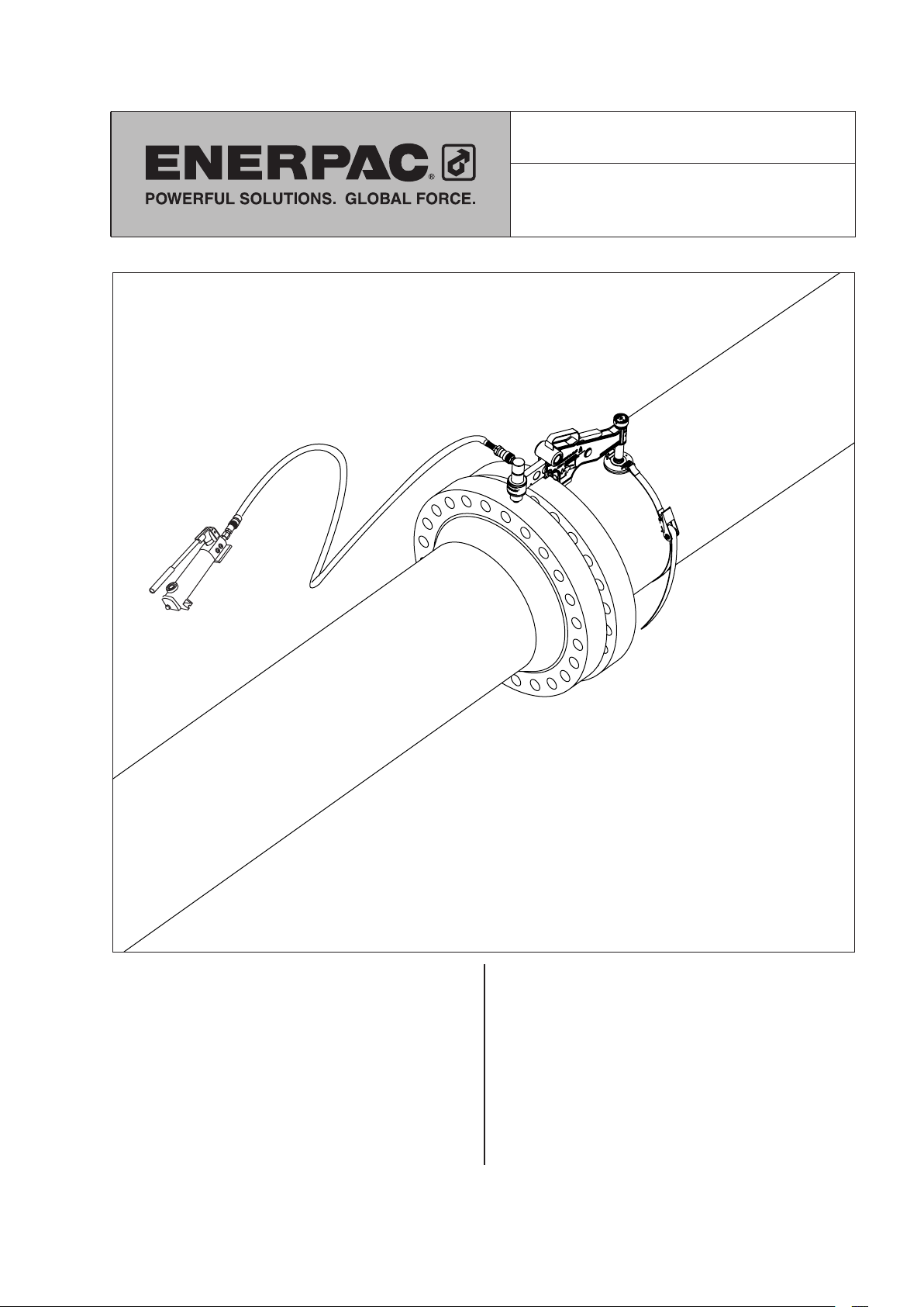
Hydraulic Flange Alignment Tool
Model ATM-9
English ........................... page .......... 1-12
Français ......................... page ........ 13-24
Deutsch ......................... Seite ........ 25-36
Italiano ........................ pagina ........ 37-48
Español ....................... página ........ 49-60
Nederlands ................. pagina ........ 61-72
Norsk .............................. side ........ 73-84
Portugese ................... página ........ 85-96
Chinese ..........................page ...... 97-108
Japanese ........................page .... 109-120
Korean ............................page .... 121-131
Paragraph page
1.0 Receiving Instructions ................ 2
2.0 Safety Issues ....................... 2
3.0 Product Description ................. 2
4.0 Safety Information .................. 3
5.0 List of Equipment ................... 3
6.0 Misalignment Determination ........... 3
7.0 Installation and Operation ............. 4
8.0 Rotational or Twist Misalignment ....... 5
9.0 Dismantling the ATM-9 ............... 5
10.0 Inspection and Examination .......... 6
11.0 Storage .......................... 6
12.0 Lubrication and Maintenance ......... 6
13.0 Troubleshooting ................... 7
14.0 Air Lock Removal .................. 7
15.0 Minimum / Maximum Extension ....... 7
16.0 Application Range ................. 7
17.0 Range of Application Tables ....... 8-10
18.0 Weights and Dimensions ........... 11
11
1.0 RECEIVING INSTRUCTIONS
Visually inspect all components for shipping damage.
Shipping damage is not covered by warranty. If
shipping damage is found notify carrier at once. The
carrier is responsible for all repair and replacement
costs resulting from damage in shipment.
safety first
Read all instructions, warnings and cautions carefully.
Follow all safety precautions to avoid personal injury
or property damage during system operation. Enerpac
cannot be responsible for damage or injury resulting
from unsafe product use, lack of maintenance or
incorrect product and/or system operation. Contact
Enerpac when in doubt as to the safety precautions
and applications. To protect your warranty, use only
ENERPAC hydraulic oil.
CAUTION: Make sure that all system
components are protected from external
sources of damage, such as excessive heat,
flame, moving machine parts, sharp edges and
corrosive chemicals.
CAUTION: Avoid sharp bends and kinks
that will cause severe back-up pressure in
hoses. Bends and kinks lead to premature
hose failure.
WARNING: Immediately replace worn or
damaged parts with genuine Enerpac parts.
Enerpac parts are designed to fit properly
and withstand rated loads.
WARNING: Always wear safety glasses. The
operator must take precaution against injury
due to failure of the tool or workpiece
A CAUTION is used to indicate correct operating or
maintenance procedures and practices to prevent
damage to, or destruction of equipment or other
property
A WARNING indicates a potential danger that requires
correct procedures or practices to avoid personal
injury.
2.0 SAFETY ISSUES
Failure to comply with the
following cautions and warnings
could cause equipment damage
and personal injury.
IMPORTANT: Minimum age of the operator
must be 18 years. The operator must have
read and understood all instructions, safety
issues, cautions and warnings before starting to operate
the Enerpac equipment. The operator is responsible for
this activity towards other persons.
WARNING: To avoid personal injury and
possible equipment damage, make sure all
hydraulic components withstand the
maximum pressure of 10,000 psi [700 bar].
DANGER: Do not handle pressurized hoses.
Escaping oil under pressure can penetrate
the skin, causing serious injury. If oil is
injected under the skin, see a doctor immediately.
WARNING: Never pressurize uncoupled
couplers. Only use hydraulic equipment in a
coupled system.
IMPORTANT: DO NOT lift hydraulic
equipment by the hoses or couplers. Use
the carrying handle or other means of safe
transport.
We recommend the use of special loosening
liquids or sprays. Enerpac hydraulic torque
wrenches offer both square and hexagon
drive units to loosen or tighten bolts and nuts. Enerpac
offers nut splitters in case a nut can not be removed.
3.0 PRODUCT DESCRIPTION
The ATM-9 Alignment Tool is intended for use in typical
maintenance and installation procedures. It allows the
realignment of misaligned flanges within a 9 Ton [90 kN]
physical capacity. For example, it may be used to assist
in the replacement of ring and other type joints.
IMPORTANT: Minimize the risk of
overloading. Use hydraulic gauges in each
hydraulic system to indicate safe operating
loads. It is your window to what is happening in the
system.
WARNING: Do not overload equipment.
Overloading causes equipment failure and
possible personal injury.
The ATM-9 is a hydraulically operated tool actuated
by a hydraulic cylinder and hand pump. The maximum
operating pressure is 10,000 psi [700 bar].
The use of these instructions will promote the safe use
and maximum service life of the tool. All sections of this
instruction sheet should be read prior to using the tool.
22
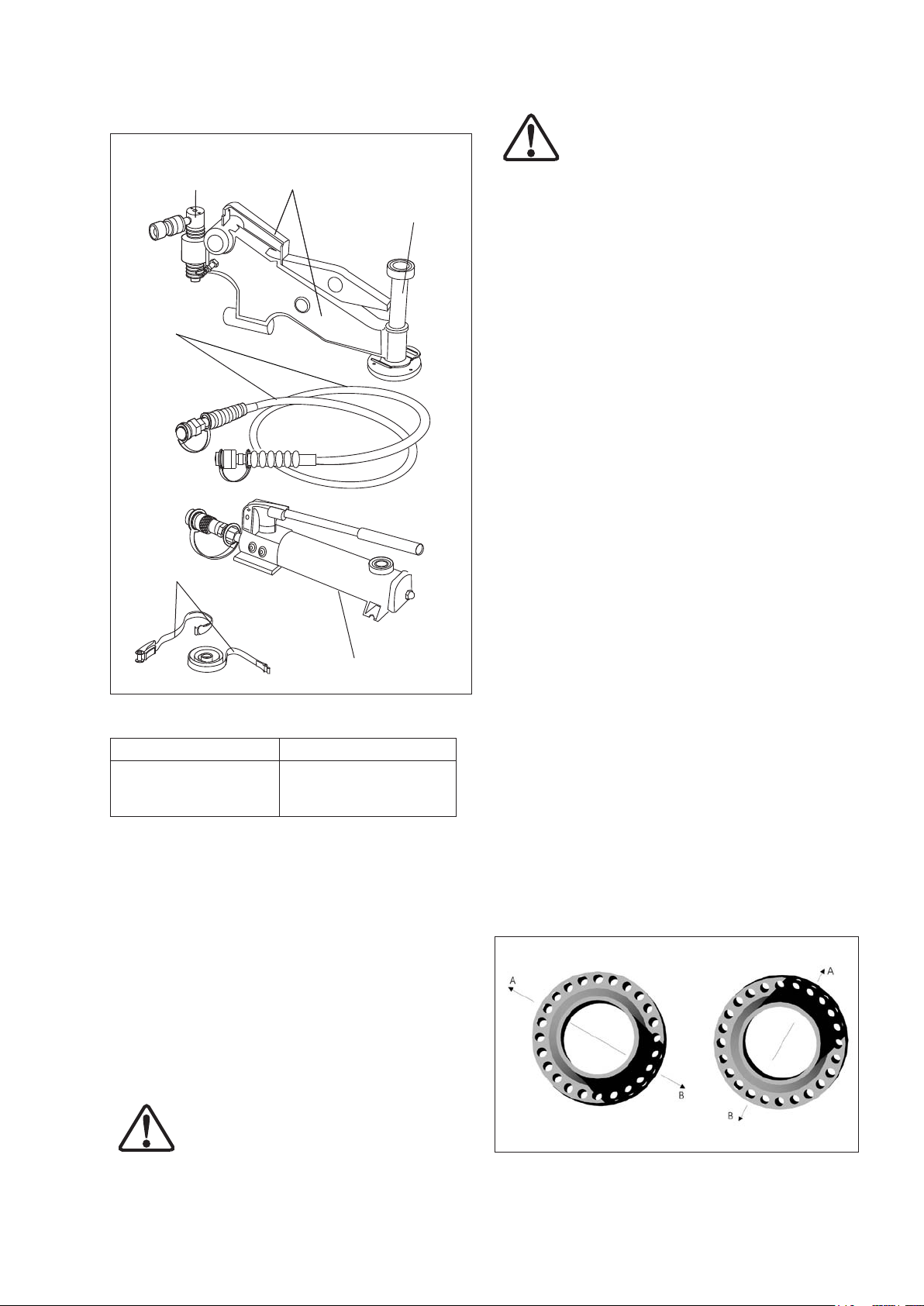
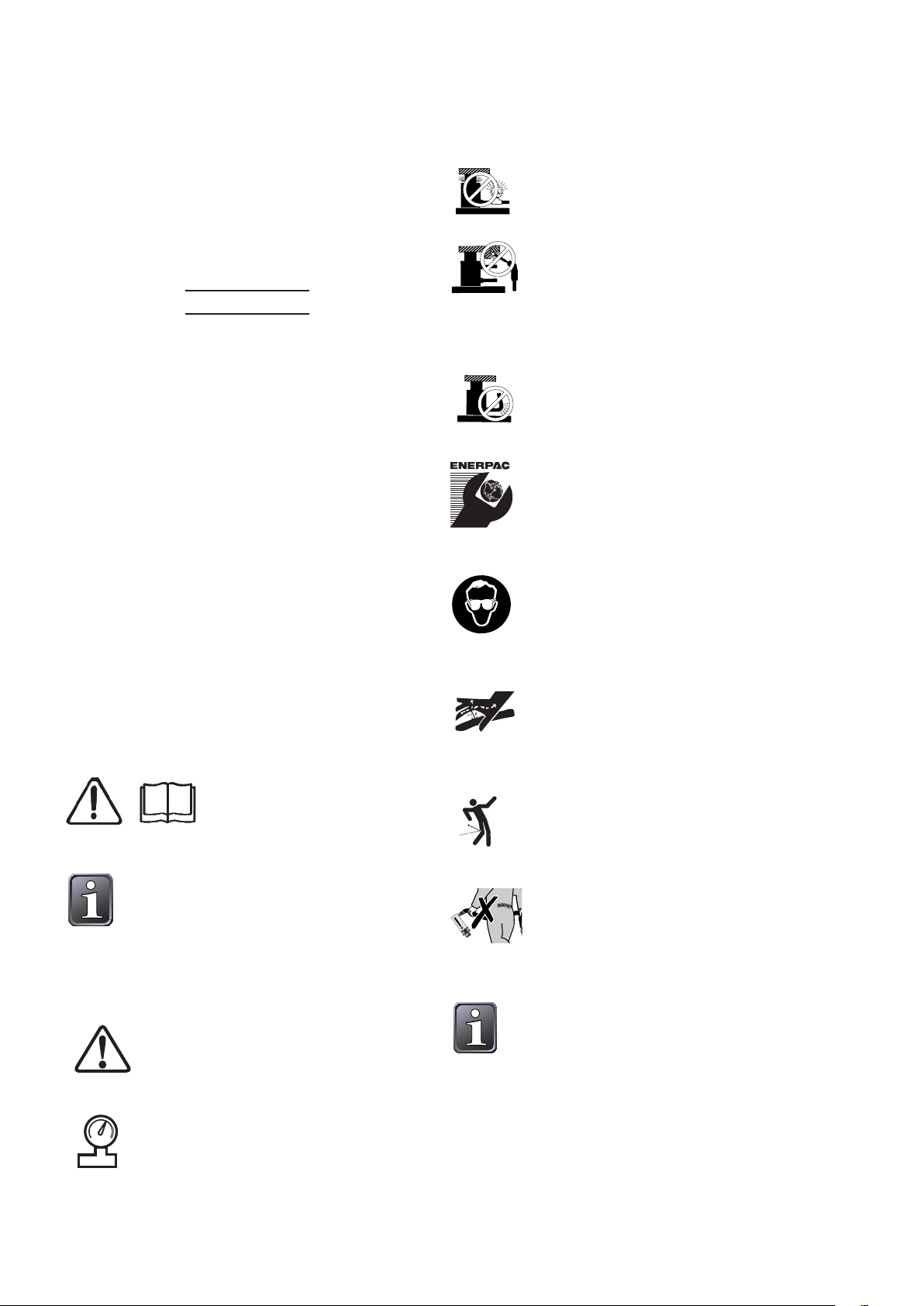
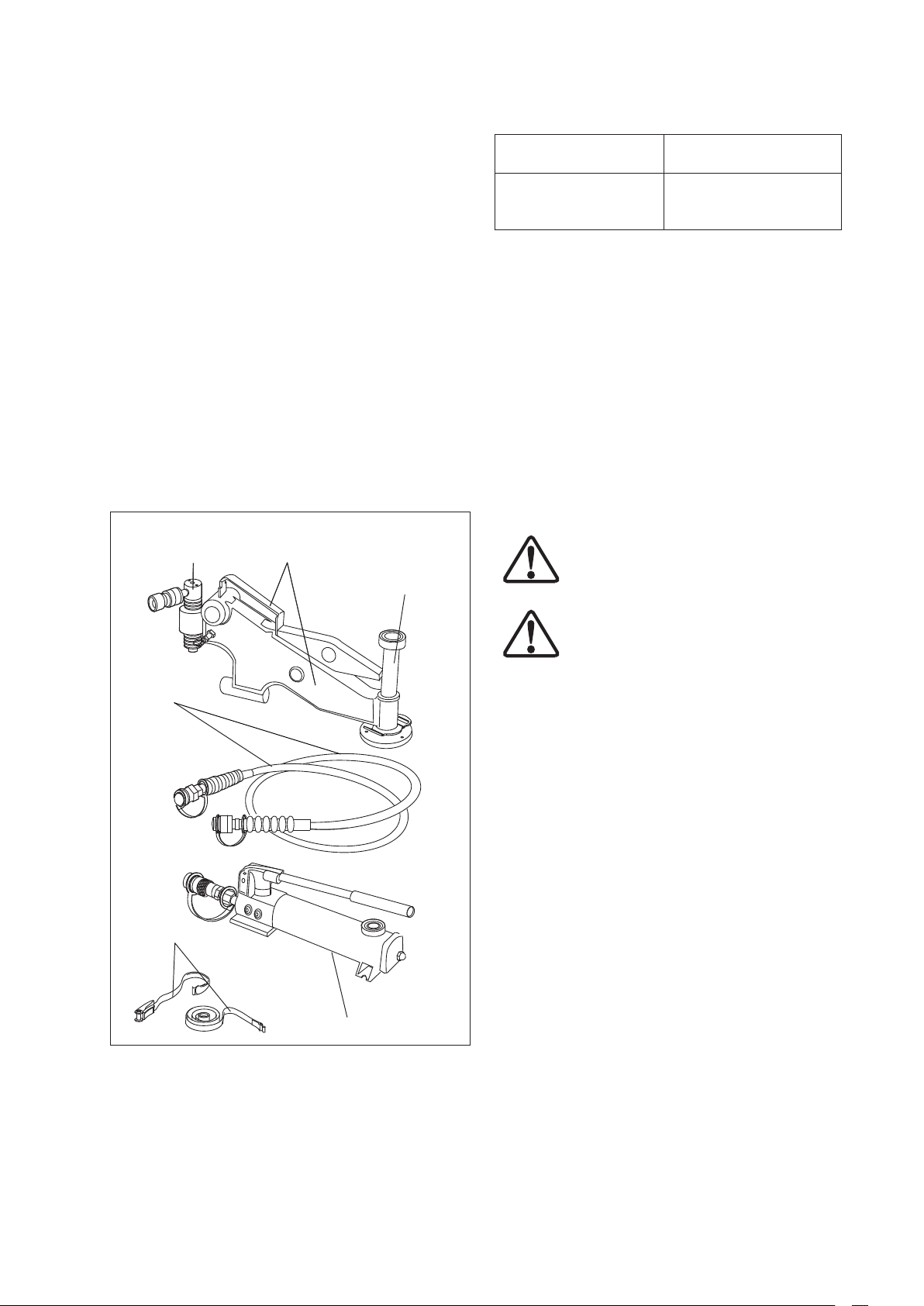
3.1 Major Features and Components
Fig. 1
Hydraulic
Cylinder
Hydraulic
Hose
ATM-9
Tool
Drop Leg
WARNING: Never attach the ATM-9 to a
joint until after the flange bolts have been
loosened and removed. Overloading may
occur if bolts are removed while the tool is installed,
and the resulting force is greater than the safe working
load of the tool.
5.0 LIST OF EQUIPMENT
The tool set includes:
• ATM-9 alignment tool with hydraulic cylinder.
• Hydraulic hose, 6 feet [1,8 m] long.
• P-142 hydraulic hand pump.
• 3/8 inch NPTF couplers on hose, cylinder and pump.
• Ratchet and strap.
• Instruction sheet.
• Carrying case.
Note: All hydraulic components are rated for 10,000
psi [700 bar] operation.
6.0 MISALIGNMENT DETERMINATION
PROCEDURE
Strap
P-142 Hydraulic Pump
3.2 Technical Data
Tool Description: Aligning Force:
Hydraulic fixed flange
and rotational alignment
tool.
Note: Refer to section 18.0 for weights and dimensions.
9.0 T [90 kN]
from 10,000 psi [700 bar]
of hydraulic pressure.
4.0 SAFETY INFORMATION
IMPORTANT: In all installations the site safety
requirements must be adhered to. The safety of the
operator and any assisting personnel is of paramount
importance along with the safety of others including the
general public.
• The ATM-9 must not be attached to a flanged joint
prior to the misalignment determination procedure
being carried out.
Refer to warning statement in
section 4.0.
• Every second bolt should be loosened and removed.
Continue with this procedure. Misalignment may
not occur until only a few bolts remain. At this point
the direction of any misalignment should become
obvious.
• The ATM-9, once attached, will directly push against
the misalignment, bringing the joint back into
alignment.
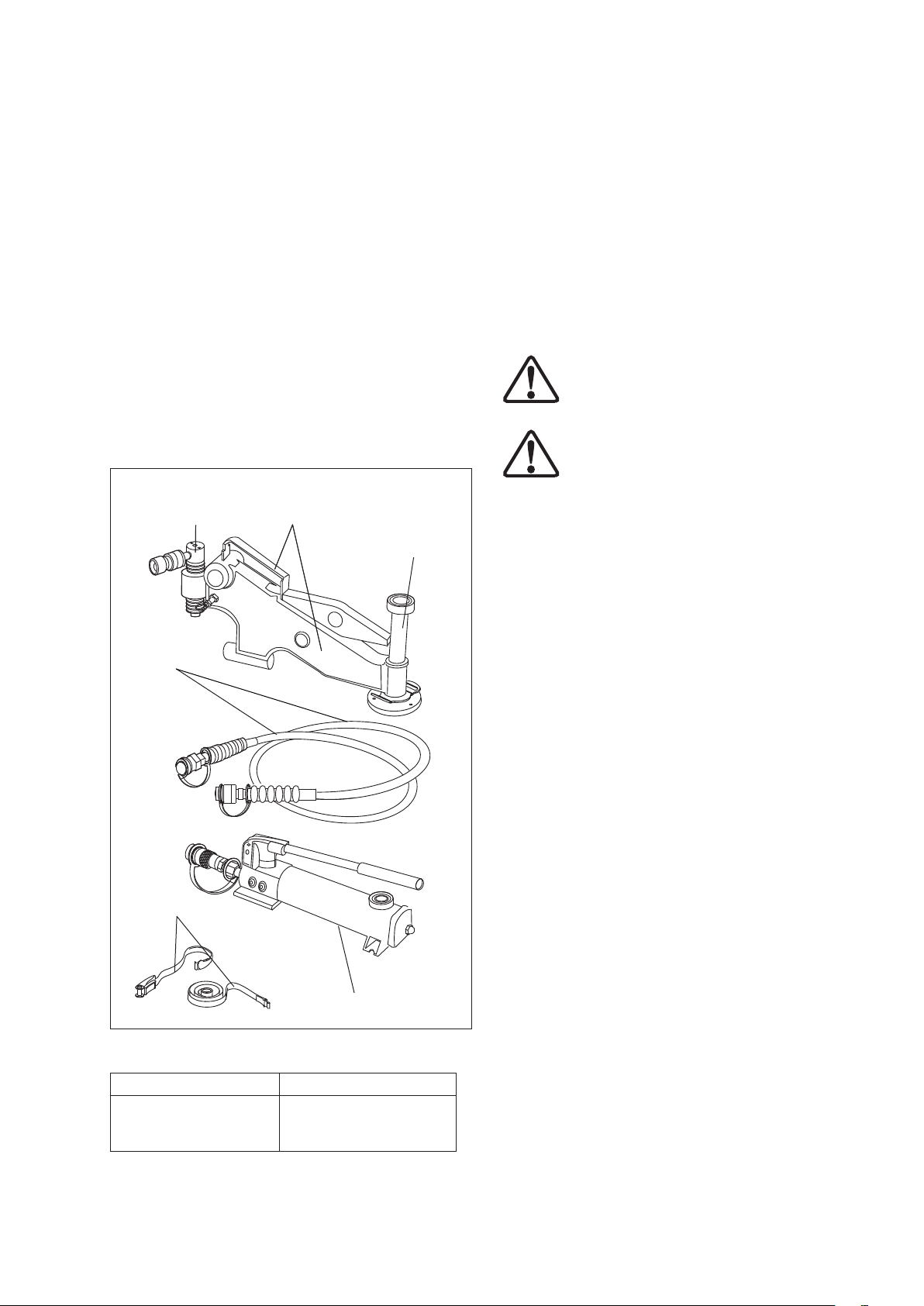
Example: Misalignment in various directions
A flanged joint, once broken down, may spring out of
alignment at any point, or in any direction around.
See Fig. 2. The ATM-9 should be attached at the
maximum point of misalignment i.e. A or B. Each
example shows where ATM-9 should be attached.
Fig. 2
These instructions are intended only to cover the safe
operation of ATM-9 during a normal maintenance and
installation operation. All other safety aspects must be
controlled by the operation supervisor.
CAUTION: The ATM-9 must not be attached
to pressure vessel nozzles.
33
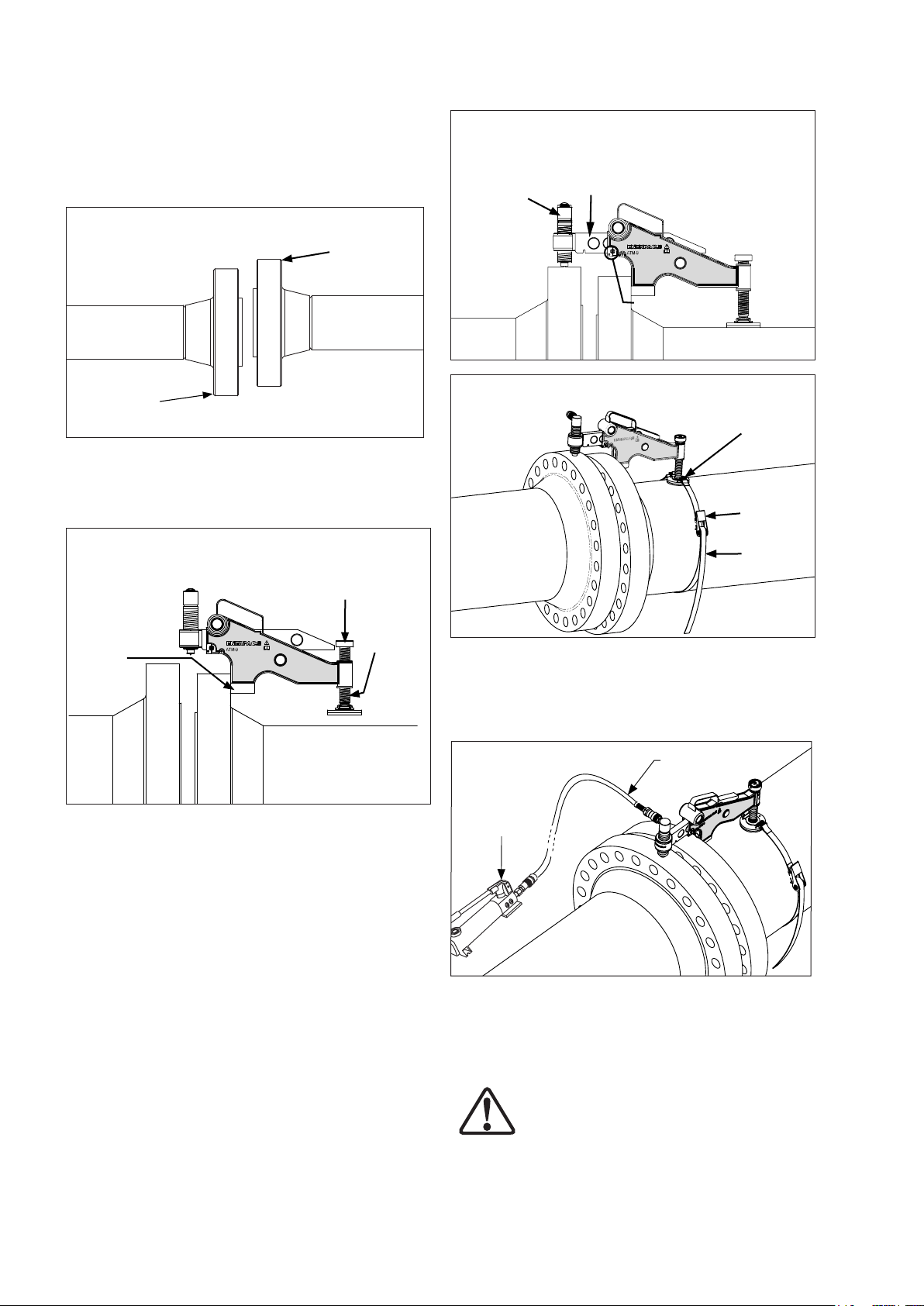
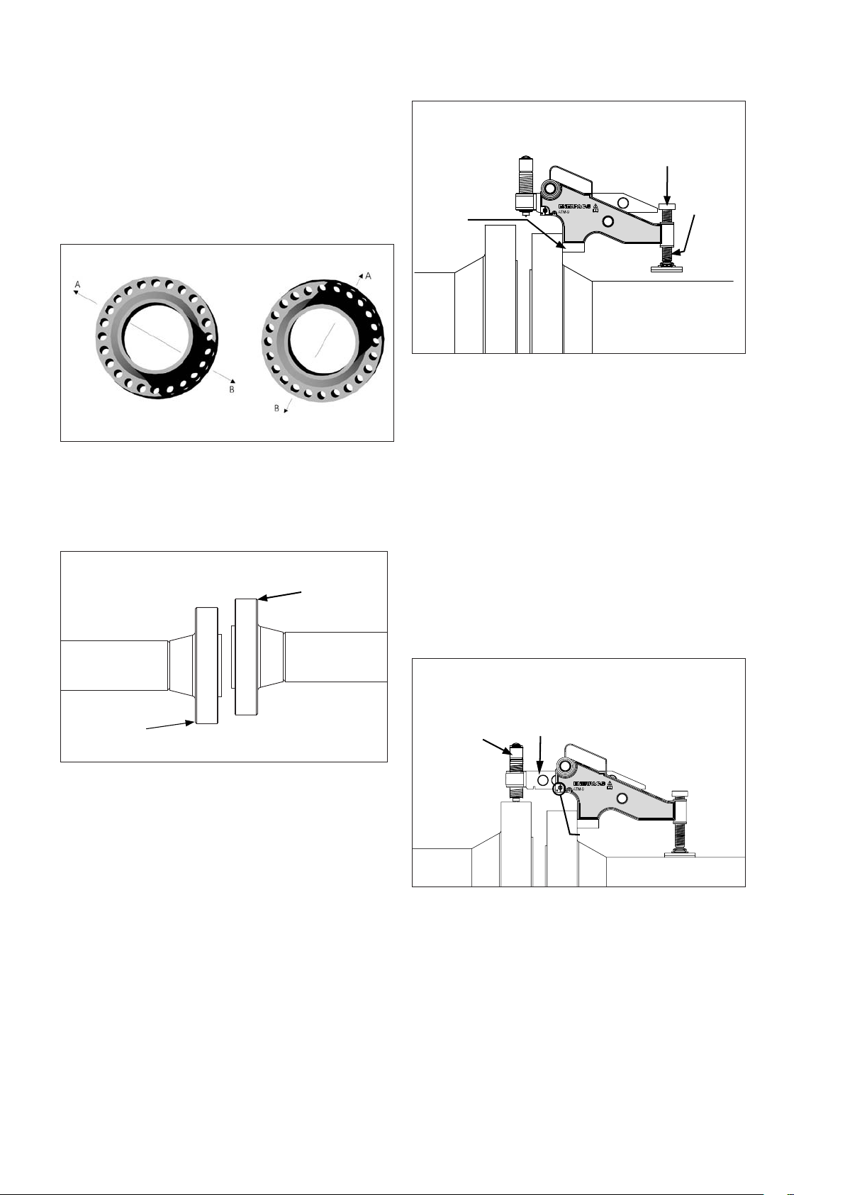
7.0 INSTALLATION AND OPERATION
1. Determine the maximum points of misalignment.
(see Fig.3). The maximum points are on the top or
bottom of the joint, as illustrated by the arrows.
Fig. 3
Point of Max.
Misalignment
Fig. 5
Hydraulic
Cylinder
Wing
Wing Lock Pin
Point of Max.
Misalignment
2. Guide the lift hook of the tool into the bolt hole at the
maximum point of misalignment. Then, adjust the
drop leg down onto the pipe by turning the adjusting
knob in the clockwise direction (see Fig.4).
Fig. 4
Adjusting
Knob
Drop
Lift Hook
Leg
Note: The tool should be held up level within the bolt
hole during adjustment. The tool must remain parallel to
the pipe at all times.
Fig. 6
Buckle
Ratchet
S trap
5. Connect the P-142 hydraulic pump to the hydraulic
hose, and the hose to the hydraulic cylinder. Operate
the pump handle until the joint comes into alignment.
(see Fig.7).
Fig. 7
Hydraulic
Hand Pump
Hydraulic
Hose
3. Pull out the lock pin and extend the wing out to the
desired distance (see Fig.5). Rotate the cylinder
clockwise until it locates onto the surface of the
opposite flange. At this stage, ensure that the tool is
sitting level and that the end of the cylinder is in full
contact with the surface of the higher flange.
4. Attach the hook of the strap through one of the slots
on the buckle (located above the drop leg pad).
Place the hook of the ratchet through the other slot
on the opposite side of the buckle. Feed the end
of the strap through the ratchet and tighten. (see
Fig.6).
4
Note: The ATM-9 hydraulic cylinder is rated at 10,000
psi [700 bar] operating pressure. The P-142 hydraulic
pump contains a built-in safety relief valve that opens
at approximately 10,500 psi [724 bar].
WARNING: If a different pump is used in
place of the P-142 for any reason, be certain
that the pump relief valve is not set higher
than 10,500 psi [724 bar]. Install a pressure gauge in
the circuit to monitor system pressure.
6. When alignment is completed, the flange bolts may
be inserted and tightened. After replacing all of the
bolts in all open bolt holes (except for the bolt hole in
which the tool lift hook is inserted), remove the tool
by reversing steps 1 through 5.
CAUTION: Open pump release valve and be
sure that all hydraulic pressure is relieved
before disconnecting any hoses or fittings.
7. After removing the tool from the flange, insert and
tighten the last flange bolt in the remaining bolt hole.
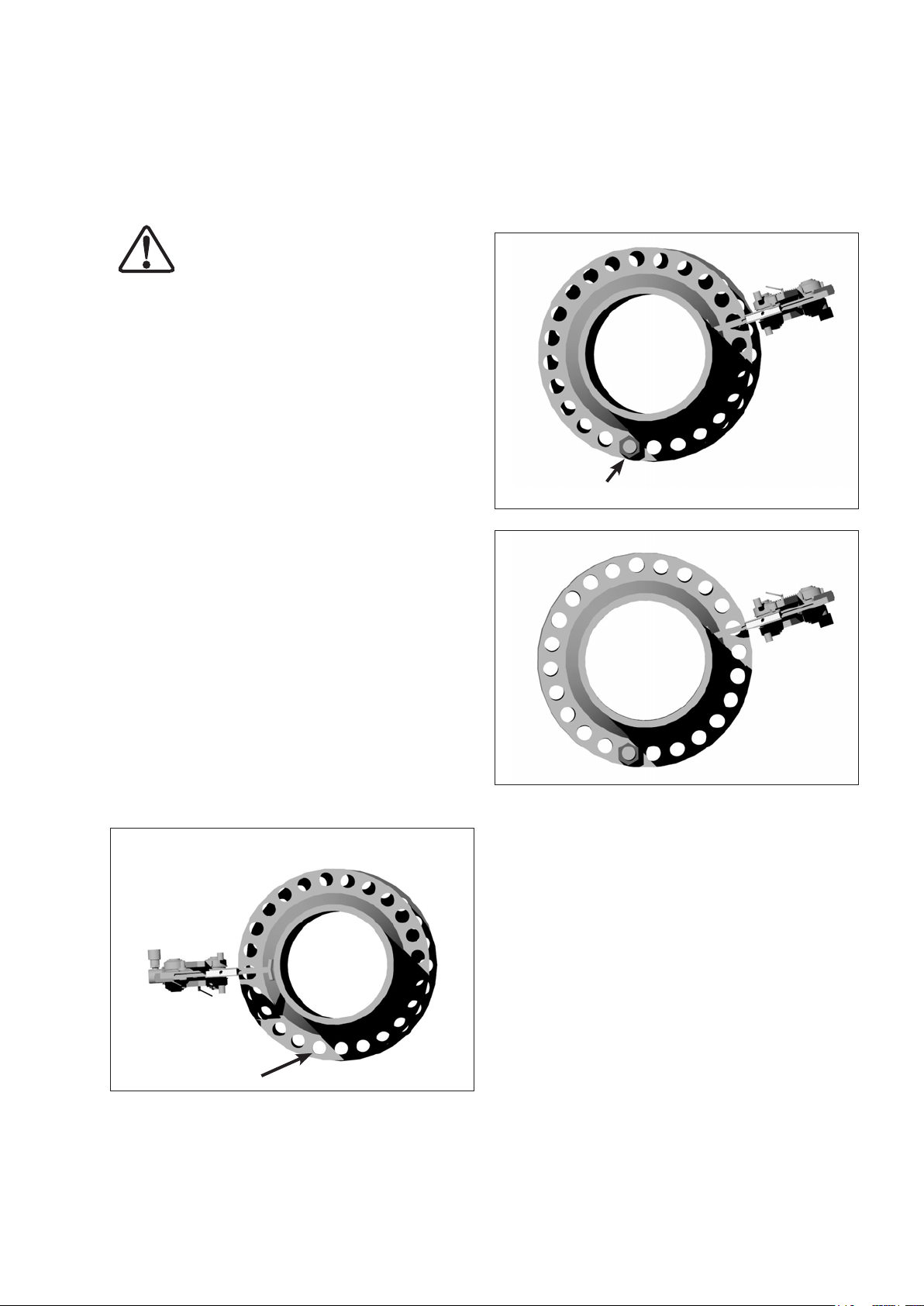
8.0 ROTATIONAL OR TWIST MISALIGNMENT
This is a common problem on both onshore and
offshore pipeline installations (see Fig. 8). Quite often
the flanges are in alignment but the operator is unable
to fit the bolt into any two corresponding bolt holes on
the joint‘s circumference. The ATM-9, with its 90 kN [9
ton] capacity, has the ability to manipulate the flanges
in various directions.
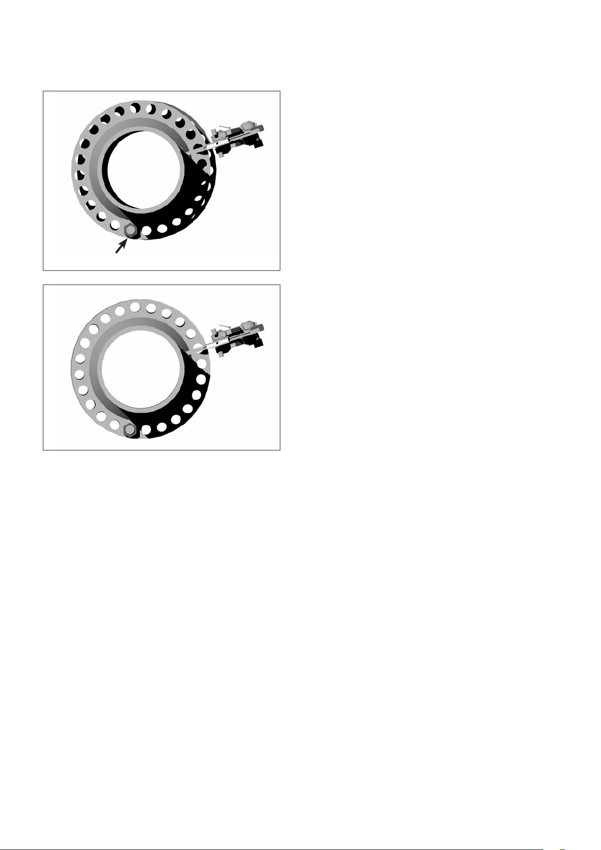
4. The ATM-9 can then be attached at another point on
the joint‘s circumference (see Fig. 9) pushing against
the inserted bolt. Advance the hydraulic cylinder until
another, or all the bolt holes are parallel (see Fig. 10).
5. Once the remaining bolts are inserted, the ATM-9
can be removed.
Fig. 9
A
The set-up procedure is the same as before with one
possible exception. The ATM-9 can be attached to
the most accessible point on the joint‘s circumference
because the misalignment occurs at all bolt holes to the
same degree.
8.1 The recommended operating procedures are:
1. Select the most convenient or accessible point on
the joint‘s circumference and attach the tool there.
(Follow steps 1 thru 5 in section 7.0).
2. In the situation when both flanges are aligned but
rotational misalignment is present the ATM-9 is used
to push the flanges beyond alignment until one pair
of bolt holes become parallel (see point A in Fig. 8).
Fig. 8
A
3. Insert the bolt into the bolt hole at point A and
then release ATM-9. The load will transfer onto the
inserted bolt.
Fig. 10
Please note that in some situations the operator may
have to ‘chase’ the misalignment around the joint‘s
circumference and attach the ATM-9 at several different
positions to rectify the misalignment. On each occasion
the procedures outlined in steps 1 to 7 in section 7.0
should be followed.
9.0 DISMANTLING THE ATM-9
• Once alignment is achieved, all work on the joint
finished, and bolt-up completed (apart from the bolt
hole in which the ATM-9 is located), the tool can be
removed from the joint by reversing steps 1 thru 5 in
section 7.0.
• Care should be taken not to drop any of the
component parts when removing them from the
aligned joint. This action will prevent injuries
personnel.
Note: Refer to the ATM-9 repair parts sheet for
complete parts list and assembly diagrams.
55
10.0 INSPECTION AND EXAMINATION
Fig. 11
• After finishing the job and before the ATM-9 is
placed back into service, the completeness of the
tool must be established and items examined to
ensure that they are serviceable.
• Any missing or damaged items are to be replaced
as soon as possible and prior to the tool being
used again.
• Grease all moving parts regularly. Refer to section
12.0, Lubrication and Maintenance.
• Cap or plug all open hydraulic fittings to prevent
dirt entry. Be sure that pump air vent cap is in the
“closed” position.
• Ensure rollers and pins remain grit free.
• Return all items to the carrying case when not in
use.
11.0 STORAGE
• Cap or plug all open hydraulic fittings.
• Smear machined surfaces with grease.
• Store the ATM-9 in a cool dry place.
12.0 LUBRICATION AND MAINTENANCE
Use Mobilgrease XHP ™ 222 Special grease or an
equivalent
good quality high load bearing grease
.
Always ensure that the wing of the tool is grit-free and
that the rollers rotate freely and are well lubricated (see
Fig. 13). This will enhance the tool’s performance and
help prolong its service life.
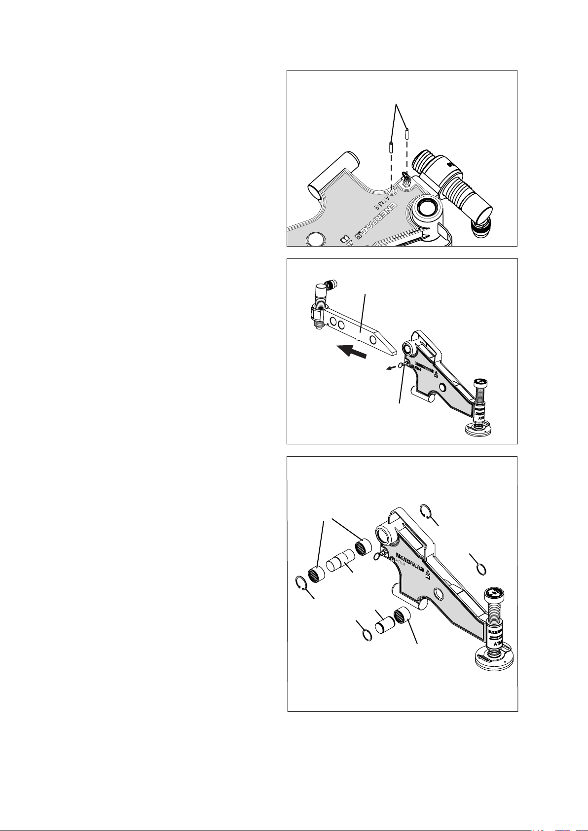
Clean, inspect and lubricate the ATM-9 as described in
the following steps:
Spring Pins
Fig. 12
Wing
Wing Lock Pin
Fig. 13
STEP 1. Place tool flat on work bench.
STEP 2. Remove two spring pins on the front of the
main body
(see Fig. 11)
.
STEP 3. Pull the wing lock pin out. Remove the
wing from the main body by sliding it
forward
(see Fig. 12)
.
STEP 4. Remove the circlips using a circlip pliers
(see Fig. 13).
STEP 5. Slide the roller shafts out in order to remove
the rollers and bearings for examination.
(see Fig. 13).
STEP 6.
Inspect the roller shafts, rollers and bearings
for damage, If there is no damage present,
then these parts can be cleaned, greased and
reassembled (reverse steps 1 through 5).
1
2
1. Rollers and Bearings
2. Circlips
3. Roller Shafts
66
2
2
3
3
2
1
13.0 TROUBLESHOOTING
Problem 1:
The hydraulic cylinder is sliding on the circumference of
the opposite flange as the ATM-9 is aligning the joint.
4. Stand the tool on a level surface, hold the hydraulic
pump above the tool, close the release valve on the
pump, and prime the pump to advance the hydraulic
cylinder until the cylinder is fully advanced and a
small pressure is achieved.
Cause:
Grit or dirt on wing, rollers or bearings, wing is at full
extension.
Solution:
A. Ensure the rollers are rotating freely and that there is
no restriction to the rollers on the wing surfaces such
as dirt or grit.
B. Check that the wing is not at full extension when
aligning the joint.
C. Ensure that there is enough extension left to allow
the ATM-9 to expand as the joint is aligned.
Problem 2:
The ATM-9 is attached and appears to be functioning
properly, but the joint will not align.
Cause:
A. There may be air in the hydraulic system restricting
the force on the flanges.
B. There may be something restricting the joint at a
point close to the flanges. The joint may require more
than 9 ton [90 kN] pressure to align.
Solution:
A. See air lock removal instructions in section 14.
B. Check the area around the joint to establish if there
is an obstruction to the joint.
C. If the joint requires more force than that of the 9 ton
[90 kN] capacity of the tool, then another method to
align the joint should be adopted.
14.0 AIR LOCK REMOVAL
Remove air as described in the following steps:
1. Remove the air vent cap on top of the hydraulic
pump and check hydraulic oil level to ensure there is
enough oil to advance the cylinder.
5. With the hydraulic pump held above the tool, open
the release valve allowing the cylinder to retract fully
back. While the cylinder is retracting any air that is
within the system will be forced up to the pump and
vented out through the air vent cap.
6. Repeat the above procedure three or four times to
ensure that all air is removed and the tool will reach
full working pressure.
15.0 MINIMUM / MAXIMUM EXTENSION
Refer to section 18.0, Weights and Dimensions, for
minimum and maximum extension information.
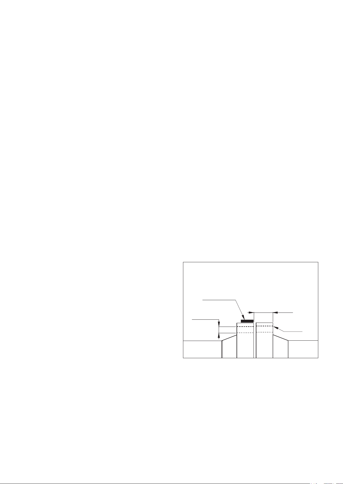
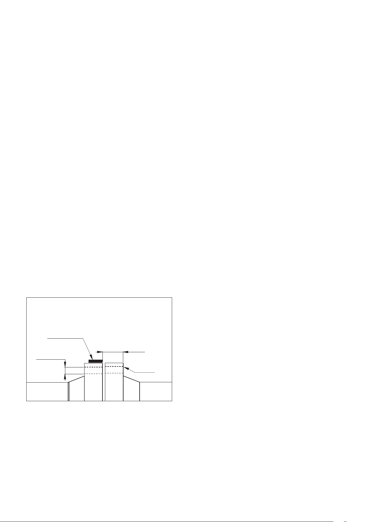
16.0 APPLICATION RANGE
Two basic dimensions, A and B, will determine if the
ATM-9 can be used to align the joint. If the flange joint
to be aligned is between 3.66 inch [93 mm] and 9 inch
[228 mm] as illustrated by (A), has a bolt hole size of
1.24 inch [31,5 mm] or greater (B), then the ATM-9 can
be attached and alignment achieved (see fig. 14).
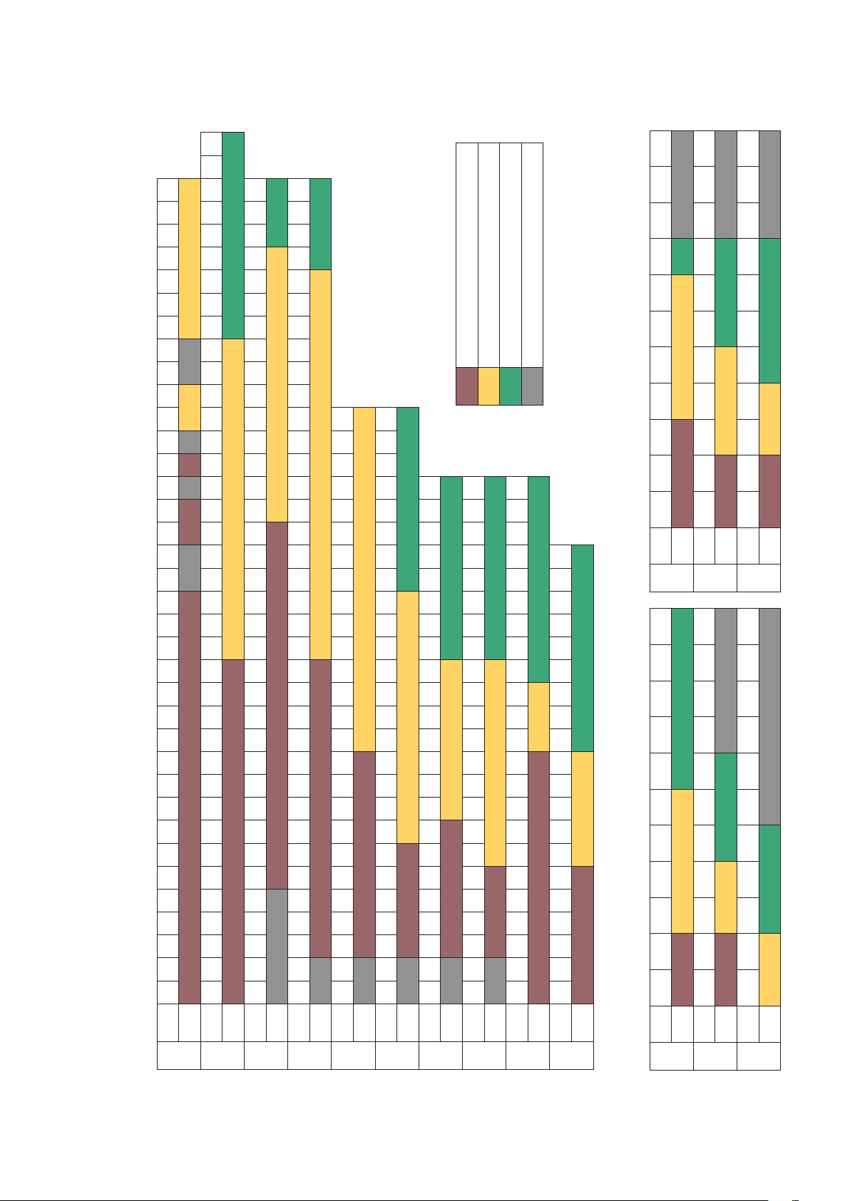
See charts in section 17: by flange type, class and
diameter.
Fig. 14 – Min. and max. flange sizes (visual)
Saddle of hydraulic
cylinder must rest fully on
the circumference of the
flange to be pushed.
Min. distance 3.66 inch [93 mm]
Min. bolt hole size
1.24 inch [31,5 mm]
B
Max. distance 9 inch [228 mm]
A
Hook into this
bolt hole
2. Replace air vent cap, but do not tighten the cap.
The cap must remain loose (in the “vent” position) to
allow air to enter and leave the pump during use. The
cap should only be tightened fully when the tool is to
be returned to the carrying case after use.
3. With the air vent cap loose, connect the pump to
the tool with the hydraulic hose supplied within the
carrying case.
77

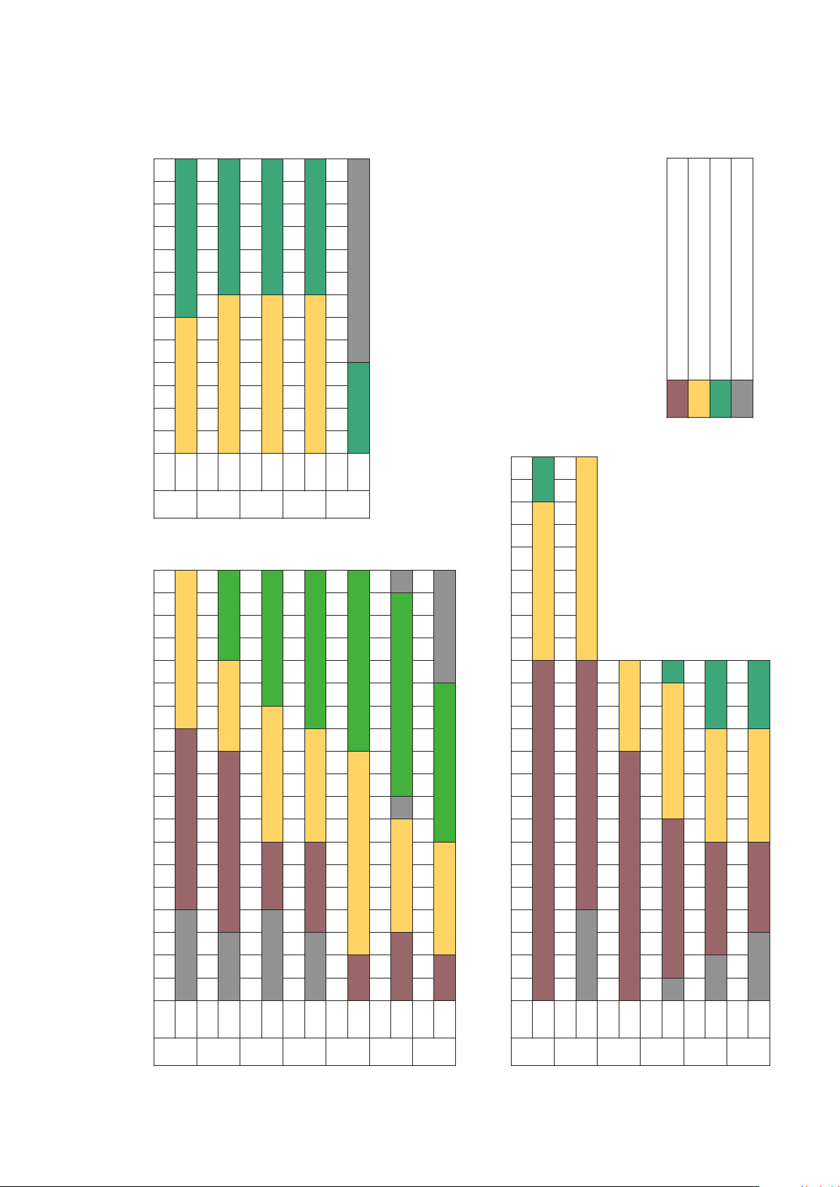
ATM-4 ATM-4
ATM-2
SUITABLE FOR ENERPAC ATM-2 TOOL
SUITABLE FOR ENERPAC ATM-4 TOOL
SUITABLE FOR ENERPAC ATM-9 TOOL
NOT SUITABLE FOR ANY ENERPAC ATM TOOL
Note: Models ATM-2 and ATM-4 shown for reference purposes only.
3K
TOOL ATM-2 ATM-4 ATM-9
CLASS
NPS 2 1-16" 2 9-16" 3 1-8" 4 1-16" 5 1-8" 7 1-16" 9" 11" 13 5-8" 16 3-4" 21 1-4"
6K
TOOL ATM-2 ATM-4 ATM-9
CLASS
NPS 2 1-16" 2 9-16" 3 1-8" 4 1-16" 5 1-8" 7 1-16" 9" 11" 13 5-8" 16 3-4" 21 1-4"
5" 6" 7" 8" 9" 10" 11" 12" 13" 14" 15" 16"
4
4"
3
4" 5" 6" 7" 8" 9" 10" 12" 13" 14" 15" 16" 17" 18" 19" 20"
4" 5" 6" 7" 8" 9" 10" 12" 13" 14" 15" 16" 17" 18" 19" 20" 21" 22" 23" 24" 27" 29" 30" 33" 35" 36" 39" 42" 45" 48"
3
3"
2
2"
4" 5" 6" 7" 8" 9" 10" 12" 13" 14" 15" 16" 17" 18" 19" 20" 21" 22" 23" 24" 26" 27" 29" 30" 33" 35" 36" 39" 42" 45" 48" 54" 60" 66" 72"
3
1/2"
1
1
1/2"
1/2"
1/2"
1/4"
4" 5" 6" 7" 8" 9" 10" 12" 13" 14" 15" 16" 17" 18" 19" 20" 21" 22" 23" 24" 27" 29" 30" 33" 35" 36" 39" 42" 45" 48"
4" 5" 6" 7" 8" 9" 10" 12" 13" 14" 15" 16" 17" 18" 19" 20" 21" 22" 23" 24"
3
2
1
1
3"
2"
1/2"
1/2"
1/2"
1/4"
3
2
1
1
3
1/2"
3"
2
1/2"
2"
1
1/2"
1
1/4"
4" 5" 6" 7" 8" 9" 10" 12" 13" 14" 15" 16" 17" 18" 19" 20" 21" 22" 23" 24"
3"
2"
1/2"
1/2"
1/2"
1/4"
3
3"
2
2"
1
1
1/2"
1/2"
1/2"
1/4"
4" 5" 6" 7" 8" 9" 10" 12" 13" 14" 15" 16" 17" 18" 19" 20"
3
3"
2
2"
1
1
1/2"
1/2"
1/2"
1/4"
3"
2
2"
1
1
1/2"
1/2"
1/2"
1/2"
1/4"
5" 6" 7" 8" 9" 10" 11" 12" 13"
4
1/2"
4"
3
1/2"
3"
2
1/2"
2"
1
1/2"
1
1/4"
2K
TOOL ATM-2 ATM-4 ATM-9
CLASS
NPS 2 1-16" 2 9-16" 3 1-8" 4 1-16" 5 1-8" 7 1-16" 9" 11" 13 5-8" 16 3-4" 21 1-4"
NPS
BS10 Flange Range of Application
17.1
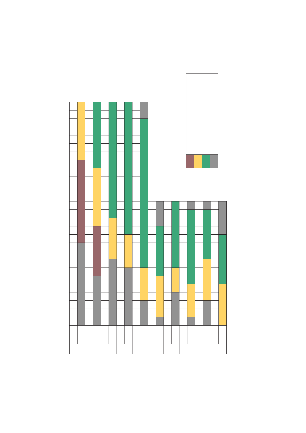
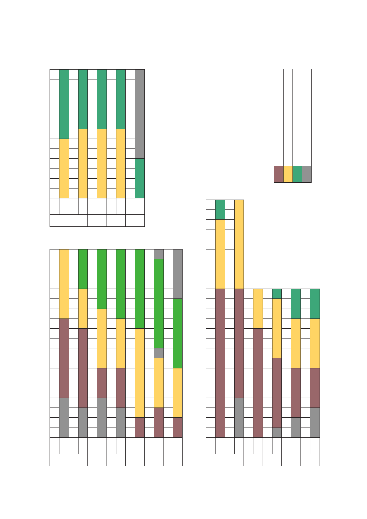
17.0 RANGE OF APPLICATION TABLES
TOOL ATM-2 ATM-2
CLASS A
NPS 4" 5" 6" 7" 8" 9" 10" 12" 13" 14" 15" 16" 17" 18" 19" 20" 21" 22" 23" 24" 29" 30" 33" 35" 36" 39" 42" 45" 48" 54" 60" 66" 72" 78" 84" 96" 108" 120"
NPS
TOOL ATM-2 ATM-4 ATM-9
CLASS D
TOOL ATM-2 ATM-4 ATM-9
CLASS E
NPS
TOOL ATM-2 ATM-4 ATM-9
CLASS F
NPS
TOOL ATM-2 ATM-4
CLASS H
NPS
TOOL ATM-2 ATM-4 ATM-9
CLASS J
NPS 1"
TOOL ATM-2 ATM-4 ATM-9
CLASS K
NPS 1"
NPS 1/2" 3/4" 1"
TOOL ATM-2 ATM-4 ATM-9
CLASS R
TOOL ATM-2 ATM-4 ATM-9
CLASS S
NPS 1/2" 3/4" 1"
TOOL ATM-2 ATM-4 ATM-9
CLASS T
NPS 1 13-16" 2 1-16" 2 9-16" 3 1-8" 4 1-16" 5 1-8" 7 1-16" 9" 11" 13 5-8" 16 3-4"
API6BX Weld Neck Flange Range of Application API6B Weld Neck Flange Range of Application
17.2 17.3
2K
TOOL ATM-2 ATM-4 ATM-9
CLASS
NPS 1 13-16" 2 1-16" 2 9-16" 3 1-8" 4 1-16" 5 1-8" 7 1-16" 9" 11" 13 5-8" 16 3-4"
3K
TOOL ATM-2 ATM-4 ATM-9
CLASS
NPS 1 13-16" 2 1-16" 2 9-16" 3 1-8" 4 1-16" 5 1-8" 7 1-16" 9" 11" 13 5-8" 16 3-4"
6K
TOOL ATM-4 ATM-9
CLASS
8
NPS 22" 26" 28" 30" 32" 34" 36" 38" 40" 42" 44" 46" 48"
NPS 22" 26" 28" 30" 32" 34" 36" 38" 40" 42" 44" 46" 48"
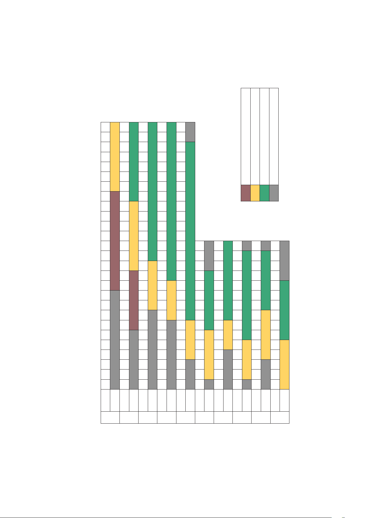
ASME B16.47 Flange Range of Application
ASME B16.47 Flange Range of Application
TOOL ATM-4 ATM-9
TOOL ATM-4 ATM-9
150
150
CLASS
CLASS
NPS 22" 26" 28" 30" 32" 34" 36" 38" 40" 42" 44" 46" 48"
NPS 22" 26" 28" 30" 32" 34" 36" 38" 40" 42" 44" 46" 48"
TOOL ATM-4 ATM-9
TOOL ATM-4 ATM-9
300
300
CLASS
CLASS
NPS 22" 26" 28" 30" 32" 34" 36" 38" 40" 42" 44" 46" 48"
NPS 22" 26" 28" 30" 32" 34" 36" 38" 40" 42" 44" 46" 48"
TOOL ATM-4 ATM-9
TOOL ATM-4 ATM-9
400
400
CLASS
CLASS
NPS 22" 26" 28" 30" 32" 34" 36" 38" 40" 42" 44" 46" 48"
NPS 22" 26" 28" 30" 32" 34" 36" 38" 40" 42" 44" 46" 48"
TOOL ATM-4 ATM-9
TOOL ATM-4 ATM-9
600
600
CLASS
CLASS
NPS 22" 26" 28" 30" 32" 34" 36" 38" 40" 42" 44" 46" 48"
NPS 22" 26" 28" 30" 32" 34" 36" 38" 40" 42" 44" 46" 48"
TOOL ATM-9
TOOL ATM-9
900
900
CLASS
CLASS
ATM-
ATM-
SUITABLE FOR ENERPAC ATM-2 TOOL
SUITABLE FOR ENERPAC ATM-2 TOOL
9
9
SUITABLE FOR ENERPAC ATM-4 TOOL
SUITABLE FOR ENERPAC ATM-4 TOOL
SUITABLE FOR ENERPAC ATM-9 TOOL
SUITABLE FOR ENERPAC ATM-9 TOOL
NOT SUITABLE FOR ANY ENERPAC ATM TOOL
NOT SUITABLE FOR ANY ENERPAC ATM TOOL
Note: Models ATM-2 and ATM-4 shown for reference purposes only.
Note: Models ATM-2 and ATM-4 shown for reference purposes only.
4" 5" 6" 8" 10" 12" 14" 16" 18" 20" 24"
4" 5" 6" 8" 10" 12" 14" 16" 18" 20" 24"
3
3
3"
3"
2
2
2"
2"
1
1
1
1
NPS 3/4" 1"
NPS 3/4" 1"
ASME B16.5 Flange Range of Application
ASME B16.5 Flange Range of Application
17.4 17.6
17.0 RANGE OF APPLICATION TABLES (Continued)
1/2"
1/2"
1/2"
1/2"
1/2"
1/2"
1/4"
1/4"
TOOL ATM-2 ATM-4
TOOL ATM-2 ATM-4
150
150
CLASS
CLASS
4" 5" 6" 8" 10" 12" 14" 16" 18" 20" 24"
4" 5" 6" 8" 10" 12" 14" 16" 18" 20" 24"
3
3
3"
3"
2
2
2"
2"
1
1
1
1
NPS 3/4" 1"
NPS 3/4" 1"
1/2"
1/2"
1/2"
1/2"
1/2"
1/2"
1/4"
1/4"
TOOL ATM-2 ATM-4 ATM-9
TOOL ATM-2 ATM-4 ATM-9
300
300
CLASS
CLASS
4" 5" 6" 8" 10" 12" 14" 16" 18" 20" 24"
4" 5" 6" 8" 10" 12" 14" 16" 18" 20" 24"
3
3
3"
3"
2
2
2"
2"
1
1
1
1
NPS 3/4" 1"
NPS 3/4" 1"
1/2"
1/2"
1/2"
1/2"
1/2"
1/2"
1/4"
1/4"
TOOL ATM-2 ATM-4 ATM-9
TOOL ATM-2 ATM-4 ATM-9
400
400
CLASS
CLASS
4" 5" 6" 8" 10" 12" 14" 16" 18" 20" 24"
4" 5" 6" 8" 10" 12" 14" 16" 18" 20" 24"
3
3
3"
3"
2
2
2"
2"
1
1
1
1
NPS 3/4" 1"
NPS 3/4" 1"
1/2"
1/2"
1/2"
1/2"
1/2"
1/2"
1/4"
1/4"
TOOL ATM-2 ATM-4 ATM-9
TOOL ATM-2 ATM-4 ATM-9
600
600
CLASS
CLASS
3" 4" 5" 6" 8" 10" 12" 14" 16" 18" 20" 24"
3" 4" 5" 6" 8" 10" 12" 14" 16" 18" 20" 24"
2
2
2"
2"
1
1
1
1
NPS 1/2" 3/4" 1"
NPS 1/2" 3/4" 1"
1/2"
1/2"
1/2"
1/2"
1/4"
1/4"
TOOL ATM-2 ATM-4 ATM-9
TOOL ATM-2 ATM-4 ATM-9
900
900
CLASS
CLASS
3" 4" 5" 6" 8" 10" 12" 14" 16" 18" 20" 24"
3" 4" 5" 6" 8" 10" 12" 14" 16" 18" 20" 24"
2
2
2"
2"
1
1
1
1
NPS 1/2" 3/4" 1"
NPS 1/2" 3/4" 1"
1/2"
1/2"
1/2"
1/2"
1/4"
1/4"
TOOL ATM-2 ATM-4 ATM-9
TOOL ATM-2 ATM-4 ATM-9
1500
1500
CLASS
CLASS
3" 4" 5" 6" 8" 10" 12" 14" 16" 18" 20" 24"
3" 4" 5" 6" 8" 10" 12" 14" 16" 18" 20" 24"
2
2
1/2"
1/2"
2"
2"
1
1
1/2"
1/2"
1
1
1/4"
1/4"
NPS 1/2" 3/4" 1"
NPS 1/2" 3/4" 1"
TOOL ATM-2 ATM-4 ATM-9
TOOL ATM-2 ATM-4 ATM-9
2500
2500
CLASS
CLASS
99
3" 4" 5" 6" 7" 8" 10" 12" 14" 16" 18" 20" 24" 28" 32" 36" 40"
3" 4" 5" 6" 7" 8" 10" 12" 14" 16" 18" 20" 24" 28" 32" 36" 40"
2
2
1/2"
1/2"
2"
2"
1
1
1/2"
1/2"
1
1
3" 4" 5" 6" 7" 8" 10" 12" 14" 16" 18" 20" 24" 28" 32" 36" 40" 48" 56 72" 80"
3" 4" 5" 6" 7" 8" 10" 12" 14" 16" 18" 20" 24" 28" 32" 36" 40" 48" 56 72" 80"
2
2
1/2"
1/2"
2"
2"
1
1
1/2"
1/2"
NPS
NPS
DIN Weld Neck Flange Range of Application
DIN Weld Neck Flange Range of Application
17.5
TOOL ATM-2 ATM-4 ATM-9
TOOL ATM-2 ATM-4 ATM-9
PN16
PN16
CLASS
CLASS
NPS 1/2" 3/4" 1"
NPS 1/2" 3/4" 1"
1/4"
1/4"
TOOL ATM-2 ATM-4
TOOL ATM-2 ATM-4
PN25
PN25
CLASS
CLASS
2
2
1
1
3" 4" 5" 6" 7" 8" 10" 12" 14" 16" 18" 20"
3" 4" 5" 6" 7" 8" 10" 12" 14" 16" 18" 20"
2"
2"
NPS
NPS
1/2"
1/2"
1/2"
1/2"
TOOL ATM-2 ATM-4
TOOL ATM-2 ATM-4
PN40
PN40
CLASS
CLASS
3" 4" 5" 6" 7" 8" 10" 12" 14" 16"
3" 4" 5" 6" 7" 8" 10" 12" 14" 16"
2
2
2"
2"
1
1
NPS 3/4" 1"
NPS 3/4" 1"
1/2"
1/2"
1/2"
1/2"
TOOL ATM-2 ATM-4
TOOL ATM-2 ATM-4
PN54
PN54
CLASS
CLASS
3" 4" 5" 6" 7" 8" 10" 12" 14"
3" 4" 5" 6" 7" 8" 10" 12" 14"
2
2
2"
2"
1
1
NPS 1/2" 3/4" 1"
NPS 1/2" 3/4" 1"
1/2"
1/2"
1/2"
1/2"
TOOL ATM-2 ATM-4 ATM-9
TOOL ATM-2 ATM-4 ATM-9
PN100
PN100
CLASS
CLASS
3" 4" 5" 6" 7" 8" 10" 12"
3" 4" 5" 6" 7" 8" 10" 12"
2
2
2"
2"
1
1
NPS 3/8" 1/2" 3/4" 1"
NPS 3/8" 1/2" 3/4" 1"
1/2"
1/2"
1/2"
1/2"
TOOL ATM-2 ATM-4 ATM-9
TOOL ATM-2 ATM-4 ATM-9
PN160
PN160
CLASS
CLASS
SUITABLE FOR ENERPAC ATM-2 TOOL
SUITABLE FOR ENERPAC ATM-2 TOOL
SUITABLE FOR ENERPAC ATM-4 TOOL
SUITABLE FOR ENERPAC ATM-4 TOOL
SUITABLE FOR ENERPAC ATM-9 TOOL
SUITABLE FOR ENERPAC ATM-9 TOOL
NOT SUITABLE FOR ANY ENERPAC ATM TOOL
NOT SUITABLE FOR ANY ENERPAC ATM TOOL
Note: Models ATM-2 and ATM-4 shown for reference purposes only.
Note: Models ATM-2 and ATM-4 shown for reference purposes only.
4" 5" 6" 8" 10" 12" 14" 16" 18" 20" 22" 24" 26" 28" 30" 32" 34" 36" 38" 40" 42" 44" 46" 48"
4" 5" 6" 8" 10" 12" 14" 16" 18" 20" 22" 24" 26" 28" 30" 32" 34" 36" 38" 40" 42" 44" 46" 48"
3
3
3"
3"
2
2
TOOL\NPS
TOOL\NPS
17.7
SPO Flange Range of Application
SPO Flange Range of Application
1/2"
1/2"
1/2"
1/2"
TOOL ATM-2 ATM-4
TOOL ATM-2 ATM-4
150
150
CLASS
CLASS
4" 5" 6" 8" 10" 12" 14" 16" 18" 20" 22" 24" 26" 28" 30" 32" 34" 36" 38" 40" 42" 44" 46" 48"
4" 5" 6" 8" 10" 12" 14" 16" 18" 20" 22" 24" 26" 28" 30" 32" 34" 36" 38" 40" 42" 44" 46" 48"
3
3
1/2"
1/2"
3"
3"
2
2
1/2"
1/2"
TOOL\NPS
TOOL\NPS
300
300
TOOL ATM-2 ATM-4 ATM-9
TOOL ATM-2 ATM-4 ATM-9
CLASS
CLASS
4" 5" 6" 8" 10" 12" 14" 16" 18" 20" 22" 24" 26" 28" 30" 32" 34" 36" 38" 40" 42" 44" 46" 48"
4" 5" 6" 8" 10" 12" 14" 16" 18" 20" 22" 24" 26" 28" 30" 32" 34" 36" 38" 40" 42" 44" 46" 48"
3
3
1/2"
1/2"
3"
3"
2
2
1/2"
1/2"
TOOL\NPS
TOOL\NPS
600
600
TOOL ATM-4 ATM-9
TOOL ATM-4 ATM-9
CLASS
CLASS
4" 5" 6" 8" 10" 12" 14" 16" 18" 20" 22" 24" 26" 28" 30" 32" 34" 36" 38" 40" 42" 44" 46" 48"
4" 5" 6" 8" 10" 12" 14" 16" 18" 20" 22" 24" 26" 28" 30" 32" 34" 36" 38" 40" 42" 44" 46" 48"
3
3
1/2"
1/2"
3"
3"
2
2
1/2"
1/2"
TOOL\NPS
TOOL\NPS
900
900
TOOL ATM-4 ATM-9
TOOL ATM-4 ATM-9
CLASS
CLASS
4" 5" 6" 8" 10" 12" 14" 16" 18" 20" 22" 24" 26" 28" 30" 32" 34" 36" 38" 40" 42" 44" 46" 48"
4" 5" 6" 8" 10" 12" 14" 16" 18" 20" 22" 24" 26" 28" 30" 32" 34" 36" 38" 40" 42" 44" 46" 48"
3
3
1/2"
1/2"
3"
3"
2
2
1/2"
1/2"
TOOL\NPS
TOOL\NPS
TOOL ATM-4 ATM-9
TOOL ATM-4 ATM-9
1500
1500
CLASS
CLASS
17.0 RANGE OF APPLICATION TABLES (Continued)
1010
4" 5" 6" 8" 10" 12" 14" 16" 18" 20" 22" 24"
4" 5" 6" 8" 10" 12" 14" 16" 18" 20" 22" 24"
3
3
1/2"
1/2"
3"
3"
2
2
1/2"
1/2"
TOOL\NPS
TOOL\NPS
TOOL ATM-4 ATM-9
TOOL ATM-4 ATM-9
2500
2500
CLASS
CLASS
4" 5" 6" 8" 10" 12" 14" 16" 18" 20" 22" 24"
4" 5" 6" 8" 10" 12" 14" 16" 18" 20" 22" 24"
3
3
1/2"
1/2"
3"
3"
2
2
1/2"
1/2"
TOOL\NPS
TOOL\NPS
TOOL ATM-4 ATM-9
TOOL ATM-4 ATM-9
5000
5000
CLASS
CLASS
4" 5" 6" 8" 10" 12" 14" 16" 18" 20" 22" 24"
4" 5" 6" 8" 10" 12" 14" 16" 18" 20" 22" 24"
3
3
1/2"
1/2"
3"
3"
2
2
1/2"
1/2"
TOOL\NPS
TOOL\NPS
7500
7500
TOOL ATM-4 ATM-9
TOOL ATM-4 ATM-9
CLASS
CLASS
4" 5" 6" 8" 10" 12" 14" 16" 18" 20" 22" 24"
4" 5" 6" 8" 10" 12" 14" 16" 18" 20" 22" 24"
3
3
1/2"
1/2"
3"
3"
2
2
1/2"
1/2"
TOOL\NPS
TOOL\NPS
TOOL ATM-4 ATM-9
TOOL ATM-4 ATM-9
10000
10000
CLASS
CLASS
4" 5" 6" 8" 10" 12" 14" 16" 18" 20" 22" 24"
4" 5" 6" 8" 10" 12" 14" 16" 18" 20" 22" 24"
3
3
1/2"
1/2"
3"
3"
2
2
1/2"
1/2"
TOOL\NPS
TOOL\NPS
TOOL ATM-4 ATM-9
TOOL ATM-4 ATM-9
15000
15000
CLASS
CLASS
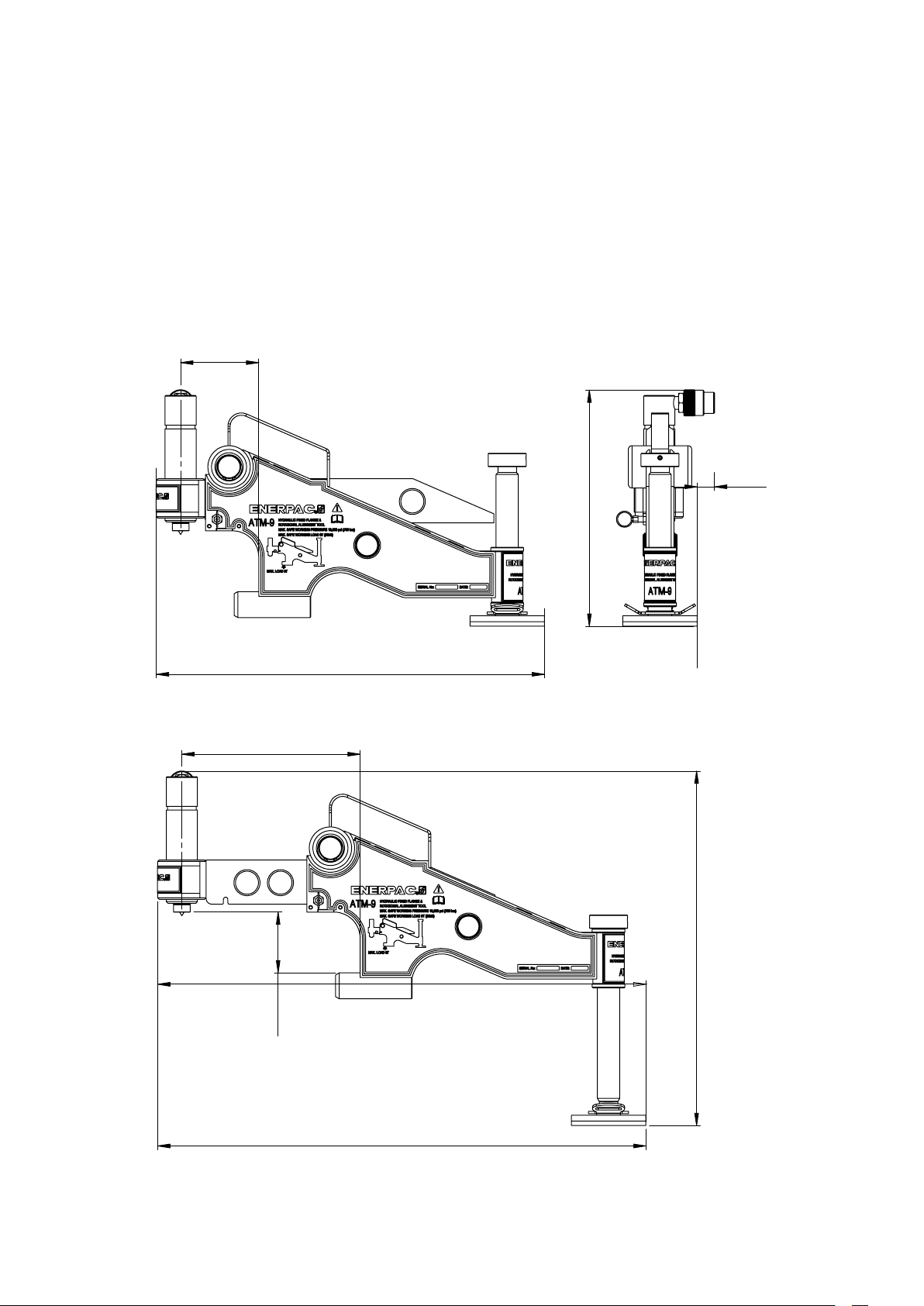
18.0 WEIGHTS AND DIMENSIONS
Note: Weights shown are approximate.
WEIGHTS
Tool with hydraulic cylinder and strap ............................................33.3 lbs [15,1 kg]
Hand pump ..................................................................5.3 lbs [2,4 kg]
Hydraulic hose ...............................................................2.2 lbs [1,0 kg]
Carrying case ...............................................................19.6 lbs [8,9 kg]
Gross weight of all items listed above ............................................60.4 lbs [27,4 kg]
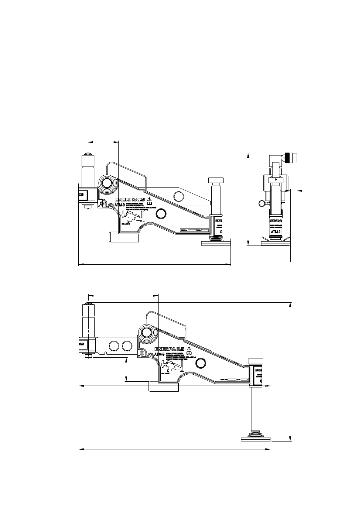
DIMENSIONS
4.13"
[105 mm]
MINIMUM EXTENSION
0.94"
[24 mm]
10.51" [267 mm]
9.44" [240 mm]
3.22"
[82 mm]
20.51" [521 mm]
MAXIMUM EXTENSION
18.54" [471 mm]
25.82" [656 mm]
11

Notes:
.
.
.
.
.
.
.
.
.
.
.
12

L4065 Rév. B 02/14
Manuel d'instructions
Outil hydraulique d'alignement
de bride
Modèle ATM-9
Paragraphe page
1.0 Instructions pour la réception .......... 14
2.0 Sécurité ........................... 14
3.0 Description du produit ............... 15
4.0 Informations de sécurité .............. 15
5.0 Liste équipement. . . . . . . . . . . . . . . . . . . . 15
6.0 Identification de désalignement ........ 15
7.0 Installation et utilisation. . . . . . . . . . . . . . . 16
8.0 Torsion ou décalage rotationnel ........ 17
9.0 Démontage de l'ATM-9 ............... 18
10.0 Inspection et examen ............... 18
11.0 Stockage ........................ 18
12.0 Lubrification et entretien ............ 18
13.0 Dépannage ....................... 20
14.0 Élimination de poche d'air ........... 20
15.0 Extension minimale / maximale ....... 20
16.0 Applications ...................... 20
17.0 Tableaux des applications ......... 21-23
18.0 Tailles et poids ................... 24
1313
1.0 INSTRUCTIONS POUR LA RÉCEPTION
A la réception du matériel, veuillez contrôler qu’aucun
composant n’a été endommagé par le transport. Ces
dommages ne sont pas couverts par la garantie. En cas
de dommages liés au transport, veuillez directement en
informer le transporteur. Celui-ci est tenu de prendre en
charge tous les frais de réparation et de remplacement
résultant des dommages occasionnés lors du transport.
sécurité d’abord
Veuillez lire attentivement toutes les instructions et
avertissements. Suivez toutes les recommandations pour
la sécurité afin d’éviter les blessures ou la détérioration
d’objets pendant l’utilisation du système. Enerpac ne
peut être tenu pour responsable des dommages et
blessures qui résultent d’une utilisation dangereuse, d’un
manque de maintenance ou d’un maniement incorrect du
produit et/ou du système. En cas de doute concernant
les précautions et les mesures de sécurité, n’hésitez
pas à contacter Enerpac. Utilisez exclusivement l’huile
hydraulique d’Enerpac afin de conserver votre garantie.
La mention PRECAUTION indique les procédures de
mise en fonctionnement et d’entretien à suivre ainsi que
les opérations à effectuer afin d’éviter tout dommage ou
toute entrave au fonctionnement de l’équipement ou d’un
autre matériel.
La mention AVERTISSEMENT signale un danger potentiel.
Veuillez suivre les procédures adéquates ou effectuer les
opérations nécessaires afin d’éviter tout dommage corporel.
2.0 SÉCURITÉ
Ne pas tenir compte des mentions
PRECAUTION et AVERTISSEMENT
ci-dessous peut mener à la
détérioration de l’équipement et être source de blessures.
IMPORTANT : L’opérateur doit être âgé d’au
moins dix-huit ans. Il doit avoir lu et compris
toutes les instructions, les données pour la
sécurité, les mentions PRECAUTION et AVERTISSEMENT
avant de commencer à travailler avec un équipement
Enerpac. L’opérateur est responsable des conséquences
que son travail pourrait avoir pour d’autres personnes.
AVERTISSEMENT : Pour éviter les blessures et
la détérioration de l’équipement, assurez-vous
que tous les composants hydrauliques peuvent
supporter la pression maximale de 700 bars [10.000 psi].
IMPORTANT : Minimisez les risques de
surcharge. Utilisez des manomètres
hydrauliques dans chaque circuit hydraulique,
ils indiquent la charge et rendent le travail plus sûr. Ils
permettent de voir ce qui se passe dans le système.
sources externes comme la chaleur excessive, le feu, les
pièces mobiles d’une machine, les bords pointus et les
produits chimiques corrosifs.
et supportent les charges préconisées.
défaut de l’outil ou de la pièce de travail.
sérieuses blessures. Si de l’huile a été injectée sous la
peau, consultez immédiatement un médecin.
déplacer en sécurité.
hydrauliques Enerpac disposent aussi bien d’une unité
d’entraînement carrée que d’une unité hexagonale pour
desserrer ou resserrer les boulons et les écrous. Enerpac
fournit des casses-écrous dans le cas où un écrou ne
pourrait pas être démonté.
AVERTISSEMENT : Ne surchargez pas
l’équipement. La surcharge entraîne des
pannes et peut provoquer des blessures.
PRÉCAUTION : Tous les composants du
système doivent être protégés contre tout
dommage pouvant être occasionné par des
PRÉCAUTION : Pour les flexibles, évitez les
rayons de courbures trop serrés et les pliures,
causes de pertes de pression. Les courbures et
les pliures accélèrent la défaillance des flexibles.
AVERTISSEMENT : Remplacez immédiatement
tous les éléments usés ou endommagés par
des pièces d’origine Enerpac. Les pièces
d’origine Enerpac sont parfaitement conformes
AVERTISSEMENT : Portez toujours des
lunettes de sécurité. L’opérateur doit toujours
prendre des précautions contre les risques de
dommages corporels encourus en cas de
DANGER : Ne manipulez pas de flexibles sous
pression. En s’échappant, l’huile sous pression
peut traverser la peau et provoquer de
AVERTISSEMENT : Ne mettez jamais sous
pression des raccords désaccouplés. N’utilisez
que de l’équipement hydraulique dans un
système sous pression.
IMPORTANT : NE déplacez PAS un
équipement hydraulique en tirant sur les
flexibles ou les raccords. Utilisez la poignée de
transport ou un autre moyen permettant de le
Nous vous recommandons d’utiliser les liquides
ou les vaporisateurs spécialement conçus pour
le desserrage. Les clés dynamométriques
1414
3.0 DESCRIPTION DU PRODUIT
4.0 INFORMATIONS DE SÉCURITÉ
L'outil d'alignement ATM-9 est conçu pour une utilisation
dans des procédures de maintenance et d'installation
courantes. Il permet le réalignement des brides mal
alignées jusqu'à une capacité physique de 9 Tonnes
[90 kN]. Par exemple, il peut être utilisé pour aider au
IMPORTANT : Dans toutes les configurations, les
consignes de sécurité sur site doivent être respectées.
La sécurité de l'utilisateur et de tout assistant est d'une
importance capitale ainsi que la sécurité de tiers, incluant
tout passant.
remplacement de bagues et d'autres types de joints.
Ces instructions visent uniquement l'utilisation en toute
L´ATM-9 est un outil à commande hydraulique actionné
par un vérin hydraulique et une pompe à main. La pression
de travail maximale est de 700 bars [10 000 psi].
sécurité de l'ATM-9 lors d'une intervention habituelle
d'entretien et d'installation. Tous les autres aspects de la
sécurité doivent être vérifiés par le superviseur des travaux.
L'utilisation de ce mode d'emploi favorise une utilisation
en toute sécurité et une durée d'utilisation maximale de
l'outil. Il est impératif de lire toutes les sections de ce
mode d'emploi avant d'utiliser l'outil.
3.1 Caractéristiques et composants principaux
Fig. 1
hydraulique
Vérin
Outil
ATM-9
Jambe support
produire si vous retirez les boulons alors que l'outil est
installé, et la force en résultant dépasse la charge
admissible sans danger par l'outil.
5.0 LISTE ÉQUIPEMENT
Le coffret comprend les accessoires suivants :
• Outil d'alignement ATM-9 avec vérin hydraulique.
Flexible
hydraulique
• Flexible hydraulique, 1,8 m [6 pieds] de long.
• Pompe à main hydraulique P-142.
• Raccords de 3/8 pouce NPTF sur flexible, vérin et
pompe.
• Roue à cliquet et sangle.
• Manuel d'instructions.
• Coffret de rangement.
PRÉCAUTION : Il est interdit de fixer l'ATM-9
aux buses d'un récipient sous pression.
AVERTISSEMENT: Attendez toujours d'avoir
dévissé et retiré les boulons de bride avant de
fixer l'ATM-9 à un joint. Une surcharge peut se
Sangle
Pompe hydraulique
P-142
3.2 Données techniques
Description outil : Force d'alignement :
Outil hydraulique rectifiant
la torsion et le décalage
rotationnel des brides.
Remarque : Voir la section 18.0 pour les poids et les
dimensions.
9.0 T [90 kN]
à 700 bars [10 000 psi] de
pression hydraulique.
Remarque : Tous les composants hydrauliques sont
réglés pour un fonctionnement à 700 bars [10 000 psi].
6.0 PROCÉDURE D'IDENTIFICATION
DÉSALIGNEMENT
• Attendre d'avoir effectué la procédure d'identification
de désalignement pour fixer l'ATM-9 à une bride. Voir
l'avertissement à la section 4.0.
• Dévisser et retirer un boulon sur deux. Poursuivre
cette procédure. Il se peut que le mauvais alignement
apparaisse uniquement lorsqu'il ne reste que quelques
boulons. À ce point-là, le sens de tout désalignement
doit être évident.
• Dès qu'il aura été fixé, l'ATM-9 pousse directement
contre le désalignement, réalignant ainsi le joint.
1515
Exemple: Désalignement dans plusieurs directions
Fig. 4
Une fois démonté, un joint à bride peut sortir de son
alignement à n'importe quel endroit et dans n'importe
quel sens.
Bouton de
Réglage
Voir fig. 2. L'ATM-9 doit être fixé au point de désalignement
maximal par ex. A ou B. Chaque exemple indique le point
de fixation de l'ATM-9.
Fig. 2
Remarque : Pendant le réglage, l'outil doit être maintenu
de niveau dans le passage du boulon. L'outil doit à tout
moment rester parallèle au tuyau.
3. Retirer la broche de blocage et allonger le bras à la
7.0 INSTALLATION ET UTILISATION
1. Déterminer le point de désalignement maximal. (voir
fig.3). Les points maximum se trouvent en haut ou en
bas du joint, comme indiqué par les flèches.
Fig. 3
Point de
désalignement
maximal
4. Fixer le crochet de la sangle en passant par l'une des
Crochet de
levage
Jambe
Support
distance désirée (voir fig. 5). Faire tourner le vérin de
gauche à droite jusqu'à ce qu'il vienne se poser à la
surface de la bride opposée. À ce stade, s'assurer que
l'outil est bien de niveau et que l'extrémité du vérin
touche pleinement la surface de la bride la plus haute.
fentes de la boucle (au-dessus du pied de la jambe
support). Faire passer le crochet de la roue à cliquet
dans l'autre fente, du côté opposé de la boucle. Passer
l'extrémité de la sangle par la roue à cliquet et serrer.
(voir fig.6).
Point de
désalignement
maximal
2. Guider le crochet de levage de l'outil dans le passage du
boulon au point de désalignement maximal. Abaisser
ensuite la jambe support sur le tuyau en tournant le
bouton de réglage de gauche à droite (voir fig.4).
Fig. 5
Vérin
hydraulique
Bras
Broche de
blocage bras
16
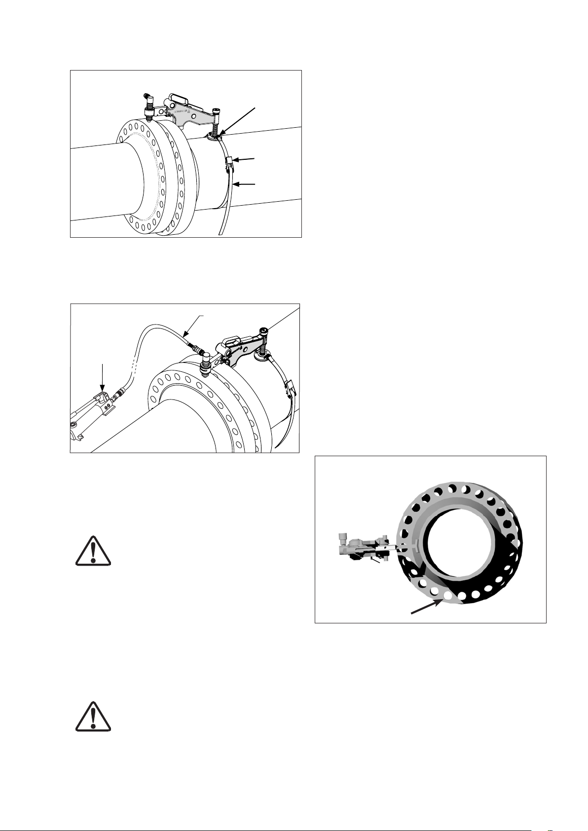
Fig. 6
Boucle
Roue à
cliquet
Sangle
5. Raccorder la pompe hydraulique P-142 au flexible
hydraulique et le flexible au vérin hydraulique. Actionner
la poignée de la pompe jusqu'à ce que le joint s'aligne.
(voir fig.7).
Fig. 7
Pompe
hydraulique
à main
Flexible
hydraulique
7. Après avoir retiré l'outil de la bride, poser et serrer le
dernier boulon de bride dans le passage restant.
8.0 TORSION OU DÉCALAGE ROTATIONNEL
Il s'agit d'un problème courant tant sur les conduites en
mer que sur terre (voir fig. 8). Assez souvent, malgré le fait
que les brides sont alignées, l'opérateur ne parvient pas à
introduire un boulon dans le passage correspondant, à la
circonférence du joint. L'ATM-9, avec sa capacité de 90
kN [9 tonnes], est en mesure de manipuler les brides dans
plusieurs directions.
La procédure de mise en place est la même que
précédemment, à l'exception d'une seule situation.
L'ATM-9 peut être fixé au point le plus accessible sur la
circonférence du joint, car le désalignement se produit
selon le même degré au niveau de tous les passages de
boulon.
8.1 Les procédures d'intervention recommandées
sont les suivantes :
1. Choisir le point le plus pratique ou le plus accessible
sur la circonférence du joint et fixer l'outil à cet endroit.
(Suivre les étapes 1 à 5 à la section 7.0).
2. Dans l'éventualité où les deux brides sont alignées mais
Remarque : Le vérin hydraulique de l'ATM-9 est réglé
Fig. 8
à une pression de fonctionnement de 700 bars [10 000
psi]. La pompe hydraulique P-142 contient une valve de
surpression intégrée qui s'ouvre à environ 724 bars [10
500 psi].
AVERTISSEMENT: Si, pour n'importe quelle
raison, une pompe autre que la P-142 est
utilisée, s'assurer que le réglage de la valve de
surpression intégrée n'est pas supérieur à 724 bars [10
500 psi]. Installer un manomètre dans le circuit pour
surveiller la pression du système.
6. Lorsque l'alignement est terminé, vous pouvez
introduire et serrer les boulons de bride. Après avoir
remplacé tous les boulons dans tous les passages (à
3. Introduire le boulon dans le passage au point A, puis
l'exception de celui où se trouve le crochet de levage
de l'outil), retirer l'outil en suivant les étapes 1 à 5, en
sens inverse.
4. Ensuite, l'ATM-9 peut être fixé à un autre point sur la
PRÉCAUTION : Ouvrir la valve de surpression
et s'assurer du relâchement de toute la pression
hydraulique avant de déconnecter n'importe
quel flexible ou raccord.
5. Vous pouvez retirer l'ATM-9 dès que les boulons
présentent un décalage rotationnel, l'ATM-9 est utilisé
pour pousser les brides au-delà de l'alignement jusqu'à
ce qu'une paire de passages devienne parallèle (voir
point A à la fig. 8).
A
relâchez l'ATM-9. La charge sera transférée sur le
boulon.
circonférence du joint (voir fig. 9) en poussant contre
le boulon tout juste mis en place. Avancer le vérin
hydraulique jusqu'à ce qu'un autre passage ou tous les
passages soient parallèles (voir fig. 10).
1717
restants sont mis en place.
Fig. 9
les éléments pour s'assurer qu'ils sont aptes au service.
• Tout élément manquant ou endommagé doit être
remplacé le plus rapidement possible avant d'utiliser à
nouveau l'outil.
• Graisser régulièrement toutes les pièces mobiles. Voir
la section 12.0 Lubrification et entretien.
• Remettre le bouchon ou capuchon sur tous les raccords
hydrauliques afin d'éviter la pénétration de saleté.
S'assurer que le capuchon du purgeur d'air de la
pompe se trouve en position fermée.
• S'assurer que les rouleaux et broches ne présentent
pas d'abrasif.
• Remettre tous les éléments non utilisés dans le coffret
de rangement.
A
11.0 STOCKAGE
• Mettre un capuchon ou un bouchon sur tous les
Fig. 10
• Lubrifier les surfaces usinées avec de la graisse.
• L'ATM-9 doit être stocké au sec et à l'abri de la chaleur.
12.0 LUBRIFICATION ET ENTRETIEN
Utiliser de la graisse Mobilgrease XHP ™ 222 Special
ou toute autre graisse équivalente de bonne qualité pour
utilisation intensive.
S'assurer que le bras de l'outil est dépourvu d'abrasif, que
les rouleaux tournent librement et qu'ils sont bien lubrifiés
(voir fig. 13). Cela améliore les performances de l'outil et
contribue à prolonger sa durée de vie.
Veuillez noter que dans certaines situations, il se peut que
l'opérateur soit dans l’obligation de chercher le
désalignement tout autour de la circonférence du joint et
Nettoyer, inspecter et lubrifier l'ATM-9 conformément aux
étapes suivantes :
fixer l'ATM-9 à plusieurs endroits pour rectifier le
désalignement. À chaque occasion, il convient de suivre
ÉTAPE 1: Poser l´outil à plat sur l'établi.
les procédures décrites aux étapes 1 à 7 à la section 7.0.
ÉTAPE 2: Retirer les goupilles élastiques à l'avant du
9.0 DÉMONTAGE DE L'ATM-9
raccords hydrauliques ouverts.
corps principal (voir fig. 11)
• Lorsque l'alignement est atteint, tous les travaux sur le
ÉTAPE 3: Extraire la broche de blocage du bras en tirant
joint terminés, et le reboulonnage terminé (à l'exception
du passage du boulon dans lequel se trouve l'ATM-9),
l'outil peut être retiré du joint en suivant en sens inverse
les étapes 1 à 5 à la section 7.0.
ÉTAPE 4: Retirer les anneaux élastiques avec une pince
• Il convient de faire attention à ne pas laisser tomber de
pièces lorsque vous les retirez des joints alignés. Vous
éviterez ainsi de blesser le personnel.
ÉTAPE 5: Faire sortir en glissant les axes de rouleau pour
Remarque : Voir la fiche des pièces de rechange de
l'ATM-9 pour la liste complète des pièces et les schémas
de montage.
ÉTAPE 6: Inspecter les axes de rouleau, les rouleaux et
10.0 INSPECTION ET EXAMEN
• Une fois la tâche terminée et avant de remettre l'ATM-9
en service, vérifier que l'outil est complet et examiner
1818
dessus. Retirer le bras du corps principal en le
faisant glisser vers l'avant (voir fig. 12).
(voir fig. 13).
pouvoir retirer les rouleaux et les paliers afin de
les examiner. (voir fig.13).
les paliers pour y détecter d'éventuels dégâts.
En l'absence de dégâts, ces pièces peuvent
être nettoyées, graissées et remontées (étapes
1 à 5 en sens inverse).
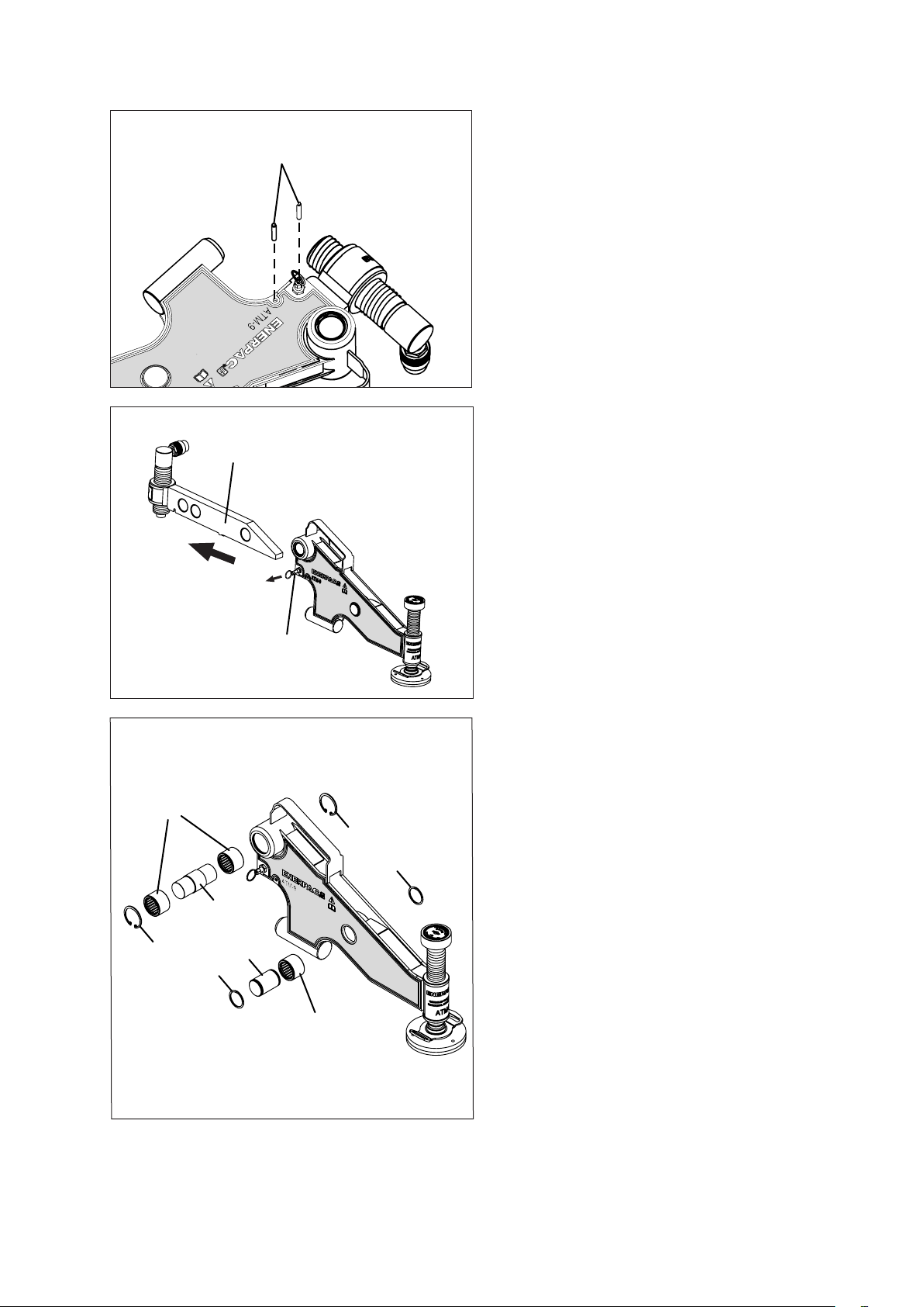
Fig. 11
13.0 DÉPANNAGE
Fig. 12
Goupilles élastiques
Bras
Broche de blocage bras
Problème 1 :
Le vérin hydraulique coulisse sur la circonférence de la
bride opposée alors que l'ATM-9 aligne le joint.
Cause :
Abrasif ou saleté sur le bras, les rouleaux ou les paliers, le
bras est en extension complète.
Solution :
A. S'assurer que les rouleaux tournent librement et que
rien (par ex. saleté ou abrasif) ne les gêne sur la surface
du bras.
B. Vérifier que le bras n'est pas en extension complète lors
de l'alignement du joint.
C. S'assurer qu'il reste assez d'extension pour permettre
l'extension de l'ATM-9 lors de l'alignement du joint.
Problème 2 :
L'ATM-9 est fixé et semble fonctionner correctement, mais
le joint ne s'aligne pas.
Cause :
A. Il peut y avoir de l'air dans le système hydraulique et ce
dernier réduit la force exercée sur les brides.
B. Quelque chose peut gêner le joint à un point proche
des brides. Il se peut que le joint nécessite une pression
supérieure à 9 tonnes [90 kN] pour s'aligner.
Fig. 13
1
3
2
2
1. Rouleaux et paliers
2. Anneaux élastiques
3. Axes de rouleaux
Solution :
A. Voir les instructions d'élimination de poche d'air à la
section 14.
B. Vérifier la zone autour du joint pour voir s'il est gêné par
un obstacle.
C. S'il faut une force supérieure à la capacité de 9 tonnes
[90 kN] de l'outil, choisissez une autre méthode pour
aligner le joint.
2
2
14.0 ÉLIMINATION DE POCHE D'AIR
Procéder comme suit pour éliminer l'air :
1. Retirer le capuchon du purgeur d'air de la pompe
hydraulique et s'assurer que le niveau d'huile hydraulique
est suffisant pour faire avancer le vérin.
3
2. Remettre le capuchon du purgeur d'air en place mais
sans le serrer. Le capuchon doit rester déserré (en
1
position de purge) afin de permettre à l'air d'entrer dans
la pompe et d'en sortir pendant son utilisation. Serrer
entièrement le capuchon uniquement lorsque vous
remettez l'outil dans son coffret après utilisation.
3. Alors que le capuchon du purgeur d'air est déserré,
raccorder la pompe à l'outil à l'aide du flexible
hydraulique fourni dans le coffret de rangement.
1919
4. Déposer l'outil sur une surface plane, maintenir la pompe
hydraulique au-dessus de l'outil, fermer la soupape de
décharge sur la pompe et amorcer la pompe pour
faire avancer entièrement le vérin hydraulique jusqu'à
atteindre une légère pression.
5. Alors que la pompe hydraulique est maintenue
au-dessus de l'outil, ouvrir la soupape de décharge
pour permettre au vérin de se rétracter entièrement.
Alors que le vérin se rétracte, tout air dans le système
est chassé vers la pompe et évacué par le capuchon du
purgeur d'air.
6. Répéter la procédure ci-dessus trois ou quatre fois pour
s'assurer que tout l'air est chassé et que l'outil atteint sa
pleine pression de fonctionnement.
15.0 EXTENSION MINIMALE / MAXIMALE
Se reporter à la section 18.0, Tailles et poids, pour toute
information sur l'extension minimale et maximale.
16.0 APPLICATIONS
Deux dimensions de base, A et B, déterminent si l'ATM-9
peut être utilisé pour aligner le joint. Si le joint de bride à
aligner se trouve entre 93 mm [3,66 pouces] et 228 mm [9
pouces] comme illustré par (A), et présente un passage de
boulon d'au moins 31,5 mm [1,24 pouces] (B), alors il est
possible de fixer l'ATM-9 et d'obtenir un alignement (voir
fig. 14).
Voir les tableaux à la section 17 : par type de bride, classe
et diamètre.
Fig 14 - Tailles min. & max. de bride (visuel)
La tête du vérin hydraulique
doit reposer entièrement sur
la circonférence de la bride
à pousser.
Taille min. de passage
de boulon
31,5 mm [1,24 pouces]
B
Distance min. 93 mm [3,66 pouces]
Distance max. 228 mm [9 pouces]
A
Passer le crochet
dans ce passage
de boulon
20
ATM-4 ATM-4
ATM-2
CONVIENT À L'OUTIL ENERPAC ATM-2
CONVIENT À L'OUTIL ENERPAC ATM-4
CONVIENT À L'OUTIL ENERPAC ATM-9
NE CONVIENT À AUCUN OUTIL ENERPAC ATM
Remarque : Les modèles ATM-2 et ATM-4 sont montrés
uniquement à titre de référence.
la bride
3K
Outil ATM-2 ATM-4 ATM-9
Catégorie
2 1-16" 2 9-16" 3 1-8" 4 1-16" 5 1-8" 7 1-16" 9" 11" 13 5-8" 16 3-4" 21 1-4"
Diamètre
intérieur de
1 13-16" 2 1-16" 2 9-16" 3 1-8" 4 1-16" 5 1-8" 7 1-16" 9" 11" 13 5-8" 16 3-4"
la bride
6K
Outil ATM-2 ATM-4 ATM-9
Catégorie
2 1-16" 2 9-16" 3 1-8" 4 1-16" 5 1-8" 7 1-16" 9" 11" 13 5-8" 16 3-4" 21 1-4"
Diamètre
intérieur de
5" 6" 7" 8" 9" 10" 11" 12" 13" 14" 15" 16"
4
4"
3
4" 5" 6" 7" 8" 9" 10" 12" 13" 14" 15" 16" 17" 18" 19" 20"
4" 5" 6" 7" 8" 9" 10" 12" 13" 14" 15" 16" 17" 18" 19" 20" 21" 22" 23" 24" 27" 29" 30" 33" 35" 36" 39" 42" 45" 48"
3
3"
2
2"
4" 5" 6" 7" 8" 9" 10" 12" 13" 14" 15" 16" 17" 18" 19" 20" 21" 22" 23" 24" 29" 30" 33" 35" 36" 39" 42" 45" 48" 54" 60" 66" 72" 78" 84" 96" 108" 120"
1
1
4" 5" 6" 7" 8" 9" 10" 12" 13" 14" 15" 16" 17" 18" 19" 20" 21" 22" 23" 24" 26" 27" 29" 30" 33" 35" 36" 39" 42" 45" 48" 54" 60" 66" 72"
3
1/2"
1/2"
1/2"
1/2"
1/4"
4" 5" 6" 7" 8" 9" 10" 12" 13" 14" 15" 16" 17" 18" 19" 20" 21" 22" 23" 24" 27" 29" 30" 33" 35" 36" 39" 42" 45" 48"
3
3"
2
2"
1
1
1/2"
1/2"
1/2"
1/4"
4" 5" 6" 7" 8" 9" 10" 12" 13" 14" 15" 16" 17" 18" 19" 20" 21" 22" 23" 24"
3
1/2"
3
3"
2
1/2"
2
2"
1
1
1/2"
1/4"
1
1
4" 5" 6" 7" 8" 9" 10" 12" 13" 14" 15" 16" 17" 18" 19" 20" 21" 22" 23" 24"
3"
2"
1/2"
1/2"
1/2"
1/4"
3
3"
2
2"
1
1
1"
1/2"
1/2"
1/2"
1/4"
4" 5" 6" 7" 8" 9" 10" 12" 13" 14" 15" 16" 17" 18" 19" 20"
3
3"
2
2"
1
1
1"
1/2"
1/2"
1/2"
1/4"
3"
2
2"
1
1
1/2" 3/4" 1"
1/2"
1/2"
1/2"
1/2"
1/4"
5" 6" 7" 8" 9" 10" 11" 12" 13"
4
1/2"
4"
3
1/2"
3"
2
1/2"
2"
1
1/2"
1
1/4"
TM-2 ATM-4 ATM-9
1/2" 3/4" 1"
1 13-16" 2 1-16" 2 9-16" 3 1-8" 4 1-16" 5 1-8" 7 1-16" 9" 11" 13 5-8" 16 3-4"
la bride
2K
Outil ATM-2 ATM-4 ATM-9
Catégorie
2 1-16" 2 9-16" 3 1-8" 4 1-16" 5 1-8" 7 1-16" 9" 11" 13 5-8" 16 3-4" 21 1-4"
Diamètre
intérieur de
1 13-16" 2 1-16" 2 9-16" 3 1-8" 4 1-16" 5 1-8" 7 1-16" 9" 11" 13 5-8" 16 3-4"
Outil ATM-2 ATM-2
la bride
Diamètre
intérieur de
A
Applications de brides BS10
17.1
17.0 TABLEAU DES APPLICATIONS
Outil ATM-2 ATM-4 ATM-9
la bride
Diamètre
intérieur de
D
Catégorie
Catégorie
Outil ATM-2 ATM-4 ATM-9
la bride
Diamètre
intérieur de
E
Catégorie
Outil ATM-2 ATM-4 ATM-9
la bride
Diamètre
Diamètre
intérieur de
intérieur de
F
Catégorie
la bride
H
Outil ATM-2 ATM-4
Catégorie
Outil ATM-2 ATM-4 ATM-9
la bride
Diamètre
intérieur de
J
Catégorie
Outil ATM-2 ATM-4 ATM-9
la bride
Diamètre
intérieur de
K
Catégorie
Outil ATM-2 ATM-4 ATM-9
la bride
Diamètre
intérieur de
R
Catégorie
Outil ATM-2 ATM-4 ATM-9
la bride
Diamètre
intérieur de
S
Catégorie
Outil A
la bride
Diamètre
intérieur de
T
Catégorie
17.2 17.3
Outil ATM-2 ATM-4 ATM-9
la bride
Diamètre
intérieur de
2K
Applications de brides à collerette API6BX Applications de brides à collerette API6B
Outil ATM-2 ATM-4 ATM-9
la bride
Diamètre
intérieur de
3K
Catégorie
Outil ATM-4 ATM-9
la bride
Diamètre
intérieur de
6K
Catégorie
Catégorie
21
CONVIENT À L'OUTIL ENERPAC ATM-2
CONVIENT À L'OUTIL ENERPAC ATM-4
CONVIENT À L'OUTIL ENERPAC ATM-9
NE CONVIENT À AUCUN OUTIL ENERPAC ATM
Remarque : Les modèles ATM-2 et ATM-4 sont montrés
uniquement à titre de référence.
22" 26" 28" 30" 32" 34" 36" 38" 40" 42" 44" 46" 48"
Diamètre
intérieur de
Applications de brides ASME B16.47
4" 5" 6" 8" 10" 12" 14" 16" 18" 20" 24"
3
3"
2
2"
1
1
3/4" 1"
la bride
1/2"
1/2"
1/2"
1/4"
150
Outil ATM-4 ATM-9
Catégorie
22" 26" 28" 30" 32" 34" 36" 38" 40" 42" 44" 46" 48"
22" 26" 28" 30" 32" 34" 36" 38" 40" 42" 44" 46" 48"
Outil ATM-4 ATM-9
la bride
Diamètre
Diamètre
intérieur de
3
2
1
1
4" 5" 6" 8" 10" 12" 14" 16" 18" 20" 24"
3"
2"
3/4" 1"
1/2"
1/2"
1/2"
1/4"
300
intérieur de
Catégorie
4" 5" 6" 8" 10" 12" 14" 16" 18" 20" 24"
3
3"
2
2"
1
1
3/4" 1"
la bride
1/2"
1/2"
1/2"
1/4"
400
Outil ATM-4 ATM-9
Catégorie
22" 26" 28" 30" 32" 34" 36" 38" 40" 42" 44" 46" 48"
Diamètre
intérieur de
la bride
600
Outil ATM-4 ATM-9
Catégorie
22" 26" 28" 30" 32" 34" 36" 38" 40" 42" 44" 46" 48"
Outil ATM-9
la bride
Diamètre
intérieur de
900
Catégorie
4" 5" 6" 8" 10" 12" 14" 16" 18" 20" 24"
3
3"
2
2"
1
1
3/4" 1"
1/2"
1/2"
1/2"
1/4"
3" 4" 5" 6" 8" 10" 12" 14" 16" 18" 20" 24"
2
2"
1
1
1/2" 3/4" 1"
1/2"
1/2"
1/4"
3" 4" 5" 6" 8" 10" 12" 14" 16" 18" 20" 24"
2
1/2"
2"
1
1/2"
1
1/4"
1/2" 3/4" 1"
9
ATM-
1/2"
1/2"
3" 4" 5" 6" 7" 8" 10" 12" 14" 16" 18" 20" 24" 28" 32" 36" 40"
2
1/2"
2"
1
1/2"
1
1/4"
3" 4" 5" 6" 7" 8" 10" 12" 14" 16" 18" 20"
2
1/2"
3" 4" 5" 6" 7" 8" 10" 12" 14" 16"
2
2"
1
1/2"
1/2"
3" 4" 5" 6" 7" 8" 10" 12" 14"
2
2"
1
2"
1
1/2" 3/4" 1"
1/2"
3/4" 1"
1/2" 3/4" 1"
3" 4" 5" 6" 8" 10" 12" 14" 16" 18" 20" 24"
2
1/2"
2"
1
1/2"
1
1/4"
3" 4" 5" 6" 7" 8" 10" 12" 14" 16" 18" 20" 24" 28" 32" 36" 40" 48" 56 72" 80"
2
2"
1/2" 3/4" 1"
1
1/2"
1/2"
3" 4" 5" 6" 7" 8" 10" 12"
2
1/2"
2"
1
1/2"
3/8" 1/2" 3/4" 1"
Outil ATM-2 ATM-4
la bride
Diamètre
intérieur de
150
Applications de brides ASME B16.5
17.4 17.6
17.0 TABLEAU DES APPLICATIONS (Suite)
Outil ATM-2 ATM-4 ATM-9
la bride
Diamètre
intérieur de
300
Catégorie
Outil ATM-2 ATM-4 ATM-9
la bride
Diamètre
intérieur de
400
Catégorie
Outil ATM-2 ATM-4 ATM-9
la bride
Diamètre
intérieur de
600
Catégorie
Outil ATM-2 ATM-4 ATM-9
la bride
Diamètre
intérieur de
Catégorie
900
la bride
Diamètre
intérieur de
Catégorie
Outil ATM-2 ATM-4 ATM-9
1500
bride
Outil ATM-2 ATM-4 ATM-9
la bride
Diamètre
intérieur de
2500
Catégorie
Catégorie
Applications de brides à collerette DIN
17.5
Outil ATM-2 ATM-4 ATM-9
Diamètre
intérieur de la
PN16
Outil ATM-2 ATM-4
la bride
Diamètre
intérieur de
PN25
Catégorie
Outil ATM-2 ATM-4
la bride
Diamètre
intérieur de
PN40
Catégorie
Outil ATM-2 ATM-4
la bride
Diamètre
intérieur de
PN54
Catégorie
Outil ATM-2 ATM-4 ATM-9
la bride
Diamètre
intérieur de
PN100
Catégorie
Outil ATM-2 ATM-4 ATM-9
la bride
Diamètre
intérieur de
PN160
Catégorie
Catégorie
2222
CONVIENT À L'OUTIL ENERPAC ATM-2
CONVIENT À L'OUTIL ENERPAC ATM-4
CONVIENT À L'OUTIL ENERPAC ATM-9
NE CONVIENT À AUCUN OUTIL ENERPAC ATM
Remarque : Les modèles ATM-2 et ATM-4 sont montrés
uniquement à titre de référence.
4" 5" 6" 8" 10" 12" 14" 16" 18" 20" 22" 24" 26" 28" 30" 32" 34" 36" 38" 40" 42" 44" 46" 48"
3
3"
2
Diamètre intérieur
17.7
Applications de brides SPO
1/2"
1/2"
Outil ATM-2 ATM-4
de la bride
150
4" 5" 6" 8" 10" 12" 14" 16" 18" 20" 22" 24" 26" 28" 30" 32" 34" 36" 38" 40" 42" 44" 46" 48"
3
3"
2
Diamètre intérieur
Catégorie
1/2"
1/2"
Outil ATM-2 ATM-4 ATM-9
de la bride
300
4" 5" 6" 8" 10" 12" 14" 16" 18" 20" 22" 24" 26" 28" 30" 32" 34" 36" 38" 40" 42" 44" 46" 48"
3
3"
2
Diamètre intérieur
Catégorie
1/2"
1/2"
Outil ATM-4 ATM-9
de la bride
600
Catégorie
4" 5" 6" 8" 10" 12" 14" 16" 18" 20" 22" 24" 26" 28" 30" 32" 34" 36" 38" 40" 42" 44" 46" 48"
3
1/2"
3"
2
1/2"
de la bride
Diamètre intérieur
900
17.0 TABLEAU DES APPLICATIONS (Suite)
Outil ATM-4 ATM-9
Catégorie
4" 5" 6" 8" 10" 12" 14" 16" 18" 20" 22" 24" 26" 28" 30" 32" 34" 36" 38" 40" 42" 44" 46" 48"
3
1/2"
3"
2
1/2"
de la bride
Diamètre intérieur
1500
2323
Outil ATM-4 ATM-9
Catégorie
4" 5" 6" 8" 10" 12" 14" 16" 18" 20" 22" 24"
3
1/2"
3"
2
1/2"
de la bride
Diamètre intérieur
Outil ATM-4 ATM-9
2500
Catégorie
4" 5" 6" 8" 10" 12" 14" 16" 18" 20" 22" 24"
3
1/2"
3"
2
1/2"
de la bride
Diamètre intérieur
Outil ATM-4 ATM-9
5000
Catégorie
4" 5" 6" 8" 10" 12" 14" 16" 18" 20" 22" 24"
3
1/2"
3"
2
1/2"
de la bride
Diamètre intérieur
Outil ATM-4 ATM-9
7500
Catégorie
4" 5" 6" 8" 10" 12" 14" 16" 18" 20" 22" 24"
3
1/2"
3"
2
1/2"
de la bride
Diamètre intérieur
Outil ATM-4 ATM-9
10000
Catégorie
4" 5" 6" 8" 10" 12" 14" 16" 18" 20" 22" 24"
3
1/2"
3"
2
1/2"
de la bride
Diamètre intérieur
Outil ATM-4 ATM-9
15000
Catégorie
18.0 TAILLES ET POIDS
Remarque : Les poids indiqués sont approximatifs.
POIDS
Outil avec vérin hydraulique et sangle ...........................................15,1 kg [33,3 livres]
Pompe à main ............................................................... 2,4 kg [5,3 livres]
Flexible hydraulique .......................................................... 1,0 kg [2,2 livres]
Coffret de rangement ......................................................... 8,9 kg [19,6 livres]
Poids brut de tous les éléments cités ci-dessus ...................................27,4 kg [60,4 livres]
DIMENSIONS
105 mm
[4.13"]
EXTENSION MINIMALE
24 mm
[0.94"]
267 mm [10.51"]
521 mm [20.51"]
240 mm [9.44"]
82 mm
[3.22"]
EXTENSION MAXIMALE
471 mm [18.54"]
656 mm [25.82"]
24
24
L4065 Rev. B 02/14
Bedienungsanleitung
Hydraulisches
Flanschausrichtungswerkzeug
Modell ATM-9
Abschnitt Seite
1.0 Beim Empfang zu beachten ............. 26
2.0 Sicherheitsvorschriften ................. 26
3.0 Produktbeschreibung .................. 27
4.0 Sicherheitshinweise ................... 27
5.0 Ausrüstungsliste ...................... 27
6.0 Bestimmung der Fehlausrichtung ........ 27
7.0 Installation und Bedienung ............. 28
8.0 Rotations- oder Verdrehungs-Fehlausrichtung 29
9.0 Demontage des ATM-9 ................ 30
10.0 Inspektion und Prüfung ................ 30
11.0 Lagerung ........................... 30
12.0 Schmierung und Wartung .............. 30
13.0 Fehlersuche und -behebung ............ 31
14.0 Entlüftung ........................... 31
15.0 Minimale / Maximale Auszugslänge ...... 32
16.0 Anwendungsbereich .................. 32
17.0 Tabellen mit den verschiedenen
Anwendungsbereichen. . . . . . . . . . . . . . . . 33-35
18.0 Gewichte und Abmessungen ............ 36
2525

1.0 ANWEISUNGEN FÜR DEN EMPFANG
Überprüfen Sie alle Komponenten optisch auf Transportschäden, da Transportschäden nicht unter die Garantie
fallen. Sollten Sie Transportschäden feststellen,
benachrichtigen Sie bitte sofort die Speditionsfirma.
Die Speditionsfirma haftet für alle Reparatur- und
Austauschkosten, die durch transportbedingte Schäden
anfallen.
WICHTIG: Minimieren Sie das Überlastrisiko.
Verwenden Sie in jedem Hydrauliksystem
Hydraulikmanometer, um die zulässige
Betriebsbelastung zu überwachen. Die Manometer
ermöglichen eine Überwachung des Systems.
WARNUNG: Gerät nicht überlasten. Über-
lastung kann Geräte- und Personenschäden
zur Folge haben.
sicherheit ist oberstes Gebot
Lesen Sie alle Anweisungen, Warnungen und
Vorsichtsmaßnahmen sorgfältig durch. Befolgen Sie
sämtliche Sicherheitsvorschriften, um Personen- oder
Sachschäden während des Betriebs des Systems zu
verhindern. Enerpac haftet nicht für Schäden oder
Verletzungen, die infolge unsachgemäßer Benutzung
des Produktes, fehlender Wartung oder falscher
Produkt- und/oder Systembedienung aufgetreten sind.
Wenn Sie noch Fragen zu den Sicherheitsmaßnahmen
und Anwendungsvorschriften haben, wenden Sie sich
bitte an Enerpac. Zur Wahrung Ihrer Garantieansprüche
sollten Sie nur Hydrauliköl von ENERPAC verwenden.
VORSICHT dient dem Zweck, auf richtige Bedienungsoder Wartungsverfahren hinzuweisen, um eine Beschädigung
oder Zerstörung von Geräten oder anderem Eigentum zu
verhindern.
WARNUNG macht auf eine potentielle Gefahr
aufmerksam, die ordnungsgemäße Verfahren oder
Handlungsweisen erfordert, um Personenschäden zu
vermeiden.
2.0 SICHERHEITSVORSCHRIFTEN
Die Nichtbeachtung folgender
Vorsichts maßnahmen und Warnungen kann Geräte- oder
Personen schäden zur Folge haben.
WICHTIG: Das vorgeschriebene Mindestalter
des Bedieners beträgt 18 Jahre. Der Bediener
muss alle Anweisungen, Sicherheitsvorschriften, Vorsichtsmaßnahmen und Warnungen
gelesen und verstanden haben, bevor er die EnerpacMaschine in Betrieb setzt. Der Bediener ist für seine
Handlungen im Hinblick auf andere Personen
verantwortlich.
WARNUNG: Um Verletzungen und
Beschädigung des Werkzeugs zu vermeiden,
müssen alle hydraulischen Komponenten für
einen maximalen Druck von 700 Bar [10.000
psi] ausgelegt sein.
Feuer, bewegenden Maschinenteilen, scharfen Kanten
und korrosiven Chemikalien geschützt sind.
zum vorzeitigen Verschleiß der Schläuche.
Nennbelastungen stand.
Werkstücks entstehen.
und zu schwere Verletzungen führen. Wenn Öl unter die
Haut gelangt ist, sofort einen Arzt aufsuchen.
Drehmomentschlüssel und Nuttensprenger. Bitte wenden
Sie sich an Enerpac oder Ihren entsprechenden
Stützpunkthändler.
VORSICHT: Sorgen Sie dafür, dass alle
System komponenten vor äußeren
Schadensquellen, wie z.B. übermäßiger Hitze,
VORSICHT: Vermeiden Sie scharfe
Biegungen und Knicke, um einen hohen
Rückstaudruck in den Schläuchen zu
vermeiden. Biegungen und Knicke führen
WARNUNG: Ersetzen Sie sofort alle
verschlissenen oder beschädigten Teile durch
Originalersatzteile von Enerpac. EnerpacErsatzteile passen perfekt und halten den
WARNUNG: Tragen Sie immer eine
Sicherheitsbrille. Der Bediener muss sich vor
Verletzungen schützen, die infolge von
Beschädigungen des Werkzeugs oder des
GEFAHR: Druckbeaufschlagte Schläuche
nicht anfassen. Unter hohem Druck
austretendes Öl kann die Haut durchdringen
WARNUNG: Getrennte Kupplungen niemals
mit Druck beaufschlagen. Hydraulikgeräte
nur in einem gekoppelten System verwenden.
WICHTIG: Hydraulikgeräte NICHT an
Schläuchen oder Kupplungen anheben.
Verwenden Sie den Tragegriff oder andere
sichere Transportverfahren.
Für alle Fälle, bei denen sich eine Mutter nur
sehr schwer oder gar nicht lösen lässt, bietet
Enerpac spezielle Werkzeuge an, wie
2626
3.0 PRODUKTBESCHREIBUNG
3.2 Technische Daten
Das Ausrichtungswerkzeug ATM-9 ist für den Einsatz
in typischen Wartungs- und Installationssituationen
konzipiert. Es ermöglicht die Neuausrichtung von
fehlausgerichteten Flanschen und verfügt über eine
maximale Hubkraft von 9 Tonnen [90 kN]. Das Werkzeug
kann zum Beispiel für den Austausch von R-Ringen und
anderen Flanscharten verwendet werden.
4.0 SICHERHEITSHINWEISE
Das hydraulische Ausrichtungswerkzeug ATM-9 wird über
eine Handpumpe mit Hydraulikzylinder betätigt. Der max.
zulässige Betriebsdruck beträgt 700 bar [10.000 psi].
WICHTIG: Bei allen Installationsarbeiten die Sicherheitsbestimmungen vor Ort beachten. Die Sicherheit des
Bedieners, der beteiligten Mitarbeiter sowie aller anderer
Diese Anleitung enthält Anweisungen zur
sicheren Verwendung sowie zur Optimierung der
Personen, einschließlich der Öffentlichkeit, ist unbedingt
zu gewährleisten.
Nutzungsdauer des Werkzeugs. Alle Abschnitte dieser
Bedienungsanleitung müssen vor Inbetriebnahme des
Werkzeugs gelesen werden.
Diese Bedienungsanleitung dient der Gewährleistung
des sicheren Betriebs des ATM-9 im Rahmen gängiger
Wartungs- und Installationsarbeiten. Alle weiteren
3.1 Wichtige Merkmale und Komponenten
Sicherheitsaspekte unterliegen der Verantwortung des
aufsichtsführenden Mitarbeiters.
Abb. 1
Hydraulik-
zylinder
ATM-9
Werkzeug
Fallarm
Beschreibung des
Werkzeugs:
Hydraulisches Flanschausrichtungswerkzeug.
Hinweis: Siehe Abschnitt 18.0 für Gewichte und Abmessungen.
Ausrichtkraft:
9,0 T [90 kN] bei einem hydraulischen Druck von 700 bar
[10.000 psi].
VORSICHT: ATM-9 darf nicht für Druckbehälterdüsen eingesetzt werden.
Hydraulik-
schlauch
Gurt
ACHTUNG: ATM-9 niemals am Flansch
befestigen, wenn die Flanschbolzen bereits
gelöst und entfernt wurden. Es besteht
Überlastungsgefahr, wenn das Werkzeug befestigt wird,
nachdem die Bolzen bereits entfernt wurden und die
resultierenden Kräfte die zulässige Arbeitslast des
Werkzeugs übersteigen.
5.0 AUSRÜSTUNGSLISTE
Der Werkzeugsatz umfasst:
• ATM-9 Ausrichtungswerkzeug mit Hydraulikzylinder
• Hydraulikschlauch, 1,8 m [6 Fuß]
• P-142 Hydraulik-Handpumpe
• 3/8“-18 NPTF-Kupplungen an Schlauch, Zylinder und
Pumpe
• Ratsche und Gurt
• Gebrauchsanleitung
• Tragekoffer
Hinweis: Alle Hydraulikkomponenten sind für einen
Betriebsdruck von 700 bar [10.000 psi] ausgelegt.
P-142 Hydraulikpumpe
6.0 VERFAHREN ZUR BESTIMMUNG DER
FEHLAUSRICHTUNG
• ATM-9 nicht an einer Flanschverbindung befes-
tigen, bevor das Verfahren zur Bestimmung der
Fehlausrichtung durchgeführt wurde. Siehe
Warnhinweis in Abschnitt 4.0.
2727

• Jeden zweiten Bolzen lösen und entfernen. Verfahren
fortsetzen. Eine Fehlausrichtung tritt ggf. erst auf,
wenn nur noch einige Bolzen verbleiben. Anschließend
sollte die Richtung der Fehlausrichtung sichtbar
werden.
• Nachdem das ATM-9 Ausrichtungswerkzeug befestigt
wurde, kann die Fehlausrichtung des Flansches über
den vom Werkzeug ausgeübten Druck behoben
werden.
Beispiel: Fehlausrichtung in verschiedenen Richtungen
Die Ausrichtung einer gelösten Flanschverbindung kann
jederzeit in irgendeiner Richtung verloren gehen.
Siehe Abb. 2. Das ATM-9 Werkzeug am äußersten Punkt
der Fehlausrichtung, d. h. an Punkt A oder B, anbringen.
Die verschiedenen Beispiele zeigen, an welchen Stellen
das ATM-9 Werkzeug angebracht werden sollte.
Abb. 4
Justier-
knopf
Fall-
Hebehaken
arm
Hinweis: Das Werkzeug während der Justierung
waagerecht im Bolzenloch ausrichten. Das Werkzeug
muss immer parallel zum Rohr gehalten werden.
Abb. 2
7.0 INSTALLATION UND BEDIENUNG
1. Bestimmen Sie die äußersten Punkte der
Fehlausrichtung. (siehe Abb. 3). Die äußersten Punkte
befinden sich an den durch die Pfeile angedeuteten
Stellen an der Ober- oder Unterseite des Flansches.
Abb. 3
Maximaler Punkt
der
Fehlausrichtung
Maximaler
Punkt
der Fehl ausrichtung
3. Den Arretierungsstift entfernen und den Flügel auf
die gewünschte Länge herausziehen (siehe Abb.
5). Den Zylinder im Uhrzeigersinn drehen, bis er
die Oberfläche des gegenüberliegenden Flansches
berührt. Stellen Sie in diesem Stadium sicher, dass
das Werkzeug gerade steht, und dass das Ende des
Zylinders vollständig an der Oberfläche des höher
gelegenen Flansches anliegt.
4. Befestigen Sie den Gurthaken durch einen der Schlitze
an der Schnalle (oberhalb der Fallarm-Auflagers).
Befestigen Sie den Haken der Ratsche durch den
anderen Schlitz an der gegenüberliegenden Seite
der Schnalle. Führen Sie das Gurtende durch die
Ratsche, und ziehen Sie den Gurt fest. (siehe Abb. 6).
Abb. 5
Hydraulikzylinder
Flügel
FlügelArretierungsstift
2. Führen Sie den Hebehaken des Werkzeugs
durch die Bolzenöffnung am äußersten Punkt
der Fehlausrichtung. Bewegen Sie den Fallarm
anschließend auf das Rohr, indem Sie den
Justierknopf im Uhrzeigersinn drehen (siehe Abb. 4).
28
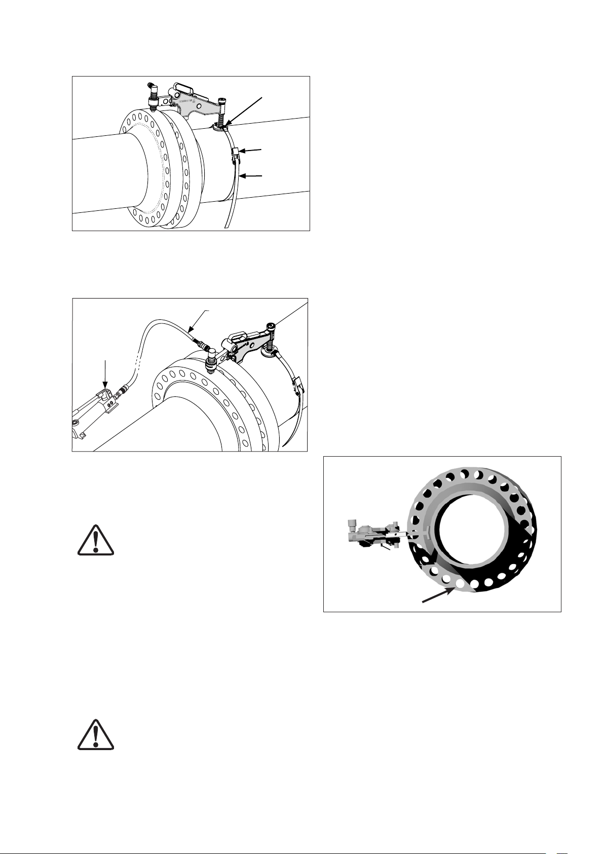
Abb. 6
Schnalle
Ratsche
Gurt
5. Schließen Sie die P-142 Hydraulikpumpe an den
Hydraulikschlauch an, und den Schlauch an den
Hydraulikzylinder. Bedienen Sie den Pumpengriff, bis
der Flansch korrekt ausgerichtet ist. (siehe Abb. 7).
Abb. 7
HydraulikHandpumpe
Hydraulikschlauch
7. Nach dem Entfernen des Werkzeugs vom Flansch,
den letzten Flanschbolzen in die verbleibende
Bolzenöffnung einsetzen und festziehen.
8.0 ROTATIONS- ODER VERDREHUNGS-
FEHLAUSRICHTUNG
Dies ist ein häufiges Problem bei Onshore- und OffshorePipeline-Installationen (siehe Abb. 8). Oft sind die Flansche
zwar ausgerichtet, aber der Bediener ist nicht in der Lage,
den Bolzen in zwei entsprechende Bolzenlöcher in den
Flanschblättern einzusetzen. Durch die Hubkraft des
ATM-9 Werkzeugs von 90 kN [9Tonnen] können Flansche
in verschiedene Richtungen bewegt werden.
Die Vorgehensweise weicht diesbezüglich lediglich in
einem einzigen Punkt ab. Das ATM-9 Werkzeug kann
am leichtesten zugänglichen Punkt des Flanschblatts
angebracht werden, da die Fehlausrichtung an allen
Bolzenlöchern gleichermaßen auftritt.
8.1 Die empfohlene Vorgehensweise ist:
1. Den günstigsten oder am besten zugänglichen Punkt am
Flanschblatt wählen und das Werkzeug dort anbringen.
(Führen Sie die Schritte 1 bis 5 in Abschnitt 7.0 aus).
2. In einer Situation, in der beide Flansche ausgerichtet
Hinweis: Der Betriebsdruck des Hydraulikzylinders des
ATM-9 Werkzeugs beträgt 700 bar [10.000 psi]. Die P-142
Hydraulikpumpe ist mit einem Druckbegrenzungsventil
ausgeführt, das sich bei ca. 724 bar [10.500 psi] öffnet.
ACHTUNG: Wenn aus irgendeinem Grund
anstelle der P-142 eine andere Pumpe
verwendet wird, sicherstellen, dass das
Druckbegrenzungsventil nicht auf eine höheren Wert als
724 bar [10.500 psi] eingestellt wird. Zur Überwachung
des Betriebsdrucks ein Druckmanometer im Kreislauf
installieren.
6. Nachdem die Ausrichtung vorgenommen wurde,
3. Den Bolzen an Punkt A in das Bolzenloch einsetzen
können die Flanschbolzen eingesetzt und festgezogen
werden. Nachdem die Bolzen in alle Bolzenöffnungen
(außer der Öffnung, in der sich der Hebehaken
befindet) eingesetzt wurden, das Werkzeug durch
4. Das ATM-9 Werkzeug kann anschließend an einer
Umkehrung der oben beschriebenen Schritte 1 bis 5
entfernen.
VORSICHT: Druckablassventil der Pumpe
öffnen, und den gesamten hydraulischen
Druck ablassen, bevor Schläuche oder
5. Nachdem die restlichen Bolzen eingesetzt sind, kann
Verschraubungen gelöst werden.
sind, aber eine Rotationsfehlausrichtung vorliegt,
kann das ATM-9 Werkzeug verwendet werden, um
die Flansche zu verschieben, bis ein Bolzenlöcherpaar
ausgerichtet ist (siehe Punkt A in Abb. 8).
Abb. 8
A
und ATM-9 lösen. Die Last wird auf den eingesetzten
Bolzen übertragen.
anderen Stelle des Flanschblatts angebracht werden
(siehe Abb. 9), um Druck auf den eingesetzten Bolzen
auszuüben. Den Hydraulikzylinder ausfahren, bis eine
oder alle Bolzenlöcher ausgerichtet sind (siehe Abb. 10).
das ATM-9 Werkzeug entfernt werden.
2929

Abb. 9
Abb. 10
überprüfen, um die Betriebsfähigkeit sicherzustellen.
• Alle fehlenden oder beschädigten Teile sind umgehend
vor der erneuten Verwendung zu ersetzen.
• Alle beweglichen Teile regelmäßig schmieren. Siehe
Abschnitt 12.0 für Schmierung und Wartung.
• Alle offenen Hydraulikkupplungen verschließen, um
das Eindringen von Schmutz zu verhindern. Darauf
achten, dass sich der Entlüftungsverschluss in der
Position "geschlossen" befindet.
• Sicherstellen, dass Rollen und Stifte abriebfrei bleiben.
• Bei Nichtverwendung alle Einzelteile zurück in den
Tragekoffer legen.
11.0 LAGERUNG
A
• Alle offenen Hydraulikkupplungen verschließen.
• Bearbeitete Oberflächen mit Fett schmieren.
• Das ATM-9 Werkzeug an einem kühlen, trockenen Ort
lagern.
12.0 SCHMIERUNG UND WARTUNG
Mobilgrease XHP™ 222 Spezialfett oder ein
gleichwertiges Hochleistungsfett der selben hohen
Qualität verwenden.
Achten Sie immer darauf, dass der Flügel des Werkzeugs
abriebfrei ist, und dass sich die Rollen frei drehen
können und gut geschmiert sind (siehe Abb. 13). Dies
verbessert die Leistung des Werkzeugs und verlängert
seine Lebensdauer.
Bitte beachten Sie, dass das ATM-9 Werkzeug in
manchen Fällen schrittweise an verschiedenen Stellen
des Flanschblatts befestigt werden muss, um die
Die Reinigung, Prüfung und Schmierung des ATM-9
Werkzeugs ist in den folgenden Schritten durchzuführen:
Fehlausrichtung zu beheben. In jedem Fall sind die
Schritte 1 bis 7 aus Abschnitt 7.0 zu befolgen.
9.0 DEMONTAGE DES ATM-9
SCHRITT 1 Das Werkzeug flach auf die Werkbank legen.
SCHRITT 2 Die zwei Spannstifte an der Vorderseite des
• Nachdem die Ausrichtung, alle Arbeiten am Flansch
und die Verschraubung, abgesehen vom Bolzenloch,
SCHRITT 3 Den Arretierungsstift des Flügels
in dem das ATM-9 Werkzeug befestigt ist, beendet
ist, kann das Werkzeug vom Flansch entfernt werden,
indem die Schritte 1 bis 5 in Abschnitt 7.0. in
umgekehrter Reihenfolge ausgeführt werden.
• Beim Entfernen vom ausgerichteten Flansch darauf
SCHRITT 4 Die Sprengringe mit einer Sprengringzange
achten, dass keine Werkzeugteile herunterfallen. Dies
verhindert Verletzungen des Personals.
Hinweis: Siehe das Ersatzteilblatt des ATM-9 Werkzeugs
SCHRITT 5 Die Rollenwellen herausziehen und die
für eine umfassende Ersatzteilliste und Montagepläne.
10.0 INSPEKTION UND PRÜFUNG
SCHRITT 6 Rollenwellen, Rollen und Lager auf Schäden
• Nach Beendigung der Arbeiten und vor erneuter
Verwendung des ATM-9 Werkzeugs, sind die
Vollständigkeit des ATM-9 Werkzeugs sowie die
verschiedenen einzelnen Teile des Werkzeugs zu
Gerätekörpers entfernen (siehe Abb. 11).
herausziehen. Den Flügel nach vorne aus
dem Gerätekörper herausziehen (siehe Abb.
12).
entfernen (siehe Abb. 13).
Rollen und Lager abnehmen und prüfen
(siehe Abb. 13).
prüfen. Falls keine Beschädigungen vorliegen, die Teile reinigen, schmieren und
wieder zusammenbauen (Schritte 1 bis 5 in
umgekehrter Reihenfolge).
3030

Abb. 11
Spannstifte
Lösung:
A. Sicherstellen, dass die Rollen frei drehbar sind, und
dass die Rollen nicht durch Schmutz oder Abrieb am
Flügel beeinträchtigt werden.
B. Sicherstellen, dass der Flügel während der Flansch-
ausrichtung nicht vollständig herausgezogen wird.
C. Sicherstellen, dass der Flügel des Werkzeugs während
der Flanschausrichtung noch um ein Stück verlängert
werden kann.
Problem 2:
Das ATM-9 Werkzeug ist angebracht und scheint richtig
zu funktionieren, aber der Flansch kann nicht ausgerichtet
werden.
Abb. 12
Flügel
Abb. 13
1
3
2
2
1. Rollen und Lager
2. Sprengringe
3. Rollenwellen
FlügelArretierungsstift
3
1
Ursache:
A. Luft im Hydrauliksystem reduziert die auf die Flansche
wirkende Kraft.
B. Die Ausrichtung des Flansches wird durch eine
Blockierung im Flanschbereich behindert. Der für die
Flanschausrichtung erforderliche Druck übersteigt die
maximale Hubkraft des ATM-9 von 9 Tonnen [90 kN].
Lösung:
A. Siehe die Entlüftungsanweisungen in Abschnitt 14.
B. Den Flanschbereich auf Blockierungen kontrollieren.
C. Wenn für die Ausrichtung des Flansches eine
Hubkapazität von mehr als 9 Tonnen [90 kN] erforderlich
ist, eine andere Methode zur Flanschausrichtung
anwenden.
14.0 ENTLÜFTEN
2
2
Die Entlüftung ist in den folgenden Schritten durchzuführen:
1. Den Entlüftungsverschluss an der Oberseite der
Hydraulikpumpe entfernen und den Hydraulikölstand
prüfen, um zu gewährleisten, dass genug Öl für die
Zylinderbewegung vorhanden ist.
2. Entlüftungsverschluss wieder anbringen, jedoch
nicht festschrauben. Der Verschluss muss sich
in der "Entlüftungsposition" befinden, um die Beund Entlüftung der Pumpe während des Betriebs
zu ermöglichen. Den Verschluss nur vollständig
festschrauben, wenn das Werkzeug nach Gebrauch
in den Tragekoffer gelegt wird.
13.0 FEHLERSUCHE UND -BEHEBUNG
3. Die Pumpe mit gelöstem Entlüftungsverschluss mit
PROBLEM 1:
Der Hydraulikzylinder rutscht während der Ausrichtung
auf das Flanschblatt des gegenüberliegenden Flansches.
4. Das Werkzeug auf eine ebene Fläche stellen, die
Ursache:
Abrieb oder Schmutz auf dem Flügel, den Rollen oder
den Lagern bei vollständig herausgezogenem Flügel.
3131
dem Hydraulikschlauch aus dem Tragekoffer an das
Werkzeug anschließen.
Hydraulikpumpe über das Werkzeug halten, das
Druckablassventil an der Pumpe schließen und
die Pumpe ansaugen lassen, sodass ein geringer
Druck anliegt und der Hydraulikzylinder vollständig
ausgefahren ist.

5. Die Hydraulikpumpe über das Werkzeug halten
und das Druckablassventil öffnen bis der Zylinder
vollständig eingefahren ist. Während der Zylinder
eingefahren wird, wird alle sich im System befindliche
Luft hoch zur Pumpe befördert und durch den
Entlüftungsverschluss abgeleitet.
6. Den obigen Vorgang drei oder vier Mal wiederholen,
um sicherzustellen, dass die gesamte Luft entfernt
und der maximale Arbeitsdruck erreicht wurde.
15.0 MINIMALE / MAXIMALE AUSZUGSLÄNGE
Siehe Abschnitt 18.0, Gewichte und Abmessungen, für
Angaben zur minimalen und maximalen Auszugslänge.
16.0 ANWENDUNGSBEREICH
Um zu bestimmen, ob sich das ATM-9 Werkzeug für die
Flanschausrichtung eignet, werden die zwei grundlegende
Dimensionen A und B verwendet. Das ATM-9 Werkzeug
kann montiert und für die Flanschausrichtung verwendet
werden, wenn die Flanschgröße der auszurichtenden
Flanschverbindung zwischen 93 mm [3,66 inch] und 228
mm [9 inch] (A) liegt und die Bolzenlochgröße 31,5 mm
[1,24 inch] oder mehr beträgt (B) (siehe Abb. 14).
Siehe die Tabellen in Abschnitt 17 mit Angaben
hinsichtlich Flanschart, -klasse und -durchmesser.
Abb. 14 – Min. und max. Flanschgrößen (optische
Darstellung)
Die Auflagerung des
Hydraulikzylinders muss
vollständig am Flanschblatt des zu
bewegenden Flansches anliegen.
Min. Abstand: 93 mm [3,66 inch]
Min. Bolzenlochgröße
31,5 mm [1,24 inch]
B
Max. Abstand: 228 mm [9 inch]
A
In dieses
Bolzenloch
einhaken
32

ATM-4 ATM-4
GEEIGNET FÜR ENERPAC ATM-2 WERKZEUG
GEEIGNET FÜR ENERPAC ATM-4 WERKZEUG
GEEIGNET FÜR ENERPAC ATM-9 WERKZEUG
NICHT FÜR ENERPAC ATM-WERKZEUGE GEEIGNET
Hinweis: Die Modelle ATM-2 und ATM-4 werden nur zu Vergleichs-
zwecken dargestellt.
ATM-2
ATM-2 ATM-4 ATM-9
5" 6" 7" 8" 9" 10" 11" 12" 13" 14" 15" 16"
4
4"
4" 5" 6" 7" 8" 9" 10" 12" 13" 14" 15" 16" 17" 18" 19" 20"
3"
2"
1"
1/2"
1/2"
1/2"
1/4"
ATM-2 ATM-4 ATM-9
3
3"
2
2"
1
1
1/2" 3/4" 1"
ATM-2 ATM-4 ATM-9
1/2"
1/2"
1/2"
1/4"
ATM-2 ATM-4 ATM-9
4" 5" 6" 7" 8" 9" 10" 12" 13" 14" 15" 16" 17" 18" 19" 20"
3
2
1
1
3
1/2"
3"
ATM-2 ATM-4 ATM-9
2
1/2"
2"
1
1/2"
1
1/4"
1"
ATM-2 ATM-4 ATM-9
ATM-2 ATM-2
4" 5" 6" 7" 8" 9" 10" 12" 13" 14" 15" 16" 17" 18" 19" 20" 21" 22" 23" 24" 26" 27" 29" 30" 33" 35" 36" 39" 42" 45" 48" 54" 60" 66" 72"
3
1/2"
4" 5" 6" 7" 8" 9" 10" 12" 13" 14" 15" 16" 17" 18" 19" 20" 21" 22" 23" 24" 29" 30" 33" 35" 36" 39" 42" 45" 48" 54" 60" 66" 72" 78" 84" 96" 108" 120"
4" 5" 6" 7" 8" 9" 10" 12" 13" 14" 15" 16" 17" 18" 19" 20" 21" 22" 23" 24" 27" 29" 30" 33" 35" 36" 39" 42" 45" 48"
3
3"
2
2"
1
1
1/2"
1/2"
1/2"
1/4"
4" 5" 6" 7" 8" 9" 10" 12" 13" 14" 15" 16" 17" 18" 19" 20" 21" 22" 23" 24" 27" 29" 30" 33" 35" 36" 39" 42" 45" 48"
3
3"
2
2"
1
1
1/2"
1/2"
1/2"
1/4"
4" 5" 6" 7" 8" 9" 10" 12" 13" 14" 15" 16" 17" 18" 19" 20" 21" 22" 23" 24"
3
3"
2
2"
1
1
1/2"
1/2"
1/2"
1/4"
ATM-2 ATM-4
4" 5" 6" 7" 8" 9" 10" 12" 13" 14" 15" 16" 17" 18" 19" 20" 21" 22" 23" 24"
3
3"
2
2"
1
1
1/2"
1/2"
1/2"
1/2"
1/4"
ATM-2 ATM-4 ATM-9
6" 7" 8" 9" 10" 11" 12" 13"
5"
4
1/2"
4"
3
1/2"
3"
2
1/2"
2"
1
1/2"
1
1/4"
ATM-2 ATM-4 ATM-9
1/2" 3/4" 1"
ATM-2 ATM-4 ATM-9
2 1-16" 2 9-16" 3 1-8" 4 1-16" 5 1-8" 7 1-16" 9" 11" 13 5-8" 16 3-4" 21 1-4"
weite
Werk-
Rohrnenn-
2K
Baureihe
ATM-2 ATM-4 ATM-9
1 13-16" 2 1-16" 2 9-16" 3 1-8" 4 1-16" 5 1-8" 7 1-16" 9" 11" 13 5-8" 16 3-4"
2 1-16" 2 9-16" 3 1-8" 4 1-16" 5 1-8" 7 1-16" 9" 11" 13 5-8" 16 3-4" 21 1-4"
zeug
Rohrnenn-
1 13-16" 2 1-16" 2 9-16" 3 1-8" 4 1-16" 5 1-8" 7 1-16" 9" 11" 13 5-8" 16 3-4"
zeug
Rohrnenn-
Baureihe
2 1-16" 2 9-16" 3 1-8" 4 1-16" 5 1-8" 7 1-16" 9" 11" 13 5-8" 16 3-4" 21 1-4"
weite
Werk-
6K
1 13-16" 2 1-16" 2 9-16" 3 1-8" 4 1-16" 5 1-8" 7 1-16" 9" 11" 13 5-8" 16 3-4"
ATM-2 ATM-4 ATM-9
zeug
Baureihe
ATM-4 ATM-9
ATM-2 ATM-4 ATM-9
weite
Werk-
3K
ATM-2 ATM-4 ATM-9
weite
Rohrnenn-
Anwendungsbereich BS10-Flansche
17.1
17.0 TABELLEN MIT DEN VERSCHIEDENEN ANWENDUNGSBEREICHEN
A
Werk-
Baureihe
zeug
Rohrnenn-
weite
D
Werk-
Baureihe
zeug
Rohrnenn-
weite
E
Werk-
Baureihe
zeug
Rohrnenn-
weite
F
Werk-
zeug
Rohrnenn-
Baureihe
weite
H
Werk-
Baureihe
zeug
Rohrnenn-
weite
J
Werk-
Baureihe
zeug
Rohrnenn-
weite
K
Werk-
Baureihe
zeug
Rohrnenn-
weite
R
Werk-
zeug
Rohrnenn-
Baureihe
weite
weite
zeug
Werk-
S
Baureihe
Werk-
Rohrnenn-
T
Baureihe
zeug
33
weite
zeug
Werk-
Rohrnenn-
Rohrnenn-
2K
Anwendungsbereich API6BX Schweißstutzen-Flansche Anwendungsbereich API6B Schweißstutzen-Flansche
17.2 17.3
Baureihe
weite
3K
Werk-
zeug
Rohrnenn-
Baureihe
weite
zeug
Werk-
6K
Baureihe

ATM-4 ATM-9
ATM-4 ATM-9
ATM-4 ATM-9
ATM-4 ATM-9
ATM-9
GEEIGNET FÜR ENERPAC ATM-2 WERKZEUG
GEEIGNET FÜR ENERPAC ATM-4 WERKZEUG
GEEIGNET FÜR ENERPAC ATM-9 WERKZEUG
NICHT FÜR ENERPAC ATM-WERKZEUGE GEEIGNET
Hinweis: Die Modelle ATM-2 und ATM-4 werden nur zu Vergleichs-
zwecken dargestellt.
22" 26" 28" 30" 32" 34" 36" 38" 40" 42" 44" 46" 48"
Rohrnenn-
Anwendungsbereich ASME B16.47 Flansche
4" 5" 6" 8" 10" 12" 14" 16" 18" 20" 24"
3
3"
2
2"
1
1
3/4" 1"
weite
1/2"
1/2"
1/2"
1/4"
Werk-
150
zeug
Baureihe
ATM-2 ATM-4
22" 26" 28" 30" 32" 34" 36" 38" 40" 42" 44" 46" 48"
weite
Werk-
Rohrnenn-
300
Baureihe
4" 5" 6" 8" 10" 12" 14" 16" 18" 20" 24"
3
1/2"
ATM-2 ATM-4 ATM-9
3"
2
1/2"
2"
1
1/2"
1
1/4"
3/4" 1"
zeug
Rohrnenn-
3
2
1
1
22" 26" 28" 30" 32" 34" 36" 38" 40" 42" 44" 46" 48"
4" 5" 6" 8" 10" 12" 14" 16" 18" 20" 24"
3"
2"
3/4" 1"
weite
1/2"
1/2"
1/2"
1/4"
Werk-
400
zeug
Baureihe
ATM-2 ATM-4 ATM-9
22" 26" 28" 30" 32" 34" 36" 38" 40" 42" 44" 46" 48"
weite
Werk-
Rohrnenn-
600
4" 5" 6" 8" 10" 12" 14" 16" 18" 20" 24"
3
1/2"
3"
2
1/2"
ATM-2 ATM-4 ATM-9
2"
1
1/2"
1
1/4"
3/4" 1"
zeug
Rohrnenn-
Baureihe
2
1
1
22" 26" 28" 30" 32" 34" 36" 38" 40" 42" 44" 46" 48"
3" 4" 5" 6" 8" 10" 12" 14" 16" 18" 20" 24"
2"
1/2" 3/4" 1"
weite
1/2"
1/2"
1/4"
Werk-
900
zeug
Baureihe
ATM-2 ATM-4 ATM-9
9
ATM-
ATM-2 ATM-4
1/2"
1/2"
ATM-2 ATM-4 ATM-9
3" 4" 5" 6" 7" 8" 10" 12" 14" 16" 18" 20" 24" 28" 32" 36" 40"
2
1/2"
2"
1
1/2"
1
1/2" 3/4" 1"
1/4"
3" 4" 5" 6" 7" 8" 10" 12" 14" 16" 18" 20"
2
2"
1
1/2"
1/2"
ATM-2 ATM-4
3" 4" 5" 6" 7" 8" 10" 12" 14" 16"
2
2"
1
3/4" 1"
1/2"
1/2"
ATM-2 ATM-4
3" 4" 5" 6" 7" 8" 10" 12" 14"
2
2"
1
1/2" 3/4" 1"
3" 4" 5" 6" 8" 10" 12" 14" 16" 18" 20" 24"
2
2"
1
1
1/2" 3/4" 1"
1/2"
1/2"
1/4"
ATM-2 ATM-4 ATM-9
3" 4" 5" 6" 8" 10" 12" 14" 16" 18" 20" 24"
2
1/2"
2"
1
1/2"
1
1/4"
ATM-2 ATM-4 ATM-9
1/2" 3/4" 1"
3" 4" 5" 6" 7" 8" 10" 12" 14" 16" 18" 20" 24" 28" 32" 36" 40" 48" 56 72" 80"
2
2"
1
1/2"
1/2"
ATM-2 ATM-4 ATM-9
3" 4" 5" 6" 7" 8" 10" 12"
2
1/2"
2"
ATM-2 ATM-4 ATM-9
1
1/2"
3/8" 1/2" 3/4" 1"
weite
Rohrnenn-
Anwendungsbereich ASME B16.5 Flansche
17.4 17.6
17.0 TABELLEN MIT DEN VERSCHIEDENEN ANWENDUNGSBEREICHEN (Fortsetzung)
Werk-
150
zeug
Baureihe
weite
Werk-
Rohrnenn-
300
Baureihe
zeug
Rohrnenn-
weite
Werk-
400
zeug
Rohrnenn-
Baureihe
weite
Werk-
600
zeug
Rohrnenn-
Baureihe
weite
Werk-
900
zeug
Rohrnenn-
Baureihe
weite
Werk1500
Baureihe
zeug
Rohrnenn-
weite
zeug
Werk2500
Baureihe
weite
Rohrnenn-
Anwendungsbereich DIN-Schweißstutzen-Flansche
17.5
zeug
WerkPN16
Baureihe
weite
Rohrnenn-
Werk-
PN25
Baureihe
zeug
Rohrnenn-
weite
Werk-
PN40
Baureihe
zeug
Rohrnenn-
weite
zeug
Werk-
PN54
Baureihe
3434
weite
Werk-
Rohrnenn-
PN100
zeug
Baureihe
weite
Werk-
Rohrnenn-
PN160
Baureihe
zeug

GEEIGNET FÜR ENERPAC ATM-2 WERKZEUG
GEEIGNET FÜR ENERPAC ATM-4 WERKZEUG
GEEIGNET FÜR ENERPAC ATM-9 WERKZEUG
NICHT FÜR ENERPAC ATM-WERKZEUGE GEEIGNET
Hinweis: Die Modelle ATM-2 und ATM-4 werden nur zu Vergleichs-
zwecken dargestellt.
4" 5" 6" 8" 10" 12" 14" 16" 18" 20" 22" 24" 26" 28" 30" 32" 34" 36" 38" 40" 42" 44" 46" 48"
3
3"
2
Rohrnenn-
17.7
Anwendungsbereich SPO-Flansche
1/2"
1/2"
weite
150
Werkzeug ATM-2 ATM-4
Baureihe
4" 5" 6" 8" 10" 12" 14" 16" 18" 20" 22" 24" 26" 28" 30" 32" 34" 36" 38" 40" 42" 44" 46" 48"
3
1/2"
3"
2
1/2"
weite
Werkzeug ATM-2 ATM-4 ATM-9
Rohrnenn-
300
3
2
Rohrnenn-
Baureihe
4" 5" 6" 8" 10" 12" 14" 16" 18" 20" 22" 24" 26" 28" 30" 32" 34" 36" 38" 40" 42" 44" 46" 48"
3"
1/2"
1/2"
weite
600
Werkzeug ATM-4 ATM-9
Baureihe
4" 5" 6" 8" 10" 12" 14" 16" 18" 20" 22" 24" 26" 28" 30" 32" 34" 36" 38" 40" 42" 44" 46" 48"
3
1/2"
3"
2
1/2"
weite
Werkzeug ATM-4 ATM-9
Rohrnenn-
900
3
2
Rohrnenn-
Baureihe
4" 5" 6" 8" 10" 12" 14" 16" 18" 20" 22" 24" 26" 28" 30" 32" 34" 36" 38" 40" 42" 44" 46" 48"
3"
1/2"
1/2"
weite
Werkzeug ATM-4 ATM-9
1500
Baureihe
4" 5" 6" 8" 10" 12" 14" 16" 18" 20" 22" 24"
3
1/2"
3"
2
1/2"
weite
Werkzeug ATM-4 ATM-9
Rohrnenn-
2500
Baureihe
4" 5" 6" 8" 10" 12" 14" 16" 18" 20" 22" 24"
3
1/2"
3"
2
1/2"
weite
Werkzeug ATM-4 ATM-9
Rohrnenn-
5000
Baureihe
4" 5" 6" 8" 10" 12" 14" 16" 18" 20" 22" 24"
3
1/2"
3"
2
1/2"
weite
Werkzeug ATM-4 ATM-9
Rohrnenn-
7500
3
2
Rohrnenn-
Baureihe
4" 5" 6" 8" 10" 12" 14" 16" 18" 20" 22" 24"
3"
1/2"
1/2"
weite
Werkzeug ATM-4 ATM-9
10000
Baureihe
4" 5" 6" 8" 10" 12" 14" 16" 18" 20" 22" 24"
3
1/2"
3"
2
1/2"
weite
Werkzeug ATM-4 ATM-9
Rohrnenn-
15000
Baureihe
17.0 TABELLEN MIT DEN VERSCHIEDENEN ANWENDUNGSBEREICHEN (Fortsetzung)
3535

18.0 GEWICHTE UND ABMESSUNGEN
Hinweis: Gewichte sind ungefähre Werte.
GEWICHT
Werkzeug mit Hydraulikzylinder und Gurt ......................................... 15,1 kg [33,3 lbs]
Handpumpe ..................................................................2,4 kg [5,3 lbs]
Hydraulikschlauch ............................................................. 1,0 kg [2,2 lbs]
Tragekoffer .................................................................. 8,9 kg [19,6 lbs]
Gesamtgewicht aller obigen Artikel .............................................. 27,4 kg [60,4 lbs]
ABMESSUNGEN
105 mm
[4.13"]
MINIMALE AUSZUGSLÄNGE
24 mm
[0.94"]
267 mm [10.51"]
521 mm [20.51"]
240 mm [9.44"]
82 mm
[3.22"]
MAXIMALE AUSZUGSLÄNGE
471 mm [18.54"]
656 mm [25.82"]
36
36

L4065 Rev. B 02/14
Foglio di istruzioni
Attrezzo oleodinamico per
l'allineamento delle flange
Modello ATM-9
Paragrafo Pagina
1.0 Istruzioni da seguire alla ricezione ........ 38
2.0 Avvertenze sulla sicurezza .............. 38
3.0 Descrizione del prodotto ............... 38
4.0 Istruzioni riguardanti la sicurezza ......... 39
5.0 Elenco degli attrezzi ................... 39
6.0 Determinazione del disallineamento ...... 39
7.0 Installazione e funzionamento ........... 40
8.0
Disallineamento della torsione e della rotazione ..
9.0 Smantellamento di ATM-9 .............. 41
41
10.0 Ispezione e collaudo ................. 42
11.0 Immagazzinaggio .................... 42
12.0 Lubrificazione e manutenzione ......... 42
13.0 Risoluzione dei problemi .............. 43
14.0 Rimozione della bolla d'aria ........... 43
15.0 Estensione minima/massima ........... 43
16.0 Area di applicazione ................. 43
17.0 Tabelle sull'area di applicazione ...... 44-46
18.0 Peso e dimensioni ................... 47
3737

1.0 ISTRUZIONI DA SEGUIRE ALLA RICEZIONE
Ispezionare visivamente tutti i componenti alla ricerca di
eventuali danni. I danni causati dalla spedizione non sono
coperti da garanzia. Se si constata la presenza di danni
dovuti alla spedizione li si dovrà notificare immediatamente al
vettore. Il vettore è responsabile di tutti i costi di riparazione
e sostituzione conseguenti a un danno avvenuto durante la
spedizione.
parti mobili di macchinario, bordi taglienti e agenti chimici corrosivi.
AVVERTENZA: Non sovraccaricare le apparecchiature. I sovraccarichi sono causa di guasti alle
apparecchiature e possono comportare il rischio
di lesioni personali.
CAUTELA: Accertarsi che tutti i componenti
dell’impianto siano protetti da cause esterne di
danneggiamento, quali calore eccessivo, fiamme,
La sicurezza anzitutto
Leggere accuratamente tutte le istruzioni, gli avvisi e le
avvertenze. Seguire tutte le prescrizioni di sicurezza per
evitare danni a persone o cose durante il funzionamento
dell’impianto. Enerpac non si assume alcuna responsabilità
per danni o lesioni derivanti da un uso pericoloso del prodotto,
dalla mancanza di manutenzione o dal funzionamento
non appropriato del prodotto e/o dell’impianto. Contattare
Enerpac qualora si abbiano dubbi concernenti le precauzioni
e gli interventi relativi alla sicurezza. Per salvaguardare la
garanzia, usare esclusivamente olio idraulico ENERPAC.
Una segnalazione di CAUTELA viene usata per le corrette
pratiche e procedure di funzionamento e manutenzione
atte a prevenire il danneggiamento o la distruzione di
apparecchiature o altri oggetti.
La segnalazione AVVERTENZA indica un pericolo potenziale
che necessita di pratiche o procedure corrette per evitare
lesioni alle persone.
2.0 RACCOMANDAZIONI PER LA SICUREZZA
La mancata osservanza delle seguenti
segnalazioni che richiedono cautela e
delle seguenti avvertenze può causare
danni alle apparecchiature e lesioni alle persone.
IMPORTANTE: L’operatore deve avere un’età
non inferiore a 18 anni. L’operatore deve inoltre
aver letto e ben compreso tutte le istruzioni, le
raccomandazioni per la sicurezza, le avvertenze e le
segnalazioni di pericolo prima di cominciare ad azionare
l’apparecchiatura Enerpac. L’operatore è il responsabile di
tale attività nei confronti di terzi.
AVVERTENZA: Per evitare il rischio di lesioni
personali e di danni alle apparecchiature, verificare
che tutti i componenti idraulici sopportino la
pressione massima di 700 bar [10.000 psi].
IMPORTANTE: Ridurre il rischio di sovraccarichi.
A livello di ogni impianto idraulico, utilizzare dei
manometri idraulici atti a indicare i carichi operativi
utilizzabili in sicurezza: è il modo sicuro di verificare
costantemente ciò che succede a livello dell’impianto.
nell’apparecchiatura e per sopportare i carichi nominali.
lavorazione.
uenti gravi lesioni. In caso di penetrazione di olio
nell’epidermide, consultare immediatamente un medico.
sicurezza.
atrici quadrate o esagonali per allentare o stringere bulloni e
dadi. Enerpac fornisce anche degli spaccadadi da usare qualora non si riesca a rimuovere un dado.
3.0 DESCRIZIONE DEL PRODOTTO
L'attrezzo di allineamento ATM-9 è stato progettato per
essere utilizzato nelle tipiche procedure di manutenzione e
installazione. Consente di correggere l'allineamento delle
flange grazie a una capacità fisica pari a 9 tonnellate (90 kN).
CAUTELA: Evitare gomiti di piccolo raggio e
piegature brusche che sono causa di notevoli
contropressioni nei tubi flessibili. Gomiti e piegature comportano un’usura prematura dei flessibili.
AVVERTENZA: Sostituire immediatamente i pezzi
usurati o danneggiati con pezzi di ricambio originali Enerpac. I pezzi di ricambio Enerpac sono
progettati per inserirsi perfettamente
AVVERTENZA: Indossare sempre occhiali protettivi. L’operatore deve prendere appropriate precauzioni per evitare lesioni causate da cedimento
e/o malfunzionamento dell’attrezzo o del pezzo in
PERICOLO: Non maneggiare i tubi flessibili in
pressione. L’olio in pressione che fuoriesce
potrebbe penetrare nell’epidermide, con conseg-
AVVERTENZA: Evitare tassativamente di pressurizzare gli accoppiatori non collegati. Nei sistemi accoppiati, utilizzare unicamente apparecchiature idrauliche.
IMPORTANTE: NON sollevare l’apparecchiatura
idraulica utilizzando tubi flessibili o accoppiatori.
A tale scopo, utilizzare la maniglia di trasporto o
altri mezzi per effettuare un trasporto in completa
Si consiglia l’uso degli appositi liquidi o spray per
facilitare lo scorrimento delle parti mobili. Le chiavi
oleodinamiche Enerpac sono dotate di unità azion-
3838

Ad esempio, può essere usato per agevolare la sostituzione
dei giunti ad anello o di altro tipo.
del personale di supporto sono di primaria importanza, così
come quella di tutti i presenti, pubblico incluso.
L'attrezzo oleodinamico ATM-9 viene azionato da un cilindro
idraulico e da una pompa manuale. La massima pressione
operativa è di 10.000 psi (700 bar).
Queste istruzioni hanno il solo scopo di garantire il
funzionamento sicuro dell'attrezzo ATM-9 durante le normali
operazioni di manutenzione e installazione. Tutti gli altri aspetti
legati alla sicurezza devono essere controllati dall'addetto alla
Attenendosi a queste istruzioni, sarà possibile ottenere un
supervisione.
funzionamento sicuro ed estendere al massimo la durata
dell'attrezzo. Prima di utilizzare l'attrezzo, è necessario
leggere tutte le sezioni del presente manuale di istruzioni.
3.1 Caratteristiche e componenti principali
Figura 1
Cilindro
idraulico
Attrezzo
ATM-9
Supporto a
discesa
l'attrezzo è installato, potrebbe verificarsi un sovraccarico e la
forza risultante potrebbe risultare superiore al carico consentito
per l'attrezzo.
5.0 ELENCO DEGLI ATTREZZI
Il set di utensili comprende:
Tubo flessibile
idraulico
• attrezzo di allineamento ATM-9 con cilindro idraulico;
• tubo flessibile idraulico lungo 1,8 m;
• pompa manuale idraulica P-142;
• attacchi NPTF da 3/8" su tubo flessibile, cilindro e pompa;
• cricchetto e cinghia;
• manuale di istruzioni;
• custodia.
ATTENZIONE: l'attrezzo ATM-9 non deve essere
collegato all'effusore di un recipiente in pressione.
AVVERTENZA: mai collegare ATM-9 a un giunto
prima che i bulloni della flangia siano stati svitati
e rimossi. Se i bulloni vengono rimossi mentre
Cinghia
Pompa idraulica P-142
3.2 Dati tecnici
Descrizione dell'attrezzo:
attrezzo oleodinamico per
l'allineamento della rotazione
e delle flange fisse.
Nota: per conoscere i pesi e le dimensioni, fare riferi-
mento alla sezione 18.0.
Forza di allineamento:
9,0 tonnellate (90 kN)
da 10.000 psi (700 bar) di
pressione idraulica.
4.0 ISTRUZIONI RIGUARDANTI LA SICUREZZA
IMPORTANTE: per tutte le installazioni è necessario rispettare i
requisiti di sicurezza del sito. La sicurezza dell'operatore e quella
Nota: tutti i componenti idraulici supportano il
funzionamento a 10.000 psi (700 bar).
6.0 PROCEDURA DI DETERMINAZIONE DEL
DISALLINEAMENTO
• ATM-9 non deve essere collegato a un giunto flangiato prima
che sia stata effettuata la procedura di determinazione del
disallineamento. Fare riferimento all'avvertenza presente
nella sezione 4.0.
• Svitare e rimuovere tutti i bulloni in posizioni pari.
Continuare con questa procedura. Il disallineamento
potrebbe non presentarsi fino al momento in cui non
saranno rimasti pochi bulloni. A questo punto la direzione
del disallineamento dovrebbe essere palese.
• ATM-9, una volta collegato, spingerà direttamente contro il
disallineamento, allineando nuovamente il giunto.
Esempio: disallineamento in varie direzioni
Un giunto flangiato guasto può causare il disallineamento in
qualsiasi punto e in qualunque direzione.
Vedere la Figura 2. ATM-9 deve essere collegato al punto di
massimo disallineamento, ossia A o B. Gli esempi illustrano il
punto in cui ATM-9 deve essere collegato.
3939

Figura 2
4. Fissare il gancio della cinghia facendolo passare attraverso
una delle aperture presenti sulla fibbia (sopra il cuscinetto
del supporto a discesa). Infilare il gancio del cricchetto
nell'altra apertura presente sul lato opposto della fibbia.
Fare scorrere l'estremità della cinghia attraverso il
cricchetto e stringerla. (vedere la Figura 6).
Figura 5
Cilindro
idraulico
7.0 INSTALLAZIONE E FUNZIONAMENTO
1. Determinare i punti di massimo disallineamento (vedere
la Figura 3). Come indicato dalle frecce, i punti massimi si
trovano nella parte superiore o in quella inferiore del giunto.
Figura 3
Punto di
massimo
disallineamento
Punto di
massimo
disallineamento
Figura 6
2. Posizionare il gancio di sollevamento dell'attrezzo nel
foro del bullone al punto di massimo disallineamento,
quindi regolare il supporto a discesa sul tubo, ruotando la
manopola in senso orario (vedere la Figura 4).
Aletta
Perno di blocco
dell'aletta
Fibbia
Cricchetto
Cinghia
Figura 4
Manopola
di regolazione
5. Collegare la pompa idraulica P-142 al tubo flessibile
idraulico e quest'ultimo al cilindro idraulico. Azionare
Gancio per
il sollevamento
Supporto
a discesa
l'impugnatura della pompa finché il giunto non sarà
allineato. (vedere la Figura 7).
Figura 7
Pompa manuale idraulica
Nota: durante la regolazione l'attrezzo deve essere tenuto
allo stesso livello del bullone. L'attrezzo deve rimanere
sempre parallelo al tubo.
3. Tirare il perno di blocco ed estendere l'aletta alla distanza
desiderata (vedere la Figura5). Ruotare il cilindro in senso
orario fino a posizionarlo sulla superficie della flangia
opposta. A questo punto, assicurarsi che l'attrezzo si trovi
su una superficie uniforme e che l'estremità del cilindro sia
perfettamente a contatto con la flangia superiore.
Nota: il cilindro idraulico dell'attrezzo ATM-9 supporta una
pressione operativa pari a 10,000 psi (700 bar). La pompa
idraulica P-142 contiene una valvola di sicurezza integrata che
si apre a circa 10.500 psi (724 bar).
40
Tubo flessibile idraulico

AVVERTENZA: se per qualunque ragione viene
utilizzata una pompa diversa da P-142, assicurarsi
che la valvola di scarico della pompa non sia
impostata oltre i 10.500 psi (724 bar). Installare un manometro
nel circuito per monitorare la pressione del sistema.
3. Inserire il bullone nell'apposito foro al punto A, quindi
rilasciare l'attrezzo ATM-9. Il carico si trasferirà sul bullone
inserito.
4. A questo punto è possibile collegare ATM-9 in un altro
punto della circonferenza del giunto (vedere la Figura
9) premendo contro il bullone inserito. Fare avanzare il
6. Una volta completato l'allineamento, è possibile inserire e
stringere i bulloni della flangia. Dopo avere riposizionato tutti i
bulloni nei fori disponibili (fatta eccezione per il foro nel quale
è inserito il gancio per il sollevamento dell'attrezzo), rimuovere
cilindro idraulico finché un'altra coppia o tutte le coppie di
fori per bulloni saranno parallele (vedere la Figura 10).
5. Una volta inseriti i restanti bulloni, è possibile rimuovere
l'attrezzo ATM-9.
l'attrezzo e seguire i passaggi 1-5 nell'ordine inverso.
ATTENZIONE: Aprire la valvola di scarico e
Figura 9
assicurarsi che tutta la pressione idraulica sia stata
espulsa prima di scollegare tubi flessibili e raccordi.
7. Una volta rimosso l'attrezzo dalla flangia, inserire e avvitare
l'ultimo bullone della flangia nel foro rimanente.
8.0 DISALLINEAMENTO DELLA TORSIONE E DELLA
ROTAZIONE
Si tratta di un problema comune nelle installazioni di tubature
di terra e offshore (vedere la Figura 8). Spesso accade che
le flange siano allineate ma l'operatore non riesca a inserire
il bullone in nessuna coppia di fori corrispondenti sulla
circonferenza del giunto. ATM-9, con una capacità di 90 kN
(9 tonnellate), riesce a controllare le flange in varie direzioni.
Figura 10
A
La procedura di installazione corrisponde a quella descritta
in precedenza, con una possibile eccezione. ATM-9 può
essere collegato al punto più accessibile sulla circonferenza
del giunto, poiché il disallineamento interessa tutti i fori del
bullone allo stesso modo.
8.1 Le procedure operative consigliate sono le seguenti:
1. Individuare il punto più comodo o accessibile sulla
circonferenza del giunto e collegare l'attrezzo (seguire i
passaggi 1-5 della sezione 7.0).
2. Qualora entrambe le flange siano allineate ma sia presente
un disallineamento della rotazione, l'attrezzo ATM-9 verrà
usato per spingere le flange oltre l'allineamento fino a rendere
paralleli due fori per bulloni (vedere il punto A nella Figura 8).
Si prega di notare che, in alcune situazioni, l'operatore
potrebbe dover "cercare" il disallineamento lungo la
circonferenza e collegare l'attrezzo ATM-9 in varie posizioni
per correggerlo. In ogni caso, è necessario seguire le
Figura 8
procedure descritte nei passaggi 1-7 della sezione 7.0.
9.0 SMANTELLAMENTO DI ATM-9
• Una volta raggiunto l'allineamento, le operazioni sul giunto
e sui bulloni sono terminate (fatta eccezione per il foro in
cui si trova l'attrezzo ATM-9). È quindi possibile rimuovere
l'attrezzo dal giunto seguendo i passaggi 1-5 della sezione
7.0 nell'ordine inverso.
• Fare attenzione a non fare cadere nessun componente
durante la rimozione dal giunto allineato. Questa precauzione
A
consente di evitare di causare lesioni al personale.
4141

Nota: per un elenco completo dei componenti e i diagrammi di
PASSAGGIO 6. Verificare che gli alberi portarullo, i rulli e i
assemblaggio, fare riferimento alla scheda dei ricambi di ATM-9.
10.0 ISPEZIONE E COLLAUDO
• Al termine dell'operazione e prima di rimettere in servizio
l'attrezzo, è necessario appurare l'integrità di quest'ultimo
Figura 11
ed esaminare i vari elementi per accertarsi che siano in
buono stato.
• Tutti gli elementi mancanti o danneggiati devono essere
sostituiti appena possibile e prima che l'attrezzo venga
riutilizzato.
• Ungere regolarmente tutte le parti mobili. Fare riferimento
alla sezione 12.0 Lubrificazione e manutenzione.
• Coprire o tappare tutti i raccordi idraulici aperti per evitare
l'ingresso di sporcizia. Assicurarsi che il coperchio della
presa d'aria della pompa sia chiuso.
• Accertarsi che i rulli e i perni rimangano privi di graniglia.
• Riposizionare tutti gli elementi non utilizzati all'interno della
custodia.
cuscinetti non siano danneggiati. Qualora
non vengano riscontrati danni, pulire, ungere
e riassemblare i componenti (seguire i
passaggi 1-5 nell'ordine inverso).
Perni a molla
11.0 IMMAGAZZINAGGIO
Figura 12
• Coprire o tappare tutti i raccordi idraulici aperti.
• Ungere le superfici lavorate con il grasso.
• Conservare l'attrezzo ATM-9 in un luogo fresco e asciutto.
12.0 LUBRIFICAZIONE E MANUTENZIONE
Utilizzare il grasso Mobilgrease XHP™ 222 o un grasso
equivalente di ottima qualità per supporti usati con carichi
pesanti.
Controllare sempre che l'aletta dell'attrezzo sia priva di graniglia
e che i rulli ruotino correttamente e siano ben lubrificati (vedere
la Figura 13). Questo migliorerà le prestazioni dell'attrezzo e
contribuirà a prolungarne la durata.
Pulire, ispezionare e lubrificare l'attrezzo ATM-9 come
Figura 13
descritto nei passaggi esposti di seguito:
PASSAGGIO 1. Appoggiare l'attrezzo orizzontalmente sul
banco di lavoro.
PASSAGGIO 2. Rimuovere i due perni a molla sulla parte
frontale del corpo centrale (vedere la Figura
11).
PASSAGGIO 3. Tirare il perno di blocco dell'aletta verso
l'esterno. Rimuovere l'aletta dal corpo
principale facendola scivolare in avanti
(vedere la Figura 12).
PASSAGGIO 4. Rimuovere gli anelli elastici utilizzando le
1. Rulli e cuscinetti
2. Anelli elastici
3. Alberi portarullo
apposite pinze (vedere la Figura 13).
Aletta
Perno di blocco
dell'aletta
1
2
2
3
2
3
2
1
PASSAGGIO 5. Far scivolare gli alberi portarullo verso
l'esterno per rimuovere e quindi esaminare i
rulli e i cuscinetti (vedere la Figura 13).
4242

13.0 RISOLUZIONE DEI PROBLEMI
4. Posizionare l'attrezzo in verticale su una superficie piana,
tenere la pompa idraulica sopra l'attrezzo, chiudere la
Problema 1:
Il cilindro idraulico scivola sulla circonferenza della flangia
opposta mentre ATM-9 allinea il giunto.
valvola di scarico presente sulla pompa e adescare la
pompa per fare avanzare completamente il cilindro idraulico
e raggiungere una lieve pressione.
Causa:
presenza di graniglia o sporcizia sull'aletta, sui rulli o sui cuscinetti con l'aletta alla massima estensione.
5. Tenendo la pompa idraulica sopra lo strumento, aprire
la valvola di scarico consentendo al cilindro di rientrare
completamente. Mentre il cilindro arretra, l'aria presente nel
sistema verrà spinta verso la pompa e scaricata attraverso
Soluzione:
il coperchio della presa d'aria.
A. Assicurarsi che i rulli ruotino liberamente e che non
siano presenti impedimenti tra questi ultimi e le superfici
dell'aletta, come ad esempio sporcizia o graniglia.
B. Verificare che l'aletta non si trovi alla massima estensione
6. Ripetere la procedura appena descritta tre o quattro volte
cosicché l'aria venga rimossa e l'attrezzo raggiunga la
piena pressione di esercizio.
quando si allinea il giunto.
C. Controllare che sia rimasta un'estensione tale da consentire
15.0 ESTENSIONE MINIMA/MASSIMA
all'attrezzo ATM-9 di espandersi una volta allineato il
giunto.
Per informazioni sull'estensione massima e quella minima, fare
riferimento alla sezione 18.0 Peso e dimensioni.
Problema 2:
L'attrezzo ATM-9 è collegato e sembra funzionare corretta-
16.0 AREA DI APPLICAZIONE
mente, ma il giunto non si allinea.
Due dimensioni di base, A e B, determineranno se sia possibile
Causa:
A. È possibile che nel sistema idraulico sia presente dell'aria
che limita la forza sulle flange.
B. Potrebbe esserci qualcosa che impedisce il movimento
del giunto nei pressi delle flange. Per allineare il giunto
potrebbe essere necessaria una pressione superiore a 9
utilizzare l'attrezzo ATM-9 per allineare il giunto. Se il giunto
della flangia da allineare è compreso tra 3,66" (93 mm) e 9" (228
mm), come illustrato al punto (A) e presenta un foro del bullone
di larghezza uguale o superiore a 1,24" (31,5 mm), come
illustrato al punto (B), è possibile collegare l'attrezzo ATM-9 ed
effettuare l'allineamento (vedere la Figura 14).
tonnellate (90 kN).
Consultare i grafici suddivisi per tipo di flangia, classe e
Soluzione:
A. Consultare le istruzioni per la rimozione della bolla d'aria
nella sezione 14.
B. Verificare che non siano presenti ostruzioni nei pressi del
giunto.
C. Se l'allineamento del giunto richiede una forza superiore
alla capacità dell'attrezzo, ossia 9 tonnellate (90 kN), è
necessario adottare un altro metodo per allineare il giunto.
14.0 RIMOZIONE DELLA BOLLA D'ARIA
diametro riportati nella sezione 17.
Figura 14 – Dimensioni minime e massime della flangia (immagine)
La sede del cilindro idraulico
deve poggiare completamente
sulla circonferenza della
flangia da spingere.
Dimensione minima
del foro del bullone
1,24" (31,5 mm)
Rimuovere l'aria come descritto nei seguenti passaggi:
1. Rimuovere il coperchio della presa d'aria sulla parte
superiore della pompa idraulica e controllare che il livello
dell'olio idraulico sia sufficiente per fare avanzare il cilindro.
B
Distanza minima 3,66" (93 mm)
Distanza massima 9" (228 mm)
A
Il gancio entra
in questo
foro del bullone
2. Sostituire il coperchio della presa d'aria, ma non stringerlo.
Il coperchio deve essere allentato (in posizione "di sfiato")
affinché l'aria entri nella pompa ed esca durante l'utilizzo.
Quando, dopo l'uso, si riposiziona l'attrezzo nella custodia,
il coperchio deve essere stretto del tutto.
3. Tenendo il coperchio della presa d'aria allentato, collegare
la pompa all'attrezzo utilizzando il tubo flessibile idraulico
nella custodia.
4343

ENERPAC
ADATTO ALL'USO CON L'ATTREZZO ATM-2 DI ENERPAC
NON ADATTO ALL'USO CON GLI ATTREZZI ATM DI
ADATTO ALL'USO CON L'ATTREZZO ATM-4 DI ENERPAC
ADATTO ALL'USO CON L'ATTREZZO ATM-9 DI ENERPAC
Nota: i modelli ATM-2 e ATM-4 sono illustrati a puro titolo
di riferimento.
ATM-4 ATM-4
ATM-2
Attrezzo ATM-2 ATM-4 ATM-9
connessione
3K
Classe
2 1-16" 2 9-16" 3 1-8" 4 1-16" 5 1-8" 7 1-16" 9" 11" 13 5-8" 16 3-4" 21 1-4"
Misura no-
minale tubo/
connessione
6K
1 13-16" 2 1-16" 2 9-16" 3 1-8" 4 1-16" 5 1-8" 7 1-16" 9" 11" 13 5-8" 16 3-4"
Attrezzo ATM-2 ATM-4 ATM-9
Classe
2 1-16" 2 9-16" 3 1-8" 4 1-16" 5 1-8" 7 1-16" 9" 11" 13 5-8" 16 3-4" 21 1-4"
Misura no-
minale tubo/
5" 6" 7" 8" 9" 10" 11" 12" 13" 14" 15" 16"
4
4"
3
4" 5" 6" 7" 8" 9" 10" 12" 13" 14" 15" 16" 17" 18" 19" 20"
4" 5" 6" 7" 8" 9" 10" 12" 13" 14" 15" 16" 17" 18" 19" 20" 21" 22" 23" 24" 27" 29" 30" 33" 35" 36" 39" 42" 45" 48"
3
3"
2
2"
4" 5" 6" 7" 8" 9" 10" 12" 13" 14" 15" 16" 17" 18" 19" 20" 21" 22" 23" 24" 29" 30" 33" 35" 36" 39" 42" 45" 48" 54" 60" 66" 72" 78" 84" 96" 108" 120"
1
1
4" 5" 6" 7" 8" 9" 10" 12" 13" 14" 15" 16" 17" 18" 19" 20" 21" 22" 23" 24" 26" 27" 29" 30" 33" 35" 36" 39" 42" 45" 48" 54" 60" 66" 72"
3
1/2"
1/2"
1/2"
1/2"
1/4"
4" 5" 6" 7" 8" 9" 10" 12" 13" 14" 15" 16" 17" 18" 19" 20" 21" 22" 23" 24" 27" 29" 30" 33" 35" 36" 39" 42" 45" 48"
3
3"
2
2"
1
1
1/2"
1/2"
1/2"
1/4"
4" 5" 6" 7" 8" 9" 10" 12" 13" 14" 15" 16" 17" 18" 19" 20" 21" 22" 23" 24"
3
1/2"
3
3"
2
1/2"
2
2"
1
1
1/2"
1/4"
1
1
4" 5" 6" 7" 8" 9" 10" 12" 13" 14" 15" 16" 17" 18" 19" 20" 21" 22" 23" 24"
3"
2"
1/2"
1/2"
1/2"
1/4"
3
3"
2
2"
1
1
1"
1/2"
1/2"
1/2"
1/4"
4" 5" 6" 7" 8" 9" 10" 12" 13" 14" 15" 16" 17" 18" 19" 20"
3
3"
2
2"
1
1
1"
1/2"
1/2"
1/2"
1/4"
3"
2
2"
1
1
1/2" 3/4" 1"
1/2"
1/2"
1/2"
1/2"
1/4"
5" 6" 7" 8" 9" 10" 11" 12" 13"
4
1/2"
4"
3
1/2"
3"
2
1/2"
2"
1
1/2"
1
1/4"
ATM-2 ATM-4 ATM-9
1/2" 3/4" 1"
1 13-16" 2 1-16" 2 9-16" 3 1-8" 4 1-16" 5 1-8" 7 1-16" 9" 11" 13 5-8" 16 3-4"
Attrezzo ATM-2 ATM-4 ATM-9
connessione
2K
Classe
2 1-16" 2 9-16" 3 1-8" 4 1-16" 5 1-8" 7 1-16" 9" 11" 13 5-8" 16 3-4" 21 1-4"
Misura no-
minale tubo/
1 13-16" 2 1-16" 2 9-16" 3 1-8" 4 1-16" 5 1-8" 7 1-16" 9" 11" 13 5-8" 16 3-4"
Misura no-
Misura no-
Attrezzo ATM-2 ATM-2
minale tubo/
connessione
Classe A
Area di applicazione della fl angia BS10
17.1
17.0 TABELLE SULL'AREA DI APPLICAZIONE
Attrezzo ATM-2 ATM-4 ATM-9
minale tubo/
connessione
Classe D
Misura no-
minale tubo/
connessione
Misura no-
Attrezzo ATM-2 ATM-4 ATM-9
minale tubo/
Classe E
Attrezzo ATM-2 ATM-4 ATM-9
connessione
Classe F
Misura no-
minale tubo/
connessione
Misura no-
Attrezzo ATM-2 ATM-4
minale tubo/
Classe H
Attrezzo ATM-2 ATM-4 ATM-9
connessione
Classe J
Misura no-
minale tubo/
connessione
44
Misura no-
Attrezzo ATM-2 ATM-4 ATM-9
minale tubo/
Classe K
Attrezzo ATM-2 ATM-4 ATM-9
connessione
Classe R
Misura no-
minale tubo/
connessione
Misura no-
Attrezzo ATM-2 ATM-4 ATM-9
minale tubo/
Classe S
Attrezzo
connessione
Classe T
Misura no-
Area di applicazione della fl angia da saldare di testa API6BX Area di applicazione della fl angia da saldare di testa API6B
17.2 17.3
Attrezzo ATM-2 ATM-4 ATM-9
minale tubo/
connessione
2K
Classe
Misura no-
Attrezzo ATM-2 ATM-4 ATM-9
minale tubo/
connessione
3K
Classe
Misura no-
minale tubo/
connessione
6K
Attrezzo ATM-4 ATM-9
Classe

ADATTO ALL'USO CON L'ATTREZZO ATM-2 DI ENERPAC
ADATTO ALL'USO CON L'ATTREZZO ATM-4 DI ENERPAC
ADATTO ALL'USO CON L'ATTREZZO ATM-9 DI ENERPAC
NON ADATTO ALL'USO CON GLI ATTREZZI ATM DI ENERPAC
Nota: i modelli ATM-2 e ATM-4 sono illustrati a puro titolo
di riferimento.
22" 26" 28" 30" 32" 34" 36" 38" 40" 42" 44" 46" 48"
Misura no-
minale tubo/
Area di applicazione della fl angia ASME B16.47
4" 5" 6" 8" 10" 12" 14" 16" 18" 20" 24"
3
3"
2
2"
1
1
3/4" 1"
Attrezzo ATM-4 ATM-9
connessione
150
Classe
1/2"
1/2"
1/2"
1/4"
22" 26" 28" 30" 32" 34" 36" 38" 40" 42" 44" 46" 48"
Misura no-
minale tubo/
connessione
4" 5" 6" 8" 10" 12" 14" 16" 18" 20" 24"
3
1/2"
3"
2
1/2"
2"
1
1/2"
1
1/4"
3/4" 1"
Attrezzo ATM-4 ATM-9
300
Classe
22" 26" 28" 30" 32" 34" 36" 38" 40" 42" 44" 46" 48"
Misura no-
minale tubo/
connessione
4" 5" 6" 8" 10" 12" 14" 16" 18" 20" 24"
3
1/2"
3"
2
1/2"
2"
1
1/2"
1
1/4"
3/4" 1"
Attrezzo ATM-4 ATM-9
400
Classe
22" 26" 28" 30" 32" 34" 36" 38" 40" 42" 44" 46" 48"
Misura no-
minale tubo/
connessione
4" 5" 6" 8" 10" 12" 14" 16" 18" 20" 24"
3
1/2"
3"
2
1/2"
2"
1
1/2"
1
1/4"
3/4" 1"
Attrezzo ATM-4 ATM-9
600
Classe
22" 26" 28" 30" 32" 34" 36" 38" 40" 42" 44" 46" 48"
Misura no-
minale tubo/
connessione
900
3" 4" 5" 6" 8" 10" 12" 14" 16" 18" 20" 24"
2
1/2"
2"
1
1/2"
1
1/4"
1/2" 3/4" 1"
Attrezzo ATM-9
Classe
9
ATM-
1/2"
1/2"
3" 4" 5" 6" 7" 8" 10" 12" 14" 16" 18" 20" 24" 28" 32" 36" 40"
2
1/2"
2"
1
1/2"
1
1/4"
3" 4" 5" 6" 7" 8" 10" 12" 14" 16" 18" 20"
2
1/2"
3" 4" 5" 6" 7" 8" 10" 12" 14" 16"
2
2"
1
1/2"
1/2"
3" 4" 5" 6" 7" 8" 10" 12" 14"
2
2"
1
2"
1
1/2" 3/4" 1"
1/2"
3/4" 1"
1/2" 3/4" 1"
3" 4" 5" 6" 8" 10" 12" 14" 16" 18" 20" 24"
2
2"
1
1
1/2"
1/2"
1/4"
3" 4" 5" 6" 8" 10" 12" 14" 16" 18" 20" 24"
2
1/2"
2"
1
1/2"
1
1/4"
3" 4" 5" 6" 7" 8" 10" 12" 14" 16" 18" 20" 24" 28" 32" 36" 40" 48" 56 72" 80"
2
2"
1/2" 3/4" 1"
1/2" 3/4" 1"
1
1/2"
1/2"
3" 4" 5" 6" 7" 8" 10" 12"
2
1/2"
2"
1
1/2"
3/8" 1/2" 3/4" 1"
Misura no-
Area di applicazione della fl angia ASME B16.5
17.4 17.6
17.0 TABELLE SULL'AREA DI APPLICAZIONE (continua)
Attrezzo ATM-2 ATM-4
minale tubo/
connessione
150
Classe
Misura no-
minale tubo/
connessione
Attrezzo ATM-2 ATM-4 ATM-9
300
Classe
Misura no-
minale tubo/
connessione
Attrezzo ATM-2 ATM-4 ATM-9
400
Classe
Misura no-
minale tubo/
connessione
Attrezzo ATM-2 ATM-4 ATM-9
600
Classe
Misura no-
minale tubo/
connessione
900
Attrezzo ATM-2 ATM-4 ATM-9
Classe
Misura no-
minale tubo/
connessione
Attrezzo ATM-2 ATM-4 ATM-9
1500
Classe
Misura no-
minale tubo/
connessione
Attrezzo ATM-2 ATM-4 ATM-9
2500
Classe
4545
Misura no-
Attrezzo ATM-2 ATM-4 ATM-9
minale tubo/
connessione
PN16
Classe
Area di applicazione della fl angia da saldare di testa DIN
17.5
Misura no-
minale tubo/
connessione
Attrezzo ATM-2 ATM-4
PN25
Classe
Misura no-
minale tubo/
connessione
Attrezzo ATM-2 ATM-4
PN40
Classe
Misura no-
minale tubo/
connessione
Attrezzo ATM-2 ATM-4
PN54
Classe
Misura no-
minale tubo/
connessione
Attrezzo ATM-2 ATM-4 ATM-9
PN100
Classe
Misura no-
minale tubo/
connessione
Attrezzo ATM-2 ATM-4 ATM-9
PN160
Classe

ADATTO ALL'USO CON L'ATTREZZO ATM-2 DI ENERPAC
ADATTO ALL'USO CON L'ATTREZZO ATM-4 DI ENERPAC
ADATTO ALL'USO CON L'ATTREZZO ATM-9 DI ENERPAC
NON ADATTO ALL'USO CON GLI ATTREZZI ATM DI ENERPAC
Nota: i modelli ATM-2 e ATM-4 sono illustrati a puro titolo
di riferimento.
4" 5" 6" 8" 10" 12" 14" 16" 18" 20" 22" 24" 26" 28" 30" 32" 34" 36" 38" 40" 42" 44" 46" 48"
3
3"
2
Misura
nominale tubo/
17.7
Area di applicazione della fl angia SPO
1/2"
1/2"
Attrezzo ATM-2 ATM-4
connessione
150
Classe
4" 5" 6" 8" 10" 12" 14" 16" 18" 20" 22" 24" 26" 28" 30" 32" 34" 36" 38" 40" 42" 44" 46" 48"
3
1/2"
3"
2
1/2"
Misura
Attrezzo ATM-2 ATM-4 ATM-9
connessione
nominale tubo/
300
Classe
4" 5" 6" 8" 10" 12" 14" 16" 18" 20" 22" 24" 26" 28" 30" 32" 34" 36" 38" 40" 42" 44" 46" 48"
3
1/2"
3"
2
1/2"
Misura
Attrezzo ATM-4 ATM-9
connessione
nominale tubo/
600
Classe
4" 5" 6" 8" 10" 12" 14" 16" 18" 20" 22" 24" 26" 28" 30" 32" 34" 36" 38" 40" 42" 44" 46" 48"
3
1/2"
3"
2
1/2"
Misura
Attrezzo ATM-4 ATM-9
connessione
nominale tubo/
900
Classe
4" 5" 6" 8" 10" 12" 14" 16" 18" 20" 22" 24" 26" 28" 30" 32" 34" 36" 38" 40" 42" 44" 46" 48"
3
1/2"
3"
2
1/2"
Misura
Attrezzo ATM-4 ATM-9
connessione
nominale tubo/
1500
Classe
4" 5" 6" 8" 10" 12" 14" 16" 18" 20" 22" 24"
3
1/2"
3"
2
1/2"
Misura
connessione
nominale tubo/
2500
17.0 TABELLE SULL'AREA DI APPLICAZIONE (continua)
4646
Misura
Attrezzo ATM-4 ATM-9
Classe
4" 5" 6" 8" 10" 12" 14" 16" 18" 20" 22" 24"
3
1/2"
3"
2
1/2"
Attrezzo ATM-4 ATM-9
connessione
nominale tubo/
5000
Classe
4" 5" 6" 8" 10" 12" 14" 16" 18" 20" 22" 24"
3
1/2"
3"
2
1/2"
Misura
Attrezzo ATM-4 ATM-9
connessione
nominale tubo/
7500
Classe
4" 5" 6" 8" 10" 12" 14" 16" 18" 20" 22" 24"
3
1/2"
3"
2
1/2"
Misura
Attrezzo ATM-4 ATM-9
connessione
nominale tubo/
10000
Classe
4" 5" 6" 8" 10" 12" 14" 16" 18" 20" 22" 24"
3
1/2"
3"
2
1/2"
Misura
Attrezzo ATM-4 ATM-9
connessione
nominale tubo/
15000
Classe

18.0 PESO E DIMENSIONI
Nota: i pesi indicati sono approssimativi.
PESO
Attrezzo con cilindro idraulico e cinghia ........................................... 15,1 kg [33,3 lb]
Pompa manuale ..............................................................2,4 kg [5,3 lb]
Tubo flessibile idraulico .........................................................1,0 kg [2,2 lb]
Custodia .................................................................... 8,9 kg [19,6 lb]
Peso lordo di tutti gli elementi elencati ............................................ 27,4 kg [60,4 lb]
DIMENSIONI
105 mm
[4.13"]
ESTENSIONE MINIMA
24 mm
[0.94"]
267 mm [10.51"]
521 mm [20.51"]
240 mm [9.44"]
82 mm
[3.22"]
ESTENSIONE MASSIMA
471 mm [18.54"]
656 mm [25.82"]
47
47

Notes:
.
.
.
.
.
.
.
.
.
.
.
48

L4065 Rev. B 02/14
Hoja de Instrucciones
Herramienta hidráulica de
alineación de bridas
Modelo ATM-9
Párrafo página
1.0 Instrucciones de recepción ........... 50
2.0 Aspectos de seguridad .............. 50
3.0 Descripción del producto ............50
4.0 Información de seguridad ............51
5.0 Lista del equipo .................... 51
6.0 Determinación de la desalineación ..... 51
7.0 Instalación y operación .............. 52
8.0 Desalineación torsional y rotacional ....53
9.0 Desmontaje de la ATM-9 ............54
10.0 Inspección y revisión ...............54
11.0 Almacenamiento ...................54
12.0 Lubricación y mantenimiento .........54
13.0 Solución de problemas .............. 55
14.0 Eliminación de trampa de aire ........55
15.0 Extensión mínima / máxima ..........55
16.0 Rango de aplicación ................55
17.0 Tablas de aplicación ...............57-59
18.0 Pesos y dimensiones ...............60
4949

1.0 INSTRUCCIONES DE RECEPCIÓN
Inspeccione visualmente todos los componentes en busca
de posibles daños ocasionados durante el transporte. La
garantía no cubre los daños sufridos durante el transporte.
Si se encuentran daños producidos durante el transporte,
informe de inmediato al transportista. El transportista es
responsable de todos los gastos de reparación y sustitución
ocasionados por daños producidos durante el transporte.
ADVERTENCIA: No sobrecargue el equipo.
Una sobrecarga puede ocasionar un fallo del
equipo y posibles lesiones personales.
PRECAUCIÓN: Asegúrese de que todos los
componentes del sistema están protegidos
contra factores externos de daños tales como
calor excesivo, llamas, partes móviles de máquinas,
bordes afilados y sustancias químicas corrosivas.
seGuridad ante todo
Lea todas las instrucciones, advertencias y precauciones
atentamente. Siga todas las precauciones de seguridad
para evitar daños personales o materiales durante el
funcionamiento del sistema. Enerpac no asume ninguna
responsabilidad de daños o lesiones producidos por un
uso inadecuado del producto, falta de mantenimiento
o incorrecto funcionamiento del producto y/o sistema.
Póngase en contacto con Enerpac en caso de duda
resisten las cargas nominales.
acerca de las precauciones de seguridad y aplicaciones.
Utilice solamente aceite hidráulico de ENERPAC, para
proteger su garantía.
Una PRECAUCIÓN se utiliza para indicar los procedimientos
correctos de funcionamiento y mantenimiento y las
herramienta o de la pieza.
prácticas para evitar daños en, o la destrucción del equipo
y otra propiedad.
Una ADVERTENCIA indica un posible peligro que requiere
procedimientos o prácticas correctas para evitar daños
personales.
inmediatamente a un médico, si se ha inyectado aceite
debajo de la piel.
2.0 ASPECTOS DE SEGURIDAD
El incumplimiento de las siguientes
precauciones y advertencias puede
dañar el equipo y conducir a
lesiones personales.
IMPORTANTE: La edad mínima del operario
es de 18 años. El operario debe haber leído y
entendido todas las instrucciones, los aspectos
de seguridad, precauciones y advertencias antes de
empezar a operar el equipo de Enerpac. El operario es
responsable de estas actividades ante otras personas.
disponen de cabezales cuadrados y hexagonales para
aflojar o apretar pernos y tuercas. Utilice cortatuercas de
ADVERTENCIA: Asegúrese de que todos los
Enerpac en caso de que no se pueda sacar una tuerca.
componentes hidráulicos resistan una presión
máxima de 10,000 psi [700 bar], para evitar
3.0 DESCRIPCIÓN DEL PRODUCTO
lesiones personales o que se dañe el equipo.
La herramienta de alineación ATM-9 está diseñada
IMPORTANTE: Minimice el riesgo de
sobrecarga. Utilice manómetros hidráulicos en
cada sistema hidráulico para indicar las cargas
operativas seguras. Son la ventana hacia lo que está
ocurriendo en el sistema.
para uso en procedimientos típicos de mantenimiento e
instalación. Permite la alineación de bridas desalineadas
dentro de una capacidad física de 9 toneladas [90 kN].
Puede ser utilizada, por ejemplo, como recurso para la
sustitución del anillo y otros tipos de juntas.
PRECAUCIÓN: Evite ángulos y codos agudos
porque pueden causar una fuerte retención de la
presión en las mangueras. Dobleces y pliegues
ocasionan fallos prematuros de las mangueras.
ADVERTENCIA: Sustituya inmediatamente las
piezas desgastadas o dañadas por piezas
originales de Enerpac. Las piezas de Enerpac
están diseñadas para ajustar adecuadamente y
ADVERTENCIA: Utilice siempre gafas de
seguridad. El operario debe tomar las
precauciones necesarias contra lesiones que
podrían producirse debido a fallos de la
PELIGRO: No toque mangueras presurizadas.
El aceite saliente bajo presión puede penetrar
la piel y causar graves lesiones. Consulte
ADVERTENCIA: No presurice nunca los
acoplamientos desacoplados. Utilice
únicamente componentes hidráulicos en un
sistema acoplado.
IMPORTANTE: NO levante el equipo hidráulico
de las mangueras o de los acoplamientos. Utilice
la asa y otros medios de transporte seguros.
Recomendamos el uso de líquidos o líquidos
en spray especiales para aflojar tuercas. Las
llaves dinamométricas hidráulicas Enerpac
5050

La ATM-9 es una herramienta accionada hidráulicamente
a través de un cilindro hidráulico y una bomba manual. La
presión máxima de funcionamiento es 700 bar [10,000 psi].
Estas instrucciones sirven solamente para asegurar un
funcionamiento seguro de la ATM-9 durante los trabajos
normales de mantenimiento e instalación. Todos los
demás aspectos de seguridad han de ser controlados por
Observe estas instrucciones para asegurar un uso seguro
el supervisor de operaciones.
y una larga vida útil de la herramienta. Antes de utilizar
la herramienta deben leerse todos los capítulos de estas
hojas de instrucciones.
3.1 Principales características y componentes
Fig. 1
Cilindro
hidráulico
Herramienta
ATM-9
Pata extensible
producir una sobrecarga si se quitan los pernos durante la
instalación de la herramienta y la fuerza resultante es
mayor que la carga de trabajo segura de la herramienta.
5.0 LISTA DEL EQUIPO
PRECAUCIÓN: La ATM-9 no debe conectarse
a boquillas de depósitos presurizados.
ADVERTENCIA: No ajuste nunca la ATM-9 a
una junta hasta que no se hayan aflojado y
quitado los pernos de la brida. Se puede
Manguera
hidráulica
Correa
Bomba hidráulica
P-142
3.2 Datos Técnicos
Descripción de la
herramienta:
Brida fijada hidráulicamente y herramienta de
alineación rotatoria.
Nota: Consulte el párrafo 18.0 para los pesos y las dimensiones.
Fuerza de alineación:
9.0 T [90 kN]
de 700 bar [10,000 psi]
presión hidráulica.
4.0 INFORMACIÓN DE SEGURIDAD
El conjunto de herramientas comprende:
• Herramienta de alineación ATM-9 con cilindro hidráulico.
• Manguera hidráulica, longitud 1,8 m [6 piés].
• Bomba manual hidráulica P-142.
• Racores NPTF 3/8 pulg. en manguera, cilindro y bomba.
• Carraca y correa.
• Hoja de instrucciones.
• Caja de transporte.
Nota: Todos los componentes hidráulicos están
diseñados para una presión de trabajo de 700 bar
[10,000 psi].
6.0 PROCEDIMIENTO PARA LA DETERMINACIÓN DE
DESALINEACIÓN
• La ATM-9 no debe conectarse a una junta embridada
antes de haber realizado el procedimiento de
determinación de desalineación. Consulte el mensaje
de advertencia en el párrafo 4.0.
• Afloje y saque cada segundo perno. Continúe con este
procedimiento. No debe producirse una desalineación
mientras permanezcan sólo unos pernos. En este punto
debe evidenciarse el sentido de cualquier desalineación.
• Una vez se haya conectado, la ATM-9 empujará contra
la desalineación, volviendo a poner la junta nuevamente
en línea.
Ejemplo: Desalineación en varias direcciones
Una junta de brida que se haya roto puede saltar de la
alineación en cualquier punto o en todas las direcciones.
IMPORTANTE: En todas las instalaciones se han de
observar las normas de seguridad del emplazamiento. La
seguridad del operario y de todo el personal ayudante es
Véase fig. 2. La ATM-9 debe conectarse en el punto de
máxima desalineación, p. ej. A o B. En cada ejemplo se
muestra donde debe conectarse la ATM-9.
de primordial importancia, así como la seguridad de otras
personas, incluyendo el público general.
5151

Fig. 2
Gire el cilindro en el sentido de las agujas del reloj hasta
que toque la superficie de la brida opuesta. En esta
fase, asegúrese de que la herramienta está plano y que
el extremo del cilindro está en pleno contacto con la
superficie de la brida superior.
4. Fije el gancho de la correa por una de las ranuras en
la hebilla (situada en la base de la pata extensible).
Coloque el gancho de la carraca por la otra ranura en el
lado opuesto de la hebilla. Pase el extremo de la correa
por la hebilla y apriételo. (Véase fig. 6).
7.0 INSTALACIÓN Y OPERACIÓN
1. Determine los puntos de máxima desalineación. (Véase
fig. 3). Los puntos máximos se hallan en la parte superior
o inferior de la junta, tal como se muestra con las flechas.
Fig. 3
Punto de máx.
desalineación
Punto de máx.
desalineación
2. Conduzca el gancho de elevación de la herramienta en el
orificio del perno en el punto de máxima desalineación.
A continuación, ajuste la pata extensible en el tubo
girando la perilla de ajuste en el sentido de las agujas
del reloj (véase fig.4).
Fig. 5
Cilindro
hidráulico
Fig. 6
Aleta
Pasador de
seguridad de aleta
Hebilla
Carraca
Correa
Fig. 4
Perilla de
ajuste
5. Conecte la bomba hidráulica P-142 a la manguera
Gancho de
elevación
Pata
extensible
Fig. 7
Nota: Durante el ajuste, debe mantenerse la herramienta
nivelada en el orificio del perno. La herramienta tiene que
estar siempre paralela al tubo.
3. Extraiga el pasador de seguridad para que la aleta se
pueda extender a la distancia deseada (véase fig.5).
52
hidráulica y la manguera hidráulica al cilindro hidráulico.
Accione la manivela de la bomba hasta que la junta esté
alineada. (Véase fig. 7).
Manguera
hidráulica
Bomba manual hidráulica

Nota: El cilindro hidráulico ATM-9 está diseñado para
una presión operativa de 700 bar [10,000 psi]. La bomba
Fig. 8
hidráulica P-142 contiene una válvula de descarga
incorporada que se abre a aproximadamente 724 bar
[10,500 psi].
ADVERTENCIA: Si, por cualquier razón, se
utiliza una bomba diferente en vez de la P-142,
asegúrese de que la válvula de descarga no se
ajuste a un valor superior a 724 bar [10,500 psi]. Instale un
manómetro en el circuito para vigilar la presión del sistema.
6. Cuando se haya finalizado el alineamiento, pueden
insertarse y apretarse los pernos de la brida. Después
de volver a colocar todos los pernos en todos los
orificios vacíos (excepto el orificio en el que se ha
insertado el gancho de elevación), puede retirar la
3. Inserte el perno en el orificio correspondiente en
herramienta en orden inverso a los pasos 1 a 5.
PRECAUCIÓN: Abra la válvula de descarga de
4. La ATM-9 se puede ajustar a otro punto en la
la bomba y asegúrese de que se haya
descargado toda la presión antes de
desconectar todas las mangueras o conexiones.
7. Después de retirar la herramienta de la brida, coloque el
5. En cuanto se hayan introducido los demás pernos, se
último perno en el orificio vacío que queda y apriételo.
A
el punto A y, luego, suelte la ATM-9. La carga se
transferirá en el perno insertado.
circunferencia de la junta (véase fig. 9) empujando
contra el perno introducido. Avance el cilindro hidráulico
hasta que otro o todos los orificios de los pernos estén
paralelos (véase fig. 10).
puede retirar la ATM-9.
8.0 DESALINEACIÓN TORSIONAL Y ROTACIONAL
Fig. 9
Este problema ocurre frecuentemente en instalaciones de
tubos en tierra firme y en ultramar (véase fig. 8). Muchas
veces las bridas están alineadas, pero el operario no puede
introducir el perno en los orificios correspondientes de la
circunferencia de la junta. La ATM-9, con una potencia de
90 kN [9 toneladas] puede manipular las bridas en varias
direcciones.
El procedimiento de instalación es el mismo que arriba,
con una posible excepción. La ATM-9 se puede ajustar
al punto más accesible en la circunferencia de la junta
porque la desalineación se produce al mismo nivel en
todos los orificios de pernos.
8.1 Los procedimientos de operación recomendados
Fig. 10
son:
1. Seleccione el punto más conveniente o accesible en la
circunferencia de la junta y ajuste la herramienta en él.
(Siga los pasos 1 a 5 en el párrafo 7.0).
2. Si ambas bridas están alineadas pero hay una
desalineación rotatoria, se puede utilizar la ATM-9
para empujar las bridas más allá de la alineación hasta
que dos orificios de pernos correspondientes estén
paralelos (véase punto A, fig. 8).
A
5353

Tenga en cuenta que en ciertas situaciones el operario ha
de “trazar” la desalineación alrededor de la circunferencia
de la junta y ajustar la ATM-9 en varias posiciones para
Limpie, inspeccione y lubrique la ATM-9 tal como se
describe en los siguientes pasos:
rectificar la desalineación. En cada ocasión se deberán
seguir los procedimientos descritos en los pasos 1 a 7 en
PASO 1. Coloque la herramienta plana sobre el banco de
el párrafo 7.0.
trabajo.
9.0 DESMONTAJE DE LA ATM-9
PASO 2. Saque los dos pasadores de resorte en la parte
• Una se haya realizado la alineación, se haya acabado
todo el trabajo en la junta y se haya completado el
PASO 3. Extraiga el pasador de seguridad. Retire la aleta
empernado (salvo el orificio del perno en el que se ha
montado la ATM-9), se puede sacar la herramienta de la
junta en orden inverso a los pasos 1 a 5 en el párrafo 7.0.
• Procure que no se caiga ninguna pieza de los
PASO 4. Saque las arandelas de retención con una tenazas
componentes al sacarlos de la junta alineada. De esta
forma se evitarán lesiones personales.
Nota: Refiérase a las hojas de piezas de recambio de la
PASO 5. Corra los ejes de rodillo hacia afuera para sacar
ATM-9 para la lista completa de piezas y diagramas de
montaje.
10.0 INSPECCIÓN Y REVISIÓN
PASO 6. Compruebe si los ejes de rodillo, rodillos y
• Después de acabar el trabajo y antes de volver a utilizar
la ATM-9, debe comprobarse si la herramienta está
completa y deben revisarse los componentes para
asegurar de que están en buen estado.
Fig. 11
• Sustituya todos las piezas que falten o estén dañadas
lo más pronto posible y antes de que vuelvan a
utilizarse.
• Engrase regularmente todas las piezas móviles.
Consulte el párrafo 12.0 Lubricación y mantenimiento.
• Coloque una tapa o tapón en todas las conexiones
hidráulicas abiertas para evitar que entre suciedad.
Asegúrese de que la tapa del respiradero esté en la
posición "closed”.
• Asegúrese de que los rodillos y los pasadores
permanezcan libres de polvo o arena.
• Guarde todas las piezas que no utilice en la caja de
transporte.
delantera del cuerpo principal (véase fig. 11).
del cuerpo principal corriéndola hacia adelante
(véase fig. 12).
para arandelas de retención (véase fig. 13).
los rodillos y los cojinetes para poderlos revisar.
(Véase fig. 13).
cojinetes están dañados. Si esto no es el caso,
puede limpiar, engrasar y volver a montar estas
piezas (pasos 1 a 5 en orden inverso).
Pasadores de resorte
11.0 ALMACENAMIENTO
• Coloque una tapa o tapón en todas las conexiones
hidráulicas abiertas.
• Aplique grasa en todas las superficies mecanizadas.
• La ATM-9 debe guardarse en un lugar fresco y seco.
12.0 LUBRICACIÓN Y MANTENIMIENTO
Utilice la grasa Mobilgrease XHP ™ 222 Special o una
grasa para rodamientos equivalente de alto rendimiento y
buena calidad.
Asegúrese siempre de que la aleta de la herramienta esté
libre de polvo o arena y que los rodillos puedan rodar
libremente y estén bien lubricados (véase fig. 13). Esto
aumentará el rendimiento y la vida útil de la herramienta.
5454
Fig. 12
Aleta
Pasador de seguridad de aleta

Fig. 13
B. Inspeccione la zona alrededor de la junta para
comprobar si hay alguna obstrucción en la junta.
C. Si la junta requiere más fuerza que las9 toneladas [90
kN] generadas por la herramienta, se deberá aplicar
otro método para alinear la junta.
1
2
14.0 ELIMINACIÓN DE TRAMPA DE AIRE
2
Elimine el aire tal como se describe en los siguientes
pasos:
3
1. Saque la tapa del respiradero de la bomba hidráulica
y compruebe el nivel del aceite hidráulico para
2
3
2
asegurarse de que hay suficiente aceite para accionar
el cilindro.
2. Vuelva a colocar la tapa del respiradero, pero no
1
apriete la tapa. La tapa debe permanecer suelta (en
la posición “vent”) para que pueda entrar y salir aire
durante el funcionamiento de la bomba. La tapa sólo
1. Rodillos y cojinetes
2. Arandelas de retención
3. Ejes de rodillo
13.0 SOLUCIÓN DE PROBLEMAS
debe cerrarse completamente cuando se coloque la
herramienta en la caja de transporte después de haber
concluido el trabajo.
3. Conecte la bomba, con la tapa del respiradero suelta,
a la herramienta mediante la manguera hidráulica
Problema 1:
suministrada en la caja de transporte.
El cilindro hidráulico resbala sobre la circunferencia de la
brida opuesta cuando la ATM-9 está alineando la junta.
4. Coloque la herramienta en una superficie nivelada,
mantenga la bomba hidráulica encima de la herramienta,
Causa:
Arena o suciedad en la aleta, rodillos o cojinetes, aleta está
completamente extendida.
cierre la válvula de descarga en la bomba, cebe la
bomba para que el cilindro hidráulico avance hasta que
el cilindro haya avanzado completamente y se haya
conseguido un poco de presión.
Solución:
A. Procure que los rodillos giren libremente y que en las
superficies de las aletas no haya arena o suciedad que
limite el movimiento de los rodillos.
B. Compruebe que la aleta no esté completamente
extendida al alinear la junta.
5. Abra la válvula de descarga manteniendo la bomba
encima de la herramienta para que el cilindro se retraiga
completamente. Al retraerse el cilindro, el posible aire
que se halle en el sistema se empujara hacia arriba a la
bomba y se purgará por la tapa del respiradero.
C. Asegúrese de que quede suficiente extensión para
que la ATM-9 se pueda extender cuando la junta esté
alineada.
6. Repita el procedimiento descrito arriba tres a cuatro
veces, para asegurarse de que todo el aire se ha
eliminado y la herramienta pueda alcanzar plena presión
Problema 2:
de trabajo.
La ATM-9 está conectada y parece funcionar correctamente,
pero la junta no se alinea.
15.0 EXTENSIÓN MÍNIMA / MÁXIMA
Causa:
A. Puede haber entrado aire en el sistema hidráulico que
Consulte el párrafo 18.0, Pesos y dimensiones, para
información sobre la extensión mínima y máxima.
impida la transferencia de las fuerzas a las bridas.
B. Puede haber algo que bloquee la junta en un punto
16.0 RANGO DE APLICACIÓN
cerca de las bridas. La junta puede requerir más de 9
toneladas [90 kN] de presión para el alineamiento.
Las dos dimensiones básicas, A y B, determinarán si
la ATM-9 se puede utilizar para alinear una junta. Si la
Solución:
A. Véase las instrucciones para eliminar una trampa de
aire en el párrafo 14.
junta de la brida que se ha de alinear es entre los 93 mm
[3,66 pulg.] y 228 mm [9 pulg.] tal como se indica en (A),
el orificio del perno tiene un diámetro de 31,5 mm [1,24
5555

pulg.] o mayor (B), la ATM-9 se podrá conectar y se podrá
realizar una alineación (véase fig. 14).
Véase la tablas en el párrafo 17: por tipo, clase y diámetro
de brida.
Fig 14 – Tamaño mín. y máx. de brida (visual)
La silleta del cilindro hidráulico
debe descansar completamente
en la circunferencia de la brida
a empujar.
Tamaño mín. orificio
de perno
31,5 mm [1,24 pulg.]
B
Distancia mín. 93 mm [3,66 pulg.]
Distancia máx. 228 mm [9 pulg.]
A
Gancho en este
orificio de perno
56

ATM DE ENERPAC
APROPIADO PARA HERRAMIENTA DE ENERPAC ATM-4
ATM-2 ATM-4 ATM-9
APROPIADO PARA HERRAMIENTA DE ENERPAC ATM-9
5" 6" 7" 8" 9" 10" 11" 12" 13" 14" 15" 16"
4
4"
3
3"
2
2"
1
1
1/2"
1/2"
1/2"
1/2"
1/4"
NO APROPIADO PARA CUALQUIER HERRAMIENTA
Nota: Los modelos ATM-2 y ATM-4 se muestran solamente para
propósitos de referencia.
ATM-2 ATM-4 ATM-9
mienta
NPS 2 1-16" 2 9-16" 3 1-8" 4 1-16" 5 1-8" 7 1-16" 9" 11" 13 5-8" 16 3-4" 21 1-4"
Herra-
6K
ATM-2 ATM-4 ATM-9
mienta
Clase
ATM-4 ATM-9
ATM-2 ATM-4 ATM-9
ATM-2 ATM-4 ATM-9
NPS 2 1-16" 2 9-16" 3 1-8" 4 1-16" 5 1-8" 7 1-16" 9" 11" 13 5-8" 16 3-4" 21 1-4"
5" 6" 7" 8" 9" 10" 11" 12" 13"
4
1/2"
4"
3
1/2"
3"
2
1/2"
2"
1
1/2"
1
1/4"
ATM-2 ATM-4 ATM-9
Herra-
2K
mienta
Clase
ATM-2 ATM-4 ATM-9
NPS 2 1-16" 2 9-16" 3 1-8" 4 1-16" 5 1-8" 7 1-16" 9" 11" 13 5-8" 16 3-4" 21 1-4"
Herra-
3K
Clase
ATM-2 ATM-4 ATM-9
APROPIADO PARA HERRAMIENTA DE ENERPAC ATM-2
ATM-4 ATM-4
ATM-2
ATM-2 ATM-4 ATM-9
ATM-2 ATM-4 ATM-9
1/2"
1/2"
1/2"
1/4"
ATM-2 ATM-4 ATM-9
4" 5" 6" 7" 8" 9" 10" 12" 13" 14" 15" 16" 17" 18" 19" 20"
3
3"
2
2"
1
1
ATM-2 ATM-4 ATM-9
ATM-2 ATM-2
4" 5" 6" 7" 8" 9" 10" 12" 13" 14" 15" 16" 17" 18" 19" 20" 21" 22" 23" 24" 26" 27" 29" 30" 33" 35" 36" 39" 42" 45" 48" 54" 60" 66" 72"
3
1/2"
4" 5" 6" 7" 8" 9" 10" 12" 13" 14" 15" 16" 17" 18" 19" 20" 21" 22" 23" 24" 27" 29" 30" 33" 35" 36" 39" 42" 45" 48"
3
3"
2
2"
1
1
1/2"
1/2"
1/2"
1/4"
4" 5" 6" 7" 8" 9" 10" 12" 13" 14" 15" 16" 17" 18" 19" 20" 21" 22" 23" 24" 27" 29" 30" 33" 35" 36" 39" 42" 45" 48"
3
3"
2
2"
1
1
1/2"
1/2"
1/2"
1/4"
4" 5" 6" 7" 8" 9" 10" 12" 13" 14" 15" 16" 17" 18" 19" 20" 21" 22" 23" 24"
3
3"
2
2"
1
1
1/2"
1/2"
1/2"
1/4"
ATM-2 ATM-4
4" 5" 6" 7" 8" 9" 10" 12" 13" 14" 15" 16" 17" 18" 19" 20" 21" 22" 23" 24"
3
3"
2
2"
1
1
1/2"
1/2"
1/2"
1/4"
ATM-2 ATM-4 ATM-9
4" 5" 6" 7" 8" 9" 10" 12" 13" 14" 15" 16" 17" 18" 19" 20"
3
1/2"
3"
2
1/2"
2"
1
1/2"
1
1/4"
NPS
Gama de aplicaciones de bridas BS10
17.1
17.0 TABLAS DE APLICACIÓN
Herra-
mienta
Clase A
NPS 4" 5" 6" 7" 8" 9" 10" 12" 13" 14" 15" 16" 17" 18" 19" 20" 21" 22" 23" 24" 29" 30" 33" 35" 36" 39" 42" 45" 48" 54" 60" 66" 72" 78" 84" 96" 108" 120"
Herra-
mienta
Clase D
NPS
Herra-
mienta
Clase E
NPS
Herra-
mienta
Clase F
NPS
Herra-
mienta
Clase H
NPS
Herra-
mienta
Clase J
NPS 1"
57
Herra-
mienta
Clase K
NPS 1"
Herra-
mienta
Clase R
NPS 1/2" 3/4" 1"
Herra-
mienta
Clase S
NPS 1/2" 3/4" 1"
Herra-
mienta
Clase T
NPS 1 13-16" 2 1-16" 2 9-16" 3 1-8" 4 1-16" 5 1-8" 7 1-16" 9" 11" 13 5-8" 16 3-4"
Gama de aplicaciones de bridas de cuello soldable API6BX Gama de aplicaciones de bridas de cuello soldable API6B
17.2 17.3
Herra-
2K
mienta
Clase
NPS 1 13-16" 2 1-16" 2 9-16" 3 1-8" 4 1-16" 5 1-8" 7 1-16" 9" 11" 13 5-8" 16 3-4"
Herra-
3K
mienta
Clase
NPS 1 13-16" 2 1-16" 2 9-16" 3 1-8" 4 1-16" 5 1-8" 7 1-16" 9" 11" 13 5-8" 16 3-4"
Herra-
6K
mienta
Clase

ATM DE ENERPAC
mienta
NPS 22" 26" 28" 30" 32" 34" 36" 38" 40" 42" 44" 46" 48"
Herra-
300
Clase
ATM-4 ATM-9
ATM-4 ATM-9
NPS 22" 26" 28" 30" 32" 34" 36" 38" 40" 42" 44" 46" 48"
Herra-
150
Clase
Gama de aplicaciones de bridas ASME B16.47
mienta
NPS 22" 26" 28" 30" 32" 34" 36" 38" 40" 42" 44" 46" 48"
ATM-4 ATM-9
Herra-
400
Clase
mienta
NPS 22" 26" 28" 30" 32" 34" 36" 38" 40" 42" 44" 46" 48"
Herra-
600
Clase
ATM-4 ATM-9
mienta
NPS 22" 26" 28" 30" 32" 34" 36" 38" 40" 42" 44" 46" 48"
ATM-9
Herra-
900
Clase
mienta
ATM-
APROPIADO PARA HERRAMIENTA DE ENERPAC ATM-2
9
APROPIADO PARA HERRAMIENTA DE ENERPAC ATM-4
APROPIADO PARA HERRAMIENTA DE ENERPAC ATM-9
NO APROPIADO PARA CUALQUIER HERRAMIENTA
Nota: Los modelos ATM-2 y ATM-4 se muestran solamente para
propósitos de referencia.
4" 5" 6" 8" 10" 12" 14" 16" 18" 20" 24"
3
3"
2
2"
1
1
NPS 3/4" 1"
Gama de aplicaciones de bridas ASME B16.5
17.4 17.6
17.0 TABLAS DE APLICACIÓN (continuación)
1/2"
1/2"
1/2"
1/4"
Herra-
150
Clase
ATM-2 ATM-4
mienta
4" 5" 6" 8" 10" 12" 14" 16" 18" 20" 24"
3
3"
2
2"
1
1
NPS 3/4" 1"
1/2"
1/2"
1/2"
1/4"
Herra-
300
Clase
ATM-2 ATM-4 ATM-9
mienta
4" 5" 6" 8" 10" 12" 14" 16" 18" 20" 24"
3
3"
2
2"
1
1
NPS 3/4" 1"
1/2"
1/2"
1/2"
1/4"
ATM-2 ATM-4 ATM-9
Herra-
400
Clase
3
2
1
1
mienta
4" 5" 6" 8" 10" 12" 14" 16" 18" 20" 24"
3"
2"
NPS 3/4" 1"
1/2"
1/2"
1/2"
1/4"
Herra-
600
Clase
ATM-2 ATM-4 ATM-9
mienta
3" 4" 5" 6" 8" 10" 12" 14" 16" 18" 20" 24"
2
2"
1
1
NPS 1/2" 3/4" 1"
1/2"
1/2"
1/4"
ATM-2 ATM-4 ATM-9
Herra-
900
Clase
2
1
1
mienta
3" 4" 5" 6" 8" 10" 12" 14" 16" 18" 20" 24"
2"
NPS 1/2" 3/4" 1"
1/2"
1/2"
1/4"
ATM-2 ATM-4 ATM-9
Herra1500
Clase
2
1
1
mienta
3" 4" 5" 6" 8" 10" 12" 14" 16" 18" 20" 24"
2"
NPS 1/2" 3/4" 1"
1/2"
1/2"
1/4"
5858
ATM-2 ATM-4 ATM-9
Herra2500
Clase
mienta
ATM-2 ATM-4
3" 4" 5" 6" 7" 8" 10" 12" 14" 16" 18" 20" 24" 28" 32" 36" 40"
ATM-2 ATM-4 ATM-9
2
1/2"
2"
1
1/2"
1
3" 4" 5" 6" 7" 8" 10" 12" 14" 16" 18" 20" 24" 28" 32" 36" 40" 48" 56 72" 80"
2
1/2"
2"
1
1/2"
NPS
Gama de aplicaciones de bridas de cuello soldable DIN
17.5
Herra-
mienta
PN16
Clase
NPS 1/2" 3/4" 1"
1/4"
Herra-
PN25
Clase
2
1
mienta
3" 4" 5" 6" 7" 8" 10" 12" 14" 16" 18" 20"
2"
NPS
1/2"
1/2"
ATM-2 ATM-4
Herra-
PN40
Clase
2
1
mienta
3" 4" 5" 6" 7" 8" 10" 12" 14" 16"
2"
NPS 3/4" 1"
1/2"
1/2"
ATM-2 ATM-4
Herra-
PN54
Clase
2
1
mienta
3" 4" 5" 6" 7" 8" 10" 12" 14"
2"
NPS 1/2" 3/4" 1"
1/2"
1/2"
ATM-2 ATM-4 ATM-9
Herra-
mienta
PN100
Clase
3" 4" 5" 6" 7" 8" 10" 12"
2
1/2"
2"
ATM-2 ATM-4 ATM-9
1
1/2"
NPS 3/8" 1/2" 3/4" 1"
Herra-
mienta
PN160
Clase

ATM DE ENERPAC
APROPIADO PARA HERRAMIENTA DE ENERPAC ATM-4
4" 5" 6" 8" 10" 12" 14" 16" 18" 20" 22" 24"
3
3"
2
1/2"
1/2"
APROPIADO PARA HERRAMIENTA DE ENERPAC ATM-9
ATM-4 ATM-9
NO APROPIADO PARA CUALQUIER HERRAMIENTA
Nota: Los modelos ATM-2 y ATM-4 se muestran solamente para
propósitos de referencia.
4" 5" 6" 8" 10" 12" 14" 16" 18" 20" 22" 24"
3
1/2"
ATM-4 ATM-9
3"
2
1/2"
APROPIADO PARA HERRAMIENTA DE ENERPAC ATM-2
ATM-4 ATM-9
ATM-2 ATM-4 ATM-9
4" 5" 6" 8" 10" 12" 14" 16" 18" 20" 22" 24" 26" 28" 30" 32" 34" 36" 38" 40" 42" 44" 46" 48"
3
3"
2
1/2"
1/2"
ATM-2 ATM-4
4" 5" 6" 8" 10" 12" 14" 16" 18" 20" 22" 24" 26" 28" 30" 32" 34" 36" 38" 40" 42" 44" 46" 48"
3
3"
2
1/2"
1/2"
4" 5" 6" 8" 10" 12" 14" 16" 18" 20" 22" 24" 26" 28" 30" 32" 34" 36" 38" 40" 42" 44" 46" 48"
3
1/2"
3"
2
1/2"
ATM-4 ATM-9
ATM-4 ATM-9
4" 5" 6" 8" 10" 12" 14" 16" 18" 20" 22" 24" 26" 28" 30" 32" 34" 36" 38" 40" 42" 44" 46" 48"
3
3"
2
1/2"
1/2"
4" 5" 6" 8" 10" 12" 14" 16" 18" 20" 22" 24" 26" 28" 30" 32" 34" 36" 38" 40" 42" 44" 46" 48"
3
3"
2
1/2"
1/2"
4" 5" 6" 8" 10" 12" 14" 16" 18" 20" 22" 24"
ATM-4 ATM-9
3
1/2"
3"
2
1/2"
ATM-4 ATM-9
4" 5" 6" 8" 10" 12" 14" 16" 18" 20" 22" 24"
3
3"
2
1/2"
1/2"
4" 5" 6" 8" 10" 12" 14" 16" 18" 20" 22" 24"
ATM-4 ATM-9
3
1/2"
3"
2
1/2"
NPS
17.7
Gama de aplicaciones de bridas SPO
Herramienta
150
Clase
NPS
Herramienta
300
Clase
NPS
Herramienta
600
Clase
NPS
Herramienta
900
Clase
17.0 TABLAS DE APLICACIÓN (continuación)
NPS
Herramienta
1500
Clase
5959
NPS
Herramienta
2500
Clase
NPS
Herramienta
5000
Clase
NPS
Herramienta
7500
Clase
NPS
Herramienta
10000
Clase
NPS
Herramienta
15000
Clase

18.0 PESOS Y DIMENSIONES
Nota: Los pesos indicados son aproximados.
PESOS
Herramienta con cilindro hidráulico y correa .......................................15,1 kg [33,3 lbs]
Bomba manual ...............................................................2,4 kg [5,3 lbs]
Manguera hidráulica ........................................................... 1,0 kg [2,2 lbs]
Caja de transporte ............................................................8,9 kg [19,6 lbs]
Peso bruto de todos los artículos arriba enumerados ................................27,4 kg [60,4 lbs]
DIMENSIONES
105 mm
[4.13"]
EXTENSIÓN MÍNIMA
24 mm
[0.94"]
267 mm [10.51"]
521 mm [20.51"]
240 mm [9.44"]
82 mm
[3.22"]
EXTENSIÓN MÁXIMA
471 mm [18.54"]
656 mm [25.82"]
60
60

L4065 Rev. B 02/14
Handleiding
Hydraulisch flensuitlijngereedschap
Model ATM-9
Paragraaf pagina
1.0 Instructies ontvangen .................. 62
2.0 Veiligheid ........................... 62
3.0 Productbeschrijving ................... 62
4.0 Veiligheid ........................... 64
5.0 Toebehoren ......................... 64
6.0 Procedure om foutieve uitlijning vast te stellen 64
7.0 Installatie en gebruik .................. 64
8.0 Draaiing en foutieve uitlijning ............ 65
9.0 De ATM-9 demonteren ................. 65
10.0 Inspectie en onderzoek ............... 66
11.0 Opslag ............................ 66
12.0 Smering en onderhoud ............... 66
13.0 Foutopsporing ...................... 67
14.0 Ontluchten ......................... 67
15.0 Minimale / maximale uitschuiflengte ..... 67
16.0 Toepassingsafmetingen ............... 67
17.0 Toepassingstabellen ............... 68-70
18.0 Gewicht en afmetingen .............. 71
6161

1.0 INSTRUCTIES BIJ ONTVANGST
marges bevindt. Deze manometers maken duidelijk wat er
binnen het systeem gebeurt.
Controleer alle onderdelen op transportschade.
Transportschade wordt niet gedekt door de garantie. Breng
de vervoerder direct op de hoogte als u transportschade
ontdekt. De vervoerder is aansprakelijk voor alle kosten
die voortvloeien uit reparaties of vervanging als gevolg van
transportschade.
veiLiGheid voorop
Lees alles instructies en waarschuwingen goed door. Volg
alle veiligheidsinstructies goed op om persoonlijk letsel en
hitte, vlammen, bewegende machineonderdelen, scherpe
randen en corroderende chemicaliën.
beschadigingen aan eigendommen tijdens het gebruik van
het systeem te voorkomen. Enerpac is niet aansprakelijk
voor beschadiging of letsel als gevolg van onveilig of
onjuist gebruik of achterstallig onderhoud van het product
of systeem. Neem bij twijfel over veiligheidsmaatregelen
en toepassingsgebieden contact op met Enerpac.
Uw garantie verloopt als u geen hydraulische olie van
ENERPAC gebruikt.
LET OP geeft de juiste gebruiks- of onderhoudsprocedure
aan en de werkwijze om schade aan of vernietiging van de
vastgestelde belasting weerstaan.
apparatuur of andere apparaten te voorkomen.
Een WAARSCHUWING geeft een potentieel gevaar aan
dat vraagt om een correcte procedure of juist gebruik om
persoonlijk letsel te voorkomen.
voorkomen.
2.0 VEILIGHEID
Als u zich niet aan de waarschuwingen houdt die hieronder
vermeld worden, kan dit
Raadpleeg direct een arts als olie onder de huid komt.
beschadiging van de apparatuur en persoonlijk letsel tot
gevolg hebben.
BELANGRIJK: De operator moet minimaal 18
jaar oud zijn. De operator moet alle instructies,
veiligheidsvoorschriften en waarschuwingen
zorgvuldig doorgelezen en begrepen hebben voordat hij of
zij de Enerpac-apparatuur gaat gebruiken. De operator is
tijdens het gebruik van de apparatuur ook verantwoordelijk
voor derden.
WAARSCHUWING: Zorg dat de apparatuur
niet overbelast wordt. Overbelasting leidt tot
storingen van de apparatuur en mogelijk ook
tot persoonlijk letsel.
LET OP: Zorg ervoor dat alle systeem onderdelen
worden beschermd tegen beschadiging
veroorzaakt door externe factoren zoals extreme
LET OP: Zorg dat slangen niet worden gebogen
en geknikt zodat daarin geen hoge druk kan
worden opgebouwd. Knikken en bochten
leiden tot een permanente breuk in de slang.
WAARSCHUWING: Vervang versleten of
beschadigde onderdelen direct door de juiste
Enerpac-onderdelen. Enerpac-onderdelen
sluiten altijd goed aan en kunnen de
WAARSCHUWING: Draag altijd een
veiligheidsbril. De operator moet ook
maatregelen nemen om letsel als gevolg van
storing van de apparatuur of het werk te
GEVAAR: Pak geen slangen op die onder druk
staan. Olie die onder druk ontsnapt, kan in de
huid dringen en ernstig letsel veroorzaken.
WAARSCHUWING: Zet nooit druk op
ontkoppelde koppelingen. Gebruik
hydraulische apparatuur alleen in een
gekoppeld systeem.
BELANGRIJK: Til hydraulisch apparatuur
NOOIT op aan de slangen of koppelingen.
Gebruik de transporthendel of andere veilige
transportmiddelen.
WAARSCHUWING: Om persoonlijk letsel en
mogelijke beschadiging van de apparatuur te
voorkomen, moet u ervoor zorgen dat alle
hydraulische onderdelen de maximale druk van 700 bar
[10.000 psi] kunnen weerstaan.
en zeshoekige aandrijfeenheden om moeren en schroeven
los of vast te draaien. Bij Enerpac is tevens een moersplitter
verkrijgbaar als een moer niet kan worden verwijderd.
BELANGRIJK: Minimaliseer het risico op
overbelasting. Gebruik bij elk hydraulisch
3.0 PRODUCTBESCHRIJVING
systeem hydraulische manometers om te
kunnen controleren dat de belasting zich binnen veilige
Het uitlijngereedschap ATM-9 is bedoeld voor de
6262
Gebruik speciale vloeistof of spray om
vastzittende delen los te maken. De hydraulische
momentsleutels van Enerpac hebben vierkante

gebruikelijke onderhouds- en installatieprocedures.
4.0 VEILIGHEIDSINFORMATIE
Met dit gereedschap kunnen uitlijningsfouten worden
rechtgezet met een kracht van 9 ton [90 kN]. De ATM-5
kan bijvoorbeeld worden gebruikt bij het vervangen van
een ringverbinding of een ander type verbinding.
BELANGRIJK: De veiligheidsvoorschriften moeten bij alle
installaties zorgvuldig worden opgevolgd. De veiligheid
van de operator en van eventuele andere medewerkers is
van het grootste belang, net als de veiligheid van anderen,
De ATM-9 is een hydraulisch gereedschap dat wordt
inclusief personen in de omgeving.
aangedreven door een hydraulische cilinder en handpomp.
De maximale werkdruk is 700 bar [10,000 psi].
Deze handleiding beslaat alleen het veilige gebruik
van de ATM-9 tijdens regulier onderhoud en de
Als u deze instructies volgt, draagt dit bij tot veilig
gebruik en een maximalisering van de levensduur
plaatsingswerkzaamheden. De opzichter is verantwoordelijk
voor alle veiligheidsaspecten.
van het gereedschap. U moet alle paragrafen in deze
gebruiksaanwijzing aandachtig doorlezen voordat u het
gereedschap gebruikt.
3.1 Belangrijke kenmerken en onderdelen
Fig. 1
Hydraulische
cilinder
Gereedschap
ATM-9
Valarm
bouten worden verwijderd wanneer het gereedschap is
geïnstalleerd en de resulterende kracht groter is dan de
veilige werkbelasting van het gereedschap, kan
overbelasting ontstaan.
LET OP: De ATM-9 mag nooit aan het
mondstuk van een drukvat worden bevestigd.
WAARSCHUWING: Plaats de ATM-9 altijd pas
op een verbinding nadat de bouten van de
flens zijn losgedraaid en verwijderd. Als de
Hydraulische
slang
Riem
Hydraulische pomp
P-142
3.2 Technische gegevens
Beschrijving gereedschap: Uitlijnkracht:
Hydraulisch gereedschap
om foutieve uitlijning en
draaiing te corrigeren
N.B. Zie punt 18.0 voor de gewicht en afmetingen.
9.0 T [90 kN]
van 700 bar [10,000 psi]
hydraulische druk.
5.0 TOEBEHOREN
De gereedschapsset bevat:
• Het uitlijngereedschap ATM-9 met hydraulische cilinder.
• Hydraulische slang, 1,8 m [6 feet] lang.
• Hydraulische handpomp P-142.
• 3/8 inch NPTF-koppelingen voor slang, cilinder en pomp.
• Ratel en riem.
• Handleiding.
• Draagkoffer.
N.B.: Alle hydraulische componenten zijn ontworpen voor
en getest bij gebruik tot maximaal 700 bar [10.000 psi].
6.0 PROCEDURE OM FOUTIEVE UITLIJNING VAST TE
STELLEN
• De ATM-9 mag niet worden bevestigd aan een
flensverbinding voordat de procedure om een
foutieve uitlijning vast te stellen is uitgevoerd. Zie de
waarschuwing bij punt 4.0.
• Ieder tweede bout moet worden losgedraaid en
verwijderd. Ga door met deze procedure. Foutieve
uitlijning treedt mogelijk pas op als slechts enkele
bouten over zijn. Op dat moment wordt de richting van
de foutieve uitlijning zichtbaar.
• De ATM-9 zal zodra deze is bevestigd, direct op het
verkeerd uitgelijnde deel drukken, om zo de verbinding
weer op de juiste wijze uit te lijnen.
6363

Voorbeeld: Foutieve uitlijning in verschillende richtingen
3. Verwijder de borgpen om de verlengarm tot de
Bij een verbroken flensverbinding kan de uitlijning op een
willekeurig punt en in elke draairichting verstoord zijn.
Zie fig. 2. De ATM-9 moet worden bevestigd op het punt
waar de uitlijning het meest afwijkt, bijvoorbeeld bij A of B. Elk
voorbeeld laat zien waar de ATM-9 moet worden geplaatst.
Fig. 2
4. Plaats de haak van de riem door een van de gaten in
7.0 INSTALLATIE EN GEBRUIK
1. Bepaal de punten waar de foutieve uitlijning het grootst
is. (Zie figuur 3). Deze punten zijn te vinden aan de
bovenzijde en de onderzijde van de verbinding, zoals
aangegeven met de pijlen.
gewenste afstand uit te schuiven (zie fig.5). Draai de
cilinder naar rechts tot deze op het oppervlak van de
tegenoverliggende flens ligt. Controleer bij deze stap
of het gereedschap op gelijke hoogte is en dat het
einde van de cilinder volledig contact maakt met het
oppervlak van de hogere flens.
de gesp (boven de valarmschoen). Plaats de haak van
de ratel door de andere gat aan de andere kant van de
gesp. Haal het uiteinde van de riem door de ratel en trek
strak. (Zie figuur 6).
Fig. 5
Hydraulische
cilinder
Verlengarm
Borgpen
verlengarm
Fig. 3
Punt van max.
foutieve
uitlijning
Punt van
max.foutieve
uitlijning
2. Plaats op het punt waar de foutieve uitlijning het grootst
is de hefhaak in het boutgat. Laat de valarm vervolgens
neer op de pijp door de stelschroef naar rechts te
draaien (zie fig. 4).
Fig. 4
Hefhaak
Stelschroef
Valarm
5. Verbind de hydraulische pomp P-142 met de
Fig. 6
Gesp
Ratel
Riem
hydraulische slang en de hydraulische slang met de
hydraulische cilinder. Gebruik de pomphendel totdat
de verbinding correct is uitgelijnd. (Zie figuur 7).
Fig. 7
Hydraulische
handpomp
Hydraulische slang
N.B.: Het gereedschap moet tijdens de uitlijning recht
worden gehouden met het boutgat. Het gereedschap
moet altijd parallel met de pijp blijven.
64

N.B. De hydraulische cilinder van de ATM-9 is ontworpen
voor en getest bij een werkdruk van maximaal 700 bar
[10.000 psi]. De hydraulische pomp P-142 is voorzien van
Fig. 8
een ingebouwde drukbegrenzingsklep die opengaat bij
een druk van ongeveer 724 bar [10,500 psi].
WAARSCHUWING: Als een andere pomp wordt
gebruikt in de plaats van de P-142, mag de
drukbegrenzingsklep van de pomp niet hoger zijn
ingesteld dan op 724 bar [10,500 psi]. Installeer een
manometer in het circuit om de systeemdruk te kunnen
controleren.
6. Zodra de flenzen zijn uitgelijnd, kunnen de flensbouten
worden geplaatst en vastgedraaid. Nadat alle bouten in
3. Plaats de bout in het boutgat bij punt A en maak de
de open boutgaten zijn geplaatst (behalve in het boutgat
waarin de hefhaak zit), kan het gereedschap worden
verwijderd door de stappen 1 tot 5 in omgekeerde
4. De ATM-9 kan vervolgens worden vastgemaakt op
volgorde te volgen.
LET OP: Open de drukbegrenzingsklep van de
pomp en zorg dat alle hydraulische lucht is
ontsnapt voordat slangen of fittingen worden
verwijderd.
5. Zodra de overige bouten zijn geplaatst, kan de ATM-9
7. Als het gereedschap van de flens is verwijderd, kan de
laatste flensbout in het open boutgat worden geplaatst
Fig. 9
en vastgedraaid.
A
ATM-9 los. De last wordt nu overgenomen door de
geplaatste bout.
een ander punt in de rand van de verbinding (zie figuur
9) waarbij het geheel rond de geplaatste bout wordt
gedraaid. Schuif de hydraulische cilinder uit totdat een
volgend boutgat of alle boutgaten tegenover elkaar
liggen (zie figuur 10).
worden verwijderd.
8.0 DRAAIING EN FOUTIEVE UITLIJNING
Dit is een bekend probleem bij zowel onshore als offshore
pijpleidingen (zie figuur 8). Vaak zijn de flenzen wel
uitgelijnd maar lukt het de operator niet de bout in de twee
overeenkomstige boutgaten passen op de rand van de
verbinding. De ATM-9 met een kracht van 90 kN [9 ton]
kan de flenzen in verschillende richtingen sturen.
Het gereedschap wordt op dezelfde manier geplaatst
als eerder beschreven, maar mogelijk met één verschil.
De ATM-9 kan worden bevestigd aan het gemakkelijkst
toegankelijke punt op de rand van de verbinding omdat de
Fig. 10
foutieve uitlijning voor alle boutgaten even groot is.
8.1 De aanbevolen werkwijzen zijn:
1. Selecteer het gemakkelijkst toegankelijke punt op de
rand van de verbinding en bevestig het gereedschap
hieraan. (Volg de stappen 1 tot en met 5 onder punt
7.0).
2. Als beide flenzen zijn uitgelijnd maar de boutgaten nog
niet tegenover elkaar liggen, kan de ATM-9 worden
gebruikt om de flenzen zijwaarts te bewegen zodat één
paar boutgaten tegenover elkaar komt te liggen (zie
punt A in figuur 8).
A
In sommige situaties is het nodig dat de operator de
ATM-9 op diverse plaatsen op de rand van de verbinding
plaatst om de boutgaten tegenover elkaar te ‘drukken’.
6565

Steeds moet dan stap 1 tot en met 7 onder punt 7.0
STAP 3: Verwijder de borgpen van de verlengarm. Maak
worden gevolgd.
9.0 DE ATM-9 DEMONTEREN
• Zodra de uitlijning een succes is en alle werkzaamheden
STAP 4: Verwijder de seegerring met een seegerringtang
STAP 5: Schuif de rollerassen uit om de rollers en lagers
rond de verbinding klaar zijn en het vastdraaien van de
bouten is afgerond (met uitzondering van het boutgat
STAP 6: Controleer de rollerassen, rollers en lagers op
waaraan de ATM-9 is bevestigd), kan het gereedschap van
de verbinding worden verwijderd door de stappen 1 tot en
met 5 onder punt 7.0 in omgekeerde volgorde uit te voeren.
• Laat geen componenten vallen bij het verwijderen van
het gereedschap van de uitgelijnde verbinding. Zo
voorkomt u letsel.
N.B. Raadpleeg de reparatielijst van de ATM-9 voor een
volledig lijst met componenten en montageschema's.
10.0 INSPECTIE EN ONDERZOEK
• Na de uitlijning en voordat het gereedschap opnieuw
wordt gebruikt, moet worden gecontroleerd of de ATM-9
compleet is en of alle onderdelen klaar zijn voor gebruik.
• Onderdelen die ontbreken of beschadigd zijn, moeten
zo snel mogelijk en vóór de volgende keer dat het
gereedschap wordt gebruikt, worden vervangen.
• Smeer regelmatig alle bewegende delen. Zie punt 12.0
Smering en onderhoud.
• Gebruik beschermkappen of pluggen om alle open
hydraulische fittingen schoon te houden. Zorg dat de
dop van de luchtopening gesloten is.
• Alle rollers en pennen moeten vrij van gruis kunnen
draaien.
• Plaats alle onderdelen die u niet gebruikt in de draagkoffer.
Fig. 11
Fig. 12
de verlengarm los van het gereedschap door
deze naar voren te schuiven (zie figuur 12).
(zie figuur 13).
te verwijderen voor controle. (Zie figuur 13).
schade. Als alle onderdelen in goede staat
zijn, kunnen deze worden schoongemaakt,
gesmeerd en in elkaar gezet (volg de stappen
1 tot en met 5 in omgekeerde volgorde).
Spanstift
Verlengarm
11.0 OPSLAG
• Gebruik beschermkappen of pluggen voor alle open
hydraulische fittingen.
• Smeer machinaal bewerkte oppervlakken in met een
smeermiddel.
• Bewaar de ATM-9 op een koele en droge plek.
12.0 SMERING EN ONDERHOUD
Fig. 13
Gebruik Mobilgrease XHP ™ 222 Special of een equivalent
hoogwaardig smeermiddel dat een grote belasting aankan.
Zorg ervoor dat de verlengarm van het gereedschap vrij
is van gruis en dat de rollers vrij kunnen draaien en goed
zijn gesmeerd (zie figuur 13). Hierdoor zal het gereedschap
beter werken en langer meegaan.
Volg de volgende stappen om de ATM-9 schoon te
maken, te controleren en te smeren:
STAP 1: Plaats het gereedschap vlak op de werkbank.
STAP 2: Verwijder twee spanstiften aan de voorkant van
het gereedschap (zie figuur 11).
1. Rollers en lagers
2. Seegerringen
3. Rollerassen
6666
Borgpen verlengarm
1
2
2
2
3
3
2
1

13.0 FOUTOPSPORING
3. Zorg dat de dop niet te vast is gedraaid en sluit de
Probleem 1:
De hydraulische cilinder glijdt rond de rand van de
tegenoverliggende flens wanneer de ATM-9 de verbinding
4. Plaats het gereedschap op een vlak oppervlak, houd
uitlijnt.
Oorzaak:
Gruis of vuil op de arm, rollers of lagers, arm is helemaal
uitgeschoven.
5. Open de drukontlastklep terwijl u de hydraulische pomp
Oplossing:
A. Zorg dat de rollers vrij kunnen draaien en dat de rollers
op de armvlakken niet worden gehinderd door vuil of
gruis.
B. Controleer dat de verlengarm niet geheel is uitgeschoven
tijdens het uitlijnen van de verbinding.
6. Herhaal deze procedure drie of vier keer om er zeker
C. Zorg dat er voldoende verlenging over is, zodat
de ATM-9 verder kan worden uitgeschoven als de
verbinding wordt uitgelijnd.
15.0 MINIMALE / MAXIMALE UITSCHUIFLENGTE
Probleem 2:
De ATM-9 is vastgemaakt en lijkt te werken maar de
verbinding wordt toch niet uitgelijnd.
Raadpleeg punt 18.0, Gewicht en afmetingen, voor
informatie over de minimale en maximale uitschuiflengte.
pomp aan op het gereedschap met behulp van de
hydraulische slang die in de draagkoffer zit.
de hydraulische pomp boven het gereedschap, sluit de
drukontlastklep op de pomp en stel de pomp af door
de hydraulische cilinder geheel uit te schuiven en een
kleine druk op te bouwen.
boven het gereedschap houdt en laat de cilinder volledig
inschuiven. Terwijl de cilinder wordt ingeschoven, wordt
het systeem via de pomp en door de dop van de
luchtopening ontlucht.
van te zijn dat alle lucht is ontsnapt. Het gereedschap
kan nu de maximale werkdruk uitoefenen.
Oorzaak:
16.0 TOEPASSINGSAFMETINGEN
A. Mogelijk bevindt zich lucht in het hydraulische systeem
zodat niet voldoende kracht op de flenzen kan worden
uitgeoefend.
B. Mogelijk bevindt zich een obstakel in de buurt van de
flenzen. Er kan een kracht van meer dan 9 ton [90 kN]
nodig zijn om de verbinding uit te lijnen.
De twee basisafmetingen, A en B, bepalen of de ATM-9
kan worden gebruikt om de verbinding uit te lijnen. Als de
flensverbinding die moet worden uitgelijnd tussen 93 mm
[3,75 inch ] en 266 mm [9 inch] breed is, zoals aangegeven
bij (A), en een boutgat heeft met een diameter van 31,5 mm
[1,25inch] of meer (B), kan de ATM-9 worden bevestigd en
Oplossing:
is uitlijning mogelijk (zie figuur 14).
A. Zie de instructies voor het verwijderen van de luchtsluis
onder punt 14.
B. Controleer de omgeving van de verbinding op eventuele
aanwezige obstakels.
C. Als meer kracht nodig is dan de 9 ton [90 kN] die het
gereedschap kan leveren, moet de verbinding op een
andere manier worden uitgelijnd.
Zie de tabellen onder punt 17: op type flens, klasse en
diameter.
Fig. 14 – Min. en max. flensafmetingen (visueel)
Het zadel van de hydraulische
cilinder moet volledig rusten op
de rand van de flens die op zijn
plaats moet worden gedrukt.
14.0 ONTLUCHTEN
Min. doorsnee boutgat
Volg de volgende stappen om de lucht te laten ontsnappen:
31,5 mm [1,24 inch]
1. Verwijder de dop van de luchtopening aan de bovenzijde
van de hydraulische pomp en controleer het peil van de
hydraulische olie om na te gaan of er voldoende olie
aanwezig is om de cilinder uit te schuiven.
B
Min. afstand 93 mm [3,66 inch]
Max. afstand 228 mm [9 inch]
A
Haak in dit
boutgat
2. Plaats de dop van de luchtopening terug maar draai
deze niet vast. De dop moet niet te vast zitten (in de
"vent"-positie), zodat tijdens het gebruik lucht de pomp
in en uit kan. De dop moet alleen worden vastgedraaid
wanneer het gereedschap na gebruik weer terug in de
draagkoffer wordt geplaatst.
6767

ATM-4 ATM-4
ATM-2
GESCHIKT VOOR ENERPAC ATM-2-GEREEDSCHAP
GESCHIKT VOOR ENERPAC ATM-4-GEREEDSCHAP
GESCHIKT VOOR ENERPAC ATM-9-GEREEDSCHAP
NIET GESCHIKT VOOR ENERPAC ATM-GEREEDSCHAP
N.B. Afbeelding model ATM-2 en ATM-4 is ter indicatie.
NPS 2 1-16" 2 9-16" 3 1-8" 4 1-16" 5 1-8" 7 1-16" 9" 11" 13 5-8" 16 3-4" 21 1-4"
5" 6" 7" 8" 9" 10" 11" 12" 13" 14" 15" 16"
4
4"
3
4" 5" 6" 7" 8" 9" 10" 12" 13" 14" 15" 16" 17" 18" 19" 20"
4" 5" 6" 7" 8" 9" 10" 12" 13" 14" 15" 16" 17" 18" 19" 20" 21" 22" 23" 24" 27" 29" 30" 33" 35" 36" 39" 42" 45" 48"
3
3"
2
2"
4" 5" 6" 7" 8" 9" 10" 12" 13" 14" 15" 16" 17" 18" 19" 20" 21" 22" 23" 24" 26" 27" 29" 30" 33" 35" 36" 39" 42" 45" 48" 54" 60" 66" 72"
3
1/2"
1
1
1/2"
1/2"
1/2"
1/4"
4" 5" 6" 7" 8" 9" 10" 12" 13" 14" 15" 16" 17" 18" 19" 20" 21" 22" 23" 24" 27" 29" 30" 33" 35" 36" 39" 42" 45" 48"
3
3"
2
2"
1
1
1/2"
1/2"
1/2"
1/4"
4" 5" 6" 7" 8" 9" 10" 12" 13" 14" 15" 16" 17" 18" 19" 20" 21" 22" 23" 24"
3
2
1
1
3
1/2"
3"
2
1/2"
2"
1
1/2"
1
1/4"
4" 5" 6" 7" 8" 9" 10" 12" 13" 14" 15" 16" 17" 18" 19" 20" 21" 22" 23" 24"
3"
2"
1/2"
1/2"
1/2"
1/4"
3
3"
2
2"
1
1
1/2"
1/2"
1/2"
1/4"
4" 5" 6" 7" 8" 9" 10" 12" 13" 14" 15" 16" 17" 18" 19" 20"
3
3"
2
2"
1
1
1/2"
1/2"
1/2"
1/4"
3"
2
2"
1
1
1/2"
1/2"
1/2"
1/2"
1/4"
5" 6" 7" 8" 9" 10" 11" 12" 13"
4
1/2"
4"
3
1/2"
3"
2
1/2"
2"
1
1/2"
1
1/4"
MODEL ATM-2 ATM-4 ATM-9
2K
KLASSE
NPS 2 1-16" 2 9-16" 3 1-8" 4 1-16" 5 1-8" 7 1-16" 9" 11" 13 5-8" 16 3-4" 21 1-4"
MODEL ATM-2 ATM-4 ATM-9
3K
KLASSE
NPS 2 1-16" 2 9-16" 3 1-8" 4 1-16" 5 1-8" 7 1-16" 9" 11" 13 5-8" 16 3-4" 21 1-4"
6K
MODEL ATM-2 ATM-4 ATM-9
KLASSE
NPS
Toepassing fl ens BS10
17.1
17.0 TOEPASSINGSTABELLEN
NPS 4" 5" 6" 7" 8" 9" 10" 12" 13" 14" 15" 16" 17" 18" 19" 20" 21" 22" 23" 24" 29" 30" 33" 35" 36" 39" 42" 45" 48" 54" 60" 66" 72" 78" 84" 96" 108" 120"
MODEL ATM-2 ATM-2
KLASSE A
NPS
MODEL ATM-2 ATM-4 ATM-9
KLASSE D
NPS
MODEL ATM-2 ATM-4 ATM-9
KLASSE E
NPS
MODEL ATM-2 ATM-4 ATM-9
KLASSE F
NPS
MODEL ATM-2 ATM-4
KLASSE H
NPS 1"
MODEL ATM-2 ATM-4 ATM-9
KLASSE J
68
NPS 1"
MODEL ATM-2 ATM-4 ATM-9
KLASSE K
NPS 1/2" 3/4" 1"
MODEL ATM-2 ATM-4 ATM-9
KLASSE R
NPS 1/2" 3/4" 1"
MODEL ATM-2 ATM-4 ATM-9
KLASSE S
MODEL ATM-2 ATM-4 ATM-9
KLASSE T
NPS 1 13-16" 2 1-16" 2 9-16" 3 1-8" 4 1-16" 5 1-8" 7 1-16" 9" 11" 13 5-8" 16 3-4"
MODEL ATM-2 ATM-4 ATM-9
2K
Toepassing voorlasfl ens API6BX Toepassing voorlasfl ens API6B
17.2 17.3
KLASSE
NPS 1 13-16" 2 1-16" 2 9-16" 3 1-8" 4 1-16" 5 1-8" 7 1-16" 9" 11" 13 5-8" 16 3-4"
3K
MODEL ATM-2 ATM-4 ATM-9
KLASSE
NPS 1 13-16" 2 1-16" 2 9-16" 3 1-8" 4 1-16" 5 1-8" 7 1-16" 9" 11" 13 5-8" 16 3-4"
6K
MODEL ATM-4 ATM-9
KLASSE

GESCHIKT VOOR ENERPAC ATM-2-GEREEDSCHAP
GESCHIKT VOOR ENERPAC ATM-4-GEREEDSCHAP
GESCHIKT VOOR ENERPAC ATM-9-GEREEDSCHAP
NIET GESCHIKT VOOR ENERPAC ATM-GEREEDSCHAP
N.B. Afbeelding model ATM-2 en ATM-4 is ter indicatie.
NPS 22" 26" 28" 30" 32" 34" 36" 38" 40" 42" 44" 46" 48"
Toepassing fl ens ASME B16.47
4" 5" 6" 8" 10" 12" 14" 16" 18" 20" 24"
3
3"
2
2"
1
1
1/2"
1/2"
1/2"
1/4"
MODEL ATM-4 ATM-9
150
KLASSE
NPS 22" 26" 28" 30" 32" 34" 36" 38" 40" 42" 44" 46" 48"
MODEL ATM-4 ATM-9
300
KLASSE
4" 5" 6" 8" 10" 12" 14" 16" 18" 20" 24"
3
2
1
1
3
1/2"
3"
2
1/2"
2"
1
1/2"
1
1/4"
NPS 22" 26" 28" 30" 32" 34" 36" 38" 40" 42" 44" 46" 48"
4" 5" 6" 8" 10" 12" 14" 16" 18" 20" 24"
3"
2"
1/2"
1/2"
1/2"
1/4"
MODEL ATM-4 ATM-9
400
KLASSE
NPS 22" 26" 28" 30" 32" 34" 36" 38" 40" 42" 44" 46" 48"
4" 5" 6" 8" 10" 12" 14" 16" 18" 20" 24"
3
3"
2
2"
1
1
1/2"
1/2"
1/2"
1/4"
MODEL ATM-4 ATM-9
600
KLASSE
NPS 22" 26" 28" 30" 32" 34" 36" 38" 40" 42" 44" 46" 48"
MODEL ATM-9
900
KLASSE
9
ATM-
1/2"
1/2"
3" 4" 5" 6" 7" 8" 10" 12" 14" 16" 18" 20" 24" 28" 32" 36" 40"
2
1/2"
2"
1
1/2"
1
1/4"
3" 4" 5" 6" 7" 8" 10" 12" 14" 16" 18" 20"
2
2"
1
1/2"
1/2"
3" 4" 5" 6" 7" 8" 10" 12" 14" 16"
2
2"
1
1/2"
1/2"
3" 4" 5" 6" 7" 8" 10" 12" 14"
2
2"
1
1/2"
1/2"
3" 4" 5" 6" 7" 8" 10" 12"
2
1/2"
2"
1
1/2"
3" 4" 5" 6" 8" 10" 12" 14" 16" 18" 20" 24"
2
2"
1
1
1/2"
1/2"
1/4"
3" 4" 5" 6" 8" 10" 12" 14" 16" 18" 20" 24"
2
2"
1
1
1/2"
1/2"
1/4"
3" 4" 5" 6" 8" 10" 12" 14" 16" 18" 20" 24"
2
1/2"
2"
1
1/2"
1
1/4"
3" 4" 5" 6" 7" 8" 10" 12" 14" 16" 18" 20" 24" 28" 32" 36" 40" 48" 56 72" 80"
2
2"
1
NPS 3/4" 1"
Toepassing fl ens ASME B16.5
17.4 17.6
17.0 TOEPASSINGSTABELLEN (vervolg)
MODEL ATM-2 ATM-4
150
KLASSE
NPS 3/4" 1"
MODEL ATM-2 ATM-4 ATM-9
300
KLASSE
NPS 3/4" 1"
MODEL ATM-2 ATM-4 ATM-9
400
KLASSE
NPS 3/4" 1"
MODEL ATM-2 ATM-4 ATM-9
600
KLASSE
NPS 1/2" 3/4" 1"
MODEL ATM-2 ATM-4 ATM-9
900
KLASSE
NPS 1/2" 3/4" 1"
MODEL ATM-2 ATM-4 ATM-9
1500
KLASSE
NPS 1/2" 3/4" 1"
MODEL ATM-2 ATM-4 ATM-9
2500
KLASSE
NPS
Toepassing voorlasfl ens DIN
17.5
MODEL ATM-2 ATM-4 ATM-9
PN16
KLASSE
NPS 1/2" 3/4" 1"
MODEL ATM-2 ATM-4
PN25
KLASSE
NPS
MODEL ATM-2 ATM-4
PN40
KLASSE
NPS 3/4" 1"
MODEL ATM-2 ATM-4
PN54
KLASSE
NPS 1/2" 3/4" 1"
MODEL ATM-2 ATM-4 ATM-9
PN100
KLASSE
NPS 3/8" 1/2" 3/4" 1"
MODEL ATM-2 ATM-4 ATM-9
PN160
KLASSE
6969

GESCHIKT VOOR ENERPAC ATM-2-GEREEDSCHAP
GESCHIKT VOOR ENERPAC ATM-4-GEREEDSCHAP
GESCHIKT VOOR ENERPAC ATM-9-GEREEDSCHAP
NIET GESCHIKT VOOR ENERPAC ATM-GEREEDSCHAP
N.B. Afbeelding model ATM-2 en ATM-4 is ter indicatie.
4" 5" 6" 8" 10" 12" 14" 16" 18" 20" 22" 24" 26" 28" 30" 32" 34" 36" 38" 40" 42" 44" 46" 48"
3
3"
2
NPS
17.7
Toepassing fl ens SPO
1/2"
1/2"
MODEL ATM-2 ATM-4
150
KLASSE
3
2
4" 5" 6" 8" 10" 12" 14" 16" 18" 20" 22" 24" 26" 28" 30" 32" 34" 36" 38" 40" 42" 44" 46" 48"
1/2"
3"
1/2"
NPS
MODEL ATM-2 ATM-4 ATM-9
300
KLASSE
3
2
4" 5" 6" 8" 10" 12" 14" 16" 18" 20" 22" 24" 26" 28" 30" 32" 34" 36" 38" 40" 42" 44" 46" 48"
1/2"
3"
1/2"
NPS
MODEL ATM-4 ATM-9
600
KLASSE
3
2
17.0 TOEPASSINGSTABELLEN (vervolg)
4" 5" 6" 8" 10" 12" 14" 16" 18" 20" 22" 24" 26" 28" 30" 32" 34" 36" 38" 40" 42" 44" 46" 48"
1/2"
3"
1/2"
NPS
MODEL ATM-4 ATM-9
900
KLASSE
3
2
4" 5" 6" 8" 10" 12" 14" 16" 18" 20" 22" 24" 26" 28" 30" 32" 34" 36" 38" 40" 42" 44" 46" 48"
3"
NPS
1/2"
1/2"
MODEL ATM-4 ATM-9
1500
KLASSE
7070
3
2
4" 5" 6" 8" 10" 12" 14" 16" 18" 20" 22" 24"
1/2"
3"
1/2"
NPS
MODEL ATM-4 ATM-9
2500
KLASSE
3
2
4" 5" 6" 8" 10" 12" 14" 16" 18" 20" 22" 24"
1/2"
3"
1/2"
NPS
MODEL ATM-4 ATM-9
5000
KLASSE
3
2
4" 5" 6" 8" 10" 12" 14" 16" 18" 20" 22" 24"
1/2"
3"
1/2"
NPS
MODEL ATM-4 ATM-9
7500
KLASSE
3
2
4" 5" 6" 8" 10" 12" 14" 16" 18" 20" 22" 24"
1/2"
3"
1/2"
NPS
MODEL ATM-4 ATM-9
10000
KLASSE
3
2
4" 5" 6" 8" 10" 12" 14" 16" 18" 20" 22" 24"
1/2"
3"
1/2"
NPS
MODEL ATM-4 ATM-9
15000
KLASSE

18.0 GEWICHT EN AFMETINGEN
N.B. de gewichten zijn bij benadering.
GEWICHT
Gereedschap met hydraulische cilinder en riem ....................................15,1 kg [33,3 lbs]
Handpomp ..................................................................2,4 kg [5,3 lbs]
Hydraulische slang ............................................................1,0 kg [2,2 lbs]
Draagkoffer .................................................................. 8,9 kg [19,6 lbs]
Brutogewicht van alle bovenstaande onderdelen ....................................27,4 kg [60,4 lbs]
AFMETINGEN
105 mm
[4.13"]
MINIMALE UITSCHUIFLENGTE
24 mm
[0.94"]
267 mm [10.51"]
521 mm [20.51"]
240 mm [9.44"]
82 mm
[3.22"]
MAXIMALE UITSCHUIFLENGTE
471 mm [18.54"]
656 mm [25.82"]
71
71

Notes:
.
.
.
.
.
.
.
.
.
.
.
72

L4065 Rev. B 02/14
Bruksanvisning
Hydraulisk flensinnrettingsverktøy
Modell ATM-9
Avsnitt side
1.0 Ved mottak ....................... 74
2.0 Sikkerhet ......................... 74
3.0 Produktbeskrivelse ................. 74
4.0 Sikkerhetsinformasjon ............... 75
5.0 Utstyrsliste ....................... 75
6.0 Fastsettelse av feiljustering ........... 75
7.0 Installering og bruk ................. 76
8.0 Rotasjons- eller vridningsfeil .......... 77
9.0 Demontering av ATM-9 .............. 77
10.0 Inspeksjon og kontroll ............... 77
11.0 Lagring .......................... 78
12.0 Smøring og vedlikehold ............. 78
13.0 Feilsøking ........................ 79
14.0 Fjerning av luftlås .................. 79
15.0 Minimum/maksimum utfelling ......... 79
16.0 Bruksområde ...................... 79
17.0 Bruksområdetabeller ............... 80-82
18.0 Vekt og dimensjoner ................ 83
7373

1.0 INSTRUKSJONER VED MOTTAK
Alle komponentene må inspiseres visuelt for
transportskader. Transportskader omfattes ikke av
garantien. Hvis det oppdages transportskader, må
transportøren underrettes om dette umiddelbart.
Transportøren er ansvarlig for alle kostnader forbundet
med reparasjon eller utskiftning av deler som følge av
skade under transport.
ADVARSEL: Utstyret må ikke overbelastes.
Overbelastning kan føre til at utstyret svikter
og at det oppstår fare for personskade.
FORSIKTIG: Sørg for at alle systemkomponentene beskyttes mot eksterne faktorer
som kan forårsake skader, for eksempel
sterk varme, flammer, maskindeler i bevegelse, skarpe
kanter og etsende kjemikalier.
sikkerheten først
Alle instruksjoner, advarsler og forsiktighetsregler må
leses nøye. Følg alle sikkerhetsregler for å unngå
personskade eller skade på utstyret når systemet brukes.
Enerpac kan ikke holdes ansvarlig for personskader
eller skade på eiendom som oppstår som følge av
usikker bruk av produktet, manglende vedlikehold eller
uriktig bruk av produktet og/eller systemet. Kontakt
Enerpac hvis du er i tvil om sikkerhetsreglene og
bruksområder. Bruk bare ENERPAC hydraulikkolje, for
å sikre garantiens gyldighet.
FORSIKTIG brukes for å indikere korrekte drifts- eller
vedlikeholdsprosedyrer og praksis for å forhindre skade
på, eller ødeleggelse av, utstyret eller annen eiendom.
ADVARSEL indikerer en potensiell fare som krever
riktige prosedyrer eller praksis for å forhindre
personskade.
2.0 SIKKERHET
Hvis forsiktighetsreglene og
advarslene i dette kapitlet ikke
følges kan det føre til personskade
eller skade på utstyr.
VIKTIG: Operatøren må være minst 18 år
gammel. Brukeren må ha lest og forstått alle
instruksjoner, sikkerhetsregler, forsiktighetsregler og advarsler før Enerpac-utstyret tas i
bruk. Operatøren er ansvarlig for denne aktiviteten
overfor andre personer.
ADVARSEL: For å unngå personskade og
skade på utstyr må alle hydrauliske
komponenter tåle det maksimale trykket på
700 bar [10 000 psi].
VIKTIG: Minimer risikoen for overbelastning.
Bruk hydraulikkmålere i alle hydrauliske
systemer, slik at driftstrykket kan avleses og
holdes på et trygt nivå. Målerne gir deg innsyn i det som
skjer i systemet.
FORSIKTIG: Unngå å bøye slangene slik at
gjennomstrømningen hindres og det bygger
seg opp trykk i slangene. Dette nedsetter
slangenes levetid og kan føre til svikt.
ADVARSEL: Slitte eller skadde deler må
skiftes ut umiddelbart med originale Enerpacdeler. Enerpac-deler er konstruert for å passe
til utstyret og å motstå klassifiserte merkelaster.
ADVARSEL: Bruk alltid vernebriller.
Operatøren må ta forholdsregler for å
forhindre skader som kan oppstå som følge
av feil ved verktøyet eller arbeidsstykket.
FARE: Slanger under trykk må ikke
håndteres. Olje under trykk som lekker ut
kan trenge gjennom huden og forårsake
alvorlig skade. Kontakt lege øyeblikkelig hvis du har fått
olje inn under huden.
ADVARSEL: Ukoplete koplingsstykker må
aldri settes under trykk. Hydraulisk utstyr må
bare brukes i sammenkoplet system.
VIKTIG: Hydraulisk utstyr må IKKE løftes etter
slanger eller koplinger. Bruk bærehåndtaket
eller annen sikker transportmåte.
Vi anbefaler at det brukes spesielle
oppløsende væsker eller sprayer. Enerpacs
hydrauliske stillbare momentnøkler kan
brukes for å løsne eller stramme både kvadratiske og
sekskantede bolter eller muttere. Enerpac leverer
mutterklyvere til bruk på muttere som ikke kan løsnes.
3.0 PRODUKTBESKRIVELSE
ATM-9 innrettingsverktøy er beregnet for bruk ved
typiske vedlikeholds- og installasjonsprosedyrer. Det
muliggjør retting av feiljusterte flenser innenfor en fysisk
kapasitet på 9 tonn [90 kN]. Den kan for eksempel
brukes som hjelpemiddel ved utskifting av ringskjøter
og andre typer skjøter.
ATM-9 er et hydraulisk verktøy som drives av en
7474

hydraulikksylinder og håndpumpe. Maksimalt driftstrykk
er 700 bar [10000 psi].
Følg disse instruksjonene for å oppnå sikker bruk av
verktøyet og maksimal levetid. Alle deler av denne
veiledningen må leses før verktøyet tas i bruk.
3.1 Viktige funksjoner og komponenter
Fig. 1
Hydraulisk
sylinder
Hydraulisk
slange
ATM-9verktøy
Støttefot
FORSIKTIG: ATM-9 må ikke koples til
trykktankmunnstykke.
ADVARSEL: Fest aldri ATM-9 til en skjøt før
etter at flensboltene har blitt løsnet og
fjernet. Overbelastning kan oppstå hvis
bolter fjernes mens verktøyet monteres og den
resulterende kraften er større enn den tillatte
arbeidsbelastningen for verktøyet.
5.0 UTSTYRSLISTE
Verktøysettet inneholder :
• ATM-9 innrettingsverktøy med hydraulisk sylinder.
• Hydraulikkslange, 1,8 m [6 fot] lang.
• P-142 hydraulisk håndpumpe.
• 3/8 tommers NPTF-koplinger på slange, sylinder og
pumpe.
• Skralle og stropp.
• Bruksanvisning.
• Bærekoffert.
Merk: Alle hydrauliske komponenter er beregnet for et
driftstrykk på 700 bar [10 000 psi].
Stropp
P-142 hydraulisk
pumpe
3.2 Tekniske data
Verktøybeskrivelse: Justeringskraft:
Hydraulisk innrettingsverktøy for fast flens og
rotasjon.
Merk: Se avsnitt 18.0 for vekter og dimensjoner.
9,0 T [90 kN]
fra 700 bar [10 000 psi]
hydraulisk trykk.
4.0 SIKKERHETSINFORMASJON
VIKTIG: Sikkerhetskravene på arbeidsstedet må etterfølges
i alle installasjoner. Sikkerheten til brukeren og eventuelle
andre mannskaper er av høyeste viktighet, sammen med
sikkerheten til andre på stedet, samt publikum.
6.0 FREMGANGSMÅTE FOR Å FASTSLÅ SKJEVHET
• ATM-9 må ikke koples til en flenset skjøt før
fremgangsmåten for å fastslå skjevhet er utført.
Se
advarselen i avsnitt 4.0.
• Hver andre bolt skal løsnes og fjernes. Fortsett med
denne fremgangsmåten. Skjevheten er kanskje ikke
til stede før bare noen få bolter gjenstår. Skjevheten
skal nå være tydelig.
• Når ATM-9 er tilkoplet, vil den skyves direkte mot
skjevheten, slik at skjøten justeres på plass.
For eksempel: Skjevhet i forskjellige retninger
Når en flenset skjøt først er løsnet, kan feiljustering
forekomme på et hvilket som helst punkt, og i alle retninger.
Se fig. 2. ATM-9 skal koples til det punktet der
skjevheten er størst, dvs. A eller B. Hvert eksempel
viser hvor ATM-9 skal koples til.
Fig. 2
Disse instruksjonene skal bare dekke sikker bruk av
ATM-9 ved vanlig vedlikehold og installasjon. Alle andre
sikkerhetsaspekter må kontrolleres av driftsansvarlig.
7575

7.0 INSTALLASJON OG BRUK
1. Finn punktet der skjevheten er størst. (Se fig. 3).
Punktene med størst feiljustering er på toppen eller
bunnen av skjøten, som pilene viser.
Fig. 3
Punkt for maks
forskyvning
Fig. 5
Hydraulisk
sylinder
Fig. 6
Forlengerarm
Låsepinne
Punkt for maks
forskyvning
2. Før løftekroken på verktøyet inn i bolthullet ved
punktet der feiljusteringen er størst. Juster deretter
støttefoten ned på røret ved å vri justeringsbryteren
mot høyre (se fig. 4).
Fig. 4
Justerings-
bryter
Løftekrok
Støttefot
Merk: Verktøyet skal holdes oppe og rett i bolthullet
under justeringen. Verktøyet må forbli parallelt med
røret til enhver tid.
Spenne
Sperrehake
Stropp
5. Koble P-142 hydraulisk pumpe til den hydrauliske
slangen, og slangen til den hydrauliske sylinderen.
Bruk pumpehåndtaket til flensen er riktig justert. (Se
fig. 7).
Fig. 7
Hydraulisk
håndpumpe
Hydraulisk
slange
3. Trekk ut låsepinnen og fell ut forlengerarmen til
ønsket lengde (se fig.5). Skru sylinderen mot høyre
til den kommer i kontakt med overflaten på motsatt
flens. Kontroller at verktøyet sitter jevnt og at
sylinderenden har full kontakt med overflaten på den
høyeste flensen.
4. Fest kroken på stroppen gjennom et av sporene på
spennen (finnes over underplaten på støttefoten). Før
kroken på sperrehaken gjennom det andre sporet
på motsatt side av spennen. Før enden av stroppen
gjennom sperrehaken og stram til. (Se fig. 6).
76
Merk: Nominelt driftstrykk for ATM-9 hydraulisk sylinder
er 700 bar [10 000 psi]. P-142 hydraulikkpumpe
inneholder en innebygd sikkerhetsventil som åpnes ved
ca. 724 bar [10 500 psi].
ADVARSEL: Dersom en annen pumpe av en
eller annen grunn blir brukt i stedet for
P-142, må du forsikre deg om at pumpens
sikkerhetsventil ikke er satt høyere enn 724 bar [10 500
psi]. Installer en trykkmåler i kretsen for å overvåke
trykket i systemet.

6. Når justeringen er fullført, kan flensboltene settes inn
og trekkes til. Når du har satt alle bolter tilbake i de
åpne bolthullene (unntatt boltehullet som løftekroken
er satt inn i), fjerner du verktøyet ved å utføre trinnene
1 til 5 i motsatt rekkefølge.
FORSIKTIG: Åpne pumpens sikkerhetsventil
og sørg for å frigjøre alt hydraulisk trykk før
du demonterer slanger eller fester.
7. Når du har fjernet verktøyet fra flensen, må du sette
den siste flensbolten inn i det siste bolthullet og
stramme den til.
8.0 ROTASJONS- ELLER VRIDNINGSFEIL
Dette er et vanlig problem i rørinstallasjoner både på
land og offshore (se fig. 8). Flensene er ofte på linje,
men det er umulig for brukeren å sette i boltene fordi
hullene i skjøten ikke er på linje. ATM-9 har en kapasitet
på 90 kN [9 tonn], og kan forskyve flensene i forskjellige
retninger.
Fremgangsmåten ved oppsett er den samme som
tidligere, med ett mulig unntak. ATM-9 kan koples
til det lettest tilgjengelige punktet på skjøten, fordi
feiljusteringen er den samme for alle bolthull.
skjøten (se fig. 9) og skyve mot bolten som er satt
inn. Pump ut hydraulikksylinderen til et annet eller
alle bolthullene er på linje (se fig. 10).
5. Når resten av boltene er satt inn, kan ATM-9 fjernes.
Fig. 9
A
Fig. 10
8.1 Følgende fremgangsmåte anbefales:
1. Velg det mest egnede eller lettest tilgjengelige
punktet på skjøten, og kople verktøyet til det punktet.
(Følg trinnene 1 til 5 i avsnitt 7.0).
2. I situasjoner der flensene står på linje, men
rotasjonsfeiljustering er til stede, brukes ATM-9 til
å skyve flensene ut av posisjon til et bolthullpar
kommer på linje (se punkt A i fig. 8).
Fig. 8
A
Vær oppmerksom på at brukeren i enkelte tilfeller kan
bli nødt til å "jage" feiljusteringen rundt skjøten og feste
ATM-9 ved forskjellige posisjoner for å rette opp
feiljusteringen. I hvert tilfelle følges fremgangsmåten
som er beskrevet i trinnene 1 til 7 i avsnitt 7.0.
9.0 DEMONTERING AV ATM-9
Når flensene er ferdig justert, alt arbeid på skjøten
er utført og boltene er satt på plass (bortsett fra i
bolthullet der ATM-9 er festet), kan verktøyet fjernes
fra skjøten ved å følge trinn 1 til 5 i avsnitt 7.0.
• Vær forsiktig så ingen komponenter faller ned når de
fjernes fra skjøten. Dette for å hindre personskader.
Merk: Se reservedellisten for ATM-9 for en komplett
liste over deler og monteringsdiagrammer.
3. Sett bolten inn i bolthullet ved punkt A og frigjør
ATM-9. Belastningen vil overføres til bolten som er
satt inn.
4. ATM-9 kan deretter festes til et annet punkt på
7777
10.0 INSPEKSJON OG KONTROLL
• Når jobben er fullført og før ATM-9 tas i bruk igjen,
må du sikre at verktøyet er fullstendig og klart til

bruk, og elementene må undersøkes for å sikre at
de er brukbare.
• Eventuelle manglende eller skadde elementer
må skiftes ut så snart som mulig og før verktøyet
brukes igjen.
• Smør alle bevegelige deler jevnlig. Se avsnitt 12.0
om smøring og vedlikehold.
• Sett støvhetter på alle hydrauliske kuplinger for å
hindre at smuss trenger inn. Forsikre deg om at
pumpens luftventil er i "lukket" posisjon.
• Hold ruller og pinner frie for smuss.
• Legg alle elementer tilbake i bærekofferten når de
ikke er i bruk.
11.0 LAGRING
Fig. 11
Fjærtapper
• Sett hette eller plugg på eller i alle åpne hydrauliske
fester.
• Smør maskinerte flater med fett.
• Oppbevar ATM-9 på et tørt og kjølig sted.
12.0 SMØRING OG VEDLIKEHOLD
Bruk Mobilgrease XHP ™ 222 Special eller smøring
med tilsvarende
god kvalitet og for høy belastning
.
Pass alltid på at forlengerarmen på verktøyet er fri for
smuss, og at rullene roterer fritt og er godt smurt (se
fig. 13). Dette vil forbedre verktøyets ytelse og bidra til
å forlenge levetiden.
Rengjør, kontroller og smør ATM-9 som beskrevet i
følgende trinn:
TRINN 1. Plasser verktøyet flatt på en benk.
TRINN 2. Fjern to fjærtapper foran på hoveddelen
(se fig. 11)
.
TRINN 3. Trekk låsepinnen for forlengerarmen ut.
Fjern forlengerarmen fra hoveddelen ved
å skyve den fremover
TRINN 4. Fjern låseringene med en låseringstang
(se fig. 12)
.
(se
fig. 13).
TRINN 5. Skyv ut rulleakslene for å fjerne ruller og
lagre for undersøkelse.
(Se fig. 13).
Fig. 12
Fig. 13
Forlengerarm
Låsepinne
1
2
2
3
2
3
2
TRINN 6.
Inspiser rulleaksler, ruller og lagre for skade.
Hvis det ikke finnes noen skader, kan disse
delene rengjøres, smøres og settes sammen
igjen (utfør trinnene 1 til 5 i motsatt rekkefølge).
7878
1
1. Ruller og lagre
2. Låseringer
3. Rulleaksler

13.0 FEILSØKING
Problem 1:
Den hydrauliske sylinderen glir på kanten rundt den
motsatte flensen når ATM-9 forskyver skjøten.
Årsak:
Smuss eller skitt på forlengerarm, ruller eller lagre,
forlengerarmen er felt helt ut.
Løsning:
A. Pass på at rullene roterer fritt og at rullenes bevegelse
på forlengelses armen ikke hindres av smuss eller
skitt.
B. Pass på at forlengelses armen ikke er felt helt ut når
skjøten justeres.
C. Kontroller at det er tilstrekkelig utfelling igjen til at
ATM-9 kan ekspandere når skjøtene justeres.
Problem 2:
ATM-9 er festet og ser ut til å fungere som det skal, men
det er ikke mulig å forskyve skjøten.
Årsak:
A. Det kan være luft i hydraulikksystemet som begrenser
kraften på flensene.
B. Det kan være noe som hindrer bevegelse av rørskjøten
i nærheten av flensene. Det kan være at det kreves
mer enn 9 tonn [90 kN] for å forskyve skjøten.
Løsning:
A. Se fremgangsmåte for fjerning av luftlås i avsnitt 14.
B. Kontroller området rundt skjøten, for å se om det er
hindringer som gjør det umulig å forskyve skjøten.
C. Hvis skjøten krever større kraft enn verktøyets
kapasitet på 9 tonn [90 kN], må du bruke en annen
metode for å justere skjøten.
14.0 FJERNING AV LUFTLÅS
Ta ut luften som beskrevet i følgende trinn:
1. Fjern luftelokket på toppen av hydraulikkpumpen, og
kontroller at det er tilstrekkelig olje i systemet til å
felle ut sylinderen.
4. Sett verktøyet på en jevn overflate, hold hydraulikkpumpen høyere en sylinderen / verktøyet, lukk
utløserventilen på pumpen, og pump hydraulikksylinderen helt ut, og et lavt trykk oppnås.
5. Hold hydraulikkpumpen over verktøyet, og åpne
utløserventilen slik at stempelet går helt tilbake.
Når stempelet returnerer vil eventuell luft i systemet
bli tvunget opp til pumpen og ventilert ut gjennom
luftelokket.
6. Gjenta fremgangsmåten over tre eller fire ganger for
å sikre at all luft er fjernet, slik at verktøyet når fullt
arbeidstrykk.
15.0 MINIMUM/MAKSIMUM UTFELLING
Se avsnitt 18.0 om vekt og dimensjoner for informasjon
om minimum og maksimum forlengelse.
16.0 BRUKSOMRÅDE
Om ATM-9 kan brukes til å justere en skjøt, avgjøres
av to grunndimensjoner, A og B. Hvis flensskjøten som
skal justeres, er mellom 93 mm [3,66 tommer] og 228
mm [9 tommer] slik (A) viser, har en bolthullstørrelse på
31,5 mm [1,24 tommer] eller mer (B), kan ATM-9 festes
og brukes til å justere skjøten (se fig. 14).
Se diagrammene i avsnitt 17 – med flenstyper, klasser
og diametere.
Fig. 14 – Min. og maks. flensstørrelse (ill.)
Undersiden av
hydraulikksylinderen må
hvile helt på ringen rundt
flensen som skal skyves.
Min. avstand 93 mm [3,66 tommer]
Min. bolthullstørrelse
31,5 mm [1,24 tommer]
B
Maks. avstand 228 mm [9 tommer]
A
Fest kroken i
dette bolthullet
2. Sett luftelokket på plass igjen, men uten å trekke det
til. Lokket må være løst (i "lufteposisjon") slik at luft
kan komme inn og ut av pumpen under bruk. Lokket
skal bare trekkes helt til når verktøyet skal legges
tilbake i bærekofferten etter bruk.
3. Kople pumpen til verktøyet med hydraulikkslangen i
bærekofferten, mens luftelokket er løst.
7979

ATM-4 ATM-4
PASSER FOR ENERPAC ATM-2 VERKTØY
PASSER FOR ENERPAC ATM-4 VERKTØY
PASSER FOR ENERPAC ATM-9 VERKTØY
IKKE EGNET FOR NOE ENERPAC ATM-VERKTØY
Merk: Modellene ATM-2 og ATM-4 vises bare som referanse.
ATM-2
ATM-2 ATM-4 ATM-9
5" 6" 7" 8" 9" 10" 11" 12" 13" 14" 15" 16"
4
4"
4" 5" 6" 7" 8" 9" 10" 12" 13" 14" 15" 16" 17" 18" 19" 20"
3"
2"
1"
1/2"
1/2"
1/2"
1/4"
ATM-2 ATM-4 ATM-9
3
3"
2
2"
1
1
1/2" 3/4" 1"
ATM-2 ATM-4 ATM-9
1/2"
1/2"
1/2"
1/4"
ATM-2 ATM-4 ATM-9
4" 5" 6" 7" 8" 9" 10" 12" 13" 14" 15" 16" 17" 18" 19" 20"
3
3
1/2"
3"
ATM-2 ATM-4 ATM-9
2
2
1/2"
2"
1
1
1/2"
1
1
1/4"
1"
ATM-2 ATM-4 ATM-9
ATM-2 ATM-2
4" 5" 6" 7" 8" 9" 10" 12" 13" 14" 15" 16" 17" 18" 19" 20" 21" 22" 23" 24" 26" 27" 29" 30" 33" 35" 36" 39" 42" 45" 48" 54" 60" 66" 72"
3
1/2"
4" 5" 6" 7" 8" 9" 10" 12" 13" 14" 15" 16" 17" 18" 19" 20" 21" 22" 23" 24" 29" 30" 33" 35" 36" 39" 42" 45" 48" 54" 60" 66" 72" 78" 84" 96" 108" 120"
4" 5" 6" 7" 8" 9" 10" 12" 13" 14" 15" 16" 17" 18" 19" 20" 21" 22" 23" 24" 27" 29" 30" 33" 35" 36" 39" 42" 45" 48"
3
3"
2
2"
1
1
1/2"
1/2"
1/2"
1/4"
4" 5" 6" 7" 8" 9" 10" 12" 13" 14" 15" 16" 17" 18" 19" 20" 21" 22" 23" 24" 27" 29" 30" 33" 35" 36" 39" 42" 45" 48"
3
3"
2
2"
1
1
1/2"
1/2"
1/2"
1/4"
4" 5" 6" 7" 8" 9" 10" 12" 13" 14" 15" 16" 17" 18" 19" 20" 21" 22" 23" 24"
3
3"
2
2"
1
1
1/2"
1/2"
1/2"
1/4"
ATM-2 ATM-4
4" 5" 6" 7" 8" 9" 10" 12" 13" 14" 15" 16" 17" 18" 19" 20" 21" 22" 23" 24"
3
3"
2
2"
1
1
1/2"
1/2"
1/2"
1/2"
1/4"
ATM-2 ATM-4 ATM-9
5" 6" 7" 8" 9" 10" 11" 12" 13"
4
1/2"
4"
3
1/2"
3"
2
1/2"
2"
1
1/2"
1
1/4"
ATM-2 ATM-4 ATM-9
1/2" 3/4" 1"
Nominel rør
17.3
2 1-16" 2 9-16" 3 1-8" 4 1-16" 5 1-8" 7 1-16" 9" 11" 13 5-8" 16 3-4" 21 1-4"
størrelse
2K
1 13-16" 2 1-16" 2 9-16" 3 1-8" 4 1-16" 5 1-8" 7 1-16" 9" 11" 13 5-8" 16 3-4"
ATM-2 ATM-4 ATM-9
Verktøy
Klasse
ATM-2 ATM-4 ATM-9
2 1-16" 2 9-16" 3 1-8" 4 1-16" 5 1-8" 7 1-16" 9" 11" 13 5-8" 16 3-4" 21 1-4"
størrelse
Nominel rør
1 13-16" 2 1-16" 2 9-16" 3 1-8" 4 1-16" 5 1-8" 7 1-16" 9" 11" 13 5-8" 16 3-4"
3K
ATM-2 ATM-4 ATM-9
Verktøy
Klasse
ATM-2 ATM-4 ATM-9
2 1-16" 2 9-16" 3 1-8" 4 1-16" 5 1-8" 7 1-16" 9" 11" 13 5-8" 16 3-4" 21 1-4"
størrelse
Nominel rør
1 13-16" 2 1-16" 2 9-16" 3 1-8" 4 1-16" 5 1-8" 7 1-16" 9" 11" 13 5-8" 16 3-4"
6K
ATM-2 ATM-4 ATM-9
Verktøy
Klasse
ATM-4 ATM-9
Verktøy
størrelse
Nominel rør
BS10 Flens – bruksområde
17.1
17.0 BRUKSOMRÅDETABELLER
Nominel rør
Klasse A
størrelse
Verktøy
Nominel rør
Klasse D
størrelse
Verktøy
Klasse E
Verktøy
størrelse
Nominel rør
Nominel rør
Klasse F
størrelse
Verktøy
Nominel rør
Klasse H
størrelse
Verktøy
Nominel rør
Klasse J
størrelse
Verktøy
Nominel rør
Klasse K
størrelse
Verktøy
Nominel rør
Klasse R
størrelse
Verktøy
Nominel rør
Klasse S
størrelse
Verktøy
Klasse T
Nominel rør
API6BX Sveisefl ens med hals – bruksområde API6B Sveisefl ens med hals – bruksområde
17.2
størrelse
2K
Klasse
Verktøy
Verktøy
størrelse
Nominel rør
3K
Klasse
Verktøy
størrelse
Nominel rør
6K
Klasse
80

ATM-4 ATM-9
ATM-4 ATM-9
ATM-4 ATM-9
ATM-4 ATM-9
ATM-9
PASSER FOR ENERPAC ATM-2 VERKTØY
PASSER FOR ENERPAC ATM-4 VERKTØY
PASSER FOR ENERPAC ATM-9 VERKTØY
IKKE EGNET FOR NOE ENERPAC ATM-VERKTØY
Merk: Modellene ATM-2 og ATM-4 vises bare som referanse.
ASME B16.47 Flens – bruksområde
22" 26" 28" 30" 32" 34" 36" 38" 40" 42" 44" 46" 48"
Nominel rør
4" 5" 6" 8" 10" 12" 14" 16" 18" 20" 24"
3
3"
2
2"
1
1
3/4" 1"
størrelse
1/2"
1/2"
1/2"
1/4"
Verktøy
150
Klasse
ATM-2 ATM-4
22" 26" 28" 30" 32" 34" 36" 38" 40" 42" 44" 46" 48"
Nominel rør
4" 5" 6" 8" 10" 12" 14" 16" 18" 20" 24"
3
3"
2
2"
1
1
3/4" 1"
størrelse
1/2"
1/2"
1/2"
1/4"
Verktøy
300
Klasse
ATM-2 ATM-4 ATM-9
22" 26" 28" 30" 32" 34" 36" 38" 40" 42" 44" 46" 48"
Nominel rør
4" 5" 6" 8" 10" 12" 14" 16" 18" 20" 24"
3
3"
2
2"
1
1
3/4" 1"
størrelse
1/2"
1/2"
1/2"
1/4"
Verktøy
400
Klasse
ATM-2 ATM-4 ATM-9
22" 26" 28" 30" 32" 34" 36" 38" 40" 42" 44" 46" 48"
Nominel rør
4" 5" 6" 8" 10" 12" 14" 16" 18" 20" 24"
3
3"
2
2"
1
1
3/4" 1"
størrelse
1/2"
1/2"
1/2"
1/4"
Verktøy
600
Klasse
ATM-2 ATM-4 ATM-9
22" 26" 28" 30" 32" 34" 36" 38" 40" 42" 44" 46" 48"
Verktøy
størrelse
Nominel rør
900
Klasse
9
ATM-
ATM-2 ATM-4
1/2"
1/2"
ATM-2 ATM-4 ATM-9
3" 4" 5" 6" 7" 8" 10" 12" 14" 16" 18" 20" 24" 28" 32" 36" 40"
2
1/2"
2"
1
1/2"
1
1/2" 3/4" 1"
1/4"
3" 4" 5" 6" 7" 8" 10" 12" 14" 16" 18" 20"
2
2"
1
1/2"
1/2"
ATM-2 ATM-4
3" 4" 5" 6" 7" 8" 10" 12" 14" 16"
2
2"
1
3/4" 1"
1/2"
1/2"
ATM-2 ATM-4
3" 4" 5" 6" 7" 8" 10" 12" 14"
2
2"
1
1/2" 3/4" 1"
3" 4" 5" 6" 8" 10" 12" 14" 16" 18" 20" 24"
2
2"
1
1
1/2" 3/4" 1"
1/2"
1/2"
1/4"
ATM-2 ATM-4 ATM-9
3" 4" 5" 6" 8" 10" 12" 14" 16" 18" 20" 24"
2
2"
1
1
1/2" 3/4" 1"
1/2"
1/2"
1/4"
ATM-2 ATM-4 ATM-9
3" 4" 5" 6" 8" 10" 12" 14" 16" 18" 20" 24"
2
1/2"
2"
1
1/2"
1
1/4"
ATM-2 ATM-4 ATM-9
1/2" 3/4" 1"
3" 4" 5" 6" 7" 8" 10" 12" 14" 16" 18" 20" 24" 28" 32" 36" 40" 48" 56 72" 80"
2
2"
1
1/2"
1/2"
ATM-2 ATM-4 ATM-9
3" 4" 5" 6" 7" 8" 10" 12"
2
1/2"
2"
ATM-2 ATM-4 ATM-9
1
1/2"
3/8" 1/2" 3/4" 1"
Verktøy
størrelse
Nominel rør
150
Klasse
ASME B16.5 Flens – bruksområde
17.4 17.6
17.0 BRUKSOMRÅDETABELLER (forts.)
Verktøy
størrelse
Nominel rør
300
Klasse
Verktøy
størrelse
Nominel rør
400
Klasse
Verktøy
størrelse
Nominel rør
600
Klasse
Verktøy
størrelse
Nominel rør
900
Klasse
Verktøy
størrelse
Nominel rør
1500
Klasse
Verktøy
størrelse
Nominel rør
2500
Klasse
DIN Sveisefl ens med hals – bruksområde
17.5
Verktøy
størrelse
Nominel rør
PN16
Klasse
Verktøy
størrelse
Nominel rør
PN25
Klasse
Verktøy
størrelse
Nominel rør
PN40
Klasse
Verktøy
størrelse
Nominel rør
PN54
Klasse
Verktøy
størrelse
Nominel rør
PN100
Klasse
Verktøy
størrelse
Nominel rør
PN160
Klasse
8181

ATM-4 ATM-9
PASSER FOR ENERPAC ATM-2 VERKTØY
PASSER FOR ENERPAC ATM-4 VERKTØY
PASSER FOR ENERPAC ATM-9 VERKTØY
IKKE EGNET FOR NOE ENERPAC ATM-VERKTØY
Merk: Modellene ATM-2 og ATM-4 vises bare som referanse.
ATM-2 ATM-4 ATM-9
3
2
Nominel rør
17.7
SPO Flens – bruksområde
4" 5" 6" 8" 10" 12" 14" 16" 18" 20" 22" 24" 26" 28" 30" 32" 34" 36" 38" 40" 42" 44" 46" 48"
3"
1/2"
1/2"
størrelse
ATM-2 ATM-4
Verktøy
150
Klasse
4" 5" 6" 8" 10" 12" 14" 16" 18" 20" 22" 24" 26" 28" 30" 32" 34" 36" 38" 40" 42" 44" 46" 48"
3
3"
2
Nominel rør
1/2"
1/2"
størrelse
Verktøy
300
Klasse
4" 5" 6" 8" 10" 12" 14" 16" 18" 20" 22" 24" 26" 28" 30" 32" 34" 36" 38" 40" 42" 44" 46" 48"
3
2
Nominel rør
3
1/2"
3"
2
1/2"
Verktøy
størrelse
Nominel rør
600
Klasse
17.0 BRUKSOMRÅDETABELLER (forts.)
4" 5" 6" 8" 10" 12" 14" 16" 18" 20" 22" 24" 26" 28" 30" 32" 34" 36" 38" 40" 42" 44" 46" 48"
3"
1/2"
1/2"
størrelse
ATM-4 ATM-9
Verktøy
900
Klasse
ATM-4 ATM-9
4" 5" 6" 8" 10" 12" 14" 16" 18" 20" 22" 24" 26" 28" 30" 32" 34" 36" 38" 40" 42" 44" 46" 48"
3
3"
2
Nominel rør
1/2"
1/2"
størrelse
Verktøy
1500
Klasse
4" 5" 6" 8" 10" 12" 14" 16" 18" 20" 22" 24"
ATM-4 ATM-9
3
1/2"
3"
2
1/2"
Verktøy
størrelse
Nominel rør
2500
Klasse
ATM-4 ATM-9
4" 5" 6" 8" 10" 12" 14" 16" 18" 20" 22" 24"
3
3"
2
Nominel rør
1/2"
1/2"
størrelse
Verktøy
5000
Klasse
4" 5" 6" 8" 10" 12" 14" 16" 18" 20" 22" 24"
ATM-4 ATM-9
3
1/2"
3"
2
1/2"
Verktøy
størrelse
Nominel rør
7500
Klasse
ATM-4 ATM-9
4" 5" 6" 8" 10" 12" 14" 16" 18" 20" 22" 24"
3
3"
2
Nominel rør
1/2"
1/2"
størrelse
Verktøy
10000
Klasse
4" 5" 6" 8" 10" 12" 14" 16" 18" 20" 22" 24"
3
1/2"
ATM-4 ATM-9
3"
2
1/2"
Verktøy
størrelse
Nominel rør
15000
Klasse
8282

18.0 VEKT OG DIMENSJONER
Merk: Oppgitte vekter er omtrentlige.
VEKTER
Verktøy med hydraulisk sylinder og stropp ........................................ 15,1 kg [33,3 lbs]
Håndpumpe ..................................................................2,4 kg [5,3 lbs]
Hydraulisk slange .............................................................1,0 kg [2,2 lbs]
Bæreveske ..................................................................8,9 kg [19,6 lbs]
Totalvekt på alle elementene over ...............................................27,4 kg [60,4 lbs]
DIMENSJONER
105 mm
[4.13"]
MINIMUM FORLENGELSE
24 mm
[0.94"]
267 mm [10.51"]
521 mm [20.51"]
240 mm [9.44"]
82 mm
[3.22"]
MAKSIMAL FORLENGELSE
471 mm [18.54"]
656 mm [25.82"]
83
83

Notes:
.
.
.
.
.
.
.
.
.
.
.
84

L4065 Rev. B 02/14
Folha de Instruções
Ferramenta Hidráulica de
Alinhamento de Flange
Modelo ATM-9
Parágrafo página
1.0 Instruções para o Recebimento .......86
2.0 Questões sobre Segurança ...........86
3.0 Descrição do Produto ................86
4.0 Informações sobre Segurança .........87
5.0 Lista de Equipamento ................87
6.0 Determinação do Desalinhamento ......87
7.0 Instalação e Operação ...............88
8.0 Torção ou Desalinhamento Rotacional 89
9.0 Desmontagem da ATM-9 .............90
10.0 Inspeção e Verificação ...............90
11.0 Armazenagem ......................90
12.0 Lubrificação e Manutenção ...........90
13.0 Solucionando Problemas .............91
14.0 Remoção do Bloqueio de Ar ..........91
15.0 Extensão Mínima / Máxima ...........91
16.0 Faixa de Aplicação ..................91
17.0 Tabelas de Faixa de Aplicações ..... 93-95
18.0 Pesos e Dimensões .................96
8585

1.0 INSTRUÇÕES PARA O RECEBIMENTO
Inspecione visualmente todos os componentes
verificando se houve avarias durante o transporte.
Avarias no transporte não são cobertas pela garantia.
Caso haja avarias no transporte, avise o transportador
imediatamente. O transportador é responsável por todos
os custos de consertos e substituições decorrentes de
avarias ocorridas no transporte.
excesso de calor, chamas, partes móveis de máquinas,
extremidades pontiagudas e produtos químicos corrosivos.
ADVERTÊNCIA: Não sobrecarregue o equipamento. Excesso de carga pode causar falhas
no equipamento e possíveis lesões pessoais.
PRECAUÇÃO: Certifique-se de que todos os
componentes do sistema estejam protegidos
contra agentes externos de danos, tais como
seGuranÇa eM priMeiro LuGar
Leia cuidadosamente todas as instruções, advertências
e avisos sobre precaução. Siga todas as recomendações
de segurança para evitar lesões pessoais ou danos à
propriedade durante a operação do sistema. A Enerpac
não pode ser responsabilizada por danos ou lesões
pessoais resultantes do uso indevido do produto, falta
de manutenção ou operação inadequada do produto e/
ou sistema. Entre em contato com a Enerpac quando
houver dúvidas sobre as recomendações de segurança e
de operações. Para proteger sua garantia, utilize somente
óleo hidráulico ENERPAC.
PRECAUÇÃO é usada para indicar a operação correta
ou os procedimentos e métodos de manutenção para
evitar danos, a destruição do equipamento ou outras
propriedades.
ADVERTÊNCIA indica um perigo potencial que exige
procedimentos ou métodos corretivos para evitar lesões
pessoais.
2.0 ASSUNTOS DE SEGURANÇA
Falhas no cumprimento das
advertências e avisos de precaução
podem causar lesões pessoais e
avarias ao equipamento.
IMPORTANTE: O operador deve ter, no
mínimo, 18 anos de idade. O operador deve ler
e compreender todas as instruções, assuntos
de segurança, precauções e advertências, antes de iniciar
a operação com um equipamento Enerpac. O operador é
responsável por essas atividades perante outras pessoas.
ADVERTÊNCIA: Para evitar lesões pessoais e
avarias ao equipamento, certifique-se de que
todos os componentes hidráulicos suportem a
pressão máxima de 700 bar [10.000 psi].
IMPORTANTE: Reduza ao mínimo o risco de
excesso de carga. Use medidores de pressão
em cada sistema hidráulico para indicar
operações seguras com a carga. Eles são a sua visão
sobre o que está acontecendo no sistema.
prematuro da mangueira.
resistir a cargas até a capacidade determinada.
lesões. Se o óleo penetrar na pele, procure um médico
imediatamente.
unidades de acionamento, com cabeçotes quadrados e
sextavados para apertar ou afrouxar parafusos e porcas.
A Enerpac oferece cortadores de porcas para os casos em
que não puderem ser removidas.
3.0 DESCRIÇÃO DO PRODUTO
A Ferramenta de Alinhamento ATM-9 destina-se ao uso
em procedimentos típicos de instalação e manutenção.
Ela permite o realinhamento de flanges desalinhados
dentro da capacidade física de 9 ton. [90 kN] Por exemplo,
PRECAUÇÃO: Evite curvas ou dobras
pronunciadas que poderão causar aumento na
pressão de retorno das mangueiras. Curvas ou
dobras pronunciadas levarão a um desgaste
ADVERTÊNCIA: Substitua imediatamente
peças gastas ou danificadas por peças
originais Enerpac. As peças da Enerpac são
projetadas para se encaixar adequadamente e
ADVERTÊNCIA: Use sempre óculos de
segurança. O operador deve precaver-se
contra danos causados por falhas da
ferramenta ou da peça a ser trabalhada.
PERIGO: Não manuseie mangueiras
pressurizadas. Sob pressão, o vazamento do
óleo pode penetrar na pele, causando sérias
ADVERTÊNCIA: Nunca coloque pressão em
engates não conectados. Utilize somente o
equipamento hidráulico em um sistema
acoplado.
IMPORTANTE: NÃO levante o equipamento
hidráulico pelas mangueiras ou engates. Use
as alças para carregar ou outras formas
seguras de transporte.
Para afrouxar, recomendamos a utilização de
líquidos especiais ou sprays. Os torquímetros
hidráulicos Enerpac oferecem dois tipos de
8686

pode ser usada para auxiliar na substituição do anel e
outros tipos de juntas.
extrema importância, juntamente com a segurança de
outros, incluindo o público em geral.
A ATM-9 é uma ferramenta acionada hidraulicamente por
um cilindro hidráulico e uma bomba manual. A pressão
máxima de trabalho é de 700 bar [10.000 psi].
Estas instruções são apenas para cobrir uma operação
segura com a ATM-9 durante uma manutenção normal
e operação de instalação. Todos os outros aspectos de
segurança devem ser controlados pelo supervisor de
O uso destas instruções proporcionará condições seguras
operações.
e o máximo de vida útil para a ferramenta. Todas as
seções destas i folhas de instruções devem ser lidas antes
do uso da ferramenta.
3.1 Principais Características e Componentes
Fig. 1
Cilindro
hidráulico
Ferramenta
ATM-9
Perna de apoio
ocorrer sobrecarga se os parafusos forem removidos
enquanto a ferramenta estiver instalada, e a força
resultante for maior que a da carga de trabalho admissível
para a ferramenta.
5.0 LISTA DE EQUIPAMENTO
Mangueira
Hidráulica
O conjunto da ferramenta inclui:
• Ferramenta de alinhamento ATM-9 com cilindro hidráulico.
• Mangueira hidráulica, 1,8 m [6 pés] de comprimento.
• Bomba hidráulica manual P-142.
• Engates rápidos de 3/8 pol. NPTF na mangueira, cilindro
e bomba.
• Catraca e correia.
• Folha de Instruções.
• Maleta para transporte.
PRECAUÇÃO: A ATM-9 não deve ser fixada
para pressurizar vasos com múltiplos bocais.
ADVERTÊNCIA: Nunca prenda a ATM-9 em
uma junta até que os parafusos do flange
tenham sido afrouxados e removidos. Pode
Nota: Todos os componentes hidráulicos são calculados
para operação de até 700 bar [10.000 psi].
Correia
6.0 PROCEDIMENTOS PARA DETERMINAÇÃO DO
DESALINHAMENTO
• A ATM-9 não deve ser fixada em uma junta articulada,
Bomba hidráulica
P-142
• Cada segundo parafuso deve ser afrouxado e removido.
3.2 Dados Técnicos
Descrição da Ferramenta: Força de Alinhamento:
Ferramenta hidráulica de
alinhamento de flange fixo
e rotacional.
Nota: Veja a seção 18.0 para pesos e dimensões.
4.0 INFORMAÇÕES SOBRE SEGURANÇA
9,0 T [90 kN]
pressão hidráulica de até 700
bar [10.000 psi].
• A ATM-9, uma vez fixada, vai impulsionar diretamente
Exemplo: Desalinhamento em várias direções
Uma vez quebrada, a junta articulada pode sair do
IMPORTANTE: Em todas as instalações de uma fábrica,
alinhamento em qualquer ponto, ou em qualquer direção.
as exigências de segurança devem ser obedecidas. A
segurança do operador e de todos os assistentes é de
8787
antes da determinação dos procedimentos a serem
realizados. Veja a declaração de advertência na seção
4.0.
Continue com este procedimento. O desalinhamento
pode não ocorrer até que restem apenas alguns
parafusos. Neste ponto, a direção de qualquer
desalinhamento vai se tornar evidente.
contra o desalinhamento, trazendo a junta de volta para
o alinhamento.

Ver Fig. 2. A ATM-9 deve ser acoplada no ponto máximo
de desalinhamento, i.e., A ou B. Cada exemplo mostra
onde a ATM-9 deve ser fixada.
Fig. 2
3. Retire o pino de travamento e estenda a aleta até a
distância desejada (ver Fig.5). Gire o cilindro no sentido
horário até posicioná-lo sobre a superfície do flange
oposto. Neste estágio, garanta que a ferramenta esteja
nivelada e que a extremidade do cilindro esteja em
contato total com a superfície do flange mais alto.
4. Prenda o gancho da correia através de uma das
ranhuras na fivela (localizada acima da almofada da
perna de apoio). Coloque o gancho através da outra
ranhura no lado oposto da fivela. Avance o final da
correia através da catraca e aperte. (ver Fig.6).
Fig. 5
7.0 INSTALAÇÃO E OPERAÇÃO
1. Determine os pontos máximos de desalinhamento. (ver
Fig.3). Os pontos máximos estão nas partes superior e
inferior da junta, como ilustrado pelas setas.
Fig. 3
Ponto de Máx.
Desalinhamento
Ponto de Máx.
Desalinhamento
2. Oriente o gancho de levantamento da ferramenta
para dentro do furo do flange até o ponto máximo de
desalinhamento. Depois, ajuste a perna de apoio sobre
a tubulação, girando o botão de ajuste no sentido
horário. (ver Fig.4).
Cilindro
hidráulico
Fig. 6
Aleta
Pino de travamento da aleta
Fivela
Catraca
Correia
Fig. 4
5. Conecte a bomba hidráulica P-142 na mangueira
Fig. 7
Gancho de
levantamento
Botão de
Ajuste
Perna de
declive
Nota: A ferramenta deve ser mantida nivelada dentro
do furo do parafuso durante o ajuste. A ferramenta deve
permanecer paralela à tubulação o tempo todo.
88
hidráulica e a mangueira ao cilindro hidráulico. Acione a
alavanca da bomba até que a junta esteja alinhada. (ver
Fig.7).
Mangueira
hidráulica
Bomba
hidráulica
manual

Nota: O cilindro hidráulico para a ATM-9 está calibrado
para pressão máxima de trabalho de até 700 bar [10.000
Fig. 8
psi]. A bomba hidráulica P-142 possui uma válvula de
alívio embutida, que é aberta em aproximadamente 724
bar [10.500 psi].
ADVERTÊNCIA: Caso uma bomba diferente
da P-142 seja usada por qualquer razão, tenha
certeza de que a válvula de alívio não esteja
com calibragem superior a 724 bar [10.500 psi]. Instale um
manômetro de pressão no circuito para monitorar a
pressão do sistema.
6. Quando o alinhamento estiver completo, os parafusos
do flange podem ser inseridos e apertados. Depois
de substituir a totalidade dos parafusos em todos os
furos abertos dos parafusos (exceto o furo do parafuso
3. Insira o parafuso no furo no ponto A e então libere
no qual o gancho de levantamento da ferramenta está
inserido), remova a ferramenta, invertendo os passos
de 1 até 5.
4. ATM-9 pode, então, ser acoplada em outro ponto na
PRECAUÇÃO: Abra a válvula de alívio da
bomba e garanta que toda a pressão hidráulica
tenha sido liberada, antes de desconectar
quaisquer mangueiras ou conexões.
5. Quando todos os parafusos remanescentes estiverem
7. Depois de remover a ferramenta do flange, insira e
aperte o último parafuso no furo remanescente.
Fig. 9
8.0 TORÇÃO OU DESALINHAMENTO ROTACIONAL
Este é um problema comum para ambas as instalações
de tubulação “onshore” e “offshore” (ver Fig. 8). Com
frequência, os flanges estão alinhados, mas o operador
não consegue ajustar o parafuso em quaisquer dois furos
correspondentes na circunferência da junta. A ATM-9,
com 90 kN [9 ton] de capacidade, tem a habilidade de
manipular os flanges em várias direções.
A
a ATM-9. A carga será transferida para o parafuso
inserido.
circunferência da junta (ver Fig. 9) empurrando contra
o parafuso inserido. Faça com que o cilindro hidráulico
avance até que outro ou todos os furos de parafuso
estejam paralelos. (ver Fig. 10).
inseridos, a ATM-9 pode ser removida.
O procedimento de configuração é o mesmo que o
anterior, com uma exceção possível. A ATM-9 pode ser
fixada nos pontos mais acessíveis da circunferência da
junta já que o desalinhamento ocorre com o mesmo grau
em todos os furos dos parafusos.
Fig. 10
8.1 Os procedimentos de operação recomendados são:
1. Selecione o ponto mais conveniente ou acessível na
circunferência da junta e acople ali a ferramenta. (Siga
os passos 1 até 5 na seção 7.0).
2. Na situação em que ambos os flanges estejam
alinhados, mas há um desalinhamento rotacional, a
ATM-9 é usada para empurrar os flanges para além do
alinhamento até que um par de furos de parafusos se
torne paralelo. (ver ponto A na Fig. 8).
8989
A

Por favor, note que em algumas situações o operador
PASSO 1. Coloque a ferramenta nivelada na bancada de
pode ter que ‘procurar’ o desalinhamento ao redor da
circunferência da junta e fixar a ATM-9 em diversas
posições diferentes para corrigir o desalinhamento. Em
PASSO 2. Remova os dois pinos da mola na parte
cada ocasião, os procedimentos descritos nos passos 1
até 7 na seção 7.0 devem ser seguidos.
PASSO 3. Puxe para fora o pino de travamento da aleta.
9.0 DESMONTAGEM DA ATM-9
• Uma vez que o alinhamento for alcançado, todo o
trabalho na junta está terminado e o aparafusamento
PASSO 4. Remova os anéis retentores usando uma pinça
completo (exceto o furo do parafuso no qual a ATM-9
está localizada), a ferramenta pode ser removida da
junta com a inversão dos passos 1 até 5 na seção 7.0.
PASSO 5. Deslize os eixos para remover os roletes e os
• Deve-se tomar muito cuidado para que nenhuma das
partes dos componentes caia ao ser removida da junta
alinhada. Esta ação evitará lesões pessoais.
PASSO 6. Verifique se há danos nos eixos dos roletes
Nota: Veja a folha de reparos de ATM-9 para a lista
completa de partes e diagramas de montagem.
10.0 INSPEÇÃO E VERIFICAÇÃO
trabalho.
dianteira do corpo principal (ver Fig. 11).
Remova a aleta do corpo principal, deslizando-a
para fora (ver Fig. 12).
(ver Fig. 13).
rolamentos para verificação. (ver Fig. 13).
ou rolamentos. Caso não haja danos, então
estas partes podem ser limpas, engraxadas e
montadas novamente. (inverta os passos 1 até
5).
• Depois do término do trabalho e antes que a ATM-9
seja colocada novamente em serviço, a integridade da
ferramenta deve ser verificada e os itens examinados
para garantir que estejam adequados ao uso.
• Qualquer item perdido ou danificado deve ser
substituído, o mais breve possível, e antes de uma nova
utilização da ferramenta.
• Engraxe regularmente todas as peças móveis. Veja a
seção 12.0, Lubrificação e Manutenção.
• Cubra ou tampe todas as conexões hidráulicas abertas
para evitar a entrada de sujeira. Certifique-se de que
a tampa de ventilação da bomba esteja na posição
“fechada”.
• Garanta que os pinos e roletes estejam livres de sujeira
(abrasivos).
• Quando não usados, devolva todos os itens para a
maleta de transporte.
11.0 ARMAZENAGEM
• Cubra ou tampe todas as conexões hidráulicas abertas.
• Lubrifique as superfícies usinadas com graxa.
• A ATM-9 deve ser armazenada em um lugar frio e seco.
12.0 LUBRIFICAÇÃO E MANUTENÇÃO
Fig. 11
Pinos da mola
Fig. 12
Aleta
Use graxa especial MobilgreaseXHP™ 222 ou uma graxa
equivalente, de boa qualidade, para rolamentos de carga.
Garanta sempre que a aleta da ferramenta esteja livre de
cascalhos e que os roletes girem livremente, estando bem
lubrificados. (ver Fig. 13). Isto vai melhorar o desempenho
da ferramenta e ajudar a prolongar sua vida útil.
Limpe, inspecione e lubrifique a ATM-9 conforme descrito
nos passos a seguir:
9090
Pino de travamento
da aleta

Fig. 13
B. Verifique a área ao redor da junta para definir se existe
uma obstrução para a junta.
C. Se a junta exigir mais força do que as 9 ton. [90 kN] de
capacidade da ferramenta, então um outro método de
1
2
alinhamento de junta deve ser adotado.
14.0 REMOÇÃO DO BLOQUEIO DE AR
2
Remova o ar conforme descrito nos passos seguintes:
1. Remova a tampa de ventilação de ar na parte superior
3
2
3
2
2. Reposicione a tampa de ventilação de ar, mas não a
1
1. Roletes e Rolamentos
2. Anéis retentores
3. Eixos dos roletes
3. Com a tampa de ventilação de ar solta, conecte a
13.0 SOLUCIONANDO PROBLEMAS
Problema 1:
4. Apoie a ferramenta em uma superfície plana, segure a
O cilindro hidráulico está deslizando na circunferência do
flange oposto à medida que a ATM-9 está alinhando a
junta.
Causa:
Cascalho ou sujeira na aleta, roletes ou rolamentos, aleta
5. Com a bomba hidráulica mantida acima da ferramenta,
está totalmente distendida.
Solução:
A. Garanta que os roletes estão girando livremente e que
não há restrições aos roletes nas superfícies das aletas,
tais como cascalho ou sujeira.
6. Repita o procedimento acima três ou quatro vezes para
B. Verifique se a aleta não está totalmente distendida ao
alinhar a junta.
C. Garanta que foi deixado espaço suficiente para permitir
que a ATM-9 se expanda conforme a junta é alinhada.
15.0 EXTENSÃO MÍNIMA / MÁXIMA
da bomba hidráulica e verifique o nível de óleo para
garantir que há óleo suficiente para que o cilindro
avance.
aperte. A tampa deve permanecer folgada (na posição
“vent”) para permitir a entrada e saída de ar da bomba
durante o uso. A tampa deverá ser totalmente apertada
somente quando a ferramenta for devolvida para a
maleta de transporte depois do uso.
bomba com a ferramenta pela mangueira hidráulica
fornecida com a maleta de transporte.
bomba hidráulica acima da ferramenta, feche a válvula
de alívio da bomba, e acione a bomba para que o
cilindro avance até sua extensão total e uma pequena
quantidade de pressão seja conseguida.
abra a válvula de alívio, permitindo o retorno completo
do cilindro. Enquanto o cilindro estiver retornando, o
ar existente no sistema será forçado para dentro da
bomba e expelido através da tampa de ventilação.
garantir que todo o ar seja removido e que a ferramenta
alcançará a pressão máxima de trabalho.
Problema 2:
A ATM-9 está acoplada e parece funcionar adequadamente,
Veja a seção 18.0, Pesos e Dimensões, para informações
sobre extensões mínima e máxima.
mas a junta não alinha.
16.0 FAIXA DE APLICAÇÃO
Causa:
A. Pode haver ar no sistema hidráulico, restringindo a
força dos flanges.
B. Pode haver algo restringindo a junta em um ponto perto
dos flanges. A junta pode exigir mais que 9 ton. [90 kN]
de pressão para ser alinhada.
Duas dimensões básicas, A e B, vão determinar se a
ATM-9 pode ser usada para alinhar a junta. Se a junta do
flange a ser alinhada estiver entre 93 mm [3,66 pol.] e 228
mm [9 pol.] como ilustrado por (A), o tamanho do furo de
parafuso é de 31,5 mm [1,24 pol.] ou maior (B), então a
ATM-9 pode ser acoplada e o alinhamento obtido. (ver
Solução:
fig. 14).
A. Vejas as instruções de remoção do bloqueio de ar na
seção 14.
9191

Veja as tabelas nas seções 17: por tipo de flange, classe
e diâmetro.
Fig. 14 – Tamanhos mín. e máx. dos flanges (visual)
Assento do cilindro hidráulico
deve estar totalmente em
contato com a circunferência
do flange a ser empurrado.
Tamanho mín. do
furo do parafuso
31,5 mm [1,24 pol.]
B
Distância mínima 93 mm [3,66 pol.]
Distância máxima 228 mm [9 pol.]
A
Enganche neste
furo do parafuso
92

ENERPAC ATM
APROPRIADO PARA A FERRAMENTA ENERPAC ATM-4
ATM-2 ATM-4 ATM-9
APROPRIADO PARA A FERRAMENTA ENERPAC ATM-9
5" 6" 7" 8" 9" 10" 11" 12" 13" 14" 15" 16"
4
4"
3
3"
2
2"
1
1
1/2"
1/2"
1/2"
1/2"
1/4"
INAPROPRIADO PARA QUALQUER FERRAMENTA
Nota: Modelos ATM-2 e ATM-4 mostrados somente para referência.
ATM-2 ATM-4 ATM-9
ATM-2 ATM-4 ATM-9
ATM-2 ATM-4 ATM-9
MENTA
FERRA-
2K
CLASSE
ATM-2 ATM-4 ATM-9
TNT 2 1-16" 2 9-16" 3 1-8" 4 1-16" 5 1-8" 7 1-16" 9" 11" 13 5-8" 16 3-4" 21 1-4"
FERRA-
3K
ATM-2 ATM-4 ATM-9
TNT 2 1-16" 2 9-16" 3 1-8" 4 1-16" 5 1-8" 7 1-16" 9" 11" 13 5-8" 16 3-4" 21 1-4"
17.3
5" 6" 7" 8" 9" 10" 11" 12" 13"
4
1/2"
4"
3
1/2"
ATM-4 ATM-9
3"
2
1/2"
2"
1
1/2"
1
1/4"
ATM-2
TNT 2 1-16" 2 9-16" 3 1-8" 4 1-16" 5 1-8" 7 1-16" 9" 11" 13 5-8" 16 3-4" 21 1-4"
MENTA
CLASSE
ATM-2 ATM-4 ATM-9
MENTA
FERRA-
6K
CLASSE
ATM-4 ATM-9
APROPRIADO PARA A FERRAMENTA ENERPAC ATM-2
ATM-4 ATM-4
ATM-2
ATM-2 ATM-4 ATM-9
ATM-2 ATM-4 ATM-9
1/2"
1/2"
1/2"
1/4"
ATM-2 ATM-4 ATM-9
4" 5" 6" 7" 8" 9" 10" 12" 13" 14" 15" 16" 17" 18" 19" 20"
3
3"
2
2"
1
1
ATM-2 ATM-4 ATM-9
ATM-2 ATM-2
4" 5" 6" 7" 8" 9" 10" 12" 13" 14" 15" 16" 17" 18" 19" 20" 21" 22" 23" 24" 26" 27" 29" 30" 33" 35" 36" 39" 42" 45" 48" 54" 60" 66" 72"
3
1/2"
4" 5" 6" 7" 8" 9" 10" 12" 13" 14" 15" 16" 17" 18" 19" 20" 21" 22" 23" 24" 27" 29" 30" 33" 35" 36" 39" 42" 45" 48"
3
3"
2
2"
1
1
1/2"
1/2"
1/2"
1/4"
4" 5" 6" 7" 8" 9" 10" 12" 13" 14" 15" 16" 17" 18" 19" 20" 21" 22" 23" 24" 27" 29" 30" 33" 35" 36" 39" 42" 45" 48"
3
3"
2
2"
1
1
1/2"
1/2"
1/2"
1/4"
4" 5" 6" 7" 8" 9" 10" 12" 13" 14" 15" 16" 17" 18" 19" 20" 21" 22" 23" 24"
3
3"
2
2"
1
1
1/2"
1/2"
1/2"
1/4"
ATM-2 ATM-4
4" 5" 6" 7" 8" 9" 10" 12" 13" 14" 15" 16" 17" 18" 19" 20" 21" 22" 23" 24"
3
3"
2
2"
1
1
1/2"
1/2"
1/2"
1/4"
ATM-2 ATM-4 ATM-9
4" 5" 6" 7" 8" 9" 10" 12" 13" 14" 15" 16" 17" 18" 19" 20"
3
1/2"
3"
2
1/2"
2"
1
1/2"
1
1/4"
TNT
Faixa de Aplicação do Flange BS10
17.1
17.0 TABELAS DE FAIXAS DE APLICAÇÃO
FERRA-
A
TNT 4" 5" 6" 7" 8" 9" 10" 12" 13" 14" 15" 16" 17" 18" 19" 20" 21" 22" 23" 24" 29" 30" 33" 35" 36" 39" 42" 45" 48" 54" 60" 66" 72" 78" 84" 96" 108" 120"
MENTA
CLASSE
FERRA-
D
TNT
MENTA
CLASSE
FERRA-
E
TNT
MENTA
CLASSE
FERRA-
F
TNT
MENTA
CLASSE
FERRA-
H
CLASSE
TNT
MENTA
FERRA-
J
TNT 1"
MENTA
CLASSE
93
MENTA
FERRA-
CLASSE K
TNT 1"
FERRA-
R
TNT 1/2" 3/4" 1"
MENTA
CLASSE
FERRA-
S
TNT 1/2" 3/4" 1"
MENTA
CLASSE
FERRA-
T
MENTA
CLASSE
TNT 1 13-16" 2 1-16" 2 9-16" 3 1-8" 4 1-16" 5 1-8" 7 1-16" 9" 11" 13 5-8" 16 3-4"
Faixa de Aplicação do Flange API6BX com pescoço soldado Faixa de Aplicação do Flange API6B com pescoço soldado
17.2
MENTA
FERRA-
2K
CLASSE
TNT 1 13-16" 2 1-16" 2 9-16" 3 1-8" 4 1-16" 5 1-8" 7 1-16" 9" 11" 13 5-8" 16 3-4"
FERRA-
3K
TNT 1 13-16" 2 1-16" 2 9-16" 3 1-8" 4 1-16" 5 1-8" 7 1-16" 9" 11" 13 5-8" 16 3-4"
MENTA
CLASSE
MENTA
FERRA-
6K
CLASSE

ENERPAC ATM
TNT 22" 26" 28" 30" 32" 34" 36" 38" 40" 42" 44" 46" 48"
MENTA
CLASSE
ATM-4 ATM-9
FERRA-
300
ATM-4 ATM-9
TNT 22" 26" 28" 30" 32" 34" 36" 38" 40" 42" 44" 46" 48"
FERRA-
150
Faixa de Aplicação do Flange ASME B16.47
TNT 22" 26" 28" 30" 32" 34" 36" 38" 40" 42" 44" 46" 48"
MENTA
CLASSE
ATM-4 ATM-9
MENTA
FERRA-
400
CLASSE
TNT 22" 26" 28" 30" 32" 34" 36" 38" 40" 42" 44" 46" 48"
ATM-4 ATM-9
MENTA
FERRA-
600
CLASSE
TNT 22" 26" 28" 30" 32" 34" 36" 38" 40" 42" 44" 46" 48"
ATM-9
MENTA
FERRA-
900
CLASSE
ATM-
APROPRIADO PARA A FERRAMENTA ENERPAC ATM-2
9
APROPRIADO PARA A FERRAMENTA ENERPAC ATM-4
APROPRIADO PARA A FERRAMENTA ENERPAC ATM-9
INAPROPRIADO PARA QUALQUER FERRAMENTA
Nota: Modelos ATM-2 e ATM-4 mostrados somente para referência.
4" 5" 6" 8" 10" 12" 14" 16" 18" 20" 24"
3
3"
2
2"
1
1
TNT 3/4" 1"
Faixa de Aplicação do Flange ASME B16.5
17.4 17.6
17.0 TABELAS DE FAIXAS DE APLICAÇÃO (Continuação)
1/2"
1/2"
1/2"
1/4"
ATM-2 ATM-4
MENTA
FERRA-
150
CLASSE
4" 5" 6" 8" 10" 12" 14" 16" 18" 20" 24"
3
3"
2
2"
1
1
TNT 3/4" 1"
1/2"
1/2"
1/2"
1/4"
ATM-2 ATM-4 ATM-9
MENTA
FERRA-
300
CLASSE
4" 5" 6" 8" 10" 12" 14" 16" 18" 20" 24"
3
3"
2
2"
1
1
TNT 3/4" 1"
1/2"
1/2"
1/2"
1/4"
ATM-2 ATM-4 ATM-9
MENTA
FERRA-
400
CLASSE
4" 5" 6" 8" 10" 12" 14" 16" 18" 20" 24"
3
3"
2
2"
1
1
TNT 3/4" 1"
1/2"
1/2"
1/2"
1/4"
ATM-2 ATM-4 ATM-9
MENTA
FERRA-
600
CLASSE
3" 4" 5" 6" 8" 10" 12" 14" 16" 18" 20" 24"
2
2"
1
1
TNT 1/2" 3/4" 1"
1/2"
1/2"
1/4"
ATM-2 ATM-4 ATM-9
MENTA
FERRA-
900
CLASSE
3" 4" 5" 6" 8" 10" 12" 14" 16" 18" 20" 24"
2
2"
1
1
TNT 1/2" 3/4" 1"
1/2"
1/2"
1/4"
ATM-2 ATM-4 ATM-9
MENTA
FERRA1500
CLASSE
3" 4" 5" 6" 8" 10" 12" 14" 16" 18" 20" 24"
2
1/2"
2"
1
1/2"
1
1/4"
ATM-2 ATM-4 ATM-9
TNT 1/2" 3/4" 1"
MENTA
FERRA2500
CLASSE
9494
ATM-2 ATM-4
3" 4" 5" 6" 7" 8" 10" 12" 14" 16" 18" 20" 24" 28" 32" 36" 40"
ATM-2 ATM-4 ATM-9
2
1/2"
2"
1
1/2"
1
3" 4" 5" 6" 7" 8" 10" 12" 14" 16" 18" 20" 24" 28" 32" 36" 40" 48" 56 72" 80"
2
1/2"
2"
1
1/2"
TNT
Faixa de Aplicação do Flange com pescoço soldado - DIN
17.5
MENTA
FERRAPN16
CLASSE
TNT 1/2" 3/4" 1"
1/4"
MENTA
FERRA-
PN25
CLASSE
3" 4" 5" 6" 7" 8" 10" 12" 14" 16" 18" 20"
2
2"
1
TNT
1/2"
1/2"
ATM-2 ATM-4
MENTA
FERRA-
PN40
CLASSE
3" 4" 5" 6" 7" 8" 10" 12" 14" 16"
2
2"
1
TNT 3/4" 1"
1/2"
1/2"
ATM-2 ATM-4
MENTA
FERRA-
PN54
CLASSE
3" 4" 5" 6" 7" 8" 10" 12" 14"
2
2"
1
TNT 1/2" 3/4" 1"
1/2"
1/2"
ATM-2 ATM-4 ATM-9
MENTA
FERRA-
PN100
CLASSE
3" 4" 5" 6" 7" 8" 10" 12"
2
1/2"
2"
ATM-2 ATM-4 ATM-9
1
1/2"
TNT 3/8" 1/2" 3/4" 1"
MENTA
FERRA-
PN160
CLASSE

ENERPAC ATM
APROPRIADO PARA A FERRAMENTA ENERPAC ATM-4
4" 5" 6" 8" 10" 12" 14" 16" 18" 20" 22" 24"
3
3"
2
1/2"
1/2"
APROPRIADO PARA A FERRAMENTA ENERPAC ATM-9
ATM-4 ATM-9
INAPROPRIADO PARA QUALQUER FERRAMENTA
Nota: Modelos ATM-2 e ATM-4 mostrados somente para referência.
4" 5" 6" 8" 10" 12" 14" 16" 18" 20" 22" 24"
3
1/2"
ATM-4 ATM-9
3"
2
1/2"
APROPRIADO PARA A FERRAMENTA ENERPAC ATM-2
ATM-4 ATM-9
ATM-2 ATM-4 ATM-9
4" 5" 6" 8" 10" 12" 14" 16" 18" 20" 22" 24" 26" 28" 30" 32" 34" 36" 38" 40" 42" 44" 46" 48"
3
3"
2
1/2"
1/2"
ATM-2 ATM-4
4" 5" 6" 8" 10" 12" 14" 16" 18" 20" 22" 24" 26" 28" 30" 32" 34" 36" 38" 40" 42" 44" 46" 48"
3
3"
2
1/2"
1/2"
4" 5" 6" 8" 10" 12" 14" 16" 18" 20" 22" 24" 26" 28" 30" 32" 34" 36" 38" 40" 42" 44" 46" 48"
3
1/2"
3"
2
1/2"
ATM-4 ATM-9
ATM-4 ATM-9
4" 5" 6" 8" 10" 12" 14" 16" 18" 20" 22" 24" 26" 28" 30" 32" 34" 36" 38" 40" 42" 44" 46" 48"
3
3"
2
1/2"
1/2"
4" 5" 6" 8" 10" 12" 14" 16" 18" 20" 22" 24" 26" 28" 30" 32" 34" 36" 38" 40" 42" 44" 46" 48"
3
3"
2
1/2"
1/2"
4" 5" 6" 8" 10" 12" 14" 16" 18" 20" 22" 24"
ATM-4 ATM-9
3
1/2"
3"
2
1/2"
ATM-4 ATM-9
4" 5" 6" 8" 10" 12" 14" 16" 18" 20" 22" 24"
3
3"
2
1/2"
1/2"
4" 5" 6" 8" 10" 12" 14" 16" 18" 20" 22" 24"
ATM-4 ATM-9
3
1/2"
3"
2
1/2"
TNT
17.7
Faixa de Aplicação do Flange SPO
MENTA
FERRA-
150
CLASSE
TNT
MENTA
FERRA-
300
CLASSE
TNT
MENTA
FERRA-
600
CLASSE
TNT
MENTA
FERRA-
900
CLASSE
TNT
MENTA
FERRA-
1500
CLASSE
TNT
MENTA
FERRA-
2500
CLASSE
17.0 TABELAS DE FAIXAS DE APLICAÇÃO (Continuação)
9595
TNT
MENTA
FERRA-
5000
CLASSE
TNT
MENTA
FERRA-
7500
CLASSE
TNT
MENTA
FERRA-
10000
CLASSE
TNT
MENTA
FERRA-
15000
CLASSE

18.0 PESOS E DIMENSÕES
Nota: Os pesos mostrados são aproximados.
PESOS
Ferramenta com cilindro hidráulico e correia .......................................15,1 kg [33,3 lbs]
Bomba manual ...............................................................2,4 kg [5,3 lbs]
Mangueira hidráulica ........................................................... 1,0 kg [2,2 lbs]
Maleta de transporte ........................................................... 8,9 kg [19,6 lbs]
Peso bruto de todos os itens relacionados acima ................................... 27,4 kg [60,4 lbs]
DIMENSÕES
105 mm
[4.13"]
EXTENSÃO MÍNIMA
24 mm
[0.94"]
267 mm [10.51"]
521 mm [20.51"]
240 mm [9.44"]
82 mm
[3.22"]
EXTENSÃO MÁXIMA
471 mm [18.54"]
656 mm [25.82"]
96
96

L4065 修订版 B 2014 年 02 月
说明书
液压法兰调整工具
型号 ATM-9
节 页码
1.0 接收说明 .............. 98
2.0 安全问题 .............. 98
3.0 产品描述 .............. 98
4.0 安全信息 .............. 99
5.0 设备清单 .............. 99
6.0 错位测定 .............. 99
7.0 安装和操作 .............100
8.0 旋转或扭曲错位 ...........101
9.0 拆卸 ATM-9 ............. 101
10.0 检查和检验 .............101
11.0 储存 ................102
12.0 润滑和维护 .............102
13.0 故障排除 ..............103
14.0 排气 ................103
15.0 最小/最大延伸 ...........103
16.0 应用范围 ..............103
17.0 应用范围表 ............104-106
18.0 重量和尺寸 .............107
97

1.0 接收说明
目视检查所有组件在运输过程中是否发生损坏。运输过
程中发生的损坏不在保修范围内。如果发现运输损坏,
立即通知承运人。承运人承担运输损坏导致的所有维修
和更换费用。
安全第一
仔细阅读所有说明、警告和注意事项。在系统运行期间
遵循所有安全预防措施,以免造成人身伤害或财产损
失。对于产品不安全使用、缺乏维护或不正确的产品和/
或系统操作造成的损坏或伤害,Enerpac 概不负责。如
对安全预防措施和应用有任何疑问,请联系 Enerpac。
为保证保修的有效性,请只使用 ENERPAC 液压油。
注意用于指示正确的操作或维护程序和做法,以防止损
坏或破坏设备或其他财产
警告:立即使用正品 Enerpac 零件更换已磨
损或损坏的零件。Enerpac 零件设计成可完
美适应并承受额定载荷。
警告:始终佩戴安全防护眼镜。操作员必须
采取预防措施,防止因工具或工件故障而导
致受伤。
危险:不要触摸加压软管。在压力下溢出的
油能渗透皮肤,造成严重伤害。如果液压油
注入皮肤下,应立即就医。
警告:切勿对接头未连接好的管路进行加
压。只有管路连接完好才能使用液压设备。
警告指示潜在的危险,需要采取正确的程序或做法,以
避免人身伤害。
2.0 安全问题
不遵守以下注意事项和警告,可能
会导致设备损坏和人身伤害。
重要提示:操作员必须年满 18 岁。操作员
在开始操作 Enerpac 设备之前,必须阅读并
理解所有说明、安全问题、注意事项和警
告。进行这项活动期间,操作员对其他人员
负责。
警告:为了避免人身伤害和可能的设备损
坏,确保所有液压组件可承受最大压力(700
巴 [10,000 磅/平方英寸])。
重要提示:最大程度地降低过载风险。在每
个液压系统中使用液压计指示安全工作载
荷。您可以通过此“窗口”观察系统中的情
况。
警告:切勿让设备过载。过载会导致设备故
障,也可能造成人身伤害。
重要提示:不得用软管或快换接头抬起液压
设备。使用手提把手或其他安全运输方式。
我们建议使用专用松脱液或喷雾剂。Enerpac
可以提供方驱型和中空型液压扭矩扳手,以松
开或拧紧螺栓和螺母。在螺母不能拆卸的情
况下,Enerpac 可提供螺母劈开器。
3.0 产品描述
ATM-9 调整工具适用于典型维护和安装。其允许在 9
ton [90 KN] 额定调整力范围内重新对准错位法兰。例
如,它可能用来协助更换法兰密封环和其他连接件。
ATM-9 是一种由液压缸和手动泵致动的液压操作工具。
最大工作压力为 700 bar [10,000 psi]。
遵守这些说明可促进工具的安全使用和提高最长使用寿
命。在使用该工具之前,应阅读本说明书各节。
注意:确保所有系统组件免受外来损害,如
过热、火焰、运动的机器零件、锋利的边缘
和腐蚀性化学物质。
注意:避免急弯和扭结,否则将导致软管内
压力严重积聚。弯曲和扭结导致软管过早出
现故障。
98

3.1 主要功能和组件
图 1
液压缸
ATM-9
工具
警告:在未松动并拆下法兰螺栓前,切勿将
ATM-9 装到法兰上。如果在安装该工具时拆
下螺栓,可能会发生过载,且合力大于工具
的安全工作载荷。
液压软管
皮带
P-142 液压泵
3.2 技术数据
工具描述: 校准力:
液压固定法兰和旋转调整
工具。
注意:重量和尺寸请参见第 18.0 节。
9.0 ton [90 KN]@ 700
bar [10,000 psi]。
下放杆
5.0 设备清单
该工具箱包括:
• ATM-9 调整工具,配液压缸。
• 液压软管,长 1.8 米 [6 英尺]。
• P-142 液压手动泵。
• 软管、油缸和泵上的 3/8”NPTF 快换接头。
• 棘轮和皮带。
• 说明书。
• 手提箱。
注意:所有液压组件额定操作压力为 700 bar [10,000
psi]。
6.0 错位测定程序
• 在进行错位测定程序之前,不得将 ATM-9 装到法兰接
头上。
参见第 4.0 节的警告声明。
• 应每隔一个松开并拆下螺栓。继续此程序。直到只剩
几个螺栓时才会发生错位。此时,任何错位的方向均
变得明显。
• ATM-9 一旦装上,将直接推动错位点,让法兰重新对
齐。
示例:在各个方向上的错位
法兰法兰一旦断裂,就可能在任一点或在任何方向跳起
并发生错位。
见图 2。ATM-9 应当装在最大错位点上,即 A 或 B。每
个示例都显示了 ATM-9 的装入位置。
4.0 安全问题
重要提示:所有的安装工作必须遵守现场安全要求。操
作员、任何协助人员和其他人(包括公众)的安全都至
关重要。
这些说明纯粹为了确保正常维护和安装操作期间 ATM-9
的安全操作。所有其他安全方面必须由操作主管控制。
注意:ATM-9 不得装到压力容器接管上。
99
图 2

7.0 安装和操作
1. 测定最大错位点。(见图 3)。最大错位点位于法兰
顶部或底部,如箭头所示。
图 3
最大错位
点
图 5
液压缸
翼
翼锁销
最大错位
点
2.把工具吊钩插入最大错位点处的螺栓孔。然后,顺时
针转动调节旋钮,将下放杆向下调整到管道上(见图
4)。
图 4
调节旋钮
吊钩
下放杆
注意:调整期间,工具应在螺栓孔内保持水平。工具必
须始终与管道保持平行。
图 6
皮带扣
棘轮
皮带
5. 将 P-142 液压泵连接至液压软管,然后将软管连接至
液压缸。操作泵手柄,直到法兰对准。(见图 7)。
图 7
液压手动泵
液压软管
3. 拉出锁销并将翼延伸出所需距离(见图 5)。顺时针
旋转气缸,直至其位于对面法兰表面上。在此阶段,
确保工具水平放置且气缸端部与较高法兰的表面完全
接触。
4. 将皮带钩钩住皮带扣上的其中一个槽(位于下放杆衬
垫上方)将棘轮钩穿过皮带扣对边的另一个槽。让皮
带一端穿过棘轮并拧紧。(见图 6)。
100
注意:ATM-9 液压缸额定操作压力为 700 bar [10,000
psi]。P-142 液压泵包含一个内置安全泄压阀,该阀在
压力约为 724 bar[10,500 psi] 时打开。
警告:若因任何原因使用不同的泵代替
P-142,请确保泵安全阀设定压力不高于 724
bar [10,500 psi]。在油路中安装压力表,
以监测系统压力。
 Loading...