

Page 1
Instruction Sheet
Flange Alignment Tool
Model ATM-2
L4060 Rev. B 02/14
Index:
English Instructions .................................................................... page .........1-8
Français Instructions .................................................................. page .......9-16
Deutsch Bedienungsanleitung ................................................... Seite .....17-24
Italiano Manuale Istruzioni .......................................................... pagina ..25-32
Español Instrucciones ................................................................ página ..33-40
Nederlands Gebruikershandleiding ............................................ pagina ..41-48
Norsk Brukanvisning .................................................................. side ......49-56
Portuguese Folha de Instruções ................................................ página ..57-64
Chinese Instructions ................................................................... page .....65-72
Japanese Instructions ................................................................ page .....73-80
Korean Instructions .................................................................... page .....81-88
Paragraph page
1.0 Receiving Instructions ................................2
2.0 Safety Issues ..............................................2
3.0 Product Description ...................................2
4.0 Operating Instructions................................3
5.0 Examination - Maintenance .......................3
6.0 Inspection and Lubrication ........................3
7.0 Troubleshooting .........................................4
8.0 Storage .......................................................4
9.0 Application Dimensions .............................4
10.0 Range of Application Tables .................. 5-7
11.0 Weights and Dimensions ...........................8
1
Page 2
1.0 RECEIVING INSTRUCTIONS
Visually inspect all components for shipping damage.
Shipping damage is not covered by warranty. If
shipping damage is found notify carrier at once. The
carrier is responsible for all repair and replacement
costs resulting from damage in shipment.
safety first
Read all instructions, warnings and cautions carefully.
Follow all safety precautions to avoid personal
injury or property damage during system operation.
Enerpac cannot be responsible for damage or
injury resulting from unsafe product use, lack of
maintenance or incorrect product and/or system
operation. Contact Enerpac when in doubt as to the
safety precautions and applications.
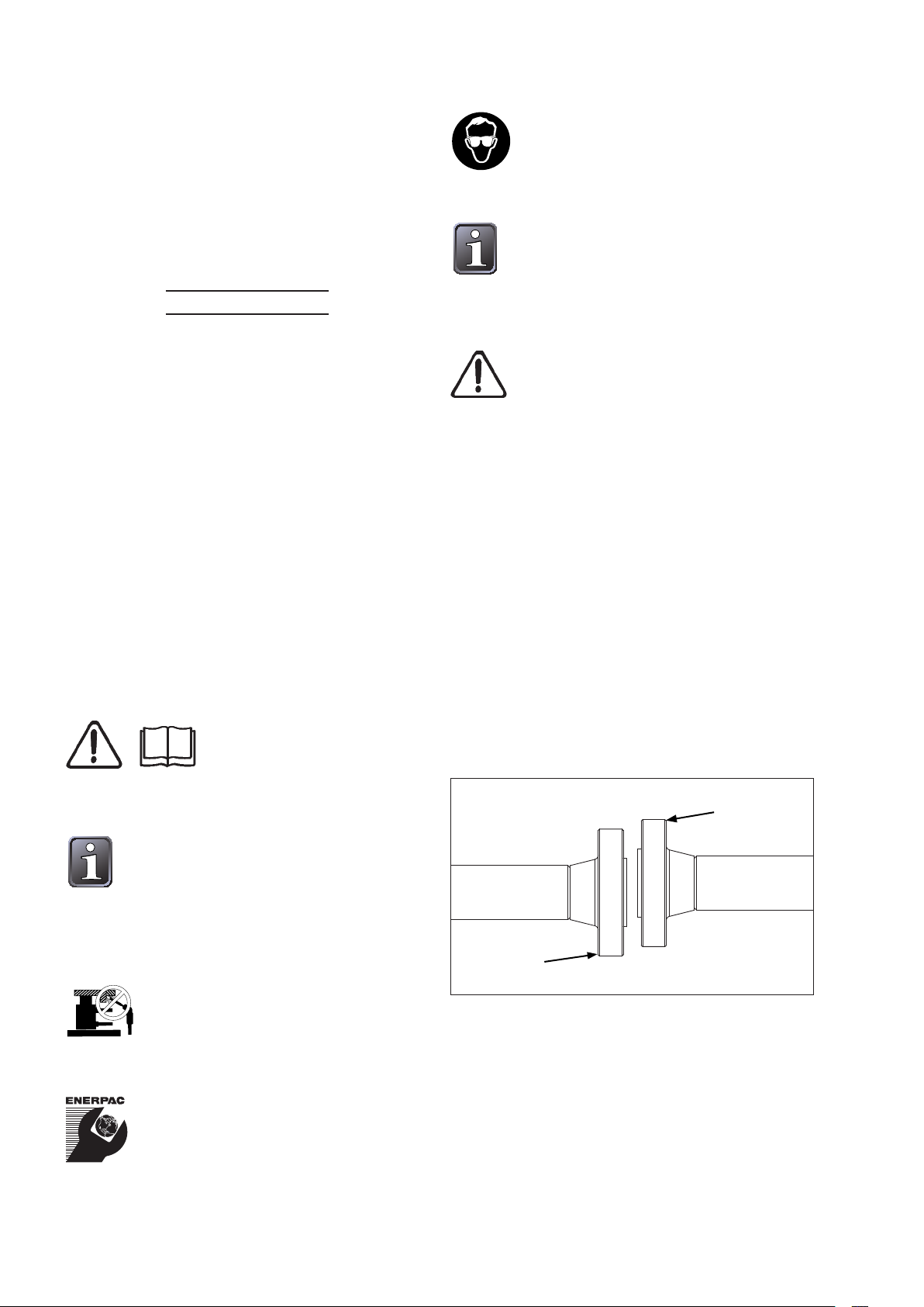
WARNING: Always wear safety glasses.
The operator must take precaution
against injury due to failure of the tool or
workpiece
We recommend the use of special
loosening liquids or sprays. Enerpac
hydraulic torque wrenches offer both
square and hexagon drive units to loosen or tighten
bolts and nuts. Enerpac offers nut splitters in case a
nut can not be removed.
WARNING: Never attach the ATM-2 to a
joint until after the flange bolts have been
loosened and removed. Overloading may
occur if bolts are removed while the tool is installed,
and the resulting force is greater than the safe
working load of the tool.
A CAUTION is used to indicate correct operating or
maintenance procedures and practices to prevent
damage to, or destruction of equipment or other
property
A WARNING indicates a potential danger that
requires correct procedures or practices to avoid
personal injury.
2.0 SAFETY ISSUES
Failure to comply with the
following cautions and warnings
could cause equipment damage
and personal injury.
IMPORTANT: Minimum age of the
operator must be 18 years. The operator
must have read and understood all
instructions, safety issues, cautions and warnings
before starting to operate the Enerpac equipment.
The operator is responsible for this activity towards
other persons.
CAUTION: Make sure that all system
components are protected from external
sources of damage, such as excessive
heat, flame, moving machine parts, sharp edges and
corrosive chemicals.
WARNING: Immediately replace worn or
damaged parts with genuine Enerpac
parts. Enerpac parts are designed to fit
properly and withstand rated loads.
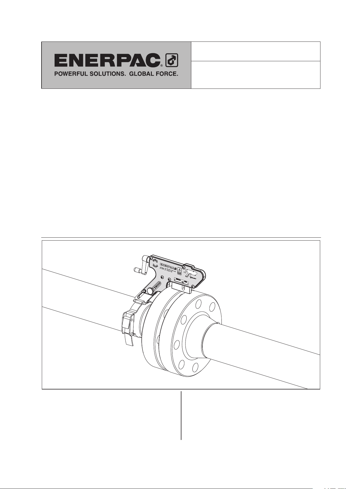
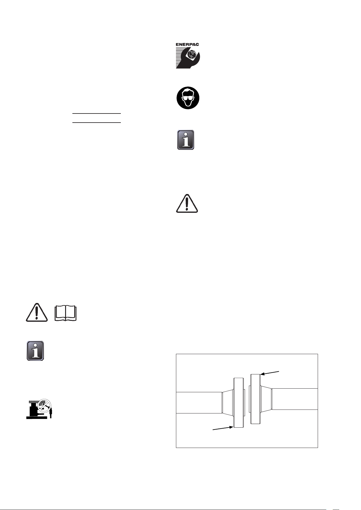
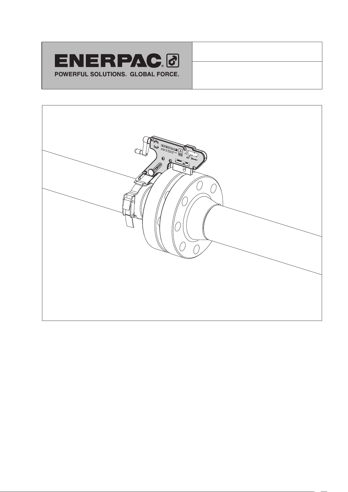
3.0 PRODUCT DESCRIPTION
The ATM-2 Alignment Tool has been developed as
the simple solution to small, low-pressure flange
misalignment.
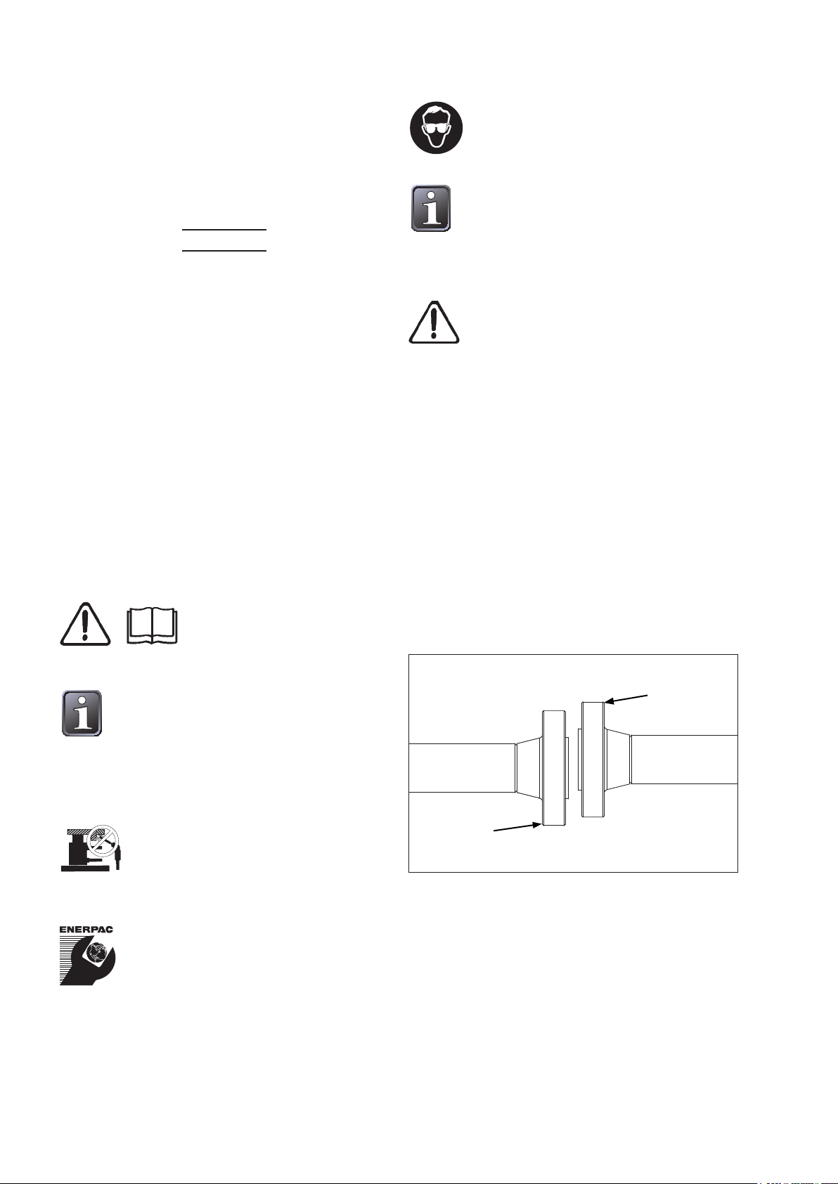
Misalignment of flange joints often occurs when they
are broken-down for testing, routine maintenance, or
during shutdowns. Also during a construction phase
when new pipe is being installed, final alignment may
be required. Current methods of flange manipulation
tend to be dangerous involving a high degree of
manual lifting and can damage the bolt holes.
Fig. 1 A Misaligned Flange Joint
POINT OF MAX.
MISALIGNMENT
POINT OF MAX.
MISALIGNMENT
The Enerpac ATM-2 Alignment Tool has been
designed as the simple solution. It is:
• Safe
• Easy to use
• Will not cause damage
• Capable of supplying a 1 ton [10 kN] load
• Can be used on many popular flange sizes
2
Page 3
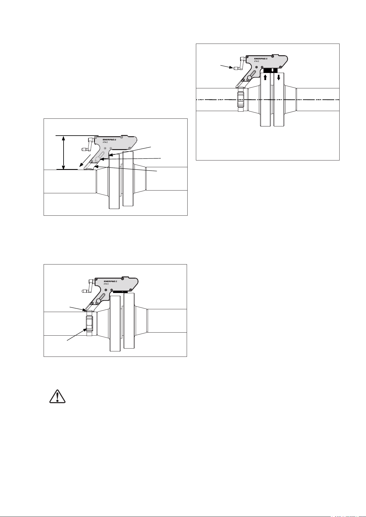
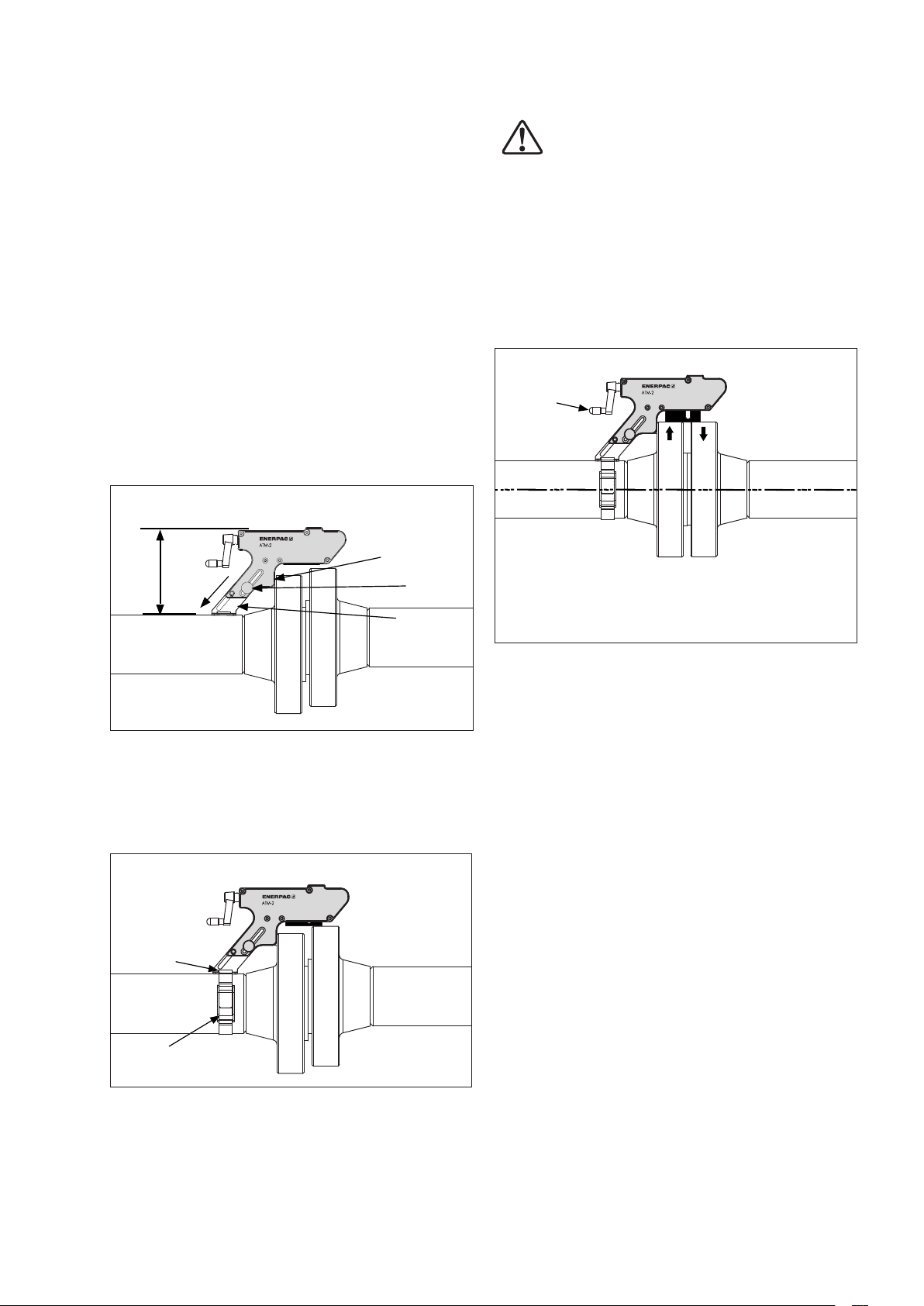
4.0 OPERATING INSTRUCTIONS
Fig. 4 Alignment
1. Determine the maximum point of misalignment.
2. Guide the lift hook of the tool into the bolt hole
at the maximum point of misalignment. The drop
leg should be released and lowered onto the pipe
while the hook is held level in the bolt hole. It then
must be secured in position by tightening the
thumb screw. See Fig.2.
Fig. 2 Assembly of Tool on Flange
LIFT
HOOK
PARALLEL
THUMB
SCREW
DROP
LEG
3. Rotate the screw handle clockwise until the driven
wedge makes contact with the opposite flange.
Thread the strap through the aperture on the base
of the drop leg, feed the end of the strap through
the buckle, and close the clasp.
Fig. 3 Strap Installation
STRAP
APERTURE
See Fig. 3.
HAND
CRANK
Maximum Recommended handle-
force = 45 lbf. [200 N].
OPERATE HANDLE BY HAND
ONLY - DO NOT USE TOOLS!
6. After removing the tool from the flange, install the
last flange bolt in the remaining bolt hole.
5.0 EXAMINATION - MAINTENANCE
• After finishing the job and before the tool is placed
back into service, the completeness of the ATM-2
tool must be established and items examined to
ensure that they are serviceable.
• Any missing or damaged items are to be replaced
as soon as possible and prior to the tool being
used again.
• Grease all moving parts regularly with Mobilgrease
XHP ™ 222 Special grease. Refer to Section 6.0.
• Return all items to the carrying case when not in
use.
6.0 INSPECTION AND LUBRICATION
STRAP
4. Rotate the screw handle clockwise until alignment
is achieved. See Fig. 4.
WARNING: Do not exceed 45 lbf. [200 N]
hand pressure on the screw handle.
Handle may break if greater force is
exerted. Never use tools to turn the handle.
5. When alignment is completed, the flange bolts
may be inserted and tightened. After replacing all
of the bolts in all open bolt holes (except for the
bolt hole in which the tool lift hook is inserted),
remove the tool by reversing steps 1 through 4.
(See Fig. 5 on next page)
STEP 1. Place tool flat on work bench.
STEP 2. Using a small, flat screwdriver, remove
circlip. Then, remove five 4mm hex screws.
STEP 3. Remove cover plate and remove any dirt
or corrosion from moving parts.
STEP 4. Inspect components for wear and damage.
Replace as required. If no damage is
present, then grease and reassemble
parts by reversing steps 1 through 4.
Note: Use Mobilgrease XHP ™ 222 Special grease
or an equivalent good quality high load bearing
grease.
3
Page 4
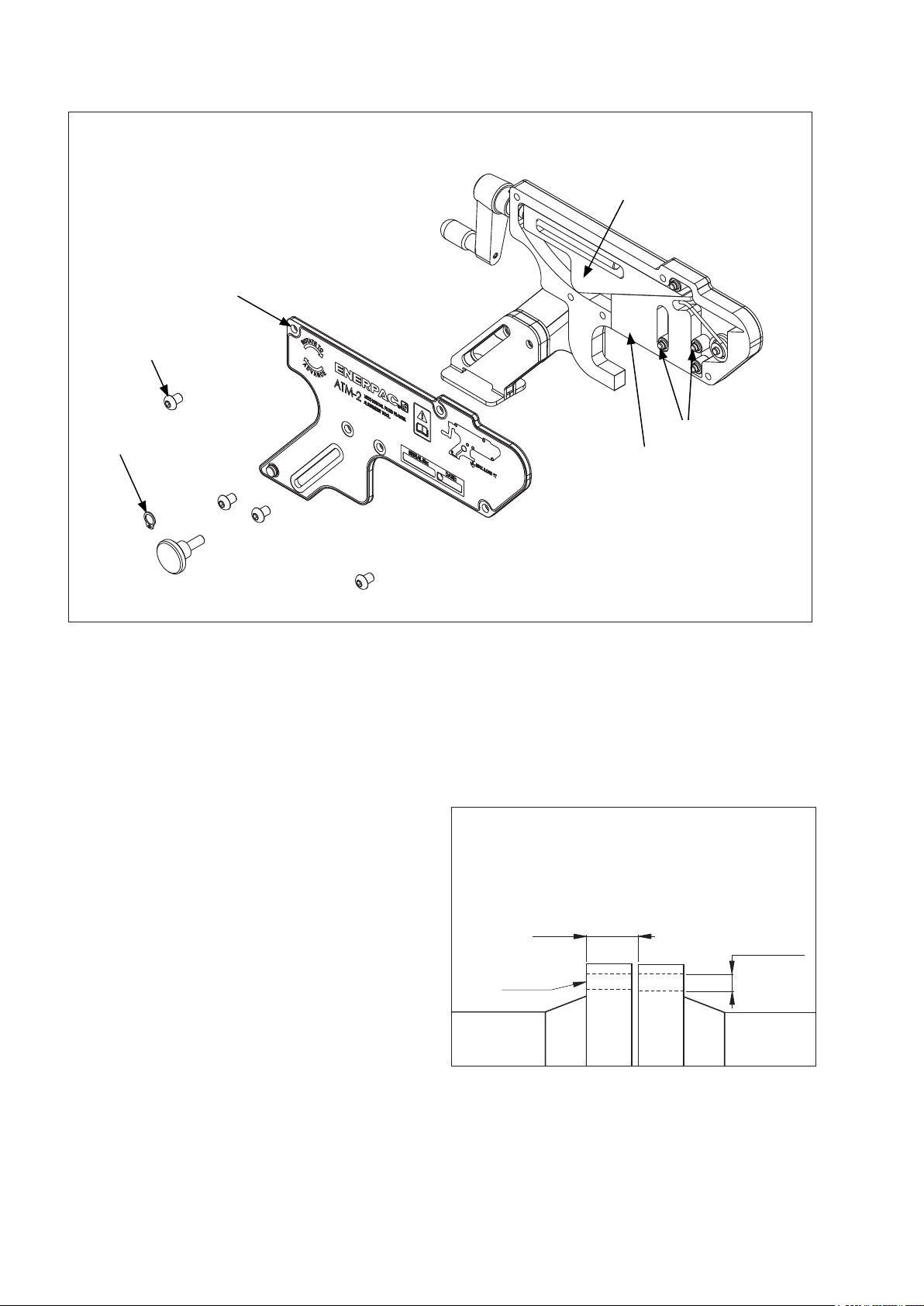
Fig. 5 Inspection and Lubrication
COVER PLATE
HEX SCREW
CIRCLIP
DRIVING WEDGE
NEEDLE
DRIVEN
WEDGE
BEARINGS
7.0 TROUBLESHOOTING
PROBLEM: THE TOOL IS ATTACHED AND
APPEARS TO BE FUNCTIONING
PROPERLY, BUT THE JOINT WILL
NOT ALIGN.
CAUSE: Hidden obstruction on the joint or
surrounding pipe or the load required
to align the joint is greater than that of
the ATM-2 (i.e. 1 Ton [10 kN] ).
SOLUTION: a. Check the area around the joint for
obstructions.
b. It may be that the required pressure
to align the joint is greater that the
1 ton [10 kN] capacity of the tool.
In this instance another method to
align the joint should be adopted.
8.0 STORAGE
• The ATM-2 should be stored in a cool dry place.
• Machined surfaces are to be smeared with
Mobilgrease XHP ™ 222 Special grease or an
equivalent good quality high load bearing grease.
9.0 APPLICATION DIMENSIONS
Fig 6 Min. and max. flange sizes (visual)
Min. distance 0.55 inch [14 mm]
Max. distance 3.23 inch [82 mm]
Hook into this
bolt hole
Min. bolt hole size
0.63 inch [16 mm]
4
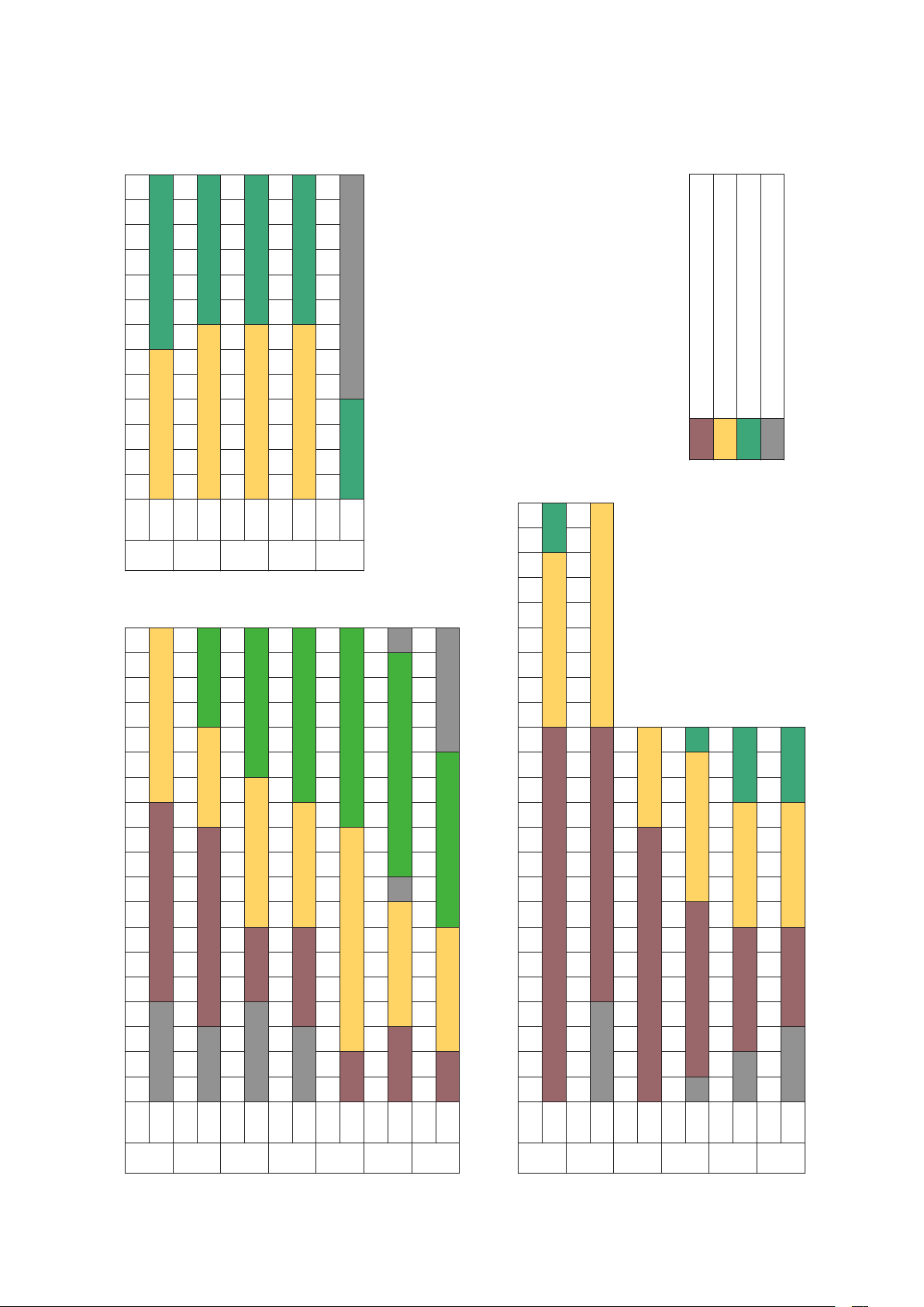
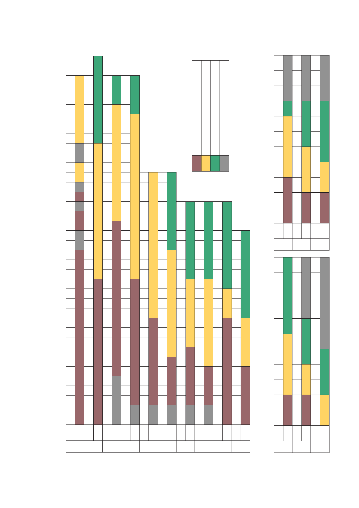
Page 5

ATM-4 ATM-4
ATM-2
SUITABLE FOR ENERPAC ATM-2 TOOL
SUITABLE FOR ENERPAC ATM-4 TOOL
SUITABLE FOR ENERPAC ATM-9 TOOL
NOT SUITABLE FOR ANY ENERPAC ATM TOOL
Note: Models ATM-4 and ATM-9 shown for reference purposes only.
3K
TOOL ATM-2 ATM-4 ATM-9
CLASS
NPS 2 1-16" 2 9-16" 3 1-8" 4 1-16" 5 1-8" 7 1-16" 9" 11" 13 5-8" 16 3-4" 21 1-4"
6K
TOOL ATM-2 ATM-4 ATM-9
CLASS
NPS 2 1-16" 2 9-16" 3 1-8" 4 1-16" 5 1-8" 7 1-16" 9" 11" 13 5-8" 16 3-4" 21 1-4"
5" 6" 7" 8" 9" 10" 11" 12" 13" 14" 15" 16"
4
4"
3
4" 5" 6" 7" 8" 9" 10" 12" 13" 14" 15" 16" 17" 18" 19" 20"
4" 5" 6" 7" 8" 9" 10" 12" 13" 14" 15" 16" 17" 18" 19" 20" 21" 22" 23" 24" 27" 29" 30" 33" 35" 36" 39" 42" 45" 48"
3
3"
2
2"
4" 5" 6" 7" 8" 9" 10" 12" 13" 14" 15" 16" 17" 18" 19" 20" 21" 22" 23" 24" 26" 27" 29" 30" 33" 35" 36" 39" 42" 45" 48" 54" 60" 66" 72"
3
1/2"
1
1
1/2"
1/2"
1/2"
1/4"
4" 5" 6" 7" 8" 9" 10" 12" 13" 14" 15" 16" 17" 18" 19" 20" 21" 22" 23" 24" 27" 29" 30" 33" 35" 36" 39" 42" 45" 48"
3
3"
2
2"
1
1
1/2"
1/2"
1/2"
1/4"
4" 5" 6" 7" 8" 9" 10" 12" 13" 14" 15" 16" 17" 18" 19" 20" 21" 22" 23" 24"
3
2
1
1
3
1/2"
3"
2
1/2"
2"
1
1/2"
1
1/4"
4" 5" 6" 7" 8" 9" 10" 12" 13" 14" 15" 16" 17" 18" 19" 20" 21" 22" 23" 24"
3"
2"
1/2"
1/2"
1/2"
1/4"
3
3"
2
2"
1
1
1/2"
1/2"
1/2"
1/4"
4" 5" 6" 7" 8" 9" 10" 12" 13" 14" 15" 16" 17" 18" 19" 20"
3
3"
2
2"
1
1
1/2"
1/2"
1/2"
1/4"
3"
2
2"
1
1
1/2"
1/2"
1/2"
1/2"
1/4"
5" 6" 7" 8" 9" 10" 11" 12" 13"
4
1/2"
4"
3
1/2"
3"
2
1/2"
2"
1
1/2"
1
1/4"
2K
TOOL ATM-2 ATM-4 ATM-9
CLASS
NPS 2 1-16" 2 9-16" 3 1-8" 4 1-16" 5 1-8" 7 1-16" 9" 11" 13 5-8" 16 3-4" 21 1-4"
NPS
BS10 Flange Range of Application
10.1
10.0 RANGE OF APPLICATION TABLES
TOOL ATM-2 ATM-2
CLASS A
NPS 4" 5" 6" 7" 8" 9" 10" 12" 13" 14" 15" 16" 17" 18" 19" 20" 21" 22" 23" 24" 29" 30" 33" 35" 36" 39" 42" 45" 48" 54" 60" 66" 72" 78" 84" 96" 108" 120"
TOOL ATM-2 ATM-4 ATM-9
CLASS D
NPS
TOOL ATM-2 ATM-4 ATM-9
CLASS E
NPS
TOOL ATM-2 ATM-4 ATM-9
CLASS F
NPS
TOOL ATM-2 ATM-4
CLASS H
NPS
TOOL ATM-2 ATM-4 ATM-9
CLASS J
NPS 1"
NPS 1"
TOOL ATM-2 ATM-4 ATM-9
CLASS K
TOOL ATM-2 ATM-4 ATM-9
CLASS R
NPS 1/2" 3/4" 1"
TOOL ATM-2 ATM-4 ATM-9
CLASS S
NPS 1/2" 3/4" 1"
TOOL ATM-2 ATM-4 ATM-9
CLASS T
NPS 1 13-16" 2 1-16" 2 9-16" 3 1-8" 4 1-16" 5 1-8" 7 1-16" 9" 11" 13 5-8" 16 3-4"
API6BX Weld Neck Flange Range of Application API6B Weld Neck Flange Range of Application
10.2 10.3
2K
TOOL ATM-2 ATM-4 ATM-9
CLASS
NPS 1 13-16" 2 1-16" 2 9-16" 3 1-8" 4 1-16" 5 1-8" 7 1-16" 9" 11" 13 5-8" 16 3-4"
3K
TOOL ATM-2 ATM-4 ATM-9
CLASS
NPS 1 13-16" 2 1-16" 2 9-16" 3 1-8" 4 1-16" 5 1-8" 7 1-16" 9" 11" 13 5-8" 16 3-4"
6K
TOOL ATM-4 ATM-9
CLASS
5
Page 6

SUITABLE FOR ENERPAC ATM-2 TOOL
SUITABLE FOR ENERPAC ATM-4 TOOL
SUITABLE FOR ENERPAC ATM-9 TOOL
NOT SUITABLE FOR ANY ENERPAC ATM TOOL
Note: Models ATM-4 and ATM-9 shown for reference purposes only.
NPS 22" 26" 28" 30" 32" 34" 36" 38" 40" 42" 44" 46" 48"
ASME B16.47 Flange Range of Application
4" 5" 6" 8" 10" 12" 14" 16" 18" 20" 24"
3
3"
2
2"
1
1
1/2"
1/2"
1/2"
1/4"
TOOL ATM-4 ATM-9
150
CLASS
NPS 22" 26" 28" 30" 32" 34" 36" 38" 40" 42" 44" 46" 48"
4" 5" 6" 8" 10" 12" 14" 16" 18" 20" 24"
3
3"
2
2"
1
1
1/2"
1/2"
1/2"
1/4"
TOOL ATM-4 ATM-9
300
CLASS
NPS 22" 26" 28" 30" 32" 34" 36" 38" 40" 42" 44" 46" 48"
4" 5" 6" 8" 10" 12" 14" 16" 18" 20" 24"
3
3"
2
2"
1
1
1/2"
1/2"
1/2"
1/4"
TOOL ATM-4 ATM-9
400
CLASS
NPS 22" 26" 28" 30" 32" 34" 36" 38" 40" 42" 44" 46" 48"
4" 5" 6" 8" 10" 12" 14" 16" 18" 20" 24"
3
3"
2
2"
1
1
1/2"
1/2"
1/2"
1/4"
TOOL ATM-4 ATM-9
600
CLASS
NPS 22" 26" 28" 30" 32" 34" 36" 38" 40" 42" 44" 46" 48"
TOOL ATM-9
900
CLASS
3" 4" 5" 6" 8" 10" 12" 14" 16" 18" 20" 24"
2
2"
1
1
1/2"
1/2"
1/4"
3" 4" 5" 6" 8" 10" 12" 14" 16" 18" 20" 24"
2
2"
1
1
1/2"
1/2"
1/4"
3" 4" 5" 6" 8" 10" 12" 14" 16" 18" 20" 24"
2
1/2"
2"
1
1/2"
1
1/4"
9
ATM-
3" 4" 5" 6" 7" 8" 10" 12" 14" 16" 18" 20" 24" 28" 32" 36" 40"
2
1/2"
2"
1
1/2"
1
3" 4" 5" 6" 7" 8" 10" 12" 14" 16" 18" 20" 24" 28" 32" 36" 40" 48" 56 72" 80"
2
1/2"
2"
1
1/2"
1/4"
3" 4" 5" 6" 7" 8" 10" 12" 14" 16" 18" 20"
2
2"
1
1/2"
1/2"
3" 4" 5" 6" 7" 8" 10" 12" 14" 16"
2
2"
1
1/2"
1/2"
3" 4" 5" 6" 7" 8" 10" 12" 14"
2
2"
1
1/2"
1/2"
3" 4" 5" 6" 7" 8" 10" 12"
2
1/2"
2"
1
1/2"
NPS 3/4" 1"
ASME B16.5 Flange Range of Application
10.4 10.6
10.0 RANGE OF APPLICATION TABLES (Continued)
TOOL ATM-2 ATM-4
150
CLASS
NPS 3/4" 1"
TOOL ATM-2 ATM-4 ATM-9
300
CLASS
NPS 3/4" 1"
TOOL ATM-2 ATM-4 ATM-9
400
CLASS
NPS 3/4" 1"
TOOL ATM-2 ATM-4 ATM-9
600
CLASS
NPS 1/2" 3/4" 1"
TOOL ATM-2 ATM-4 ATM-9
900
CLASS
NPS 1/2" 3/4" 1"
TOOL ATM-2 ATM-4 ATM-9
1500
CLASS
NPS 1/2" 3/4" 1"
TOOL ATM-2 ATM-4 ATM-9
2500
CLASS
6
NPS
DIN Weld Neck Flange Range of Application
10.5
TOOL ATM-2 ATM-4 ATM-9
PN16
CLASS
NPS 1/2" 3/4" 1"
TOOL ATM-2 ATM-4
PN25
CLASS
NPS
TOOL ATM-2 ATM-4
PN40
CLASS
NPS 3/4" 1"
TOOL ATM-2 ATM-4
PN54
CLASS
NPS 1/2" 3/4" 1"
TOOL ATM-2 ATM-4 ATM-9
PN100
CLASS
NPS 3/8" 1/2" 3/4" 1"
TOOL ATM-2 ATM-4 ATM-9
PN160
CLASS
Page 7

SUITABLE FOR ENERPAC ATM-2 TOOL
SUITABLE FOR ENERPAC ATM-4 TOOL
SUITABLE FOR ENERPAC ATM-9 TOOL
NOT SUITABLE FOR ANY ENERPAC ATM TOOL
Note: Models ATM-4 and ATM-9 shown for reference purposes only.
4" 5" 6" 8" 10" 12" 14" 16" 18" 20" 22" 24" 26" 28" 30" 32" 34" 36" 38" 40" 42" 44" 46" 48"
3
3"
2
TOOL\NPS
10.7
SPO Flange Range of Application
1/2"
1/2"
TOOL ATM-2 ATM-4
150
CLASS
4" 5" 6" 8" 10" 12" 14" 16" 18" 20" 22" 24" 26" 28" 30" 32" 34" 36" 38" 40" 42" 44" 46" 48"
3
1/2"
3"
2
1/2"
TOOL\NPS
300
TOOL ATM-2 ATM-4 ATM-9
CLASS
4" 5" 6" 8" 10" 12" 14" 16" 18" 20" 22" 24" 26" 28" 30" 32" 34" 36" 38" 40" 42" 44" 46" 48"
3
1/2"
3"
2
1/2"
TOOL\NPS
600
TOOL ATM-4 ATM-9
CLASS
4" 5" 6" 8" 10" 12" 14" 16" 18" 20" 22" 24" 26" 28" 30" 32" 34" 36" 38" 40" 42" 44" 46" 48"
3
1/2"
3"
2
1/2"
TOOL\NPS
900
TOOL ATM-4 ATM-9
CLASS
4" 5" 6" 8" 10" 12" 14" 16" 18" 20" 22" 24" 26" 28" 30" 32" 34" 36" 38" 40" 42" 44" 46" 48"
3
1/2"
3"
2
1/2"
TOOL\NPS
TOOL ATM-4 ATM-9
1500
CLASS
10.0 RANGE OF APPLICATION TABLES (Continued)
7
4" 5" 6" 8" 10" 12" 14" 16" 18" 20" 22" 24"
3
1/2"
3"
2
1/2"
TOOL\NPS
TOOL ATM-4 ATM-9
2500
CLASS
4" 5" 6" 8" 10" 12" 14" 16" 18" 20" 22" 24"
3
1/2"
3"
2
1/2"
TOOL\NPS
5000
TOOL ATM-4 ATM-9
CLASS
4" 5" 6" 8" 10" 12" 14" 16" 18" 20" 22" 24"
3
1/2"
3"
2
1/2"
TOOL\NPS
7500
TOOL ATM-4 ATM-9
CLASS
4" 5" 6" 8" 10" 12" 14" 16" 18" 20" 22" 24"
3
1/2"
3"
2
1/2"
TOOL\NPS
TOOL ATM-4 ATM-9
10000
CLASS
4" 5" 6" 8" 10" 12" 14" 16" 18" 20" 22" 24"
3
1/2"
3"
2
1/2"
TOOL\NPS
TOOL ATM-4 ATM-9
15000
CLASS
Page 8
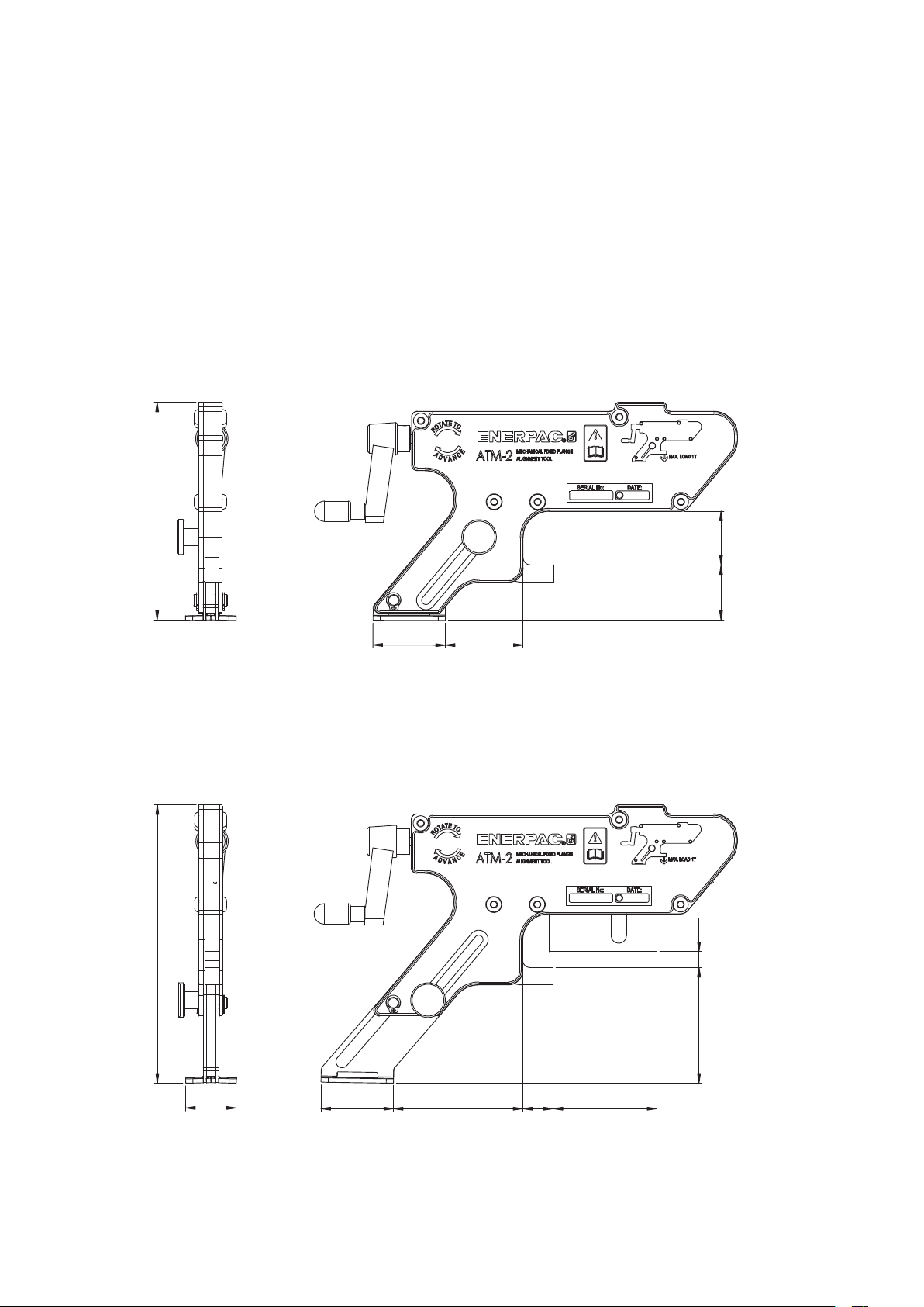
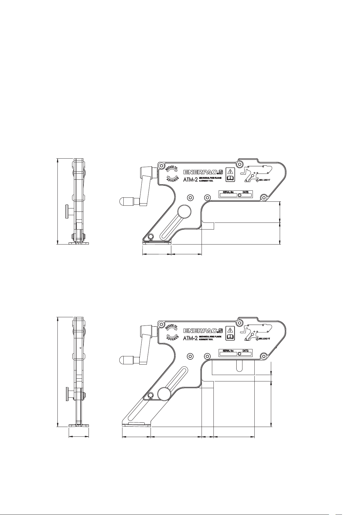
11.0 WEIGHTS AND DIMENSIONS
WEIGHTS
Note: Weights shown are approximate.
Tool, ratchet and strap ........................................................ 4.4 lbs [2,0 kg]
Box, packing and instruction manual ............................................ 0.9 lbs [0,4 kg]
DIMENSIONS
Minimum Extension
5.94"
[151 mm]
1.46"
[37 mm]
1.50"
[38 mm]
1.46"
[37 mm]
1.99"
[50 mm]
2.13"
[54 mm]
Maximum Extension
0.43"
[11 mm]
3.23"
[82 mm]
1.38"
[35 mm]
1.99"
[50 mm]
3.58"
[91 mm]
8
0.83"
[21 mm]
2.83"
[72 mm]
Page 9

L4060 Rév. B 02/14
Manuel d'instructions
Outil d'alignement de bride
Modèle ATM-2
Paragraphe page
1.0 Instructions pour la réception ......................................................10
2.0 Sécurité .......................................................................10
3.0 Description du produit ...........................................................10
4.0 Instructions d’utilisation ..........................................................11
5.0 Examen - Entretien .............................................................11
6.0 Inspection et lubrification .........................................................11
7.0 Dépannage ....................................................................12
8.0 Stockage ......................................................................12
9.0 Dimensions d’application .........................................................12
10.0 Tableaux des applications ...................................................... 13-15
11.0 Tailles et poids .................................................................16
99
Page 10
1.0 INSTRUCTIONS POUR LA RÉCEPTION
A la réception du matériel, veuillez contrôler qu’aucun
composant n’a été endommagé par le transport. Ces
dommages ne sont pas couverts par la garantie. En cas
formes et supportent les charges préconisées.
de dommages liés au transport, veuillez directement en
informer le transporteur. Celui-ci est tenu de prendre en
charge tous les frais de réparation et de remplacement
résultant des dommages occasionnés lors du transport.
sécurité d’abord
défaut de l’outil ou de la pièce de travail.
AVERTISSEMENT : Remplacez immédiatement tous les éléments usés ou endommagés
par des pièces d’origine Enerpac. Les pièces
d’origine Enerpac sont parfaitement con-
AVERTISSEMENT : Portez toujours des
lunettes de sécurité. L’opérateur doit toujours
prendre des précautions contre les risques
de dommages corporels encourus en cas de
Veuillez lire attentivement toutes les instructions et
avertissements. Suivez toutes les recommandations pour
la sécurité afin d’éviter les blessures ou la détérioration
d’objets pendant l’utilisation du système. Enerpac ne peut
être tenu pour responsable des dommages et blessures
qui résultent d’une utilisation dangereuse, d’un manque
de maintenance ou d’un maniement incorrect du produit
et/ou du système. En cas de doute concernant les
hydrauliques Enerpac disposent aussi bien d’une unité
d’entraînement carrée que d’une unité hexagonale pour
desserrer ou resserrer les boulons et les écrous. Enerpac
fournit des casses-écrous dans le cas où un écrou ne
pourrait pas être démonté.
précautions et les mesures de sécurité, n’hésitez pas à
contacter Enerpac.
La mention PRECAUTION indique les procédures de
mise en fonctionnement et d’entretien à suivre ainsi que
les opérations à effectuer afin d’éviter tout dommage ou
toute entrave au fonctionnement de l’équipement ou d’un
produire si vous retirez les boulons alors que l'outil est
installé, et la force en résultant dépasse la charge
admissible sans danger par l'outil.
autre matériel.
3.0 DESCRIPTION DU PRODUIT
La mention AVERTISSEMENT signale un danger potentiel.
Veuillez suivre les procédures adéquates ou effectuer
les opérations nécessaires afin d’éviter tout dommage
corporel.
2.0 SÉCURITÉ
L'outil d'alignement ATM-2 a été conçu comme la solution
la plus simple à un petit désalignement de bride basse
pression.
Souvent, les brides sont désalignés lors de leur démontage
en vue d'un test, d'une maintenance de routine ou lors d'un
Ne pas tenir compte des mentions
PRÉCAUTION et AVERTISSEMENT
ci-après peut mener à la
détérioration de l’équipement et être source de blessures.
arrêt. De même, pendant la phase de construction, lors de
la pose d'un nouveau tuyau, il peut être nécessaire de
procéder à un alignement final. Les méthodes actuelles de
manipulation de bride présentent des risques potentiels.
Elles impliquent de nombreuses manœuvres manuelles et
IMPORTANT : L’opérateur doit être âgé d’au
peuvent endommager les passages de boulon.
moins dix-huit ans. Il doit avoir lu et compris
toutes les instructions, les données pour la
Fig. 1 Désalignement de brides
sécurité, les mentions PRECAUTION et AVERTISSEMENT
avant de commencer à travailler avec un équipement
Enerpac. L’opérateur est responsable des conséquences
que son travail pourrait avoir pour d’autres personnes.
Nous vous recommandons d’utiliser les liquides
ou les vaporisateurs spécialement conçus pour
le desserrage. Les clés dynamométriques
AVERTISSEMENT: Attendez toujours d'avoir
dévissé et retiré les boulons de bride avant de
fixer l'ATM-2 à un joint. Une surcharge peut se
POINT DE
DÉSALIGNEMENT
MAXIMAL
PRÉCAUTION : Tous les composants du
système doivent être protégés contre tout
dommage pouvant être occasionné par des
sources externes comme la chaleur excessive, le feu, les
pièces mobiles d’une machine, les bords pointus et les
produits chimiques corrosifs.
POINT DE
DÉSALIGNEMENT
MAXIMAL
1010
Page 11
L'outil d'alignement Enerpac ATM-2 a été conçu pour
simplifier les opérations. Il est:
• Sans danger
• Simple à utiliser
elle est soumise à une force supérieure. Ne jamais utiliser
d'outil pour faire tourner l'ailette.
• Ne cause aucun dégât
• Capable de fournir une charge d'une tonne [10 kN]
5. Lorsque l'alignement est terminé, vous pouvez
• Utilisable sur de nombreuses tailles de bride très
répandues
4.0 INSTRUCTIONS D'UTILISATION
1. Déterminer le point de désalignement maximal.
Fig. 4 Alignement
2. Guider le crochet de levage de l'outil dans le passage
du boulon au point de désalignement maximal. La
MANIVELLE
jambe support doit être dégagée et abaissée sur le
tuyau alors que le crochet est maintenu de niveau dans
le passage du boulon. Vous devez ensuite la fixer en
position en serrant la vis moletée. Voir fig.2.
Fig. 2 Montage d'outil sur bride
CROCHET
DE LEVAGE
VIS
PARALLÈLE
MOLETÉE
JAMBE
SUPPORT
AVERTISSEMENT : Ne pas dépasser une
pression manuelle de 200 N [45 lbf.] sur
l'ailette de la vis. L´ailette risque de casser si
introduire et serrer les boulons de bride. Après avoir
remplacé tous les boulons dans tous les passages (à
l'exception de celui où se trouve le crochet de levage
de l'outil), retirer l'outil en suivant les étapes 1 à 4, en
sens inverse.
Force de manipulation maximale recommandée
= 200 N [45 livre-force].
MANIPULATION MANUELLE DE LA MANETTE
UNIQUEMENT - UTILISATION D'OUTIL INTERDITE !
6. Après avoir retiré l'outil de la bride, poser le dernier
3. Tourner l'ailette de la vis dans le sens horaire jusqu'à
5.0 EXAMEN - ENTRETIEN
ce que le coin entraîné touche la bride opposée. Faire
passer la sangle par l'ouverture qui se trouve à la base
• Une fois la tâche terminée et avant de remettre l'outil
de la jambe support, faire passer l'extrémité de la
sangle dans la boucle et actionner le fermoir. Voir fig.3.
Fig. 3 Pose de sangle
• Tout élément manquant ou endommagé doit être
• Graisser régulièrement toutes les pièces avec de la
PASSAGE
DE
SANGLE
• Remettre tous les éléments non utilisés dans le coffret
6.0 INSPECTION ET LUBRIFICATION
SANGLE
(Voir fig. 5 à la page suivante)
ÉTAPE 1: Poser l´outil à plat sur l'établi.
4. Tourner l'ailette de la vis dans le sens horaire jusqu'à
alignement complet. Voir fig.4.
ÉTAPE 2: À l'aide d'un petit tournevis plat, retirer l'anneau
boulon de bride dans le passage restant.
en service, vérifier que l'outil ATM-2 est complet et
examiner les éléments pour s'assurer qu'ils sont aptes
au service.
remplacé le plus rapidement possible avant d'utiliser à
nouveau l'outil.
graisse Mobilgrease XHP ™ 222 Special. Voir la section
6.0.
de rangement.
élastique. Ensuite, retirer les cinq vis à tête
1111
Page 12

Fig. 5 Inspection et lubrification
COUVERCLE
VIS À TÊTE HEXAGONALE
ANNEAU ÉLASTIQUE
COIN D'ENTRAÎNEMENT
ROULEMENTS
COIN
ENTRAÎNÉ
À AIGUILLES
hexagonale de 4 mm.
ÉTAPE 3: Retirer le capot et éliminer toute saleté ou
b. Il se peut que la pression requise pour
corrosion des pièces mobiles.
ÉTAPE 4: Inspecter les composants pour identifier toute
usure ou tout endommagement. Procéder
à tout remplacement requis. En l'absence
d'endommagement, graisser et remonter les
8.0 STOCKAGE
pièces dans l'ordre inverse des étapes 1 à 4.
• L'ATM-2 doit être stocké au sec et à l'abri de la chaleur.
Remarque : Utiliser de la graisse Mobilgrease XHP ™
• Lubrifier les surfaces usinées avec de la graisse
222 Special ou toute autre graisse équivalente de bonne
qualité pour utilisation intensive.
7.0 DÉPANNAGE
PROBLÈME : L'OUTIL EST FIXÉ ET SEMBLE
9.0 DIMENSIONS D'APPLICATION
Fig 6 Tailles min. & max. de bride (visuel)
FONCTIONNER CORRECTEMENT MAIS
LE JOINT NE S'ALIGNE PAS.
CAUSE : Un obstacle non visible sur le joint ou
le tuyau à proximité, ou bien la charge
requise pour aligner le joint est supérieure
à celle fournie par l'ATM-2 (par ex. 1 T. [10
kN]).
aligner le joint soit supérieure à la
capacité de 1 tonne [10 kN] de l'outil.
Dans ce cas, il convient d'adopter une
autre méthode pour aligner le joint.
Mobilgrease XHP ™ 222 Special ou toute autre graisse
équivalente de bonne qualité pour utilisation intensive.
Distance min. 14 mm [0,55 pouces]
Distance max. 82 mm [3,23 pouces]
Passer le crochet
dans ce passage
de boulon
Taille min. de passage
de boulon
16 mm [0,63 pouce]
SOLUTION : a. Vérifier s'il y a des obstacles dans la
zone autour du joint.
1212
Page 13

ATM-4 ATM-4
ATM-2
CONVIENT À L'OUTIL ENERPAC ATM-2
CONVIENT À L'OUTIL ENERPAC ATM-4
CONVIENT À L'OUTIL ENERPAC ATM-9
NE CONVIENT À AUCUN OUTIL ENERPAC ATM
Remarque : Les modèles ATM-4 et ATM-9 sont montrés
uniquement à titre de référence.
la bride
3K
Outil ATM-2 ATM-4 ATM-9
Catégorie
2 1-16" 2 9-16" 3 1-8" 4 1-16" 5 1-8" 7 1-16" 9" 11" 13 5-8" 16 3-4" 21 1-4"
Diamètre
intérieur de
1 13-16" 2 1-16" 2 9-16" 3 1-8" 4 1-16" 5 1-8" 7 1-16" 9" 11" 13 5-8" 16 3-4"
la bride
6K
Outil ATM-2 ATM-4 ATM-9
Catégorie
2 1-16" 2 9-16" 3 1-8" 4 1-16" 5 1-8" 7 1-16" 9" 11" 13 5-8" 16 3-4" 21 1-4"
Diamètre
intérieur de
5" 6" 7" 8" 9" 10" 11" 12" 13" 14" 15" 16"
4
4"
3
4" 5" 6" 7" 8" 9" 10" 12" 13" 14" 15" 16" 17" 18" 19" 20"
4" 5" 6" 7" 8" 9" 10" 12" 13" 14" 15" 16" 17" 18" 19" 20" 21" 22" 23" 24" 27" 29" 30" 33" 35" 36" 39" 42" 45" 48"
3
3"
2
2"
4" 5" 6" 7" 8" 9" 10" 12" 13" 14" 15" 16" 17" 18" 19" 20" 21" 22" 23" 24" 29" 30" 33" 35" 36" 39" 42" 45" 48" 54" 60" 66" 72" 78" 84" 96" 108" 120"
1
1
4" 5" 6" 7" 8" 9" 10" 12" 13" 14" 15" 16" 17" 18" 19" 20" 21" 22" 23" 24" 26" 27" 29" 30" 33" 35" 36" 39" 42" 45" 48" 54" 60" 66" 72"
3
1/2"
1/2"
1/2"
1/2"
1/4"
4" 5" 6" 7" 8" 9" 10" 12" 13" 14" 15" 16" 17" 18" 19" 20" 21" 22" 23" 24" 27" 29" 30" 33" 35" 36" 39" 42" 45" 48"
3
3"
2
2"
1
1
1/2"
1/2"
1/2"
1/4"
4" 5" 6" 7" 8" 9" 10" 12" 13" 14" 15" 16" 17" 18" 19" 20" 21" 22" 23" 24"
3
1/2"
3
3"
2
1/2"
2
2"
1
1
1/2"
1/4"
1
1
4" 5" 6" 7" 8" 9" 10" 12" 13" 14" 15" 16" 17" 18" 19" 20" 21" 22" 23" 24"
3"
2"
1/2"
1/2"
1/2"
1/4"
3
3"
2
2"
1
1
1"
1/2"
1/2"
1/2"
1/4"
4" 5" 6" 7" 8" 9" 10" 12" 13" 14" 15" 16" 17" 18" 19" 20"
3
3"
2
2"
1
1
1"
1/2"
1/2"
1/2"
1/4"
3"
2
2"
1
1
1/2" 3/4" 1"
1/2"
1/2"
1/2"
1/2"
1/4"
5" 6" 7" 8" 9" 10" 11" 12" 13"
4
1/2"
4"
3
1/2"
3"
2
1/2"
2"
1
1/2"
1
1/4"
TM-2 ATM-4 ATM-9
1/2" 3/4" 1"
1 13-16" 2 1-16" 2 9-16" 3 1-8" 4 1-16" 5 1-8" 7 1-16" 9" 11" 13 5-8" 16 3-4"
la bride
2K
Outil ATM-2 ATM-4 ATM-9
Catégorie
2 1-16" 2 9-16" 3 1-8" 4 1-16" 5 1-8" 7 1-16" 9" 11" 13 5-8" 16 3-4" 21 1-4"
Diamètre
intérieur de
1 13-16" 2 1-16" 2 9-16" 3 1-8" 4 1-16" 5 1-8" 7 1-16" 9" 11" 13 5-8" 16 3-4"
Outil ATM-2 ATM-2
la bride
Diamètre
intérieur de
A
Applications de brides BS10
10.1
10.0 TABLEAU DES APPLICATIONS
Outil ATM-2 ATM-4 ATM-9
la bride
Diamètre
intérieur de
D
Catégorie
Catégorie
Outil ATM-2 ATM-4 ATM-9
la bride
Diamètre
intérieur de
E
Catégorie
Outil ATM-2 ATM-4 ATM-9
la bride
Diamètre
Diamètre
intérieur de
intérieur de
F
Catégorie
la bride
H
Outil ATM-2 ATM-4
Catégorie
Outil ATM-2 ATM-4 ATM-9
la bride
Diamètre
intérieur de
J
Catégorie
Outil ATM-2 ATM-4 ATM-9
la bride
Diamètre
intérieur de
K
13
13
Catégorie
Outil ATM-2 ATM-4 ATM-9
la bride
Diamètre
intérieur de
R
Catégorie
Outil ATM-2 ATM-4 ATM-9
la bride
Diamètre
intérieur de
S
Catégorie
Outil A
la bride
Diamètre
intérieur de
T
Catégorie
10.2 10.3
Outil ATM-2 ATM-4 ATM-9
la bride
Diamètre
intérieur de
2K
Applications de brides à collerette API6BX Applications de brides à collerette API6B
Outil ATM-2 ATM-4 ATM-9
la bride
Diamètre
intérieur de
3K
Catégorie
Outil ATM-4 ATM-9
la bride
Diamètre
intérieur de
6K
Catégorie
Catégorie
Page 14
CONVIENT À L'OUTIL ENERPAC ATM-2
CONVIENT À L'OUTIL ENERPAC ATM-4
CONVIENT À L'OUTIL ENERPAC ATM-9
NE CONVIENT À AUCUN OUTIL ENERPAC ATM
Remarque : Les modèles ATM-4 et ATM-9 sont montrés
uniquement à titre de référence.
22" 26" 28" 30" 32" 34" 36" 38" 40" 42" 44" 46" 48"
Diamètre
intérieur de
Applications de brides ASME B16.47
4" 5" 6" 8" 10" 12" 14" 16" 18" 20" 24"
3
3"
2
2"
1
1
3/4" 1"
la bride
1/2"
1/2"
1/2"
1/4"
150
Outil ATM-4 ATM-9
Catégorie
22" 26" 28" 30" 32" 34" 36" 38" 40" 42" 44" 46" 48"
22" 26" 28" 30" 32" 34" 36" 38" 40" 42" 44" 46" 48"
Outil ATM-4 ATM-9
la bride
Diamètre
Diamètre
intérieur de
3
2
1
1
4" 5" 6" 8" 10" 12" 14" 16" 18" 20" 24"
3"
2"
3/4" 1"
1/2"
1/2"
1/2"
1/4"
300
intérieur de
Catégorie
4" 5" 6" 8" 10" 12" 14" 16" 18" 20" 24"
3
3"
2
2"
1
1
3/4" 1"
la bride
1/2"
1/2"
1/2"
1/4"
400
Outil ATM-4 ATM-9
Catégorie
22" 26" 28" 30" 32" 34" 36" 38" 40" 42" 44" 46" 48"
Diamètre
intérieur de
la bride
600
Outil ATM-4 ATM-9
Catégorie
22" 26" 28" 30" 32" 34" 36" 38" 40" 42" 44" 46" 48"
Outil ATM-9
la bride
Diamètre
intérieur de
900
Catégorie
4" 5" 6" 8" 10" 12" 14" 16" 18" 20" 24"
3
3"
2
2"
1
1
3/4" 1"
1/2"
1/2"
1/2"
1/4"
3" 4" 5" 6" 8" 10" 12" 14" 16" 18" 20" 24"
2
2"
1
1
1/2" 3/4" 1"
1/2"
1/2"
1/4"
3" 4" 5" 6" 8" 10" 12" 14" 16" 18" 20" 24"
2
1/2"
2"
1
1/2"
1
1/4"
1/2" 3/4" 1"
9
ATM-
1/2"
1/2"
3" 4" 5" 6" 7" 8" 10" 12" 14" 16" 18" 20" 24" 28" 32" 36" 40"
2
1/2"
2"
1
1/2"
1
1/4"
3" 4" 5" 6" 7" 8" 10" 12" 14" 16" 18" 20"
2
1/2"
3" 4" 5" 6" 7" 8" 10" 12" 14" 16"
2
2"
1
1/2"
1/2"
3" 4" 5" 6" 7" 8" 10" 12" 14"
2
2"
1
2"
1
1/2" 3/4" 1"
1/2"
3/4" 1"
1/2" 3/4" 1"
3" 4" 5" 6" 8" 10" 12" 14" 16" 18" 20" 24"
2
1/2"
2"
1
1/2"
1
1/4"
3" 4" 5" 6" 7" 8" 10" 12" 14" 16" 18" 20" 24" 28" 32" 36" 40" 48" 56 72" 80"
2
2"
1/2" 3/4" 1"
1
1/2"
1/2"
3" 4" 5" 6" 7" 8" 10" 12"
2
1/2"
2"
1
1/2"
3/8" 1/2" 3/4" 1"
Outil ATM-2 ATM-4
la bride
Diamètre
intérieur de
150
Applications de brides ASME B16.5
10.4 10.6
10.0 TABLEAU DES APPLICATIONS (Suite)
Outil ATM-2 ATM-4 ATM-9
la bride
Diamètre
intérieur de
300
Catégorie
Outil ATM-2 ATM-4 ATM-9
la bride
Diamètre
intérieur de
400
Catégorie
Outil ATM-2 ATM-4 ATM-9
la bride
Diamètre
intérieur de
600
Catégorie
Outil ATM-2 ATM-4 ATM-9
la bride
Diamètre
intérieur de
Catégorie
900
la bride
Diamètre
intérieur de
Catégorie
Outil ATM-2 ATM-4 ATM-9
1500
bride
Outil ATM-2 ATM-4 ATM-9
la bride
Diamètre
intérieur de
2500
Catégorie
14
14
Catégorie
Applications de brides à collerette DIN
10.5
Outil ATM-2 ATM-4 ATM-9
Diamètre
intérieur de la
PN16
Outil ATM-2 ATM-4
la bride
Diamètre
intérieur de
PN25
Catégorie
Outil ATM-2 ATM-4
la bride
Diamètre
intérieur de
PN40
Catégorie
Outil ATM-2 ATM-4
la bride
Diamètre
intérieur de
PN54
Catégorie
Outil ATM-2 ATM-4 ATM-9
la bride
Diamètre
intérieur de
PN100
Catégorie
Outil ATM-2 ATM-4 ATM-9
la bride
Diamètre
intérieur de
PN160
Catégorie
Catégorie
Page 15

CONVIENT À L'OUTIL ENERPAC ATM-2
CONVIENT À L'OUTIL ENERPAC ATM-4
CONVIENT À L'OUTIL ENERPAC ATM-9
NE CONVIENT À AUCUN OUTIL ENERPAC ATM
Remarque : Les modèles ATM-4 et ATM-9 sont montrés
uniquement à titre de référence.
4" 5" 6" 8" 10" 12" 14" 16" 18" 20" 22" 24" 26" 28" 30" 32" 34" 36" 38" 40" 42" 44" 46" 48"
3
3"
2
Diamètre intérieur
10.7
Applications de brides SPO
1/2"
1/2"
Outil ATM-2 ATM-4
de la bride
150
Catégorie
4" 5" 6" 8" 10" 12" 14" 16" 18" 20" 22" 24" 26" 28" 30" 32" 34" 36" 38" 40" 42" 44" 46" 48"
3
1/2"
3"
2
1/2"
de la bride
Diamètre intérieur
300
Outil ATM-2 ATM-4 ATM-9
Catégorie
4" 5" 6" 8" 10" 12" 14" 16" 18" 20" 22" 24" 26" 28" 30" 32" 34" 36" 38" 40" 42" 44" 46" 48"
3
1/2"
3"
2
1/2"
de la bride
Diamètre intérieur
600
Outil ATM-4 ATM-9
Catégorie
4" 5" 6" 8" 10" 12" 14" 16" 18" 20" 22" 24" 26" 28" 30" 32" 34" 36" 38" 40" 42" 44" 46" 48"
3
1/2"
3"
2
1/2"
de la bride
Diamètre intérieur
900
10.0 TABLEAU DES APPLICATIONS (Suite)
Outil ATM-4 ATM-9
Catégorie
4" 5" 6" 8" 10" 12" 14" 16" 18" 20" 22" 24" 26" 28" 30" 32" 34" 36" 38" 40" 42" 44" 46" 48"
3
1/2"
3"
2
1/2"
de la bride
Diamètre intérieur
1500
15
15
Outil ATM-4 ATM-9
Catégorie
4" 5" 6" 8" 10" 12" 14" 16" 18" 20" 22" 24"
3
1/2"
3"
2
1/2"
de la bride
Diamètre intérieur
Outil ATM-4 ATM-9
2500
Catégorie
4" 5" 6" 8" 10" 12" 14" 16" 18" 20" 22" 24"
3
1/2"
3"
2
1/2"
de la bride
Diamètre intérieur
Outil ATM-4 ATM-9
5000
Catégorie
4" 5" 6" 8" 10" 12" 14" 16" 18" 20" 22" 24"
3
1/2"
3"
2
1/2"
de la bride
Diamètre intérieur
Outil ATM-4 ATM-9
7500
4" 5" 6" 8" 10" 12" 14" 16" 18" 20" 22" 24"
3
3"
2
Diamètre intérieur
Catégorie
1/2"
1/2"
Outil ATM-4 ATM-9
de la bride
10000
4" 5" 6" 8" 10" 12" 14" 16" 18" 20" 22" 24"
3
1/2"
3"
2
1/2"
Outil ATM-4 ATM-9
de la bride
Diamètre intérieur
15000
Catégorie
Catégorie
Page 16
11.0 TAILLES ET POIDS
POIDS
Remarque : Les poids indiqués sont approximatifs.
Outil, roue à cliquet et sangle .................................................2,0 kg [4,4 livres]
Boîte, conditionnement et manuel d'utilisation ....................................0,4 kg [0,9 livres]
DIMENSIONS
Extension minimale
151 mm
[5.94"]
37 mm
[1.46"]
38 mm
[1.50"]
37 mm
[1.46"]
50 mm
[1.99"]
54 mm
[2.13"]
Extension maximal
11 mm
[0.43"]
82 mm
[3.23"]
35 mm
[1.38"]
50 mm
[1.99"]
91 mm
[3.58"]
16
16
21 mm
[0.83"]
72 mm
[2.83"]
Page 17
L4060 Rev. B 02/14
Bedienungsanleitung
Flanschausrichtungswerkzeug
Modell ATM-2
Abschnitt Seite
1.0 Beim Empfang zu beachten .......................................................18
2.0 Sicherheitsvorschriften ...........................................................18
3.0 Produktbeschreibung ............................................................18
4.0 Bedienungsanleitung .............................................................19
5.0 Prüfung - Wartung ..............................................................19
6.0 Inspektion und Schmierung .......................................................19
7.0 Fehlersuche und -behebung .......................................................20
8.0 Lagerung ......................................................................20
9.0 Anwendungsabmessungen ........................................................20
10.0 Tabellen mit den verschiedenen Anwendungsbereichen ............................... 21-23
11.0 Gewicht und Abmessungen .......................................................24
1717
Page 18

1.0 ANWEISUNGEN FÜR DEN EMPFANG
Überprüfen Sie alle Komponenten optisch auf Transportschäden, da Transportschäden nicht unter die Garantie fallen.
Sollten Sie Transportschäden feststellen, benachrichtigen
Werkstücks entstehen.
Sie bitte sofort die Speditionsfirma. Die Speditionsfirma
haftet für alle Reparatur- und Austauschkosten, die durch
transportbedingte Schäden anfallen.
sicherheit ist oberstes Gebot
Drehmoment schlüssel und Nuttensprenger. Bitte wenden
Sie sich an Enerpac oder Ihren entsprechenden
Lesen Sie alle Anweisungen, Warnungen und Vorsichts-
Stützpunkthändler.
maßnahmen sorgfältig durch. Befolgen Sie sämtliche
Sicherheitsvorschriften, um Personen- oder Sachschäden
während des Betriebs des Systems zu verhindern. Enerpac
haftet nicht für Schäden oder Verletzungen, die infolge
unsachgemäßer Benutzung des Produktes, fehlender
Wartung oder falscher Produkt- und/oder Systembedienung
aufgetreten sind. Wenn Sie noch Fragen zu den
Sicherheitsmaßnahmen und Anwendungsvorschriften haben,
Überlastungsgefahr, wenn das Werkzeug befestigt wird,
nachdem die Bolzen bereits entfernt wurden und die
resultierenden Kräfte die zulässige Arbeitslast des
Werkzeugs übersteigen.
wenden Sie sich bitte an Enerpac.
3.0 PRODUKTBESCHREIBUNG
VORSICHT dient dem Zweck, auf richtige Bedienungs- oder
Wartungsverfahren hinzuweisen, um eine Beschädigung
oder Zerstörung von Geräten oder anderem Eigentum zu
verhindern.
Das ATM-2 Ausrichtungswerkzeug wurde als einfache
Lösung zur Ausrichtung von fehlerhaft ausgerichteten
Niederdruckflanschen konzipiert.
WARNUNG: Tragen Sie immer eine
Schutzbrille. Der Bediener muss sich vor
Verletzungen schützen, die infolge von
Beschädigungen des Werkzeugs oder des
Für alle Fälle, bei denen sich eine Mutter nur
sehr schwer oder gar nicht lösen lässt , bietet
Enerpac spezielle Werkzeuge an, wie
WARNUNG ATM-2 niemals am Flansch
befestigen, wenn die Flanschbolzen bereits
gelöst und entfernt wurden. Es besteht
WARNUNG macht auf eine potentielle Gefahr aufmerksam,
die ordnungsgemäße Verfahren oder Handlungsweisen
erfordert, um Personenschäden zu vermeiden.
Eine Fehlausrichtung ergibt sich oft, wenn die
Flanschverbindungen im Rahmen von Prüfungen,
routinemäßiger Wartung oder bei Stillständen gelöst
wurden. Zudem ist eine endgültige Ausrichtung ggf.
2.0 SICHERHEITSVORSCHRIFTEN
auch während der Installation neuer Rohrleitungen
während der Bauphase erforderlich. Gegenwärtige
Die Nichtbeachtung folgender
Vorsichtsmaßnahmen und
Warnungen kann Geräte- oder
Flanschausrichtmethoden neigen dazu, gefährlich zu sein,
beinhalten in hohem Maße manuelle Anhebungen und
können die Bolzenlöcher beschädigen.
Personenschäden zur Folge haben.
WICHTIG: Das vorgeschriebene Mindestalter
Abb. 1 Eine falsch ausgerichtete Flanschverbindung
des Bedieners beträgt 18 Jahre. Der Bediener
muss alle Anweisungen, Sicherheitsvorschriften,
Vorsichtsmaßnahmen und Warnungen gelesen und
verstanden haben, bevor er die Enerpac-Maschine in Betrieb
setzt. Der Bediener ist für seine Handlungen im Hinblick auf
andere Personen verantwortlich.
VORSICHT: Sorgen Sie dafür, dass alle
Systemkomponenten vor äußeren
Schadensquellen, wie z.B. übermäßiger Hitze,
MAXIMALER PUNKT
DER FEHLAUSRICHTUNG
Feuer, bewegenden Maschinenteilen, scharfen Kanten
und korrosiven Chemikalien geschützt sind.
Das ATM-2 Ausrichtungswerkzeug von Enerpac wurde als
WARNUNG: Ersetzen Sie sofort alle
einfache Lösung konzipiert. Es zeichnet sich durch seine:
verschlissenen oder beschädigten Teile durch
Originalersatzteile von Enerpac. Enerpac-
Ersatzteile passen perfekt und halten den
Nennbelastungen stand.
• Sicherheit,
• Bedienungsfreundlichkeit,
• beschädigungsfreie Anwendung,
1818
MAXIMALER PUNKT
DER FEHLAUSRICHTUNG
Page 19

• Belastbarkeit von bis zu 1 Tonne [10 kN]
• sowie durch seine Eignung für viele gängige
Flanschgrößen aus.
4.0 BEDIENUNGSANLEITUNG
1. Den äußersten Punkt der Fehlausrichtung bestimmen.
5. Nachdem die Ausrichtung vorgenommen wurde,
können die Flanschbolzen eingesetzt und festgezogen
werden. Nachdem die Bolzen in alle Bolzenöffnungen
(außer der Öffnung, in der sich der Hebehaken befindet)
eingesetzt wurden, das Werkzeug durch Umkehrung
der oben beschriebenen Schritte 1 bis 4 entfernen.
Abb. 4 Ausrichtung
2. Den Hebehaken des Werkzeugs durch die Bolzenöffnung
am äußersten Punkt der Fehlausrichtung führen. Den
Haken waagerecht in der Bolzenöffnung ausrichten,
den Fallarm entriegeln und auf das Rohr absenken.
Den Fallarm anschließend mit der Flügelschraube
festschrauben. Siehe Abb. 2.
Abb. 2 Montage des Werkzeugs am Flansch
HEBE-
HAKEN
PARALLEL
FLÜGEL-
SCHRAUBE
FALL-
ARM
6. Nach dem Entfernen des Werkzeugs vom Flansch, den
5.0 PRÜFUNG - WARTUNG
3. Die Handkurbel im Uhrzeigersinn drehen, bis der
• Nach Beendigung der Arbeiten und vor erneuter
Schiebekeil den gegenüberliegenden Flansch berührt.
Den Gurt durch den Schlitz des Fallarms führen, das
Gurtende durch die Schnalle fädeln und befestigen.
Siehe Abb. 3.
Abb. 3 GURTBEFESTIGUNG
• Alle fehlenden oder beschädigten Teile sind umgehend
• Alle beweglichen Teile regelmäßig schmieren. Siehe
• Bei Nichtverwendung alle Einzelteile des Werkzeugs
HAND-
KURBEL
Maximal empfohlene Handkurbelkraft = 200 N [45 lbf.].
KURBEL NUR VON HAND BETÄTIGEN - KEINE
WERKZEUGE VERWENDEN!
letzten Flanschbolzen in der verbleibenden Bolzenöffnung montieren.
Verwendung des Werkzeugs die Vollständigkeit des ATM-2
sowie die verschiedenen einzelnen Teile des Werkzeugs
überprüfen, um die Betriebsfähigkeit sicherzustellen.
vor der erneuten Verwendung zu ersetzen.
Abschnitt 6.0
wieder zurück in den Tragekoffer legen.
GURT-
SCHLITZ
6.0 INSPEKTION UND SCHMIERUNG
(Siehe Abb. 5 auf der nächsten Seite)
SCHRITT 1 Das Werkzeug flach auf die Werkbank legen.
GURT
SCHRITT 2 Mit einem kleinen, flachen Schraubenzieher
4. Die Handkurbel im Uhrzeigersinn drehen, bis die
Ausrichtung stimmt. Siehe Abb. 4.
SCHRITT 3 Abdeckplatte abnehmen und anschließend
WARNUNG: Die Handkurbel niemals mit
mehr als 200 N [45 lbf.] von Hand anziehen.
Die Handkurbel kann brechen, wenn eine
SCHRITT 4 Teile auf Verschleiß und Beschädigungen
größere Kraft ausgeübt wird. Keine Werkzeuge verwenden,
um die Handkurbel zu drehen.
1919
den Sprengring entfernen. Anschließend die
fünf 4 mm Sechskantschrauben entfernen.
Schmutz oder Korrosion von den
beweglichen Teilen entfernen.
kontrollieren. Bei Bedarf austauschen. Wenn
keine Beschädigungen vorliegen, die Teile
schmieren und in umgekehrter Reihenfolge
(Schritte 1 bis 4) wieder montieren.
Page 20

Abb. 5 Inspektion und Schmierung
ABDECKPLATTE
SECHSKANTSCHRAUBE
SPRENGRING
SCHIEBEKEIL
SCHIEBEKEIL
NADELLAGER
Hinweis: Mobilgrease XHP™ 222 Spezialfett oder ein
8.0 LAGERUNG
gleichwertiges Hochleistungsfett der selben hohen Qualität
verwenden.
• ATM-2 an einem kühlen, trockenen Ort lagern.
• Bearbeitete Oberflächen mit Mobilgrease XHP™ 222
7.0 FEHLERSUCHE UND -BEHEBUNG
PROBLEM: DAS WERKZEUG IST ANGEBRACHT UND
SCHEINT RICHTIG ZU FUNKTIONIEREN,
9.0 ANWENDUNGSDIMENSIONEN
ABER DER FLANSCH KANN NICHT
AUSGERICHTET WERDEN.
Abb. 6 Min. und max. Flanschgrößen (optische
Darstellung)
URSACHE: Blockierung des Flansches oder des
Rohrs oder die für die Flanschausrichtung
erforderliche Last übersteigt die maximale
Hubkraft des ATM-2 von 1 Tonne [10 kN].
LÖSUNG: a. Den Flanschbereich auf eventuelle
Blockierungen kontrollieren.
In dieses
Bolzenloch
einhaken
b. Eventuell übersteigt der für die
Ausrichtung erforderliche Druck die
maximale Hubkraft des Werkzeugs
von 1 Tonne [10 kN]. In diesem Fall
eine andere Methode zur Flanschausrichtung anwenden.
Spezialfett oder einem gleichwertigen Hochleistungsfett
der selben hohen Qualität schmieren.
Min. Abstand: 14 mm [0,55 inch]
Max. Abstand: 82 mm [3,23 inch]
Min.
Bolzenlochgröße
16 mm [0,63 inch]
2020
Page 21
ATM-4 ATM-4
GEEIGNET FÜR ENERPAC ATM-2 WERKZEUG
GEEIGNET FÜR ENERPAC ATM-4 WERKZEUG
GEEIGNET FÜR ENERPAC ATM-9 WERKZEUG
NICHT FÜR ENERPAC ATM-WERKZEUGE GEEIGNET
Hinweis: Die Modelle ATM-4 und ATM-9 werden nur zu Vergleichs-
zwecken dargestellt.
ATM-2
ATM-2 ATM-4 ATM-9
5" 6" 7" 8" 9" 10" 11" 12" 13" 14" 15" 16"
4
4"
4" 5" 6" 7" 8" 9" 10" 12" 13" 14" 15" 16" 17" 18" 19" 20"
3"
2"
1"
1/2"
1/2"
1/2"
1/4"
ATM-2 ATM-4 ATM-9
3
3"
2
2"
1
1
1/2" 3/4" 1"
ATM-2 ATM-4 ATM-9
1/2"
1/2"
1/2"
1/4"
ATM-2 ATM-4 ATM-9
4" 5" 6" 7" 8" 9" 10" 12" 13" 14" 15" 16" 17" 18" 19" 20"
3
2
1
1
3
1/2"
3"
ATM-2 ATM-4 ATM-9
2
1/2"
2"
1
1/2"
1
1/4"
1"
ATM-2 ATM-4 ATM-9
ATM-2 ATM-2
4" 5" 6" 7" 8" 9" 10" 12" 13" 14" 15" 16" 17" 18" 19" 20" 21" 22" 23" 24" 26" 27" 29" 30" 33" 35" 36" 39" 42" 45" 48" 54" 60" 66" 72"
3
1/2"
4" 5" 6" 7" 8" 9" 10" 12" 13" 14" 15" 16" 17" 18" 19" 20" 21" 22" 23" 24" 29" 30" 33" 35" 36" 39" 42" 45" 48" 54" 60" 66" 72" 78" 84" 96" 108" 120"
4" 5" 6" 7" 8" 9" 10" 12" 13" 14" 15" 16" 17" 18" 19" 20" 21" 22" 23" 24" 27" 29" 30" 33" 35" 36" 39" 42" 45" 48"
3
3"
2
2"
1
1
1/2"
1/2"
1/2"
1/4"
4" 5" 6" 7" 8" 9" 10" 12" 13" 14" 15" 16" 17" 18" 19" 20" 21" 22" 23" 24" 27" 29" 30" 33" 35" 36" 39" 42" 45" 48"
3
3"
2
2"
1
1
1/2"
1/2"
1/2"
1/4"
4" 5" 6" 7" 8" 9" 10" 12" 13" 14" 15" 16" 17" 18" 19" 20" 21" 22" 23" 24"
3
3"
2
2"
1
1
1/2"
1/2"
1/2"
1/4"
ATM-2 ATM-4
4" 5" 6" 7" 8" 9" 10" 12" 13" 14" 15" 16" 17" 18" 19" 20" 21" 22" 23" 24"
3
3"
2
2"
1
1
1/2"
1/2"
1/2"
1/2"
1/4"
ATM-2 ATM-4 ATM-9
6" 7" 8" 9" 10" 11" 12" 13"
5"
4
1/2"
4"
3
1/2"
3"
2
1/2"
2"
1
1/2"
1
1/4"
ATM-2 ATM-4 ATM-9
1/2" 3/4" 1"
ATM-2 ATM-4 ATM-9
2 1-16" 2 9-16" 3 1-8" 4 1-16" 5 1-8" 7 1-16" 9" 11" 13 5-8" 16 3-4" 21 1-4"
weite
Werk-
Rohrnenn-
2K
Baureihe
ATM-2 ATM-4 ATM-9
1 13-16" 2 1-16" 2 9-16" 3 1-8" 4 1-16" 5 1-8" 7 1-16" 9" 11" 13 5-8" 16 3-4"
zeug
Rohrnenn-
2 1-16" 2 9-16" 3 1-8" 4 1-16" 5 1-8" 7 1-16" 9" 11" 13 5-8" 16 3-4" 21 1-4"
weite
Werk-
3K
1 13-16" 2 1-16" 2 9-16" 3 1-8" 4 1-16" 5 1-8" 7 1-16" 9" 11" 13 5-8" 16 3-4"
ATM-2 ATM-4 ATM-9
zeug
Baureihe
ATM-2 ATM-4 ATM-9
ATM-2 ATM-4 ATM-9
2 1-16" 2 9-16" 3 1-8" 4 1-16" 5 1-8" 7 1-16" 9" 11" 13 5-8" 16 3-4" 21 1-4"
weite
Werk-
Rohrnenn-
6K
ATM-4 ATM-9
1 13-16" 2 1-16" 2 9-16" 3 1-8" 4 1-16" 5 1-8" 7 1-16" 9" 11" 13 5-8" 16 3-4"
zeug
Baureihe
weite
Rohrnenn-
Anwendungsbereich BS10-Flansche
10.1
10.0 TABELLEN MIT DEN VERSCHIEDENEN ANWENDUNGSBEREICHEN
weite
zeug
Werk-
Rohrnenn-
A
Baureihe
D
Werk-
Baureihe
zeug
Rohrnenn-
weite
E
Werk-
zeug
Rohrnenn-
Baureihe
weite
F
Werk-
zeug
Rohrnenn-
Baureihe
weite
H
Werk-
zeug
Rohrnenn-
Baureihe
weite
J
Werk-
zeug
Rohrnenn-
Baureihe
weite
21
21
K
Werk-
zeug
Rohrnenn-
Baureihe
weite
R
Werk-
Baureihe
zeug
Rohrnenn-
weite
S
Werk-
zeug
Rohrnenn-
Baureihe
weite
zeug
Werk-
T
Baureihe
weite
Rohrnenn-
Anwendungsbereich API6BX Schweißstutzen-Flansche Anwendungsbereich API6B Schweißstutzen-Flansche
10.2 10.3
2K
Werk-
zeug
Baureihe
weite
Rohrnenn-
3K
Werk-
Baureihe
zeug
Rohrnenn-
weite
zeug
Werk-
6K
Baureihe
Page 22

ATM-4 ATM-9
ATM-4 ATM-9
ATM-4 ATM-9
ATM-4 ATM-9
ATM-9
GEEIGNET FÜR ENERPAC ATM-2 WERKZEUG
GEEIGNET FÜR ENERPAC ATM-4 WERKZEUG
GEEIGNET FÜR ENERPAC ATM-9 WERKZEUG
zwecken dargestellt.
NICHT FÜR ENERPAC ATM-WERKZEUGE GEEIGNET
Hinweis: Die Modelle ATM-4 und ATM-9 werden nur zu Vergleichs-
22" 26" 28" 30" 32" 34" 36" 38" 40" 42" 44" 46" 48"
Rohrnenn-
Anwendungsbereich ASME B16.47 Flansche
4" 5" 6" 8" 10" 12" 14" 16" 18" 20" 24"
3
3"
2
2"
1
1
3/4" 1"
weite
1/2"
1/2"
1/2"
1/4"
Werk-
150
zeug
Baureihe
ATM-2 ATM-4
22" 26" 28" 30" 32" 34" 36" 38" 40" 42" 44" 46" 48"
weite
Werk-
Rohrnenn-
300
Baureihe
4" 5" 6" 8" 10" 12" 14" 16" 18" 20" 24"
3
1/2"
ATM-2 ATM-4 ATM-9
3"
2
1/2"
2"
1
1/2"
1
1/4"
3/4" 1"
zeug
Rohrnenn-
3
2
1
1
22" 26" 28" 30" 32" 34" 36" 38" 40" 42" 44" 46" 48"
4" 5" 6" 8" 10" 12" 14" 16" 18" 20" 24"
3"
2"
3/4" 1"
weite
1/2"
1/2"
1/2"
1/4"
Werk-
400
zeug
Baureihe
ATM-2 ATM-4 ATM-9
22" 26" 28" 30" 32" 34" 36" 38" 40" 42" 44" 46" 48"
weite
Werk-
Rohrnenn-
600
4" 5" 6" 8" 10" 12" 14" 16" 18" 20" 24"
3
1/2"
3"
2
1/2"
ATM-2 ATM-4 ATM-9
2"
1
1/2"
1
1/4"
3/4" 1"
zeug
Rohrnenn-
Baureihe
2
1
1
22" 26" 28" 30" 32" 34" 36" 38" 40" 42" 44" 46" 48"
3" 4" 5" 6" 8" 10" 12" 14" 16" 18" 20" 24"
2"
1/2" 3/4" 1"
weite
1/2"
1/2"
1/4"
Werk-
900
zeug
Baureihe
ATM-2 ATM-4 ATM-9
9
ATM-
ATM-2 ATM-4
1/2"
1/2"
ATM-2 ATM-4 ATM-9
3" 4" 5" 6" 7" 8" 10" 12" 14" 16" 18" 20" 24" 28" 32" 36" 40"
2
1/2"
2"
1
1/2"
1
1/2" 3/4" 1"
1/4"
3" 4" 5" 6" 7" 8" 10" 12" 14" 16" 18" 20"
2
2"
1
1/2"
1/2"
ATM-2 ATM-4
3" 4" 5" 6" 7" 8" 10" 12" 14" 16"
2
2"
1
3/4" 1"
1/2"
1/2"
ATM-2 ATM-4
3" 4" 5" 6" 7" 8" 10" 12" 14"
2
2"
1
1/2" 3/4" 1"
3" 4" 5" 6" 8" 10" 12" 14" 16" 18" 20" 24"
2
2"
1
1
1/2" 3/4" 1"
1/2"
1/2"
1/4"
ATM-2 ATM-4 ATM-9
3" 4" 5" 6" 8" 10" 12" 14" 16" 18" 20" 24"
2
1/2"
2"
1
1/2"
1
1/4"
ATM-2 ATM-4 ATM-9
1/2" 3/4" 1"
3" 4" 5" 6" 7" 8" 10" 12" 14" 16" 18" 20" 24" 28" 32" 36" 40" 48" 56 72" 80"
2
2"
1
1/2"
1/2"
ATM-2 ATM-4 ATM-9
3" 4" 5" 6" 7" 8" 10" 12"
2
1/2"
2"
ATM-2 ATM-4 ATM-9
1
1/2"
3/8" 1/2" 3/4" 1"
weite
Rohrnenn-
Anwendungsbereich ASME B16.5 Flansche
10.4 10.6
10.0 TABELLEN MIT DEN VERSCHIEDENEN ANWENDUNGSBEREICHEN (Fortsetzung)
Werk-
150
zeug
Rohrnenn-
Baureihe
weite
Werk-
300
zeug
Baureihe
weite
Werk-
Rohrnenn-
400
Baureihe
zeug
Rohrnenn-
weite
Werk-
600
zeug
Rohrnenn-
Baureihe
weite
Werk-
900
zeug
Baureihe
weite
Werk-
Rohrnenn-
1500
zeug
Rohrnenn-
Baureihe
weite
22
22
Werk2500
Baureihe
zeug
weite
Rohrnenn-
Anwendungsbereich DIN-Schweißstutzen-Flansche
10.5
Werk-
PN16
Baureihe
zeug
Rohrnenn-
weite
Werk-
PN25
Baureihe
zeug
Rohrnenn-
weite
zeug
WerkPN40
Baureihe
weite
Werk-
Rohrnenn-
PN54
Baureihe
zeug
weite
Werk-
Rohrnenn-
PN100
Baureihe
zeug
Rohrnenn-
weite
zeug
Werk-
PN160
Baureihe
Page 23

GEEIGNET FÜR ENERPAC ATM-2 WERKZEUG
GEEIGNET FÜR ENERPAC ATM-4 WERKZEUG
GEEIGNET FÜR ENERPAC ATM-9 WERKZEUG
NICHT FÜR ENERPAC ATM-WERKZEUGE GEEIGNET
Hinweis: Die Modelle ATM-4 und ATM-9 werden nur zu Vergleichs-
zwecken dargestellt.
4" 5" 6" 8" 10" 12" 14" 16" 18" 20" 22" 24" 26" 28" 30" 32" 34" 36" 38" 40" 42" 44" 46" 48"
3
3"
2
Rohrnenn-
10.7
Anwendungsbereich SPO-Flansche
1/2"
1/2"
weite
150
Werkzeug ATM-2 ATM-4
Baureihe
4" 5" 6" 8" 10" 12" 14" 16" 18" 20" 22" 24" 26" 28" 30" 32" 34" 36" 38" 40" 42" 44" 46" 48"
3
1/2"
3"
2
1/2"
weite
Werkzeug ATM-2 ATM-4 ATM-9
Rohrnenn-
300
3
2
Rohrnenn-
Baureihe
4" 5" 6" 8" 10" 12" 14" 16" 18" 20" 22" 24" 26" 28" 30" 32" 34" 36" 38" 40" 42" 44" 46" 48"
3"
1/2"
1/2"
weite
600
Werkzeug ATM-4 ATM-9
Baureihe
4" 5" 6" 8" 10" 12" 14" 16" 18" 20" 22" 24" 26" 28" 30" 32" 34" 36" 38" 40" 42" 44" 46" 48"
3
1/2"
3"
2
1/2"
weite
Werkzeug ATM-4 ATM-9
Rohrnenn-
900
3
2
Rohrnenn-
Baureihe
4" 5" 6" 8" 10" 12" 14" 16" 18" 20" 22" 24" 26" 28" 30" 32" 34" 36" 38" 40" 42" 44" 46" 48"
3"
1/2"
1/2"
weite
Werkzeug ATM-4 ATM-9
1500
Baureihe
4" 5" 6" 8" 10" 12" 14" 16" 18" 20" 22" 24"
3
1/2"
3"
2
1/2"
weite
Werkzeug ATM-4 ATM-9
Rohrnenn-
2500
Baureihe
4" 5" 6" 8" 10" 12" 14" 16" 18" 20" 22" 24"
3
1/2"
3"
2
1/2"
weite
Werkzeug ATM-4 ATM-9
Rohrnenn-
5000
Baureihe
4" 5" 6" 8" 10" 12" 14" 16" 18" 20" 22" 24"
3
1/2"
3"
2
1/2"
weite
Werkzeug ATM-4 ATM-9
Rohrnenn-
7500
3
2
Rohrnenn-
Baureihe
4" 5" 6" 8" 10" 12" 14" 16" 18" 20" 22" 24"
3"
1/2"
1/2"
weite
Werkzeug ATM-4 ATM-9
10000
Baureihe
4" 5" 6" 8" 10" 12" 14" 16" 18" 20" 22" 24"
3
1/2"
3"
2
1/2"
weite
Werkzeug ATM-4 ATM-9
Rohrnenn-
15000
Baureihe
10.0 TABELLEN MIT DEN VERSCHIEDENEN ANWENDUNGSBEREICHEN (Fortsetzung)
23
23
Page 24

11.0 GEWICHT UND ABMESSUNGEN
GEWICHT
Hinweis: Gewichte sind ungefähre Werte.
Werkzeug, Ratsche und Gurt .................................................. 2,0 kg [4,4 lbs]
Box, Verpackung und Bedienungsanleitung ....................................... 0,4 kg [0,9 lbs]
ABMESSUNGEN
Minimale Auszugslänge
151 mm
[5.94"]
37 mm
[1.46"]
38 mm
[1.50"]
37 mm
[1.46"]
50 mm
[1.99"]
54 mm
[2.13"]
Maximale Auszugslänge
11 mm
[0.43"]
82 mm
[3.23"]
35 mm
[1.38"]
50 mm
[1.99"]
91 mm
[3.58"]
24
24
21 mm
[0.83"]
72 mm
[2.83"]
Page 25

L4060 Rev. B 02/14
Foglio di istruzioni
Attrezzo per
l'allineamento delle flange
Modello ATM-2
Paragrafo Pagina
1.0 Istruzioni da seguire alla ricezione ..................................................26
2.0 Avvertenze sulla sicurezza ........................................................26
3.0 Descrizione del prodotto ..........................................................26
4.0 Funzionamento ................................................................27
5.0 Collaudo e manutenzione .........................................................27
6.0 Ispezione e lubrificazione .........................................................27
7.0 Risoluzione dei problemi .........................................................28
8.0 Immagazzinaggio ...............................................................28
9.0 Dimensioni dell’applicazione ......................................................28
10.0 Tabelle sull’area di applicazione ................................................. 29-31
11.0 Peso e dimensioni ..............................................................32
2525
Page 26
1.0 ISTRUZIONI DA SEGUIRE ALLA RICEZIONE
Ispezionare visivamente tutti i componenti alla ricerca
di eventuali danni. I danni causati dalla spedizione non
sono coperti da garanzia. Se si constata la presenza
o del pezzo in lavorazione.
di danni dovuti alla spedizione li si dovrà notificare
immediatamente al vettore. Il vettore è responsabile di
tutti i costi di riparazione e sostituzione conseguenti a un
danno avvenuto durante la spedizione.
unità azionatrici quadrate o esagonali per allentare o stringere
La sicurezza anzitutto
bulloni e dadi. Enerpac fornisce anche degli spaccadadi da
usare qualora non si riesca a rimuovere un dado.
Leggere accuratamente tutte le istruzioni, gli avvisi e le
avvertenze. Seguire tutte le prescrizioni di sicurezza per
evitare danni a persone o cose durante il funzionamento
dell’impianto. Enerpac non si assume alcuna responsabilità
per danni o lesioni derivanti da un uso pericoloso del prodotto,
dalla mancanza di manutenzione o dal funzionamento non
appropriato del prodotto e/o dell’impianto. Contattare
mentre l'attrezzo è installato, potrebbe verificarsi un
sovraccarico e la forza risultante sarebbe superiore al carico
consentito per l'attrezzo.
Enerpac qualora si abbiano dubbi concernenti le precauzioni
e gli interventi relativi alla sicurezza.
3.0 DESCRIZIONE DEL PRODOTTO
AVVERTENZA: Indossare sempre occhiali
protettivi. L’operatore deve prendere appropriate precauzioni per evitare lesioni causate da
cedimento e/o malfunzionamento dell’attrezzo
Si consiglia l’uso degli appositi liquidi o spray per
facilitare lo scorrimento delle parti mobili. Le
chiavi oleodinamiche Enerpac sono dotate di
AVVERTENZA: Mai collegare ATM-2 a un
giunto prima che i bulloni della flangia siano stati
svitati e rimossi. Se i bulloni vengono rimossi
Una segnalazione di CAUTELA viene usata per le corrette
pratiche e procedure di funzionamento e manutenzione
atte a prevenire il danneggiamento o la distruzione di
L'attrezzo di allineamento ATM-2 è stato concepito per
offrire una soluzione semplice al disallineamento delle
flange con dimensioni e pressione ridotte.
apparecchiature o altri oggetti.
Spesso il disallineamento dei giunti delle flange si verifica
La segnalazione AVVERTENZA indica un pericolo
potenziale che necessita di pratiche o procedure corrette
per evitare lesioni alle persone.
quando i giunti sono guasti, durante i controlli e gli
interventi di manutenzione di routine o quando le operazioni
vengono interrotte. Anche in fase di costruzione, durante
l'installazione di un nuovo tubo, potrebbe essere necessario
2.0 RACCOMANDAZIONI PER LA SICUREZZA
il riallineamento. Gli attuali metodi di manipolazione delle
flange tendono a essere pericolosi, poiché prevedono
La mancata osservanza delle seguenti segnalazioni che richiedono
una quantità elevata di sollevamenti manuali e possono
danneggiare i fori dei bulloni.
cautela e delle seguenti avvertenze
può causare danni alle apparecchiature e lesioni alle per-
Figura 1. Giunto della flangia disallineato
sone.
IMPORTANTE: L’operatore deve avere
un’età non inferiore a 18 anni. L’operatore
deve inoltre aver letto e ben compreso tutte le
istruzioni, le raccomandazioni per la sicurezza, le
avvertenze e le segnalazioni di pericolo prima di cominciare
ad azionare l’apparecchiatura Enerpac. L’operatore è il
responsabile di tale attività nei confronti di terzi.
PUNTO DI MASSIMO
CAUTELA: Accertarsi che tutti i componenti
dell’impianto siano protetti da cause esterne
di danneggiamento, quali calore eccessivo,
fiamme, parti mobili di macchinario, bordi taglienti e agenti
DISALLINEAMENTO
L'attrezzo di allineamento ATM-2 di Enerpac è stato
progettato per offrire una soluzione semplice. Si tratta di
un attrezzo:
chimici corrosivi.
• Sicuro
AVVERTENZA: Sostituire immediatamente i
pezzi usurati o danneggiati con pezzi di ricam-
bio originali Enerpac. I pezzi di ricambio Enerpac
sono progettati per inserirsi perfettamente
nell’apparecchiatura e per sopportare i carichi nominali.
• Facile da usare
• In grado di offrire un funzionamento che non causa danni
• Capace di sollevare un carico da 1 tonnellata (10 kN)
• Utilizzabile con varie dimensioni delle flange più diffuse
2626
PUNTO DI MASSIMO
DISALLINEAMENTO
Page 27

4.0 FUNZIONAMENTO
Figura 4. Allineamento
1. Determinare il punto di massimo disallineamento
MANOVELLA
2. Posizionare il gancio di sollevamento dell'attrezzo nel
foro del bullone al punto di massimo disallineamento. Il
supporto a discesa deve essere rilasciato e abbassato
sul tubo e il gancio deve essere mantenuto allo stesso
livello del foro del bullone. Deve quindi essere fissato in
posizione stringendo la vite a ghiera. Vedere la Figura 2.
Figura 2. Assemblaggio dello strumento sulla flangia
GANCIO PER IL
SOLLEVAMENTO
VITE
PARALLELE
A GHIERA
SUPPORTO
A DISCESA
6. Una volta rimosso l'attrezzo dalla flangia, inserire
5.0 COLLAUDO E MANUTENZIONE
• Al termine dell'operazione e prima di rimettere in
3. Ruotare la manovella a vite in senso orario fino a che
il cuneo azionato non entrerà in contatto con la flangia
opposta. Infilare la cinghia nell'apertura presente sulla
• Tutti gli elementi mancanti o danneggiati devono essere
base del supporto a discesa, quindi fare scorrere la
cinghia attraverso la fibbia e chiuderla. Vedere la Figura 3.
Figura 3. Installazione della cinghia
• Ungere regolarmente tutte le parti mobili utilizzando
• Riposizionare tutti gli elementi non utilizzati all'interno
APERTURA
DELLA CINGHIA
6.0 ISPEZIONE E LUBRIFICAZIONE
Forza massima della maniglia consigliata =
45 lbf. (200 N)
GIRARE LA MANOVELLA MANUALMENTE
- NON UTILIZZARE UTENSILI!
l'ultimo bullone della flangia nel foro rimanente.
servizio l'attrezzo, è necessario appurare l'integrità
dell'attrezzo ATM-2 ed esaminare i vari elementi per
accertarsi che siano in buono stato.
sostituiti appena possibile e prima che l'attrezzo venga
riutilizzato.
il grasso Mobilgrease XHP ™ 222 Special. Fare
riferimento alla Sezione 6.0.
della custodia.
CINGHIA
4. Ruotare la manovella a vite fino a raggiungere
l'allineamento. Vedere la Figura 4.
AVVERTENZA: Non applicare una pressione
manuale superiore a 45 lbf. (200 N) sulla
manovella a vite. Una forza superiore
potrebbe causare la rottura della manovella.
Non utilizzare utensili per girare la manovella.
5. Una volta completato l'allineamento, è possibile inserire e
stringere i bulloni della flangia. Dopo avere riposizionato
tutti i bulloni nei fori disponibili (fatta eccezione per il
foro nel quale è inserito il gancio per il sollevamento
dell'attrezzo), rimuovere l'attrezzo e seguire i passaggi 1-4
nell'ordine inverso.
(Vedere la Figura 5 nella pagina successiva)
PASSAGGIO 1. Appoggiare l'attrezzo orizzontalmente
sul banco di lavoro.
PASSAGGIO 2. Usando un cacciavite piccolo e piatto,
rimuovere l'anello elastico, quindi
estrarre le cinque viti esagonali da 4
mm.
PASSAGGIO 3. Rimuovere il coperchio e l'eventuale
sporcizia presente sulle parti mobili.
PASSAGGIO 4. Ispezionare visivamente i componenti
controllando che non siano presenti
danni o segni di usura. Effettuare le
sostituzioni necessarie. Se non sono
presenti danni, ungere e riassemblare le
parti seguendo i passaggi 1-4 nell'ordine
inverso.
2727
Page 28
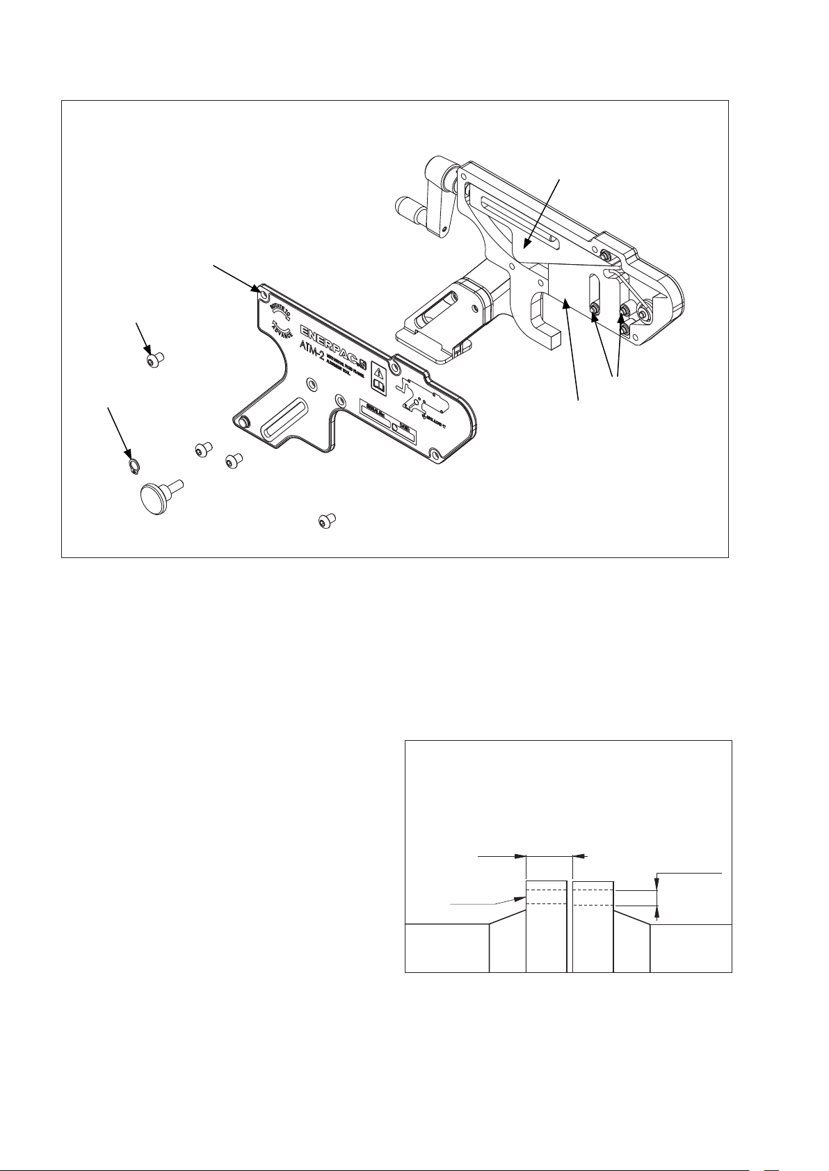
Figura 5. Ispezione e lubrificazione
COPERCHIO
VITE ESAGONALE
ANELLO ELASTICO
CUNEO GUIDA
CUNEO AZIONATO
CUSCINETTI
A SFERE
Nota: utilizzare il grasso Mobilgrease XHP ™ 222 o un
8.0 IMMAGAZZINAGGIO
grasso equivalente di ottima qualità per supporti usati con
carichi pesanti.
7.0 RISOLUZIONE DEI PROBLEMI
• L'attrezzo ATM-2 deve essere conservato in un luogo
• Le superfici lavorate devono essere unte con il grasso
PROBLEMA: L'ATTREZZO È COLLEGATO E SEMBRA
FUNZIONARE CORRETTAMENTE, MA IL
GIUNTO NON SI ALLINEA.
CAUSA: è presente un'ostruzione invisibile sul giunto
o sul tubo che lo circonda, oppure il carico
9.0 DIMENSIONI DELL'APPLICAZIONE
Figura 6. Dimensioni minime e massime della flangia
(immagine)
necessario per allineare il giunto è superiore
a quello dell'attrezzo ATM-2 (ovvero 1
tonnellata = 10 kN).
SOLUZIONE: a. Verificare che non siano presenti
ostruzioni nei pressi del giunto.
b. La pressione necessaria per allineare
il giunto potrebbe essere superiore
a quella di 1 tonnellata (10 kN)
offerta dall'attrezzo. In questo caso è
necessario adottare un altro metodo
per l'allineamento.
fresco e asciutto.
Mobilgrease XHP ™ 222 Special o un grasso equivalente
di ottima qualità per supporti usati con carichi pesanti.
Distanza minima 14 mm (0,55”)
Distanza massima 82 mm (3,23”)
Il gancio entra
in questo foro
del bullone
Dimensione minima
del foro del bullone
16 mm (0,63”)
2828
Page 29

ENERPAC
ADATTO ALL'USO CON L'ATTREZZO ATM-2 DI ENERPAC
NON ADATTO ALL'USO CON GLI ATTREZZI ATM DI
ADATTO ALL'USO CON L'ATTREZZO ATM-4 DI ENERPAC
ADATTO ALL'USO CON L'ATTREZZO ATM-9 DI ENERPAC
Nota: i modelli ATM-4 e ATM-9 sono illustrati a puro titolo
di riferimento.
ATM-4 ATM-4
ATM-2
Attrezzo ATM-2 ATM-4 ATM-9
connessione
3K
Classe
2 1-16" 2 9-16" 3 1-8" 4 1-16" 5 1-8" 7 1-16" 9" 11" 13 5-8" 16 3-4" 21 1-4"
Misura no-
minale tubo/
connessione
6K
1 13-16" 2 1-16" 2 9-16" 3 1-8" 4 1-16" 5 1-8" 7 1-16" 9" 11" 13 5-8" 16 3-4"
Attrezzo ATM-2 ATM-4 ATM-9
Classe
2 1-16" 2 9-16" 3 1-8" 4 1-16" 5 1-8" 7 1-16" 9" 11" 13 5-8" 16 3-4" 21 1-4"
Misura no-
minale tubo/
5" 6" 7" 8" 9" 10" 11" 12" 13" 14" 15" 16"
4
4"
3
4" 5" 6" 7" 8" 9" 10" 12" 13" 14" 15" 16" 17" 18" 19" 20"
4" 5" 6" 7" 8" 9" 10" 12" 13" 14" 15" 16" 17" 18" 19" 20" 21" 22" 23" 24" 27" 29" 30" 33" 35" 36" 39" 42" 45" 48"
3
3"
2
2"
4" 5" 6" 7" 8" 9" 10" 12" 13" 14" 15" 16" 17" 18" 19" 20" 21" 22" 23" 24" 29" 30" 33" 35" 36" 39" 42" 45" 48" 54" 60" 66" 72" 78" 84" 96" 108" 120"
1
1
4" 5" 6" 7" 8" 9" 10" 12" 13" 14" 15" 16" 17" 18" 19" 20" 21" 22" 23" 24" 26" 27" 29" 30" 33" 35" 36" 39" 42" 45" 48" 54" 60" 66" 72"
3
1/2"
1/2"
1/2"
1/2"
1/4"
4" 5" 6" 7" 8" 9" 10" 12" 13" 14" 15" 16" 17" 18" 19" 20" 21" 22" 23" 24" 27" 29" 30" 33" 35" 36" 39" 42" 45" 48"
3
3"
2
2"
1
1
1/2"
1/2"
1/2"
1/4"
4" 5" 6" 7" 8" 9" 10" 12" 13" 14" 15" 16" 17" 18" 19" 20" 21" 22" 23" 24"
3
1/2"
3
3"
2
1/2"
2
2"
1
1
1/2"
1/4"
1
1
4" 5" 6" 7" 8" 9" 10" 12" 13" 14" 15" 16" 17" 18" 19" 20" 21" 22" 23" 24"
3"
2"
1/2"
1/2"
1/2"
1/4"
3
3"
2
2"
1
1
1"
1/2"
1/2"
1/2"
1/4"
4" 5" 6" 7" 8" 9" 10" 12" 13" 14" 15" 16" 17" 18" 19" 20"
3
3"
2
2"
1
1
1"
1/2"
1/2"
1/2"
1/4"
3"
2
2"
1
1
1/2" 3/4" 1"
1/2"
1/2"
1/2"
1/2"
1/4"
5" 6" 7" 8" 9" 10" 11" 12" 13"
4
1/2"
4"
3
1/2"
3"
2
1/2"
2"
1
1/2"
1
1/4"
ATM-2 ATM-4 ATM-9
1/2" 3/4" 1"
1 13-16" 2 1-16" 2 9-16" 3 1-8" 4 1-16" 5 1-8" 7 1-16" 9" 11" 13 5-8" 16 3-4"
Attrezzo ATM-2 ATM-4 ATM-9
connessione
2K
Classe
2 1-16" 2 9-16" 3 1-8" 4 1-16" 5 1-8" 7 1-16" 9" 11" 13 5-8" 16 3-4" 21 1-4"
Misura no-
minale tubo/
1 13-16" 2 1-16" 2 9-16" 3 1-8" 4 1-16" 5 1-8" 7 1-16" 9" 11" 13 5-8" 16 3-4"
Misura no-
Area di applicazione della fl angia BS10
10.1
10.0 TABELLE SULL'AREA DI APPLICAZIONE
Attrezzo ATM-2 ATM-2
minale tubo/
connessione
Classe A
Misura no-
minale tubo/
connessione
Misura no-
Attrezzo ATM-2 ATM-4 ATM-9
minale tubo/
Classe D
Attrezzo ATM-2 ATM-4 ATM-9
connessione
Classe E
Misura no-
minale tubo/
connessione
Misura no-
Attrezzo ATM-2 ATM-4 ATM-9
Classe F
Attrezzo ATM-2 ATM-4
minale tubo/
connessione
Classe H
Misura no-
minale tubo/
connessione
Attrezzo ATM-2 ATM-4 ATM-9
Classe J
Misura no-
minale tubo/
connessione
29
29
Misura no-
Attrezzo ATM-2 ATM-4 ATM-9
minale tubo/
Classe K
Attrezzo ATM-2 ATM-4 ATM-9
connessione
Classe R
Misura no-
minale tubo/
connessione
Misura no-
Attrezzo ATM-2 ATM-4 ATM-9
Classe S
Attrezzo
minale tubo/
connessione
Classe T
Misura no-
Area di applicazione della fl angia da saldare di testa API6BX Area di applicazione della fl angia da saldare di testa API6B
10.2 10.3
Attrezzo ATM-2 ATM-4 ATM-9
minale tubo/
connessione
2K
Classe
Misura no-
Attrezzo ATM-2 ATM-4 ATM-9
minale tubo/
connessione
3K
Classe
Misura no-
minale tubo/
connessione
6K
Attrezzo ATM-4 ATM-9
Classe
Page 30

ADATTO ALL'USO CON L'ATTREZZO ATM-2 DI ENERPAC
ADATTO ALL'USO CON L'ATTREZZO ATM-4 DI ENERPAC
ADATTO ALL'USO CON L'ATTREZZO ATM-9 DI ENERPAC
NON ADATTO ALL'USO CON GLI ATTREZZI ATM DI ENERPAC
Nota: i modelli ATM-2 e ATM-4 sono illustrati a puro titolo
di riferimento.
22" 26" 28" 30" 32" 34" 36" 38" 40" 42" 44" 46" 48"
Misura no-
minale tubo/
Area di applicazione della fl angia ASME B16.47
4" 5" 6" 8" 10" 12" 14" 16" 18" 20" 24"
3
3"
2
2"
1
1
3/4" 1"
Attrezzo ATM-4 ATM-9
connessione
150
Classe
1/2"
1/2"
1/2"
1/4"
22" 26" 28" 30" 32" 34" 36" 38" 40" 42" 44" 46" 48"
Misura no-
minale tubo/
connessione
4" 5" 6" 8" 10" 12" 14" 16" 18" 20" 24"
3
1/2"
3"
2
1/2"
2"
1
1/2"
1
1/4"
3/4" 1"
Attrezzo ATM-4 ATM-9
300
Classe
22" 26" 28" 30" 32" 34" 36" 38" 40" 42" 44" 46" 48"
Misura no-
minale tubo/
connessione
4" 5" 6" 8" 10" 12" 14" 16" 18" 20" 24"
3
1/2"
3"
2
1/2"
2"
1
1/2"
1
1/4"
3/4" 1"
Attrezzo ATM-4 ATM-9
400
Classe
22" 26" 28" 30" 32" 34" 36" 38" 40" 42" 44" 46" 48"
Misura no-
minale tubo/
connessione
4" 5" 6" 8" 10" 12" 14" 16" 18" 20" 24"
3
1/2"
3"
2
1/2"
2"
1
1/2"
1
1/4"
3/4" 1"
Attrezzo ATM-4 ATM-9
600
Classe
22" 26" 28" 30" 32" 34" 36" 38" 40" 42" 44" 46" 48"
Misura no-
minale tubo/
connessione
3" 4" 5" 6" 8" 10" 12" 14" 16" 18" 20" 24"
2
1/2"
2"
1
1/2"
1
1/4"
1/2" 3/4" 1"
Attrezzo ATM-9
900
Classe
9
ATM-
1/2"
1/2"
3" 4" 5" 6" 7" 8" 10" 12" 14" 16" 18" 20" 24" 28" 32" 36" 40"
2
1/2"
2"
1
1/2"
1
1/4"
3" 4" 5" 6" 7" 8" 10" 12" 14" 16" 18" 20"
2
1/2"
3" 4" 5" 6" 7" 8" 10" 12" 14" 16"
2
2"
1
1/2"
1/2"
3" 4" 5" 6" 7" 8" 10" 12" 14"
2
2"
1
2"
1
1/2" 3/4" 1"
1/2"
3/4" 1"
1/2" 3/4" 1"
3" 4" 5" 6" 8" 10" 12" 14" 16" 18" 20" 24"
2
2"
1
1
1/2"
1/2"
1/4"
3" 4" 5" 6" 8" 10" 12" 14" 16" 18" 20" 24"
2
1/2"
2"
1
1/2"
1
1/4"
3" 4" 5" 6" 7" 8" 10" 12" 14" 16" 18" 20" 24" 28" 32" 36" 40" 48" 56 72" 80"
2
2"
1/2" 3/4" 1"
1/2" 3/4" 1"
1
1/2"
1/2"
3" 4" 5" 6" 7" 8" 10" 12"
2
1/2"
2"
1
1/2"
3/8" 1/2" 3/4" 1"
Misura no-
Area di applicazione della fl angia ASME B16.5
10.4 10.6
10.0 TABELLE SULL'AREA DI APPLICAZIONE (continua)
Attrezzo ATM-2 ATM-4
minale tubo/
connessione
150
Classe
Misura no-
minale tubo/
connessione
Attrezzo ATM-2 ATM-4 ATM-9
300
Classe
Misura no-
minale tubo/
connessione
Attrezzo ATM-2 ATM-4 ATM-9
400
Classe
Misura no-
minale tubo/
connessione
Attrezzo ATM-2 ATM-4 ATM-9
600
Classe
Misura no-
minale tubo/
connessione
Attrezzo ATM-2 ATM-4 ATM-9
900
Classe
Misura no-
minale tubo/
connessione
Attrezzo ATM-2 ATM-4 ATM-9
1500
Classe
Misura no-
minale tubo/
connessione
30
30
Attrezzo ATM-2 ATM-4 ATM-9
2500
Classe
Misura no-
Attrezzo ATM-2 ATM-4 ATM-9
minale tubo/
connessione
PN16
Classe
Area di applicazione della fl angia da saldare di testa DIN
10.5
Misura no-
minale tubo/
connessione
Attrezzo ATM-2 ATM-4
PN25
Classe
Misura no-
minale tubo/
connessione
Attrezzo ATM-2 ATM-4
PN40
Classe
Misura no-
minale tubo/
connessione
Attrezzo ATM-2 ATM-4
PN54
Classe
Misura no-
minale tubo/
connessione
Misura no-
Attrezzo ATM-2 ATM-4 ATM-9
PN100
Classe
Attrezzo ATM-2 ATM-4 ATM-9
minale tubo/
connessione
PN160
Classe
Page 31

ADATTO ALL'USO CON L'ATTREZZO ATM-2 DI ENERPAC
ADATTO ALL'USO CON L'ATTREZZO ATM-4 DI ENERPAC
ADATTO ALL'USO CON L'ATTREZZO ATM-9 DI ENERPAC
NON ADATTO ALL'USO CON GLI ATTREZZI ATM DI ENERPAC
Nota: i modelli ATM-2 e ATM-4 sono illustrati a puro titolo
di riferimento.
4" 5" 6" 8" 10" 12" 14" 16" 18" 20" 22" 24" 26" 28" 30" 32" 34" 36" 38" 40" 42" 44" 46" 48"
3
3"
2
Misura
nominale tubo/
10.7
Area di applicazione della fl angia SPO
1/2"
1/2"
Attrezzo ATM-2 ATM-4
connessione
150
Classe
4" 5" 6" 8" 10" 12" 14" 16" 18" 20" 22" 24" 26" 28" 30" 32" 34" 36" 38" 40" 42" 44" 46" 48"
3
1/2"
3"
2
1/2"
Misura
Attrezzo ATM-2 ATM-4 ATM-9
connessione
nominale tubo/
300
Classe
4" 5" 6" 8" 10" 12" 14" 16" 18" 20" 22" 24" 26" 28" 30" 32" 34" 36" 38" 40" 42" 44" 46" 48"
3
1/2"
3"
2
1/2"
Misura
Attrezzo ATM-4 ATM-9
connessione
nominale tubo/
600
Classe
4" 5" 6" 8" 10" 12" 14" 16" 18" 20" 22" 24" 26" 28" 30" 32" 34" 36" 38" 40" 42" 44" 46" 48"
3
1/2"
3"
2
1/2"
Misura
connessione
nominale tubo/
900
Classe
Attrezzo ATM-4 ATM-9
3
2
Misura
4" 5" 6" 8" 10" 12" 14" 16" 18" 20" 22" 24" 26" 28" 30" 32" 34" 36" 38" 40" 42" 44" 46" 48"
1/2"
3"
1/2"
Attrezzo ATM-4 ATM-9
connessione
nominale tubo/
1500
Classe
4" 5" 6" 8" 10" 12" 14" 16" 18" 20" 22" 24"
3
1/2"
3"
2
1/2"
Misura
connessione
nominale tubo/
2500
10.0 TABELLE SULL'AREA DI APPLICAZIONE (continua)
31
31
Attrezzo ATM-4 ATM-9
Classe
4" 5" 6" 8" 10" 12" 14" 16" 18" 20" 22" 24"
3
1/2"
3"
2
1/2"
Misura
connessione
nominale tubo/
5000
Attrezzo ATM-4 ATM-9
Classe
4" 5" 6" 8" 10" 12" 14" 16" 18" 20" 22" 24"
3
1/2"
3"
2
1/2"
Misura
Attrezzo ATM-4 ATM-9
connessione
nominale tubo/
7500
Classe
4" 5" 6" 8" 10" 12" 14" 16" 18" 20" 22" 24"
3
1/2"
3"
2
1/2"
Misura
Attrezzo ATM-4 ATM-9
connessione
nominale tubo/
10000
Classe
4" 5" 6" 8" 10" 12" 14" 16" 18" 20" 22" 24"
3
1/2"
3"
2
1/2"
Misura
Attrezzo ATM-4 ATM-9
connessione
nominale tubo/
15000
Classe
Page 32

11.0 PESO E DIMENSIONI
PESO
Nota: i pesi indicati sono approssimativi.
Attrezzo, cricchetto e cinghia ................................................... 2,0 kg [4,4 lb]
Scatola, confezione e manuale di istruzioni ........................................0,4 kg [0,9 lb]
DIMENSIONI
Estensione minima
151 mm
[5.94"]
37 mm
[1.46"]
38 mm
[1.50"]
37 mm
[1.46"]
50 mm
[1.99"]
54 mm
[2.13"]
Estensione massima
11 mm
[0.43"]
82 mm
[3.23"]
35 mm
[1.38"]
50 mm
[1.99"]
91 mm
[3.58"]
32
32
21 mm
[0.83"]
72 mm
[2.83"]
Page 33

L4060 Rev. B 02/14
Hoja de Instrucciones
Herramienta de
alineación de bridas
Modelo ATM-2
Párrafo página
1.0 Instrucciones de recepción .......................................................34
2.0 Aspectos de seguridad ..........................................................34
3.0 Descripción del producto ........................................................34
4.0 Instrucciones de funcionamiento ...................................................35
5.0 Revisión - mantenimiento ........................................................35
6.0 Inspección y lubricación .........................................................35
7.0 Solución de problemas ..........................................................36
8.0 Almacenamiento ...............................................................36
9.0 Dimensiones de aplicación .......................................................36
10.0 Tablas de aplicación ...........................................................37-39
11.0 Pesos y dimensiones ............................................................40
3333
Page 34

1.0 INSTRUCCIONES DE RECEPCIÓN
Inspeccione visualmente todos los componentes en busca
de posibles daños ocasionados durante el transporte. La
garantía no cubre los daños sufridos durante el transporte.
herramienta o de la pieza.
Si se encuentran daños producidos durante el transporte,
informe de inmediato al transportista. El transportista es
responsable de todos los gastos de reparación y sustitución
ocasionados por daños producidos durante el transporte.
disponen de cabezales cuadrados y hexagonales para
seGuridad ante todo
aflojar o apretar pernos y tuercas. Utilice cortatuercas de
Enerpac en caso de que no se pueda sacar una tuerca.
Lea todas las instrucciones, advertencias y precauciones
atentamente. Siga todas las precauciones de seguridad
para evitar daños personales o materiales durante el
funcionamiento del sistema. Enerpac no asume ninguna
responsabilidad de daños o lesiones producidos por un
uso inadecuado del producto, falta de mantenimiento
o incorrecto funcionamiento del producto y/o sistema.
producir una sobrecarga si se quitan los pernos durante la
instalación de la herramienta y la fuerza resultante es
mayor que la carga de trabajo segura de la herramienta.
Póngase en contacto con Enerpac en caso de duda
acerca de las precauciones de seguridad y aplicaciones.
3.0 DESCRIPCIÓN DEL PRODUCTO
ADVERTENCIA: Utilice siempre gafas de
seguridad. El operario debe tomar las
precauciones necesarias contra lesiones que
podrían producirse debido a fallos de la
Recomendamos el uso de líquidos o líquidos
en spray especiales para aflojar tuercas. Las
llaves dinamométricas hidráulicas Enerpac
ADVERTENCIA: No ajuste nunca la ATM-2 a
una junta hasta que no se hayan aflojado y
quitado los pernos de la brida. Se puede
Una PRECAUCIÓN se utiliza para indicar los procedimientos
correctos de funcionamiento y mantenimiento y las
prácticas para evitar daños en, o la destrucción del equipo
La herramienta de alineación ATM-2 ha sido desarrollada
como la solución sencilla para una pequeña desalineación
de bridas a baja presión.
y otra propiedad.
Las juntas de brida pueden quedar desalineadas cuando
Una ADVERTENCIA indica un posible peligro que requiere
procedimientos o prácticas correctas para evitar daños
personales.
se separan para realizar ensayos, mantenimiento
rutinario o durante paradas programadas. Una alineación
final también puede ser necesaria durante la fase de
construcción, cuando se instala un nuevo tubo. Los
2.0 ASPECTOS DE SEGURIDAD
métodos actuales de manipulación de bridas suelen ser
peligrosos porque requieren mucha fuerza de elevación
Omisión de cumplir con los
manual y pueden dañar los orificios para los pernos.
siguientes avisos y advertencias
puede dañar el equipo y conducir a
Fig. 1 Una junta de brida desalineada
lesiones personales.
IMPORTANTE: La edad mínima del operario
es de 18 años. El operario debe haber leído y
entendido todas las instrucciones, los
aspectos de seguridad, precauciones y advertencias
antes de empezar a operar el equipo de Enerpac. El
operario es responsable de estas actividades ante otras
personas.
PRECAUCIÓN: Asegúrese de que todos los
PUNTO DE MÁX.
DESALINEACIÓN
componentes del sistema están protegidos
contra factores externos de daños tales como
calor excesivo, llamas, partes móviles de máquinas,
bordes afilados y sustancias químicas corrosivas.
La herramienta de alineación ATM-2 ha sido desarrollada
como la solución sencilla. Es:
PUNTO DE MÁX.
DESALINEACIÓN
ADVERTENCIA: Sustituya inmediatamente
las piezas desgastadas o dañadas por piezas
originales de Enerpac. Las piezas de Enerpac
están diseñadas para ajustar adecuadamente
y resisten las cargas nominales.
• Segura
• Fácil de usar
• No daña otros componentes
• Capaz de generar 1 tonelada [10 kN] de carga
• Puede utilizarse en muchos tamaños populares de bridas
3434
Page 35

4.0 INSTRUCCIONES DE FUNCIONAMIENTO
Fig. 4 Alineamiento
1. Determine el punto de máxima desalineación.
MANIVELA
2. Conduzca el gancho de elevación de la herramienta en el
orificio del perno en el punto de máxima desalineación.
La pata extensible debe soltarse y bajarse en el tubo,
manteniendo al mismo tiempo el gancho nivelado en
el orificio del perno. En esta posición debe asegurarse
apretando el tornillo moleteado. Véase fig. 2.
Fig. 2 Montaje de la herramienta en la brida
Fuerza máxima de manivela recomendada = 200 N [45 lbf].
ACCIONE LA MANIVELA SOLO A MANO - ¡NO UTILICE
HERRAMIENTAS!
6. Después de retirar la herramienta de la brida, coloque
PARALELO
GANCHO DE
ELEVACIÓN
TORNILLO
MOLETEADO
PATA
EXTENSIBLE
5.0 REVISIÓN - MANTENIMIENTO
• Después de acabar el trabajo y antes de volver a utilizar la
3. Gire la manivela en el sentido de las agujas del reloj
hasta que la cuña haga contacto con la brida opuesta.
Pase la correa por la ranura en la base de la pata
• Sustituya todos las piezas que falten o estén dañadas lo
extensible, conduzca el extremo de la correa por la
hebilla y cierre el broche. Véase fig. 3.
Fig. 3 Montaje de la correa
• Engrase regularmente todas las piezas móviles con
• Guarde todas las piezas que no utilice en la caja de
el último perno en el orificio vacío que queda.
herramienta, debe comprobarse si la herramienta ATM-2
está completa y deben revisarse los componentes para
asegurar de que están en buen estado.
más pronto posible y antes de que vuelvan a utilizarse.
la grasa especial Mobilgrease XHP ™ 222 Special.
Consulte el párrafo 6.0.
transporte.
ABERTURA
CORREA
6.0 INSPECCIÓN Y LUBRICACIÓN
(Véase fig. 5 en la siguiente página)
PASO 1. Coloque la herramienta plana sobre el banco
CORREA
PASO 2. Con un destornillador pequeño y plano, retire la
4. Gire la manivela hasta que se haya logrado la alineación.
Véase fig. 4.
PASO 3. Retire la cubierta y limpie toda la suciedad o
ADVERTENCIA: No exceda las 200 N [45 lbf]
de presión manual en la manivela. Si se
ejerce más fuerza puede romperse la
PASO 4. Compruebe si los componentes están
manivela. No utilice nunca herramientas para girar la
manivela.
5. Cuando se haya finalizado el alineamiento, pueden
insertarse y apretarse los pernos de la brida. Después
de volver a colocar todos los pernos en todos los
orificios vacíos (excepto el orificio en el que se ha
insertado el gancho de elevación), puede retirar la
herramienta en orden inverso a los pasos 1 a 4.
Nota: Utilice la grasa Mobilgrease XHP ™ 222 Special
o una grasa para rodamientos equivalente de alto
rendimiento y buena calidad.
3535
de trabajo.
arandela de retención. A continuación, saque
los cinco tornillos Allen de 4mm.
corrosión de la piezas móviles.
desgastados o dañados. Cámbielos si es
necesario. Si no están dañados, engrase las
piezas y vuélvalas a montar en orden inverso a
los pasos 1 a 4.
Page 36

Fig. 5 Inspección y lubricación
CUBIERTA
TORNILLO ALLEN
ARANDELA DE RETENCIÓN
CUÑA
CUÑA
RODAMIENTO
DE AGUJAS
7.0 SOLUCIÓN DE PROBLEMAS
PROBLEMA: LA HERRAMIENTA ESTÁ
CONECTADA Y PARECE FUNCIONAR
8.0 ALMACENAMIENTO
• La ATM-2 debe guardarse en un lugar fresco y seco.
• En las superficies mecanizadas ha de aplicarse grasa
CORRECTAMENTE, PERO LA JUNTA NO
SE ALINEA.
CAUSA: Una obstrucción oculta en la junta o
alrededor del tubo, o la carga necesaria
9.0 DIMENSIONES DE APLICACIÓN
para alinear la junta es mayor que la de
ATM-2 (a saber 1 tonelada [10 kN] ).
Fig 6 Tamaños mín. y máx. de brida (visual)
SOLUCIÓN: a. Compruebe si en la proximidad de la
junta hay obstrucciones.
b. Puede que la presión necesaria para
alinear la junta sea mayor que la 1
tonelada [10 kN] de carga límite de
la herramienta. En este caso debe
aplicarse otro método para alinear la
junta.
Mobilgrease XHP ™ 222 Special o una grasa para
rodamientos equivalente de alto rendimiento y buena
calidad.
Distancia mín. 14 mm [0,55 pulg.]
Distancia máx. 82 mm [3,23 pulg.]
Gancho en este
orificio de perno
Tamaño mín. orificio
de perno
16 mm [0,63 pulg.]
3636
Page 37

ATM DE ENERPAC
APROPIADO PARA HERRAMIENTA DE ENERPAC ATM-4
ATM-2 ATM-4 ATM-9
APROPIADO PARA HERRAMIENTA DE ENERPAC ATM-9
5" 6" 7" 8" 9" 10" 11" 12" 13" 14" 15" 16"
4
4"
3
3"
2
2"
1
1
1/2"
1/2"
1/2"
1/2"
1/4"
NO APROPIADO PARA CUALQUIER HERRAMIENTA
Nota: Los modelos ATM-4 y ATM-9 se muestran solamente para
propósitos de referencia.
ATM-2 ATM-4 ATM-9
mienta
NPS 2 1-16" 2 9-16" 3 1-8" 4 1-16" 5 1-8" 7 1-16" 9" 11" 13 5-8" 16 3-4" 21 1-4"
Herra-
6K
ATM-2 ATM-4 ATM-9
mienta
Clase
ATM-4 ATM-9
ATM-2 ATM-4 ATM-9
ATM-2 ATM-4 ATM-9
NPS 2 1-16" 2 9-16" 3 1-8" 4 1-16" 5 1-8" 7 1-16" 9" 11" 13 5-8" 16 3-4" 21 1-4"
5" 6" 7" 8" 9" 10" 11" 12" 13"
4
1/2"
4"
3
1/2"
3"
2
1/2"
2"
1
1/2"
1
1/4"
ATM-2 ATM-4 ATM-9
Herra-
2K
mienta
Clase
ATM-2 ATM-4 ATM-9
NPS 2 1-16" 2 9-16" 3 1-8" 4 1-16" 5 1-8" 7 1-16" 9" 11" 13 5-8" 16 3-4" 21 1-4"
Herra-
3K
Clase
ATM-2 ATM-4 ATM-9
APROPIADO PARA HERRAMIENTA DE ENERPAC ATM-2
ATM-4 ATM-4
ATM-2
ATM-2 ATM-4 ATM-9
ATM-2 ATM-4 ATM-9
1/2"
1/2"
1/2"
1/4"
ATM-2 ATM-4 ATM-9
4" 5" 6" 7" 8" 9" 10" 12" 13" 14" 15" 16" 17" 18" 19" 20"
3
3"
2
2"
1
1
ATM-2 ATM-4 ATM-9
ATM-2 ATM-2
4" 5" 6" 7" 8" 9" 10" 12" 13" 14" 15" 16" 17" 18" 19" 20" 21" 22" 23" 24" 26" 27" 29" 30" 33" 35" 36" 39" 42" 45" 48" 54" 60" 66" 72"
3
1/2"
4" 5" 6" 7" 8" 9" 10" 12" 13" 14" 15" 16" 17" 18" 19" 20" 21" 22" 23" 24" 27" 29" 30" 33" 35" 36" 39" 42" 45" 48"
3
3"
2
2"
1
1
1/2"
1/2"
1/2"
1/4"
4" 5" 6" 7" 8" 9" 10" 12" 13" 14" 15" 16" 17" 18" 19" 20" 21" 22" 23" 24" 27" 29" 30" 33" 35" 36" 39" 42" 45" 48"
3
3"
2
2"
1
1
1/2"
1/2"
1/2"
1/4"
4" 5" 6" 7" 8" 9" 10" 12" 13" 14" 15" 16" 17" 18" 19" 20" 21" 22" 23" 24"
3
3"
2
2"
1
1
1/2"
1/2"
1/2"
1/4"
ATM-2 ATM-4
4" 5" 6" 7" 8" 9" 10" 12" 13" 14" 15" 16" 17" 18" 19" 20" 21" 22" 23" 24"
3
3"
2
2"
1
1
1/2"
1/2"
1/2"
1/4"
ATM-2 ATM-4 ATM-9
4" 5" 6" 7" 8" 9" 10" 12" 13" 14" 15" 16" 17" 18" 19" 20"
3
1/2"
3"
2
1/2"
2"
1
1/2"
1
1/4"
NPS
Gama de aplicaciones de bridas BS10
10.1
10.0 TABLAS DE APLICACIÓN
Herra-
mienta
Clase A
NPS 4" 5" 6" 7" 8" 9" 10" 12" 13" 14" 15" 16" 17" 18" 19" 20" 21" 22" 23" 24" 29" 30" 33" 35" 36" 39" 42" 45" 48" 54" 60" 66" 72" 78" 84" 96" 108" 120"
Herra-
mienta
Clase D
NPS
Herra-
mienta
Clase E
NPS
Herra-
mienta
Clase F
NPS
Herra-
mienta
Clase H
NPS
Herra-
mienta
Clase J
NPS 1"
37
37
Herra-
mienta
Clase K
NPS 1"
Herra-
mienta
Clase R
NPS 1/2" 3/4" 1"
Herra-
mienta
Clase S
NPS 1/2" 3/4" 1"
Herra-
mienta
Clase T
NPS 1 13-16" 2 1-16" 2 9-16" 3 1-8" 4 1-16" 5 1-8" 7 1-16" 9" 11" 13 5-8" 16 3-4"
Gama de aplicaciones de bridas de cuello soldable API6BX Gama de aplicaciones de bridas de cuello soldable API6B
10.2 10.3
Herra-
2K
mienta
Clase
NPS 1 13-16" 2 1-16" 2 9-16" 3 1-8" 4 1-16" 5 1-8" 7 1-16" 9" 11" 13 5-8" 16 3-4"
Herra-
3K
mienta
Clase
NPS 1 13-16" 2 1-16" 2 9-16" 3 1-8" 4 1-16" 5 1-8" 7 1-16" 9" 11" 13 5-8" 16 3-4"
Herra-
6K
mienta
Clase
Page 38

ATM DE ENERPAC
ATM-4 ATM-9
mienta
NPS 22" 26" 28" 30" 32" 34" 36" 38" 40" 42" 44" 46" 48"
Herra-
400
Clase
ATM-4 ATM-9
ATM-4 ATM-9
NPS 22" 26" 28" 30" 32" 34" 36" 38" 40" 42" 44" 46" 48"
Gama de aplicaciones de bridas ASME B16.47
Herra-
150
Clase
mienta
NPS 22" 26" 28" 30" 32" 34" 36" 38" 40" 42" 44" 46" 48"
Herra-
300
Clase
mienta
NPS 22" 26" 28" 30" 32" 34" 36" 38" 40" 42" 44" 46" 48"
Herra-
600
Clase
ATM-4 ATM-9
mienta
NPS 22" 26" 28" 30" 32" 34" 36" 38" 40" 42" 44" 46" 48"
Herra-
900
Clase
ATM-9
mienta
ATM-
APROPIADO PARA HERRAMIENTA DE ENERPAC ATM-2
9
APROPIADO PARA HERRAMIENTA DE ENERPAC ATM-4
APROPIADO PARA HERRAMIENTA DE ENERPAC ATM-9
NO APROPIADO PARA CUALQUIER HERRAMIENTA
Nota: Los modelos ATM-4 y ATM-9 se muestran solamente para
propósitos de referencia.
4" 5" 6" 8" 10" 12" 14" 16" 18" 20" 24"
3
3"
2
2"
1
1
NPS 3/4" 1"
Gama de aplicaciones de bridas ASME B16.5
10.4 10.6
10.0 TABLAS DE APLICACIÓN (continuación)
1/2"
1/2"
1/2"
1/4"
ATM-2 ATM-4
Herra-
150
Clase
3
2
1
1
mienta
4" 5" 6" 8" 10" 12" 14" 16" 18" 20" 24"
3"
2"
NPS 3/4" 1"
1/2"
1/2"
1/2"
1/4"
Herra-
300
Clase
ATM-2 ATM-4 ATM-9
mienta
4" 5" 6" 8" 10" 12" 14" 16" 18" 20" 24"
3
3"
2
2"
1
1
NPS 3/4" 1"
1/2"
1/2"
1/2"
1/4"
Herra-
400
Clase
ATM-2 ATM-4 ATM-9
mienta
4" 5" 6" 8" 10" 12" 14" 16" 18" 20" 24"
3
3"
2
2"
1
1
NPS 3/4" 1"
1/2"
1/2"
1/2"
1/4"
Herra-
600
Clase
ATM-2 ATM-4 ATM-9
mienta
3" 4" 5" 6" 8" 10" 12" 14" 16" 18" 20" 24"
2
2"
1
1
NPS 1/2" 3/4" 1"
1/2"
1/2"
1/4"
Herra-
900
Clase
ATM-2 ATM-4 ATM-9
mienta
3" 4" 5" 6" 8" 10" 12" 14" 16" 18" 20" 24"
2
1/2"
2"
1
1/2"
1
1/4"
ATM-2 ATM-4 ATM-9
NPS 1/2" 3/4" 1"
Herra1500
Clase
2
1
1
mienta
3" 4" 5" 6" 8" 10" 12" 14" 16" 18" 20" 24"
2"
NPS 1/2" 3/4" 1"
1/2"
1/2"
1/4"
38
38
ATM-2 ATM-4 ATM-9
Herra2500
Clase
mienta
ATM-2 ATM-4
3" 4" 5" 6" 7" 8" 10" 12" 14" 16" 18" 20" 24" 28" 32" 36" 40"
ATM-2 ATM-4 ATM-9
2
1/2"
2"
1
1/2"
1
3" 4" 5" 6" 7" 8" 10" 12" 14" 16" 18" 20" 24" 28" 32" 36" 40" 48" 56 72" 80"
2
1/2"
2"
1
1/2"
NPS
Gama de aplicaciones de bridas de cuello soldable DIN
10.5
Herra-
PN16
Clase
mienta
NPS 1/2" 3/4" 1"
1/4"
Herra-
PN25
Clase
2
1
mienta
3" 4" 5" 6" 7" 8" 10" 12" 14" 16" 18" 20"
2"
NPS
1/2"
1/2"
ATM-2 ATM-4
Herra-
mienta
PN40
Clase
3" 4" 5" 6" 7" 8" 10" 12" 14" 16"
2
2"
1
NPS 3/4" 1"
1/2"
1/2"
ATM-2 ATM-4
Herra-
PN54
Clase
2
1
mienta
3" 4" 5" 6" 7" 8" 10" 12" 14"
2"
NPS 1/2" 3/4" 1"
1/2"
1/2"
ATM-2 ATM-4 ATM-9
Herra-
mienta
PN100
Clase
3" 4" 5" 6" 7" 8" 10" 12"
2
1/2"
2"
ATM-2 ATM-4 ATM-9
1
1/2"
NPS 3/8" 1/2" 3/4" 1"
Herra-
mienta
PN160
Clase
Page 39

ATM DE ENERPAC
APROPIADO PARA HERRAMIENTA DE ENERPAC ATM-4
4" 5" 6" 8" 10" 12" 14" 16" 18" 20" 22" 24"
3
3"
2
1/2"
1/2"
APROPIADO PARA HERRAMIENTA DE ENERPAC ATM-9
ATM-4 ATM-9
NO APROPIADO PARA CUALQUIER HERRAMIENTA
Nota: Los modelos ATM-4 y ATM-9 se muestran solamente para
propósitos de referencia.
4" 5" 6" 8" 10" 12" 14" 16" 18" 20" 22" 24"
3
1/2"
ATM-4 ATM-9
3"
2
1/2"
APROPIADO PARA HERRAMIENTA DE ENERPAC ATM-2
ATM-4 ATM-9
ATM-2 ATM-4 ATM-9
4" 5" 6" 8" 10" 12" 14" 16" 18" 20" 22" 24" 26" 28" 30" 32" 34" 36" 38" 40" 42" 44" 46" 48"
3
3"
2
1/2"
1/2"
ATM-2 ATM-4
4" 5" 6" 8" 10" 12" 14" 16" 18" 20" 22" 24" 26" 28" 30" 32" 34" 36" 38" 40" 42" 44" 46" 48"
3
3"
2
1/2"
1/2"
4" 5" 6" 8" 10" 12" 14" 16" 18" 20" 22" 24" 26" 28" 30" 32" 34" 36" 38" 40" 42" 44" 46" 48"
3
1/2"
3"
2
1/2"
ATM-4 ATM-9
ATM-4 ATM-9
4" 5" 6" 8" 10" 12" 14" 16" 18" 20" 22" 24" 26" 28" 30" 32" 34" 36" 38" 40" 42" 44" 46" 48"
4" 5" 6" 8" 10" 12" 14" 16" 18" 20" 22" 24" 26" 28" 30" 32" 34" 36" 38" 40" 42" 44" 46" 48"
3
2
3
1/2"
3"
3"
2
1/2"
1/2"
1/2"
4" 5" 6" 8" 10" 12" 14" 16" 18" 20" 22" 24"
ATM-4 ATM-9
3
1/2"
3"
2
1/2"
ATM-4 ATM-9
4" 5" 6" 8" 10" 12" 14" 16" 18" 20" 22" 24"
3
3"
2
1/2"
1/2"
4" 5" 6" 8" 10" 12" 14" 16" 18" 20" 22" 24"
ATM-4 ATM-9
3
1/2"
3"
2
1/2"
NPS
10.7
Gama de aplicaciones de bridas SPO
Herramienta
150
Clase
NPS
Herramienta
300
Clase
NPS
Herramienta
600
Clase
NPS
Herramienta
900
Clase
10.0 TABLAS DE APLICACIÓN (continuación)
NPS
Herramienta
1500
Clase
39
39
NPS
Herramienta
2500
Clase
NPS
Herramienta
5000
Clase
NPS
Herramienta
7500
Clase
NPS
Herramienta
10000
Clase
NPS
Herramienta
15000
Clase
Page 40

11.0 PESOS Y DIMENSIONES
PESOS
Nota: Los pesos indicados son aproximados.
Herramienta, carraca y correa .................................................2,0 kg [4,4 lbs.]
Caja, envase y manual de instrucciones .........................................0,4 kg [0,9 lbs.]
DIMENSIONES
Extensión mínima
151 mm
[5.94"]
37 mm
[1.46"]
38 mm
[1.50"]
37 mm
[1.46"]
50 mm
[1.99"]
54 mm
[2.13"]
Extensión máxima
11 mm
[0.43"]
82 mm
[3.23"]
35 mm
[1.38"]
50 mm
[1.99"]
91 mm
[3.58"]
40
40
21 mm
[0.83"]
72 mm
[2.83"]
Page 41

L4060 Rev. B 02/14
Handleiding
Flensuitlijngereedschap
Model ATM-2
Paragraaf pagina
1.0 Instructies ontvangen ............................................................42
2.0 Veiligheid .....................................................................42
3.0 Productbeschrijving .............................................................42
4.0 Bedieningsinstructies ............................................................43
5.0 Controle - Onderhoud ...........................................................43
6.0 Inspectie en smering ............................................................43
7.0 Foutopsporing .................................................................44
8.0 Opslag .......................................................................44
9.0 Toepassingsafmetingen ..........................................................44
10.0 Toepassingstabellen ...........................................................45-47
11.0 Gewicht en afmetingen ..........................................................48
4141
Page 42

1.0 INSTRUCTIES BIJ ONTVANGST
Controleer alle onderdelen op transportschade.
Transportschade wordt niet gedekt door de garantie.
Breng de vervoerder direct op de hoogte als u
transportschade ontdekt. De vervoerder is aansprakelijk
voor alle kosten die voortvloeien uit reparaties of
vervanging als gevolg van transportschade.
veiLiGheid voorop
Lees alles instructies en waarschuwingen goed door.
Volg alle veiligheidsinstructies goed op om persoonlijk
letsel en beschadigingen aan eigendommen
tijdens het gebruik van het systeem te voorkomen.
Enerpac is niet aansprakelijk voor beschadiging of
letsel als gevolg van onveilig of onjuist gebruik of
achterstallig onderhoud van het product of systeem.
Neem bij twijfel over veiligheidsmaatregelen en
toepassingsgebieden contact op met Enerpac.
LET OP geeft de juiste gebruiks- of onderhoudsprocedure aan en de werkwijze om schade aan of
vernietiging van de apparatuur of andere apparaten
te voorkomen.
Een WAARSCHUWING geeft een potentieel gevaar
aan dat vraagt om een correcte procedure of juist
gebruik om persoonlijk letsel te voorkomen.
2.0 VEILIGHEID
Als u zich niet aan de waarschuwingen houdt die hieronder
vermeld worden, kan dit
beschadiging van de apparatuur en persoonlijk letsel
tot gevolg hebben.
BELANGRIJK: De operator moet minimaal
18 jaar oud zijn. De operator moet alle
instructies, veiligheids voor schriften en
waarschuwingen zorgvuldig doorgelezen en begrepen
hebben voordat hij of zij de Enerpac-apparatuur gaat
gebruiken. De operator is tijdens het gebruik van de
apparatuur ook verantwoordelijk voor derden.
WAARSCHUWING: Draag altijd een
veiligheidsbril. De operator moet ook
maatregelen nemen om letsel als gevolg
van storing van de apparatuur of het
werkstuk te voorkomen.
Gebruik speciale vloeistof of spray om
vastzittende delen los te maken. De
hydraulische momentsleutels van Enerpac
hebben vierkante en zeshoekige aandrijfeenheden
om moeren en schroeven los of vast te draaien. Bij
Enerpac is tevens een moersplitter verkrijgbaar als
een moer niet kan worden verwijderd.
WAARSCHUWING: Plaats de ATM-2
altijd pas op een verbinding nadat de
bouten van de flens zijn losgedraaid en
verwijderd. Als de bouten worden verwijderd wanneer
het gereedschap is geïnstalleerd en de resulterende
kracht groter is dan de veilige werkbelasting van het
gereedschap, kan overbelasting ontstaan.
3.0 PRODUCTBESCHRIJVING
Het uitlijngereedschap ATM-2 is een eenvoudige
oplossing voor kleine uitlijningsfouten van flenzen
die onder lage druk staan.
Uitlijningsfouten van flensverbindingen komen
vaak voor als deze zijn losgemaakt voor tests,
routineonderhoud of tijdens shutdowns. Ook als een
nieuwe pijpleiding wordt geplaatst, kan een nieuwe
uitlijning nodig zijn. Bestaande methoden voor
flensuitlijning zijn door veel handmatig heffen vaak
gevaarlijk en kunnen de boutgaten beschadigen.
Fig. 1 Een foutief uitgelijnde verbinding
PUNT VAN
MAX. FOUTIEVE
UITLIJNING
LET OP: Zorg ervoor dat alle systeemonderdelen worden beschermd tegen
beschadiging veroorzaakt door externe
factoren zoals extreme hitte, vlammen, bewegende
machineonderdelen, scherpe randen en corroderende
chemicaliën.
WAARSCHUWING: Vervang versleten of
beschadigde onderdelen direct door de
juiste Enerpac-onderdelen. Enerpac-
onderdelen sluiten altijd goed aan en
kunnen de vastgestelde belasting weerstaan.
PUNT VAN MAX.
FOUTIEVE UITLIJNING
Het uitlijngereedschap ATM-2 van Enerpac is
hiervoor een eenvoudige oplossing. Het is:
• veilig;
• gebruiksvriendelijk;
• veroorzaakt geen schade;
• uitlijnkracht tot 1 ton [10 kN];
• te gebruiken met veelvoorkomende flensafmetingen.
4242
Page 43

4.0 BEDIENINGSINSTRUCTIES
Fig. 4 Uitlijning
1. Bepaal het punt waar de foutieve uitlijning het
grootst is.
2. Plaats op het punt waar de foutieve uitlijning het
grootst is de hefhaak in het boutgat. De valarm
word neergelaten op de pijp, terwijl de haak in het
boutgat recht wordt gehouden. Vervolgens wordt
de valarm vastgezet door de vingerschroef vast te
draaien. Zie fig. 2.
Fig. 2 Plaatsing gereedschap op flens
HEFHAAK
VINGER-
PARALLEL
SCHROEF
VALARM
3. Draai de slinger naar rechts totdat de wig de
tegenoverliggende flens aanraakt. Haal de riem door
de opening op de voet van de valarm en vervolgens
door de gesp. Gesp de riem vast.
Fig. 3 Riem bevestigen
Zie fig. 3.
HAND-
SLINGER
Maximaal aanbevolen kracht = 200 N [45 lbf.].
HENDEL MAG ALLEEN MET DE HAND WORDEN
BEDIEND - GEBRUIK GEEN GEREEDSCHAP!
6. Als het gereedschap van de flens is verwijderd, kan
de laatste flensbout in het open boutgat worden
geplaatst.
5.0 CONTROLE - ONDERHOUD
• Na de uitlijning en voordat het gereedschap
opnieuw wordt gebruikt, moet worden gecontroleerd of de ATM-2 compleet is en of alle
onderdelen klaar zijn voor gebruik.
• Onderdelen die ontbreken of beschadigd zijn,
moeten zo snel mogelijk en voor de volgende keer
dat het apparaat wordt gebruikt, worden vervangen.
• Smeer alle bewegende onderdelen regelmatig
met Mobilgrease XHP ™ 222 Special. Zie punt
6.0.
• Plaats alle onderdelen die u niet gebruikt in de
draagkoffer.
OPENING
RIEM
RIEM
4. Draai de slinger naar rechts totdat de flenzen zijn
uitgelijnd. Zie fig. 4.
WAARSCHUWING: Zet met de hand
niet meer dan 200 N [45 lbf.] kracht op de
slinger. Als meer kracht wordt gezet, kan
de handel breken. Gebruik nooit gereedschap om de
hendel te draaien.
5. Zodra de flenzen zijn uitgelijnd, kunnen de flensbouten
worden geplaatst en vastgedraaid. Nadat alle bouten
in de open boutgaten zijn geplaatst (behalve in het
boutgat waarin de hefhaak zit), kan het gereedschap
worden verwijderd door de stappen 1 tot 4 in
omgekeerde volgorde te volgen.
6.0 INSPECTIE EN SMERING
(zie fig. 5 op de volgende pagina)
STAP 1: Plaats het gereedschap vlak op de werkbank.
STAP 2: Verwijder de seegerring met een kleine platte
schroevendraaier. Verwijder vervolgens de
vijf zeskantschroeven van 4 mm.
STAP 3: Verwijder de afdekplaat en verwijder even-
tueel vuil of roest van de bewegende delen.
STAP 4: Controleer de onderdelen op slijtage en
beschadiging. Vervang onderdelen indien
nodig. Als alle onderdelen in goede staat
zijn, smeert u de onderdelen en zet u alles
weer in elkaar door de stappen 1 tot 4 in
omgekeerde volgorde te volgen.
N.B.: Gebruik Mobilgrease XHP ™ 222 Special of
een equivalent hoogwaardig smeermiddel dat een
grote belasting aankan.
4343
Page 44

Fig. 5 INSPECTIE EN SMERING
AFDEKPLAAT
ZESKANTSCHROEF
SEEGERRING
AANDRIJFWIG
NAALDLAGERS
AANGEDREVEN
WIG
7.0 FOUTOPSPORING
PROBLEEM: HET GEREEDSCHAP IS AAN-
GEBRACHT EN LIJKT TE WERKEN,
MAAR DE VERBINDING WORDT
TOCH NIET UITGELIJND.
OORZAAK: Verborgen obstakel op de verbinding
of de omliggende pijp of de kracht die
nodig is om de flenzen uit te lijnen is
groter dan de ATM-2 kan uitoefenen
(1 ton [10 kN] ).
OPLOSSING: a. Controleer het gebied rond ver-
binding op obstakels.
b. Als de druk die nodig is om de
verbinding uit te lijnen groter is
dan de 1 ton [10 kN] capaciteit van
het gereedschap, moet een andere
methode worden gebruikt om de
verbinding uit te lijnen.
8.0 OPSLAG
• Bewaar de ATM-2 op een koele, droge plaats.
• Gebruik Mobilgrease XHP ™ 222 Special of een
equivalent hoogwaardig smeermiddel dat een
grote belasting aan kan om machinaal bewerkte
oppervlakken te smeren.
9.0 TOEPASSINGSAFMETINGEN
Fig. 6 Min. en max. flensafmetingen (visueel)
Min. afstand 14 mm [0,55 inch]
Max. afstand 82 mm [3,23 inch]
Haak in dit
boutgat
Min. doorsnee boutgat
16 mm [0,63 inch]
4444
Page 45

ATM-4 ATM-4
ATM-2
GESCHIKT VOOR ENERPAC ATM-2-GEREEDSCHAP
GESCHIKT VOOR ENERPAC ATM-4-GEREEDSCHAP
GESCHIKT VOOR ENERPAC ATM-9-GEREEDSCHAP
NIET GESCHIKT VOOR ENERPAC ATM-GEREEDSCHAP
N.B. Afbeelding model ATM-4 en ATM-9 is ter indicatie.
3K
MODEL ATM-2 ATM-4 ATM-9
NPS 2 1-16" 2 9-16" 3 1-8" 4 1-16" 5 1-8" 7 1-16" 9" 11" 13 5-8" 16 3-4" 21 1-4"
KLASSE
6K
MODEL ATM-2 ATM-4 ATM-9
KLASSE
NPS 2 1-16" 2 9-16" 3 1-8" 4 1-16" 5 1-8" 7 1-16" 9" 11" 13 5-8" 16 3-4" 21 1-4"
5" 6" 7" 8" 9" 10" 11" 12" 13" 14" 15" 16"
4
4"
3
4" 5" 6" 7" 8" 9" 10" 12" 13" 14" 15" 16" 17" 18" 19" 20"
4" 5" 6" 7" 8" 9" 10" 12" 13" 14" 15" 16" 17" 18" 19" 20" 21" 22" 23" 24" 27" 29" 30" 33" 35" 36" 39" 42" 45" 48"
3
3"
2
2"
4" 5" 6" 7" 8" 9" 10" 12" 13" 14" 15" 16" 17" 18" 19" 20" 21" 22" 23" 24" 26" 27" 29" 30" 33" 35" 36" 39" 42" 45" 48" 54" 60" 66" 72"
3
1/2"
1
1
1/2"
1/2"
1/2"
1/4"
4" 5" 6" 7" 8" 9" 10" 12" 13" 14" 15" 16" 17" 18" 19" 20" 21" 22" 23" 24" 27" 29" 30" 33" 35" 36" 39" 42" 45" 48"
3
3"
2
2"
1
1
1/2"
1/2"
1/2"
1/4"
4" 5" 6" 7" 8" 9" 10" 12" 13" 14" 15" 16" 17" 18" 19" 20" 21" 22" 23" 24"
3
2
1
1
3
1/2"
3"
2
1/2"
2"
1
1/2"
1
1/4"
4" 5" 6" 7" 8" 9" 10" 12" 13" 14" 15" 16" 17" 18" 19" 20" 21" 22" 23" 24"
3"
2"
1/2"
1/2"
1/2"
1/4"
3
3"
2
2"
1
1
1/2"
1/2"
1/2"
1/4"
4" 5" 6" 7" 8" 9" 10" 12" 13" 14" 15" 16" 17" 18" 19" 20"
3
3"
2
2"
1
1
1/2"
1/2"
1/2"
1/4"
3"
2
2"
1
1
1/2"
1/2"
1/2"
1/2"
1/4"
5" 6" 7" 8" 9" 10" 11" 12" 13"
4
1/2"
4"
3
1/2"
3"
2
1/2"
2"
1
1/2"
1
1/4"
2K
MODEL ATM-2 ATM-4 ATM-9
NPS 2 1-16" 2 9-16" 3 1-8" 4 1-16" 5 1-8" 7 1-16" 9" 11" 13 5-8" 16 3-4" 21 1-4"
KLASSE
NPS
Toepassing fl ens BS10
10.1
10.0 TOEPASSINGSTABELLEN
NPS 4" 5" 6" 7" 8" 9" 10" 12" 13" 14" 15" 16" 17" 18" 19" 20" 21" 22" 23" 24" 29" 30" 33" 35" 36" 39" 42" 45" 48" 54" 60" 66" 72" 78" 84" 96" 108" 120"
MODEL ATM-2 ATM-2
KLASSE A
NPS
MODEL ATM-2 ATM-4 ATM-9
KLASSE D
NPS
MODEL ATM-2 ATM-4 ATM-9
KLASSE E
NPS
MODEL ATM-2 ATM-4 ATM-9
KLASSE F
NPS
MODEL ATM-2 ATM-4
KLASSE H
NPS 1"
MODEL ATM-2 ATM-4 ATM-9
KLASSE J
45
45
NPS 1"
MODEL ATM-2 ATM-4 ATM-9
KLASSE K
NPS 1/2" 3/4" 1"
MODEL ATM-2 ATM-4 ATM-9
KLASSE R
NPS 1/2" 3/4" 1"
MODEL ATM-2 ATM-4 ATM-9
KLASSE S
MODEL ATM-2 ATM-4 ATM-9
KLASSE T
NPS 1 13-16" 2 1-16" 2 9-16" 3 1-8" 4 1-16" 5 1-8" 7 1-16" 9" 11" 13 5-8" 16 3-4"
MODEL ATM-2 ATM-4 ATM-9
2K
Toepassing voorlasfl ens API6BX Toepassing voorlasfl ens API6B
10.2 10.3
KLASSE
NPS 1 13-16" 2 1-16" 2 9-16" 3 1-8" 4 1-16" 5 1-8" 7 1-16" 9" 11" 13 5-8" 16 3-4"
3K
MODEL ATM-2 ATM-4 ATM-9
KLASSE
NPS 1 13-16" 2 1-16" 2 9-16" 3 1-8" 4 1-16" 5 1-8" 7 1-16" 9" 11" 13 5-8" 16 3-4"
6K
MODEL ATM-4 ATM-9
KLASSE
Page 46

GESCHIKT VOOR ENERPAC ATM-2-GEREEDSCHAP
GESCHIKT VOOR ENERPAC ATM-4-GEREEDSCHAP
GESCHIKT VOOR ENERPAC ATM-9-GEREEDSCHAP
NIET GESCHIKT VOOR ENERPAC ATM-GEREEDSCHAP
N.B. Afbeelding model ATM-4 en ATM-9 is ter indicatie.
NPS 22" 26" 28" 30" 32" 34" 36" 38" 40" 42" 44" 46" 48"
Toepassing fl ens ASME B16.47
4" 5" 6" 8" 10" 12" 14" 16" 18" 20" 24"
3
3"
2
2"
1
1
1/2"
1/2"
1/2"
1/4"
MODEL ATM-4 ATM-9
150
KLASSE
NPS 22" 26" 28" 30" 32" 34" 36" 38" 40" 42" 44" 46" 48"
MODEL ATM-4 ATM-9
300
KLASSE
4" 5" 6" 8" 10" 12" 14" 16" 18" 20" 24"
3
2
1
1
3
1/2"
3"
2
1/2"
2"
1
1/2"
1
1/4"
NPS 22" 26" 28" 30" 32" 34" 36" 38" 40" 42" 44" 46" 48"
4" 5" 6" 8" 10" 12" 14" 16" 18" 20" 24"
3"
2"
1/2"
1/2"
1/2"
1/4"
MODEL ATM-4 ATM-9
400
KLASSE
NPS 22" 26" 28" 30" 32" 34" 36" 38" 40" 42" 44" 46" 48"
4" 5" 6" 8" 10" 12" 14" 16" 18" 20" 24"
3
3"
2
2"
1
1
1/2"
1/2"
1/2"
1/4"
MODEL ATM-4 ATM-9
600
KLASSE
NPS 22" 26" 28" 30" 32" 34" 36" 38" 40" 42" 44" 46" 48"
MODEL ATM-9
900
KLASSE
9
ATM-
1/2"
1/2"
3" 4" 5" 6" 7" 8" 10" 12" 14" 16" 18" 20" 24" 28" 32" 36" 40"
2
1/2"
2"
1
1/2"
1
1/4"
3" 4" 5" 6" 7" 8" 10" 12" 14" 16" 18" 20"
2
2"
1
1/2"
1/2"
3" 4" 5" 6" 7" 8" 10" 12" 14" 16"
2
2"
1
1/2"
1/2"
3" 4" 5" 6" 7" 8" 10" 12" 14"
2
2"
1
1/2"
1/2"
3" 4" 5" 6" 7" 8" 10" 12"
2
1/2"
2"
1
1/2"
3" 4" 5" 6" 8" 10" 12" 14" 16" 18" 20" 24"
2
2"
1
1
1/2"
1/2"
1/4"
3" 4" 5" 6" 8" 10" 12" 14" 16" 18" 20" 24"
2
2"
1
1
1/2"
1/2"
1/4"
3" 4" 5" 6" 8" 10" 12" 14" 16" 18" 20" 24"
2
1/2"
2"
1
1/2"
1
1/4"
3" 4" 5" 6" 7" 8" 10" 12" 14" 16" 18" 20" 24" 28" 32" 36" 40" 48" 56 72" 80"
2
2"
1
NPS 3/4" 1"
Toepassing fl ens ASME B16.5
10.4 10.6
10.0 TOEPASSINGSTABELLEN (vervolg)
MODEL ATM-2 ATM-4
150
KLASSE
NPS 3/4" 1"
MODEL ATM-2 ATM-4 ATM-9
300
KLASSE
NPS 3/4" 1"
MODEL ATM-2 ATM-4 ATM-9
400
KLASSE
NPS 3/4" 1"
MODEL ATM-2 ATM-4 ATM-9
600
KLASSE
NPS 1/2" 3/4" 1"
MODEL ATM-2 ATM-4 ATM-9
900
KLASSE
NPS 1/2" 3/4" 1"
MODEL ATM-2 ATM-4 ATM-9
1500
KLASSE
NPS 1/2" 3/4" 1"
MODEL ATM-2 ATM-4 ATM-9
2500
KLASSE
46
46
NPS
Toepassing voorlasfl ens DIN
10.5
MODEL ATM-2 ATM-4 ATM-9
PN16
KLASSE
NPS 1/2" 3/4" 1"
MODEL ATM-2 ATM-4
PN25
KLASSE
NPS
MODEL ATM-2 ATM-4
PN40
KLASSE
NPS 3/4" 1"
MODEL ATM-2 ATM-4
PN54
KLASSE
NPS 1/2" 3/4" 1"
MODEL ATM-2 ATM-4 ATM-9
PN100
KLASSE
NPS 3/8" 1/2" 3/4" 1"
MODEL ATM-2 ATM-4 ATM-9
PN160
KLASSE
Page 47

GESCHIKT VOOR ENERPAC ATM-2-GEREEDSCHAP
GESCHIKT VOOR ENERPAC ATM-4-GEREEDSCHAP
GESCHIKT VOOR ENERPAC ATM-9-GEREEDSCHAP
NIET GESCHIKT VOOR ENERPAC ATM-GEREEDSCHAP
N.B. Afbeelding model ATM-4 en ATM-9 is ter indicatie.
4" 5" 6" 8" 10" 12" 14" 16" 18" 20" 22" 24" 26" 28" 30" 32" 34" 36" 38" 40" 42" 44" 46" 48"
3
3"
2
NPS
10.7
Toepassing fl ens SPO
1/2"
1/2"
MODEL ATM-2 ATM-4
150
KLASSE
3
2
4" 5" 6" 8" 10" 12" 14" 16" 18" 20" 22" 24" 26" 28" 30" 32" 34" 36" 38" 40" 42" 44" 46" 48"
1/2"
3"
1/2"
NPS
MODEL ATM-2 ATM-4 ATM-9
300
KLASSE
3
2
4" 5" 6" 8" 10" 12" 14" 16" 18" 20" 22" 24" 26" 28" 30" 32" 34" 36" 38" 40" 42" 44" 46" 48"
1/2"
3"
1/2"
NPS
MODEL ATM-4 ATM-9
600
KLASSE
3
2
10.0 TOEPASSINGSTABELLEN (vervolg)
4" 5" 6" 8" 10" 12" 14" 16" 18" 20" 22" 24" 26" 28" 30" 32" 34" 36" 38" 40" 42" 44" 46" 48"
1/2"
3"
1/2"
NPS
MODEL ATM-4 ATM-9
900
KLASSE
3
2
4" 5" 6" 8" 10" 12" 14" 16" 18" 20" 22" 24" 26" 28" 30" 32" 34" 36" 38" 40" 42" 44" 46" 48"
1/2"
3"
1/2"
NPS
MODEL ATM-4 ATM-9
1500
KLASSE
47
47
3
2
4" 5" 6" 8" 10" 12" 14" 16" 18" 20" 22" 24"
1/2"
3"
1/2"
NPS
MODEL ATM-4 ATM-9
2500
KLASSE
3
2
4" 5" 6" 8" 10" 12" 14" 16" 18" 20" 22" 24"
1/2"
3"
1/2"
NPS
MODEL ATM-4 ATM-9
5000
KLASSE
3
2
4" 5" 6" 8" 10" 12" 14" 16" 18" 20" 22" 24"
1/2"
3"
1/2"
NPS
MODEL ATM-4 ATM-9
7500
KLASSE
3
2
4" 5" 6" 8" 10" 12" 14" 16" 18" 20" 22" 24"
3"
NPS
1/2"
1/2"
MODEL ATM-4 ATM-9
10000
KLASSE
3
2
4" 5" 6" 8" 10" 12" 14" 16" 18" 20" 22" 24"
1/2"
3"
1/2"
NPS
MODEL ATM-4 ATM-9
15000
KLASSE
Page 48

11.0 GEWICHT EN AFMETINGEN
GEWICHT
N.B.: de gewichten zijn bij benadering.
Gereedschap, ratel en riem .................................................... 2,0 kg [4,4 lbs]
Doos, verpakking en handleiding ............................................... 0,4 kg [0,9 lbs]
AFMETINGEN
Minimale uitschuiflengte
151 mm
[5.94"]
37 mm
[1.46"]
38 mm
[1.50"]
37 mm
[1.46"]
50 mm
[1.99"]
54 mm
[2.13"]
Maximale uitschuiflengte
11 mm
[0.43"]
82 mm
[3.23"]
35 mm
[1.38"]
50 mm
[1.99"]
91 mm
[3.58"]
48
48
21 mm
[0.83"]
72 mm
[2.83"]
Page 49

L4060 Rev. B 02/14
Bruksanvisning
Flensinnrettingsverktøy
Modell ATM-2
Avsnitt side
1.0 Ved mottak ....................................................................50
2.0 Sikkerhet .....................................................................50
3.0 Produktbeskrivelse . . . . . . . . . . . . . . . . . . . . . . . . . . . . . . . . . . . . . . . . . . . . . . . . . . . . . . . . . . . . . . 50
4.0 Bruksanvisning .................................................................51
5.0 Kontroll og vedlikehold ..........................................................51
6.0 Inspeksjon og smøring ...........................................................51
7.0 Feilsøking .....................................................................52
8.0 Lagring .......................................................................52
9.0 Bruksdimensjoner ..............................................................52
10.0 Bruksområdetabeller ...........................................................53-55
11.0 Vekt og dimensjoner ............................................................56
4949
Page 50

1.0 INSTRUKSJONER VED MOTTAK
Alle komponentene må inspiseres visuelt for
transportskader. Transportskader omfattes ikke av
garantien. Hvis det oppdages transportskader, må
transportøren underrettes om dette umiddelbart.
Transportøren er ansvarlig for alle kostnader
forbundet med reparasjon eller utskiftning av deler
som følge av skade under transport.
sikkerheten først
Alle instruksjoner, advarsler og forsiktighetsregler
må leses nøye. Følg alle sikkerhetsregler for å unngå
personskade eller skade på utstyret når systemet
brukes. Enerpac kan ikke holdes ansvarlig for
personskader eller skade på eiendom som oppstår
som følge av usikker bruk av produktet, manglende
vedlikehold eller uriktig bruk av produktet og/eller
systemet. Kontakt Enerpac hvis du er i tvil om
sikkerhetsreglene og bruksområder.
ADVARSEL: Bruk alltid vernebriller.
Operatøren må ta forholdsregler for å
forhindre skader som kan oppstå som
følge av feil ved verktøyet eller
arbeidsstykket.
Vi anbefaler at det brukes spesielle
oppløsende væsker eller sprayer. Enerpacs
hydrauliske stillbare momentnøkler kan
brukes for å løsne eller stramme både kvadratiske og
sekskantede bolter og muttere. Enerpac leverer
mutterklyvere til bruk på muttere som ikke kan løsnes.
ADVARSEL: Fest aldri ATM-2 til flensen
før etter at flensboltene har blitt løsnet og
fjernet. Overbelastning kan oppstå hvis
bolter fjernes mens verktøyet monteres og den
resulterende kraften blir større enn tillatt
arbeidsbelastning for verktøyet.
3.0 PRODUKTBESKRIVELSE
FORSIKTIG brukes for å indikere korrekte drifts- eller
vedlikeholdsprosedyrer og praksis for å forhindre
skade på, eller ødeleggelse av, utstyret eller annen
eiendom.
ADVARSEL indikerer en potensiell fare som krever
riktige prosedyrer eller praksis for å forhindre
personskade.
2.0 SIKKERHET
Hvis forsiktighetsreglene og
advarslene i dette kapitlet ikke
følges kan det føre til
personskade eller skade på utstyr.
VIKTIG: Operatøren må være minst 18 år
gammel. Operatøren må ha lest og forstått
alle instruksjoner, sikkerhetsregler,
forsiktighetsregler og advarsler før vedkommende
begynner å bruke Enerpac-utstyret. Operatøren er
ansvarlig for denne aktiviteten overfor andre personer.
FORSIKTIG: Sørg for at alle
systemkomponentene beskyttes mot
eksterne faktorer som kan forårsake
skader, for eksempel sterk varme, flammer,
maskindeler i bevegelse, skarpe kanter og etsende
kjemikalier.
Innrettingsverktøyet ATM-2 har blitt utviklet som en
brukervennlig løsning for innretting av små flenser
med lavt trykk.
Forskyvning av flensleddene oppstår ofte når de
løsnes for testing, vedlikehold eller under driftsstans.
Også i byggefasen når nye rør blir installert, kan
en endelig justering være nødvendig. Dagens
flenshåndteringsmetoder har en tendens til å være
farlige og innebære en høy grad av manuell løfting,
som kan skade bolthullene.
Fig. 1 En forskøvet flenskopling
PUNKT FOR MAKS
FORSKYVNING
PUNKT FOR MAKS
FORSKYVNING
Innrettingsverktøyet ATM-2 fra Enerpac har blitt
utformet som en brukervennlig løsning for slike
tilfeller. Egenskaper:
ADVARSEL: Slitte eller skadde deler må
skiftes ut umiddelbart med originale
Enerpac-deler. Enerpac-deler er
konstruert for å passe til utstyret og å
motstå klassifiserte merkelaster.
• Trygt
• Lett å bruke
• Vil ikke forårsake skade
• Kan gi last på ett tonn [10 kN]
• Kan brukes på mange anvendte flensstørrelser
5050
Page 51

4.0 BRUKSANVISNING
Fig. 4 Justering
1. Finn punktet der feiljusteringen er størst.
2. Før løftekroken på verktøyet inn i bolthullet ved
punktet der skjevheten er størst. Støttefoten
frigjøres og slippes ned på røret mens kroken
holdes rett i forhold til bolthullet. Deretter må den
sikres i stilling ved at du strammer vingeskruen.
Se fig. 2.
Fig. 2 Montering av verktøy på flens
LØFTE-
KROK
PARALLELL
VINGESKRUE
STØTTE-
FOT
3. Roter skruehåndtaket mot høyre til kilen kommer
i kontakt med den motsatte flensen. Tre stroppen
gjennom åpningen på undersiden av støttefoten,
før enden på stroppen gjennom spennen, og lukk
låsen.
Se fig. 3.
Fig. 3 Stroppefesting
HÅND-
SVEIV
Maks anbefalte håndkraft = 200 N [45 lbf.].
HÅNDTAKET SKAL BARE OPERERES
FOR HÅND – IKKE BRUK VERKTØY!
6. Når du har fjernet verktøyet fra flensen, må du
sette den siste flensbolten inn i det siste bolthullet.
5.0 KONTROLL OG VEDLIKEHOLD
• Når jobben er fullført og før verktøyet tas i
bruk igjen, må du sikre at ATM-2-verktøyet er
fullstendig og klart til bruk, og elementene må
undersøkes for å sikre at de er brukbare.
• Eventuelle manglende eller skadde elementer
må skiftes ut så snart som mulig og før verktøyet
brukes igjen.
• Smør alle bevegelige deler jevnlig med Mobilgrease
XHP ™ 222 Special. Se avsnitt 6.0.
• Legg alle elementer tilbake i bærekofferten når de
ikke er i bruk.
STROPP-
ÅPNING
STROPP
4. Roter skruehåndtaket mot høyre til justeringen er
oppnådd. Se fig. 4.
ADVARSEL: Ikke la belastningen på
skruehåndtaket overstige 200 N [45 lbs.].
Håndtaket kan brekke hvis større kraft
utøves. Bruk aldri verktøy for å vri håndtaket.
5. Når justeringen er fullført, kan flensboltene settes
inn og trekkes til. Når du har satt alle bolter tilbake
i de åpne bolthullene (unntatt bolthullet som
løftekroken er satt inn i), fjerner du verktøyet ved å
utføre trinnene 1 til 4 i motsatt rekkefølge.
6.0 INSPEKSJON OG SMØRING
(Se fig. 5 på neste side)
TRINN 1. Plasser verktøyet flatt på en benk.
TRINN 2. Bruk en liten, flat skrutrekker til å fjerne
låseringen. Fjern så fem 4 mm sekskantskruer.
TRINN 3. Fjern dekselet og fjern all skitt eller rust fra
bevegelige deler.
TRINN 4. Inspiser komponentene for slitasje og
skader. Skift ut etter behov. Hvis ingen
skader er synlige, smører du delene og
monterer de på igjen ved å utføre trinn 1
til 4 i motsatt rekkefølge.
Merk: Bruk Mobilgrease XHP ™ 222 Special eller
smøring med tilsvarende god kvalitet og for høy
belastning.
5151
Page 52

Fig. 5 Inspeksjon og smøring
DEKSEL
SEKSKANTSKRUE
LÅSERING
KIL
NÅLE-LAGER
KIL
7.0 FEILSØKING
PROBLEM: VERKTØYET ER FESTET OG DET
SER UT TIL Å VIRKE SOM DET SKAL,
MEN SKJØTEN RETTER SEG IKKE.
ÅRSAK: Skjult hinder på leddet eller
omsluttende rør, eller at kraften som
kreves for å justere leddet, er større
enn det ATM-2 klarer å gi (dvs. ett
tonn [10 kN]).
LØSNING: a. Sjekk området rundt leddet for
hindringer.
b. Det kan hende at den nødvendige
belastningen som kreves for å
justere leddet, er større enn ett
tonn [10 kN], som er verktøyets
kapasitet. I dette tilfellet bør du
justere leddet ved hjelp av en
annen metode.
8.0 LAGRING
• ATM-2 bør lagres på et tørt og kjølig sted.
• Maskinbearbeidede overflater skal smøres med
Mobilgrease XHP ™ 222 Special eller smøring
med tilsvarende god kvalitet og for høy belastning.
9.0 BRUKSDIMENSJONER
Fig. 6 Min. og maks. flensstørrelser (ill.)
Min. avstand 14 mm [0,55 tommer]
Maks. avstand 82 mm [3,23 tommer]
Fest kroken i dette
bolthullet
Min. bolthullstørrelse
16 mm [0,63 tommer]
5252
Page 53

ATM-4 ATM-4
PASSER FOR ENERPAC ATM-2 VERKTØY
PASSER FOR ENERPAC ATM-4 VERKTØY
PASSER FOR ENERPAC ATM-9 VERKTØY
IKKE EGNET FOR NOE ENERPAC ATM-VERKTØY
Merk: Modellene ATM-4 og ATM-9 vises bare som referanse.
ATM-2
ATM-2 ATM-4 ATM-9
5" 6" 7" 8" 9" 10" 11" 12" 13" 14" 15" 16"
4
4"
4" 5" 6" 7" 8" 9" 10" 12" 13" 14" 15" 16" 17" 18" 19" 20"
3"
2"
1"
1/2"
1/2"
1/2"
1/4"
ATM-2 ATM-4 ATM-9
3
3"
2
2"
1
1
1/2" 3/4" 1"
ATM-2 ATM-4 ATM-9
1/2"
1/2"
1/2"
1/4"
ATM-2 ATM-4 ATM-9
4" 5" 6" 7" 8" 9" 10" 12" 13" 14" 15" 16" 17" 18" 19" 20"
3
2
1
1
3
1/2"
3"
ATM-2 ATM-4 ATM-9
2
1/2"
2"
1
1/2"
1
1/4"
1"
ATM-2 ATM-4 ATM-9
ATM-2 ATM-2
4" 5" 6" 7" 8" 9" 10" 12" 13" 14" 15" 16" 17" 18" 19" 20" 21" 22" 23" 24" 26" 27" 29" 30" 33" 35" 36" 39" 42" 45" 48" 54" 60" 66" 72"
3
1/2"
4" 5" 6" 7" 8" 9" 10" 12" 13" 14" 15" 16" 17" 18" 19" 20" 21" 22" 23" 24" 29" 30" 33" 35" 36" 39" 42" 45" 48" 54" 60" 66" 72" 78" 84" 96" 108" 120"
4" 5" 6" 7" 8" 9" 10" 12" 13" 14" 15" 16" 17" 18" 19" 20" 21" 22" 23" 24" 27" 29" 30" 33" 35" 36" 39" 42" 45" 48"
3
3"
2
2"
1
1
1/2"
1/2"
1/2"
1/4"
4" 5" 6" 7" 8" 9" 10" 12" 13" 14" 15" 16" 17" 18" 19" 20" 21" 22" 23" 24" 27" 29" 30" 33" 35" 36" 39" 42" 45" 48"
3
3"
2
2"
1
1
1/2"
1/2"
1/2"
1/4"
4" 5" 6" 7" 8" 9" 10" 12" 13" 14" 15" 16" 17" 18" 19" 20" 21" 22" 23" 24"
3
3"
2
2"
1
1
1/2"
1/2"
1/2"
1/4"
ATM-2 ATM-4
4" 5" 6" 7" 8" 9" 10" 12" 13" 14" 15" 16" 17" 18" 19" 20" 21" 22" 23" 24"
3
3"
2
2"
1
1
1/2"
1/2"
1/2"
1/2"
1/4"
ATM-2 ATM-4 ATM-9
5" 6" 7" 8" 9" 10" 11" 12" 13"
4
1/2"
4"
3
1/2"
3"
2
1/2"
2"
1
1/2"
1
1/4"
ATM-2 ATM-4 ATM-9
1/2" 3/4" 1"
2 1-16" 2 9-16" 3 1-8" 4 1-16" 5 1-8" 7 1-16" 9" 11" 13 5-8" 16 3-4" 21 1-4"
størrelse
Nominel rør
1 13-16" 2 1-16" 2 9-16" 3 1-8" 4 1-16" 5 1-8" 7 1-16" 9" 11" 13 5-8" 16 3-4"
2K
ATM-2 ATM-4 ATM-9
Verktøy
Klasse
ATM-2 ATM-4 ATM-9
2 1-16" 2 9-16" 3 1-8" 4 1-16" 5 1-8" 7 1-16" 9" 11" 13 5-8" 16 3-4" 21 1-4"
størrelse
Nominel rør
1 13-16" 2 1-16" 2 9-16" 3 1-8" 4 1-16" 5 1-8" 7 1-16" 9" 11" 13 5-8" 16 3-4"
3K
ATM-2 ATM-4 ATM-9
Verktøy
Klasse
ATM-2 ATM-4 ATM-9
2 1-16" 2 9-16" 3 1-8" 4 1-16" 5 1-8" 7 1-16" 9" 11" 13 5-8" 16 3-4" 21 1-4"
størrelse
Nominel rør
1 13-16" 2 1-16" 2 9-16" 3 1-8" 4 1-16" 5 1-8" 7 1-16" 9" 11" 13 5-8" 16 3-4"
6K
ATM-2 ATM-4 ATM-9
Verktøy
Klasse
ATM-4 ATM-9
Verktøy
størrelse
Nominel rør
BS10 Flens – bruksområde
10.1
10.0 BRUKSOMRÅDETABELLER
Nominel rør
Klasse A
størrelse
Verktøy
Nominel rør
Klasse D
størrelse
Verktøy
Klasse E
Verktøy
størrelse
Nominel rør
Nominel rør
Klasse F
størrelse
Verktøy
Nominel rør
Klasse H
størrelse
Verktøy
Nominel rør
Klasse J
størrelse
53
53
Verktøy
Nominel rør
Klasse K
størrelse
Verktøy
Nominel rør
Klasse R
størrelse
Verktøy
Nominel rør
Klasse S
størrelse
Verktøy
Klasse T
Nominel rør
API6BX Sveisefl ens med hals – bruksområde API6B Sveisefl ens med hals – bruksområde
10.2 10.3
størrelse
2K
Verktøy
Klasse
Verktøy
størrelse
Nominel rør
3K
Klasse
Verktøy
størrelse
Nominel rør
6K
Klasse
Page 54

ATM-4 ATM-9
ATM-4 ATM-9
ATM-4 ATM-9
ATM-4 ATM-9
ATM-9
PASSER FOR ENERPAC ATM-2 VERKTØY
PASSER FOR ENERPAC ATM-4 VERKTØY
PASSER FOR ENERPAC ATM-9 VERKTØY
IKKE EGNET FOR NOE ENERPAC ATM-VERKTØY
Merk: Modellene ATM-4 og ATM-9 vises bare som referanse.
ASME B16.47 Flens – bruksområde
22" 26" 28" 30" 32" 34" 36" 38" 40" 42" 44" 46" 48"
Nominel rør
4" 5" 6" 8" 10" 12" 14" 16" 18" 20" 24"
3
3"
2
2"
1
1
3/4" 1"
størrelse
1/2"
1/2"
1/2"
1/4"
Verktøy
150
Klasse
ATM-2 ATM-4
22" 26" 28" 30" 32" 34" 36" 38" 40" 42" 44" 46" 48"
Nominel rør
4" 5" 6" 8" 10" 12" 14" 16" 18" 20" 24"
3
3"
2
2"
1
1
3/4" 1"
størrelse
1/2"
1/2"
1/2"
1/4"
Verktøy
300
Klasse
ATM-2 ATM-4 ATM-9
22" 26" 28" 30" 32" 34" 36" 38" 40" 42" 44" 46" 48"
Nominel rør
4" 5" 6" 8" 10" 12" 14" 16" 18" 20" 24"
3
3"
2
2"
1
1
3/4" 1"
størrelse
1/2"
1/2"
1/2"
1/4"
Verktøy
400
Klasse
ATM-2 ATM-4 ATM-9
22" 26" 28" 30" 32" 34" 36" 38" 40" 42" 44" 46" 48"
Nominel rør
4" 5" 6" 8" 10" 12" 14" 16" 18" 20" 24"
3
3"
2
2"
1
1
3/4" 1"
størrelse
1/2"
1/2"
1/2"
1/4"
Verktøy
600
Klasse
ATM-2 ATM-4 ATM-9
22" 26" 28" 30" 32" 34" 36" 38" 40" 42" 44" 46" 48"
Verktøy
størrelse
Nominel rør
900
Klasse
9
ATM-
ATM-2 ATM-4
1/2"
1/2"
ATM-2 ATM-4 ATM-9
3" 4" 5" 6" 7" 8" 10" 12" 14" 16" 18" 20" 24" 28" 32" 36" 40"
2
1/2"
2"
1
1/2"
1
1/2" 3/4" 1"
1/4"
3" 4" 5" 6" 7" 8" 10" 12" 14" 16" 18" 20"
2
2"
1
1/2"
1/2"
ATM-2 ATM-4
3" 4" 5" 6" 7" 8" 10" 12" 14" 16"
2
2"
1
3/4" 1"
1/2"
1/2"
ATM-2 ATM-4
3" 4" 5" 6" 7" 8" 10" 12" 14"
2
2"
1
1/2" 3/4" 1"
3" 4" 5" 6" 8" 10" 12" 14" 16" 18" 20" 24"
2
2"
1
1
1/2" 3/4" 1"
1/2"
1/2"
1/4"
ATM-2 ATM-4 ATM-9
3" 4" 5" 6" 8" 10" 12" 14" 16" 18" 20" 24"
2
2"
1
1
1/2" 3/4" 1"
1/2"
1/2"
1/4"
ATM-2 ATM-4 ATM-9
3" 4" 5" 6" 8" 10" 12" 14" 16" 18" 20" 24"
2
1/2"
2"
1
1/2"
1
1/4"
ATM-2 ATM-4 ATM-9
1/2" 3/4" 1"
3" 4" 5" 6" 7" 8" 10" 12" 14" 16" 18" 20" 24" 28" 32" 36" 40" 48" 56 72" 80"
2
2"
1
1/2"
1/2"
ATM-2 ATM-4 ATM-9
3" 4" 5" 6" 7" 8" 10" 12"
2
1/2"
2"
ATM-2 ATM-4 ATM-9
1
1/2"
3/8" 1/2" 3/4" 1"
Verktøy
størrelse
Nominel rør
150
Klasse
ASME B16.5 Flens – bruksområde
10.4 10.6
10.0 BRUKSOMRÅDETABELLER (forts.)
Verktøy
størrelse
Nominel rør
300
Klasse
Verktøy
størrelse
Nominel rør
400
Klasse
Verktøy
størrelse
Nominel rør
600
Klasse
Verktøy
størrelse
Nominel rør
900
Klasse
Verktøy
størrelse
Nominel rør
1500
Klasse
Verktøy
størrelse
Nominel rør
2500
54
54
Klasse
DIN Sveisefl ens med hals – bruksområde
10.5
Verktøy
størrelse
Nominel rør
PN16
Klasse
Verktøy
størrelse
Nominel rør
PN25
Klasse
Verktøy
størrelse
Nominel rør
PN40
Klasse
Verktøy
størrelse
Nominel rør
PN54
Klasse
Verktøy
størrelse
Nominel rør
PN100
Klasse
Verktøy
størrelse
Nominel rør
PN160
Klasse
Page 55

ATM-4 ATM-9
PASSER FOR ENERPAC ATM-2 VERKTØY
PASSER FOR ENERPAC ATM-4 VERKTØY
PASSER FOR ENERPAC ATM-9 VERKTØY
IKKE EGNET FOR NOE ENERPAC ATM-VERKTØY
Merk: Modellene ATM-4 og ATM-9 vises bare som referanse.
ATM-2 ATM-4 ATM-9
3
2
Nominel rør
10.7
SPO Flens – bruksområde
4" 5" 6" 8" 10" 12" 14" 16" 18" 20" 22" 24" 26" 28" 30" 32" 34" 36" 38" 40" 42" 44" 46" 48"
3"
1/2"
1/2"
størrelse
ATM-2 ATM-4
Verktøy
150
Klasse
4" 5" 6" 8" 10" 12" 14" 16" 18" 20" 22" 24" 26" 28" 30" 32" 34" 36" 38" 40" 42" 44" 46" 48"
3
3"
2
Nominel rør
1/2"
1/2"
størrelse
Verktøy
300
Klasse
4" 5" 6" 8" 10" 12" 14" 16" 18" 20" 22" 24" 26" 28" 30" 32" 34" 36" 38" 40" 42" 44" 46" 48"
3
2
Nominel rør
3
1/2"
3"
2
1/2"
Verktøy
størrelse
Nominel rør
600
Klasse
10.0 BRUKSOMRÅDETABELLER (forts.)
4" 5" 6" 8" 10" 12" 14" 16" 18" 20" 22" 24" 26" 28" 30" 32" 34" 36" 38" 40" 42" 44" 46" 48"
3"
1/2"
1/2"
størrelse
ATM-4 ATM-9
Verktøy
900
Klasse
ATM-4 ATM-9
4" 5" 6" 8" 10" 12" 14" 16" 18" 20" 22" 24" 26" 28" 30" 32" 34" 36" 38" 40" 42" 44" 46" 48"
3
3"
2
Nominel rør
1/2"
1/2"
størrelse
Verktøy
1500
Klasse
55
55
4" 5" 6" 8" 10" 12" 14" 16" 18" 20" 22" 24"
ATM-4 ATM-9
3
1/2"
3"
2
1/2"
Verktøy
størrelse
Nominel rør
2500
Klasse
ATM-4 ATM-9
4" 5" 6" 8" 10" 12" 14" 16" 18" 20" 22" 24"
3
3"
2
Nominel rør
1/2"
1/2"
størrelse
Verktøy
5000
Klasse
4" 5" 6" 8" 10" 12" 14" 16" 18" 20" 22" 24"
ATM-4 ATM-9
3
1/2"
3"
2
1/2"
Verktøy
størrelse
Nominel rør
7500
Klasse
ATM-4 ATM-9
4" 5" 6" 8" 10" 12" 14" 16" 18" 20" 22" 24"
3
3"
2
Nominel rør
1/2"
1/2"
størrelse
Verktøy
10000
Klasse
4" 5" 6" 8" 10" 12" 14" 16" 18" 20" 22" 24"
3
1/2"
ATM-4 ATM-9
3"
2
1/2"
Verktøy
størrelse
Nominel rør
15000
Klasse
Page 56

11.0 VEKT OG DIMENSJONER
VEKT
Merk: Oppgitte vekter er omtrentlige.
Verktøy, sperrehake og stropp ................................................. 2,0 kg [4,4 lbs]
Boks, pakning og bruksanvisning ............................................... 0,4 kg [0,9 lbs]
DIMENSJONER
Minimum utvidelse
151 mm
[5.94"]
37 mm
[1.46"]
38 mm
[1.50"]
37 mm
[1.46"]
50 mm
[1.99"]
54 mm
[2.13"]
Maksimal utvidelse
11 mm
[0.43"]
82 mm
[3.23"]
35 mm
[1.38"]
50 mm
[1.99"]
91 mm
[3.58"]
56
56
21 mm
[0.83"]
72 mm
[2.83"]
Page 57

L4060 Rev. B 02/14
Folha de Instruções
Ferramenta de
Alinhamento de Flange
Modelo ATM-2
Parágrafo página
1.0 Instruções para o Recebimento . . . . . . . . . . . . . . . . . . . . . . . . . . . . . . . . . . . . . . . . . . . . . . . . . . . . 58
2.0 Questões sobre Segurança .......................................................58
3.0 Descrição do Produto ...........................................................58
4.0 Instruções de Operação .........................................................59
5.0 Verificação - Manutenção ........................................................59
6.0 Inspeção e Lubrificação ..........................................................59
7.0 Solucionando Problemas .........................................................60
8.0 Armazenagem .................................................................60
9.0 Dimensões da Aplicação .........................................................60
10.0 Tabelas de Faixa de Aplicações ..................................................61-63
11.0 Pesos e Dimensões .............................................................64
5757
Page 58

1.0 INSTRUÇÕES PARA O RECEBIMENTO
Inspecione visualmente todos os componentes
verificando se houve avarias durante o transporte.
Avarias no transporte não são cobertas pela garantia.
Caso haja avarias no transporte, avise o transportador
imediatamente. O transportador é responsável por todos
os custos de consertos e substituições decorrentes de
avarias ocorridas no transporte.
unidades de acionamento, com cabeçotes quadrados e
sextavados para apertar ou afrouxar parafusos e porcas.
seGuranÇa eM priMeiro LuGar
A Enerpac oferece cortadores de porcas para os casos em
que não puderem ser removidas.
Leia cuidadosamente todas as instruções, advertências
e avisos sobre precaução. Siga todas as recomendações
de segurança para evitar lesões pessoais ou danos à
propriedade durante a operação do sistema. A Enerpac
não pode ser responsabilizada por danos ou lesões
pessoais resultantes do uso indevido do produto, falta
de manutenção ou operação inadequada do produto e/
sobrecarga se os parafusos forem removidos enquanto a
ferramenta estiver instalada, e a força resultante for maior
que a da carga de trabalho admissível para a ferramenta.
ou sistema. Entre em contato com a Enerpac quando
houver dúvidas sobre as recomendações de segurança e
3.0 DESCRIÇÃO DO PRODUTO
de operações.
A Ferramenta de Alinhamento ATM-2 foi desenvolvida
PRECAUÇÃO é usada para indicar a operação correta ou os
procedimentos e métodos de manutenção para evitar danos,
como uma solução simples para desalinhamento de baixa
pressão em flanges pequenos.
a destruição do equipamento ou outras propriedades.
O desalinhamento de juntas do flange ocorre com
ADVERTÊNCIA indica um perigo potencial que exige
procedimentos ou métodos corretivos para evitar lesões
pessoais.
frequência quando estas se quebram durante testes,
manutenção rotineiras ou durante paralisações. Durante
a fase de construção, quando uma nova tubulação for
instalada, também pode ser necessário um alinhamento
2.0 ASSUNTOS DE SEGURANÇA
final. Os métodos atuais de manipulação de flanges tendem
a ser perigosos, envolvendo um alto grau de levantamentos
Falhas no cumprimento das
manuais e podem danificar os furos dos parafusos.
advertências e avisos de precaução
podem causar lesões pessoais e
Fig. 1 Uma Junta de Flange Desalinhada
avarias ao equipamento.
ADVERTÊNCIA: Use sempre óculos de
segurança. O operador deve precaver-se
contra danos causados por falhas da
ferramenta ou da peça a ser trabalhada.
Para afrouxar, recomendamos a utilização de
líquidos especiais ou sprays. Os torquímetros
hidráulicos Enerpac oferecem dois tipos de
ADVERTÊNCIA: Nunca fixe a ATM-2 em uma
junta até que os parafusos do flange tenham
sido afrouxados e removidos. Pode ocorrer
IMPORTANTE: O operador deve ter, no
mínimo, 18 anos de idade. O operador deve
ler e compreender todas as instruções,
assuntos de segurança, precauções e advertências, antes
de iniciar a operação com um equipamento Enerpac. O
operador é responsável por essas atividades perante
outras pessoas.
PRECAUÇÃO: Certifique-se de que todos os
PONTO DE MÁX.
DESALINHAMENTO
componentes do sistema estejam protegidos
contra agentes externos de danos, tais como
excesso de calor, chamas, partes móveis de máquinas,
extremidades pontiagudas e produtos químicos corrosivos.
ADVERTÊNCIA: Substitua imediatamente
peças gastas ou danificadas por peças
originais Enerpac. As peças da Enerpac são
projetadas para se encaixar adequadamente
e resistir a cargas até a capacidade determinada.
A Ferramenta de Alinhamento ATM-2 foi projetada para
ser uma solução simples. É:
• Segura
• Fácil de Usar
• Não vai causar dano.
• Capaz de fornecer carga de 1 ton [10 kN]
• Pode ser utilizada com muitos tamanhos comuns de flanges
5858
PONTO DE MÁX.
DESALINHAMENTO
Page 59

4.0 INSTRUÇÕES DE OPERAÇÃO
1. Determine o ponto máximo de desalinhamento.
no qual o gancho de levantamento da ferramenta está
inserido), remova a ferramenta, invertendo os passos
de 1 até 4.
2. Oriente o gancho de levantamento da ferramenta
Fig. 4 Alinhamento
para dentro do furo do flange até o ponto máximo de
desalinhamento. A perna de apoio deve ser liberada
MANIVELA
e abaixada sobre a tubulação, enquanto o gancho é
mantido nivelado no furo do parafuso. Deve então ser
fixado em posição com um aperto manual do parafuso.
Ver Fig.2.
Fig. 2 Montagem da Ferramenta no Flange
GANCHO DE
LEVANTAMENTO
PARAFUSO
PARALELO
DE APERTO
MANUAL
PERNA DE
APOIO
6. Depois de remover a ferramenta do flange, instale o último
5.0 VERIFICAÇÃO - MANUTENÇÃO
3. Gire o parafuso da manivela no sentido horário até
que a cunha de acionamento esteja em contato com o
• Depois do término do trabalho e antes que a ATM-2
flange oposto. Rosqueie a correia através da abertura
na base da perna de apoio, avance com o final da
correia através da fivela e trave o fecho. Ver Fig. 3.
Fig. 3 Instalação da Correia
• Qualquer item perdido ou danificado deve ser
• Engraxe regularmente todas as peças móveis com
ABERTURA
DA
CORREIA
• Quando não usados, devolva todos os itens para a
Força Máxima Recomendada para a manivela
= 200 N [45 lbf].
ACIONE A MANIVELA SOMENTE COM A MÃO –
NÃO USE FERRAMENTAS!
parafuso do flange no furo de parafuso remanescente.
seja colocada novamente em serviço, a integridade da
ferramenta deve ser estabelecida e os itens examinados
para garantir que estão adequados ao uso.
substituído, o mais breve possível, e antes de uma nova
utilização da ferramenta.
graxa especial Mobilgrease XHP ™ 222. Veja a Seção
6.0.
maleta de transporte.
6.0 INSPEÇÃO E LUBRIFICAÇÃO
CORREIA
(Veja a Fig. 5 na próxima página)
PASSO 1. Coloque a ferramenta nivelada na bancada de
4. Gire o parafuso da manivela no sentido horário até que
o alinhamento seja obtido. Ver Fig. 4.
PASSO 2. Usando uma chave de parafusos pequena e
ADVERTÊNCIA: Não exceda a pressão
manual de 200N [45 lbf.] no parafuso da
manivela. A manivela pode quebrar se uma
PASSO 3. Tire a placa de cobertura e remova qualquer
força maior for exercida. Nunca use ferramentas para girar
a manivela.
PASSO 4. Inspecione os componentes quanto a desgaste
5. Quando o alinhamento estiver completo, os parafusos
do flange podem ser inseridos e apertados. Depois
de substituir a totalidade dos parafusos em todos os
furos abertos dos parafusos (exceto o furo do parafuso
5959
trabalho.
plana, remova o anel retentor. Depois, remova
os cinco parafusos sextavados de 4 mm.
sujeira ou corrosão das partes móveis.
ou danos. Substitua, conforme necessário.
Caso não haja danos, engraxe e monte
novamente as partes, invertendo os passos 1
até 4.
Page 60

Fig. 5 Inspeção e Lubrificação
PLACA DE COBERTURA
PARAFUSO SEXTAVADO
ANEL RETENTOR
CUNHA DE ACIONAMENTO
ROLAMENTOS DE
CUNHA DE
ACIONAMENTO
AGULHA
Nota: Use graxa especial MobilgreaseXHP™ 222 ou uma
8.0 ARMAZENAGEM
graxa equivalente, de boa qualidade, para rolamentos de
carga.
• A ATM-2 deve ser armazenada em um lugar frio e seco.
• Superfícies usinadas devem ser lubrificadas com
7.0 SOLUCIONANDO PROBLEMAS
PROBLEMA: A FERRAMENTA ESTÁ FIXADA E
PARECE ESTAR FUNCIONANDO
ADEQUADAMENTE, MAS A JUNTA NÃO
9.0 DIMENSÕES DA APLICAÇÃO
ALINHA.
Fig 6 Tamanhos mín. e máx. de flanges (visual)
CAUSA: Obstrução não visível na junta ou ao redor
da tubulação, ou a carga necessária para
alinhar a junta é maior que a da ATM-2 (ou
seja, 1 ton. [10 kN]).
SOLUÇÃO: a. Verifique a área ao redor da junta para
obstruções.
b. Pode ser que a pressão necessária
para alinhar a junta seja maior que
a capacidade de 1 ton. [10 kN] da
ferramenta. Nestas circunstâncias,
outro método de alinhamento de junta
deve ser adotado.
graxa especial Mobilgrease XHP ™ 222 ou uma graxa
equivalente, de boa qualidade, para rolamentos de
carga.
Distância mín. 14 mm [0,55 pol.]
Distância máx. 82 mm [3,23 pol.]
Enganche neste
furo do parafuso
Tamanho mín. do
furo do parafuso
16 mm [0,63 pol.]
6060
Page 61

ENERPAC ATM
APROPRIADO PARA A FERRAMENTA ENERPAC ATM-4
ATM-2 ATM-4 ATM-9
APROPRIADO PARA A FERRAMENTA ENERPAC ATM-9
5" 6" 7" 8" 9" 10" 11" 12" 13" 14" 15" 16"
4
4"
3
3"
2
2"
1
1
1/2"
1/2"
1/2"
1/2"
1/4"
INAPROPRIADO PARA QUALQUER FERRAMENTA
Nota: Modelos ATM-4 e ATM-9 mostrados somente para referência.
ATM-2 ATM-4 ATM-9
ATM-2 ATM-4 ATM-9
ATM-2 ATM-4 ATM-9
MENTA
FERRA-
2K
CLASSE
ATM-2 ATM-4 ATM-9
TNT 2 1-16" 2 9-16" 3 1-8" 4 1-16" 5 1-8" 7 1-16" 9" 11" 13 5-8" 16 3-4" 21 1-4"
FERRA-
3K
ATM-2 ATM-4 ATM-9
TNT 2 1-16" 2 9-16" 3 1-8" 4 1-16" 5 1-8" 7 1-16" 9" 11" 13 5-8" 16 3-4" 21 1-4"
10.3
5" 6" 7" 8" 9" 10" 11" 12" 13"
4
1/2"
4"
3
1/2"
ATM-4 ATM-9
3"
2
1/2"
2"
1
1/2"
1
1/4"
ATM-2
TNT 2 1-16" 2 9-16" 3 1-8" 4 1-16" 5 1-8" 7 1-16" 9" 11" 13 5-8" 16 3-4" 21 1-4"
MENTA
CLASSE
ATM-2 ATM-4 ATM-9
MENTA
FERRA-
6K
CLASSE
ATM-4 ATM-9
APROPRIADO PARA A FERRAMENTA ENERPAC ATM-2
ATM-4 ATM-4
ATM-2
ATM-2 ATM-4 ATM-9
ATM-2 ATM-4 ATM-9
1/2"
1/2"
1/2"
1/4"
ATM-2 ATM-4 ATM-9
4" 5" 6" 7" 8" 9" 10" 12" 13" 14" 15" 16" 17" 18" 19" 20"
3
3"
2
2"
1
1
ATM-2 ATM-4 ATM-9
ATM-2 ATM-2
4" 5" 6" 7" 8" 9" 10" 12" 13" 14" 15" 16" 17" 18" 19" 20" 21" 22" 23" 24" 26" 27" 29" 30" 33" 35" 36" 39" 42" 45" 48" 54" 60" 66" 72"
3
1/2"
4" 5" 6" 7" 8" 9" 10" 12" 13" 14" 15" 16" 17" 18" 19" 20" 21" 22" 23" 24" 27" 29" 30" 33" 35" 36" 39" 42" 45" 48"
3
3"
2
2"
1
1
1/2"
1/2"
1/2"
1/4"
4" 5" 6" 7" 8" 9" 10" 12" 13" 14" 15" 16" 17" 18" 19" 20" 21" 22" 23" 24" 27" 29" 30" 33" 35" 36" 39" 42" 45" 48"
3
3"
2
2"
1
1
1/2"
1/2"
1/2"
1/4"
4" 5" 6" 7" 8" 9" 10" 12" 13" 14" 15" 16" 17" 18" 19" 20" 21" 22" 23" 24"
3
3"
2
2"
1
1
1/2"
1/2"
1/2"
1/4"
ATM-2 ATM-4
4" 5" 6" 7" 8" 9" 10" 12" 13" 14" 15" 16" 17" 18" 19" 20" 21" 22" 23" 24"
3
3"
2
2"
1
1
1/2"
1/2"
1/2"
1/4"
ATM-2 ATM-4 ATM-9
4" 5" 6" 7" 8" 9" 10" 12" 13" 14" 15" 16" 17" 18" 19" 20"
3
1/2"
3"
2
1/2"
2"
1
1/2"
1
1/4"
TNT
Faixa de Aplicação do Flange BS10
10.1
10.0 RANGE OF APPLICATION TABLES
FERRA-
A
TNT 4" 5" 6" 7" 8" 9" 10" 12" 13" 14" 15" 16" 17" 18" 19" 20" 21" 22" 23" 24" 29" 30" 33" 35" 36" 39" 42" 45" 48" 54" 60" 66" 72" 78" 84" 96" 108" 120"
MENTA
CLASSE
FERRA-
D
TNT
MENTA
CLASSE
FERRA-
E
TNT
MENTA
CLASSE
FERRA-
F
TNT
MENTA
CLASSE
FERRA-
H
MENTA
CLASSE
TNT
FERRA-
J
TNT 1"
MENTA
CLASSE
61
61
MENTA
FERRA-
CLASSE K
TNT 1"
FERRA-
R
CLASSE
TNT 1/2" 3/4" 1"
MENTA
FERRA-
S
TNT 1/2" 3/4" 1"
MENTA
CLASSE
FERRA-
T
MENTA
CLASSE
TNT 1 13-16" 2 1-16" 2 9-16" 3 1-8" 4 1-16" 5 1-8" 7 1-16" 9" 11" 13 5-8" 16 3-4"
Faixa de Aplicação do Flange API6BX com pescoço soldado Faixa de Aplicação do Flange API6B com pescoço soldado
10.2
MENTA
FERRA-
2K
CLASSE
TNT 1 13-16" 2 1-16" 2 9-16" 3 1-8" 4 1-16" 5 1-8" 7 1-16" 9" 11" 13 5-8" 16 3-4"
FERRA-
3K
TNT 1 13-16" 2 1-16" 2 9-16" 3 1-8" 4 1-16" 5 1-8" 7 1-16" 9" 11" 13 5-8" 16 3-4"
MENTA
CLASSE
MENTA
FERRA-
6K
CLASSE
Page 62

ENERPAC ATM
ATM-4 ATM-9
TNT 22" 26" 28" 30" 32" 34" 36" 38" 40" 42" 44" 46" 48"
MENTA
CLASSE
ATM-4 ATM-9
FERRA-
400
ATM-4 ATM-9
TNT 22" 26" 28" 30" 32" 34" 36" 38" 40" 42" 44" 46" 48"
Faixa de Aplicação do Flange ASME B16.47
MENTA
FERRA-
150
CLASSE
TNT 22" 26" 28" 30" 32" 34" 36" 38" 40" 42" 44" 46" 48"
FERRA-
300
TNT 22" 26" 28" 30" 32" 34" 36" 38" 40" 42" 44" 46" 48"
MENTA
CLASSE
ATM-4 ATM-9
MENTA
FERRA-
600
CLASSE
TNT 22" 26" 28" 30" 32" 34" 36" 38" 40" 42" 44" 46" 48"
ATM-9
MENTA
FERRA-
900
CLASSE
ATM-
APROPRIADO PARA A FERRAMENTA ENERPAC ATM-2
9
APROPRIADO PARA A FERRAMENTA ENERPAC ATM-4
APROPRIADO PARA A FERRAMENTA ENERPAC ATM-9
INAPROPRIADO PARA QUALQUER FERRAMENTA
Nota: Modelos ATM-4 e ATM-9 mostrados somente para referência.
4" 5" 6" 8" 10" 12" 14" 16" 18" 20" 24"
3
3"
2
2"
1
1
TNT 3/4" 1"
Faixa de Aplicação do Flange ASME B16.5
10.4 10.6
10.0 TABELAS DE FAIXAS DE APLICAÇÃO (Continuação)
1/2"
1/2"
1/2"
1/4"
ATM-2 ATM-4
MENTA
FERRA-
150
CLASSE
4" 5" 6" 8" 10" 12" 14" 16" 18" 20" 24"
3
3"
2
2"
1
1
TNT 3/4" 1"
1/2"
1/2"
1/2"
1/4"
ATM-2 ATM-4 ATM-9
MENTA
FERRA-
300
CLASSE
4" 5" 6" 8" 10" 12" 14" 16" 18" 20" 24"
3
3"
2
2"
1
1
TNT 3/4" 1"
1/2"
1/2"
1/2"
1/4"
ATM-2 ATM-4 ATM-9
MENTA
FERRA-
400
CLASSE
4" 5" 6" 8" 10" 12" 14" 16" 18" 20" 24"
3
3"
2
2"
1
1
TNT 3/4" 1"
1/2"
1/2"
1/2"
1/4"
ATM-2 ATM-4 ATM-9
MENTA
FERRA-
600
CLASSE
3" 4" 5" 6" 8" 10" 12" 14" 16" 18" 20" 24"
2
2"
1
1
TNT 1/2" 3/4" 1"
1/2"
1/2"
1/4"
ATM-2 ATM-4 ATM-9
MENTA
FERRA-
900
CLASSE
3" 4" 5" 6" 8" 10" 12" 14" 16" 18" 20" 24"
2
2"
1
1
TNT 1/2" 3/4" 1"
1/2"
1/2"
1/4"
ATM-2 ATM-4 ATM-9
MENTA
FERRA1500
CLASSE
3" 4" 5" 6" 8" 10" 12" 14" 16" 18" 20" 24"
2
1/2"
2"
1
1/2"
1
1/4"
ATM-2 ATM-4 ATM-9
TNT 1/2" 3/4" 1"
MENTA
FERRA2500
CLASSE
62
62
ATM-2 ATM-4
3" 4" 5" 6" 7" 8" 10" 12" 14" 16" 18" 20" 24" 28" 32" 36" 40"
ATM-2 ATM-4 ATM-9
2
1/2"
2"
1
1/2"
1
3" 4" 5" 6" 7" 8" 10" 12" 14" 16" 18" 20" 24" 28" 32" 36" 40" 48" 56 72" 80"
2
1/2"
2"
1
1/2"
TNT
Faixa de Aplicação do Flange com pescoço soldado - DIN
10.5
MENTA
FERRA-
PN16
CLASSE
TNT 1/2" 3/4" 1"
1/4"
MENTA
FERRA-
PN25
CLASSE
3" 4" 5" 6" 7" 8" 10" 12" 14" 16" 18" 20"
2
2"
1
TNT
1/2"
1/2"
ATM-2 ATM-4
MENTA
FERRAPN40
CLASSE
3" 4" 5" 6" 7" 8" 10" 12" 14" 16"
2
2"
1
TNT 3/4" 1"
1/2"
1/2"
ATM-2 ATM-4
MENTA
FERRA-
PN54
CLASSE
3" 4" 5" 6" 7" 8" 10" 12" 14"
2
2"
1
TNT 1/2" 3/4" 1"
1/2"
1/2"
ATM-2 ATM-4 ATM-9
MENTA
FERRA-
PN100
CLASSE
3" 4" 5" 6" 7" 8" 10" 12"
2
1/2"
2"
ATM-2 ATM-4 ATM-9
1
1/2"
TNT 3/8" 1/2" 3/4" 1"
MENTA
FERRA-
PN160
CLASSE
Page 63

ENERPAC ATM
APROPRIADO PARA A FERRAMENTA ENERPAC ATM-4
4" 5" 6" 8" 10" 12" 14" 16" 18" 20" 22" 24"
3
3"
2
1/2"
1/2"
APROPRIADO PARA A FERRAMENTA ENERPAC ATM-9
ATM-4 ATM-9
INAPROPRIADO PARA QUALQUER FERRAMENTA
Nota: Modelos ATM-4 e ATM-9 mostrados somente para referência.
4" 5" 6" 8" 10" 12" 14" 16" 18" 20" 22" 24"
3
1/2"
ATM-4 ATM-9
3"
2
1/2"
APROPRIADO PARA A FERRAMENTA ENERPAC ATM-2
ATM-4 ATM-9
ATM-2 ATM-4 ATM-9
4" 5" 6" 8" 10" 12" 14" 16" 18" 20" 22" 24" 26" 28" 30" 32" 34" 36" 38" 40" 42" 44" 46" 48"
3
3"
2
1/2"
1/2"
ATM-2 ATM-4
4" 5" 6" 8" 10" 12" 14" 16" 18" 20" 22" 24" 26" 28" 30" 32" 34" 36" 38" 40" 42" 44" 46" 48"
3
3"
2
1/2"
1/2"
4" 5" 6" 8" 10" 12" 14" 16" 18" 20" 22" 24" 26" 28" 30" 32" 34" 36" 38" 40" 42" 44" 46" 48"
3
1/2"
3"
2
1/2"
ATM-4 ATM-9
ATM-4 ATM-9
4" 5" 6" 8" 10" 12" 14" 16" 18" 20" 22" 24" 26" 28" 30" 32" 34" 36" 38" 40" 42" 44" 46" 48"
4" 5" 6" 8" 10" 12" 14" 16" 18" 20" 22" 24" 26" 28" 30" 32" 34" 36" 38" 40" 42" 44" 46" 48"
3
2
3
1/2"
3"
3"
2
1/2"
1/2"
1/2"
4" 5" 6" 8" 10" 12" 14" 16" 18" 20" 22" 24"
ATM-4 ATM-9
3
1/2"
3"
2
1/2"
ATM-4 ATM-9
4" 5" 6" 8" 10" 12" 14" 16" 18" 20" 22" 24"
3
3"
2
1/2"
1/2"
4" 5" 6" 8" 10" 12" 14" 16" 18" 20" 22" 24"
ATM-4 ATM-9
3
1/2"
3"
2
1/2"
TNT
10.7
Faixa de Aplicação do Flange SPO
MENTA
FERRA-
150
CLASSE
TNT
MENTA
FERRA-
300
CLASSE
TNT
MENTA
FERRA-
600
CLASSE
TNT
MENTA
FERRA-
900
CLASSE
TNT
MENTA
FERRA-
1500
CLASSE
TNT
MENTA
FERRA-
2500
CLASSE
10.0 TABELAS DE FAIXAS DE APLICAÇÃO (Continuação)
63
63
TNT
MENTA
FERRA-
5000
CLASSE
TNT
MENTA
FERRA-
7500
CLASSE
TNT
MENTA
FERRA-
10000
CLASSE
TNT
MENTA
FERRA-
15000
CLASSE
Page 64

11.0 PESOS E DIMENSÕES
PESOS
Nota: Os pesos mostrados são aproximados.
Ferramenta, catraca e correia .................................................. 2,0 kg [4,4 lbs]
Caixa, embalagem e manual de instrução ........................................ 0,4 kg [0,9 lbs]
DIMENSÕES
Extensão Mínima
151 mm
[5.94"]
37 mm
[1.46"]
38 mm
[1.50"]
37 mm
[1.46"]
50 mm
[1.99"]
54 mm
[2.13"]
Extensão Máxima
11 mm
[0.43"]
82 mm
[3.23"]
35 mm
[1.38"]
50 mm
[1.99"]
91 mm
[3.58"]
64
64
21 mm
[0.83"]
72 mm
[2.83"]
Page 65

L4060 修订版B 2014年02月
说明书
法兰调整工具
型号ATM-2
节 页码
1.0 接收说明.......................................66
2.0 安全问题.......................................66
3.0 产品描述.......................................66
4.0 操作说明.......................................66
5.0 检查—维护.....................................67
6.0 检查和润滑......................................67
7.0 故障排除.......................................67
8.0 储存.........................................67
9.0 应用尺寸.......................................67
10.0 应用范围表..................................... 69-71
11.0 重量和尺寸......................................72
65
Page 66

1.0 接收说明
3.0产品描述
目视检查所有组件在运输过程中是否发生损坏。运输
过程中发生的损坏不在保修范围内。如果发现运输损
坏,立即通知承运人。承运人承担运输损坏导致的所
有维修和更换费用。
安全第一
仔细阅读所有说明、警告和注意事项。在系统运行期
间遵循所有安全预防措施,以免造成人身伤害或财产
损失。对于产品不安全使用、缺乏维护或不正确的产
品和/或系统操作造成的损坏或伤害,Enerpac 概不
负责。如对安全预防措施和应用有任何疑问,请联系
Enerpac。
注意用于指示正确的操作或维护程序和做法,以防止
损坏或破坏设备或其他财产
警告指示潜在的危险,需要采取正确的程序或做法,
以避免人身伤害。
2.0安全问题
不遵守以下注意事项和警告,可
能会导致设备损坏和人身伤害。
重要提示:操作员必须年满 18 岁。操作
员在开始操作 Enerpac 设备之前,必须
阅读并理解所有说明、安全问题、注意事
项和警告。进行这项活动期间,操作员对
其他人员负责。
注意:确保所有系统组件免受外来损害,
如过热、火焰、运动的机器零件、锋利的
边缘和腐蚀性化学物质。
警告:立即使用正品 Enerpac 零件更换
已磨损或损坏的零件。Enerpac 零件设计
成可完美适应并承受额定载荷。
警告:始终佩戴安全防护眼镜。操作员必
须采取预防措施,防止因工具或工件故障
而导致受伤。
ATM-2 调整工具已发展为小尺寸、低压力法兰错位的
简单解决方案。
当法兰因为故障需要对其进行测试和维护,或法兰处
于停机期间,法兰错位经常发生。另外在施工阶段安
装新管道时,可能需要最终对齐。目前的法兰操作方
法往往涉及高强度人工搬运作业,非常危险,且可能
会损坏螺栓孔。
图1错位法兰接头
最大错位
点
最大错位
点
Enerpac ATM-2 调整工具已设计成简单的解决方案。
它具有以下特点:
•安全
•使用方便
•不会造成损害
•能够提供1吨[10千牛]的载荷
•可用于许多常用的法兰尺寸
4.0操作说明
1.测定最大错位点。
2.把工具吊钩插入最大错位点处的螺栓孔。应将下放
杆释放并降低至管道上,而吊钩在螺栓孔内保持水
平。然后,拧紧蝶形螺钉,将其固定在适当位置
上。见图2。
图2工具装配到法兰上
我们建议使用专用松脱液或喷雾
剂。Enerpac 可以提供方驱型和中空型液
压扭矩扳手,以松开或拧紧螺栓和螺母。
在螺母不能拆卸的情况下,Enerpac 可提
供螺母劈开器。
警告:在未松动并拆下法兰螺栓前,切勿
将ATM-2装到接头上。如果在安装该工具
时拆下螺栓,可能会发生过载,且合力大
于工具的安全工作载荷。
66
平行
吊钩
蝶形螺钉
下放杆
Page 67

3.顺时针旋转螺杆手柄,直到驱动楔与对面法兰接触
为止。将皮带穿过下放杆基座上的孔,让皮带一端
穿过皮带扣,并扣住。
见图3。
6.0检查和润滑
(见下页图5)
图3皮带安装
皮带孔
皮带
4.顺时针旋转螺杆手柄,直到对准。见图4。
警告:螺杆手柄上的手压不得超过 200
牛[45 磅力]。如果施加更大的力,手柄
可能会断裂。切勿使用工具转动手柄。
5.完成对准后,可将法兰螺栓插入并拧紧。更换所有
开放螺栓孔中的螺栓后(插入工具吊钩的螺栓孔除
外),通过颠倒第1至4步拆卸工具。
图4对准
手动曲柄
第1步 将工具平放在工作台上。
第2步 使用小平口螺丝刀卸下卡簧。然后,卸下
5个4毫米[0.16英寸]六角螺钉。
第3步 拆下盖板,并除去运动零件的任何污垢或
腐蚀产物。
第4步 检查组件的磨损和损坏情况。根据需要更
换。如果没有损坏,则颠倒步骤 1 至 4
润滑并重新装配零件。
注意:使用MobilgreaseXHP™222特种润滑脂或同
等高质量的重载轴承润滑脂。
7.0故障排除
问题: 工具已装入且似乎可以正常工作,但法
兰没有对齐。
原因: 法兰或周围管道上隐藏有障碍物,或对
齐法兰所需的载荷大于 ATM-2 的载荷
(即1吨[10千牛])。
解决方案:a.检查法兰周围区域是否存在障碍物。
b.可能是对齐法兰所需的压力大于工具的
1 吨 [10 千牛] 调整力。在这种情况
下,应采用另一种方法来对齐法兰。
最大推荐手柄力=200牛[45磅
力]。
只能用手操作手柄—切勿使用工
具!
6.将工具从法兰上拆下后,在剩下的螺栓孔中安装最
后一个法兰螺栓。
5.0检查—维护
•在完成作业后以及将工具放回使用前,必须确定
ATM-2 工具的完整性,并检查零部件,以确保它们
能够正常使用。
•任何丢失或损坏的零部件应尽快且在再次使用该工
具之前更换。
• 定期使用MobilgreaseXHP™222特种润滑脂润滑
所有运动零件。参见第6.0节。
• 不使用时,将所有零部件放回手提箱。
8.0储存
• ATM-2应存放在阴凉干燥处。
加工表面应涂抹上MobilgreaseXHP™222特种润
滑脂或同等高质量的重载轴承润滑脂。
9.0应用尺寸
图6最小和最大法兰尺寸(目视)
最小距离14毫米[0.55英寸]
最大距离82毫米[3.23英寸]
吊钩插入此
螺栓孔
最小螺栓孔尺寸
16毫米[0.63英寸]
67
Page 68

图5检查和润滑
六角螺钉
卡簧
驱动楔
盖板
滚针轴承
驱动楔
68
68
Page 69

ATM-4 ATM-4
ATM-2
适于ENERPACATM-2工具
适于ENERPACATM-4工具
适于ENERPACATM-9工具
不适于任何ENERPACATM工具
注意:所示型号ATM-4和ATM-9仅供参考。
工具 ATM-2 ATM-4 ATM-9
公称通径 21-16" 29-16" 31-8" 41-16" 51-8" 71-16" 9" 11" 135-8" 163-4" 211-4"
2K
等级
5" 6" 7" 8" 9" 10" 11" 12" 13" 14" 15" 16"
4
4"
3
4" 5" 6" 7" 8" 9" 10" 12" 13" 14" 15" 16" 17" 18" 19" 20"
4" 5" 6" 7" 8" 9" 10" 12" 13" 14" 15" 16" 17" 18" 19" 20" 21" 22" 23" 24" 27" 29" 30" 33" 35" 36" 39" 42" 45" 48"
3
3"
2
2"
4" 5" 6" 7" 8" 9" 10" 12" 13" 14" 15" 16" 17" 18" 19" 20" 21" 22" 23" 24" 26" 27" 29" 30" 33" 35" 36" 39" 42" 45" 48" 54" 60" 66" 72"
3
1/2"
1
1
1/2"
1/2"
1/2"
1/4"
4" 5" 6" 7" 8" 9" 10" 12" 13" 14" 15" 16" 17" 18" 19" 20" 21" 22" 23" 24" 27" 29" 30" 33" 35" 36" 39" 42" 45" 48"
3
3"
2
2"
1
1
1/2"
1/2"
1/2"
1/4"
4" 5" 6" 7" 8" 9" 10" 12" 13" 14" 15" 16" 17" 18" 19" 20" 21" 22" 23" 24"
3
2
1
1
3"
2"
1/2"
1/2"
1/2"
1/4"
3
2
1
1
4" 5" 6" 7" 8" 9" 10" 12" 13" 14" 15" 16" 17" 18" 19" 20" 21" 22" 23" 24"
3"
2"
1/2"
1/2"
1/2"
1/4"
3
3"
2
2"
1
1
1/2"
1/2"
1/2"
1/4"
4" 5" 6" 7" 8" 9" 10" 12" 13" 14" 15" 16" 17" 18" 19" 20"
3
3"
2
2"
1
1
1/2"
1/2"
1/2"
1/4"
3"
2
2"
1
1
1/2"
1/2"
1/2"
1/2"
1/4"
5" 6" 7" 8" 9" 10" 11" 12" 13"
4
1/2"
4"
3
1/2"
3"
2
1/2"
2"
1
1/2"
1
1/4"
公称通径 21-16" 29-16" 31-8" 41-16" 51-8" 71-16" 9" 11" 135-8" 163-4" 211-4"
3K
等级
工具 ATM-2 ATM-4 ATM-9
公称通径 21-16" 29-16" 31-8" 41-16" 51-8" 71-16" 9" 11" 135-8" 163-4" 211-4"
6K
等级
工具 ATM-2 ATM-4 ATM-9
工具 ATM-2 ATM-2
公称通径
BS10法兰应用范围
10.1
10.0应用范围表
公称通径 4" 5" 6" 7" 8" 9" 10" 12" 13" 14" 15" 16" 17" 18" 19" 20" 21" 22" 23" 24" 29" 30" 33" 35" 36" 39" 42" 45" 48" 54" 60" 66" 72" 78" 84" 96" 108" 120"
等级A
工具 ATM-2 ATM-4 ATM-9
等级D
工具 ATM-2 ATM-4 ATM-9
公称通径
等级E
工具 ATM-2 ATM-4 ATM-9
公称通径
等级F
工具 ATM-2 ATM-4
公称通径
等级H
工具 ATM-2 ATM-4 ATM-9
公称通径
等级J
工具 ATM-2 ATM-4 ATM-9
公称通径 1"
等级K
工具 ATM-2 ATM-4 ATM-9
公称通径 1"
等级R
工具 ATM-2 ATM-4 ATM-9
公称通径 1/2" 3/4" 1"
等级S
工具 ATM-2 ATM-4 ATM-9
公称通径 1/2" 3/4" 1"
等级T
工具 ATM-2 ATM-4 ATM-9
公称通径 113-16" 21-16" 29-16" 31-8" 41-16" 51-8" 71-16" 9" 11" 135-8" 163-4"
2K
等级
API6BX对焊法兰应用范围 API6B对焊法兰应用范围
10.2 10.3
公称通径 113-16" 21-16" 29-16" 31-8" 41-16" 51-8" 71-16" 9" 11" 135-8" 163-4"
3K
等级
工具 ATM-2 ATM-4 ATM-9
公称通径 113-16" 21-16" 29-16" 31-8" 41-16" 51-8" 71-16" 9" 11" 135-8" 163-4"
6K
等级
工具 ATM-4 ATM-9
69
Page 70

适于ENERPACATM-2工具
适于ENERPACATM-4工具
适于ENERPACATM-9工具
不适于任何ENERPACATM工具
注意:所示型号ATM-4和ATM-9仅供参考。
工具 ATM-4 ATM-9
公称通径 22" 26" 28" 30" 32" 34" 36" 38" 40" 42" 44" 46" 48"
150
等级
ASMEB16.47法兰应用范围
4" 5" 6" 8" 10" 12" 14" 16" 18" 20" 24"
3
1/2"
3"
2
1/2"
2"
1
1/2"
1
1/4"
工具 ATM-4 ATM-9
公称通径 22" 26" 28" 30" 32" 34" 36" 38" 40" 42" 44" 46" 48"
300
等级
4" 5" 6" 8" 10" 12" 14" 16" 18" 20" 24"
3
1/2"
3"
2
1/2"
2"
1
1/2"
1
1/4"
工具 ATM-4 ATM-9
公称通径 22" 26" 28" 30" 32" 34" 36" 38" 40" 42" 44" 46" 48"
400
等级
4" 5" 6" 8" 10" 12" 14" 16" 18" 20" 24"
3
1/2"
3"
2
1/2"
2"
1
1/2"
1
1/4"
工具 ATM-4 ATM-9
公称通径 22" 26" 28" 30" 32" 34" 36" 38" 40" 42" 44" 46" 48"
600
等级
4" 5" 6" 8" 10" 12" 14" 16" 18" 20" 24"
3
1/2"
2
3"
2
1/2"
1
2"
1
1
1/2"
1/4"
1
公称通径 22" 26" 28" 30" 32" 34" 36" 38" 40" 42" 44" 46" 48"
3" 4" 5" 6" 8" 10" 12" 14" 16" 18" 20" 24"
2"
1/2"
1/2"
1/4"
900
等级
工具 ATM-9
1/2"
1/2"
3" 4" 5" 6" 7" 8" 10" 12" 14" 16" 18" 20" 24" 28" 32" 36" 40"
2
1/2"
2"
1
1/2"
1
1/4"
3" 4" 5" 6" 7" 8" 10" 12" 14" 16" 18" 20"
2
2"
1
1/2"
1/2"
3" 4" 5" 6" 7" 8" 10" 12" 14" 16"
2
2"
1
1/2"
1/2"
3" 4" 5" 6" 7" 8" 10" 12" 14"
2
2"
1
1/2"
1/2"
3" 4" 5" 6" 7" 8" 10" 12"
2
1/2"
2"
1
1/2"
3" 4" 5" 6" 8" 10" 12" 14" 16" 18" 20" 24"
2
2"
1
1
1/2"
1/2"
1/4"
3" 4" 5" 6" 8" 10" 12" 14" 16" 18" 20" 24"
2
1/2"
2"
1
1/2"
1
1/4"
3" 4" 5" 6" 7" 8" 10" 12" 14" 16" 18" 20" 24" 28" 32" 36" 40" 48" 56 72" 80"
2
2"
1
工具 ATM-2 ATM-4
公称通径 3/4" 1"
150
等级
ASMEB16.5法兰应用范围
10.4 10.6
10.0应用范围表(续)
工具 ATM-2 ATM-4 ATM-9
公称通径 3/4" 1"
300
等级
公称通径 3/4" 1"
400
等级
工具 ATM-2 ATM-4 ATM-9
工具 ATM-2 ATM-4 ATM-9
公称通径 3/4" 1"
600
等级
工具 ATM-2 ATM-4 ATM-9
公称通径 1/2" 3/4" 1"
900
等级
工具 ATM-2 ATM-4 ATM-9
公称通径 1/2" 3/4" 1"
1500
等级
工具 ATM-2 ATM-4 ATM-9
公称通径 1/2" 3/4" 1"
2500
等级
DIN对焊法兰应用范围
10.5
工具 ATM-2 ATM-4 ATM-9
公称通径
PN16
等级
工具 ATM-2 ATM-4
公称通径 1/2" 3/4" 1"
PN25
等级
工具 ATM-2 ATM-4
公称通径
PN40
等级
工具 ATM-2 ATM-4 ATM-9
公称通径 3/4" 1"
PN54
等级
工具 ATM-2 ATM-4 ATM-9
公称通径 1/2" 3/4" 1"
PN100
等级
工具 ATM-2 ATM-4 ATM-9
公称通径 3/8" 1/2" 3/4" 1"
PN160
等级
70
Page 71

适于ENERPACATM-2工具
适于ENERPACATM-4工具
适于ENERPACATM-9工具
不适于任何ENERPACATM工具
注意:所示型号ATM-4和ATM-9仅供参考。
10.0应用范围表(续)
4" 5" 6" 8" 10" 12" 14" 16" 18" 20" 22" 24" 26" 28" 30" 32" 34" 36" 38" 40" 42" 44" 46" 48"
3
3"
2
公称通径
10.7
SPO法兰应用范围
1/2"
1/2"
150
等级
工具 ATM-2 ATM-4
4" 5" 6" 8" 10" 12" 14" 16" 18" 20" 22" 24" 26" 28" 30" 32" 34" 36" 38" 40" 42" 44" 46" 48"
3
1/2"
3"
2
1/2"
公称通径
300
等级
工具 ATM-2 ATM-4 ATM-9
4" 5" 6" 8" 10" 12" 14" 16" 18" 20" 22" 24" 26" 28" 30" 32" 34" 36" 38" 40" 42" 44" 46" 48"
3
1/2"
3"
2
1/2"
公称通径
600
等级
工具 ATM-4 ATM-9
4" 5" 6" 8" 10" 12" 14" 16" 18" 20" 22" 24" 26" 28" 30" 32" 34" 36" 38" 40" 42" 44" 46" 48"
3
1/2"
3"
2
1/2"
公称通径
900
等级
工具 ATM-4 ATM-9
4" 5" 6" 8" 10" 12" 14" 16" 18" 20" 22" 24" 26" 28" 30" 32" 34" 36" 38" 40" 42" 44" 46" 48"
3
1/2"
3"
2
1/2"
公称通径
1500
等级
71
工具 ATM-4 ATM-9
4" 5" 6" 8" 10" 12" 14" 16" 18" 20" 22" 24"
3
1/2"
3"
2
1/2"
公称通径
工具 ATM-4 ATM-9
2500
等级
4" 5" 6" 8" 10" 12" 14" 16" 18" 20" 22" 24"
3
1/2"
3"
2
1/2"
公称通径
5000
等级
工具 ATM-4 ATM-9
4" 5" 6" 8" 10" 12" 14" 16" 18" 20" 22" 24"
3
1/2"
3"
2
1/2"
公称通径
工具 ATM-4 ATM-9
7500
等级
4" 5" 6" 8" 10" 12" 14" 16" 18" 20" 22" 24"
3
1/2"
3"
2
1/2"
公称通径
工具 ATM-4 ATM-9
10000
等级
4" 5" 6" 8" 10" 12" 14" 16" 18" 20" 22" 24"
3
1/2"
3"
2
1/2"
公称通径
工具 ATM-4 ATM-9
15000
等级
Page 72

11.0重量和尺寸
重量
注意:所示重量为近似值。
工具、棘轮和皮带............................... 2.0千克[4.4磅]
包装盒、包装和使用说明书........................... 0.4千克[0.9磅]
尺寸
最小延伸
151 mm
[5.94"]
37 mm
[1.46"]
38 mm
[1.50"]
37 mm
[1.46"]
50 mm
[1.99"]
54 mm
[2.13"]
最大延伸
11 mm
[0.43"]
82 mm
[3.23"]
35 mm
[1.38"]
50 mm
[1.99"]
91 mm
[3.58"]
72
21 mm
[0.83"]
72 mm
[2.83"]
Page 73

L4060 Rev.B 02/14
取扱説明書
フランジアラインメントツール
型式ATM-2
セクション 頁
1.0 ご使用の前に..................................................................................74
2.0 安全事項 ......................................................................................74
3.0 製品の概要....................................................................................74
4.0 ご使用の前に..................................................................................75
5.0 検査-整備 ....................................................................................75
6.0 点検と潤滑....................................................................................76
7.0 トラブルシューティング.......................................................................76
8.0 保管...........................................................................................76
9.0 適応寸法 ......................................................................................76
10.0 適応範囲表............................................................................... 77~79
11.0 重量と寸法....................................................................................80
73
Page 74

1.0ご使用の前に
構成部品はすべて輸送時に損傷を受けていないか目
視検査をしてください。輸送時の損傷は保証の対象
になりません。輸送時の損傷を見つけた場合はすぐ
に運送業者に通知してください。運送業者は輸送時
の損傷から生じた一切の修理費および交換費に責任
を負います。
安全事項
は、ボルトおよびナットを締緩する四角形および六
角形の駆動ユニットが用意されています。Enerpac
は、ナットが取り外せない場合に使用するナットス
プリッターを提供しています。
警告:必ずフランジのボルトを緩め、取
り外してから、ATM-2を継手に取り付け
てください。ツールを設置してからボル
トを取り外すと、過剰な負荷が生じ、ツールの安全
な作業荷重を超える場合があります。
すべての取扱説明書、警告、注意をよくお読みく
ださい。システム操作中の人身傷害や物的損害を
防ぐため、すべての安全注意事項に従ってくださ
い。Enerpacは、安全でない製品の使用、整備不
良、製品やシステムの誤った操作に起因する損害
やけがに責任を負いません。安全注意事項や使用に
ついて不明な点は、Enerpacにお問い合わせくださ
い。
注意:機器や他の資産の損害または破壊を防ぐため
の正しい操作手順と整備手順を表示します。
警告:正しい手順や行動によって人身傷害を防ぐ必
要のある潜在的な危険を表示します。
2.0安全事項
以下の注意および警告事項に従
わない場合、機器の損傷や人身
傷害が生じることがあります。
重要:オペレーターの年齢は、18歳以上
でなければなりません。オペレーター
は、Enerpacの操作を開始する前に、機
器の取扱説明書、安全事項、注意および警告をすべ
て熟読し、理解しておく必要があります。オペレー
ターはこの活動において、他者に責任を負います。
3.0製品の概要
ATM-2アライメントツールは、低い圧力でフランジ
の小さなずれを修正するシンプルなソリューション
として開発されました。
フランジ継手のずれは、試験や定期保守の目的で、
あるいは運転停止中に分解したときにしばしば生じ
ます。また、建設段階で新しいパイプを設置したと
きにも、最終的な位置合わせが必要となることがあ
ります。現行のフランジ操作方法は、手作業で持ち
上げる作業が多いため危険で、ボルト穴を損傷する
可能性があります。
図1位置ずれのあるフランジ継手
位置ずれが
最大の点
位置ずれが
最大の点
注意:すべてのシステム構成部品が、過
度の熱、炎、機械の可動部分、鋭いエッ
ジ、腐食性薬品といった損傷の外因から
保護されていることを確認してください。
警告:磨耗あるいは損傷した部品は、速
やかにEnerpacの純正部品と交換してく
ださい。Enerpacの部品は、正しく適合
し、定格負荷に耐えるよう設計されてい
ます。
警告:必ず安全メガネを着用してくださ
い。オペレーターは、工具またはワーク
ピースの不具合による傷害に対して予防
措置を講じておかなければなりません。
特殊な緩め液またはスプレーの使用を推
奨します。Enerpac油圧トルクレンチに
Enerpac ATM-2アライメントツールは、シンプルな
問題解決方法として設計されています。ATM-2の特
長:
•安全
•使いやすい
•損傷につながりにくい
•1トン[10kN]の最大出力
•一般的なフランジサイズの多くに対応
74
Page 75

4.0ご使用の前に
図4位置合わせ
1.位置ずれの最大点を判断します。
2.ツールのリフトフックを位置ずれの最大点のボル
ト穴に差し込みます。フックをボルト穴と水平に
保持しつつ、ドロップレッグを緩めてパイプまで
下ろします。つまみねじを締め、レッグを固定し
ます。図2を参照してください。
図2フランジへのツールの取り付け
リフト
フック
平行
つまみ
ねじ
ドロップ
レッグ
3.被駆動ウェッジが反対側のフランジに接するま
で、ハンドル付きねじを時計方向に回します。ド
ロップレッグの基部にある穴にストラップを通し
た後、ストラップの端部をバックルに通し、留め
金を閉じます。図3を参照してください。
図3ストラップの取り付け
ハンド
クランク
最大推奨作業力=200N[45lbf.]
ハンドルは必ず手で操作し、工具は
使わないでください!
6.ツールをフランジから取り外した後、最後のフラ
ンジボルトを残りのボルト穴にはめます。
5.0検査-整備
• 作業終了後、およびATM-2を再び使用する前に
は、ツールや付属品に欠陥がなく、使用可能であ
ることを確認する必要があります。
• 紛失または損傷した部品がある場合は、ツールを
再び使用する前に、できるだけ早く交換します。
• すべての可動部品には定期的にMobilgrease
XHP™ 222 Specialグリースを塗ります。セクショ
ン6.0を参照してください。
• 使用していないときは、すべての部品をキャリン
グケースに戻します。
ストラッ
プ穴
ストラ
ップ
4.正しい位置になるまでハンドル付きねじを時計方
向に回します。図4を参照してください。
警告:ハンドル付きねじには200 N [45
lbf.]を超える力をかけないでください。
過剰な力をかけるとハンドルが壊れる恐
れがあります。工具を使ってハンドルを回さないで
ください。
5.位置合わせの終了後、フランジボルトを挿入し、
締めます。すべてのボルトを外した後(ツールの
リフトフックを挿入しているボルト穴を除く)、
手順1~4の逆でツールを取り外します。
6.0点検と潤滑
(次ページの図5参照)
手順1. ツールを作業台の上に置きます。
手順2. 小型のマイナスドライバーでサークリッ
プを外します。4mmの六角ねじ5本を外
します。
手順3. カバープレートを外し、可動部品に汚れ
や錆びがあれば取り除きます。
手順4. 構成部品に磨耗や損傷がないか点検しま
す。必要であれば交換します。損傷がな
ければ、グリースを塗布し、1~4の逆の
手順で再び組み立てます。
メモ:Mobilgrease XHP™ 222 Specialグリースまた
は同等の良質の高荷重用ベアリンググリースを塗布
します。
75
Page 76

図5点検と潤滑
カバープレート
六 角 ねじ
サ ークリップ
被駆動
ウェッジ
被駆動
ウェッジ
ニードル
ベアリング
7.0トラブルシューティング
問題: ツールが取り付けられ、正しく機能して
いるように見えるが、継手の位置が調整
されない。
原因: 継手または周辺パイプの何かが障害とな
っているか、継手の調整に必要な荷重が
ATM-2の能力(1トン[10 kN])を超えて
います。
解決方法:a. 継手の周辺に障害がないか確認しま
す。
b. 継手の調整に必要な圧力が、ATM-4
の能力(1トン[10kN])を超えている
可能性があります。その場合は、別
の方法で継手の位置合わせを行いま
す。
8.0保管
• ATM-2は、涼しく乾燥した場所に保管します。
• 機械加工面にはMobilgrease XHP™ 222 Specialグ
リースまたは同等の良質の高荷重用ベアリンググ
リースを塗布します。
9.0適応寸法
図6 最小、最大のフランジサイズ(視認)
最小距離14 mm [0.55インチ]
最大距離82 mm [3.23インチ]
このボルト穴に
差し込む
最小ボルト穴サイズ
16 mm [0.63インチ]
76
Page 77

ATM-4 ATM-4
クラス
クラス
クラス
クラス
クラス
クラス
BS10フランジの適応範囲
ATM-2
ENERPACATM-2ツールに適応
ENERPACATM-4ツールに適応
ENERPACATM-9ツールに適応
適応するATMツールなし
メ モ:型式ATM-4、ATM-9の表示は参考用です。
NPS 21-16" 29-16" 31-8" 41-16" 51-8" 71-16" 9" 11" 135-8" 163-4" 211-4"
2K
ツール ATM-2 ATM-4 ATM-9
NPS 21-16" 29-16" 31-8" 41-16" 51-8" 71-16" 9" 11" 135-8" 163-4" 211-4"
NPS 21-16" 29-16" 31-8" 41-16" 51-8" 71-16" 9" 11" 135-8" 163-4" 211-4"
ツール ATM-2 ATM-4 ATM-9
3K
ツール ATM-2 ATM-4 ATM-9
6K
10.3
5" 6" 7" 8" 9" 10" 11" 12" 13" 14" 15" 16"
4
4"
3
4" 5" 6" 7" 8" 9" 10" 12" 13" 14" 15" 16" 17" 18" 19" 20"
4" 5" 6" 7" 8" 9" 10" 12" 13" 14" 15" 16" 17" 18" 19" 20" 21" 22" 23" 24" 27" 29" 30" 33" 35" 36" 39" 42" 45" 48"
3
3"
2
2"
4" 5" 6" 7" 8" 9" 10" 12" 13" 14" 15" 16" 17" 18" 19" 20" 21" 22" 23" 24" 26" 27" 29" 30" 33" 35" 36" 39" 42" 45" 48" 54" 60" 66" 72"
3
1/2"
1
1
1/2"
1/2"
1/2"
1/4"
4" 5" 6" 7" 8" 9" 10" 12" 13" 14" 15" 16" 17" 18" 19" 20" 21" 22" 23" 24" 27" 29" 30" 33" 35" 36" 39" 42" 45" 48"
3
3"
2
2"
1
1
1/2"
1/2"
1/2"
1/4"
4" 5" 6" 7" 8" 9" 10" 12" 13" 14" 15" 16" 17" 18" 19" 20" 21" 22" 23" 24"
3
2
1
1
3
1/2"
3"
2
1/2"
2"
1
1/2"
1
1/4"
4" 5" 6" 7" 8" 9" 10" 12" 13" 14" 15" 16" 17" 18" 19" 20" 21" 22" 23" 24"
3"
2"
1/2"
1/2"
1/2"
1/4"
3
3"
2
2"
1
1
1/2"
1/2"
1/2"
1/4"
4" 5" 6" 7" 8" 9" 10" 12" 13" 14" 15" 16" 17" 18" 19" 20"
3
3"
2
2"
1
1
1/2"
1/2"
1/2"
1/4"
3"
2
2"
1
1
1/2"
1/2"
1/2"
1/2"
1/4"
5" 6" 7" 8" 9" 10" 11" 12" 13"
4
1/2"
4"
3
1/2"
3"
2
1/2"
2"
1
1/2"
1
1/4"
NPS
10.1
10.0適応範囲表
ツール ATM-2 ATM-2
クラス A
NPS 4" 5" 6" 7" 8" 9" 10" 12" 13" 14" 15" 16" 17" 18" 19" 20" 21" 22" 23" 24" 29" 30" 33" 35" 36" 39" 42" 45" 48" 54" 60" 66" 72" 78" 84" 96" 108" 120"
ツール ATM-2 ATM-4 ATM-9
クラス D
NPS
ツール ATM-2 ATM-4 ATM-9
クラス E
NPS
ツール ATM-2 ATM-4 ATM-9
クラス F
NPS
ツール ATM-2 ATM-4
クラス H
NPS
ツール ATM-2 ATM-4 ATM-9
クラス J
NPS 1"
ツール ATM-2 ATM-4 ATM-9
クラス K
NPS 1"
ツール ATM-2 ATM-4 ATM-9
クラス R
NPS 1/2" 3/4" 1"
ツール ATM-2 ATM-4 ATM-9
クラス S
NPS 1/2" 3/4" 1"
ツール ATM-2 ATM-4 ATM-9
クラス T
NPS 113-16" 21-16" 29-16" 31-8" 41-16" 51-8" 71-16" 9" 11" 135-8" 163-4"
ツール ATM-2 ATM-4 ATM-9
2K
API6BX突合せ溶接式フランジの適応範囲 API6B突合せ溶接式フランジの適応範囲
10.2
NPS 113-16" 21-16" 29-16" 31-8" 41-16" 51-8" 71-16" 9" 11" 135-8" 163-4"
3K
ツール ATM-2 ATM-4 ATM-9
NPS 113-16" 21-16" 29-16" 31-8" 41-16" 51-8" 71-16" 9" 11" 135-8" 163-4"
6K
ツール ATM-4 ATM-9
77
Page 78

クラス
クラス
クラス
クラス
クラス
クラス
クラス
クラス
クラス
クラス
クラス
クラス
クラス
クラス
クラス
クラス
クラス
クラス
ENERPACATM-2ツールに適応
ENERPACATM-4ツールに適応
ENERPACATM-9ツールに適応
適応するATMツールなし
メ モ:型式ATM-4、ATM-9の表示は参考用です。
NPS 22" 26" 28" 30" 32" 34" 36" 38" 40" 42" 44" 46" 48"
ツール ATM-4 ATM-9
150
ASMEB16.47フランジの適応範囲
4" 5" 6" 8" 10" 12" 14" 16" 18" 20" 24"
3
1/2"
3"
2
1/2"
2"
1
1/2"
1
1/4"
NPS 22" 26" 28" 30" 32" 34" 36" 38" 40" 42" 44" 46" 48"
4" 5" 6" 8" 10" 12" 14" 16" 18" 20" 24"
3
3"
2
2"
1
1
1/2"
1/2"
1/2"
1/4"
300
ツール ATM-4 ATM-9
NPS 22" 26" 28" 30" 32" 34" 36" 38" 40" 42" 44" 46" 48"
4" 5" 6" 8" 10" 12" 14" 16" 18" 20" 24"
3
3"
2
2"
1
1
1/2"
1/2"
1/2"
1/4"
400
ツール ATM-4 ATM-9
NPS 22" 26" 28" 30" 32" 34" 36" 38" 40" 42" 44" 46" 48"
4" 5" 6" 8" 10" 12" 14" 16" 18" 20" 24"
3
3"
2
2"
1
1
1/2"
1/2"
1/2"
1/4"
600
ツール ATM-4 ATM-9
NPS 22" 26" 28" 30" 32" 34" 36" 38" 40" 42" 44" 46" 48"
ツール ATM-9
900
9
ATM-
1/2"
1/2"
3" 4" 5" 6" 7" 8" 10" 12" 14" 16" 18" 20" 24" 28" 32" 36" 40"
2
1/2"
2"
1
1/2"
1
1/4"
3" 4" 5" 6" 7" 8" 10" 12" 14" 16" 18" 20"
2
2"
1
1/2"
1/2"
3" 4" 5" 6" 7" 8" 10" 12" 14" 16"
2
2"
1
1/2"
1/2"
3" 4" 5" 6" 7" 8" 10" 12" 14"
2
2"
1
1/2"
1/2"
3" 4" 5" 6" 7" 8" 10" 12"
2
1/2"
2"
1
1/2"
3" 4" 5" 6" 8" 10" 12" 14" 16" 18" 20" 24"
2
2"
1
1
1/2"
1/2"
1/4"
3" 4" 5" 6" 8" 10" 12" 14" 16" 18" 20" 24"
2
2"
1
1
1/2"
1/2"
1/4"
3" 4" 5" 6" 8" 10" 12" 14" 16" 18" 20" 24"
2
1/2"
2"
1
1/2"
1
1/4"
3" 4" 5" 6" 7" 8" 10" 12" 14" 16" 18" 20" 24" 28" 32" 36" 40" 48" 56 72" 80"
2
2"
1
ASMEB16.5フランジの適応範囲
10.0適応範囲表(続き)
10.4 10.6
NPS 3/4" 1"
150
ツール ATM-2 ATM-4
NPS 3/4" 1"
300
ツール ATM-2 ATM-4 ATM-9
NPS 3/4" 1"
400
ツール ATM-2 ATM-4 ATM-9
NPS 3/4" 1"
600
ツール ATM-2 ATM-4 ATM-9
NPS 1/2" 3/4" 1"
900
ツール ATM-2 ATM-4 ATM-9
NPS 1/2" 3/4" 1"
ツール ATM-2 ATM-4 ATM-9
1500
NPS 1/2" 3/4" 1"
ツール ATM-2 ATM-4 ATM-9
2500
78
NPS
ツール ATM-2 ATM-4 ATM-9
PN16
DIN突合せ溶接式フランジの適応範囲
10.5
NPS 1/2" 3/4" 1"
ツール ATM-2 ATM-4
PN25
NPS
ツール ATM-2 ATM-4
PN40
NPS 3/4" 1"
ツール ATM-2 ATM-4
PN54
NPS 1/2" 3/4" 1"
ツール ATM-2 ATM-4 ATM-9
PN100
NPS 3/8" 1/2" 3/4" 1"
ツール ATM-2 ATM-4 ATM-9
PN160
Page 79

クラス
クラス
クラス
クラス
クラス
クラス
クラス
クラス
クラス
クラス
ENERPACATM-2ツールに適応
ENERPACATM-4ツールに適応
ENERPACATM-9ツールに適応
適応するATMツールなし
メ モ:型式ATM-4、ATM-9の表示は参考用です。
4" 5" 6" 8" 10" 12" 14" 16" 18" 20" 22" 24" 26" 28" 30" 32" 34" 36" 38" 40" 42" 44" 46" 48"
3
3"
2
NPS
SPOフランジの適応範囲
10.7
1/2"
1/2"
150
ツール ATM-2 ATM-4
4" 5" 6" 8" 10" 12" 14" 16" 18" 20" 22" 24" 26" 28" 30" 32" 34" 36" 38" 40" 42" 44" 46" 48"
3
3"
2
NPS
1/2"
1/2"
300
ツール ATM-2 ATM-4 ATM-9
4" 5" 6" 8" 10" 12" 14" 16" 18" 20" 22" 24" 26" 28" 30" 32" 34" 36" 38" 40" 42" 44" 46" 48"
3
3"
2
NPS
1/2"
1/2"
600
ツール ATM-4 ATM-9
4" 5" 6" 8" 10" 12" 14" 16" 18" 20" 22" 24" 26" 28" 30" 32" 34" 36" 38" 40" 42" 44" 46" 48"
4" 5" 6" 8" 10" 12" 14" 16" 18" 20" 22" 24" 26" 28" 30" 32" 34" 36" 38" 40" 42" 44" 46" 48"
3
2
3"
NPS
1/2"
1/2"
900
ツール ATM-4 ATM-9
3
3"
2
NPS
1/2"
1/2"
ツール ATM-4 ATM-9
1500
4" 5" 6" 8" 10" 12" 14" 16" 18" 20" 22" 24"
3
3"
2
NPS
1/2"
1/2"
ツール ATM-4 ATM-9
2500
4" 5" 6" 8" 10" 12" 14" 16" 18" 20" 22" 24"
3
3"
2
NPS
1/2"
1/2"
ツール ATM-4 ATM-9
5000
4" 5" 6" 8" 10" 12" 14" 16" 18" 20" 22" 24"
3
3"
2
NPS
1/2"
1/2"
ツール ATM-4 ATM-9
7500
4" 5" 6" 8" 10" 12" 14" 16" 18" 20" 22" 24"
3
3"
2
NPS
1/2"
1/2"
ツール ATM-4 ATM-9
10000
4" 5" 6" 8" 10" 12" 14" 16" 18" 20" 22" 24"
3
1/2"
3"
2
1/2"
NPS
ツール ATM-4 ATM-9
15000
10.0適応範囲表(続き)
79
Page 80

11.0重量と寸法
重量
メ モ:表示の重量は概数です。
ツー ル、ラチェット、ストラップ ...............................................................2.0kg[4.4lbs]
箱、梱包材、取扱説明書 .....................................................................0.4kg[0.9lbs]
寸法
最小伸長
151 mm
[5.94"]
37 mm
[1.46"]
38 mm
[1.50"]
37 mm
[1.46"]
50 mm
[1.99"]
54 mm
[2.13"]
最大伸長
11 mm
[0.43"]
82 mm
[3.23"]
35 mm
[1.38"]
50 mm
[1.99"]
91 mm
[3.58"]
80
21 mm
[0.83"]
72 mm
[2.83"]
Page 81

L4060 Rev. B 02/14
지시표
플랜지 정렬 공구
모델 ATM-2
절 페이지
1.0 수령 지침 ..........................................................82
2.0 안전 문제 ..........................................................82
3.0 제품 설명 ..........................................................82
4.0 작업 지침 ..........................................................83
5.0 점검 - 유지보수 .....................................................83
6.0 검사 및 윤활 ........................................................83
7.0 문제 해결 ..........................................................84
8.0 보관 .............................................................84
9.0 적용 치수 ..........................................................84
10.0 적용 범위 표 .......................................................85-87
11.0 중량 및 치수 ........................................................88
81
Page 82

1.0 수령 지침
배송 중 구성품이 손상되지 않았는지 육안으로
확인합니다. 배송 중 발생한 손상에 대해서는 보증이
적용되지 않습니다. 배송 중 발생한 손상이 확인될
시에는 즉시 운송업체에 통보하십시오. 배송 중
발생한 손상에 대해서는 운송업체가 수리 및 교체
비용을 부담합니다.
안전제일
지침, 경고 및 주의사항을 모두 자세히 읽어보십시오.
시스템 작동 중에 사람의 부상 또는 재산 상의
피해가 발생하지 않도록 모든 안전 관련 주의사항을
준수하십시오. Enerpac은 안전하지 않은 제품 사용,
유지보수 부족/미숙, 부정확한 제품 및/또는 시스템
작동으로 인한 피해나 부상에 대해 책임을 지지
않습니다. 안전 관련 주의사항 및 적용에 대해 궁금한
점은 Enerpac에 문의하십시오.
주의는 장비를 비롯한 재산에 대한 피해 또는 파손을
방지하기 위한 정확한 작동 및 유지보수 절차와 업무
방식을 나타내는 데 사용됩니다.
경고는 사람의 부상을 방지하기 위해 정확한 절차 및
업무 방식이 필요한 잠재적 위험을 나타냅니다.
2.0 안전 문제
다음 주의사항 및 경고를 따르지
않을 시 장비 손상 및 사람의
부상이 발생할 수 있습니다.
특수 완화액 또는 스프레이를 사용하는
것이 좋습니다. Enerpac 유압 토크 렌치는
볼트 및 너트를 조이거나 풀 때 사용할 수
있도록 사각 및 육각 구동 장치를 모두 제공합니다.
Enerpac은 너트를 분리할 수 없을 경우를 위해 너트
스플리터를 제공합니다.
경고: 플랜지 볼트를 풀어서 분리할 때까지
절대로 ATM-2를 조인트에 부착해서는 안
됩니다. 공구가 설치된 상태에서 볼트를
분리할 시 과부하가 발생할 수 있으며 그로 인해
발생하는 힘은 공구의 안전 작업 부하보다 클 수
있습니다.
3.0 제품 설명
ATM-2 정렬 공구는 소형 저압 플랜지 정렬 오류에
대한 간단한 솔루션으로 개발되었습니다.
플랜지 조인트 정렬 오류는 시험, 일반 유지보수,
셧다운 중 고장이 발생했을 때 주로 발생합니다. 새
파이프를 설치하거나 최종 정렬이 필요한 구성 단계
중에도 발생할 수 있습니다. 현재 플랜지 조작 방법은
고도의 수동 리프팅을 요하므로 위험할 수 있으며
볼트 구멍을 손상시킬 수 있습니다.
그림 1 정렬 오류 상태의 플랜지 조인트
최대점
정렬 오류
중요사항: 작업자는 18세 이상이어야
합니다. 작업자는 반드시 지침, 안전
문제, 주의사항, 경고 등을 모두 숙지한
후에 Enerpac 장비를 조작해야 합니다. 작업자는
다른 사람들에 대해서도 이러한 내용을 숙지시킬
책임이 있습니다.
주의: 시스템 구성품은 모두 과도한 열,
불꽃, 움직이는 기계 부품, 날카로운
가장자리 및 부식성 화학물질과 같은
외부 손상원으로부터 보호해야 합니다.
경고: 마모 또는 손상된 부품은 즉시
Enerpac 정품으로 교체하십시오.
Enerpac 부품은 정해진 위치에 이상 없이
장착되며 정격 부하를 견딜 수 있도록
제작되었습니다.
경고: 항상 보안경을 착용하십시오.
작업자는 반드시 공구 또는 공작물의
이상으로 인해 부상을 당하지 않도록
주의해야 합니다.
최대점
정렬 오류
Enerpac ATM-2 정렬 공구는 간단한 솔루션
제품입니다. 제품 특성은 다음과 같습니다.
• 안전합니다.
• 사용이 편리합니다.
• 손상을 야기하지 않습니다.
• 1톤[10kN]의 부하를 공급할 수 있습니다.
• 광범위하게 사용되는 여러 플랜지 크기에서 사용할
수 있습니다.
82
82
Page 83

4.0 작업 지침
그림 4. 정렬
1. 정렬 오류의 최대점을 결정합니다.
2. 정렬 오류 최대점에서 공구의 리프트 후크를
볼트 구멍에 밀어넣습니다. 후크가 볼트
구멍에서 평평하게 걸려있는 동안 드롭 레그를
풀어 파이프까지 내려야 합니다. 그 다음에 썸
스크류를 단단히 조여서 고정시킵니다. 그림 2를
참고하십시오.
그림 2 플랜지에 공구 조립
리프트
후크
평행
썸
스크류
드롭
레그
3. 드리븐 웨지가 반대쪽 플랜지에 닿을 때까지
스크류 손잡이를 시계방향으로 돌립니다. 스트랩을
드롭 레그 기부의 구멍을 통해 빼내고 스트랩 끝을
버클을 통해 내보낸 다음 잠금장치를 채웁니다.
그림 3을 참고하십시오.
그림 3. 스트랩 설치
스트랩
구멍
핸드
크랭크
최대 권장 손잡이 힘 = 200N
[45lbf.].
반드시 손으로만 조작하고 절대로
공구를 사용해서는 안 됩니다!
6. 공구를 플랜지에서 제거한 후 남은 볼트 구멍에
마지막 플랜지 볼트를 설치합니다.
5.0 점검 - 유지보수
• 작업을 마치고 ATM-2 공구를 다시 원위치시키기
전에 공구에 문제가 없는지 확인해야 하며 각
품목에 대한 점검도 실시하여 사용 가능 여부를
판단해야 합니다.
• 분실 또는 손상된 품목은 공구를 다시 사용하기
전에 최대한 신속하게 교체해야 합니다.
• 모든 가동부에는 Mobilgrease XHP ™ 222 특수
그리스를 정기적으로 도포하십시오. 6.0절을
참고하십시오.
• 사용하지 않을 시에는 전 품목을 휴대용 케이스에
보관하십시오.
6.0 검사 및 윤활
스트랩
4. 정렬이 잘 될 때까지 스크류 손잡이를 시계방향으로
돌립니다. 그림 4를 참고하십시오.
경고: 스크류 손잡이에 가하는 손의
압력은 200N [45lbf]를 초과할 수
없습니다. 더 큰 힘을 가할 시 손잡이가
파손될 수 있습니다. 절대로 공구를 이용해서
손잡이를 돌리지 마십시오.
5. 정렬이 완료되면 플랜지 볼트를 삽입해서 조일
수 있습니다. 모든 볼트 구멍(공구 리프트 후크가
삽입된 구멍 제외)의 볼트 전체를 교체한 후 1~4
단계를 역순으로 실행하여 공구를 제거합니다.
(다음 페이지의 그림 5 참고)
1단계. 공구를 작업대에 평평하게 놓습니다.
2단계. 소형 일자 드라이버로 서클립을
분리합니다. 그런 다음, 4mm 육각 스크류
5개를 분리합니다.
3단계. 커버 플레이트를 분리하고 가동부에 있는
이물질이나 부식물을 모두 제거합니다.
4단계. 마모 및 손상된 부품이 있는지 검사합니다.
필요 시 교체합니다. 손상된 부품이 없을
시에는 1~4단계를 역순으로 실행하여
부품에 그리스를 도포하고 재조립합니다.
참고: Mobilgrease XHP ™ 222 특수 그리스
또는 그에 준하는 고급 하이로드 베어링 그리스를
도포합니다.
83
83
Page 84

그림 5. 검사 및 윤활
커버 플레이트
육각 스크류
서클립
드리븐 웨지
드리븐
웨지
니들
베어링
7.0 문제 해결
문제: 공구가 부착되고 정상 작동하는 듯
하나 조인트를 정렬할 수 없습니다.
원인: 조인트 또는 주변 파이프에 보이지
않는 장애물이 있거나, 조인트 정렬에
필요한 부하가 ATM-2의 부하보다
큽니다.(1 톤[10kN]).
해결책: a. 조인트 주변에 장애물이 있는지
확인합니다.
b. 조인트 정렬에 필요한 압력이
공구의 용량인 1톤[10kN] 보다 클
수 있습니다. 이 경우 다른 방법으로
조인트를 정렬해야 합니다.
8.0 보관
• ATM-2 는 건조하고 서늘한 곳에 보관하십시오.
• 가공면에는 Mobilgrease XHP ™ 222 특수 그리스
또는 그에 준하는 고급 하이로드 베어링 그리스를
도포합니다.
9.0 적용 치수
그림 6 – 최소 및 최대 플랜지 크기(육안)
최소 거리 14mm[0.55인치]
최대 거리 82mm[3.23인치]
이 볼트 구멍으로
걸기
최소 볼트 구멍 크기
16mm[0.63인치]
8484
Page 85

ATM-4 ATM-4
ATM-2
ENERPAC ATM-2 공구에 적합
ENERPAC ATM-4 공구에 적합
ENERPAC ATM-9 공구에 적합
어떠한 ENERPAC ATM 공구에도 적합하지 않음
참고: ATM-4 및 ATM-9 모델은 참고용으로만 제시되었습니다.
3K
도구 ATM-2 ATM-4 ATM-9
등급
NPS 2 1-16" 2 9-16" 3 1-8" 4 1-16" 5 1-8" 7 1-16" 9" 11" 13 5-8" 16 3-4" 21 1-4"
6K
등급
도구 ATM-2 ATM-4 ATM-9
NPS 2 1-16" 2 9-16" 3 1-8" 4 1-16" 5 1-8" 7 1-16" 9" 11" 13 5-8" 16 3-4" 21 1-4"
10.3
5" 6" 7" 8" 9" 10" 11" 12" 13" 14" 15" 16"
4
4"
3
4" 5" 6" 7" 8" 9" 10" 12" 13" 14" 15" 16" 17" 18" 19" 20"
4" 5" 6" 7" 8" 9" 10" 12" 13" 14" 15" 16" 17" 18" 19" 20" 21" 22" 23" 24" 27" 29" 30" 33" 35" 36" 39" 42" 45" 48"
3
3"
2
2"
4" 5" 6" 7" 8" 9" 10" 12" 13" 14" 15" 16" 17" 18" 19" 20" 21" 22" 23" 24" 26" 27" 29" 30" 33" 35" 36" 39" 42" 45" 48" 54" 60" 66" 72"
3
1/2"
1
1
1/2"
1/2"
1/2"
1/4"
4" 5" 6" 7" 8" 9" 10" 12" 13" 14" 15" 16" 17" 18" 19" 20" 21" 22" 23" 24" 27" 29" 30" 33" 35" 36" 39" 42" 45" 48"
3
3"
2
2"
1
1
1/2"
1/2"
1/2"
1/4"
4" 5" 6" 7" 8" 9" 10" 12" 13" 14" 15" 16" 17" 18" 19" 20" 21" 22" 23" 24"
3
2
1
1
3
1/2"
3"
2
1/2"
2"
1
1/2"
1
1/4"
4" 5" 6" 7" 8" 9" 10" 12" 13" 14" 15" 16" 17" 18" 19" 20" 21" 22" 23" 24"
3"
2"
1/2"
1/2"
1/2"
1/4"
3
3"
2
2"
1
1
1/2"
1/2"
1/2"
1/4"
4" 5" 6" 7" 8" 9" 10" 12" 13" 14" 15" 16" 17" 18" 19" 20"
3
3"
2
2"
1
1
1/2"
1/2"
1/2"
1/4"
3"
2
2"
1
1
1/2"
1/2"
1/2"
1/2"
1/4"
5" 6" 7" 8" 9" 10" 11" 12" 13"
4
1/2"
4"
3
1/2"
3"
2
1/2"
2"
1
1/2"
1
1/4"
2K
등급
도구 ATM-2 ATM-4 ATM-9
NPS 2 1-16" 2 9-16" 3 1-8" 4 1-16" 5 1-8" 7 1-16" 9" 11" 13 5-8" 16 3-4" 21 1-4"
NPS
BS10 플랜지 적용 범위
10.1
10.0 적용 범위 표
도구 ATM-2 ATM-2
등급 A
NPS 4" 5" 6" 7" 8" 9" 10" 12" 13" 14" 15" 16" 17" 18" 19" 20" 21" 22" 23" 24" 29" 30" 33" 35" 36" 39" 42" 45" 48" 54" 60" 66" 72" 78" 84" 96" 108" 120"
도구 ATM-2 ATM-4 ATM-9
등급 D
NPS
도구 ATM-2 ATM-4 ATM-9
등급 E
NPS
도구 ATM-2 ATM-4 ATM-9
등급 F
NPS
도구 ATM-2 ATM-4
등급 H
NPS
도구 ATM-2 ATM-4 ATM-9
등급 J
NPS 1"
85
85
도구 ATM-2 ATM-4 ATM-9
등급 K
NPS 1"
도구 ATM-2 ATM-4 ATM-9
등급 R
NPS 1/2" 3/4" 1"
도구 ATM-2 ATM-4 ATM-9
등급 S
NPS 1/2" 3/4" 1"
도구 ATM-2 ATM-4 ATM-9
등급 T
NPS 1 13-16" 2 1-16" 2 9-16" 3 1-8" 4 1-16" 5 1-8" 7 1-16" 9" 11" 13 5-8" 16 3-4"
API6BX 웰드 넥 플랜지 적용 범위 API6B 웰드 넥 플랜지 적용 범위
10.2
2K
등급
도구 ATM-2 ATM-4 ATM-9
NPS 1 13-16" 2 1-16" 2 9-16" 3 1-8" 4 1-16" 5 1-8" 7 1-16" 9" 11" 13 5-8" 16 3-4"
3K
등급
도구 ATM-2 ATM-4 ATM-9
NPS 1 13-16" 2 1-16" 2 9-16" 3 1-8" 4 1-16" 5 1-8" 7 1-16" 9" 11" 13 5-8" 16 3-4"
6K
등급
도구 ATM-4 ATM-9
Page 86

ENERPAC ATM-2 공구에 적합
ENERPAC ATM-4 공구에 적합
ENERPAC ATM-9 공구에 적합
어떠한 ENERPAC ATM 공구에도 적합하지 않음
참고: ATM-4 및 ATM-9 모델은 참고용으로만 제시되었습니다.
NPS 22" 26" 28" 30" 32" 34" 36" 38" 40" 42" 44" 46" 48"
도구 ATM-4 ATM-9
150
등급
NPS 22" 26" 28" 30" 32" 34" 36" 38" 40" 42" 44" 46" 48"
300
등급
도구 ATM-4 ATM-9
NPS 22" 26" 28" 30" 32" 34" 36" 38" 40" 42" 44" 46" 48"
도구 ATM-4 ATM-9
400
등급
NPS 22" 26" 28" 30" 32" 34" 36" 38" 40" 42" 44" 46" 48"
600
등급
도구 ATM-4 ATM-9
NPS 22" 26" 28" 30" 32" 34" 36" 38" 40" 42" 44" 46" 48"
도구 ATM-9
900
등급
ASME B16.47 플랜지 적용 범위
4" 5" 6" 8" 10" 12" 14" 16" 18" 20" 24"
3
3"
2
2"
1
1
1/2"
1/2"
1/2"
1/4"
4" 5" 6" 8" 10" 12" 14" 16" 18" 20" 24"
3
3"
2
2"
1
1
1/2"
1/2"
1/2"
1/4"
4" 5" 6" 8" 10" 12" 14" 16" 18" 20" 24"
3
3"
2
2"
1
1
1/2"
1/2"
1/2"
1/4"
4" 5" 6" 8" 10" 12" 14" 16" 18" 20" 24"
3
3"
2
2"
1
1
1/2"
1/2"
1/2"
1/4"
3" 4" 5" 6" 8" 10" 12" 14" 16" 18" 20" 24"
2
1
1
2
1/2"
2"
1
1/2"
1
1/4"
3" 4" 5" 6" 8" 10" 12" 14" 16" 18" 20" 24"
2"
1/2"
1/2"
1/4"
9
ATM-
1/2"
1/2"
3" 4" 5" 6" 7" 8" 10" 12" 14" 16" 18" 20" 24" 28" 32" 36" 40"
2
1/2"
2"
1
1/2"
1
1/4"
3" 4" 5" 6" 7" 8" 10" 12" 14" 16" 18" 20"
2
2"
1
1/2"
1/2"
3" 4" 5" 6" 7" 8" 10" 12" 14" 16"
2
2"
1
1/2"
1/2"
3" 4" 5" 6" 7" 8" 10" 12" 14"
2
2"
1
3" 4" 5" 6" 8" 10" 12" 14" 16" 18" 20" 24"
2
1/2"
2"
1
1/2"
1
1/4"
3" 4" 5" 6" 7" 8" 10" 12" 14" 16" 18" 20" 24" 28" 32" 36" 40" 48" 56 72" 80"
2
2"
1
1/2"
1/2"
3" 4" 5" 6" 7" 8" 10" 12"
2
1/2"
2"
1
1/2"
NPS 3/4" 1"
ASME B16.5 플랜지 적용 범위
10.4 10.6
10.0 적용 범위 표(계속)
도구 ATM-2 ATM-4
150
등급
NPS 3/4" 1"
300
등급
도구 ATM-2 ATM-4 ATM-9
NPS 3/4" 1"
도구 ATM-2 ATM-4 ATM-9
400
등급
NPS 3/4" 1"
600
등급
도구 ATM-2 ATM-4 ATM-9
NPS 1/2" 3/4" 1"
도구 ATM-2 ATM-4 ATM-9
900
등급
NPS 1/2" 3/4" 1"
도구 ATM-2 ATM-4 ATM-9
1500
등급
NPS 1/2" 3/4" 1"
도구 ATM-2 ATM-4 ATM-9
2500
등급
86
86
NPS
DIN 웰드 넥 플랜지 적용 범위
10.5
도구 ATM-2 ATM-4 ATM-9
PN16
등급
NPS 1/2" 3/4" 1"
도구 ATM-2 ATM-4
PN25
등급
NPS
도구 ATM-2 ATM-4
PN40
등급
NPS 3/4" 1"
도구 ATM-2 ATM-4
PN54
등급
NPS 1/2" 3/4" 1"
도구 ATM-2 ATM-4 ATM-9
PN100
등급
NPS 3/8" 1/2" 3/4" 1"
도구 ATM-2 ATM-4 ATM-9
PN160
등급
Page 87

ENERPAC ATM-2 공구에 적합
ENERPAC ATM-4 공구에 적합
ENERPAC ATM-9 공구에 적합
어떠한 ENERPAC ATM 공구에도 적합하지 않음
참고: ATM-4 및 ATM-9 모델은 참고용으로만 제시되었습니다.
10.0 적용 범위 표(계속)
4" 5" 6" 8" 10" 12" 14" 16" 18" 20" 22" 24" 26" 28" 30" 32" 34" 36" 38" 40" 42" 44" 46" 48"
3
3"
2
NPS
10.7
SPO 플랜지 적용 범위
1/2"
1/2"
도구 ATM-2 ATM-4
150
등급
3
2
4" 5" 6" 8" 10" 12" 14" 16" 18" 20" 22" 24" 26" 28" 30" 32" 34" 36" 38" 40" 42" 44" 46" 48"
1/2"
3"
1/2"
NPS
도구 ATM-2 ATM-4 ATM-9
300
등급
3
2
4" 5" 6" 8" 10" 12" 14" 16" 18" 20" 22" 24" 26" 28" 30" 32" 34" 36" 38" 40" 42" 44" 46" 48"
1/2"
3"
1/2"
NPS
도구 ATM-4 ATM-9
600
등급
3
2
4" 5" 6" 8" 10" 12" 14" 16" 18" 20" 22" 24" 26" 28" 30" 32" 34" 36" 38" 40" 42" 44" 46" 48"
1/2"
3"
1/2"
NPS
900
등급
도구 ATM-4 ATM-9
3
2
4" 5" 6" 8" 10" 12" 14" 16" 18" 20" 22" 24" 26" 28" 30" 32" 34" 36" 38" 40" 42" 44" 46" 48"
1/2"
3"
1/2"
NPS
도구 ATM-4 ATM-9
1500
등급
87
87
3
2
4" 5" 6" 8" 10" 12" 14" 16" 18" 20" 22" 24"
1/2"
3"
1/2"
NPS
도구 ATM-4 ATM-9
2500
등급
3
2
4" 5" 6" 8" 10" 12" 14" 16" 18" 20" 22" 24"
1/2"
3"
1/2"
NPS
도구 ATM-4 ATM-9
5000
등급
3
2
4" 5" 6" 8" 10" 12" 14" 16" 18" 20" 22" 24"
1/2"
3"
1/2"
NPS
도구 ATM-4 ATM-9
7500
등급
3
2
4" 5" 6" 8" 10" 12" 14" 16" 18" 20" 22" 24"
3"
NPS
1/2"
1/2"
도구 ATM-4 ATM-9
10000
등급
3
2
4" 5" 6" 8" 10" 12" 14" 16" 18" 20" 22" 24"
1/2"
3"
1/2"
NPS
도구 ATM-4 ATM-9
15000
등급
Page 88

11.0 중량 및 치수
중량
참고: 표기된 중량은 대략적인 수치입니다.
공구, 래칫 및 스트랩 ...............................................2.0kg[4.4lbs]
박스, 포장재 및 설명서 ..............................................0.4kg[0.9lbs]
치수
최소 확장
151 mm
[5.94"]
37 mm
[1.46"]
38 mm
[1.50"]
37 mm
[1.46"]
50 mm
[1.99"]
54 mm
[2.13"]
최대 확장
11 mm
[0.43"]
82 mm
[3.23"]
35 mm
[1.38"]
50 mm
[1.99"]
91 mm
[3.58"]
88
21 mm
[0.83"]
72 mm
[2.83"]
Page 89

Notes:
.
.
.
.
.
.
.
.
.
.
.
Page 90

Notes:
.
.
.
.
.
.
.
.
.
.
.
Page 91

Notes:
.
.
.
.
.
.
.
.
.
.
.
Page 92

Enerpac Worldwide Locations e-mail: info@enerpac.com internet: www.enerpac.com
Australia and New Zealand
Actuant Australia Ltd.
Block V Unit 3
Regents Park Estate
391 Park Road
Regents Park NSW 2143
(P.O. Box 261) Australia
T +61 (0)2 9743 8988
F +61 (0)2 9743 8648
sales-au@enerpac.com
Brazil
Power Packer do Brasil Ltda.
Rua
Luiz Lawrie Reid, 548
09930-760
T +55 11 5525 2311
Toll Free: 0800 891 5770
vendasbrasil@enerpac.com
Canada
Actuant Canada Corporation
6615 Ordan Drive, Unit 14-15
Mississauga, Ontario L5T 1X2
T +1 905 564 5749
F +1 905 564 0305
Toll Free:
T +1 800 268 4987
F +1 800 461 2456
customer.service@actuant.com
China
Actuant (China) Industries Co. Ltd.
No. 6 Nanjing East Road,
Taicang Economic Dep Zone
Jiangsu, China
T +86 0512 5328 7500
F +86 0512 5335 9690
Toll Free: +86 400 885 0369
sales-cn@enerpac.com
France, Switzerland, North Africa
and French speaking African
countries
ENERPAC
Une division d’ACTUANT France S.A.
ZA de Courtaboeuf
32, avenue de la Baltique
91140 VILLEBON /YVETTE
France
T +33 1 60 13 68 68
F +33 1 69 20 37 50
sales-fr@enerpac.com
-
Diadema (SP) - Brazil
Germany and Austria
ENERPAC GmbH
P. O. Box 300113
D-40401 Düsseldorf
Willstätterstrasse 13
D-40549 Düsseldorf, Germany
T +49 211 471 490
F +49 211 471 49 28
sales-de@enerpac.com
India
ENERPAC Hydraulics Pvt. Ltd.
No. 1A, Peenya Industrial Area
IInd Phase, Bangalore, 560 058, India
T +91 80 40 792 777
F +91 80 40 792 792
sales-in@enerpac.com
Italy
ENERPAC S.p.A.
Via Canova 4
20094 Corsico (Milano)
T +39 02 4861 111
F +39 02 4860 1288
sales-it@enerpac.com
Japan
Applied Power Japan LTD KK
Besshocho 85-7
Kita-ku, Saitama-shi 331-0821, Japan
T +81 48 662 4911
F +81 48 662 4955
sales-jp@enerpac.com
Middle East, Egypt and Libya
ENERPAC Middle East FZE
Oce 423, LOB 15
P. O. Box 18004, Jebel Ali, Dubai
United Arab Emirates
T +971 (0)4 8872686
F +971 (0)4 8872687
sales-ua@enerpac.com
Russia
Rep. oce Enerpac
Russian Federation
Admirala Makarova Street 8
125212 Moscow, Russia
T +7 495 98090
F +7 495 98090 92
sales-ru@enerpac.com
Southeast Asia, Hong Kong
and Taiwan
Actuant Asia Pte Ltd.
83 Joo Koon Circle
Singapore 629109
T +65 68 63 0611
F +65 64
Toll Free: +1800 363
sales-sg@enerpac.com
91
84 5669
7722
South Korea
Actuant Korea Ltd.
3Ba 717, Shihwa Industrial Complex
Jungwang-Dong, Shihung-Shi,
Kyunggi-Do
Republic of Korea 429-450
T +82 31 434 4506
F +82 31 434 4507
sales-kr@enerpac.com
Spain and Portugal
ENERPAC SPAIN, S.L.
Avda. Los Frailes, 40 – Nave C & D
Pol. Ind. Los Frailes
28814 Daganzo de Arriba
(Madrid) Spain
T +34 91 884 86 06
F +34 91 884 86 11
sales-es@enerpac.com
Sweden, Denmark, Norway, Finland
and Iceland
Enerpac Scandinavia AB
Fabriksgatan 7
412 50 Gothenburg
Sweden
T +46 (0) 31 799 0281
F +46 (0) 31 799 0010
scandinavianinquiries@enerpac.com
The Netherlands, Belgium,
Luxembourg,
Central and Eastern Europe,
Baltic States, Greece, Turkey
and CIS countries
ENERPAC B.V.
Galvanistraat 115
6716 AE Ede
P. O. Box 8097
6710 AB Ede
The Netherlands
T +31 318 535 911
F +31 318 535 848
sales-nl@enerpac.com
Enerpac Integrated Solutions B.V.
Opaalstraat 44
7554 TS Hengelo
P. O. Box 421
7550 AK Hengelo
The Netherlands
T +31 74 242 20 45
F +31 74 243 03 38
integratedsolutions@enerpac.com
South Africa and other English
speaking African countries
Enerpac Africa Pty Ltd.
No. 5 Bauhinia Avenue
Cambridge Oce Park
Block E
Highveld Techno Park
Centurion 0157
South Africa
T: +27 12 940 0656
United Kingdom and Ireland
ENERPAC UK Ltd.
5 Coopies Field
Morpeth, Northumberland
NE61 6JR, England
T +44 (0)121 50 50 787
F +44 (0)121 50 50 799
sales-uk@enerpac.com
USA, Latin America and Caribbean
ENERPAC
P. O. Box 3241
Milwaukee WI 53201 USA
T +1 262 293 1600
F +1 262 293 7036
User inquiries:
T +1 800 433 2766
Distributor inquiries/orders:
T +1 800 558 0530
F +1 800 628 0490
Technical inquiries:
techservices@enerpac.com
sales-us@enerpac.com
All Enerpac products are guaranteed
against defects in workmanship and
materials for as long as you own them.
For the location of your nearest authorized
Enerpac Service Center, visit us at
www.enerpac.com
121313
 Loading...