


Revolution 85

INDEX
Precaution Notice ................................................................................................................ 1
ENERMAX REVOLUTION85+ series Power Supply Specification ................................ 2
ENGLISH............................................................................................................................ 3
DEUTSCH .......................................................................................................................... 8
ESPAÑOL ......................................................................................................................... 13
FRANCAIS ....................................................................................................................... 18
ITALIANO ........................................................................................................................ 23
РУССКИЙ........................................................................................................................ 28
POLSKI............................................................................................................................. 33
日本語............................................................................................................................... 39
한 국 어........................................................................................................................... 45
中文................................................................................................................................... 50
繁體中文........................................................................................................................... 55
ไทย
....................................................................................................................60

1
Precaution Notice
Only a technician, authorized by ENERMAX, is allowed to perform maintenance service!
Warranty is subject to void under unauthorized attempt to open the power case or
modification of any kinds, even attempted only, of the power supply or its components!
ENERMAX will not be responsible for damages caused by following situations:
Opening of the PSU case and/or modification of any component or cable without
ENERMAX’ written authorization.
Ignoring connector’s wrong insertion prevention design by attaching a connector to a
device in wrong orientation.
Connecting too many devices to one cable unit by using additional adaptor (Y cables).
Usage of non-genuine ENERMAX modular cables.
Damage caused by natural phenomena or uncontrollable forces, such as lightning,
flooding, fire, earthquake, etc.
This ENERMAX Technology Corporation product is warranted to be free from defects in
material and workmanship for a period of five (5) years from the date of purchase.
ENERMAX Technology Corporation agrees to repair or replace the product, at its own option
and at no charge, if, during the warranty period, it is returned to nearest ENERMAX
Technology Corporation subsidiary/agent with all shipping charges prepaid and bearing a
return merchandize authorization (RMA) number, and if inspection reveals that the product is
defective. Charges for removing or installing the product are excluded under the terms of this
warranty agreement. This warranty shall not apply to any product, which has been subject to
connection to a faulty power source, alteration, negligence, or accident, or to any product,
which has been installed other than in accordance with these instructions. In no event shall
ENERMAX Technology Corporation, or its subsidiaries, or agents be liable for damages for a
breach of warranty in an amount exceeding the purchase price of this product!
If you are uncertain whether or not your ENERMAX PSU is defective, please contact your
dealer/reseller for support!
Web Site: http://www.enermax.com
E-mail: enermax@enermax.com.tw
Forum: forum.enermax.com
ENERMAX Technology Corporation, 15F-2, No. 888, Jing-Guo Road, Taoyuan City (330), Taiwan (R.O.C.), Tel.
+886-3-316-1675, Fax. +886-3-346-6640
©2009 ENERMAX Technology Corporation. All rights reserved. Specifications are subject to change without prior notice.
Actual product and accessories may differ from illustrations. Omissions and printing errors excepted. Content of delivery might
differ in different countries or areas. Some trademarks may be claimed as the property of others. Reproduction in any manner
without the written permission of ENERMAX is strictly forbidden.
2
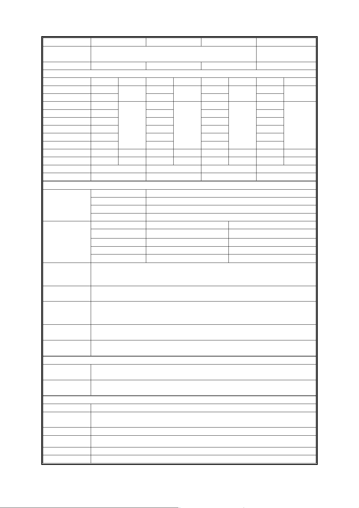
ENERMAX REVOLUTION85+ Series Power Supply Specification
ERV850EWT ERV950EWT ERV1050EWT ERV1250EGT
AC Input Voltage
115-240VAC, 50-60Hz
(Maximum range: 100-264VAC, 47-63Hz)
220-240VAC,
50-60Hz
AC Input Current 9 – 4.5A 10 – 5A 11 – 5.5A 7.5 – 6A
DC Output
Rated Combined Rated Combined Rated Combined Rated Combined
3.3V 0-25A 0-25A 0-25A 0-25A
5V 0-25A
160W
0-25A
170W
0-25A
170W
0-25A
170W
12V1 0-30A 0-30A 0-30A 0-30A
12V2 0-30A 0-30A 0-30A 0-30A
12V3 0-30A 0-30A 0-30A 0-30A
12V4 0-30A 0-30A 0-30A 0-30A
12V5 0-30A 0-30A 0-30A 0-30A
12V6 0-30A
840W
(70A)
0-30A
948W
(79A)
0-30A
1044W
(87A)
0-30A
1248W
(104A)
-12V 0-0.6A 7.2W 0-0.6A 7.2W 0-0.6A 7.2W 0-0.6A 7.2W
5Vsb 0-5A 25W 0-5A 25W 0-5A 25W 0-5A 25W
Total Power 850W 950W 1050W 1250W
Peak Power 1020W 1140W 1260W 1500W
Protection Circuit
DC Rail OCP trigger range
3.3V 30 – 45A
5V 30 – 45A
Over Current
Protection
12V1/2/3/4/5/6 34 – 45A
DC Rail UVP trigger range OVP trigger range
3.3V 2.0 – 2.4V 3.9 – 4.5V
5V 3.3 – 3.7V 5.7 – 6.5V
12V1/2/3/4/5/6 8.5 – 9.5V 13.3 – 14.5V
(DC)
Under Voltage /
Over Voltage
Protection
-12V -8.5 – -9.5V -13.3 – -14.5V
(AC)
Under Voltage
Protection
Activated when AC input voltage < 70VAC.
Over Power
Protection
Activated when output power > 120 ~160% of rated max load.
Over
Temperature
Protection
Activated when PSU heat sink > 90 ~ 110
o
C.
Short Circuit
Protection
Activated when any DC rails short-circuited.
Surge & Inrush
Protection
Sustain 2KV surge stroke.
Sustain up to 70A inrush current @ 240VAC at cold start.
ENVIRONMENT
Temperature
Operation ambient: 0~50
o
C (for full rated output)
Storage ambient: -40~70
o
C
Humidity
Operation: to 85% relative humidity, non-condensing at 25
o
C
Storage: to 95% relative humidity, non-condensing at 50
o
C
OTHERS
Cooling One 13.5cm two-ball bearing fan, speed auto controlled.
MTBF
> 100,000 hours at 70% of full rated load, 230VAC/50Hz, 25
o
C
(MIL-HDBK-217F standard)
Dimension 150 (w) x 86 (h) x 190 (d) mm
Weight
2.95kg (without modular cables) ±50g
Safety UL/cUL(Level 6), TUV, CCC, GOST, CB, BSMI(850/950W)
EMC CE, FCC, KCC
3
User’s Manual
Dear customer,
Thank you for choosing this ENERMAX REVOLUTION85+ power supply unit (PSU)! Please read
this manual carefully and follow its instructions before installing the PSU.
We would like to draw your attention that a computer required very specific conditions to work best
for you without failing. To avoid failures and to increase lifetime of the system, we suggest that:
Your system is NOT located near a radiator or any other heat producing device
Your system is NOT located near a magnetic device
Your system is NOT located in a moist and/or dusty and/or vibrating environment
Your system is NOT exposed to direct sunshine
Your system is sufficiently cooled by additional fans
If you use AC extension cables, please make sure it can support all connected appliances’
potential peak power draw. Or redistribute other high power consumption equipment, such as
laser printers or monitors to other AC wall outlets. Exceeding the extension cable’s loading
capacity could trigger its circuit breaker and cut off the power.
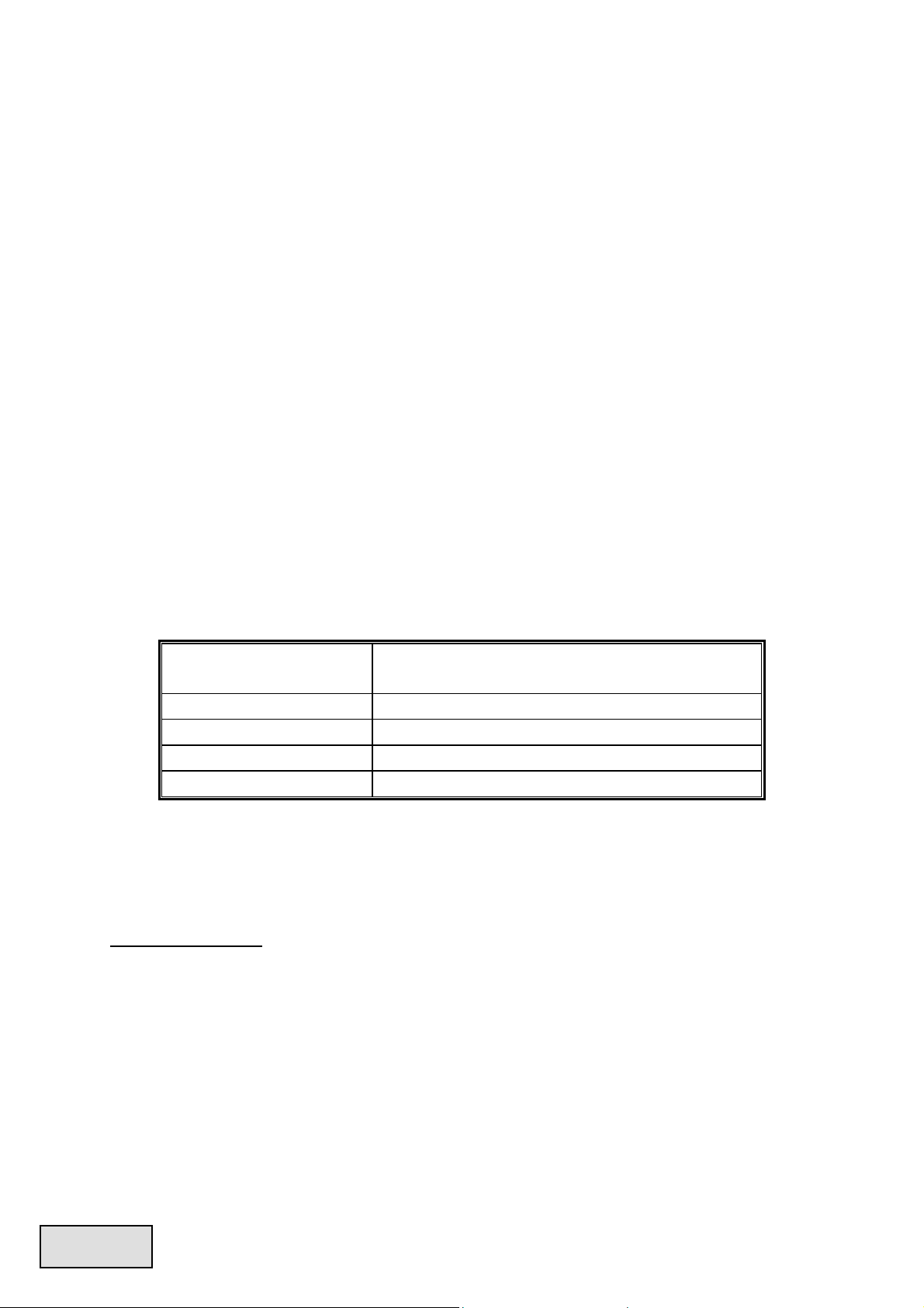
If you want to add the UPS (Uninterruptible Power Supply) for your system, please choose
adequate Watts/VA capacity UPS. Ex.
PSU Model
Suggested minimum UPS output power capacity
(Based on efficiency & PFC at respective load)
ERV850EWT 1000W / 1400VA
ERV950EWT 1100W / 1600VA
ERV1050EWT 1200W / 1700VA
ERV1250EGT 1500W / 2100VA
* If you intend to add other appliance powered by the same UPS, such as monitor or printer,
please use higher capacity UPS according to all connected devices’ rated power draw.
* Please do not mistake VA capacity as Watts, or use insufficient power UPS. This would result
in less UPS battery runtime or the inability to power the system in battery mode.
COMPATIBILITY
ENERMAX REVOLUTION85+ series is compliant with:
SSI PSDG 2008/2009 Power Supply Design Guide specification and downward compatible
with SSI PSDG 2008 v1.0, EPS12V v2.92, v2.91 and v2.8
This PSU does not support MB with ISA expansion slot, which might need -5V power. -5V has
been cancelled from Intel ATX12V v1.3 specification onwards.
ENGLISH
4
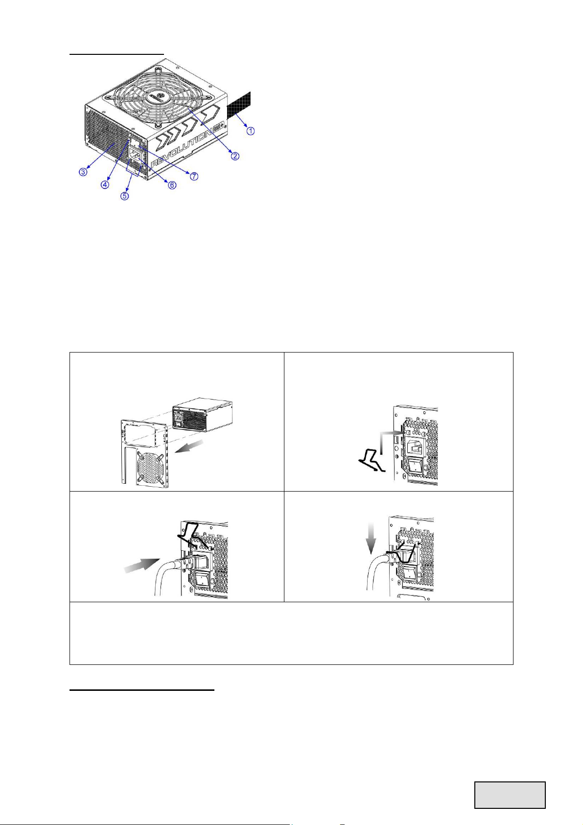
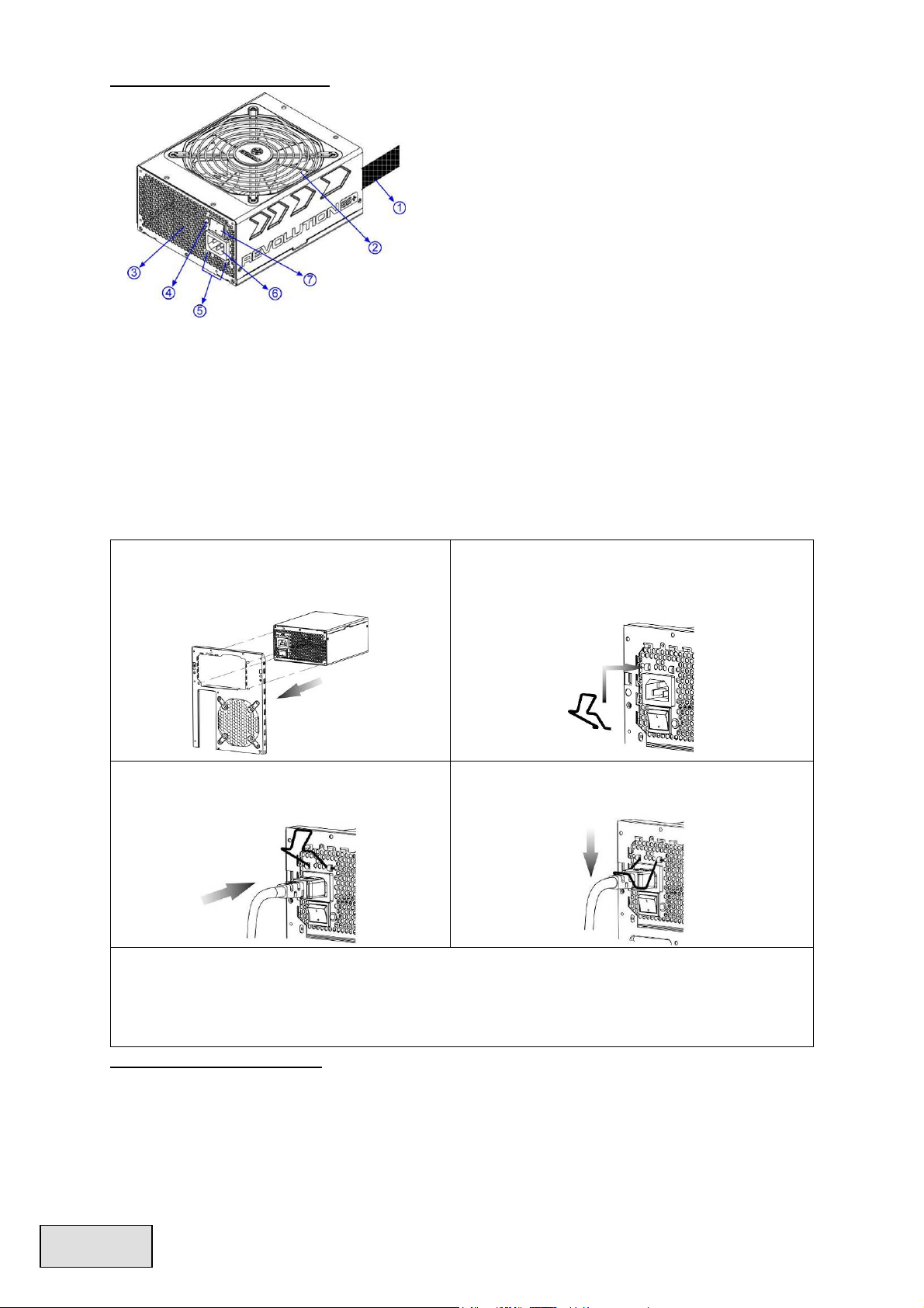
NAME OF PARTS
1Output cable: Please check “Cables & Connectors”
section.
2 13.5cm fan
# 1
3 Honeycomb air vent
# 1
4 PowerGuard LED
5 CordGuard
#3
6 AC Inlet
# 2
7 ON/OFF switch (I=ON, O=OFF)
# 2
#1 To ensure best system cooling, do not block PSU fan’s air in-take and air vent area.
This PSU offers a special HeatGuard function. When the system is turned off, or goes into ACPI
S3/S4 sleep mode, the PSU fan will keep dissipating the remaining heat for 30 ~ 60 seconds and
prolonging system lifetime.
#2 When assembling or maintaining the system, please remove AC cord from AC inlet, or turn
ON/OFF switch into “OFF” position, and wait PowerGuard LED light off. Then you can safely
service the system.
#3 AC cord can get loose in many ways. The ENERMAX CordGuard lock can fix your AC cord
tightly to the PSU, so that it will not be easily detached and avoid shut-downs of your PC. The
following is CordGuard installation:
① Set your PSU into the chassis, and please
make sure the I/O switch is on “O”
position.
② Press two sides of the CordGuard lock
together, and set it into CordGuard holder
near the AC inlet.
③ Plug the AC cord into your PSU.
④ Lock CordGuard to latch onto AC cord.
1. CordGuard is for AC cords supplied with ENERMAX CordGuard-compatible PSUs. Other AC
cords may be incompatible.
2. When assembling or maintaining the system, please remove AC cord from AC inlet, or turn I/O
switch into “O” position.
CABLES & CONNECTORS
All connectors are designed to prevent insertion in wrong orientation. If you cannot easily insert a
connector, please check if you are inserting the connector in the right orientation. Do not try by force
to insert it nor modify the connectors. This might damage power supply and system components, and
warranty shall be void.
ENGLISH

5
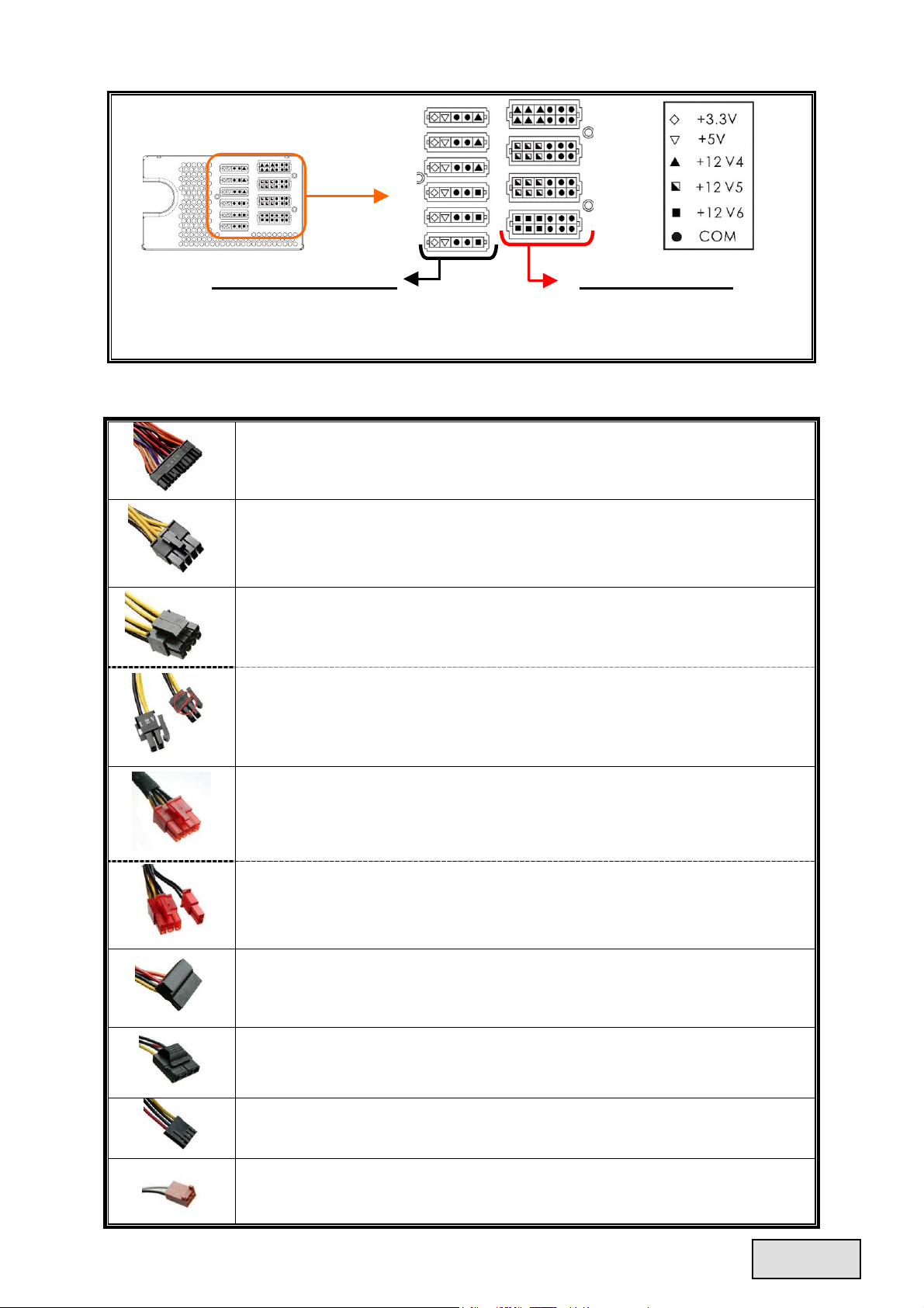
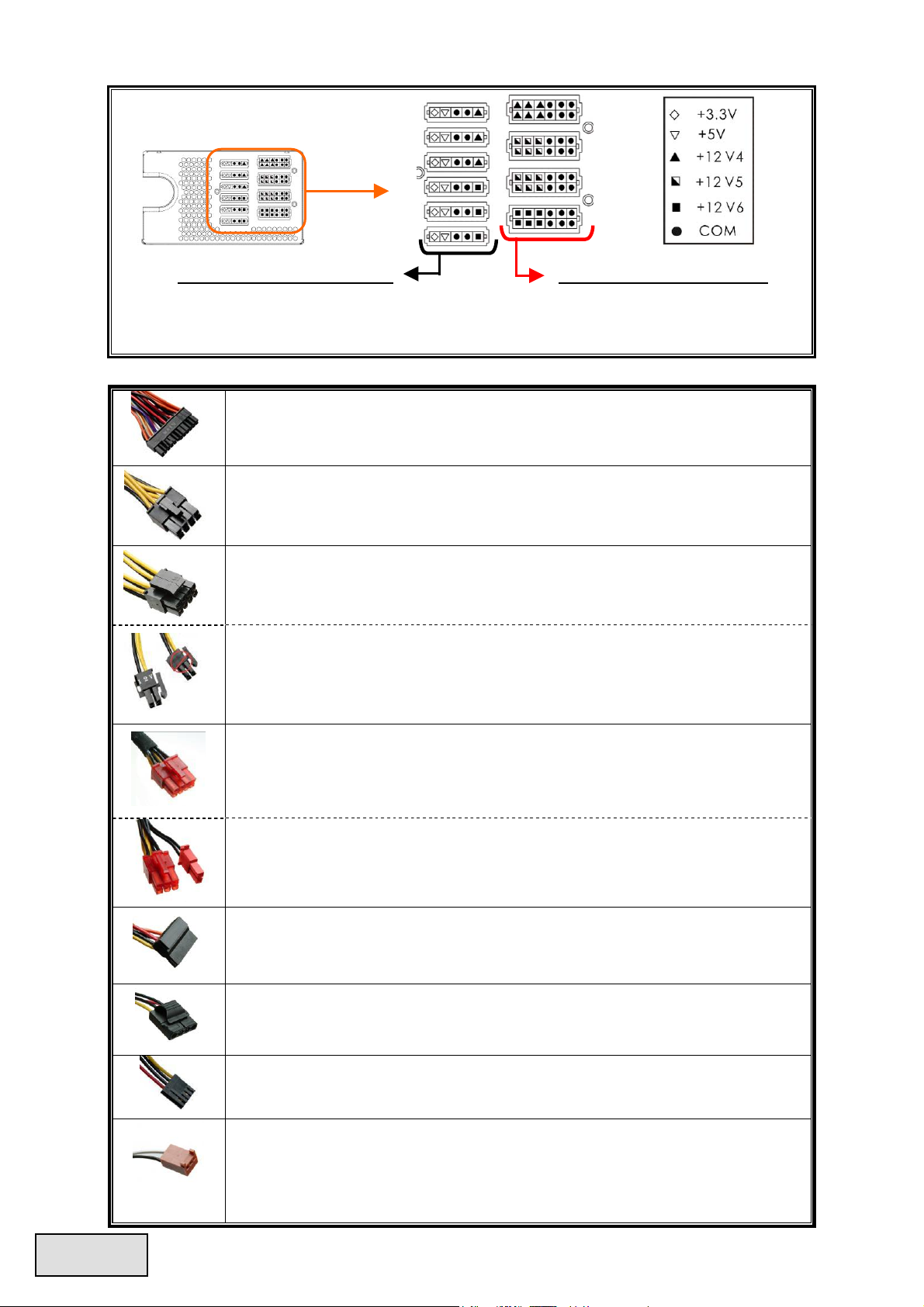
Following graphic illustrates the modular sockets layout and its DC rail distribution.
5P BLACK sockets
The black sockets provide 3.3V/5V/12V for
modular cable to power drives or other
peripheral.
12P RED sockets
The red sockets provide 12V for modular cable
to power graphics card, CPU or RAM.
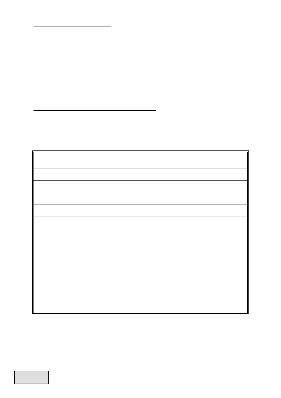
CONNECTOR TYPES
24P Mainboard
Native cable, 12V rail supplied by 12V1
For new generations of ATX/EEB/CEB server/workstation MB.
8P CPU +12V
Native cable, 12V rail supplied by 12V1 & V2
Supports multi-CPU server/workstation systems and some single socket systems.
4+4P (8P) CPU +12V, in combined mode
Native cable, 12V rail supplied by 12V1 & V2
8-pin configuration supports multi-CPU server/workstation systems and some
single extreme CPU systems.
4+4P (8P) CPU +12V, in split mode
Native cable, 12V rail supplied 12V1 & V2
4-pin configuration supports certain single CPU systems. Some multi-CPU
workstation/server system might also need this extra 4-pin 12V connector.
Please use the connector with “12V” marking.
6+2P (8P) PCI Express, in combined mode
Native cable, 12V rail supplied by 12V3
8-pin configuration supports latest extreme graphic cards, which require 8-pin
PCI-E connector.
6+2P (8P) PCI Express, in split mode / 6P PCI Express
Native cable, 12V rail supplied by 12V3
6-pin configuration supports most performance PCI-E graphic cards
, which require
6-pin PCI-E connector.
SATA
# 1
For SATA/SAS drives.
4P Molex
# 2
For IDE/SCSI/SAS drives or some AGP graphic card with traditional 4P power in
socket.
FDD
For floppy drive or certain add-on card.
FM (FAN RPM MONITOR)
# 3
For 13.5cm fan RPM detection.
Fan speed for 850 / 950 / 1050W models: 700-1500RPM (±10%).
Fan speed for 1250W model: 800-1800RPM (±10%).
ENGLISH

6
#1 Some SATA drives might accept SATA or 4P Molex power. Normally, use either one of power
connector to power the driver, BUT NOT BOTH! Please check the drive’s manual for details.
#2 Some MB might require this connector to share the +12V current from 24-pin Mainboard
connector to PCI-E slot. If your MB already supports 24-pin Mainboard connector, you may not
need to add the 4P Molex connector on it. Please check the MB’s manual for details.
#3 Most MB offer 2 ~ 4 3-pin system/PSU fan power sockets, but only one or two socket(s) might
support the fan RPM signal. If you connect the PSU FM connector on the MB, but BIOS or
system monitor software cannot read the PSU fan RPM, please relocate the PSU FM connector to
another socket.
MODULAR CABLES SUPPLIED
Use ONLY genuine ENERMAX modular cables coming with ENERMAX PSU. Third party cables
might not be compatible and might cause damage to your PSU and/or system, and use of third party
cable shall void PSU warranty.
EMC012: 3 x 4P Molex (IDE/SCSI) drives
Modular cable for IDE/SCSI/SAS drives and other peripherals.
EMC013: 3 x 4P Molex (IDE/SCSI) drives & 1 X FDD
connector
Modular cable for IDE/SCSI/SAS drives and peripheral, plus 1
FDD power connector.
EMC014: 2 x 6+2P (8P) PCI-E 2.0
Modular cable for 1 or 2 performance PCI Express graphic cards,
which needs 6P or 8P PCI-E connector.
EMC017: 4 x SATA drives
Modular cable for SATA/SAS drives like ODD and HDD.
EMC018: 8P & 4P +12V CPU/RAM power (optional)
Modular cable to support special heavy-duty workstation/server
with more than 4 CPUs and 16 RAMs.
Supplied modular cables might differ by models and in different region.
We offer more optional cables. Please visit our website for more information:
www.enermax.com
Special note for System Integrators:
If your system requires special modular cable configuration or
design, please contact an ENERMAX sales representative.
ATTACHING / DETACHING THE MODULAR CABLES
Attaching the modular cable to PSU
5-pin / 12-pin connector on modular cable and PSU’s modular socket has an
arrow mark. To make correct connection is easy:
1. Black connector to black socket, and red to red.
2. Arrow mark to arrow mark.
3. Then you can easily plug in the connector.
Detaching the modular cable from PSU
5-pin / 12-pin connector on modular cable has two hooks to lock with the
PSU’s modular sockets. When unplug the modular cable from PSU, please
press two hooks together and gently pull out the cable.
ENGLISH
7
BOOTING YOUR SYSTEM
Before booting your system, please check that:
1. Main power connector (24P) is properly connected.
2. CPU +12V power connector (4 or 8-pin configuration), and/or a 4P Molex connector (if required
by MB) is properly connected.
3. All other needed connectors are properly connected.
4. AC cord is properly connected to wall outlet and PSU AC inlet.
5. Close your system chassis.
6. Turn on the PSU by switching the ON/OFF switch to “ON”, and your system is ready.
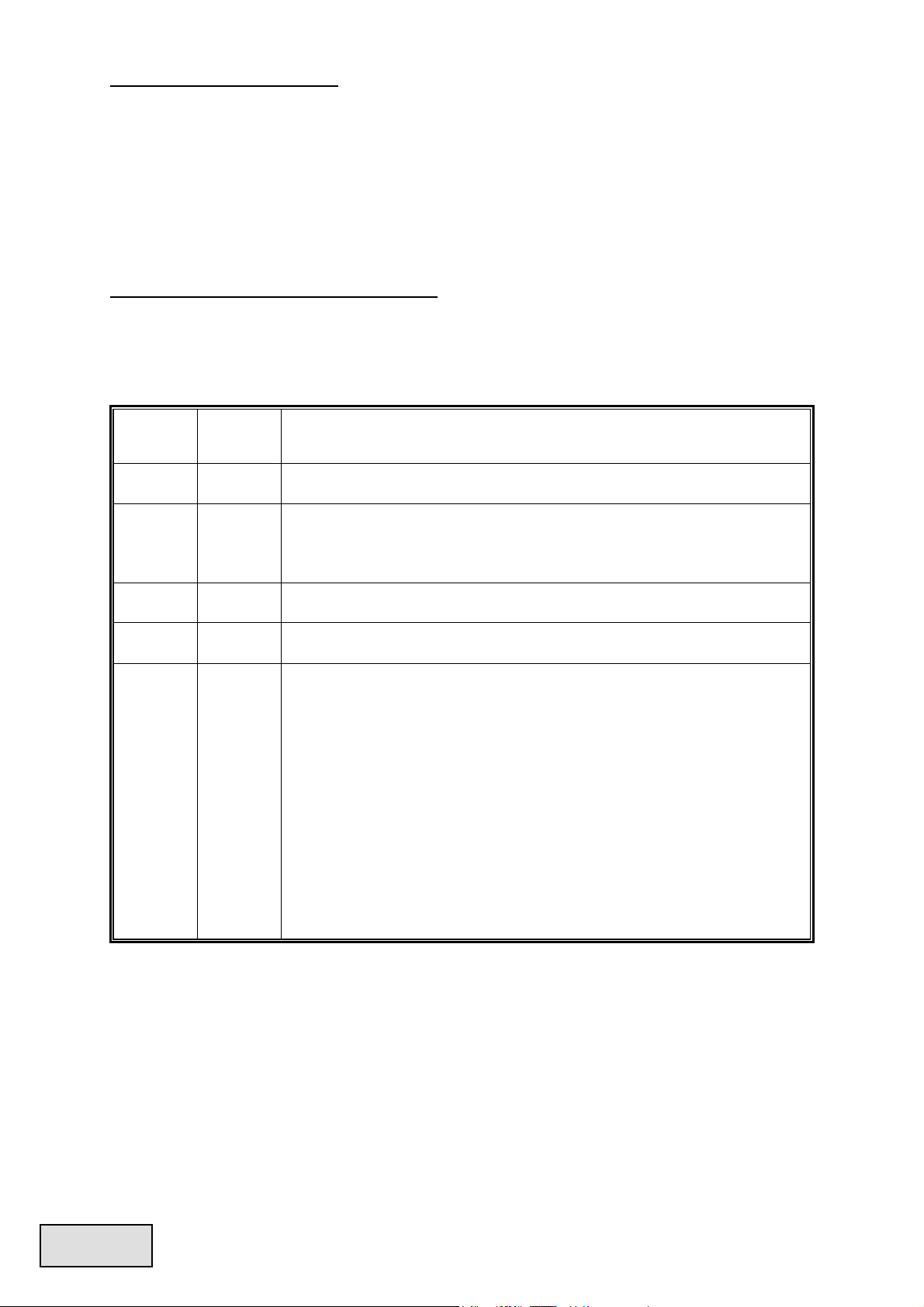
PROTECTION, SAFETY & SECURITY
This PSU features PowerGuard & SafeGuard function to monitor the PSU itself. With tri-color LED,
PowerGuard tells you the current PSU status. In case of abnormal situations, the power supply will
automatically turn off to avoid potential danger to itself and other system components.
PowerGuard indication
LED
ON/OFF
switch
Information & what to do
OFF OFF
* No AC input
- Turn the I/O switch to ON position.
OFF ON
* No AC input or PSU malfunction
- Check if AC cable is firmly plugged into wall outlet and AC inlet. If LED
still does not turn to orange light, then
- Contact ENERMAX service center.
Orange ON
PSU normal and system in standby/ sleep mode
Green ON
PSU normal and system in operation
Red ON
* System abnormal, protection circuit activated.
If you push the system power button, and PSU refuse to turn on, the LED
turn from orange to red light:
- Short-Circuit protection activated.
- Completely check if all connectors are correctly inserted, and clean the
chassis to prevent undesired objects, which might short circuit any
device/terminal.
If during system operation, the PSU suddenly shut down
- Touch the PSU housing and check if it is hot. If yes, wait till it cool
down and restart the system to see if all system fans and PSU fan are
running. Add or replace the system fan if required.
- If same situation repeat, recheck if all connectors are well connected to
system, or redistribute certain drives/PCI-E power to different 12V rail
connector.
If you have any question or need support, please contact your reseller or nearest ENERMAX
subsidiary/agent or ENERMAX headquarter service center.
©2009 ENERMAX Technology Corporation. All rights reserved. Specifications are subject to change without prior notice.
Actual product and accessories may differ from illustrations. Omissions and printing errors excepted. Content of delivery might
differ in different countries or areas. Some trademarks may be claimed as the property of others. Reproduction in any manner
without the written permission of ENERMAX is strictly forbidden.
ENGLISH
8
Benutzerhandbuch
Sehr geehrte Kundin, sehr geehrter Kunde,
Vielen Dank, dass Sie sich für dieses ENERMAX REVOLUTION85+-Netzteil (PSU) entschieden
haben! Bitte lesen Sie sich dieses Handbuch sorgfältig durch und folgen Sie bitte seinen Anweisungen
bevor Sie das Netzteil installieren!
Wir möchten Sie darauf hinweisen, dass moderne Systeme sehr empfindlich geworden sind und genau
definierte Bedingungen benötigen, um optimal ohne Ausfälle arbeiten zu können. Um solche Ausfälle
zu vermeiden und die Lebensdauer Ihres Systems zu verlängern, empfehlen wir Ihnen sicherzustellen,
dass:
Ihr System nicht neben einer Heizung oder einer anderen Wärmequelle steht.
Ihr System nicht neben einer magnetischen Quelle steht.
Ihr System nicht in einer feuchten und/oder staubigen und/oder vibrierenden Umgebung steht.
Ihr System nicht dem direkten Sonnenlicht ausgesetzt ist.
Ihr System ausreichend durch Lüfter gekühlt wird.
Falls Sie ein Verlängerungskabel verwenden, stellen Sie bitte sicher, dass dieses dazu geeignet ist,
den maximalen Strombedarf sämtlicher angeschlossenen Geräte zu leisten. Andernfalls schließen
Sie bitte weitere viel Strom verbrauchende Geräte (wie Laserdrucker oder Monitor) an eine
andere Steckdose an. Ein Überschreiten der maximalen Durchleitungsfähigkeit des
Verlängerungskabels könnte zu einem Auslösen der Sicherung führen.
Falls Sie eine USV (Unterbrechungsfreie Stromversorgung) verwenden möchten, nutzen Sie bitte
eine mit ausreichender Watt/VA-Kapazität. Z. B.:
PSU Modell
Empfohlene kleinste USV-Kapazität
(gemäß Effizienz & PFC bei entsprechender Last)
ERV850EWT 1000W / 1400VA
ERV950EWT 1100W / 1600VA
ERV1050EWT 1200W / 1700VA
ERV1250EGT 1500W / 2100VA
* Falls Sie andere Geräte wie Monitor oder Drucker gleichfalls an die selbige USV anschließen
möchten, wählen Sie bitte eine USV mit höherer Kapazität gemäß der Summe der
Leistungsaufnahme aller angeschlossenen Geräte.
* Bitte verwechseln Sie nicht VA mit Watt und nutzen Sie bitte eine ausreichende USV.
Andernfalls verkürzt sich die Laufzeit der Batterie und gefährdet die Versorgung des Systems
im Batterie-Modus.
KOMPATIBILITÄT
ENERMAX REVOLUTION85+ PSU Serie ist kompatibel mit:
Intel SSI PSDG 2008/2009 Power Supply Design Guide Spezifikation und
abwärtskompatibel mit SSI PSDG 2008 v1.0, EPS12V v2.92, v2.91 and v2.8.
Dieses Netzteil unterstützt keine MB`s mit ISA Erweiterungslots, welche -5V benötigen könnten.
-5V wurde ab Intel ATX12V v1.3 Spezifikation abgeschafft.
DEUTSCH
9
DETAILBESCHREIBUNG
1 Ausgangskabel: Bitte lesen Sie den Abschnitt „Kabel
& Anschlüsse“.
2 13.5cm Lüfter.
# 1
3 Honigwabenluftauslass.
# 1
4 PowerGuard LED
5 CordGuard
# 3
6 Stromeingang
# 2
7 I/O Schalter*: separater Netzteil An/Aus-Schalter
(I=AN, O=AUS).
# 2
#1 Bitte blockieren Sie nicht die Lufteinlässe/Luftauslässe, um eine bestmögliche Systemkühlung zu
gewährleisten. Dieses PSU verfügt über eine besondere HeatGuard-Funktion: Wenn das System
abgeschaltet oder in den ACPI S3/S4 Schlafmodus gebracht wird, wird der PSU-Lüfter die
Restwärme für 30-60 Sek. abführen und so die Lebensdauer des Systems verlängern.
#2 Entfernen Sie immer das Stromkabel vom Netzteil, schalten Sie den I/O-Schalter auf „O“ und
warten Sie, bis die PowerGuard LED erlischt, bevor Sie am System arbeiten.
#3 Der Netzstecker kann sich auf unterschiedliche Weise lösen. Der ENERMAX-CordGuard fixiert
den Stecker am Netzteil. Er verhindert unfreiwillige Systemabstürze durch einen versehentlich
gezogenen Netzstecker.
① Setzen Sie das Netzteil in das Gehäuse ein.
Stellen Sie sicher, dass der Netzschalter auf
“O“ (Aus) steht.
② Drücken Sie die beiden Seiten des CordGuard
zusammen und befestigen Sie ihn an der dafür
vorgesehenen Stelle.
③ Schließen Sie das Netzkabel am Netzteil
an.
④ Klappen Sie den CordGuard herunter und
sichern Sie auf diese Weise den Netzstecker.
1. Der CordGuard ist nur für Netzkabel geeignet, die mit CordGuard-kompatiblen
ENERMAX-Netzteilen ausgeliefert wurden. Andere Netzkabel sind mit dem
ENERMAX-CordGuard ggf. nicht kompatibel.
2. Beim Zusammenbauen oder bei der Wartung des Systems ziehen Sie bitte immer den
Netzstecker oder stellen Sie den Netzschalter auf “O“(Aus).
KABEL & ANSCHLÜSSE
Alle Sockel und Anschlüsse sind so entworfen, dass ein Anschluss in falscher Ausrichtung nahezu
unmöglich ist. Der Anschluss an die kompatiblen Sockel gestaltet sich leichtgängig und ohne größeren
Widerstand. Wenn Sie einen originalen ENERMAX Anschluss nicht auf Anhieb mit einer
Komponente verbinden können, überprüfen Sie bitte, ob Sie die richtige Ausrichtung gewählt haben.
Versuchen Sie es keinesfalls mit Gewalt! Verändern Sie nicht die Anschlüsse! Dies könnte das Netzteil
beschädigen und hat das Erlöschen der Garantie zur Folge!
DEUTSCH
10
Folgende Grafik illustriert das Layout der modularen Sockel und deren DC Leitungsverteilung.
Schwarze 5-Pin Sockel
Schwarze Sockel (3.3V/5V/12V) für modulare
Kabel der Laufwerke (HDD, ODD) oder
Peripheriegeräte.
Rote 12-Pin Sockel
Rote Sockel (12V) für modulare Kabel der
Grafikkarten, CPUs oder RAM.
Anschlusstypen
24P Mainboard
Natives Kabel, 12V Leitung versorgt durch 12V1
Für die neueste Generation von ATX/EEB/CEB Server/Workstation MB’s.
8P CPU +12V
Natives Kabel, 12V Leitung versorgt durch 12V1 & 12V2
Unterstützt Multi-CPU Server/Workstation-Systeme und einige Ein-Sockel
Systeme.
4+4P (8P) CPU +12V, in “kombiniertem Modus”
Natives Kabel, 12V Leitung versorgt durch 12V1 & 12V2
Unterstützt Multi-CPU Server/Workstation-Systeme und einige
Hochleistungs-Einzel-CPU Systeme.
4+4P (8P) CPU +12V, in “getrenntem Modus”
Natives Kabel, 12V Leitung versorgt durch 12V1 & 12V2
4-Pin Konfiguration unterstützt herkömmliche Einzel-CPU Systeme. Einige
Multi-CPU Systeme benötigen möglicherweise ebenfalls diesen Stecker
zusätzlich. Bitte verwenden Sie das Modul mit der „+12V” Markierung.
6+2P (8P) PCI Express, in “kombiniertem Modus”
Natives Kabel, 12V Leitung versorgt durch 12V3
8-pin Konfiguration unterstützt die neuesten Grafikkarten, welche diesen 8-Pin
PCI-E Stecker benötigen.
6+2P (8P) PCI Express, in “getrenntem Modus” / 6P PCI Express
Natives Kabel, 12V Leitung versorgt durch 12V3
6-Pin Konfiguration unterstützt die meisten Grafikkarten, welche diesen 6-Pin
PCI-E Stecker benötigen.
SATA
# 1
Für SATA/SAS-Laufwerke.
4P Molex
# 2
Für IDE/SCSI/SAS-Laufwerke oder einige AGP Grafikkarten mit traditionellem
4-Pin Stecker.
FDD
Für Floppy-Laufwerke oder einige Erweiterungskarten.
FM (FAN RPM MONITOR)
# 3
Geschwindigkeitserfassung für 13.5cm Lüfter
Geschwindigkeit für 850 / 950 / 1050W Modelle: 700-1500 U/min. (±10%).
Geschwindigkeit für 1250W Modell: 800-1800 U/min. (±10%).
DEUTSCH

11
#1 Einige SATA-Laufwerke unterstützen SATA & 4-Pin Molex Stecker. Schließen Sie nur einen
Stecker an! Lesen Sie ansonsten im Handbuch des Laufwerks nach!
#2 Einige MB´s unterstützen diesen Stecker zur zusätzlichen Stromversorgung des 20-Pin
MB-Steckers. Falls Ihr MB einen 24-Pin MB-Sockel besitzt, sollten Sie den 4-Pin Molex Stecker
nicht anschließen. Lesen Sie dies bitte im Handbuch des MB´s nach!
#3 Die meisten MB´s verfügen zwar über zwei bis vier 3-Pin Lüftersockel. Nicht jedes MB unterstützt
jedoch das Lüftertachosignal (FM). Wenn Sie den PSU FM-Stecker an das MB anschließen, aber
ihr BIOS oder Ihre Systemmonitorsoftware das Signal nicht anzeigt, schließen Sie bitte den PSU
FM-Stecker an einen anderen Sockel an.
MODULARE KABEL (im Lieferumfang enthalten)
Benutzen Sie nur original ENERMAX modulare Kabel für dieses PSU. Andere Kabel könnten das
PSU und Ihr System beschädigen und den Garantieverlust zur Folge haben!
EMC012: 3 x 4P Molex (IDE/SCSI)
Modulares Kabel für IDE/SCSI/SAS-Laufwerke und andere
Peripheriegeräte.
EMC013: 3 x 4P Molex (IDE/SCSI) & 1 x FDD
Modulares Kabel für IDE/SCSI/SAS-Laufwerke und
Peripheriegeräte + 1x FDD-Anschluss.
EMC014: 2 x 6+2P (8P) PCI-E 2.0
Modulares Kabel für 1 oder 2 Performance PCI Express
Grafikkarten, welche 6P oder 8P PCI-E Stecker benötigen.
EMC017: 4 x SATA
Modulares Kabel für SATA/SAS-Laufwerke wie ODD und HDD.
EMC018: 8P & 4P +12V CPU/RAM Power (optional)
Modulares Kabel für spezielle Hochleistungsworkstation/Server mit
mehr als 4 CPUs und 16 GB RAM.
Die im Lieferumfang enthaltenen modularen Kabel können je nach Modell und Region
variieren.
Wir bieten weitere optionale Kabel an. Bitte besuchen Sie unsere Webseite:
www.enermax.de
.
Besonderer Hinweis für Systemintegratoren:
Falls Ihr System besondere modulare
Kabelkonfigurationen oder Designs benötigt, sprechen Sie bitte mit einem ENERMAX
Vertriebsbeauftragten.
VERBINDEN & ENTFERNEN VON MODULAREN KABELN
Modulare Kabel an das Netzteil anschließen
Die 5-Pin / 12-Pin Stecker auf den modularen Kabeln und den Sockeln des
Netzteils haben weiße Pfeilmarkierungen.
Folgende Regeln machen die Anwendung einfach:
1. Schwarze Stecker zu schwarzen Sockeln und rote zu roten.
2. Pfeilmarkierung zu Pfeilmarkierung.
Modulare Kabel vom Netzteil entfernen
Alle 5-Pin / 12-Pin Stecker auf den modularen Kabeln haben zwei Haken zum
Einrasten mit den Sockeln des Netzteils. Um ein modulares Kabel zu
entfernen, pressen Sie bitten gegen die zwei Haken und ziehen Sie den Stecker
dann sanft heraus.
DEUTSCH

12
EINSCHALTEN IHRES SYSTEMS
Vor dem Einschalten Ihres Systems stellen Sie bitte sicher, dass:
1. Mainboard-Stromanschluss (24P) korrekt angeschlossen ist.
2. CPU +12V ATX Stromanschluss (4 oder 8 Pin Konfiguration) (falls für MB erforderlich) korrekt
angeschlossen ist, oder ein 4-Pin Molex-Stromanschluss (falls für MB erforderlich) korrekt
angeschlossen ist.
3. Alle anderen erforderlichen Stromanschlüsse korrekt angeschlossen sind.
4. Kaltgerätekabel (Stromkabel) korrekt an Steckdose und Netzteil angeschlossen ist.
5. Das Systemgehäuse verschlossen und verschraubt ist!
6. Drücken Sie am Netzteil den I/O-Schalter auf “I” (ON). Das System ist jetzt bereit!
SICHERHEITSFUNKTIONEN
Dieses PSU verfügt über die PowerGuard & SafeGuard Sicherheitsfunktionen. Die dreifarbige LED
des PowerGuard informiert über den derzeitigen PSU Status. Im Fall der meisten abnormen
Situationen wird sich das Netzteil zum Schutz Ihres gesamten Systems automatisch abschalten, um
Schäden zu vermeiden.
PowerGuard Indikation
LED
AN/AUS
Schalter
Informationen & was ist zu tun?
AUS AUS
* Keine Stromversorgung
- Schalten Sie das PSU mittels I/O-Schalter ein.
AUS AN
* Keine Stromversorgung oder Versagen des PSU
- Prüfen Sie, ob das Stromkabel richtig angeschlossen ist. Falls die LED
noch immer nicht leuchtet, kontaktieren Sie ENERMAX!
ORANGE AN
PSU normal und das System ist im Stand-by/Schlafmodus
GRÜN AN
PSU normal und System im Betrieb
ROT AN
* System abnormal, Sicherheitsfunktion aktiviert.
Falls Sie das System einschalten und das PSU nicht reagiert und sich die LED
von ORANGE zu ROT ändert:
- Kurzschlusssicherung aktiviert
- Prüfen Sie, ob alle Stecker korrekt angeschlossen sind und säubern Sie das
Gehäuse von allen Gegenständen, welche den Kurzschluss verursacht
haben könnten.
Falls während eines normalen Betriebs das PSU plötzlich abschaltet:
- Berühren Sie das Netzteil vorsichtig, um zu prüfen, ob es stark erhitzt ist.
Warten Sie einige Minuten, bis sich das Netzteil abgekühlt hat und starten
Sie dann das System erneut, um zu sehen, ob PSU- und alle Systemlüfter
laufen. Ersetzen oder erweitern Sie diese, falls erforderlich.
- Falls sich das Problem wiederholen sollte, prüfen Sie alle
Steckverbindungen und stecken Sie Stecker am PSU für eine 12V
Lastumverteilung um.
Falls Sie Fragen haben oder Support benötigen, wenden Sie sich bitte an Ihren Händler, Ihre nächste
ENERMAX-Niederlassung, deren Agenten oder an das ENERMAX Headquarter Service Center!
Schnelle Hilfe bei allen Fragen zu ENERMAX-Produkten erhalten Sie auch online im internationalen
ENERMAX-Support-Forum: http://forum.enermax.com.
Die Informationen in diesem Dokument unterliegen unangekündigten Änderungen.
©2009 ENERMAX Technology Corporation. Alle Rechte vorbehalten.
Die Vervielfältigung dieses Dokuments in jeglicher Form ist ohne schriftliche Genehmigung durch ENERMAX streng
untersagt.
DEUTSCH
13
Manual Del Usuario
Estimado cliente:
Muchas gracias por comprar nuestra fuente ENERMAX REVOLUTION85+. Le recomendamos que
se lea bien este manual para el usuario.
Queremos recordarle que los ordenadores actuales son muy vulnerables y necesitan condiciones
especiales para funcionar sin problemas. Para evitar dichos fallos y maximizar la duración del sistema,
le recomendamos que se asegure de:
Su ordenador no se encuentre al lado de la calefacción ni otro objeto que irradie calor
Su ordenador no se encuentre al lado de un objeto magnético
Su ordenador no se encuentre en un entorno húmedo, con polvo y vibraciones
Su ordenador no reciba radiación solar directa
Su ordenador sea refrigerado lo suficiente por parte de los ventiladores
Si utiliza un cable prolongador no lo puede utilizar con otros equipos de alto consumo de
corriente, como impresoras LASER para asegurarse de que no sobrepasa la corriente máxima del
cable, o conecte los equipos a otra toma de corriente.
Si utiliza un SAI (Sistemas de Alimentación Ininterrumpida) para su sistema, debe emplear uno
con capacidad de vatios-VA suficiente como:
modelo de la fuente
Capacidad recomendada mínima del SAI:
(se basa por eficiencia y PFC a carga respectiva)
ERV850EWT 1000W / 1400VA
ERV950EWT 1100W / 1600VA
ERV1050EWT 1200W / 1700VA
ERV1250EGT 1500W / 2100VA
* Si quiere enchufar otros equipos como una impreasora o monitor, tiene que usar un modelo
con capacidad mayor.
* Por favor, no confunda capacidad de VA con vatios ni utilice un SAI insuficiente, ya que
provocaría una disminución de la duración SAI o problemas el encender el sistema en
modalidad de batería.
COMPATIBILIDAD
La serie ENERMAX REVOLUTION85+ fuente es compatible con:
SSI PSDG 2008/2009 Power Supply Design Guide especificación y también con las
versiones PSDG 2008 v1.0, EPS12V v2.92, v2.91 and v2.8.
Si su Tarjeta Madre (MB) utiliza un bus “ISA“, es posible que esta fuente no sea compatible,
porque no tiene una transmisión de -5V, requerida por algunos equipos de ISA. La transmisión de
-5V fue discontinua por Intel ATX12V v1.3!
ESPAÑOL

14
NOMENCLATURA DE LAS PARTES
1 Cable del corriente: Por favor, examine el párrafo
„CABLES Y ENCHUFES”.
2 Ventilador de 13.5 cm.
# 1
3 Honeycomb air vent.
# 1
4 PowerGuard luz
5 CordGuard
# 3
6 Toma de corriente
# 2
7 Interruptor I/O*: separado interruptor de la fuente
por En/Paro (I=En, O=Paro).
# 2
#1 Para asegurar la mejor refrigeración del sistema., no obstruye la ventilación de la fuente. Esta
fuente se ofrece una función especial “HeatGuard”.Cuando el sistema esta apagado o está en modo
ACPI S3/S4, el ventilador de la fuente va a desviar el calor hacia fuera durante 30-60 segundos
para bajar la temperatura media del sistema en unos 3-5
o
C.
#2 Cuando construya el sistema ponga el interruptor en posición “Paro/O” y desenchufe la toma de la
corriente y espere hasta que el LED del PowerGuard se haya apagado. Ahora puede mantener el
sistema de forma segura.
#3 El cable de Alimentación puede ser desconectado accidentalmente de la fuente de alimentación
ocasionando apagados sin aviso y daños en el PC, Enermax dispone de la tecnología CordGuard
manteniendo el conector en su posición correcta y evitando accidentes fortuitos.
① Alojando dentro de la misma fuente el
propio conector y así se asegura que el
conector sae mantiene en la posición correcta.
② Apretando al mismo tiempo las dos solapas de
CordGuard e insertandolos en los huecos donde se
aloja el cable de alimentación.
③ Conectar el cable a la fuente.
④ Se cierra CordGuard haciendo presión.
Esto permite tener siempre en la posición correcta
el dispositivo.
1. CordGuard es un sistema exclusivo de la marca ENERMAX, cualquier intento de instalación en
otro dispositivo distinto puede ocasionar problemas.
2. Cuando se hace mantenimiento del sistema con operaciones internas, el cable SIEMPRE debe
permanecer desconectado.
CABLES Y ENCHUFES
Todos los enchufes están diseñados para que sea imposible conectar cables en la dirección equivocada.
Poner un enchufe en un zócalo tiene que ser fácil. Si no puede poner fácilmente el cableado modular
original de ENERMAX en un zócalo, por favor, revise si está insertado en la dirección correcta. Nunca
lo intente utilizando fuerza ni cambie los pines del voltaje. Eso puede dañar la fuente e invalidar la
garantía.
ESPAÑOL
15
Ilustración gráfica de los zócalos modulares y la distribución c.c..
Zócalos negros de 5 Pines
Los zócalos negros son para cables modulares en
discos (HDD, ODD) o periféricos de
3.3V/5V/12V.
Zócalos rojos de 12 Pines
Los zócalos rojos son para cables modulares
de tarjetas graficas o CPU o RAM de 12V.
TIPOS DE ENCHUFES
24P placas base
Cable nativo, 12V salida por 12V1
Soporta generaciones nuevas de ATX/EEB/CEB server/workstation.
8P CPU +12V
Cable nativo, 12V salida por 12V1 & 12V2
Soporta multi-CPU server/workstation y algunos sistemas single-socket.
4+4P CPU +12V, en “modo combinado”
Cable nativo, 12V salida por 12V1 & 12V2
La configuración 8-Pin soporta multi-CPU server/workstation y algunos sistemas
single-socket extremas.
4+4P CPU +12V, en “modo separado”
Cable nativo, 12V salida por 12V1 & 12V2
La configuración 4-Pin soporta la mayoría de los sistemas single-socket. Unos
sistemas multi-CPU server/workstation posiblemente necesitan este enchufe de
4-Pin 12V. Use el enchufe parcial marcado con “+12V”.
6+2P (8P) PCI Express, en “modo combinado”
Cable nativo, 12V salida por 12V3
La configuración 8-pin soporta las nuevas tarjetas gráficas, que necesitan este
enchufe de 8-Pin PCI-E.
6+2P (8P) PCI Express, en “modo separado” / 6P PCI Express
Cable nativo, 12V salida por 12V3
La configuración 6-pin soporta la mayoría de las tarjetas gráficas, que necesitan
este enchufe de 6-Pin PCI-E.
SATA
# 1
Para ODD o HDD tipo SATA/SAS.
4P Molex
# 2
Para ODD tipo IDE/SCSI/SAS de ”vieja” generación con enchufe 4-P.
FDD
Para discos “Floppy” ó tarjetas de expansión..
FM (FAN RPM MONITOR)
# 3
Para observar la velocidad del ventilador de 13.5 cm. La velocidad normal del
ventilador para REVOLUTION85+ modelos sería
850W / 950W / 1050W: 700-1500RPM (±10%).
1250W: 800-1800RPM (±10%).
ESPAÑOL

16
#1 Unos discos duros de SATA soportan conectores SATA e 4-Pin Molex. Conecte Vd. solamente un
enchufe! Examine su manual para el disco duro para entrar más en detalle.
#2 Unas placas base soportan este enchufe para suministrar corriente addicional aparte del enchufe
24-Pin de la placa base. Si su placa base tiene un zócalo de 24-Pin MB, Vd. no debería conectar
este enchufe de 4-Pin Molex. Debe examinar Vd. su manual sobre la placa base en detalle.
#3 La mayoría de tarjetas madres soportan de dos a cuatro zócalos 3-Pines de ventilación del
sistema/fuente, pero solamente uno o dos soportan el señal de RPM. Sí conecta un enchufe FM de
la fuente a éstos zócalos, pero no hay señal en el BIOS o en su software de monitor, por favor
conéctelo de nuevo a otro zócalo.
CABLES MODULARES (contenido)
Por favor utilice solamente cables modulares originales de ENERMAX. Otros cables podrían dañar el
sistema e invalidar la garantía.
EMC012: 3 x 4P Molex (IDE/SCSI)
Cable modular para ODD o HDD tipo IDE/SCSI/SAS.
EMC013: 3 x 4P Molex (IDE/SCSI) + 1 x FDD
Cable modular para ODD o HDD tipo IDE/SCSI/SAS mas 1x
FDD (Floppy).
EMC014: 2 x 6+2P (8P) PCI-E 2.0
Cable modular para una o dos tarjetas gráficas Performance PCI
Express, que necesitan enchufes de 6 o 8-Pin PCI-E.
EMC017: 4 x SATA
Cable modular para ODD o HDD tipo SATA/SAS de la generación
más reciente.
EMC018: 8P & 4P +12V CPU/RAM power (opcional)
Cable modular para carga alta server/workstation con más que 4
CPU y 16 GB RAM.
Los cables adjuntos podrían diferenciarse por modelo y por región de ventas.
Ofrecemos más cables de forma opcional. Por favor revise nuestra página web para obtener
más información: www.enermax.com
Nota especial para integradores de sistemas:
Si su sistema necesita cables especiales, cables
modulares o con un diseño, contacte a un representante de ENERMAX.
CONECTAR Y EXTRAER CABLES MODULARES
CONECTAR CABLES MODULARES CON LA FUENTE
5-Pin / 12-Pin enchufes de los cables modulares y los zócalos de la fuente
tienen marcas blancas de flecha.
1. Enchufes negros con zócalos negros y rojos con rojos.
2. Flecha con flecha.
3. Ahora puede conectarlo fácilmente.
RENOVAR CABLES MODULARES DE LA FUENTE
Todos los enchufes 5-Pin / 12-Pin de los cables modulares tienen ganchos para
guardar con los zócalos de la fuente. Para quitar un cable modular pulse hacia
las flechas y desconecte el enchufe cuidadosamente.
ESPAÑOL
17
ENCENDIENDO EL SISTEMA
Antes de encenderlo por favor asegúrese de que:
1. El enchufe de la placa base está conectado correctamente.
2. El enchufe del CPU +12V AUX (si es necesario) esté conectado correctamente.
o un enchufe 4-Pin Molex (si es necesario) esté conectado correctamente.
3. Todos los otros enchufes necesarios están conectado correctamente.
4. El cable de la corriente (AC) está conectado correctamente con la fuente y el enchufe!
5. Cierre la caja del sistema!
6. Coloque el interruptor de la fuente en la posición “I”.
FUNCIÓNES DE PROTECCIÓN Y SEGURIDAD
Esta fuente está equipada con la función PowerGuard para monitor el estado de la fuente. Con un luz
de tres colores, le indica el estado de la fuente. En un estado anormal, la fuente se apagará
automáticamente para protegerse ella misma del resto de los otros componentes del sistema.
PowerGuard indicación
LED
EN/PARO
botón
información & que hacer
PARO PARO
* No hay corriente
- Ponga el interruptor en la posición EN..
PARO EN
* No hay corriente o la fuente está dañada.
- Examine, si el cable de corriente esta conectado correctamente. Si no
hay ninguna indicación del LED
- Contacte el centro de servicios de ENERMAX.
NARANJA EN
La fuente está normal y el sistema en modo de espera / sueño.
VERDE EN
La fuente se encuentra en estado normal y el sistema en operación
ROJO EN
* El sistema está mal y se ha activado un circuito de protección.
Si enciende el sistema y la fuente no le da ninguna reacción, pero el LED
se cambia a rojo:
- Se ha activado la protección de corto circuito
- Examine si todos los enchufes están correctamente conectados y
limpie el sistema de objectos extraños, que podrían causar el corto
circuito.
Si la fuente se apaga durante la operación
- Toque la caja de la fuente para examinar si esté caliente. Si lo está,
espere unos minutos para su correcta refrigeración y encienda de
nuevo el sistema para comprobar, si todos las ventiladores están
trabajando. Cambie los ventiladores por unos adicionales.
- Si ocurre de nuevo, compruebe todos los enchufes y conéctelos a otros
zócalos..
Si tiene preguntas o si necesita ayuda, por favor contacte con su vendedor o acuda a una sucursal de
ENERMAX o al centro mundial de soporte de ENERMAX.
La información contenida en este documento está sujeta a cambios sin previo aviso. ©2009 ENERMAX
Technology Corporation. Reservados todos los derechos. Se prohibe estrictamente la reproducción de este
documento en cualquier forma sin permiso en escrito de ENERMAX.
ESPAÑOL
18
Manuel d’utilisateur
Chers clients,
Merci d’avoir choisi l’alimentation ENERMAX REVOLUTION85+! Veuillez lire avec attention ce
manuel avant de procéder à l’installation de l’alimentation.
Nous souhaiterions attirer votre attention sur le fait qu’un ordinateur est fragile, qui demande de
respecter certaines conditions pour fonctionner de façon optimale. Pour éviter tous problèmes et
augmenter la durée de vie de votre système, nous vous suggérons de :
Ne pas placer votre système près d’un radiateur ou de toutes autres sources de chaleur
Ne pas placer votre système près d’une source magnétique
Ne pas placer votre système dans une pièce humide, et/ou salle, et/ou un environnement soumis à
des vibrations
Ne pas exposer votre système à la lumière directe du soleil
Suffisamment refroidir votre système par l’ajout de ventilateurs supplémentaires si nécessaire
Si vous utilisez une rallonge électrique, assurez-vous qu’elle puisse supporter le courant
nécessaire au bon fonctionnement de tous les appareils connectés. Sinon déportez le branchement
des appareils à forte consommation électrique sur une autre prise murale. Si vous dépassez les
capacités de charge maximale supportées par votre câble électrique, vous risquez de couper
l’alimentation.
Si vous souhaitez ajouter un onduleur à votre système, veuillez à choisir la capacité Watts/VA
adéquate. Ex.
Modèle d’alimentation Capacité minimale suggérée pour votre onduleur
ERV850EWT 1000W / 1400VA
ERV950EWT 1100W / 1600VA
ERV1050EWT 1200W / 1700VA
ERV1250EGT 1500W / 2100VA
* Si vous souhaitez brancher plusieurs autres appareils à votre onduleur, comme une imprimante
ou un moniteur, veillez à choisir une capacité en courant plus élevée.
* Assurez vous que les capacités de votre onduleur en watts et VA soient suffisante, sans quoi
votre réserve d’énergie sera fortement réduite ou simplement nulle en cas de coupure de
courant.
COMPATIBILITE
La série ENERMAX REVOLUTION85+ est compatible avec:
Les spécifications SSI PSDG 2008/2009 Power Supply Design Guide et les versions
antérieures SSI PSDG 2008 v1.0, EPS12V v2.92, v2.91 et v2.8
Cette alimentation ne supporte pas les cartes mères avec un slot ISA, qui pourraient demander
une source d’alimentation -5V. Cette dernière a été retirée des spécifications Intel ATX12V v1.3.
FRANCAIS

19
ELEMENTS PRATIQUES
1Câble de sortie: Veuillez vérifier les section
‘‘Câbles & Connecteurs’’.
2 Ventilateur de 13.5cm
# 1
3 Ventilation en Nid d’abeille
# 1
4 LED PowerGuard
5 CordGuard
#3
6 Connecteur AC
# 2
7 Bouton ON/OFF: (I=ON, O=OFF).
# 2
#1 Pour assurer un refroidissement optimal de votre système, veillez à ne pas obstruer les entrées et
sorties d’air de l’alimentation.
Cette alimentation intègre la fonction HeatGuard. Lorsque le système est éteint, ou bien en mode
veille ACPI S3/S4, le ventilateur de l’alimentation continuera à dissiper la chaleur de votre
système pendant 30 à 60 secondes, et prolonger la durée de vie du système.
#2 Lors de l’assemblage ou de la maintenance de votre système, veuillez débrancher le câble
d’alimentation ou bien positionner le bouton sur OFF et attendez que la LED PowerGuard soit
éteinte. Ainsi vous pourrez travailler en toute sécurité.
#3 Le câble d’alimentation peut se décrocher très facilement. Le système ENERMAX CordGuard
permet de fixer le câble d’alimentation sur l’alimentation, rendant la déconnexion quasi
impossible.
① Mettre l’alimentation dans le boîtier, et
vous assurer que le bouton est bien sur la
position”O”.
② Insérer simultanément les deux côtés du
système de fixation CordGuard dans
l’emplacement prévu à cet effet proche du
connecteur d’alimentation.
③ Brancher le câble dans l’alimentation.
④ Refermer le système CordGuard pour
bloquer le câble d’alimentation.
1. CordGuard est compatible avec le câble A.C. fourni avec l’alimentation ENERMAX fonction
CordGuard. Les autres câbles A.C. sont susceptibles d'être incompatibles.
2. Lorsque vous réalisez des manipulations du système, veuillez retirer le câble d’alimentation de
la prise murale ou mettre l’alimentation en position ‘O’.
CABLES & CONNECTEURS
Tous les connecteurs sont étudiés pour éviter une mauvaise insertion. Si vous ne parvenez pas à insérer
facilement un câble dans un connecteur, veuillez vérifier son sens d’insertion. Ne pas forcer ou
modifier les connecteurs. Cela pourrait endommager votre système ou l’alimentation. La garantie sera
annulée.
FRANCAIS
 Loading...