

ENERGY SISTEM T5650 User Manual
User Manual

3
1. INTRODUCTION
To ensure your safety and the safety of others, please ensure that you read all the safety information
before operating this product.
Keep this information in a safe place for future reference.
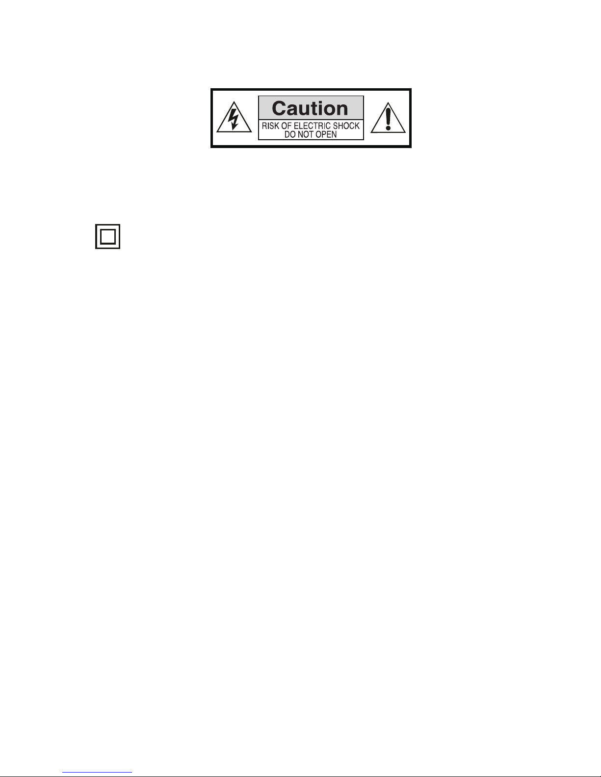
This symbol indicates that this product incorporates double insulation between hazardous
mains voltage and user accessible parts.
WARNING: To reduce the risk of fire or electric shock, do not expose this apparatus to rain or
moisture.
Safety Considerations.
≥ Position the cables so that they cannot be walked on or pinched by items placed on or against
them.
≥ Do not use the set top box in humid or damp conditions.
≥ Do not allow the set top box to get wet.
≥ Do not expose the set top box to dripping or splashing.
≥ Do not place water filled objects such as vases on top of the set top box.
≥ Do not place naked flame sources, such as candles, on the top of the set top box.
Ventilation
The slots and openings on the set top box are for ventilation. Do not cover or block them as it may
cause overheating.
NEVER let children push anything into the holes or slots on the case.
Servicing
There are no user serviceable parts in this set top box.
Battery Disposal
Please ensure batteries are disposed of safely.
Never dispose of batteries in a fire or with other household waste.
Check with your local authority for disposal regulations.
4
Cleaning
ALWAYS unplug the set top box before you clean it.
Do not use liquid or aerosol cleaners.
Clean the set top box with a soft, damp (not wet) cloth.
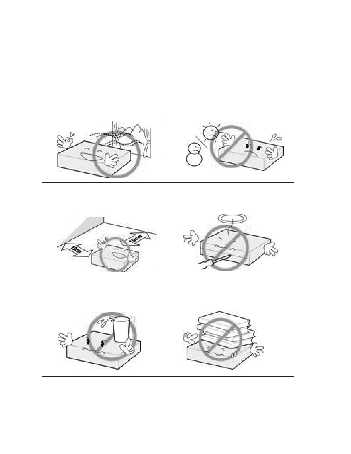
T5650 handling and care
Place the product in a well-ventilated area Don’t install it in the cold or under direct sunlight
Leave a minimum 10cm gap all around the product
Do not disassemble, repair,
or reorganize the product
Don’t place cups with water or other liquids
on the top of the product
Don’t place objects on the top of the product
5
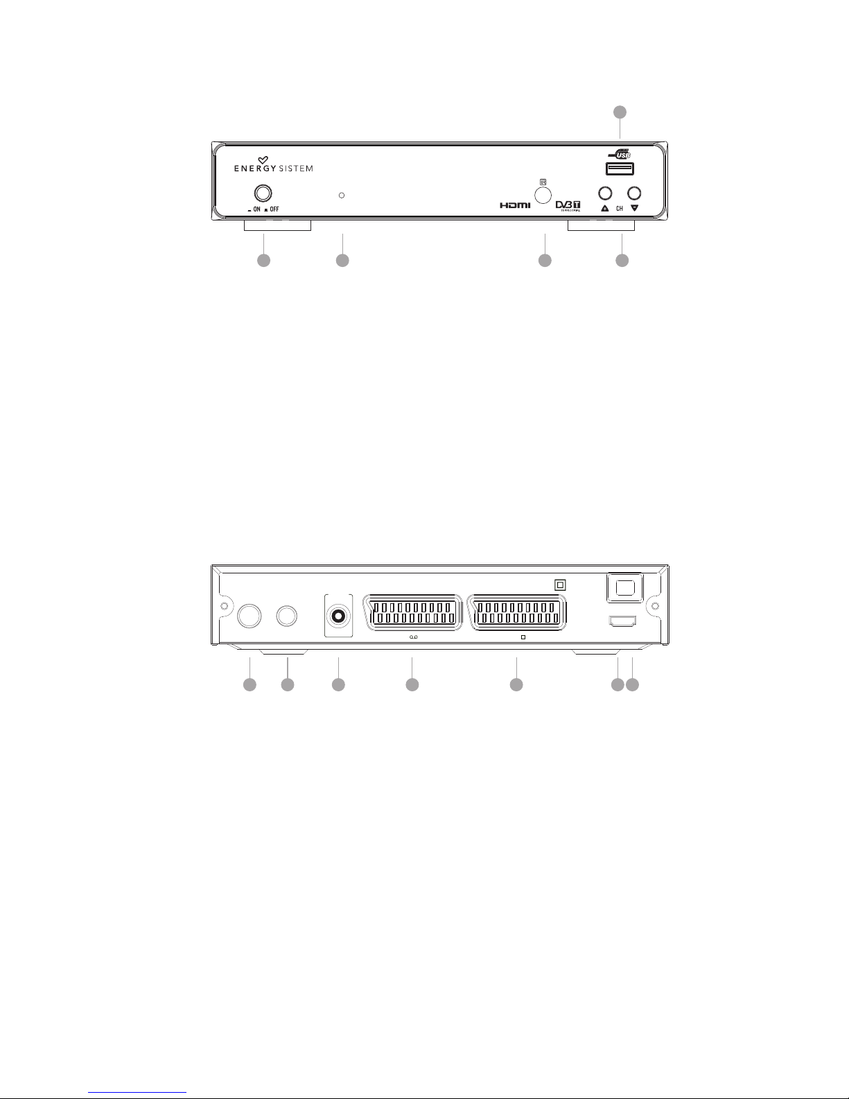
2. FRONT PANEL
1 2 3 4
5
1. POWER: Used to switch the set top box ON or OFF.
2. Standby Indicator: Used to visually show the power state of the set top box:
green LED will show if is turned on the set top box
red LED will be light if the set top box entered standby mode.
3. REMOTE CONTROL SENSOR: Used to receive the signal from the remote control.
4. CHANNEL UP/DOWN: Used to change channels without using the remote control.
5. USB CONNECTOR: Used to attach your external USB hub/card reader/storage device.
3. REAR PANEL
INRF
LOOPRF
THRO UGH
Digi tal
Audi o
HDMI OUTTVVCR
Coax ial
100-240V~
50/60Hz
1 2 3 4 5 6 7
1. RF IN: This socket connects to your external aerial.
2. RF LOOPTHROUGH: This socket will bypass the RF signal to either your TV or another video
system.
3. VCR SCART: This socket connects to either a DVD or other video system.
4. TV SCART: This socket connects to your TV.
5. COAXIAL: This socket connects to a S/PDIF RCA socket on your surround sound system.
6. MAINS CABLE: This is used to connect to your main power supply.
7. HDMI OUT.
6
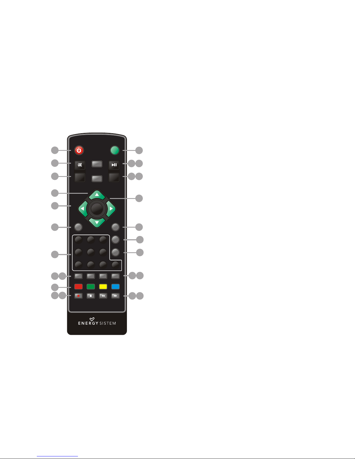
4. REMOTE CONTROL
4.1. BUTTON DESCRIPTIONS
S A D Y
DTV VCR
P Y P US EN O
M T
T N B
/
LA / AI F
U E
EXI T
EPG
CH+
MEN U
V L
+
VOL
-
O
C -
R C ST
RE LL
G M E
A O I E
CA
A
F V R T
H
E LI
AUD IO
TV/ RADI O
SUBTITLE T EXT
STO P
REC ORD
REV
FWD
SLEEP LIST MSM
OK
1 2 3
4 5 6
7 8 9 0
1
13
1514
1716
18
19
20
21
2322
2524
2
3
4
5
6
7
8 9
10
11 12
1. STANDBY: Switch the set top box between on and standby mode.
2. MUTE: Mute/unmute the sound.
3. MENU: Open the main menu window.
4. CH+/-: Move around the menu screens or change the channels in
normal play mode.
5. VOL+/-: Move around the menu screens or change the volume in
normal play mode.
6. RECLIST: Show the recorded programs list.
7. NUMBER KEYS: Select channel numbers or input numbers in
menus.
8. TV/RADIO: Switch between TV channels and Radio stations.
9. AUDIO: Select the available audio track or set the sound mode as
LR(stereo), LL(left), RR(right).
10. COLOR KEYS(RED/GREEN/YELLOW/BLUE): Operate different
functions in TEXT screen or other menus.
RED: SLEEP function (adjustable timer).
GREEN: LIST function.
YELLOW: MSM – Multi Screen Mosaic.
11. RECORD: Record the program manually.
12. STOP: Stop the current recording if exists or stop the playback
and return to DTV mode.
13. DTV/VCR: Switch between VCR SCART input and DTV output
mode.
14. INFO: Display information about the channel being viewed or
further information about the program when in normal play mode.
15. PLAY/PAUSE: Pause or playback the program being viewed.
16. EPG: Display information about the program being viewed and
what’s on next.
17. EXIT: Return to the previous screen or menu.
18. OK: Confirm a selection within a menu.
19. FAVORITE: Access your favourite channels.
20. GAME: Select an accessory: Gomoku, Calendar or Calculator.
21. RECALL: Switch between the last two viewed channels.
22. SUBTITLE: Switch among different subtitles that are broad-
casted.
23. TEX T: Display teletext (if available in the broadcasted stream).
24. REV: Fast backward at selectable speeds.
25. FWD: Fast forward at selectable speeds.
NOTE: SUBTITLES/TEXT/AUDIO may not be available for all channels.
7
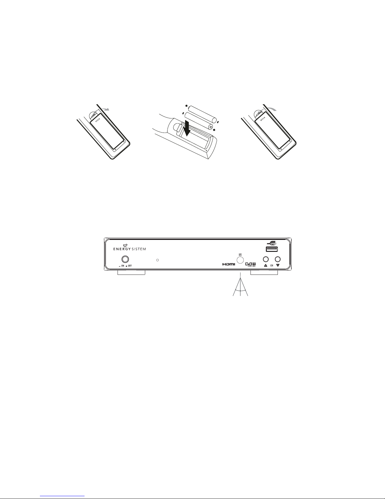
4.2. INSTALLING THE BATTERIES
Remove the battery cover from the remote control and put 2xAAA size batteries inside the
compartment.
The diagram inside the battery compartment shows the correct way to install the batteries.
1. Open the cover 2. Install the batteries 3. Close the cover
4.3. USING THE REMOTE CONTROL
To use the remote control point it towards the front of the digital set top box.
The remote control has a range of up to 7 metres (23 feet) from the set top box at an angle of up to
60 degrees.
30º30º
The remote control will not operate if its path is blocked.
Sunlight or very bright light will decrease the sensitivity of the remote control.
8
5. CONNECTIONS
Caution: Make sure to check that the voltage of the wall outlet has the same rating than the receiver.
To prevent the risk of electric shock, do not open the cover or the back of the receiver.
When connecting the receiver to other equipment (e.g. TV, VCR and amplifier) make sure to refer to
relevant user manual for instruction. Also, make sure you disconnect all the equipments from the
mains supply before the connection.
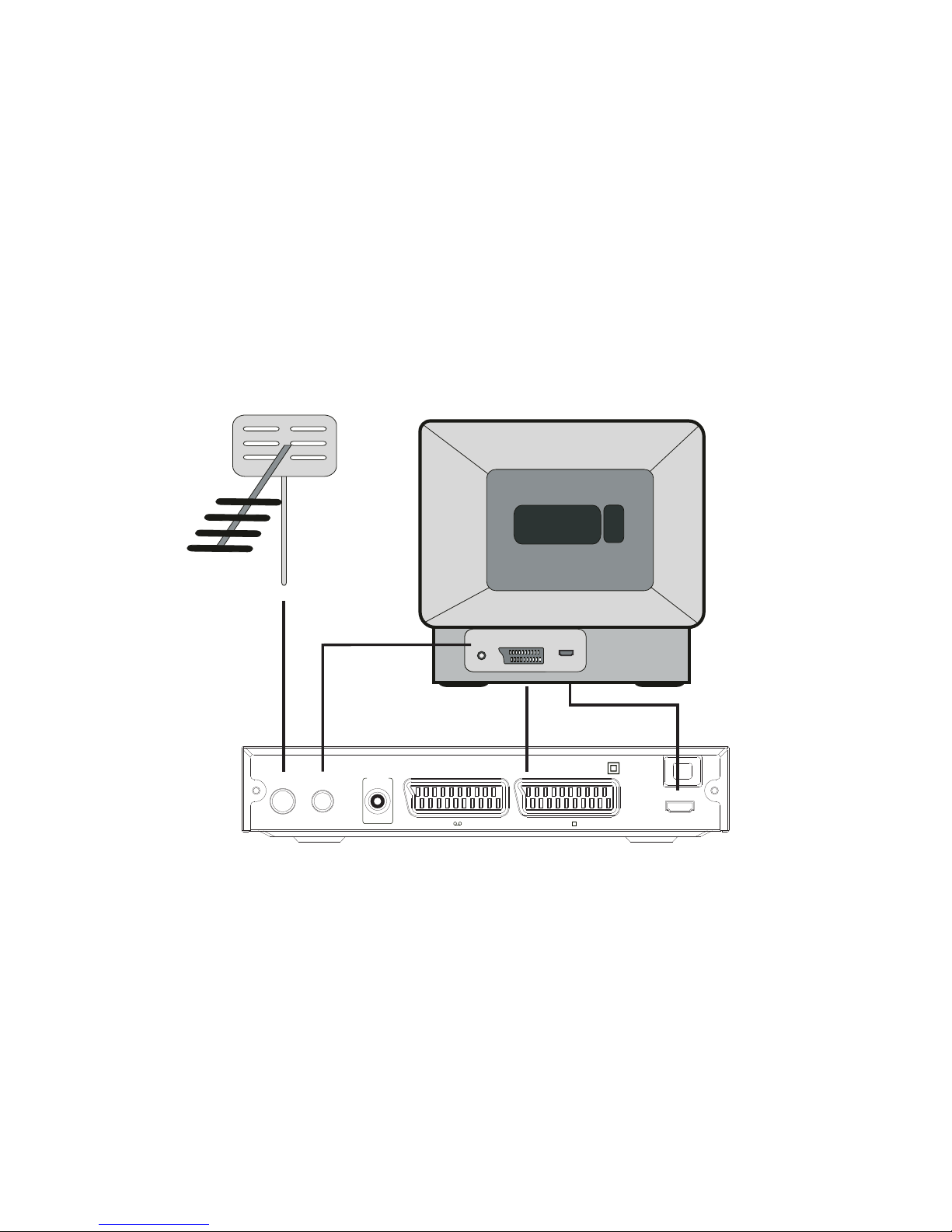
5.1. CONNECTING TO A TV SET
TV
TV aerial
HDMI
RF IN SCART
INR F
LOOPRF
THRO UGH
Digi tal
Audi o
HDMI OUTTVVCR
Coax ial
100-240V~
50/60Hz
9
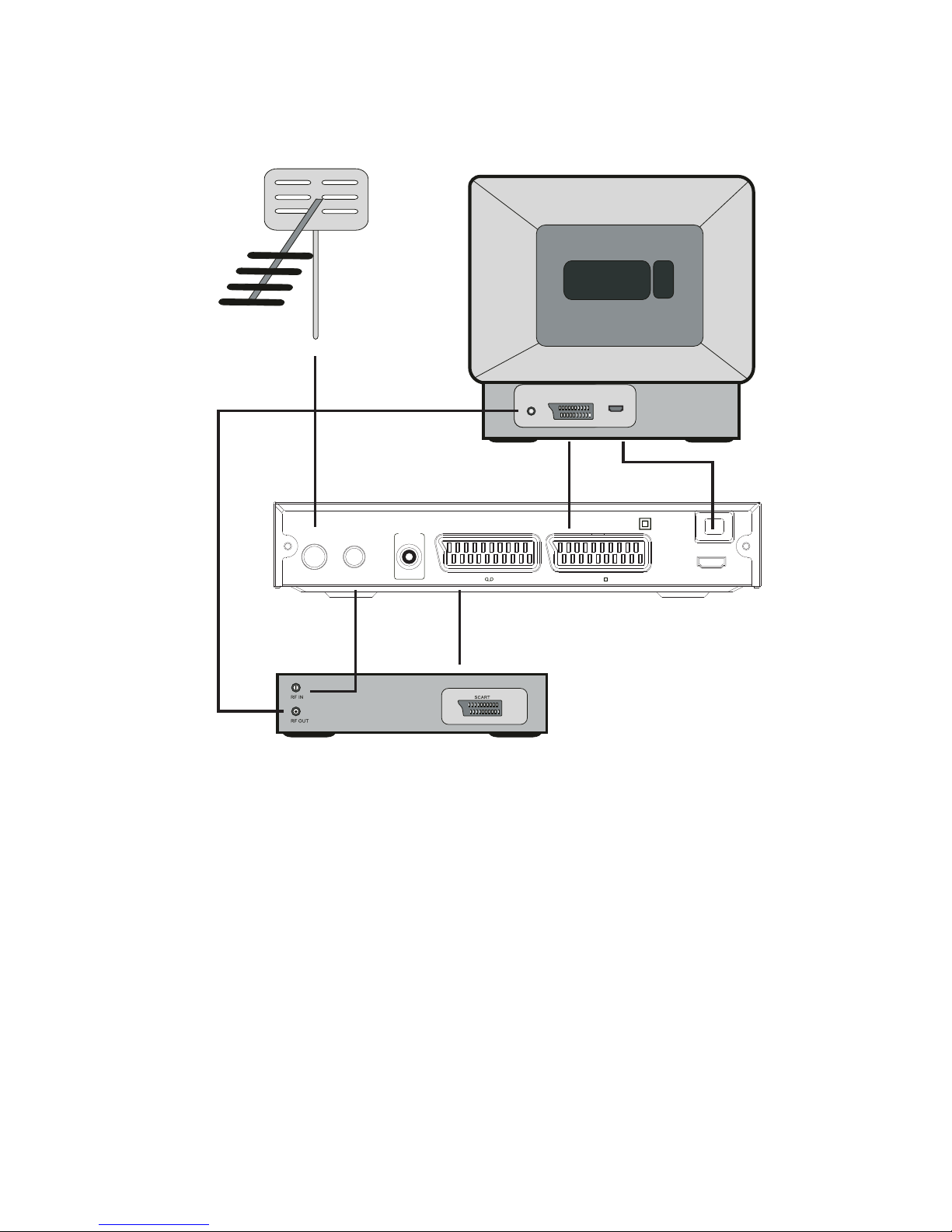
5.2. CONNECTING TO TV AND VCR
TV aerial
TV
VCR
HDMI
RF IN SCART
INR F
LOOPRF
THRO UGH
Digi tal
Audi o
HDMI OUTTVVCR
Coax ial
100-240V~
50/60Hz
10
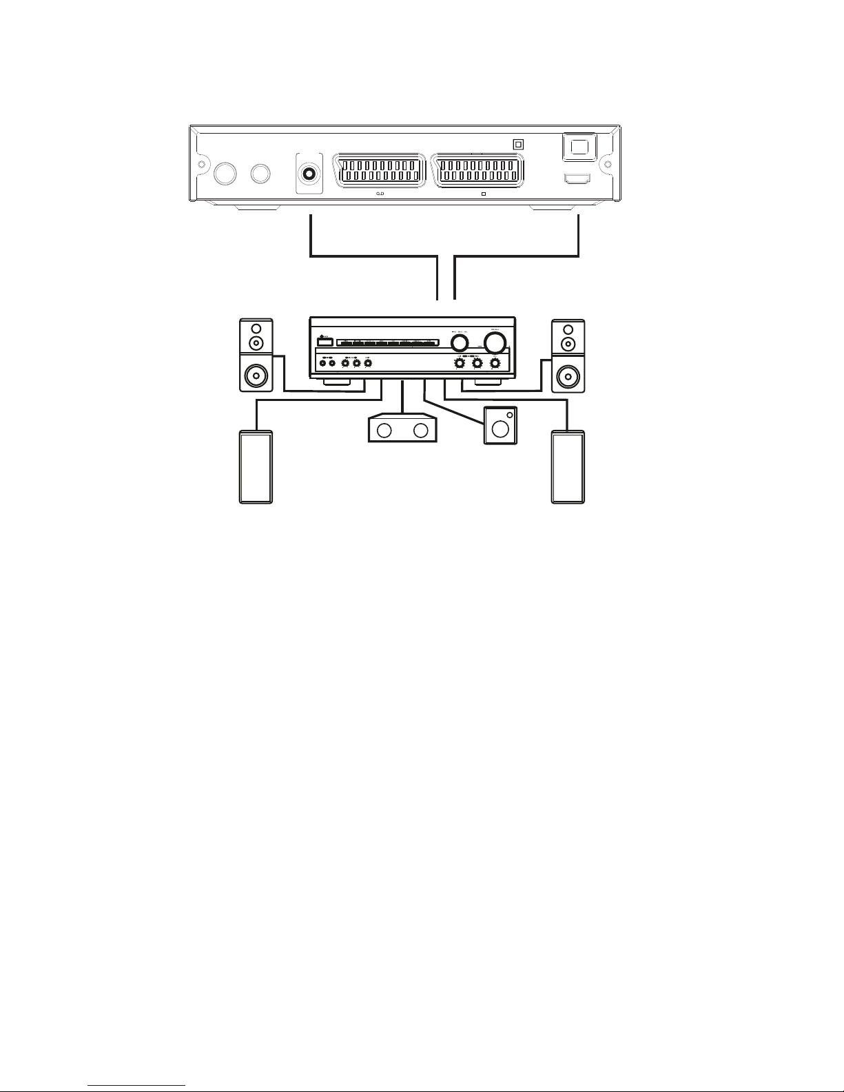
5.3. CONNECTING TO AN A/V RECEIVER WITH DIGITAL AUDIO INPUT
A/V Receiver
INR F
LOOPRF
THRO UGH
Digi tal
Audi o
HDMI OUTTVVCR
Coax ial
100-240V~
50/60Hz
 Loading...