

EnergyLogic MacroAir AVD-370 Installation Manual
Installation
Manual
AVD-370
5901 Crossings Blvd
Antioch, TN 37013
www.energylogic.com
(800) 311-8828

© 2018 EnergyLogic, LLC Toll Free: 800 311 8828 Fax: 615 471 5202 www.energylogic.com 1
Rev. Date 062718
Table of Contents
Caution & Safety ................................................................................................................................. 2
Fusing Chart ....................................................................................................................................... 5
Fan Placement & Clearance .............................................................................................................. 6
Fan Dimensions .................................................................................................................................. 9
Components (Rapid Mount Commercial) .......................................................................................... 10
Components (Fixed Angle Mount) ..................................................................................................... 11
Fan Components & Tools .................................................................................................................. 12
Mounts ................................................................................................................................................ 13
1 - Rapid Mount Commercial
1.1 Rapid Mount Commercial Motor & Extension Tube............................................................ 14
1.2 Rapid Mount Commercial Bolt Kits ..................................................................................... 17
1.2.1 Rapid Mount Commercial Glulam (Direct Mounting) ................................................... 18
1.2.2 Rapid Mount Commercial Glulam (with Glulam Brackets).......................................... 21
1.2.3 Rapid Mount Commercial I-Beam (Steel Truss Mounting) .......................................... 25
1.2.4 Rapid Mount Commercial Unistrut ............................................................................... 29
2 - Fixed Angle Mount
2.1 Fixed Angle Mount Motor & Extension Tube ....................................................................... 32
2.2 Fixed Angle Mount Bolt Kits ................................................................................................. 35
2.2.1 Fixed Angle Mount Glulam ............................................................................................ 36
2.2.2 Fixed Angle Mount I-Beam (Steel Truss Mounting) ..................................................... 39
2.2.3 Fixed Angle Mount Unistrut ........................................................................................... 43
2.3 Guy Wire Installation (Fixed Angle Mount ONLY) ................................................................ 46
3 - Airfoil Installation
3. Airfoil Installation .................................................................................................................. 50
4 - Disconnect Switch
4.1 Fuse Disconnect Switch Installation .................................................................................... 53
4.2 Emergency Disconnect Schematic ...................................................................................... 54
5 - Touchpad Remote Setup
5.1 Touchpad Remote Mounting ................................................................................................ 55
5.2 Touchpad Remote Navigation .............................................................................................. 58
5.2 Touchpad Remote Operations .............................................................................................. 59
Maintenance Information ................................................................................................................... 60
Mounting Plate Dimensions ............................................................................................................... 61
Mounting Bracket Dimensions .......................................................................................................... 62
Touchpad Remote Dimensions .......................................................................................................... 63
Troubleshooting ................................................................................................................................. 64
Warranty and Technical Support ....................................................................................................... 69

© 2018 EnergyLogic, LLC Toll Free: 800 311 8828 Fax: 615 471 5202 www.energylogic.com 2
Rev. Date 062718
Caution & Safety
This appliance can be used by children aged from 8 years
and above and persons with reduced physical, sensory or
mental capabilities or lack of experience and knowledge if
they have been given supervision or instruction concerning
use of the appliance in a safe way and understand the
hazards involved.
Children shall not play with the appliance.
Cleaning and user maintenance shall not be made by
children without supervision.
READ AND SAVE THE ENTIRE MANUAL BEFORE OPERATING THE FAN. Ensure that all safety
practices and instructions are followed during the installation, operation and servicing of the
fan. Failure to apply these safety practices could result in death or serious injury. If you do not
understand the instructions please call EnergyLogic for guidance (contact information can be
found on page 69).
The fan installation should follow the recommendations outlined in this manual. EnergyLogic
is not responsible for any injury or damage to people or property as a result of the user and/or
installer not complying with the recommendations outlined in this manual.
All fan controls and incoming power should only be installed by qualied technicians familiar
with the requirements of the Natural Electric Code (NEC) and local codes. Refer to appropriate
portions of this manual for other important requirements. Failure to follow these guidelines will
void the manufacturer’s warranty.
NOTICE: All electrical controls are congured at the factory and are ready to use. No user
adjustments are available. Follow the included wiring schematics and installation instructions
when installing this device to ensure proper operation. Do not make any changes to any part of
the fan without rst consulting EnergyLogic.
Installation is to be in accordance with the national electrical code, ANSI/NFPA 70-1999 and local
codes.
This appliance is not intended for use by persons (including children) with reduced physical,
sensory or mental capabilities, or lack of experience and knowledge, unless they have been
given supervision or instruction concerning use of the appliance by a person responsible for their
safety.
Children should be supervised to ensure that they do not play with the appliance.
HAZARD OF ELECTRIC SHOCK, EXPLOSION, OR ARC FLASH.
Read and understand this manual before installing or operating a fan unit. Installation,
adjustment, repair, or maintenance must be performed by qualied personnel.
The user is responsible for compliance with all international and National Electrical Code
requirements with respect to the grounding of all equipment.
Many of the parts of this unit operate at live voltage. DO NOT TOUCH.
Install all covers before applying power or starting and stopping the unit.

© 2018 EnergyLogic, LLC Toll Free: 800 311 8828 Fax: 615 471 5202 www.energylogic.com 3
Rev. Date 062718
Caution & Safety
WARNING - TO REDUCE THE RISK OF ELECTRIC SHOCK OR INJURY TO PERSONS, OBSERVE
THE FOLLOWING:
a) Use this unit only in the manner intended by the manufacturer. If you have questions, contact
the manufacturer.
b) Before servicing or cleaning the unit, switch power off at the service panel and lock the service
disconnecting means to prevent power from being switched on accidentally. When the service
disconnecting means cannot be locked, securely fasten a prominent warning device, such as a
tag, to the service panel.
WARNING: If unusual oscillating movement is observed, immediately stop using the ceiling fan
and contact the manufacturer, its service agent or suitably qualied persons.
WARNING: Make sure to power the fan off and lock it out using the IEC/CE approved disconnect
when doing any cleaning and or maintenance to the equipment.
PRIOR TO THE INSTALLATION, ENSURE:
• That the mounting of the suspension system shall be performed by the manufacturer, its
service agent or suitably qualied persons;
• That the fan is to be installed so that the blades are more than 2,3 m above the oor;
• The model or type reference of a luminaire that may be installed in a fan constructed for
this purpose.
DAMAGED EQUIPMENT
Do not operate or install any fans or fan accessories that appear to be damaged. Failure to follow
this instruction can result in death, serious injury, or equipment damage.
SERVICE:
If the fan does not operate properly using the procedures in this manual, BE CERTAIN TO
REMOVE ALL POWER TO THE UNIT and contact our technical department for further assistance.
Keep all body parts clear of moving part at all times. All electrical troubleshooting and repair
must be done by a qualied technician and meet all applicable codes.
Ensure that the replacement of parts of the safety suspension system device shall be performed
by the manufacturer, its service agent or suitably qualied persons.
Key Safety System Components
EnergyLogic fans are engineered with key safety features to prevent pieces of the fan from
falling in the unlikely event of a catastrophic failure. Used together, these features provide
comprehensive protection of people, equipment and property. Follow the detailed instructions
precisely when installing fans, including the following:
• Install the safety cable on EVERY fan. The safety cable, if installed per EnergyLogic
specications, will prevent the fan from falling in the unlikely event that the mounting
system should fail. An EnergyLogic fan should never be run without a properly installed
safety cable, which is supplied with every fan along with all required hardware. You must
install a safety cable for the warranty to be in effect.
• Install guy wires on every fan, unless otherwise specied. Properly installing the guy wires
is required for proper stabilization during normal operation for some fan and mounting
types (Fixed Angle and Universal Mounts). In addition, guy wires keep the fan stable in case
of earthquakes or in “outdoor” installations where high wind conditions may occur.

© 2018 EnergyLogic, LLC Toll Free: 800 311 8828 Fax: 615 471 5202 www.energylogic.com 4
Rev. Date 062718
Caution & Safety
Mark the Floor to Alert Personnel
When mounting a fan in an area where materials may be elevated into its path, EnergyLogic
recommends marking or painting the oor with a large crosshatched circle to alert personnel of
the overhead location of fans.
Weight Considerations
Ensure the xing means for attachment to the ceiling such as hooks or other devices shall be
xed with a sufcient strength to withstand 4 times the weight of the ceiling fan. The maximum
hanging weight for the Model 370 is 79 lbs [36 kg] including the weight of an additional drop
length. If there is any uncertainty in the strength of the building structure, a professional
structural engineer should perform a thorough evaluation of the building prior to purchasing the
fans. EnergyLogic provides guidelines for mounting fans; however, it is the sole responsibility of
the building owner and installer to ensure the safety of the mounting system, that the building
structure is sound and that the installation complies with all federal, state, and local codes.
Torque
The maximum torque (twisting force) during normal operation that must be handled by the
mounting system, including the building structure. For a Model 370, the maximum potential
torque is 20 ft-lbs [27 N-m].
Check Federal, State, and Local Codes
Check all relevant codes to make sure that all product certications, product listings, and
building regulations are met. Code compliance is the responsibility of the installer.
Windy Conditions
Fans should not be operated when wind is present.

© 2018 EnergyLogic, LLC Toll Free: 800 311 8828 Fax: 615 471 5202 www.energylogic.com 5
Rev. Date 062718
Fusing Chart
BRANCH CIRCUIT PROTECTION IS REQUIRED TO PROTECT THE ELECTRICAL COMPONENTS
AND COMPLY WITH UL 507.
Use the table below to select the correct fast acting fuse size for your application. The optional
fuse disconnect switch provided by EnergyLogic uses class CC fast acting fuses. Fuses must be
purchased separately.
Max Amp Draw / Recommended Fuse
Voltage and Phase 6ft 8ft 10ft 12ft
110 VAC 1-Phase 1.5A / 5 5.9A / 7.5 3.8A / 5 2.0A / 5
120 VAC 1-Phase 1.4A / 5 5.4A / 7.5 3.5A / 5 1.8A / 5
208/240 VAC 1-Phase 0.8A / 5 3.1A / 5 2.0A / 5 1.0A / 5
Reference page 53 for installation.

© 2018 EnergyLogic, LLC Toll Free: 800 311 8828 Fax: 615 471 5202 www.energylogic.com 6
Rev. Date 062718
Fan Placement & Clearance
Sprinkler Systems and Fan Placement
In any installation where re sprinklers are in place, fans should not interfere with their correct
operation. Fans should be located no less than 3 feet below a sprinkler, and placed central to
each sprinkler quadrant. Our AirBrain motor controller can be connected to a re suppression
control system which will emergency-stop fans in case of re. Prior to installing fans, review all
codes applicable to sprinkler systems and fans to ensure code compliance (refer to NFPA 13).
Please call EnergyLogic for guidance (contact information can be found on page 69). However, it
is your sole responsibility to see that the installation is completed to code and that it is correct.
Other Information on Placement and Spacing
If possible, avoid mounting fans directly below lights or skylights to avoid any strobe effect
caused by moving airfoils.
If the building has a mezzanine, fans should be mounted so a person cannot reach a fan in any
way from the upper level/deck. Make certain that fans are positioned so that the airfoil tips are at
least 3 feet away from any area where a person may be able to extend outward to reach them.
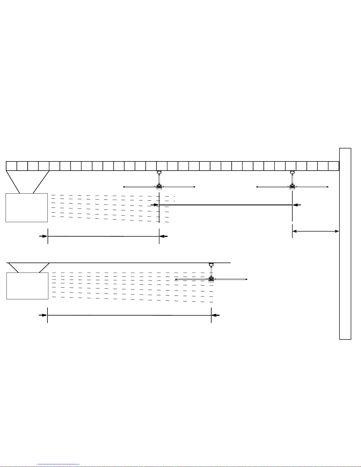
HVLS fans should not be located near to air supply outlets or exhausting inlets of other HVAC
equipment. Supply air outlets can be congured to deliver air away from the HVLS fan or the fan
location should be oriented such that the outlet is pointing away from the fan and outside the
swept area of the fan. Exhaust fan inlets or other return air points creating a negative pressure
should not be within 1.5 times the diameter of the fan. These system will diminish the capacity of
the HVLS fan. Proper systems orientation will provide an enhancement to the Indoor Air Quality
(IAQ) and occupant comfort. Refer to next page for illustration.
© 2018 EnergyLog ic, LLC Toll Fre e: 80 0 311 882 8 Fax: 615 471 52 02 w ww.ener gylogic.com 7
Rev. Date 062718
HVAC Diffuser
with airflow
UNDER fan
HVAC Diffuser
with airflow
ABOVE fan
Fan Placement & Clearance
space from diffuser
space from diffuser
at least 1.5 x diameter away from
intake/discharge
at least 2 x diameter away from intake/discharge
spacing between fans
space from
wall
at least 1.5 x
diameter away
from the wall
at least 3 x diameter of the fans apart
© 2018 EnergyLogic, LLC Toll Free: 800 311 8828 Fax: 615 471 5202 www.energylogic.com 8
Rev. Date 062718
WARNING: FANS ARE NOT MEANT TO BE OPERATED IN WINDY CONDITIONS.
The minimum distance of a fan to a wall or similar obstruction should be no less than 1.5 times
the diameter of the fan.
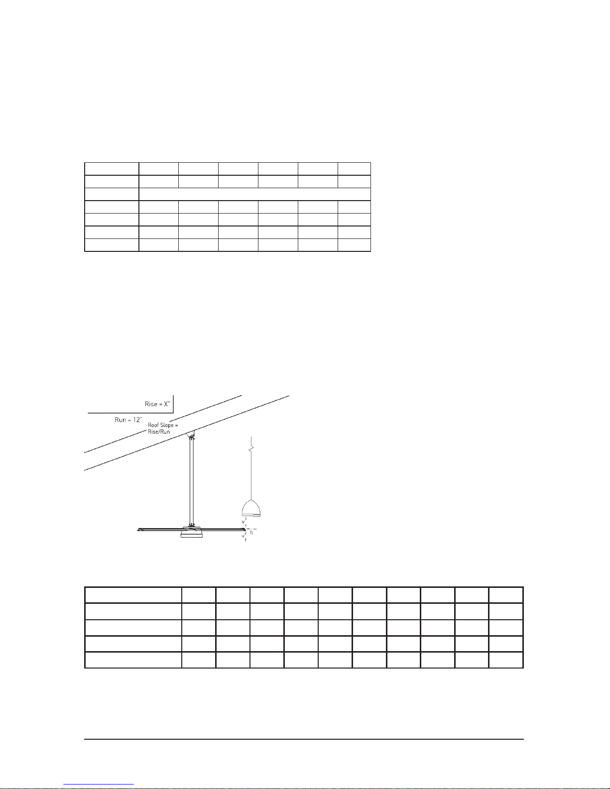
Maximum Angle for Mount (feet)
Slope (in) 0 2/12 4/12 6/12 8/12 10/12
Roof Angle 0 9.5
o
18.4
o
26.6
o
33.7
o
39.8
o
Diameter Recommended Total Drop (Mount to Airfoil) Length (ft)
6 feet 2 2 2 3 4 4
8 feet 2 2 3 3 4 5
10 feet 2 2 3 4 5 6*
12 feet 2 2 3 5 6* 8*
*The Rapid Mount Commercial does not support this angle. Use Fixed Angle Mount for drop
lengths over 5 feet.
The drop lengths above are minimum recommendations only / based solely on roof pitch and fan
diameter. Other factors / such as allowing for proper air ow into the fan must be evaluated when
determining drop length requirements. In addition / EnergyLogic strongly recommends that the
fan airfoils must be a minimum of 10 feet (3.05 meters) above the oor. Contact EnergyLogic for
assistance with fan placement and drop length selection (contact information can be found on
page 69).
The table below shows the clearance
needed from the fan to obstructions such
as lighting / conduit / etc.
Minimum Clearance (Horizontal / Vertical inches):
Airfoil / Drop Length (ft) 1 2 3 4 5 6* 7* 8* 9* 10*
6 feet 7 / 7 7 / 7 7 / 7 8 / 8 9 / 8 8 / 7 9 / 8 10 / 8 12 / 9 14 / 9
8 feet 7 / 7 7 / 7 7 / 8 8 / 8 9 / 9 8 / 8 9 / 8 10 / 9 12 / 10 14 / 10
10 feet 7 / 7 7 / 8 7 / 8 8 / 9 9 / 10 8 / 9 9 / 9 10 / 10 12 / 11 14 / 11
12 feet 7 / 8 7 / 8 7 / 9 8 / 10 9 / 11 8 / 10 9 / 10 10 / 11 12 / 12 14 / 13
Fan Placement & Clearance
needed from the fan to obstructions such
*Drop Lengths over 5 feet require the xed angle mount
© 2018 EnergyLogic, LLC Toll Free: 800 311 8828 Fax: 615 471 5202 www.energylogic.com 9
Rev. Date 062718
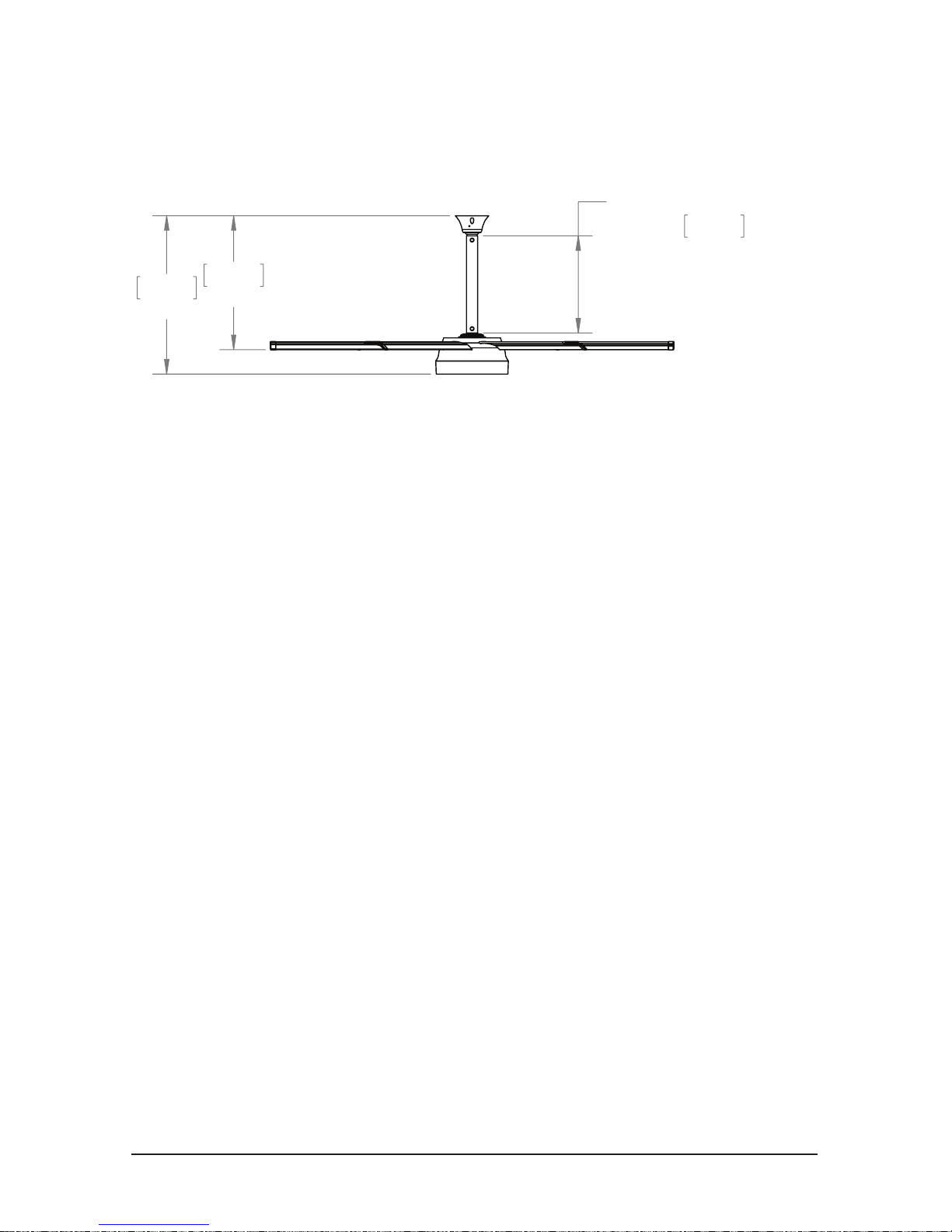
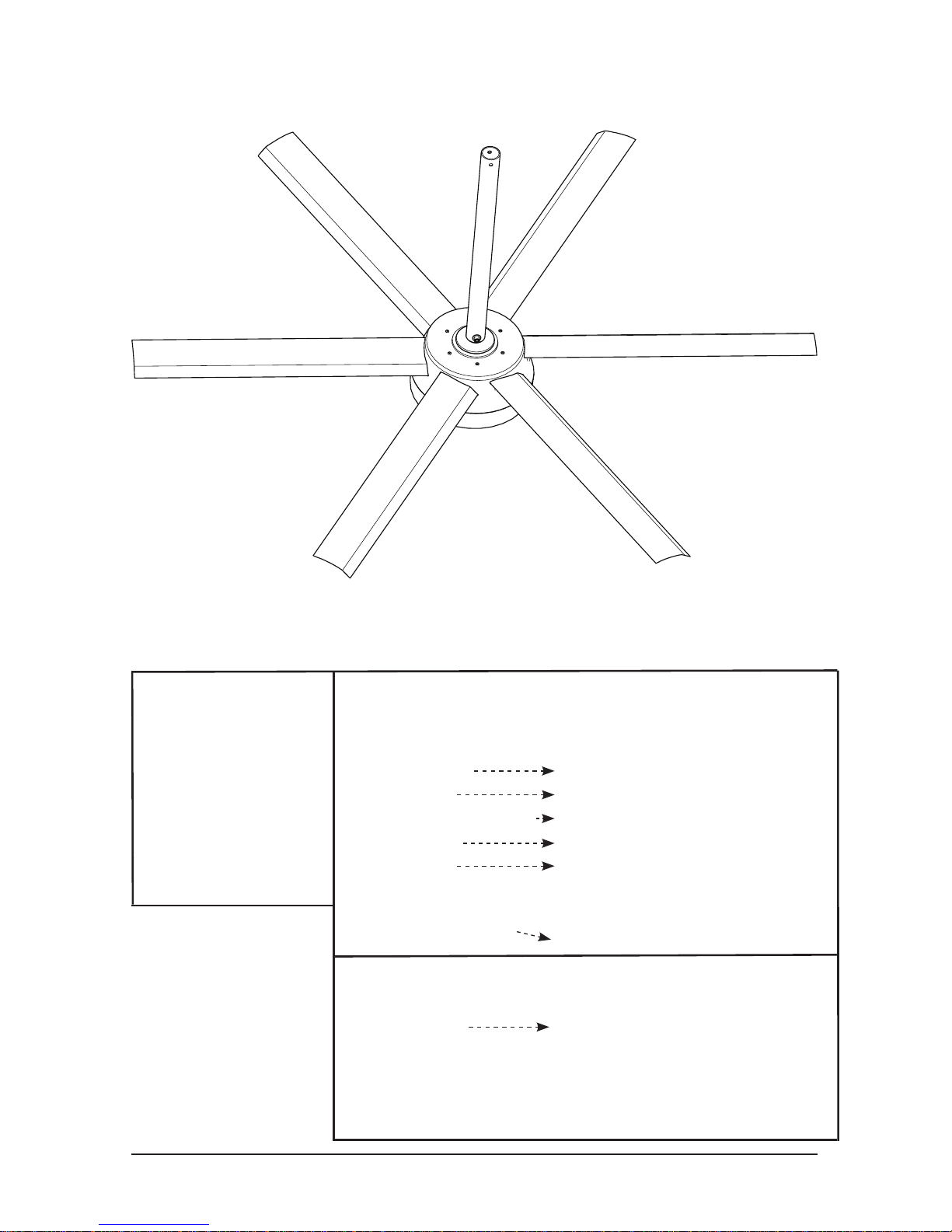
The Model 370 has a standard airfoil to mounting point clearance of 2 feet [0.61 m] with the Rapid
Mount Commercial. Refer to the Fan Clearance & Placement charts on pages 6-8 for required
fan clearance and mounting conditions.
Fan Dimensions
ILLUSTRATION
SHOWN WITH
STANDARD EXTENSION
0.441
1'5.375"
0.609
2'0"
0.720
2'4"
© 2018 EnergyLogic, LLC Toll Free: 800 311 8828 Fax: 615 471 5202 www.energylogic.com 10
Rev. Date 062718
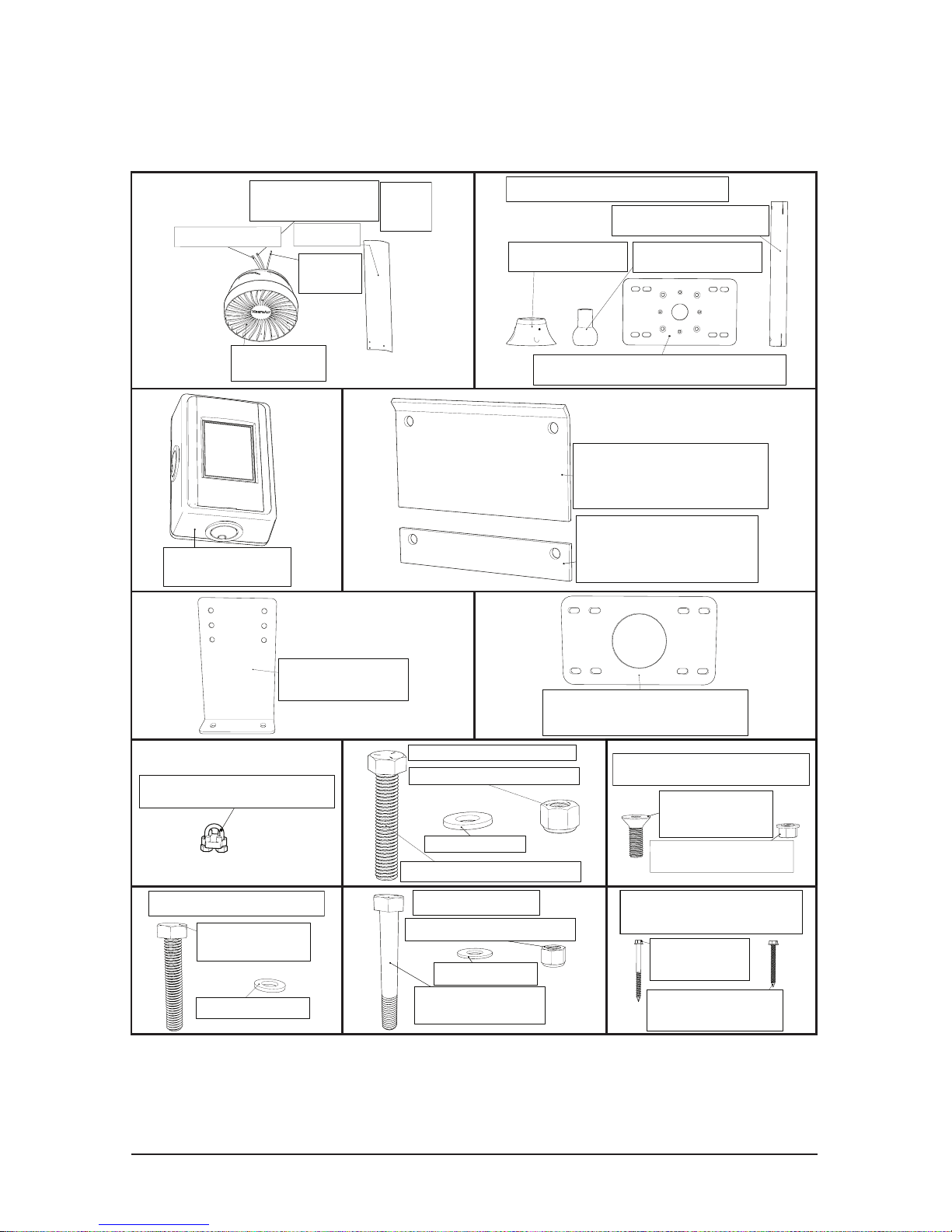
Glulam Bracket (2)
(Optional)
Noise Dampening Pad (1)
(Optional)
Top Mount Plate (1) (Optional)
Extension Tube (1)
Mount Cap (1)
Mount Shaft (1)
Rapid Mount Commercial Parts
Touchpad Digital
Remote (1)
Wire Rope Clamp (2)
M5 x 32mm Hex
Head Bolt (18)
AVD 370 Blade Bolt Kit
M5 Washer (18)
1/2"-13 x 2 1/2" Hex Bolt (4)
1/2"-13 Nylon Lock Nut (4)
1/2" Washer (8)
I-Beam Bolt Kit (Optional)
3/8" Washer (4)
3/8"-16 Nylon Lock Nut (2)
3/8"-16 x 2 3/4" Hex
Head Bolts (2)
3/8" Washer (4)
Extension Bolt Kit
1/4"-28 x 3/4"
Countersunk Socket
Head Cap Screw (4)
1/4"-28 Flanged Distorted
Thread Locknut (4)
Rapid Mount Commercial Mounting
Plate Bolt Kit (Optional)
Components
(Rapid Mount Commercial)
Make sure all parts listed above are included if you purchased the Rapid Mount
Commercial. Read the entire manual before beginning the installation of the
fan. Additional parts may be required, including, but not limited to, guy wire
attachment hardware, extra cable, Unistrut, and bolts for Glulam mounting.
#10 2-1/2"
Lag Screw (4)
#10 1-3/4"
Concrete Screw (4)
Rapid Mount Commerical
Mounting Screws
I-Beam Shim (2)
(Optional)
I-Beam Clamp (2)
(Optional)
AVD 370
Motor Unit (1)
Airfoil (6)
Safety
Cable (1)
Sheilded Stranded
CAT5e Cable (1)
Power Cable (1)
RJ45
Pin-Out
Type “B”
© 2018 EnergyLogic, LLC Toll Free: 800 311 8828 Fax: 615 471 5202 www.energylogic.com 11
Rev. Date 062718
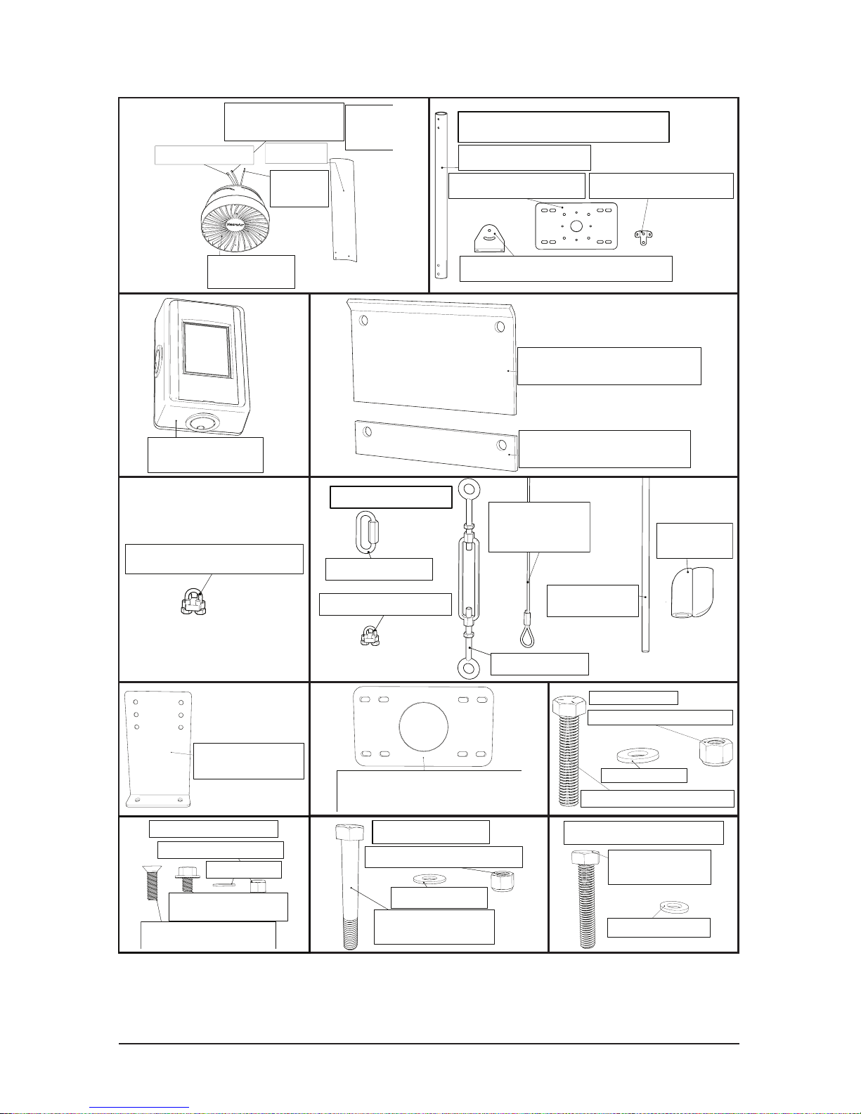
Glulam Bracket (2)
(Optional)
Noise Dampening Pad (1)
(Optional)
Fixed Angle Mount Bracket (2)
Guy Wire Bracket (2)
Top Mount Plate (1)
Extension Tube (1)
Fixed Angle Mount Parts
Wire Rope Clamp (2)
M5 x 32mm Hex
Head Bolt (18)
AVD 370 Blade Bolt Kit
M5 Washer (18)
1/2"-13 x 2 1/2" Hex Bolt (4)
1/2"-13 Nylon Lock Nut (4)
1/2" Washer (8)
I-Beam Bolt Kit
3/8" Washer (4)
3/8"-16 Nylon Lock Nut (2)
3/8"-16 x 2 3/4" Hex
Head Bolts (2)
3/8" Washer (4)
Extension Bolt Kit
3/8" Washer (4)
3/8"-16 x 1 1/4"Countersunk
Socket Head Cap Screw (4)
3/8"-16 Nylon Lock Nut (4)
3/8" Washer (4)
3/8"-16 x 1 1/4"Countersunk
Socket Head Cap Screw (4)
3/8"-16 x 1/2" Serrated
Flange Hex Head bolt (4)
Fixed Angle Mount Bolt Kit
Components (Fixed Angle Mount)
Make sure all parts listed above are included if you purchased the Fixed
Angle Mount. Read the entire manual before beginning the installation of the
fan. Additional parts may be required, including, but not limited to, guy wire
attachment hardware, extra cable, Unistrut, and bolts for Glulam mounting.
Guy Wire Assembly
Wire Rope (4)
19ft (A), 23ft (B),
or 33ft (C)
Turn Buckle (4)
1/4" Quicklink (4)
Wire Rope Clamp (8)
AVD 370
Motor Unit (1)
Airfoil (6)
Safety
Cable (1)
Sheilded Stranded
CAT5e Cable (1)
Power Cable (1)
RJ45
Pin-Out
Type “B”
I-Beam Shim (2)
I-Beam Clamp (2)
Guy Wire
Elastic Band (1)
Elastic Band
Clip (1)
Touchpad Digital
Remote (1)
© 2018 EnergyLogic, LLC Toll Free: 800 311 8828 Fax: 615 471 5202 www.energylogic.com 12
Rev. Date 062718
Fan Components and Tools
Tools Required:
For All Mounts:
-Torque Wrench
-Level
-Phillips Screwdriver
-3/8’’ Wrench
-9/16 Wrench
-5/16’’ Socket
-9/16’’ Socket
For Rapid Mount Commercial:
-Needle Nose Pliers
-Cordless Drill For Glulam Mounting
-1/4” Socket For Direct Glulam Mounting
-3/16’’ Hex Bit Socket For Unistrut Mounting
-3/4’’ Wrench For I-Beam & Glulam Brackets
-3/4’’ Socket For I-Beam & Glulam Brackets
-1/8’’ Allen Wrench (Provided)
-5/32’’ Allen Wrench (Provided)
For I-Beam & Glulam Brackets
For Fixed Angle Mount:
-Cordless Drill For Glulam Mounting Only
-1/2” Wrench
-3/4’’ Wrench
-3/4’’ Socket
-7/32” Allen Wrench (Provided)
© 2018 EnergyLogic, LLC Toll Free: 800 311 8828 Fax: 615 471 5202 www.energylogic.com 13
Rev. Date 062718
If using the Universal Mount, please refer to the AVD 550/780
manual for proper mounting instruction, which can be found at
www.EnergyLogicfans.com/resources/
Mounts
Noise Dampening Pad
Place Noise Dampening
Pad between mount and
mounting surface for all
mounts and mounting styles.
If you purchased the Noise/Vibration Dampening Pad (optional):
Rapid Mount Commercial
Turn to page 14
Fixed Angle Mount
Turn to page 32
© 2018 EnergyLogic, LLC Toll Free: 800 311 8828 Fax: 615 471 5202 www.energylogic.com 14
Rev. Date 062718
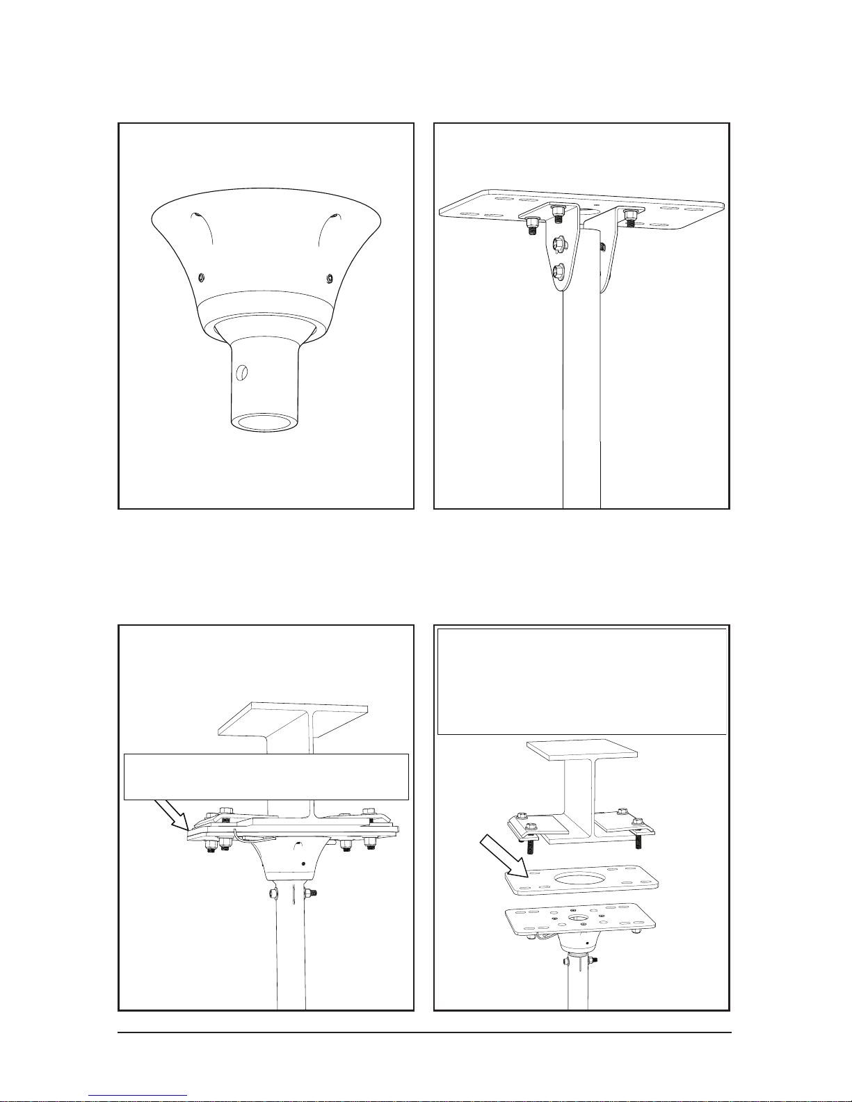
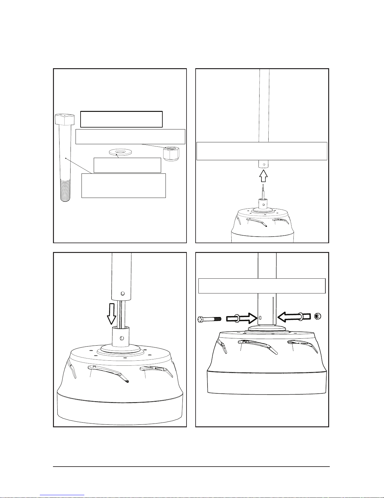
1.1 Rapid Mount Commercial
Motor & Extension Tube
3/8" Washer (4)
3/8"-16 Nylon Lock Nut (2)
3/8"-16 x 2 3/4" Hex
Head Bolts (2)
3/8" Washer (4)
Extension Bolt Kit
Feed cables through tube
Feed cables through tube
Be careful of wires
© 2018 EnergyLogic, LLC Toll Free: 800 311 8828 Fax: 615 471 5202 www.energylogic.com 15
Rev. Date 062718
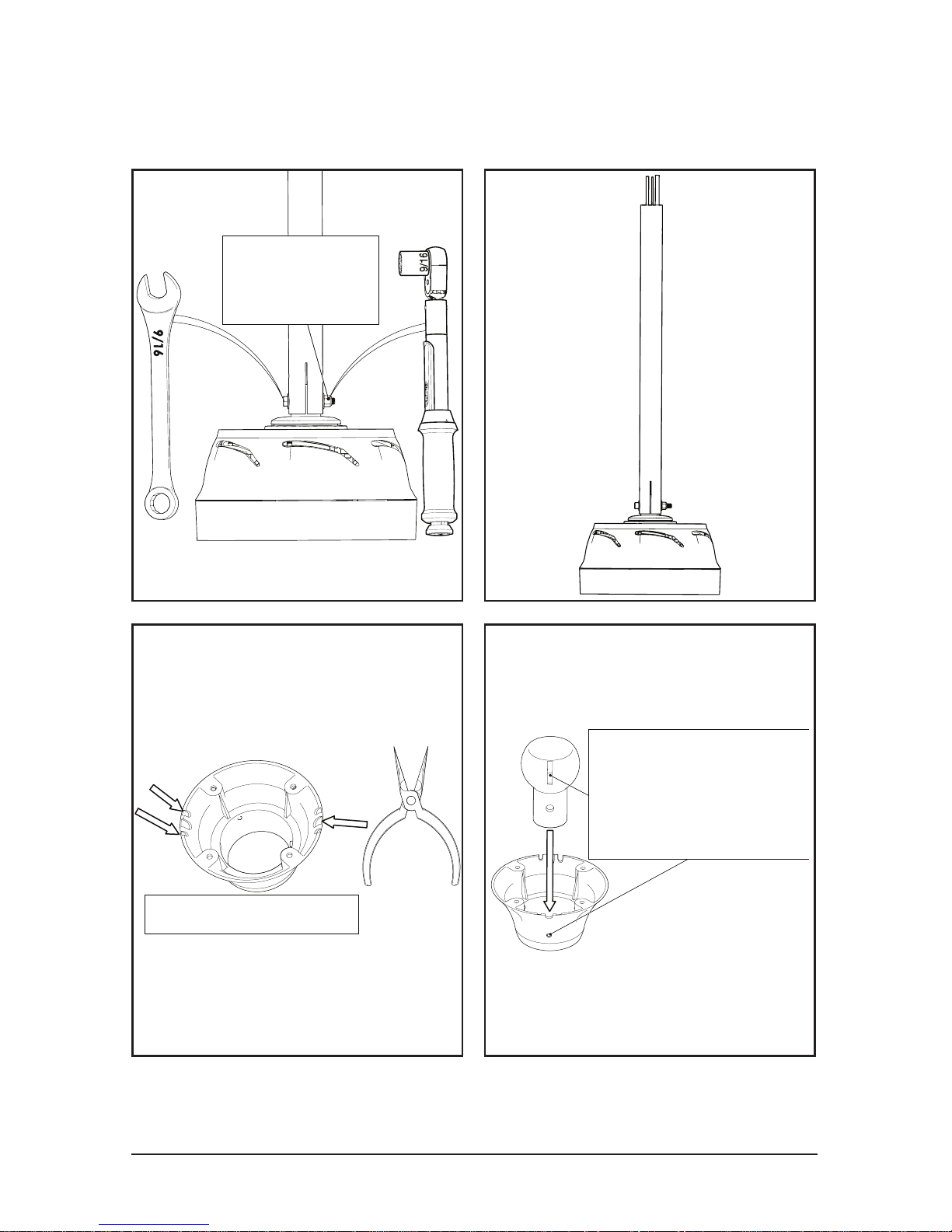
30 ft-lbs
30 ft-lbs
[41 N-m]
9/16”
Remove Breakouts
Line-up pin and
groove to ensure
no rotational
movement
Line-up pin and
groove to ensure
no rotational
movement
1.1 Rapid Mount Commercial
Motor & Extension Tube
© 2018 EnergyLogic, LLC Toll Free: 800 311 8828 Fax: 615 471 5202 www.energylogic.com 16
Rev. Date 062718
30 ft-lbs
30 ft-lbs
[41 N-m]
Be careful of wires
The set screws in the mount will be tightened once the mount is
securely fastened to the building.
9/16”
1.1 Rapid Mount Commercial
Motor & Extension Tube
Run cables
through mount
Power Cable
Stranded Sheilded CAT5e Cable
Safety Cable
Power Cable
Stranded Shielded CAT5e Cable
Safety Cable
The power cable must be opposite
of the safety and CAT5e cables
NOTE: Power cable must be routed into the mount on the
opposite side from safety cable and CAT5e cable.
CAT5e Shielded must be used at a minimum. No unshielded comm cables.
The communications cable MUST be routed at least 1 foot away from
power cables, high voltage power wires, and uorescent lighting. The
only point where the power cable should be near the comm wire is
when they are in the mount and extension tube.
© 2018 EnergyLogic, LLC Toll Free: 800 311 8828 Fax: 615 471 5202 www.energylogic.com 17
Rev. Date 062718
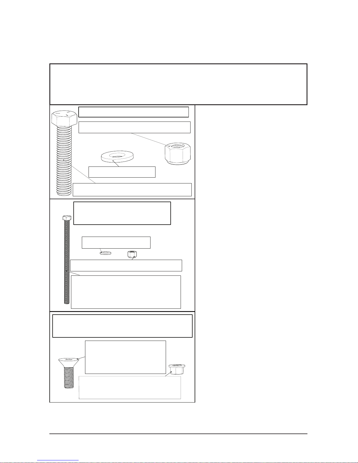
1/2"-13 Grade 5 Hex Bolt
at least 2 1/2" longer than
width of Glulam (2)
1/2" Washer (4)
1/2"-13 Nylon Lock Nut (2)
Glulam Required Parts
(NOT PROVIDED)
1.2 Rapid Mount Commercial
Bolt Kits
The I-Beam Bolt Kit is included with both I-Beam and Glulam
brackets. Additional parts must be purchased if mounting to
a Glulam (with the glulam bracket) or Unistrut.
For mounting to steel
trusses over 3 inches in
width, use the I-Beam
mounting method. For
widths under 3 inches,
use Unistrut span
mounting.
If you wish to mount to
a different surface than
these listed here, contact
a structural engineer.
1/2"-13 x 2 1/2" Hex Bolt (4)
1/2"-13 Nylon Lock Nut (4)
1/2" Washer (8)
I-Beam Bolt Kit (Optional)
1/4"-28 x 3/4"
Countersunk Socket
Head Cap Screw (4)
1/4"-28 Flanged Distorted
Thread Locknut (4)
Rapid Mount Commercial Mounting
Plate Bolt Kit (Optional)
Direct Glulam mounting
starts on page 18
Glulam Bracket mounting
starts on page 21
I-Beam mounting
starts on page 25
Unistrut mounting
starts on page 29
© 2018 EnergyLogic, LLC Toll Free: 800 311 8828 Fax: 615 471 5202 www.energylogic.com 18
Rev. Date 062718
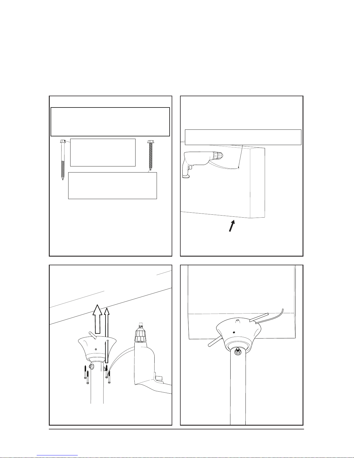
#10 2-1/2"
Lag Screw (4)
#10 1-3/4"
Concrete Screw (4)
Rapid Mount Commerical
Mounting Screws
1/8" safety cable clearance1/8" safety cable clearance
Glulam / Wood Beam
1.2.1 Rapid Mount Commercial
Glulam (Direct Mounting)
While concrete screws
are provided, contacting a
structual engineer is required
for mounting to Concrete.
Position the mount so that the
screws are as far away from the
edge of the beam as possible
Glulams and wood beams must be at least 6” wide to use this mounting
method. For narrower beams, use Glulam Brackets (sold separately) or
span across two or more beams using the Unistrut mounting method.
1/4”
Drill a pilot hole before
installing screws
© 2018 EnergyLogic, LLC Toll Free: 800 311 8828 Fax: 615 471 5202 www.energylogic.com 19
Rev. Date 062718
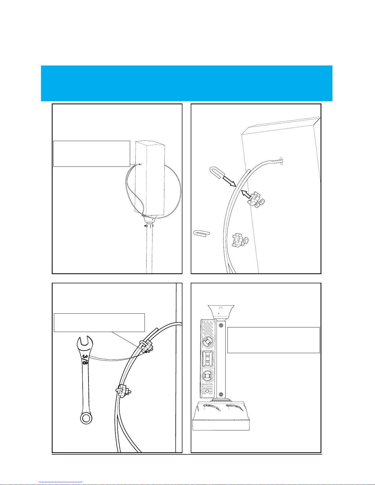
Run safety cable
though hole
Run safety cable
through hole
Tighten both nuts
Level Mount
1.2.1 Rapid Mount Commercial
Glulam (Direct Mounting)
WARNING: Do not put too much tension on the safety cable. There
needs to be a small amount of slack present in the safety cable for
proper functioning. Avoid sharp edges.
© 2018 EnergyLogic, LLC Toll Free: 800 311 8828 Fax: 615 471 5202 www.energylogic.com 2 0
Rev. Date 062718
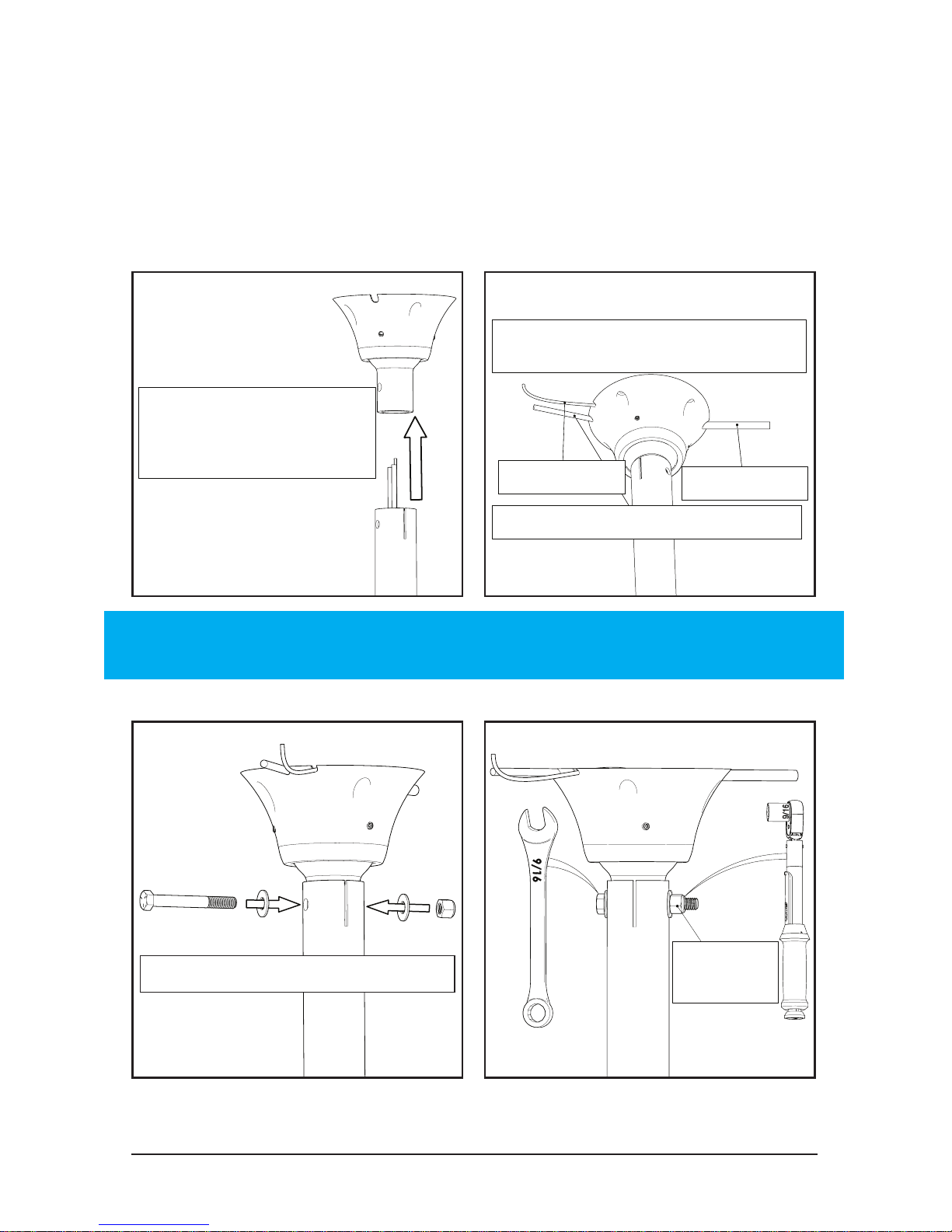
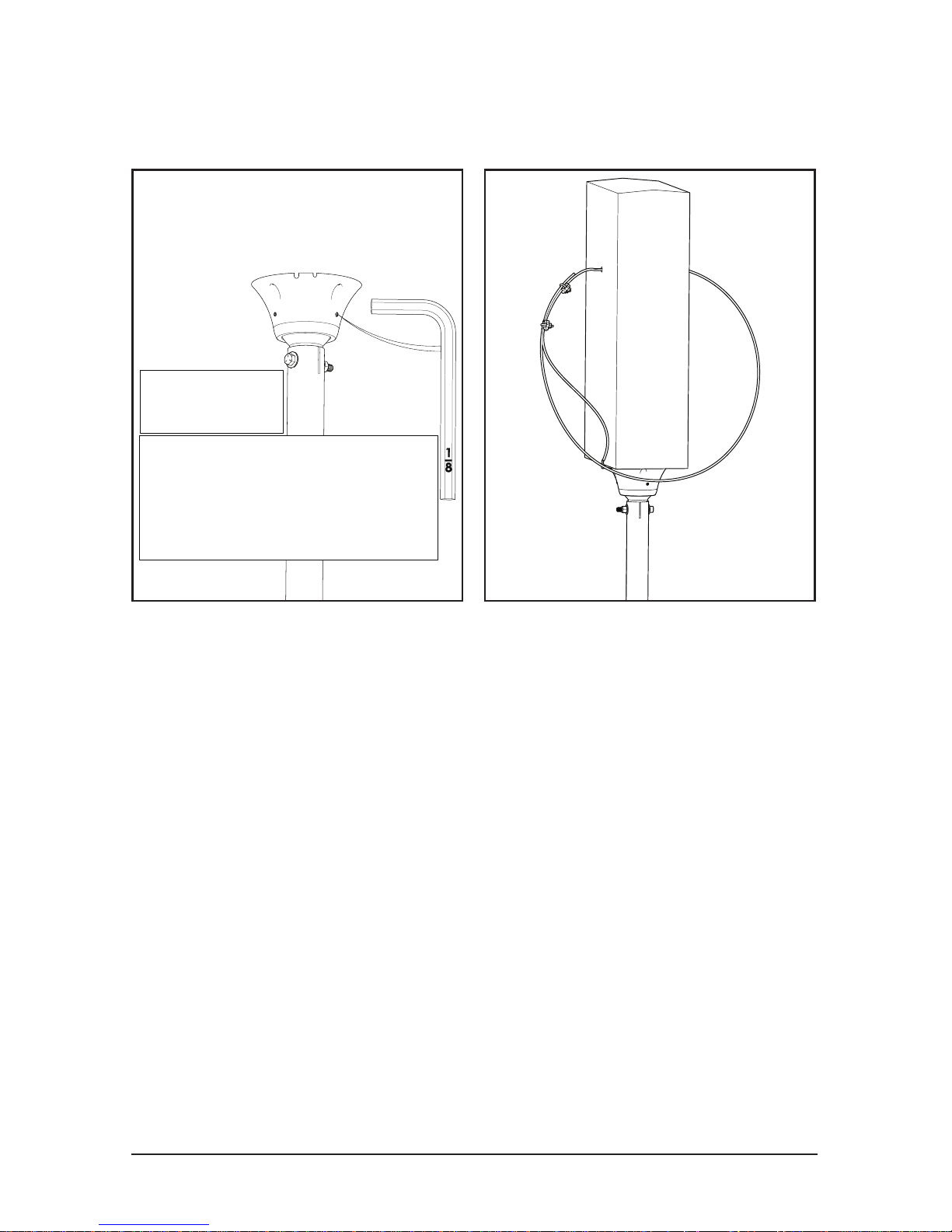
Tighten both
set screws
After tightening, move the
extension tube back and
forth, then tighten the set
screws again
1.2.1 Rapid Mount Commercial
Glulam (Direct Mounting)
1/8”
Complete safety cable installation and turn to page 50
© 2018 EnergyLogic, LLC Toll Free: 800 311 8828 Fax: 615 471 5202 www.energylogic.com 21
Rev. Date 062718
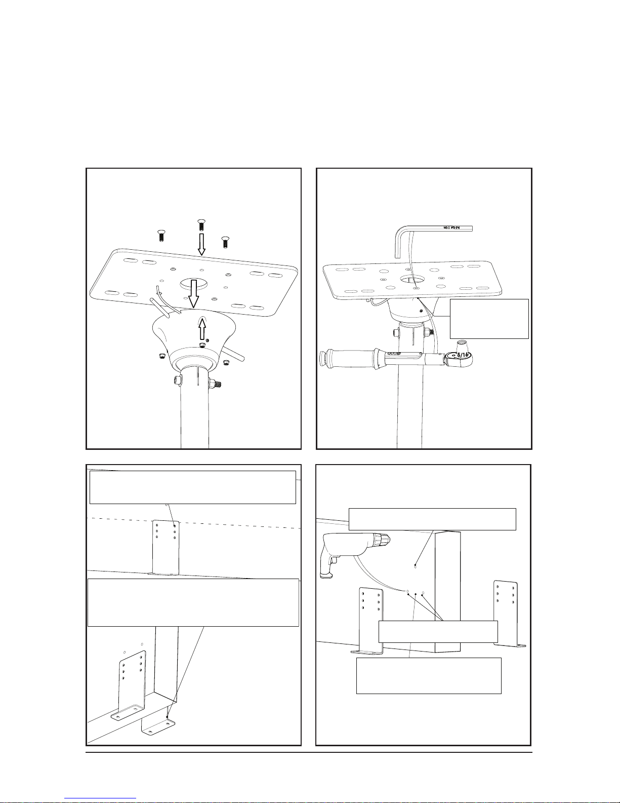
10 ft-lbs
10 ft-lbs
[14 N-m]
5/16”
5/32”
1/8" safety cable clearance
Holes can be oversized
for leveling the mount
1/2" bolt clearance
Use the two holes closest to
the center line of the glulam.
The bracket can be below the bottom
of the glulam if necessary but
is not recommended if it is avoidable.
1.2.2 Rapid Mount Commercial
Glulam (with Glulam Brackets)
This method is recommended for Glulams or wood beams between
4-1/8” or wider. For narrower beams, span across two or more beams
using the Unistrut mounting method.
 Loading...