


Installation &
Operation Manual
EL-200B, EL-375B, and EL-500B
115V/60Hz
Designed to save. Built to last. ™
5901 Crossings Boulevard
Nashville, TN 37013 www.energylogic.com (615) 471-5290
ASME Certified
Item # 98030034 Issue date: 26 March 2014
Caution!
Before you begin installation and operation of your boiler, read this manual completely, and save it for future reference!
IMPROPER INSTALLATION, OPERATION, OR MAINTENANCE OF THE BOILER SYSTEM CAN CREATE HAZARDOUS CONDITIONS AND WILL VOID THE WARRANTY AND U.L. LISTING
This boiler is UL listed for commercial and industrial use only. Refer to Section 1 for safety information and precautions.
Installation of the unit shall be made in accordance with all state and local codes which may differ from information provided in this manual. Installations in Canada shall be in accordance with the regulations of authorities having jurisdiction and installation practice shall be made according to CSA standard B139, Installation Code for Oil Burning Equipment.
Product improvements are occurring regularly, so the products may vary slightly from what is shown in this manual.
If you have any questions or concerns during the installation or operation of the boiler, contact your local service representative or EnergyLogic.
Thank you for purchasing an EnergyLogic boiler. Record the Unit I.D. Number below for future reference. Please register your unit to activate your warranty by visiting EnergyLogic’s website at www.energylogic.com/register . If you have any issues registering, please contact us at 615-471-5200.
I.D. Number:
(Located on the vessel skins, near the spec. label.)
Installed By:
(Service Company, Address,
Contact Name, Phone Number)
Date of Installation:
i
Call 1-615-471-5290 for Technical Support

Table of Contents
Before you begin................................................................................................................................... |
i |
|||
Table of Contents................................................................................................................................... |
ii |
|||
1. |
Safety, Codes and Regulations ......................................................................................................... |
1 |
||
|
1.1 |
Conventions Used in this Manual................................................................................................. |
1 |
|
|
1.2 |
General Warnings........................................................................................................................ |
2 |
|
|
1.3 |
Safety Hazards ............................................................................................................................ |
2 |
|
|
1.4 |
Codes and Regulations ............................................................................................................... |
4 |
|
|
1.5 |
Fuels and Fuel Management ....................................................................................................... |
5 |
|
|
1.5.1 |
Fuels ..................................................................................................................................... |
5 |
|
|
1.6 |
Clearances to Combustible Surfaces........................................................................................... |
6 |
|
2. |
Installation Considerations ................................................................................................................ |
7 |
||
|
2.1 |
Technical Guidelines ................................................................................................................... |
7 |
|
|
2.2 |
Tools Required ............................................................................................................................ |
8 |
|
|
2.3 |
Boiler Placement Guide ............................................................................................................... |
8 |
|
3. |
Assembly and Installation –Vessel, Tank, Pump and Suction Fuel Line .......................................... |
10 |
||
|
3.1 |
Unpacking and Inspection ......................................................................................................... |
10 |
|
|
3.2 |
Warranty Registration ................................................................................................................ |
10 |
|
|
3.3 |
Boiler Vessel Installation............................................................................................................ |
12 |
|
|
3.3.1 |
Vessel Installation ............................................................................................................... |
12 |
|
|
3.4 |
Preparing the EnergyLogic Used-Oil Tank................................................................................. |
13 |
|
|
3.4.1 |
Tank Vent Installation – EnergyLogic Tanks........................................................................ |
13 |
|
|
3.4.2 |
Drain Valve Installation – EnergyLogic Tanks ..................................................................... |
13 |
|
|
3.4.3 |
Low Fuel Cutoff Switch – EnergyLogic Tanks ..................................................................... |
13 |
|
|
3.5 |
Fuel Metering Pump and Filter Installation – EnergyLogic Tank (continue to section 3.6 if you |
|
|
|
don’t have EL tank)........................................................................................................................... |
14 |
||
|
3.5.1 |
Fire Stop Valve and Filter Head Installation – EL Tank........................................................ |
14 |
|
|
3.5.2 |
Metering Pump Installation – EL Tank................................................................................. |
14 |
|
|
3.5.3 Gauge and Pump Tubing Installation – EL Tank ................................................................. |
15 |
||
|
3.6 |
Metering Pump Installation – Non-EL Tank (skip if you have EL tank) ........................................ |
16 |
|
4. |
Installation of Boiler Components.................................................................................................... |
17 |
||
|
4.1 |
Vessel Panel and Insulation Assembly ...................................................................................... |
17 |
|
|
|
|
|
ii |
Call 1-615-471-5290 for Technical Support |
|
|||

|
4.2 |
Boiler Wire Harness and Controls Installation ............................................................................ |
18 |
|
|
4.2.1 |
Low Water Cutoff Probe and Control Installation. ................................................................ |
18 |
|
|
4.2.2 |
Triple Aquastat Temperature Controller Installation............................................................. |
19 |
|
|
4.2.3 |
High-Limit Temperature Controller Installation. ................................................................... |
20 |
|
|
4.2.4 |
Vessel Wire Box installation. ............................................................................................... |
21 |
|
|
4.3 |
Pressure Relief Valve and Combination Gauge Installation ....................................................... |
22 |
|
|
4.4 |
Domestic Coil (optional accessory)............................................................................................ |
22 |
|
|
4.5 |
Preheater Assembly .................................................................................................................. |
23 |
|
|
4.6 |
Burner/Vessel Assembly............................................................................................................ |
24 |
|
|
4.7 |
Pump Discharge (Outlet) Tubing Installation.............................................................................. |
27 |
|
|
4.7.1 Pump Discharge Tubing Installation ..................................................................................... |
27 |
||
|
4.7.2 |
Pump Discharge (Outlet) Tubing Installation – Guidelines................................................... |
28 |
|
|
4.8 |
Hydronics Connection and Boiler Mixing Valve Installation ........................................................ |
28 |
|
|
4.8.1 |
Hydronics Installation – Key Points ..................................................................................... |
28 |
|
|
4.8.2 |
Hydronics Set Up ................................................................................................................ |
29 |
|
|
4.8.3 |
Boiler Mixing Valve Set Up.................................................................................................. |
30 |
|
|
4.9 |
Filling the System ...................................................................................................................... |
30 |
|
5. |
Exhaust Flue System Installation .................................................................................................... |
31 |
||
|
5.1 |
Barometric Damper Tee Installation........................................................................................... |
31 |
|
|
5.2 |
Flue Piping Installation............................................................................................................... |
31 |
|
|
5.3 |
Draft Gauge Installation (included with some packages)............................................................ |
34 |
|
6. |
Electrical System Installation........................................................................................................... |
35 |
||
|
6.1 |
Wall Thermostat and Low Fuel Cut-Off Switch Installation (Optional Accessories) .................... |
35 |
|
|
6.1.1 |
Wall Thermostat Installation ................................................................................................ |
35 |
|
|
6.1.2 |
Low Fuel Cut-Off Installation ............................................................................................... |
35 |
|
|
6.2 |
Fuel Pump Power Connection ................................................................................................... |
36 |
|
|
6.3 |
Main Electrical Connection ........................................................................................................ |
37 |
|
7. |
Startup and Operation ..................................................................................................................... |
38 |
||
|
7.1 |
Do’s and Don’ts/Tech Tips......................................................................................................... |
38 |
|
|
7.2 |
Burner Primary Control Operation.............................................................................................. |
38 |
|
|
7.3 |
Safety Systems and Warnings................................................................................................... |
40 |
|
|
7.4 |
Boiler Startup............................................................................................................................. |
40 |
|
|
7.4.1 |
Fuel System Priming ........................................................................................................... |
41 |
|
|
7.4.2 |
Starting the Boiler................................................................................................................ |
42 |
|
|
7.4.3 Burner System Checkout .................................................................................................... |
43 |
||
iii
Call 1-615-471-5290 for Technical Support

7.5 |
Everyday Operation of Your EnergyLogic Used Oil Boiler ...................................................... |
46 |
||
8. Maintenance ................................................................................................................................... |
47 |
|||
8.1 |
Service Contracts ...................................................................................................................... |
48 |
||
8.2 |
Safety Warnings – Lockout/Tagout ............................................................................................ |
48 |
||
8.3 |
Monitoring System Performance over Time ............................................................................... |
48 |
||
8.4 |
Maintenance Schedule and Parts .............................................................................................. |
48 |
||
8.5 |
Maintenance Procedures........................................................................................................... |
50 |
||
8.5.1 |
Heat Exchanger Cleaning / Door and Access Insulation Checks......................................... |
50 |
||
8.5.2 |
Low Water Cut Off Testing and Probe Inspection................................................................ |
52 |
||
8.5.3 |
Fuel Oil Filter Replacement ................................................................................................. |
54 |
||
8.5.4 |
Preheater Cleaning ............................................................................................................. |
55 |
||
8.5.5 |
Nozzle Line Assembly Cleaning .......................................................................................... |
57 |
||
8.5.6 |
Retention Head and Electrode Settings............................................................................... |
60 |
||
8.5.7 |
Solenoid Valve Cleaning ..................................................................................................... |
62 |
||
8.5.8 Air Compressor Maintenance .............................................................................................. |
64 |
|||
8.6 |
Seasonal Shut Down & Start Up................................................................................................ |
66 |
||
9. Troubleshooting .............................................................................................................................. |
67 |
|||
9.1 |
Troubleshooting Condition Table ............................................................................................... |
68 |
||
9.2 |
Troubleshooting Trees............................................................................................................... |
69 |
||
9.3 |
Testing Procedures ................................................................................................................... |
72 |
||
9.3.1 Wall Thermostat (if equipped) and Burner Thermostat Circuit Testing.................................. |
72 |
|||
9.3.2 Water Circulator Pump Testing ............................................................................................ |
73 |
|||
9.3.3 Cad Cell Testing................................................................................................................... |
74 |
|||
9.3.4 Metering Pump Assembly Testing ........................................................................................ |
75 |
|||
9.3.5 Preheater and Nozzle PTC Testing Procedure..................................................................... |
77 |
|||
9.3.6 Primary Control Testing........................................................................................................ |
79 |
|||
9.3.7 Solenoid Valve Testing......................................................................................................... |
80 |
|||
9.3.8 Top Suction Kit Testing ........................................................................................................ |
81 |
|||
9.3.9 Iron Core Transformer Testing ............................................................................................. |
82 |
|||
9.3.10 Boiler Control Testing / Wiring Troubleshooting.................................................................. |
84 |
|||
10. Appendices ................................................................................................................................... |
86 |
|||
10.1 |
Boiler Wiring and Oil Schematic............................................................................................... |
86 |
||
10.2 |
Boiler Specifications ................................................................................................................ |
89 |
||
10.3 |
Limited Warranty ..................................................................................................................... |
93 |
||
iv
Call 1-615-471-5290 for Technical Support
1. Safety, Codes and Regulations
Thank you for the purchase of an EnergyLogic used oil boiler. EnergyLogic boilers are thoroughly tested for safe, long-term operation. However, proper installation, fuel quality control, and regular maintenance are required to ensure safe, long-term operation. Please read and understand this manual completely before attempting to install, operate, or service the boiler. Post this instruction manual and maintain it in legible condition. If you have any questions, call your local service provider or the number below for EnergyLogic Technical Service.
1.1 Conventions Used in this Manual
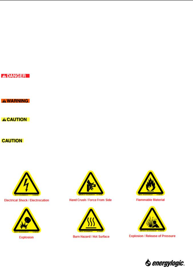
For your safety, this manual uses the following definitions and signal words to identify hazards:
Danger: Indicates an imminently hazardous situation which, if not avoided, will result in death or serious injury. This signal word is limited to the most extreme situations.
Warning: Indicates a potentially hazardous situation which, if not avoided, could result in death or serious injury.
Caution: Indicates a potentially hazardous situation which, if not avoided, may result in minor or moderate injury. It may also be used to alert against unsafe practices.
Caution (without alert symbol): Indicates an unsafe practice which, if not avoided, may result in product or property damage. Also used for general alerts.
Product safety labels and their meaning (labels not used on all products):
1
Call 1-615-471-5290 for Technical Support
1.2 General Warnings
 The EnergyLogic burner is to be used only in the EnergyLogic boiler provided. Do not attempt to use the burner for other purposes.
 Do not tamper with the unit or controls – call your service technician.
 Do not attempt to use unit with broken or damaged components.
 Do not allow unqualified personnel to install or service the boiler, electrical system, or flue system. Contact EnergyLogic for help with finding a qualified installation and service company. Failure to install and maintain your boiler properly will void your warranty and the UL listings.
 Do not attempt to start the burner when excess oil has accumulated, when the boiler is full of vapor, or when the combustion chamber is very hot.
 Do not start the burner unless all cleanout panels are secure in place.
 KEEP THE FUEL VALVE NEAREST THE SUPPLY TANK SHUT OFF WHEN THE BURNER IS SHUT OFF FOR EXTENDED PERIODS.
 Turn off power to the burner when the burner is off for extended periods.
 The boiler is designed to be installed in a manner that restricts its access.
 USED OILS CONTAIN HEAVY METALLIC COMPOUNDS AND FOREIGN MATERIALS. WHEN BURNED, THESE COMPOUNDS ARE EMITTED FROM OR DEPOSITED WITHIN THIS HEATING APPLIANCE AND THEREFORE CARE SHOULD BE TAKEN WHEN USING, CLEANING AND MAINTAINING THIS EQUIPMENT.
 EnergyLogic recommends that the building, domestic hot water system or process have a secondary heat source during times the boiler is down for maintenance or service. Used oil boilers require maintenance. Also, used oil may sometimes be unavailable or burn poorly due to contaminants (such as water) in the oil.
1.3 Safety Hazards
There are potential hazards associated with operation of this or any other boiler. In addition to the codes and regulations listed in the following section, general safety rules and precautions should be followed at all times to prevent accidents that could lead to personal injury, death or property damage. Only those qualified should perform the tasks. Specific safety hazards include:
 Electricity: The EnergyLogic boiler operates on 115V/60Hz electrical power. Turn power off at the circuit breaker and lock it out prior to performing any work on the boiler system or any of the components. Make sure covers are in place during normal use. Use only copper conductors.
 Liquid Fuels: Used oils must be handled properly to prevent spills. Uncontained oil leaks may contaminate the local water supply. Ensure that all national and local codes are
2
Call 1-615-471-5290 for Technical Support
followed in regards to the requirements for spill containment and SPCC paperwork. Oil leaks pose slip/fall hazards, and pose a risk for fires. DO NOT USE GASOLINE OR ANY OIL CONTAINING GASOLINE. Do not add any cleaning fluids or oil additives to the used oil burned in this appliance. The use of unauthorized fuels will void the warranty and U.L. listing. See section 1.5.1 for a list of allowable fuels. The end user of the boiler is responsible for ensuring that all correct precautions are taken in managing their used oil.
 Combustion Exhaust Gases: The exhaust products from the combustion are dangerous to breathe. The boiler must be attached to a flue which properly vents the exhaust out of the building to the atmosphere at all times, to assure safe and proper operation of the burner. If proper draft cannot be established, changes to the building construction or a draft inducer will be required in order to provide adequate make-up air.
 Safe Maintenance: Used oil contains mineral additives and deposits called “ash” that will not burn. Ash collects in the boiler and flue with regular use over time. Ash must be cleaned out of the combustion chamber/heat exchanger and flue pipe on a scheduled basis. Follow the minimum maintenance instructed in section 8. Wear proper protective clothing; including gloves, safety glasses, and a dust mask or respirator whenever any cleaning is performed, including the cleaning of the heat exchanger, flue piping and exhaust stack.
 Vapor/Dust Ignition: Do not store or use gasoline or other flammable liquids or vapors near this boiler, as they may be ignited by the burner. Do not operate the boiler in dusty or otherwise dangerous environments.
 Flammable liquids: Do not create a fire or explosion hazard by using or placing flammable liquids such as gasoline or solvents near the boiler. A flammable liquid is any liquid that has a closed-cup flash point below 100°F (37.8°C), as determined by the test procedures and apparatus set forth in 1.7.4 of NFPA 30.
 Minimum Clearance – Safe clearance to combustibles (Section 1.6) shall be adhered to.
 Height, Weight, Guarding and General Safe Practices: The boilers are installed with flue systems at heights which pose a risk for injuries due to a fall. Many of the components are heavy, and pose the risk of injury with improper lifting and handling. Always follow safe practices and use proper equipment. Never climb on the equipment. Do not take risks when installing or servicing the equipment. All cover plates, enclosures, and guards must be maintained in place at all times, except during maintenance and servicing. Failure to observe general safety rules and to follow safety rules specific to the tools and equipment used or being worked on may result in product/property damage, personal injury or death.
3
Call 1-615-471-5290 for Technical Support

1.4 Codes and Regulations
The installation, operation, and maintenance of the boiler system in the United States must be performed by qualified personnel in accordance with this manual and all national, state, and local codes / regulations, as well as the following standards of the National Fire Protection Association (NFPA) and the American Society of Mechanical Engineers (ASME):
ASME |
Boiler Code Section IV |
ASME CSD-1 |
Controls and Safety Devices for Automatically Fired Boilers |
NFPA 31 |
Standard for the Installation of Oil Burning Equipment |
NFPA 30 |
Flammable and Combustible Liquids Code |
NFPA 30A |
Code for Motor Fuel Dispensing Facilities and Repair Garages |
NFPA 70 |
National Electric Code |
NFPA 88A |
Standard for Parking Structures |
NFPA 88B |
Standard for Repair Garages |
NFPA 211 |
Standard for Chimneys, Fireplaces, Vents and Solid Fuel Burning |
|
Appliances |
These standards are available from the NFPA at www.nfpa.org, and from the ASME at http://www.asme.org/.
Similarly, the installation, operation, and maintenance of the boiler system in Canada must be performed by qualified personnel in accordance with this manual and in accordance with all the regulation authorities having jurisdiction, as well as CSA Standard B 139, Installation Code for Oil Burning Equipment, B140.0 – General Requirements for Oil Burning Equipment, B140.7.2
– Oil Fired Steam and Hot Water Boilers for Commercial and Industrial Use, B214 – Installation Code for Hydronic Heating Systems. Electrical installation in Canada shall be in accordance with C22.1 - Canadian Electrical Code, Part I. CSA standards are available at www.csa.ca.
A qualified installer is an individual or agency who is responsible for the installation and adjustment of the equipment and who is properly licensed and experienced to install oil burning equipment in accordance with all codes and ordinances.
In the United States, make sure you comply with all EPA regulations concerning the gathering and storing of used oil, and operation of the boiler. Specifically, CFR Title 40 Part 279 covers managing used oil. As well, make sure you comply with local codes and regulations.
In Canada, only used oil generated on the premises of the owner may be used in this equipment unless written authorization is obtained from the regulatory authority. Comply with Canadian regulations regarding the management and storing of used oil, as well as any local codes and authorities having jurisdiction
4
Call 1-615-471-5290 for Technical Support
1.5 Fuels and Fuel Management
The boiler system is composed of several components and subsystems that work together for efficient and safe operation. In order for the system to function as designed, good fuel management practice must be followed.
1.5.1 Fuels
EnergyLogic boilers are listed by Underwriters’ Laboratories (U.L.) for the U.S. and Canada, operating on the following fuels:
Used Crankcase Oil.
Used Automatic Transmission Fluid.
ASTM D396 No. 2 Fuel Oil.
DO NOT USE GASOLINE OR ANY OIL CONTAINING GASOLINE.
Fuel mixtures must have a minimum flash point of 140°F (60°C) and the maximum flash point of approximately 400°F (204°C). Mixtures shall not contain hazardous waste.
 Never mix inappropriate or hazardous material with the used oil. Examples of substances that should never be added include but are not limited to:
Gasoline |
Any Chlorinated Material |
Kerosene |
Parts Washer Solvents |
Hazardous Waste |
Oil Additives |
Anti-freeze |
Animal Fats |
Carburetor Cleaner |
Brake Fluid |
Paint Thinner |
|
 The addition of inappropriate substances to the fuel is not approved and can lead to poor equipment performance, premature product failure, and/or explosive/hazardous conditions. Burning of fuels that contain unapproved substances will void the product warranty and the UL listing. If you have any question about what is contained in your used oil, it is your responsibility to have the oil analyzed prior to burning.
Contact EnergyLogic Technical Services if you have questions about a particular fuel type, or if you need fuel analysis. For a nominal fee, EnergyLogic Technical Services will provide a professional fuel analysis. You will be provided with instructions in order to collect an oil sample to be sent out for analysis. Specify the type of analysis that is needed.
5
Call 1-615-471-5290 for Technical Support
1.6 Clearances to Combustible Surfaces
 It is of the utmost importance that the installation conform to the minimum clearances to combustible surfaces (Material made of or surfaced with wood, compressed paper, plant fibers, plastics, or other material that can ignite and burn, whether flame proofed or not, or whether plastered or unplastered). Consult applicable codes and regulations for precedence. Non-compliance to minimum clearances may result in fire, explosion, personal injury or death. The U.L. Listing specifies: “For all boilers rated for 50 psi or less and for all water boilers, installation clearances are Form III.” & “The boilers are intended for installation on noncombustible flooring.” The clearances for each model follow:
|
|
Model |
|
Minimum clearance from: |
EL-200B |
EL-375B |
EL-500B |
Top & pipe connections |
18" |
18" |
18" |
Front - (burner location) |
48" |
48" |
48" |
Sides |
18" |
18" |
18" |
Rear |
18" |
18" |
18" |
Flue Pipe |
18" |
18" |
18" |
Bottom |
Must be on non-combustible flooring. |
||
18” Flue Pipe
48” Front
18” Sides, Top
and Rear
Non-combustible Flooring
Minimum Clearances
6
Call 1-615-471-5290 for Technical Support

2. Installation Considerations
EnergyLogic boilers are designed to operate reliably over a wide range of conditions. However, it is important to read this section before installation to prevent unnecessary work or problems.
2.1Technical Guidelines
1.Most components of your boiler are factory-tested to ensure proper operation. Do not tamper with factory settings or fittings. The settings on the triple aquastat may be adjusted.
2.Pre-assembled fittings are sealed with thread-locker sealant and do not require additional tightening.
3.Always supply power through a dedicated, hard-wired (copper only), 115VAC/60Hz circuit with a 25 Amp maximum breaker. Check local codes.
4.Do not use the provided thread-locker sealant on flare fittings. Use the provided sealant on all NPT fuel line connections only.
5.Do not use Teflon tape on any fuel connections. Loose strands may block small orifices, affecting unit operation or may damage components.
6.Route all fuel lines inside building to prevent exposure to cold weather. If this is not practical, call EnergyLogic for application support.
7.Locate boiler and tank in a dry area above 50°F (10°C) at all times.
8.If not installing the pump to an EnergyLogic Tank, mount it according to guidelines in the EnergyLogic Top Suction Kit packaging instructions.
9.Do not kink copper tubing. Route tubing as straight and vertical as possible to avoid air pockets.
10.Maximize vertical run of flue, and minimize horizontal run. Allow access for clean-out.
11.Do not allow your tank to run out of fuel. If the tank runs out of fuel, air and contamination will be introduced into the fuel delivery system. An optional EnergyLogic low-level cut off switch is recommended to prevent low fuel operation.
12.Never use compression fittings for fuel tubing connections, as they will leak and cause the burner to shut down.
13.Care should be taken not to over tighten or cross thread brass fittings.
14.Applying a thin film of anti-seize compound to burner gasket may reduce gasket sticking to vessel when servicing.
15.Another source of heat is recommended for periods when the boiler may be off-line for maintenance or for any other reason.
7
Call 1-615-471-5290 for Technical Support
2.2 Tools Required
Below is a recommended list of tools and equipment that may be used to aid in the installation of the EnergyLogic boiler. This is a minimum list for a simple system, excluding the hydronics and plumbing.
5/16” Combination Wrench |
Pipe Wrench Set |
3/8” Combination Wrench |
Flat Blade Screwdriver |
7/16” Combination Wrench (x2) |
1/4” Hex Wrench or Driver |
1/2” Combination Wrench |
Wire Cutter (to remove tie straps) |
5/8” Combination Wrench |
Lift Device |
11/16” Combination Wrench |
Safety Ladder or Lift |
3/4” Combination Wrench |
(Tools Required for Flue Kit Installation) |
2.3 Boiler Placement Guide
It is important to plan the boiler and tank placement, wiring, piping and flue prior to installation.
Electrical Wiring - Will the layout of your building allow safe routing and installation of electrical wiring to the boiler? Check your local building codes. The EnergyLogic boiler requires 115VAC/60Hz power, supplied through a dedicated, hard wired, circuit breaker - 25Amp maximum. Use copper conductors only.  Electricity is very dangerous. Wiring must be installed by a qualified electrician. In the U.S., consult the National Electric Code (NEC) and local building codes for additional requirements. In Canada, consult the Canadian Electrical Code, Part I.
Flue Pipe - Is ceiling/roof or wall location suitable for a flue pipe to pass through? Are any obstacles present at interior or exterior locations? Check your roof warranty about penetration of the flue pipe. Check your local building and fire codes.
Combustion and Make Up Air Requirements –  It is necessary to ensure that adequate air for safe combustion is provided for oil-burning appliances and equipment. Refer to NFPA 31, Chapter 5 for requirements based on the total input BTU rating of all appliances in the space. In Canada, reference CSA Standard B139/CGA B149.
Tanks - The oil tank is to be vented to the outside of the building. Oil temperature should be maintained at 50°F (10°) and above. Tank shall be at least 5 feet away from any source of heat and should not obstruct service meters, electrical panels, or shut off valves. Check building, environmental and fire codes for containment and other restrictions.
Minimum Clearance –  Safe clearances to combustibles (Section 1.6) shall be adhered to. A non-combustible flooring structure is required for the boiler.
8
Call 1-615-471-5290 for Technical Support

Distance from Flammable Liquids –  Do not create a fire or explosion hazard by using or placing flammable liquids such as gasoline or solvents near the boiler. A flammable liquid is any liquid that has a closed-cup flash point below 100°F (37.8°C), as determined by the test procedures and apparatus set forth in 1.7.4 of NFPA 30.
Access - Position the used oil storage tank to provide adequate access to filling ports, filter, drain valve and pump. Leave an unobstructed path for shop vehicles and equipment. Consider access needed for service (heat exchanger cleaning, flue cleaning, removal of breech panels, burner access, etc.). Installation of system piping should not hinder required access for service.
Vessel Placement in Motor Fuel Dispensing Facilities and Repair Garages – Heat producing appliances shall not be allowed unless installed with provisions outlined in NFPA 30A, section 7.6.
Structural requirements (Canada) – In Canada, the structure in which the used oil burning appliance is housed shall be no less than 4.6m (15ft) high at the point where the appliance is situated and have a minimum length and width of 6m (20ft) and a minimum floor area of 37m2 (400ft2). In addition, the installation including flue stack height requirements and distance from property line shall be in accordance with the authorities having jurisdiction concerning environmental quality as well as fuel, fire, and electrical safety and Table 7 in CSA B140.0-03 (clause 22.3.2).
Other Considerations for EnergyLogic Boilers:
They are constructed with ASME certified pressure vessels (30 psi maximum pressure).
The ASME  stamp is located on boiler plate on the vessel under a removable panel. They have Canadian Registration. The CRN number is located on the boiler plate. They are UL Listed in the US and Canada. The UL mark and specification label are on a boiler panel.
They are fire-tube boilers. This means that hot combustion gases flow through tubes, transferring heat to water that surrounds the tubes.
They are carbon steel boilers. With a ¼” steel shell, they are of a durable construction, and much lighter than cast iron models. Since they are carbon steel however, there are some restrictions on the return water temperature to prevent corrosion (minimum return temperature of 140°F).
They are wet-based boilers. This means that the combustion chamber and tubes are surrounded by water that keeps the steel cool and prevents chamber deterioration. They are non-condensing boilers. This means that the flue gases are not allowed to cool enough to create condensation. Due to sulfur in the oil, condensation would create sulfuric acid which would quickly corrode the boiler tubes and chamber.
9
Call 1-615-471-5290 for Technical Support

3. Assembly and Installation –Vessel, Tank, Pump and Suction Fuel Line
This section instructs installing the fuel delivery system (side suction or top suction) and mounting the vessel.
3.1 Unpacking and Inspection
After unpacking your new boiler, make sure you have received the proper parts and quantities shown in the checklist on the following page. For missing parts, contact EnergyLogic. If any parts were damaged during shipment, please contact your shipping carrier.
3.2 Warranty Registration
IMPORTANT: You must register your boiler with EnergyLogic for the warranty to become active and to receive technical service.
Please take a few minutes to fill out the Warranty Registration Card.
Note: Your Warranty Registration Card may be found in the accessory box where you located this manual. You may fax the completed card to us at (615) 251-0682, or mail it. You may also register online at www.energylogic.com.
10
Call 1-615-471-5290 for Technical Support

|
|
No. |
Item |
|
Qty. |
|
|
|
|
Boiler Vessel Assembly |
|
|
|
|
|
|
1a. Boiler Vessel (with trim |
|
|
|
|
|
|
kit) |
|
|
|
|
|
|
1b. Boiler panels and |
|
|
|
|
Up |
|
Insulation panels. |
|
|
|
|
1 |
1c. Controls/ Wire Harness. |
|
1 set |
||
|
Pick |
|
||||
|
2 |
Preheater Assembly |
1 |
|||
|
Fuel |
3 |
Burner Assembly |
1 |
||
|
|
|||||
|
Suction |
4 |
Air Compressor Filter |
1 |
||
|
6 |
Alligator Clips |
2 |
|||
|
|
5 |
Burner Gasket |
1 |
||
|
Side |
|
|
|
|
|
|
7 |
Filter Head and Fuel Filter |
1 |
|||
|
|
|||||
kit) |
with |
8 |
Fuel Pump Assembly |
1 |
||
9 |
Vacuum Gauge |
1 |
||||
|
|
|||||
complete(minus flue |
BoilerAssembly |
10 |
Pressure Gauge |
1 |
||
|
(provided with bundles |
|
|
|||
|
|
|
Barometric Damper and Tee |
|
|
|
|
|
11 |
Assembly |
1 |
||
|
|
|
Draft Gauge (provided with |
|
|
|
|
|
12 |
bundles only) |
(1) |
||
Boiler |
|
|
Draft Gauge Probe |
|
|
|
|
13 |
Thread Sealant Tube (not |
(1) |
|||
|
|
only) |
||||
|
|
14 |
shown) |
1 |
||
|
|
|
|
|
|
|
|
Assy |
|
EnergyLogic Workbench |
|
|
|
|
15 |
Tank |
1 |
|||
|
Tank |
16 |
Drain Valve Assembly |
1 |
||
|
|
|||||
|
|
17 |
Swing-Arm Fuel Gauge |
4 |
||
|
Kit |
|
3/8" Copper Suction Line |
|
|
|
|
Suction |
|
|
|
||
|
18 |
with Flare Nuts |
1 |
|||
|
|
|||||
|
|
|
Low Fuel Cut Off Switch |
|
|
|
|
Side |
19 |
Assembly |
1 |
||
|
20 |
FireStop Valve Assembly |
1 |
|||
|
|
|||||
Checklist
Call 1-615-471-5290 for Technical Support
Included with EnergyLogic Boiler
20
17
Tank and Tank Options
11
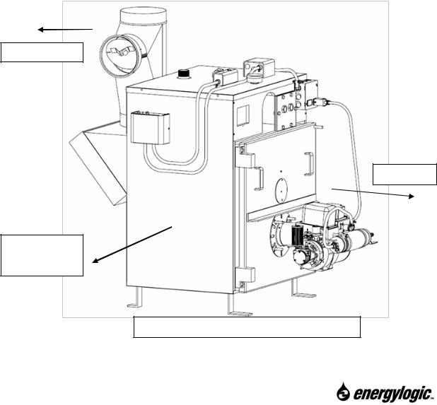
3.3 Boiler Vessel Installation
Note: This manual covers the installation of a single boiler and pump. If you are installing multiple boilers in the same building, contact your local dealer or EnergyLogic for additional installation options.
3.3.1 Vessel Installation
1.Uncrate and locate the vessel near the desired location.
2.Once the boiler vessel is in place, the vessel may be anchored.
3.Be sure to remove the trim package that contains the fittings and gauges. This is to be found in the rear breech / chimney connector.
4.Consider the following:
 Prior to placement, a licensed electrician shall install a dedicated 115vac/60Hz service junction box (switchable and lockable) in close proximity to the vessel location (preferably within 5 feet).
 A non-combustible platform or flooring structure is required.
 Pay special attention to Codes and Regulations in Section 1.4, and all local codes and regulations.
 Refer to section 2.3 for placement guidelines / restrictions for the boiler. The placement is critical for proper operation and efficient servicing.
EnergyLogic Boiler with EnergyLogic Tank
12
Call 1-615-471-5290 for Technical Support
3.4 Preparing the EnergyLogic Used-Oil Tank
If you are not installing an EnergyLogic Tank, first verify that your used oil storage system meets all applicable codes and requirements, then proceed to the instructions for installing the metering pump.
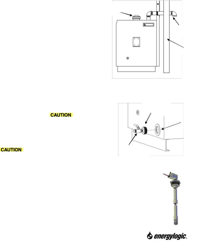
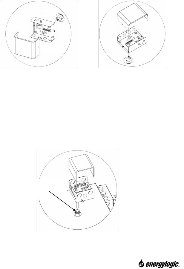
3.4.1 Tank Vent Installation – EnergyLogic Tanks
Once the tank is in place, install a tank vent (not included). This requires a minimum 1.25 inch NPT steel pipe routed through an exterior wall, terminated with a 90° elbow turned down (figure). A mushroom-style cap may be used to terminate the vent as an alternative to the down-turned elbow. Install appropriate Emergency Venting. EnergyLogic offers an emergency vent cap with capacity of 53,000 cu. ft./hr./1501 cu. m/hr. This optional accessory can be installed into a 4 inch NPT port (figure).
Emergency Vent Cap (sold separately).
Min. 1.25” NPT
Steel Pipe
Exterior Wall
3.4.2 Drain Valve Installation – EnergyLogic Tanks
Install the tank drain valve in a port along the bottom of the tank as shown in figure. Use the provided thread sealer on the threads during
installation. Note: Some tanks come with the drain |
Apply Thread |
|
|
Sealer |
|
||
2” NPT Port in |
|||
valve already installed. The drain valve is |
|||
|
|||
|
Tank Side |
||
necessary for draining water from the bottom of the |
|
||
|
|
||
|
|
||
tank. The drain valve is shown in closed position in |
|
|
|
figure. A plug should be installed in the drain valve to |
|
|
|
prevent accidental spills. |
|
|
|
After all components have been installed on |
Drain Valve |
|
|
the tank, make sure that all unused tank openings are |
Drain valve installation. |
||
|
|||
properly plugged.
3.4.3 Low Fuel Cutoff Switch – EnergyLogic Tanks
The low fuel cutoff switch is an optional accessory that will automatically shut off the burner if the tank is nearly out of fuel. This prevents the pump from losing prime. The float switch operates by interrupting the thermostat circuit when the fuel level is too low. Install the accessory according to the packaged instructions.
Call 1-615-471-5290 for Technical Support
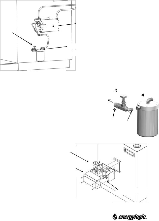
3.5 Fuel Metering Pump and Filter Installation – EnergyLogic Tank
(continue to section 3.6 if you don’t have EL tank).
On EnergyLogic Tanks, the fuel pump components are mounted on the side as shown. Follow the steps below to first install the firestop valve and filter head, and then install the pump.
|
|
Metering Pump |
|
|
Assembly |
Fire-Stop Valve |
|
|
|
|
|
|
|
|
|
|
|
Filter Head Assembly
 Spin On Fuel Filter
Fuel system – EL Tank
3.5.1 Fire Stop Valve and Filter Head Installation – EL Tank.
Decide which end of the tank is the best location for your pump. On EL 250 gallon and 500 gallon tanks, the pump may be mounted to either end. To install the firestop valve, first apply gasket sealer to the ¼” NPT fitting and screw the fire stop valve to the fuel filter head, fully tighten the NPT threads using a back up wrench. Then, apply sealer to the ½” NPT fitting and screw the entire filter head assembly with firestop valve into the ½” NPT port in the side of the tank (located about 10” up from the floor).
FireStop Valve |
Filter Head |
|
Assy. |
To Tank
Gasket sealer here, then tighten.
3.5.2 Metering Pump Installation – EL Tank
Mount the pump to the integrated bracket on the EnergyLogic tank using (4) 1/4-20 bolts.
Fuel Pump Assembly
Remove cover to install bolts. Replace cover after pump has been wired.
(4) 1/4 - 20 Bolts
Mount Pump to Tank
14
Call 1-615-471-5290 for Technical Support
3.5.3 Gauge and Pump Tubing Installation – EL Tank
Install the gauges and tubing as follows:
 The pump fittings are sealed and leak tested at the factory. Use a backup wrench when installing the gauges and flare fittings to ensure that you do not turn the pump fittings and create a leak.
1. Remove the plugs on the inlet and outlet tees (refer to figure). Note: The pumps are tested at the factory, so a small amount of oil may be present.
2.Using the gasket sealer provided, install the pressure gauge on the outlet tee, and the
combination vacuum/pressure gauge on the inlet tee.
Outlet Tee
Fuel Pump Assembly
3/8” Copper Tube
Filter Head Assembly
3.Locate the short 3/8” copper tube assembly. Carefully bend the tube (without kinking) into position as shown.
4.Thread (do not tighten) upper 3/8 inch flare nut onto the flare fitting on the fuel pump inlet. Do not apply gasket sealer to the flare fittings.
5.Thread lower fitting onto the filter head fitting.
6.Tighten both flare nuts. Use a backup wrench - do not over-tighten.
15
Call 1-615-471-5290 for Technical Support
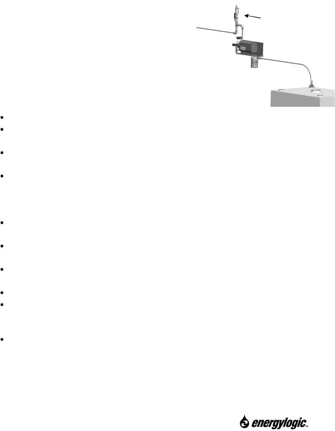
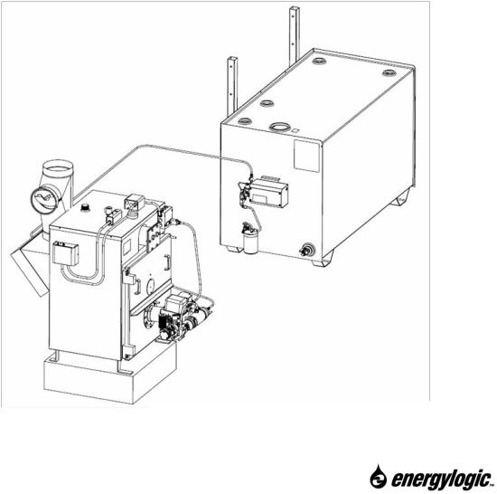
3.6 Metering Pump Installation – Non-EL Tank (skip if you have EL tank)
If you are metering fuel directly from a tank not supplied by EnergyLogic, the top suction method may be used. Verify regulations prior to installation. Contact your authorized EnergyLogic dealer to purchase an EnergyLogic Top Suction Kit if one was not included in your original purchase. The use of a genuine EnergyLogic Top Suction Kit (figure) will help to avoid common fuel delivery issues with this type of
installation.
Installation of the Top Suction System:
1.Install the vacuum and pressure gauges on the pump. Follow steps 1 & 2 in previous section.
2.If you purchased an EnergyLogic Top Suction Kit, follow the instructions included in the packaging. Refer to the following for general guidelines.
AirScape Accessory
(Optional)
EL Top Suction Kit Installed
Guidelines for Top Suction Method:
Purchase an EL Top Suction Kit (if your package did not include one).
Keep in mind that the main storage tank will need to have enough capacity to allow for separation of water from the used oil. Never meter oil directly from oil drums or totes.
EnergyLogic’s fuel pump is designed for interior use only (must be mounted inside a protective structure). The minimum recommended fuel temperature is 50oF.
The pump may be mounted to a nearby wall, within 6’ of the tank. The ideal placement of pump is with the inlet above the filter head assembly, which should be mounted above the tank fitting. Maximum vertical lift for the suction line should not exceed 6 feet (2m). This includes the portion of line inside of the tank.
The EL Filter Head Assembly is to be placed such that it filters the oil prior to pump. A shut off valve should be placed prior to the filter head in order to do a vacuum check.
The pump assembly and wiring connections must be at least 18 inches (46 cm) above the floor to meet National Fire Protection Association (NFPA) codes for repair garages.
The inlet to the suction line should be at least 8 inches (20 cm) off the bottom of the tank, to prevent water and sludge from entering the system.
Use minimum 3/8” OD x 1/32” wall thickness copper tubing. Never create loops.
Use 45 degree flares on the copper tubing. Loose fittings or cracked flares cause problems. Suction leaks cause air to get sucked into the fuel system. All suction leaks must be eliminated.
Used-oil contains water from condensation. A drain valve on the bottom of the tank should be used regularly to remove water and sludge that separates out of the oil and settles to the bottom of the tank. If your tank does not have a drain valve, you must have the tank pumped out completely (periodically) to remove the water and sludge.
16
Call 1-615-471-5290 for Technical Support
4. Installation of Boiler Components
With the vessel in place, you are ready to attach the vessel panels and insulation, the wire harness and controls, the optional domestic coil, and the burner/preheater assembly. Then, you will install the fuel tubing from the pump discharge to the preheater. Finally, your hydronics professional will connect the hydronic piping system to the boiler – and fill the system.
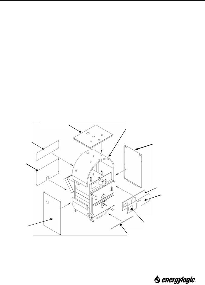
4.1 Vessel Panel and Insulation Assembly
Install the vessel panels and insulation as follows:
1.Open the box containing the insulation, panels, and hardware.
2.Wrap the insulation around the boiler vessel. Use the ribbon provided to secure the insulation around the vessel. Install the insulation for the front panel. Note: Make sure to cut out the insulation for ports and drains as needed. On front panel, make sure that the insulation is cut out to provide a view of the ASME boiler plate.
3.After the insulation is in place, install the panels as they are shown in the figure below, securing using the sheet metal screws provided. Install the side panels to the front and rear panels first. Then, install the remaining panels.
Rear Panel
Lower Panel
Side Panel
Wrap insulation around Top Panel the vessel and secure
using two ribbons.
Side Panel
Front Insulation
Front Panel
ASME Boiler Plate
Access Panel.
Brace
Assembling Insulation and Panels (EL-200B shown)
17
Call 1-615-471-5290 for Technical Support
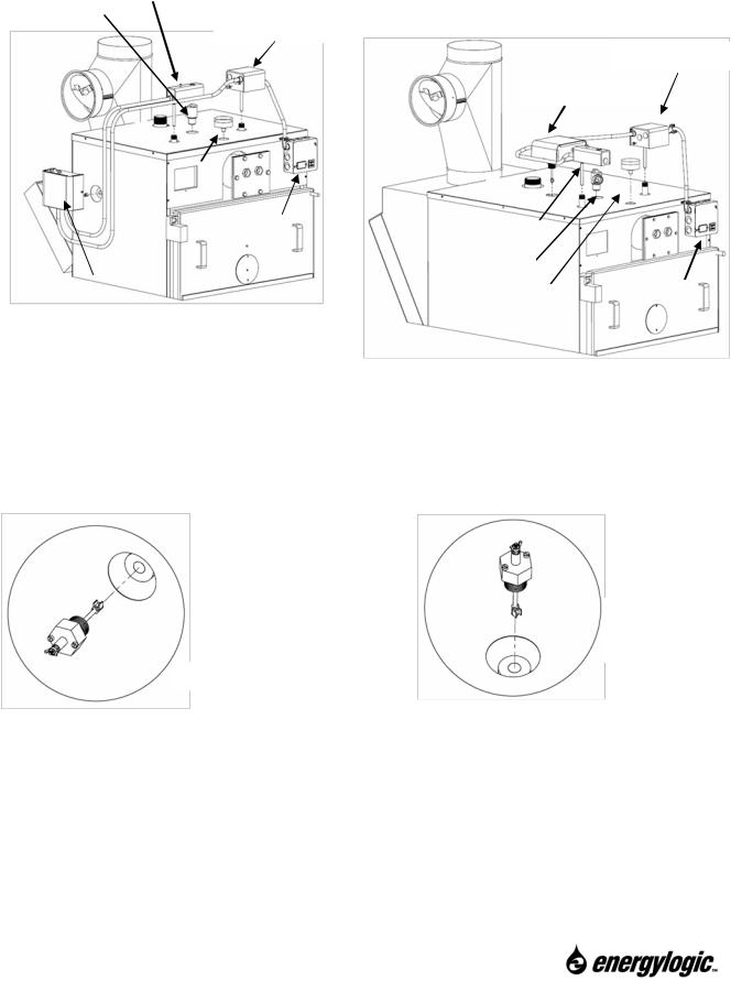
4.2 Boiler Wire Harness and Controls Installation
The boiler controls are pre-wired at the factory. You will install the pre-wired, steel conduit, wire harness to the vessel. Install the boiler wire harness and controls as follows:
High Temp Limit
Press. Relief
Triple Aquastat
Triple Aquastat
Low Water Cut Off
|
|
Gauge |
|
|
|
|
|
|
|
|
|
|
|
|
|
|
|
|
|
|
|
|
|
|
|
|
|
|
|
|
|
|
|
|
|
|
|
|
|
|
|
Vessel Wire Box |
|
|
|
|
|
|
|
|
|
|
|
|
|
|
High Temp Limit |
|
|
|
||||
|
|
|
|
|
|
|
|
|
|
|||
|
|
|
|
|
|
|
Press. Relief |
|
|
|
|
|
|
|
|
|
|
|
|
|
|
||||
|
|
|
|
|
|
|
|
|
|
|
|
|
|
|
|
|
|
|
|
|
|
|
|
|
Vessel Wire Box |
|
|
|
|
|
|
|
|
|
|
|
|
|
Low Water Cut Off |
|
|
|
|
|
|
|
|
|
|
||
|
|
|
|
|
|
Gauge |
|
|||||
|
|
|
|
|
|
|
|
|||||
|
|
|
|
|
|
|
|
|
|
|
|
|
|
|
|
|
|
|
|
|
|
|
|
|
|
Installing Controls on EL-200B
Installing Controls on EL-375B or EL-500B
4.2.1 Low Water Cutoff Probe and Control Installation.
1.Remove the probe from the Low Water Cutoff packaging. Locate the proper port as shown in figures above.
EL-375B
EL-500B
EL-200B
2.Prior to threading the probe into the port, use pipe dope on the first threads.  Do not use Teflon tape and do not cover all of the threads as metal-to-metal contact is necessary for proper electrical conduction and function of the probe.
3.Thread the probe into the port (  Do not use grease on this probe). Tighten. Align the probe so that the mounting screws are in a location that situates the installation of the control for best appearance (use the control as a guide). Loosen the probe mounting screws a couple of turns.
4.Remove the LWCO control from the packaging. Remove the cover from the control.
18
Call 1-615-471-5290 for Technical Support
5.Install the control over the probe, guiding the probe through the opening. With the mounting screws on the probe loosened, guide the screws into the slots, and tighten the screws securely to the base of the control.
EL-200B
EL-375B
EL-500B
6.Secure the “Probe” lead wire coming from the circuit board to the probe using the provided wing nut.
7.Install the cover to the control.
8.Note: An EL factory installed on-off switch is provided as part of this control. This switch may be used to turn power on and off to the boiler.
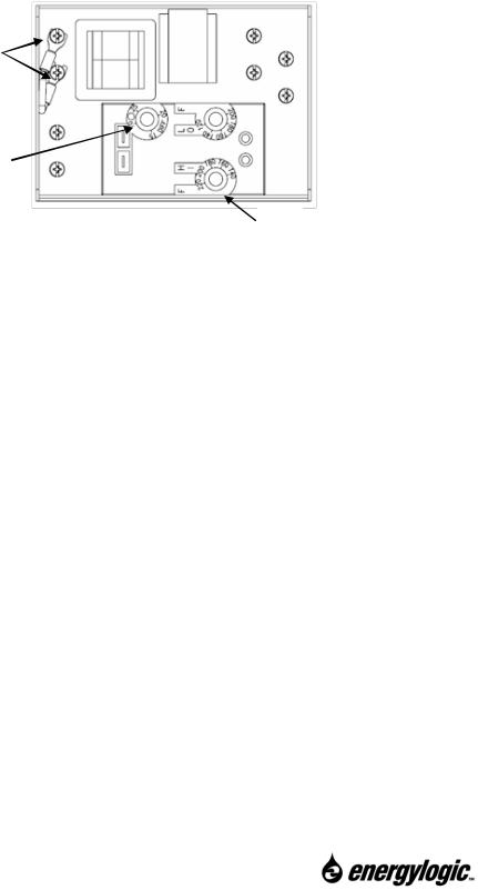
4.2.2 Triple Aquastat Temperature Controller Installation.
1.Remove the cover from the triple aquastat control.
2.Fill the triple aquastat thermal well (refer to figures) with thermal conductive grease (provided), as follows: Fold the plastic bag of compound lengthwise and twist it gently. Then snip off end of bag and work the open end of the bag all the way into the well. Slowly pull out the bag while squeezing it firmly to distribute compound evenly in the well. Wipe excess compound from the outer end of the well.
Fill Triple Aquastat Well with Thermal Conductive Grease before inserting probe.
3.Loosen but do not remove the clamp screw on the case. Insert the aquastat probe into the thermal well until it bottoms out.
19
Call 1-615-471-5290 for Technical Support
4.Fit the case onto the well so that the clamp on the case slides over the well. Securely tighten the clamp screw. Note: Align the controller prior to tightening securely.
5.Set the control settings to the desired temperatures. Set HI to the temperature that you want the water to reach during a call for heat. Set Lo to the temperature that you want the water to maintain in the vessel when there is not a call for heat. Set DIFF to an amount that you want the Lo setting temperature to cycle between. Note: The Hi limit must be set at least 20°F above the Lo limit setting.  Do not set the low limit below 140°F.
Remove jumper wire and install room thermostat here, if used.
 Lo
Lo
DIFF
HI
6.If a room thermostat (or other device) is to be used to call for heat, the factory-installed jumper wire will need to be removed from the triple aquastat and replaced with wiring (24VDC) from the thermostat (refer to figure above) If the jumper is not removed, the control will always sense a call for heat. If this is the case, the burner will always cycle between the high temperature limit and its fixed differential of 10°F, and the water circulation pump will be powered (if this control is used for the circulation pump).
7.If using the circulation pump control on the aquastat, wire the pump control across terminals C1 and C2 using a 115V coil relay to provide separate power to the pump. The amperage rating of the controller is limited to a total load of 8 amps, which is mostly consumed by the burner itself. The relay is necessary to make sure that the controller is not overloaded by the addition of the pump. Make sure to connect according to NEC code, with approved metal conduit. Note: Many installations use separate controls for the pump.  Regardless of the pump control method used, be aware of the requirement for a minimum of 140°F return water temperature. If this requirement is not met, the vessel warranty is void.
8.Install the cover to the control.
4.2.3 High-Limit Temperature Controller Installation.
1.Remove the cover from the high-limit temperature aquastat control.
2.Fill the high-limit temperature aquastat thermal well (locate well according to figures) with thermal conductive grease following the same procedure as in section 4.2.2.
20
Call 1-615-471-5290 for Technical Support
3. Insert the aquastat probe into the thermal well until it bottoms out.
Fill High-Limit Controller Well with Thermal Conductive Grease before inserting probe.
4.Install the control over the thermal well. Using the clamp provided on the bottom of the control, secure the control to the well. The screws to tighten the clamp are located inside of the control, on either side of the probe opening.
5.Make sure that the control is set to 230°F.  Do not increase the setting.
6.Install the cover to the control.
4.2.4 Vessel Wire Box installation.
1.Mount the wire box to the upper-right front panel (panel #4) using the sheet metal screws provided. Refer to figures for location of box.
2.Secure the conduit to the vessel panels using clamps and sheet metal screws provided.
EL-375B
EL-200B
(EL-500B is similar)
Boilers complete with Controls
21
Call 1-615-471-5290 for Technical Support
4.3Pressure Relief Valve and Combination Gauge Installation
1.Install the 30 psi pressure relief valve in the port shown in figures in the beginning of this section. Use pipe dope on the threads. Make sure to install metal piping from the relief valve; routed according to code to a safe place for discharge.
2.Install the combination temperature / pressure gauge in the port shown in the beginning of this section. Use pipe dope on the threads.
4.4Domestic Coil (optional accessory)
The boiler vessel has provision for an optional domestic coil (2 on EL-500B), which can be used for heating potable water in an open loop circuit.. Call if you have a need for this accessory.
Domestic Coil Location
Optional Accessory
22
Call 1-615-471-5290 for Technical Support
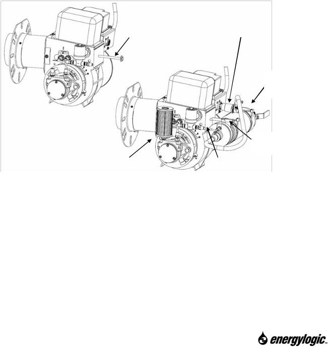
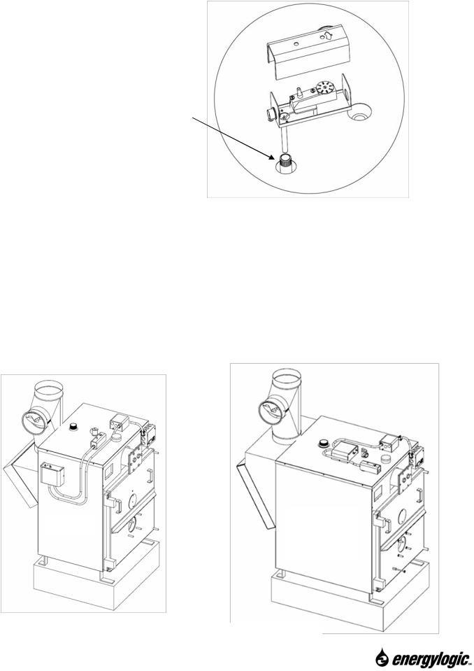
4.5 Preheater Assembly
Before installing the burner to the vessel, install the preheater, as follows:
Instructions for Model EL-200B:
1.Use the long bolt (provided with the preheater) to install the preheater. For the EL-200B, the preheater installs to the burner assembly as shown in figure below.
2.Remove the shipping caps on the preheater and burner. Note: The preheater and burner are tested during manufacturing, so a small amount of oil may be present when the caps are removed.
3.Cut the tie strap holding the 1/8” copper tubing, and thread (do not tighten) the fittings onto the burner solenoid valve and preheater, as shown in the figure.
4.Tighten the fuel tubing fittings and the long preheater bolt.
5.Screw the plug end of the conduit into the receptacle on the burner wire box.
6.Install the air filter by pressing it onto the compressor inlet.
|
|
Plug in |
Long Bolt (goes here) |
|
|
|
preheater. |
|
|
|
|
|
|
|
|
|
|
Install
Preheater
Install Long
Bolt
|
|
Install Fuel |
Install Air |
|
|
|
Tubing |
|
Filter |
|
|
|
|
|
|
|
|
|
|
|
EL-200B Preheater Assembly (to burner).
Instructions for Model EL-375B and EL-500B:
1.Use the long bolt (provided with the preheater) to install the preheater. For the EL-375B and the EL500B, the preheater installs directly to the vessel door. NOTE: The preheater installs on top of the bolt.
2.Align the preheater with a slight upward slope to allow air to escape. Do not tighten the bolt completely until you have installed the fuel tubing to the preheater in the next section.
23
Call 1-615-471-5290 for Technical Support
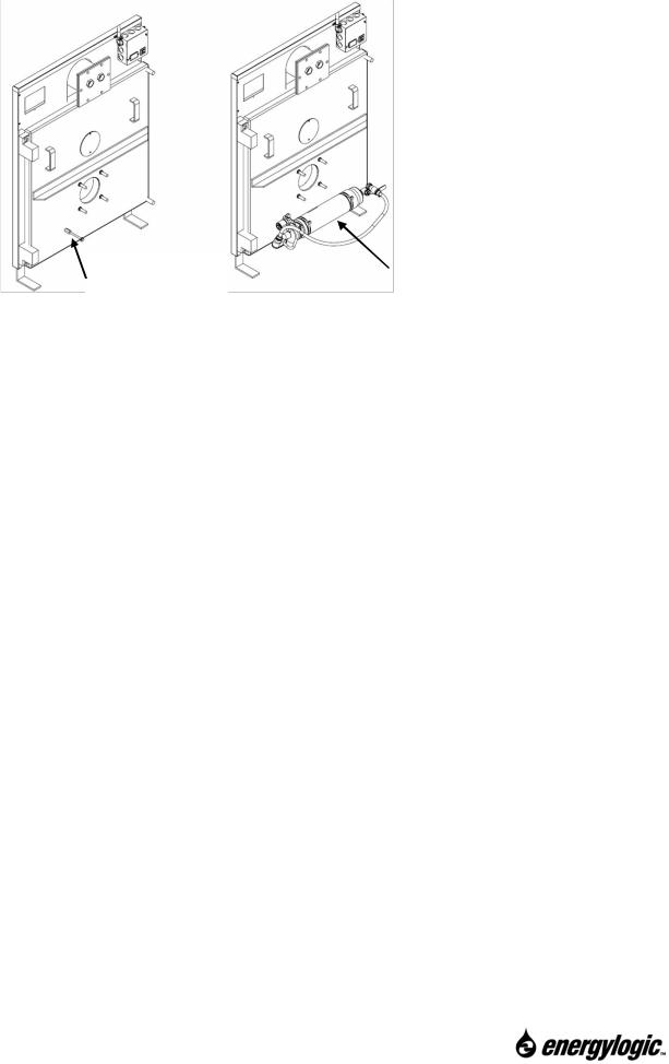
Install Long Bolt (goes Preheater here)
Installation of Preheater (to vessel door) for EL-375B and EL-500B
NOTE: The Preheater Mounts on Top of the Bolt.
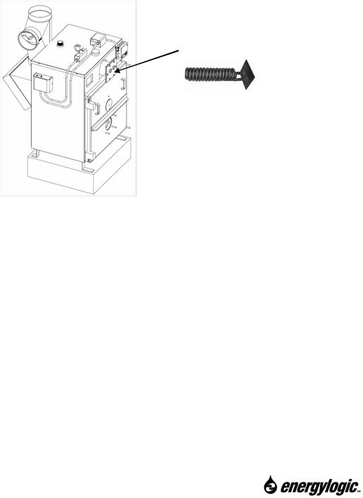
4.6 Burner/Vessel Assembly
Now, the burner can be installed on the boiler vessel. This is done as follows:
 The burner assembly is heavy. Handle with care.
1.Remove the four (4) nuts from the studs on the boiler door
2.Install the burner gasket onto the studs. NOTE: Gasket sealer should not be used on this gasket. Apply a thin film of anti-seize compound to the vessel side of the burner gasket to help reduce gasket sticking when servicing.
3.Inspect the retention head and electrodes for proper settings (refer to Section 8.5.6).
4.Mount the burner assembly onto the vessel by inserting the burner over the studs.
5.Reinstall and tighten the four (4) nuts.
6.Plug the burner harness into the vessel wiring box (refer to figure). The plug fits only one way. This completes this step for the EL-200B. If you are installing an EL-375B or EL-500B, continue to step 7 to connect the preheater to the burner. 
Always unplug the burner before doing any service work on it. Attempting to swing the vessel door open while the burner is plugged in may damage the plug or cable.
24
Call 1-615-471-5290 for Technical Support
 Loading...