

EnergyLogic 75H Operation Manual
Installation & Operation
Manual
Multi-Fuel Waste-Oil Heater Model
75H
115V/60Hz
Designed to save. Built to last.™
4109 Capital Circle
Janesville, WI 53546
www.energylogic.com
1-800-351-0643
Item #: 98030118 Rev. A
Issue Date: 28 May 2020

i
Call 1-800-351-0643 for Technical Support
Caution!
Before you begin installation and operation
of your heater, read this manual completely,
and save it for future reference!
IMPROPER INSTALLATION, OPERATION, OR
MAINTENANCE OF THE HEATER SYSTEM CAN CREATE
HAZARDOUS CONDITIONS AND WILL VOID THE
WARRANTY
• This heater is UL listed for commercial and industrial use only.
• Refer to safety information and precautions in this manual.
• Installation of the unit shall be made in accordance with all state and local codes which
may differ from information provided in this manual. Installations in Canada shall be in
accordance with the regulations of authorities having jurisdiction and installation
practice shall be made according to CSA standard B139, Installation Code for Oil
Burning Equipment.
• Product improvements are occurring regularly, so the products may vary slightly from
what is shown in this manual.
• If you have any questions or concerns during the installation or operation of the heater,
contact your local service representative or EnergyLogic.
Thank you for purchasing an EnergyLogic heater. Record your Unit I.D. number below for
future reference. Please register your unit to activate the warranty by visiting EnergyLogic’s
website at www.energylogic.com/register . If you have any issues with registering, please
contact us at the number below.
Unit I.D. #:
(Six digit number located on
the side of the cabinet)
Installed By:
(Service Company, Address,
Contact Name, Phone Number)
Date of Installation:
ii
Call 1-800-351-0643 for Technical Support
Table of Contents
Before you begin ................................................................................................................................... i
Table of Contents ................................................................................................................................... ii
1. Safety, Codes and Regulations ......................................................................................................... 4
1.1 General Warnings ......................................................................................................................... 4
1.2 Safety Hazards ............................................................................................................................. 5
1.3 Codes and Regulations ................................................................................................................ 7
1.4 Fuels and Fuel Management ........................................................................................................ 8
1.5 Clearances to Combustible Surfaces ............................................................................................ 9
2. Installation Considerations .............................................................................................................. 10
2.1 Technical Guidelines .................................................................................................................. 10
2.2 Heater Placement Guide ............................................................................................................ 10
2.3 Drain Valve Installation…………………………………………………………………………………...11
3. Exhaust Flue System Installation .................................................................................................... 12
3.1 Barometric Damper Tee Installation ............................................................................................ 12
3.2 Flue Piping Installation ................................................................................................................ 12
3.3 Draft Gauge Installation (included with some packages) ............................................................. 15
4. Electrical System Installation ........................................................................................................... 16
4.1 Wall Thermostat (Standard) ........................................................................................................ 16
4.2 Main Electrical Connection ......................................................................................................... 17
5. Startup and Operation ..................................................................................................................... 18
5.1 Do’s and Don’ts/Tech Tips .......................................................................................................... 18
5.2 Burner Primary Control Operation .............................................................................................. 18
5.3 Safety Systems and Warnings .................................................................................................... 19
5.4 Heater Startup ............................................................................................................................ 20
5.4.1 Priming and Starting the Heater ........................................................................................... 20
5.4.2 Burner System Checkout……………………………………………………………………………21
5.5 Everyday Operation of Your EnergyLogic Used Oil Heater ......................................................... 24
6. Maintenance ................................................................................................................................... 25
6.1 Service Contracts ....................................................................................................................... 25
6.2 Safety Warnings – Lockout/Tagout ................................ ............................................................. 25
6.3 Monitoring System Performance over Time ................................................................................ 25

iii
Call 1-800-351-0643 for Technical Support
6.4 Maintenance Procedures ............................................................................................................ 26
6.4.1 Heat Exchanger Cleaning .................................................................................................... 27
6.4.2 Fan Cleaning ........................................................................................................................ 29
6.4.3 Nozzle Line Assembly Cleaning ........................................................................................... 30
6.4.4 Air Compressor Maintenance ............................................................................................... 34
6.4.5 Oil Filter Cleaning…………………………………………………………………………………….36
7. Troubleshooting .............................................................................................................................. 37
8. Appendices……………………………………………………………………………………………………39
8.1 Wiring Diagram……………………………………………………………………………………………39
8.2 Heater Specifications……………………………………………………………………………………..41
8.3 75H Heater Maintenance Schedule and Log .............................................................................. 42
8.4 Limited Warranty ………………………………………………………………………………………….43
4
Call 1-800-351-0643 for Technical Support
1. Safety, Codes and Regulations
Thank you for the purchase of an EnergyLogic used oil heater. EnergyLogic heaters are designed
and tested for safe, reliable long-term operation. However, proper installation, fuel quality control,
and regular maintenance are required. Please read and understand this manual completely
before attempting to install, operate, or service the heater. Post this instruction manual and
maintain it in legible condition. If you have any questions, call your local service provider or the
number below for EnergyLogic Technical Service.
1.1 General Warnings
• Do not use this product where gasoline vapors or other explosive vapors
may be present.
Do not use this product near sources of heat, sparks or open flames.
• The EnergyLogic burner is to be used only in the EnergyLogic heater
provided. Do not attempt to use the burner for other purposes.
• Do not tamper with the unit or controls – call your service technician.
• Do not attempt to use unit with broken or damaged components.
• This heater is not designed for use with ductwork.
• Do not allow unqualified personnel to install or service the heater, electrical
system, or flue system. Contact EnergyLogic for help with finding a qualified installation and
service company. Failure to install and maintain your heater properly will void your warranty
and the UL listing.
• Do not attempt to start the burner when excess fuel has accumulated inside
the heat exchanger, when the heater is full of vapor, or when the combustion chamber is
very hot.
• Do not start the burner unless all cleanout panels are secure in place.
• Turn off power to the burner when it will not be used for extended periods (weeks).
Wait 10 minutes after power has been restored for the oil to heat up, prior to turning the
thermostat up and starting the heater.
• The heater is designed to be installed on non-combustible flooring. It should
be bolted down to prevent tipping or movement that could cause the flue pipe to come
loose.
• Used oils contain heavy metallic compounds and foreign materials. When
burned, these compounds are emitted from or deposited within this heater appliance and
therefore care should be taken when using, cleaning and maintaining this equipment.
• EnergyLogic recommends that the building have a secondary heat source
during times the heater is down for maintenance or service. Used oil heaters require
maintenance. Also, used oil may sometimes be unavailable or burn poorly due to
contaminates in the oil. The heat from the secondary heater should be directed away from
the heater.
5
Call 1-800-351-0643 for Technical Support
1.2 Safety Hazards
There are potential hazards associated with operation of this or any heater. In addition to the
codes and regulations listed in the following section, general safety rules and the precautions
should be followed at all times to prevent accidents that could lead to personal injury, death, or
property damage. Only those qualified should perform the tasks. Specific safety hazards include:
Electricity: The EnergyLogic heater operates on 115V/60Hz electrical power. Turn
power off at the circuit breaker and lock it out prior to performing any work on the heater system or
any of the components. Make sure covers are in place during normal use. Use only copper
conductors.
Liquid Fuels: Used oils must be handled properly to prevent spills. Uncontained oil
leaks may contaminate the local water supply. Ensure that all national and local codes are
followed in regards to the requirements for spill containment and SPCC paperwork. Fuel leaks
pose slip/fall hazards, and pose a risk for fires. DO NOT USE GASOLINE OR ANY OIL
CONTAINING GASOLINE. Do not add any cleaning fluids or oil additives to the used oil burned in
this appliance. The use of unauthorized fuels will void the warranty and U.L. listing. See section
1.4 for a list of allowable fuels. The end user of the heater is responsible for ensuring that all
correct precautions are taken in managing their used oil.
Combustion Exhaust Gases: The exhaust products from the combustion are
dangerous to breathe. The heater must be attached to a flue which properly vents the exhaust out
of the building to the atmosphere at all times, to assure safe and proper operation of the burner. If
proper draft cannot be established, changes to the building construction or a draft inducer will be
required in order to provide adequate make-up air.
Safe Maintenance: Used oil contains mineral additives and deposits called “ash”
that will not burn. Ash collects in the heater and flue with regular use over time. Ash must be
cleaned out of the combustion chamber/heat exchanger and flue pipe on a scheduled basis.
Follow the minimum maintenance instructed in section 6. Wear proper protective clothing;
including gloves and face mask or respirator whenever any cleaning is performed, including the
cleaning of the heat exchanger, flue piping and exhaust stack.
Vapor/Dust Ignition: Do not store or use gasoline or other flammable liquids or
vapors near this heater, as they may be ignited by the burner. Do not operate the heater in dusty
or otherwise dangerous environments.
Flammable liquids: Do not create a fire or explosion hazard by using or placing
flammable liquids such as gasoline or solvents near the heater. A flammable liquid is any liquid
that has a closed-cup flash point below 100°F (37.8°C), as determined by the test procedures and
apparatus set forth in 1.7.4 of NFPA 30.
Minimum Clearance – Safe clearance to combustibles (Section 1.6) shall be
adhered to.
6
Call 1-800-351-0643 for Technical Support
Height, Weight, Guarding and General Safe Practices: The flue pipe for these
heaters are installed at heights which pose a risk for injuries due to a fall. Many of the
components are heavy, and pose the risk of injury with improper lifting and handling. Always
follow safe practices and use proper equipment. Never climb on the equipment. Do not take risks
when installing or servicing the equipment. All cover plates, enclosures, and guards must be
maintained in place at all times, except during maintenance and servicing. Failure to observe
general safety rules and to follow safety rules specific to the tools and equipment used or being
worked on may result in product/property damage, personal injury or death.

7
Call 1-800-351-0643 for Technical Support
1.3 Codes and Regulations
The installation, operation, and maintenance of the heater system in the United States must be
performed by qualified personnel in accordance with this manual and all national, state, and
local codes / regulations, as well as the following standards of the National Fire Protection
Association (NFPA):
NFPA 31 Standard for the Installation of Oil Burning Equipment
NFPA 30 Flammable and Combustible Liquids Code
NFPA 30A Code for Motor Fuel Dispensing Facilities and Repair Garages
NFPA 70 National Electric Code
NFPA 88A Standard for Parking Structures
NFPA 88B Standard for Repair Garages
NFPA 211 Standard for Chimneys, Fireplaces, Vents and Solid Fuel Burning
Appliances
These standards are available from the NFPA at www.nfpa.org.
Similarly, the installation, operation, and maintenance of the heater system in Canada must be
performed by qualified personnel in accordance with this manual and in accordance with all the
regulation authorities having jurisdiction, as well as CSA Standard B 139, Installation Code for
Oil Burning Equipment. Electrical installation in Canada shall be in accordance with the
Canadian Electrical Code, Part I. CSA standards are available at www.csa.ca.
A qualified installer is an individual or agency who is responsible for the installation and
adjustment of the equipment and who is properly trained and licensed to install oil burning
equipment in accordance with all codes and ordinances.
In the United States, make sure you comply with all EPA regulations concerning the gathering
and storing of used oil, and operation of the heater. Specifically, CFR Title 40 Part 279 covers
managing used oil. As well, make sure you comply with local codes and regulations.
In Canada, only used oil generated on the premises of the owner may be used in this
equipment unless written authorization is obtained from the regulatory authority. Comply with
Canadian regulations regarding the management and storing of used oil, as well as any local
codes and authorities having jurisdiction.
8
Call 1-800-351-0643 for Technical Support
1.4 Fuels and Fuel Management
The heater system is composed of several components and subsystems that work together for
efficient and safe operation. In order for the system to function as designed, good fuel
management practice must be followed.
The 75H heater is listed by Underwriters’ Laboratories (U.L.) for the U.S. and Canada,
operating on the following fuels:
• Used Crankcase Oil.
• Used Automatic Transmission Fluid.
• ASTM D396 No. 2 Fuel Oil.
DO NOT USE GASOLINE OR ANY OIL CONTAINING GASOLINE.
Fuel mixtures must have a minimum flash point of 140°F (60°C) and the maximum flash point
of approximately 400°F (204°C). Mixtures shall not contain hazardous waste.
Never mix inappropriate or hazardous material with the used oil. Examples of
substances that should never be added include but are not limited to:
• Gasoline
• Hazardous Waste
• Anti-freeze
• Carburetor Cleaner
• Paint Thinner
• Any Chlorinated Material
• Parts Washer Solvents
• Oil Additives
• Animal Fats
• Vegetable/Cooking Oils
The addition of inappropriate substances to the fuel is not approved and can
lead to poor equipment performance, premature product failure, and/or explosive/hazardous
conditions. Burning of fuels that contain unapproved substances will void the product warranty
and the UL listing. If you have any question about what is contained in your used oil, it is your
responsibility to have the oil analyzed prior to burning.
Contact Technical Support at the number below if you have questions about a particular fuel
type, or if you need fuel analysis. For a nominal fee, Technical Support will provide a
professional fuel analysis. You will be provided with instructions in order to collect an oil
sample to be sent out for analysis.
9
Call 1-800-351-0643 for Technical Support
1.5 Clearances to Combustible Surfaces
It is of the utmost importance that the installation conforms to the minimum
clearances to combustible surfaces (Material made of or surfaced with wood, compressed
paper, plant fibers, plastics, or other material that can ignite and burn, whether flame proofed
or not, or whether plastered or unplastered). Consult applicable codes and regulations for
precedence. Non-compliance to minimum clearances may result in fire, explosion, personal
injury or death. Minimum Clearances per U.L. Listing:
Front - 24", Sides - 18", Rear - 6", Flue Pipe (Single Wall) - 18"
18” (46 cm) from outer
surface of single-wall flue
tee/pipe in all directions.
6” (45.7 cm) from rear of cabinet.
24” (61 cm) from
front of cabinet.
18” (46 cm) from sides.
Mount to non-combustible flooring.
Minimum Clearances to Combustible Surfaces
NOTE: These are the minimum allowed clearances for fire safety. Leaving additional access space
around the unit will make periodic maintenance easier.

10
Call 1-800-351-0643 for Technical Support
2. Installation
EnergyLogic heaters are designed to operate reliably over a wide range of conditions.
However, proper installation is required to prevent unnecessary rework or problems.
2.1 Technical Guidelines
1. All components of your heater are factory-tested to ensure proper operation. Do not
tamper with controls.
2. Pre-assembled fittings are sealed and do not require additional tightening.
3. Always supply power through a hard-wired connection (3 wires: line, neutral and
ground), 115 VAC/60 Hz - single phase power, 14 AWG minimum wire size (copper
conductors only) protected by a 10 Amp circuit breaker (15 Amp Max).
Electricity is very dangerous. Wiring must be installed by a qualified electrician.
In the U.S., consult the National Electric Code (NEC) and local building codes for additional
requirements. In Canada, consult the Canadian Electrical Code, Part I.
4. Locate the heater indoors, in a dry area, with the louvers pointed into the center of the
space to be heated. The heater is not designed to be used with ductwork.
5. Maximize the vertical run of flue and avoid horizontal runs. Allow access for clean-out.
6. Mount the wall thermostat to an interior wall. Do not allow it to hang by the wiring
harness. Do not mount it to the heater cabinet.
7. Another source of heat is recommended for periods when the heater may be off-line
for maintenance or for any other reason.
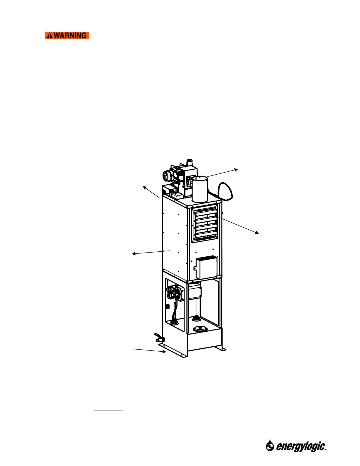
2.2 Heater Placement
It is important to plan the heater and flue prior to installation.
Electrical Wiring - Will the layout of your building allow safe routing and installation of
electrical wiring to the heater? Check national and local building codes.
Flue Pipe - Is ceiling/roof or wall location suitable for a flue pipe to pass through? Are any
obstacles or flammable materials present at interior or exterior locations? Check your roof
warranty about penetration for the flue pipe. Check your local building and fire codes.
Combustion and Make Up Air Requirements – Ensure that adequate air for safe combustion
is provided for all fuel-burning appliances and equipment in the space. Do not locate the heater
in a small, enclosed space, such as a closet. Refer to NFPA 31, chapter 5 for requirements. In
Canada, reference CSA Standard B139/CGA B149.
11
Call 1-800-351-0643 for Technical Support
Minimum Clearance –
Safe clearances to combustibles (Section 1.5) shall be adhered to.
Distance from Flammable Liquids –
Do not create a fire or explosion hazard by using or placing flammable liquids
such as gasoline or solvents near the heater. A flammable liquid is any liquid that has a
closed-cup flash point below 100°F (37.8°C), as determined by the test procedures and
apparatus set forth in 1.7.4 of NFPA 30.
POWER TO THE HEATER SHOULD BE SHUT OFF ANYTIME FLAMMABLE VAPORS
MAY BE PRESENT!
Access - Position the heater where there is adequate clearance for operating and maintaining
the unit. Leave an unobstructed path for shop vehicles and equipment. Consider access
needed for service (heat exchanger cleaning, flue cleaning, removal of caps and baffle, burner
access, etc.).
Cabinet Orientation vs. Air Flow Direction – Consider the workspace to be heated.
Consider proximity to windows, doors, etc.
Structural Requirements (Canada) – In Canada, the structure in which the used oil burning
appliance is housed shall be no less than 4.6m (15ft) high at the point where the appliance is
situated and have a minimum length and width of 6m (20ft) and a minimum floor area of 37m
2
(400ft2). In addition, the installation including flue stack height requirements and distance from
property line shall be in accordance with the authorities having jurisdiction concerning
environmental quality as well as fuel, fire, and electrical safety and Table 7 in CSA B140.0-03
(clause 22.3.2).
Do not attach or install ductwork to the outlet of the heater cabinet.
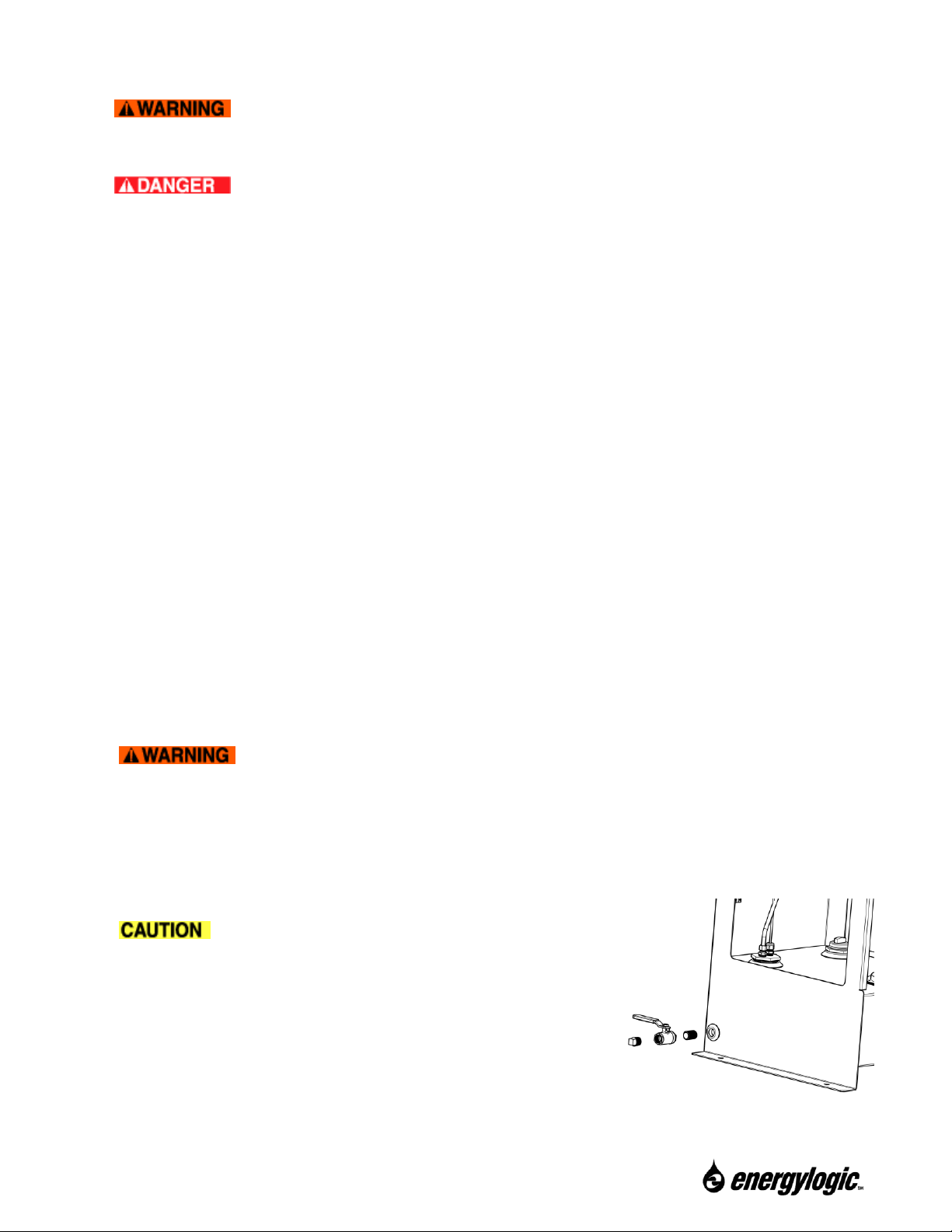
2.3 Drain Valve Installation
The drain valve and fittings are not installed at the factory to prevent damage during shipping.
Install the drain valve in the port on the side of the tank as shown in the figure. Use the thread
sealant provided. Do NOT use Teflon tape.
The drain valve is necessary for draining
water from the bottom of the tank. The drain valve is
shown in closed position in figure. The plug should be
installed in the drain valve to prevent spills if the valve is
accidentally opened.
12
Call 1-800-351-0643 for Technical Support
3. Exhaust Flue System Installation
The exhaust system is critical for the safe operation of the heater, as it exhausts the products
of combustion out of the building to the ambient environment. Because the exhaust gas is
much hotter than the outside air, it will naturally rise through the flue and create a negative
pressure behind it. This is commonly referred to as “draft”.
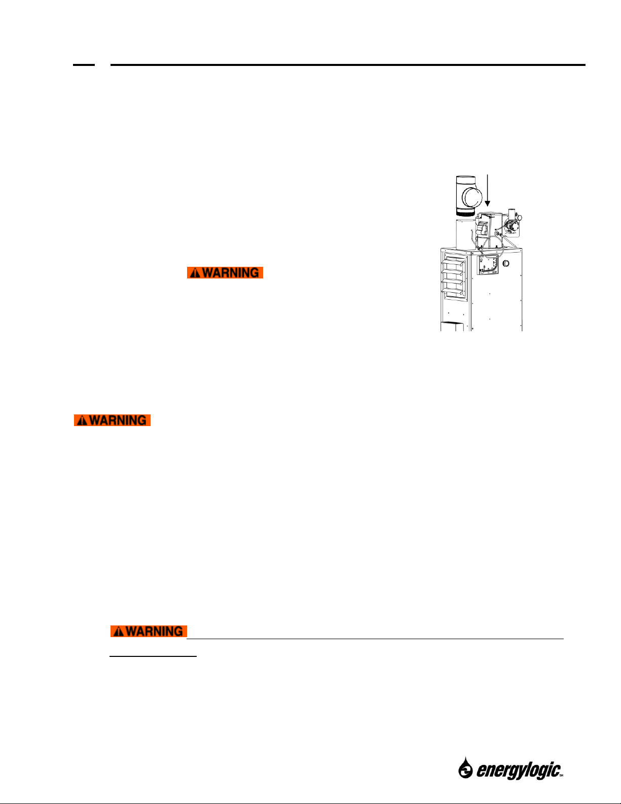
3.1 Barometric Damper Tee Installation
The barometric damper tee helps to regulate draft
pressure through varying ambient conditions.
Install the tee with the tapered end pointing
downward by sliding it into the heat exchanger
outlet until snug (refer to figure). Secure using 3
sheet metal screws. Do NOT
operate the heater without a Tee and Damper for
draft control.
3.2 Flue Piping Installation
The flue piping exhausts products of combustion
out of the building into the ambient environment.
Insert Tee with
taper end down.
Damper Tee Installation
You may have a basic knowledge of carpentry and the use of hand tools.
However, it is important that you review all safety rules in this section, and all safety rules in
the manuals provided with your manufactured flue kit. If you have any doubt about your ability
to complete the installation in a safe and workmanlike manner, you should arrange for a
professional installation. For more regulatory information regarding flue pipe installation,
consult NFPA 31 and your local fire protection and building codes.
Flue System Installation Steps and Considerations:
• Review this section completely. Choose and purchase a factory-built flue kit that
complies with U.L. standard 103 Type HT, or Equivalent.
• The 75H requires a 6-inch diameter flue and may not be reduced.
• For your convenience, the unit includes some helpful chimney-flue material. Additional
material will also be necessary.
• Read and follow the product and safety instructions included with your
selected flue kit. If product instructions were not included, contact the manufacturer of
your kit to obtain the instructions. Additional support material and videos are available at
EnergyLogic.com. If you are unsure of your ability to properly install the flue system,
hire a professional installer or contact EnergyLogic for assistance.
 Loading...