

Energy 220ws8fs/00, 220ws8fb/75, 220ws8fb/93, 220ws8fb/27, 220ws8fb/00 Service Manual
...
22” TFT LCD COLOR MONITOR
ServiceService
ServiceService
ServiceService
Service Manual
TABLE OF CONTENTS
Description
Important Safety Notice .............................................
Technical Data & Power Management .......................
Connection to PC .......................................................
OSD Menu Control Level Structure ...........................
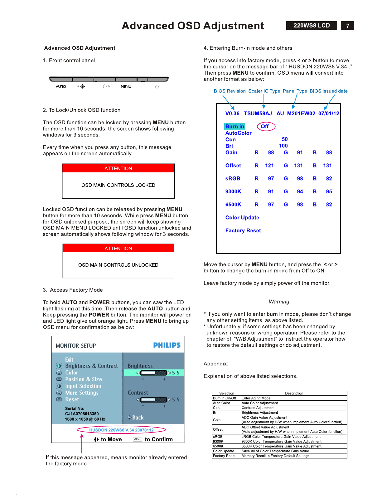
Advanced OSD Adjustment .......................................
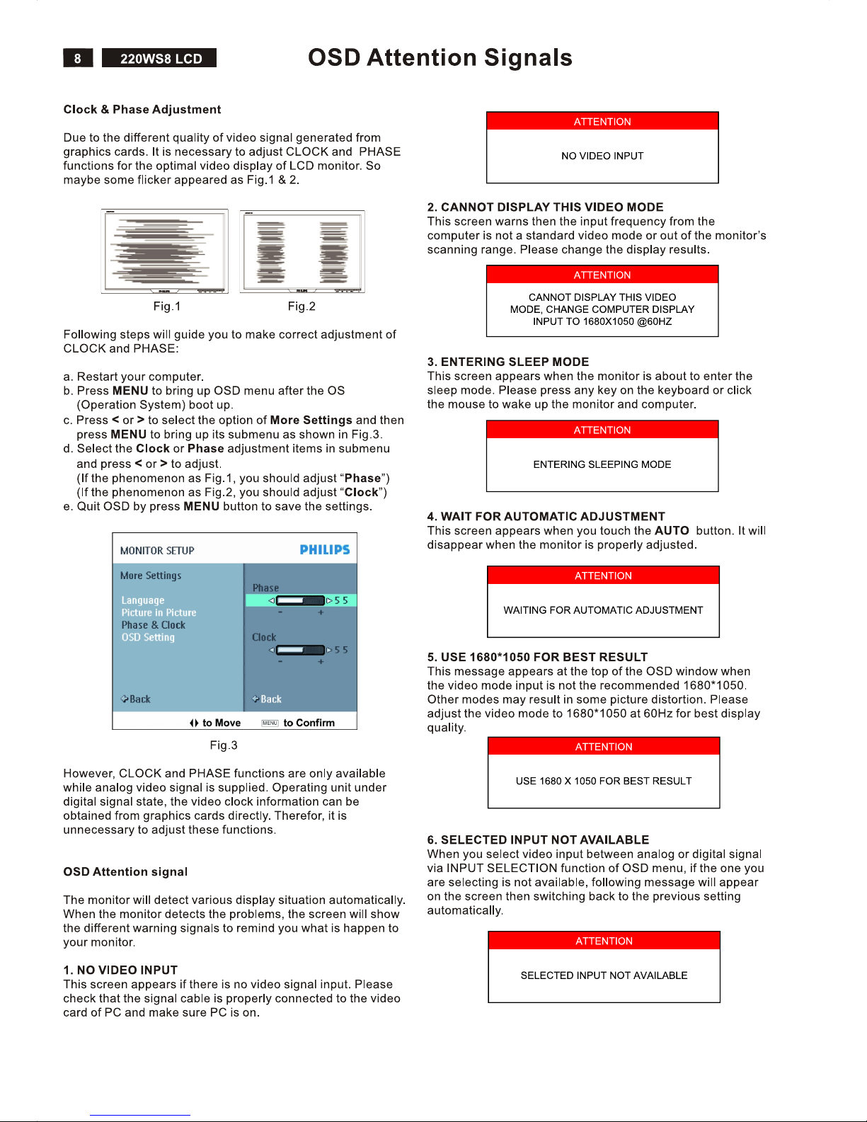
OSD Attention Signal .................................................
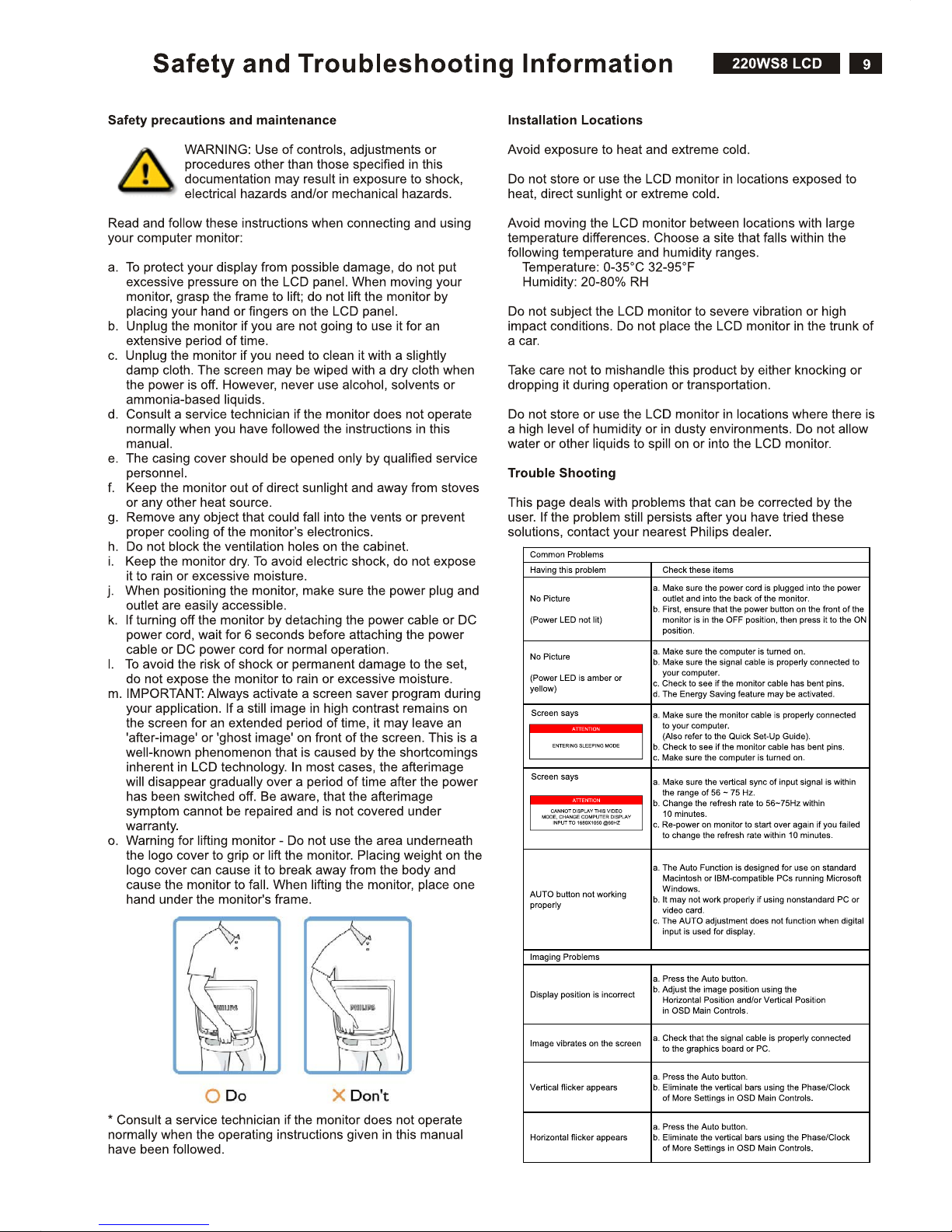
Safety and troubleshooting information ....................
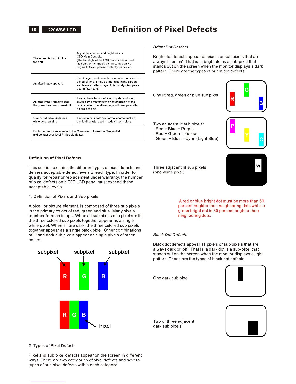
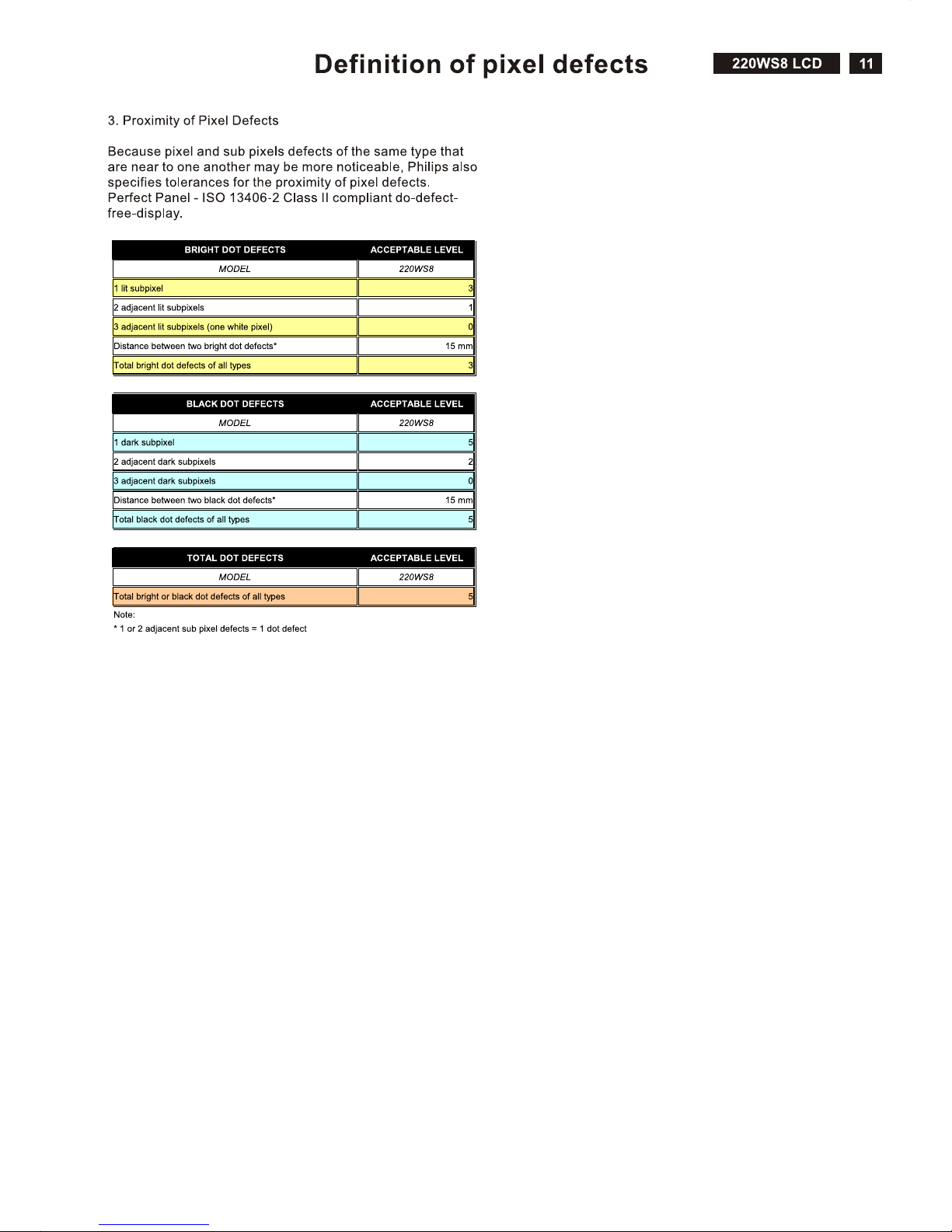
Definition of Pixel Defects ..........................................
...........
Wiring Diagram ..........................................................
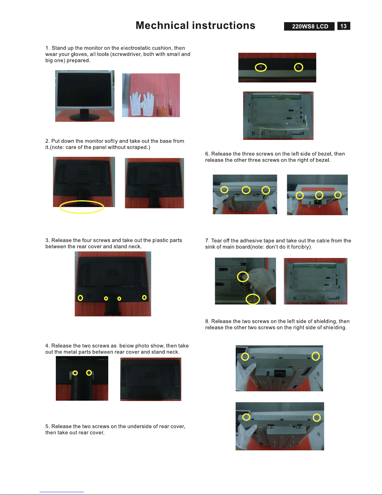
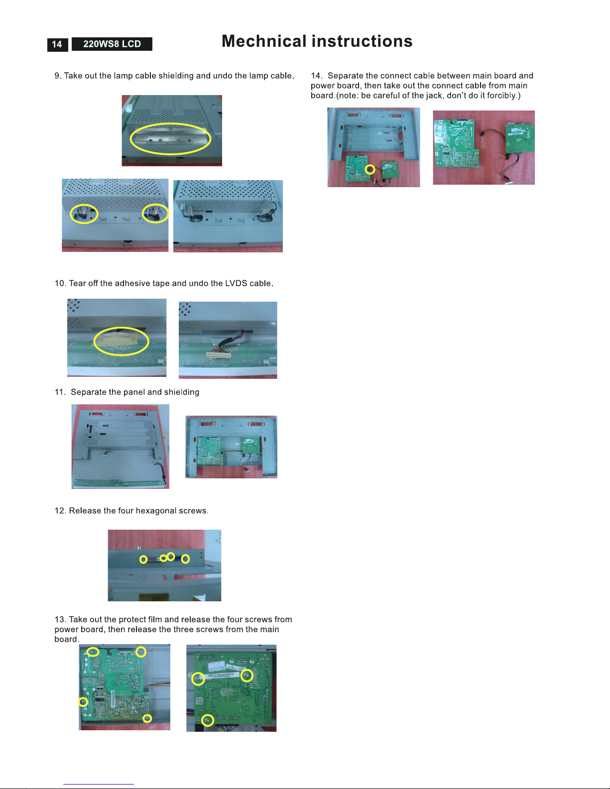
Mechanical Instructions .............................................
F/W Upload Instructions ............................................
DDC Instructions ........................................................
DDC DATA .................................................................
Safety Instructions, Warnings and Notes ........
Page
2
3~4
5
6
7
8
9
10~11
12
13~14
15~16
16~18
19~20
21
Description
Block Diagram ...........................................................
Scaler Board Schematic Diagram .............................
Power Board Schematic Diagram .............................
Button Board Schematic Diagram .............................
Scaler Board Layout Side View .................................
Power Board Layout Side View .................................
Button Board Layout Side View .................................
Exploded View ...........................................................
Recommended Parts List ..........................................
Spare Parts List .........................................................
Different Parts List .....................................................
General Trouble Shooting Guide ...............................
General Poduct Specification
Safety Check Process ...............................................
....................................
Page
22
23~27
28~29
30
31~32
33~34
35
36
37
38~39
40
41~54
70
55~69
SAFETY NOTICE
ANY PERSON ATTEMPTING TO SERVICE THIS CHASSIS MUST FAMILIARIZE HIMSELF WITH THE CHASSIS
AND BE AWARE OF THE NECESSARY SAFETY PRECAUTIONS TO BE USED WHEN SERVICING ELECTRONIC
EQUIPMENT CONTAINING HIGH VOLTAGES.
CAUTION: USE A SEPARATE ISOLATION TRANSFORMER FOR THIS UNIT WHEN SERVICING.
REFER TO BACK COVER FOR IMPORTANT SAFETY GUIDELINE.
Subject to modification Mar. 5th 2007 EN :
220WS8FS/00
220WS8FB/27
220WS8FB/00
220WS8FB/69
220WS8FB/75
220WS8FB/93

2
220WS8 LCD
Proper service and repair is important to the safe, reliable
operation of all Philips Consumer Electronics Company**
Equipment. The service procedures recommended by Philips
and described in this service manual are effective methods of
performing service operations. Some of these service
operations require the use of tools specially designed for the
purpose. The special tools should be used when and as
recommended.
It is important to note that this manual contains various
CAUTIONS and NOTICES which should be carefully read in
order to minimize the risk of personal injury to service
personnel. The possibility exists that improper service
methods may damage the equipment. It is also important to
understand that these CAUTIONS and NOTICES ARE NOT
EXHAUSTIVE. Philips could not possibly know, evaluate and
advise the service trade of all conceivable ways in which
service might be done or of the possible hazardous
consequences of each way. Consequently, Philips has not
undertaken any such broad evaluation. Accordingly , a
servicer who uses a service procedure or tool which is not
recommended by Philips must first satisfy himself thoroughly
that neither his safety nor the safe operation of the equipment
will be jeopardized by the service method selected.
* * Hereafter throughout this manual, Philips Consumer
Electronics Company will be referred to as Philips.
WARNING
Critical components having special safety characteristics are
identified with a by the Ref. No.in the parts list and
enclosed within a broken line*
(where several critical components are grouped in one
area) along with the safety symbol on the schematics or
exploded views.
Use of substitute replacement parts which do not have the
same specified safety characteristics may create shock, fire,
or other hazards.
Under no circumstances should the original design be
modified or altered without written permission from Philips.
Philips assumes no liability , express or implied, arising out of
any unauthorized modification of design.
Servicer assumes all liability .
* Broken Line
Important Safety Notice
FOR PRODUCTS CONTAINING LASER :
DANGER - In visible laser radiation when open.
AVOID DIRECT EXPOSURE TO BEAM.
CAUTION - Use of controls or adjustments or
performance of procedures other than
those specified herein may result in
hazardous radiation exposure.
CAUTION - The use of optical instruments with this
Product will increase eye hazard.
TO ENSURE THE CONTINUED RELIABILITY OF THIS
PRODUCT, USE ONLY ORIGINAL MANUFACTURER'S
REPLACEMENT PARTS, WHICH ARE LISTED WITH
THEIR PART NUMBERS IN THE PARTS LIST SECTION
OF THIS SERVICE MANUAL.
Take care during handling the LCD module with backlight
unit
- Must mount the module using mounting holes
four corners.
- Do not press on the panel, edge of the frame
electric shock as this will result in damage to the screen.
- Do not scratch or press on the panel with any sharp
such as pencil or pen as this may result in
panel.
- Protect the module from the ESD as it may damage
electronic circuit (C-MOS).
- Make certain that treatment persons body are
through wrist band.
- Do not leave the module in high temperature and in
of high humidity for a long time.
- Avoid contact with water as it may a short circuit
the module.
- If the surface of panel become dirty, please wipe it
a soft material.( Cleaning with a dirty or
damage the panel.)
arranged in
strongly or
objects,
damage to the
the
grounded
areas
within
off with
rough cloth may

220WS8 LCD
Technical Data
3
1. General Specification
1.1 Panel characteristic
Panel source
Screen type
Screen dimensions
AUO M220EW01 V0
Resolution
Outside dimensions
Pixel pitch (mm)
Color pixel arrangement
Display surface
Color depth
Backlight
View angle (CR>10)
Contrast ratio
White luminance
Color gamut
Response time
LPL LM220WE1-TLA1
Active area (mm)
Resolution
Outside dimensions
Pixel pitch (mm)
Color pixel arrangement
Display surface
Color depth
Backlight
Active area (mm)
View angle (CR>10)
Contrast ratio
White luminance
Color gamut
Response time
CMO M220Z1-L03
Resolution
Outside dimensions
Pixel pitch (mm)
Color pixel arrangement
Display surface
Color depth
Backlight
Active area (mm)
View angle (CR>10)
Contrast ratio
White luminance
Color gamut
Response time
1.2 Scanning frequencies
Horizontal scan range
Vertical scan range
1.3 Video
Video dot rate
Input impedance
(Analog signal input)
- video
- Sync
: AUO M220EW01 V0 (1st one)
: LPL LM220WE1-TLA1(2nd one)
: CMO M220Z1-L03 (3rd one)
: TN+film
: 22 inches (diagonal) 16:10
: 1680 X 1050 (WXGA+)
: 493.7 (W) X 320.1 (H) X 16.5 (D)
: 0.282 x 0.282
: R. G. B. Vertical Stripe
: Hard-coating (3H), Non-glare type
: 16.7M colors
: 4 lamps
: >= 160 for H/V (typical)
: >= 1000 : 1
: >= 300 nits (7.0mA)
: >= 72%
: 5 ms
: 473.76 (H) x 296.1(V)
: 1680 X 1050 (WXGA+)
: 493.7 (W) X 320.1 (H) X 16.5 (D)
: 0.282 x 0.282
: R. G. B. Vertical Stripe
: Hard-coating (3H), Non-glare type
: 16.7M colors
: 4 lamps
: 473.76 (H) x 296.1(V)
: >= 160 for H/V (typical)
: >= 1000 : 1
: >= 300 nits (7.0mA)
: >= 72%
: 5 ms
: 1680 X 1050 (WXGA+)
: 493.7 (W) X 320.1 (H) X 16.5 (D)
: 0.282 x 0.282
: R. G. B. Vertical Stripe
: Hard-coating (3H), Non-glare type
: 16.7M colors
: 4 lamps
: 473.76 (H) x 296.1(V)
: >= 160 for H/V (typical)
: >= 1000 : 1
: >= 300 nits (7.0mA)
: >= 72%
: 5 ms
: 30 - 93 K Hz (automatic)
: 56 - 76 Hz (automatic)
: < 165 M Hz (Over 165MHz,
Warning message will show up)
: 75 ohm
: 2.2K ohm
: 700 mVpp
: Analog R/G/B separate inputs
Separate horizontal and vertical /
Composite (H+V) TTL level,
Sync On Green (SOG) sync
0.3Vp-p Negative
: Signal TMDS link
(3 channels : Rx0 & Rx1 & RX2-/+)
: Both Analog and Digital input.
It can be switching via OSD option.
: 513.8 mm
: 416.2 mm
: 213.6 mm
:
: 565 mm
: 174 mm
: 472 mm
: 5 Kg (Including I/F cable 240g)
: - 5 ° + 2 / - 0 ° ( forward )
+ 25 ° + 0 / - 3 ° ( backward )
: nil
: nil
: nil
: AC 100 - 240 V,
: 50 / 60 + 2 Hz
: < 50W maximum, 45W (typ)
: 40
: 5 to 35 degree C
: 10% to 85% (max.)
: 0 - 3658 m
: 600 - 100 mBAR
(Recommend at 5 to 35 degree C,
Humidity less then 60%)
: -20 to 60 degree C
: 95% max
: 0 - 12192 m
: 300 - 1100 mBAR
: 50,000 Hrs
: 567 mm
: 189 mm
: 480 mm
0 to degree C
Input signal levels
Sync. input signals
Input impedance (Digital)
Video interface
1.4 Physical characteristics
Unit dimensions
- Width
- Height
- Depth
Packed unit dimensions
Weight (monitor only)
Title angel
Swivel angel
Height adjustment
Portrait display
AC input: - voltage
- frequency
Power consumption
Ambient temperature
Operating
- Temperature
- Humidity
- Altitude
- Air pressure
Storage
System MTBF
- Width
- Height
- Depth
Packed unit dimensions
(China only)
- Width
- Height
- Depth
- Temperature
- Humidity
- Altitude
- Air pressure
4
220WS8 LCD
Automatic Power Saving
If you have VESA / DPMS compliance display card or software
installed in your PC, the monitor can automatically reduce
power consumption when power saving function active. And if
an input from keyboard, mouse or other devices is detected,
the monitor will automatically wake up. The following table
shows the power consumption and signaling of this automatic
power saving feature:
This monitor must comply with the Microsoft On Now
specification, with two power management states, as defined
by the VESA DPMS document. And must appropriately display
the DPMS states. Also comply with Environmental Protection
Agency (EPA) Energy Star and TCO03 power management
standard strictly.
ENERGY STAR is a U.S. Registered mark. AS AN ENERGY
STAR PARTNER, PHILIPS HAS DETERMINED THAT THIS
PRODUCT MEETS THE ENERGY STAR GUIDELINES OF
ENERGY EFFICIENCY.
Data Storage
Factory preset mode:
This monitor has 16 factory-preset modes as indicated in the
following table:
Technical Data
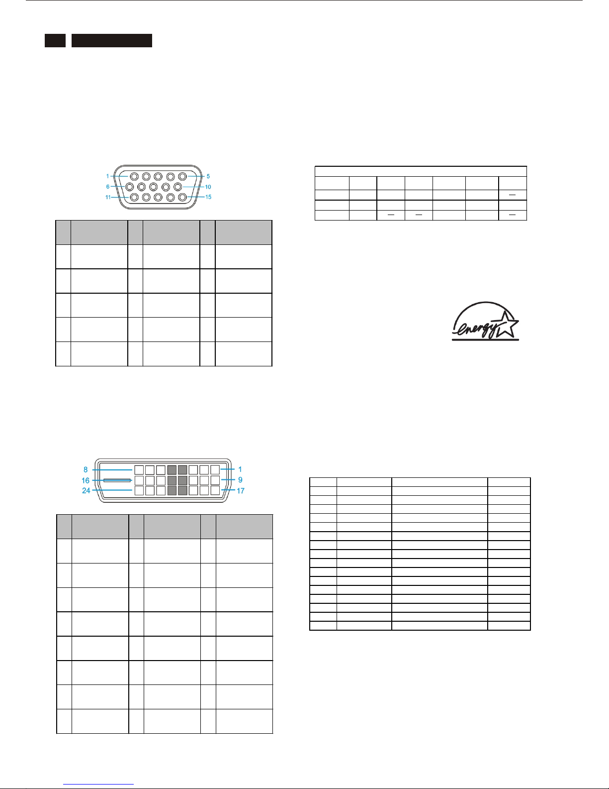
2. Pin Assignment
2.1 PC analog video input with D - sub connector.
Connector type of analog signal cable :
D - Sub male with DDC2B pin assignment.
Blue connector with thumb-operated jackscrews.
Pin assignment :
2.2 PC digital video input with DVI-D connector.
Connector type of DVI-D signal cable :
DVI-D male with DDC2B pin assignment.
White connector with thumb-operated jackscrews.
Pin assignment :
Pin
No.
Signal
Assignm ent
Pin
No.
Signal
Assignm ent
Pin
No.
Signal
Assignm ent
1 Red input 6 Red ground 11 Sense (Ground)
2
Green input
(SOG)
7 Green ground 12
Serial data line
(SDA)
3 Blue input 8 Blue ground 13 H.Sync / H + V
4 Sens e (Ground) 9 + 5 V 14
V. Sync
(VCLK for DDC)
5 Hot Plug Detect 10 Logic ground 15 Data clock line
Pin
No.
Signal
Assignm ent
Pin
No.
Signal
Assignm ent
Pin
No.
Signal
Assignm ent
1
T.M.D.S.
Data 2 -
9
T.M.D.S.
Data 1 -
17
T.M.D.S.
Data 0 -
2
T.M.D.S.
Data 2 +
10
T.M.D.S.
Data 1 +
18
T.M.D.S.
Data 0 +
3
T.M.D.S.
Data 2/4 s hield
11
T.M.D.S.
Data 1/3 s hield
19
T.M.D.S.
Data 0/5 s hield
4 No connect 12 No connect 20 N o connect
5 No connect 13 No connect 21 N o connect
6 DDC clock 14 + 5V power 22
T.M.D.S
Clock shie ld
7 DDC data 15
Ground
(for + 5V)
23
T.M.D.S.
Clock +
8 No connect 16 Hot plug detect 24
T.M.D.S.
Clock -
Mode Resolution H. freq / v. freq Standard
1 640 X 350 31.469 K Hz / 70.090 Hz VGA
2 720 X 400 31.468 K Hz / 70.085 Hz VGA
3 640 X 480 31.500 K Hz / 59.940 Hz VGA
4 640 X 480 35.000 K Hz / 67.000 Hz Macintosh
5 640 X 480 37.500 K Hz / 75.000 Hz VESA
6 688 X 556 31.250 K Hz / 50.000 Hz Macintosh
7 800 X 600 35.156 K Hz / 56.250 Hz VESA
8 800 X 600 37.879 K Hz / 60.317 Hz VESA
9 800 X 600 46.875 K Hz / 75.000 Hz VESA
10 1024 X 768 48.363 K Hz / 60.004 Hz VESA
11 1024 X 768 60.023 K Hz / 75.000 Hz VESA
12 1152 X 870 68.700 K Hz / 75.000 Hz Macintosh
13 1280 X 1024 63.981 K Hz / 60.020 Hz VESA
14 1280 X 1024 79.976 K Hz / 75.025 Hz VESA
15 1600 X 1200 75.000 K Hz / 60.000 Hz VESA
16 1680 X 1050 65.290 K Hz / 59.954 Hz VESA
VESA'S mode VIDEO H-SYNC V -SYNC
Power
Consumption
Indication Rec. Time
ON Ac tive ON ON < 50 W Green LED
OFF Blanked OFF OFF < 1 W Amber LED < 3 S
Sw itch off OFF < 1 W LED OFF
Power Management Definition
Power cord VGA cable EDFU CD
DVI cable (Optional)
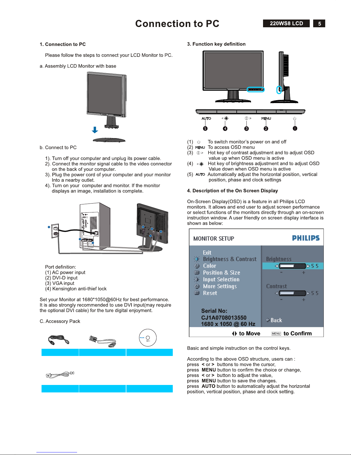
1
1
2
3
4
2
3
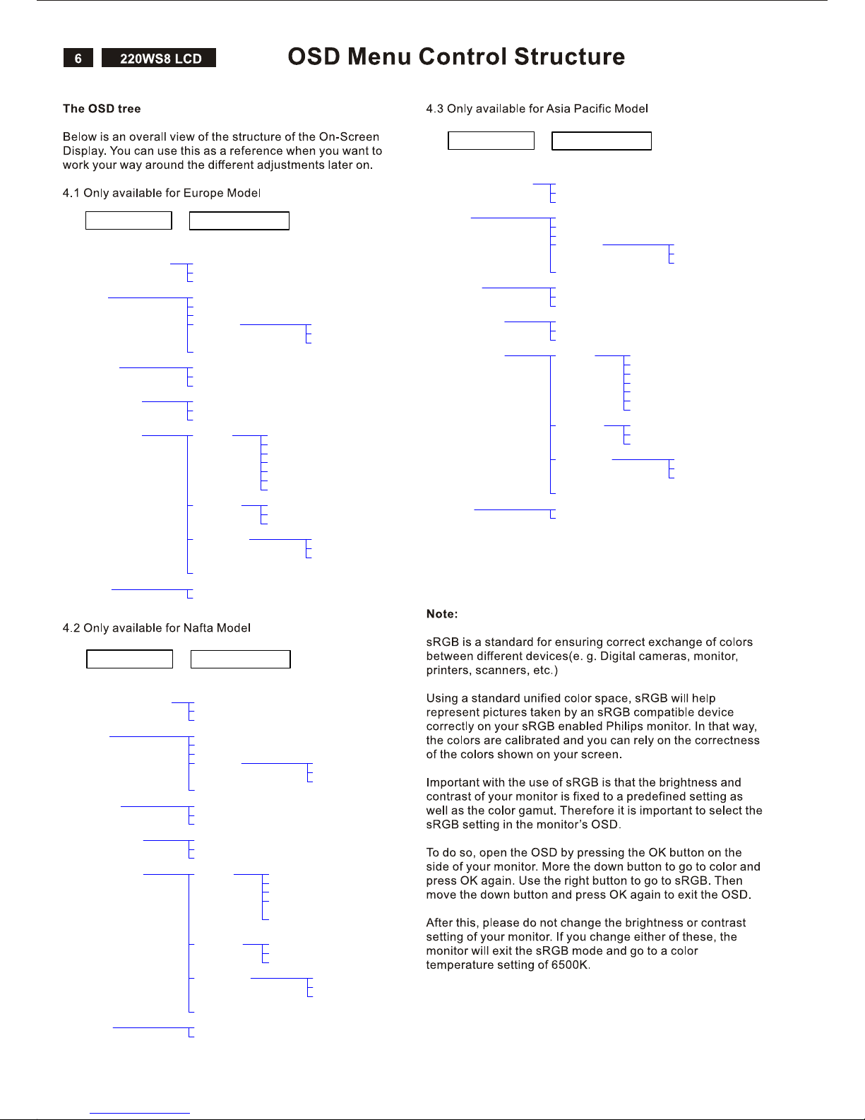
Brightness & Contrast Brightness
Color
Position
Input selection
More Settings
Main Menu (1st Level)
Sub Menu (2nd Level)
Contrast
Back
9300K
Original Color
6500K
User Define
Back
Red
Green
Blue
Exit
Horizontal
Vertical
Back
Analog
Digital
Back
Language English
Français
Deutsch
Italiano
Back
Phase/Clock Phase
Clock
Back
OSD Settings Horizontal
Vertical
Back
Back
oNteseR
Yes
Español
Русский
Brightness & Contrast Brightness
Color
Position
Input selection
More Settings
Main Menu (1st Level)
Sub Menu (2nd Level)
Contrast
Back
9300K
Original Color
6500K
User Define
Back
Red
Green
Blue
Exit
Horizontal
Vertical
Back
Analog
Digital
Back
Language English
Français
Portugues
Back
Phase/Clock Phase
Clock
Back
OSD Settings Horizontal
Vertical
Back
Back
oNteseR
Yes
Español
中文
Brightness & Contrast Brightness
Color
Position
Input selection
More Settings
Main Menu (1st Level)
Sub Menu (2nd Level)
Contrast
Back
9300K
Original Color
6500K
User Define
Back
Red
Green
Blue
Exit
Horizontal
Vertical
Back
Analog
Digital
Back
Language English
Français
Deutsch
Italiano
Phase/Clock Phase
Clock
Back
OSD Settings Horizontal
Vertical
Back
Back
oNteseR
Yes
Español
中文
Back
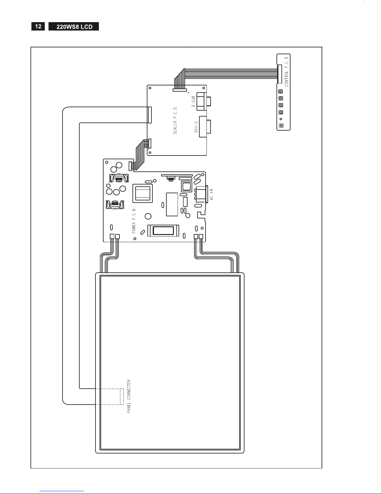
Wiring Diagram
CN2
1
2
29
30
CN78 1
CN3
CN4
CN1
7
8
1
2
CN101
CN1
CN2
CN3
CN4
CON1
1
8

220WS8 LCD
DDC Data
19
DDC DATA
THE DISPLAY DATA CHANNEL (DDC_2B) CONTENT INCLUDING:
(Digital mode)
------------------------------------------------------------------------------------EDID data ( 128 bytes )
-------------------------------------------------------------------------------------
0 1 2 3 4 5 6 7 8 9
------------------------------------------------------------------- 0 |
10 |
20 |
30 |
40 |
50 |
60 |
70 |
80 |
90 |
100 |
110 |
120 |
00
50
80
99
A9
01
27
00
51
00
38
00
20
FF
08
2F
24
40
01
40
1C
11
00
0A
FE
32
FF
01
1E
11
95
81
68
00
00
00
20
00
30
FF
5B
78
50
0F
80
B0
00
0A
FC
20
50
30
FF
C4
2E
54
95
21
36
00
20
00
20
68
57
FF
03
06
BF
00
39
00
FD
20
32
20
69
53
FF
20
55
EF
81
90
DA
00
20
30
20
6C
00
00
10
A5
80
C0
30
28
38
20
30
20
69
CA
41
01
57
B3
81
62
11
4B
20
57
00
70
0C
03
4A
00
40
1A
00
1F
20
53
00
73
(38-53) Standard Timing Identification:
#1: 1680 x 1050 @ 60Hz
#2: 1600 x 1200 @ 60Hz
#3: 1440 x 900 @ 75Hz
#4: 1440 x 900 @ 60Hz
#5: 1280 x 720 @ 60Hz
#6: 1280 x 960 @ 60Hz
#7: (50) not specified
#8: 1280 x 1024 @ 60Hz
(54-71) Detail Timing Description
#1: 1680x1050 Pixel Clock=146.2MHz
---------------------------------------------------------------------- Horizontal Image Size=474mm
Vertical Image Size=296mm
Refresh Mode:
Non-Interlaced Normal display, no stereo
HORIZONTAL:
Active Time = 1680 pixels
Blanking Time = 560 pixels
Sync Offset = 104 pixels
Sync Pulse Width = 176 pixels
Border = 0 pixels Frequency = 65.3 kHz
VERTICAL:
Active Time = 1050 lines
Blanking Time = 39 lines
Sync Offset = 3 lines Sync Pulse Width = 6 lines
Border = 0 lines Frequency = 60.0 Hz
Sync configuration: Digital separate, V(+), H(-)
(72-89) Monitor Description:
---------------------------------------------------------------------- Monitor Range Limits:
Vertical Frequency (min) = 56Hz
Vertical Frequency (max) = 75Hz
Horizontal Frequency (min) = 31KHz
Horizontal Frequency (max) = 81KHz
Maximum Supported Pixel Clock = 170MHz
(90-107) Monitor Description:
---------------------------------------------------------------------- Monitor Name: 220WS8
(108-125) Monitor Description:
---------------------------------------------------------------------- ASCII Data String: Philips 220WS
(127) Checksum OK.
(08-09) ID Manufacturer Name................................... = PHL
(10-11) Product ID Code............................... = 0850 - (2128)
(12-15) Last 5 Digits of Serial Number.................... = Error
(16) Week of Manufacture........................................ = 32
(17) Year of Manufacture...................................... = 2006
(10-17) Complete Serial Number......................... = ERROR
(18) EDID Structure Version Number........................ = 1
(19) EDID Structure Revision Number...................... = 3
(20) VIDEO INPUT DEFINITION : =
Digital signal, 0.700V/0.300V (1.000 Vp-p)
(21) Maximum Horizontal Image Size............. = 470mm
(22) Maximum Vertical Image Size.................. = 300mm
(23) Display Gamma............................................. = 2.20
(24) DPMS Supported Feature: = Active Off.
Display type = RGB color display
(25-34) CHROMA INFO:
Red x = 0.645 Green x = 0.290 Blue x = 0.142
White x = 0.313
Red y = 0.340 Green y = 0.600 Blue y = 0.067
White y = 0.329
(35) ESTABLISHED TIMING I:
720 x 400 @ 70Hz (VGA, IBM)
640 x 480 @ 60Hz (VESA)
640 x 480 @ 67Hz (MAC II, Apple)
640 x 480 @ 72Hz (VESA)
640 x 480 @ 75Hz (VESA)
800 x 600 @ 56Hz (VESA)
800 x 600 @ 60Hz (VESA)
(36) ESTABLISHED TIMING II:
800 x 600 @ 72Hz (VESA)
800 x 600 @ 75Hz (VESA)
832 x 624 @ 75Hz (MAC II, Apple)
1024 x 768 @ 60Hz (VESA)
1024 x 768 @ 70Hz (VESA)
1024 x 768 @ 75Hz (VESA)
1280 x 1024 @ 75Hz (VESA)
(37) Manufacturer's Reserved Timing:
1152 x 870 @ 75Hz (MAC II, Apple)

20
220WS8 LCD
DDC DATA
THE DISPLAY DATA CHANNEL (DDC_2B) CONTENT INCLUDING:
(Analog mode)
------------------------------------------------------------------------------------EDID data ( 128 bytes )
-------------------------------------------------------------------------------------
0 1 2 3 4 5 6 7 8 9
------------------------------------------------------------------- 0 |
10 |
20 |
30 |
40 |
50 |
60 |
70 |
80 |
90 |
100 |
110 |
120 |
DDC Data
00
50
08
99
A9
01
27
00
51
00
38
00
20
FF
08
2F
24
40
01
40
1C
11
00
0A
FE
32
FF
7B
1E
11
95
81
68
00
00
00
20
00
30
FF
00
78
50
0F
80
B0
00
0A
FC
20
50
30
FF
00
2E
54
95
21
36
00
20
00
20
68
57
FF
00
06
BF
00
39
00
FD
20
32
20
69
53
FF
32
55
EF
81
90
DA
00
20
30
20
6C
00
00
10
A5
80
C0
30
28
38
20
30
20
69
D8
41
01
57
B3
81
62
11
4B
20
57
00
70
0C
03
4A
00
40
1A
00
1F
20
53
00
73
(08-09) ID Manufacturer Name................................... = PHL
(10-11) Product ID Code............................... = 0850 - (2128)
(12-15) Last 5 Digits of Serial Number................... = 00123
(16) Week of Manufacture........................................ = 50
(17) Year of Manufacture...................................... = 2006
(10-17) Complete Serial Number.................... = 065000123
(18) EDID Structure Version Number........................ = 1
(19) EDID Structure Revision Number...................... = 3
(20) VIDEO INPUT DEFINITION : =
Separate Sync, Analog signal, 0.700V/0.300V
(1.000 Vp-p)
(21) Maximum Horizontal Image Size............. = 470mm
(22) Maximum Vertical Image Size.................. = 300mm
(23) Display Gamma............................................. = 2.20
(24) DPMS Supported Feature: = Active Off.
Display type = RGB color display
(25-34) CHROMA INFO:
Red x = 0.645 Green x = 0.290 Blue x = 0.142
White x = 0.313
Red y = 0.340 Green y = 0.600 Blue y = 0.067
White y = 0.329
(35) ESTABLISHED TIMING I:
720 x 400 @ 70Hz (VGA, IBM)
640 x 480 @ 60Hz (VESA)
640 x 480 @ 67Hz (MAC II, Apple)
640 x 480 @ 72Hz (VESA)
640 x 480 @ 75Hz (VESA)
800 x 600 @ 56Hz (VESA)
800 x 600 @ 60Hz (VESA)
(36) ESTABLISHED TIMING II:
800 x 600 @ 72Hz (VESA)
800 x 600 @ 75Hz (VESA)
832 x 624 @ 75Hz (MAC II, Apple)
1024 x 768 @ 60Hz (VESA)
1024 x 768 @ 70Hz (VESA)
1024 x 768 @ 75Hz (VESA)
1280 x 1024 @ 75Hz (VESA)
(37) Manufacturer's Reserved Timing:
1152 x 870 @ 75Hz (MAC II, Apple)
(38-53) Standard Timing Identification:
#1: 1680 x 1050 @ 60Hz
#2: 1600 x 1200 @ 60Hz
#3: 1440 x 900 @ 75Hz
#4: 1440 x 900 @ 60Hz
#5: 1280 x 720 @ 60Hz
#6: 1280 x 960 @ 60Hz
#7: (50) not specified
#8: 1280 x 1024 @ 60Hz
(54-71) Detail Timing Description
#1: 1680x1050 Pixel Clock=146.2MHz
---------------------------------------------------------------------- Horizontal Image Size=474mm
Vertical Image Size=296mm
Refresh Mode:
Non-Interlaced Normal display, no stereo
HORIZONTAL:
Active Time = 1680 pixels
Blanking Time = 560 pixels
Sync Offset = 104 pixels
Sync Pulse Width = 176 pixels
Border = 0 pixels Frequency = 65.3 kHz
VERTICAL:
Active Time = 1050 lines
Blanking Time = 39 lines
Sync Offset = 3 lines Sync Pulse Width = 6 lines
Border = 0 lines Frequency = 60.0 Hz
Sync configuration: Digital separate, V(+), H(-)
(72-89) Monitor Description:
---------------------------------------------------------------------- Monitor Range Limits:
Vertical Frequency (min) = 56Hz
Vertical Frequency (max) = 75Hz
Horizontal Frequency (min) = 31KHz
Horizontal Frequency (max) = 81KHz
Maximum Supported Pixel Clock = 170MHz
(90-107) Monitor Description:
---------------------------------------------------------------------- Monitor Name: 220WS8
(108-125) Monitor Description:
---------------------------------------------------------------------- ASCII Data String: Philips 220WS
(127) Checksum OK.
220WS8 LCD
Safety Instruction, Warnings and Notes
21
Safety instruction, warnings and notes
index of this chapter:
1 Safety Instructions
2 Warnings
3 Notes
1 Safety Instructions
Safety regulations require that during a repair:
a. Connect the set to the AC Power via an isolation transformer
(> 800 VA).
b. Replace safety components, indicated by the symbol ,
only by components identical to the original ones. Any other
component substitution (other than original type) may
increase risk of fire or electrical shock hazard.
Safety regulations require that after a repair, the set must be
returned in its original condition. Pay in particular attention to
the following points:
a. Route the wire trees correctly and fix them with the mounted
cable clamps.
b. Check the insulation of the AC Power lead for external
damage.
c. Check the strain relief of the AC Power cord for proper
function.
d. Check the electrical DC resistance between the AC Power
plug and the secondary side (only for sets which have a AC
Power isolated power supply):
* Unplug the AC Power cord and connect a wire between the
two pins of the AC Power plug.
* Set the AC Power switch to the "on" position (keep the AC
Power cord unplugged!).
* Measure the resistance value between the pins of the AC
Power plug and the metal shielding of the tuner or the aerial
connection on the set. The reading should be between 4.5
Mohm and 12 Mohm.
* Switch "off" the set, and remove the wire between the two
Pins of the AC Power plug.
e. Check the cabinet for defects, to avoid touching of any inner
parts by the customer.
2 Warnings
a. All ICs and many other semiconductors are susceptible to
electrostatic discharges (ESD ). Careless handling during
repair can reduce life drastically. Make sure that, during
repair,
you are connected with the same potential as the mass of the
set by a wristband with resistance. Keep components and
tools also at this same potential.
b. Be careful during measurements in the high voltage section.
c. Never replace modules or other components while the unit
is switched "on".
d. When you align the set, use plastic rather than metal tools.
This will prevent any short circuits and the danger of a circuit
becoming unstable.
3 Notes
3.1 General
Measure the voltages and waveforms with regard to the
chassis ground or hot ground, depending on the tested area of
circuitry. The voltages and waveforms shown in the diagrams
are indicative.
The semiconductors indicated in the circuit diagram and in the
parts lists, are interchangeable per position with the
semiconductors in the unit, irrespective of the type indication on
3.2 Schematic Notes
All resistor values are in ohms and the value multiplier is often
used to indicate the decimal point location (e.g. 2K2 indicates
2.2 Kohm).
Resistor values with no multiplier may be indicated with either
an "E" or an "R" (e.g. 220E or 220R indicates 220 ohm).
-6
All capacitor values are given in micro-farads ( X10 ),
-9 -12
nano-farads (n= X10 ), or pico-farads (p= X10 ).
Capacitor values may also use the value multiplier as the
decimal point indication (e.g. 2p2 indicates 2.2 pF).
An "asterisk" (*) indicates component usage varies. Refer to the
diversity tables for the correct values.
The correct component values are listed in the Electrical
Replacement Parts List. Therefore, always check this list when
there is any doubt.
3.3 Lead Free Solder
Philips CE is going to produce lead-free sets (PBF) from
1.1.2005 onwards.
Lead-free sets will be indicated by the PHILIPS-lead-free logo
on the Printed Wiring Boards (PWB):
This sign normally has a diameter of 6 mm, but if there is less
space on a board also 3 mm is possible.
In case of doubt wether the board is lead-free or not (or with
mixed technologies), you can use the following method:
* Always use the highest temperature to solder, when using
SAC305 (see also instructions below).
* De-solder thoroughly (clean solder joints to avoid mix of
two alloys).
Caution: For BGA-ICs, you must use the correct temperature
profile, which is coupled to the 12NC. For an overview of these
profiles, visit the website
You will find this and more technical information within the
"Magazine", chapter "Workshop information".
For additional questions please contact your local repair desk.
Due to lead-free technology some rules have to be respected
by the workshop during a repair:
Use only lead-free soldering tin Philips SAC305 with order code
0622 149 00106. If lead-free solder paste is required, please
contact the manufacturer of your soldering equipment.
In general, use of solder paste within workshops should be
avoided because paste is not easy to store and to handle.
Use only adequate solder tools applicable for lead-free
soldering tin. The solder tool must be able
- To reach at least a solder-tip temperature of 400 degree C.
- To stabilise the adjusted temperature at the solder-tip.
- To exchange solder-tips for different applications.
http://www.atyourservice.ce.philips.com/
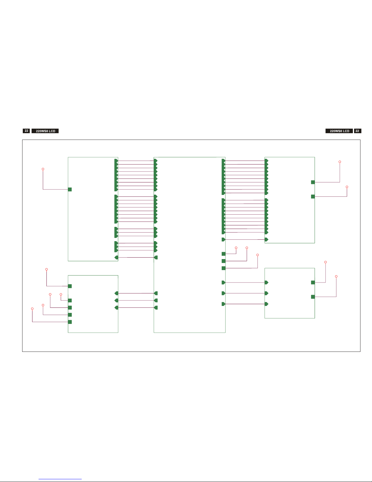
A2
2.POWER
on_BACKLIGHT
Adj_BACKLIGHT
VCC1.8
VCC3.3
+5V
VCC12
VCTRL
PC5V
A4
4.SCALER
DDCD_SDA
CLKDDCA_SDA
VSYNC
HSYNC
LVACKP
DDCD_SCL
DET_VGA
on_PANEL
DDCA_SCL
LVA3M
+5V
VCC3.3
VCC1.8
RIN
GNDG
GIN
BIN
GNDB
SOG
GNDR
R+
R-
G-
B+
B-
G+
CLK+
on_BACKLIGHT
Adj_BACKLIGHT
LVA3P
LVA2M
LVACKM
LVA2P
LVA1P
LVA1M
LVA0M
LVA0P
LVBCKP
LVB1P
LVB0P
LVBCKM
LBA2M
LVB3P
LVB0M
LVB2P
LVB1M
LVB3M
HPD_CTRL
DET_DVI
VCTRL
MUTE
VOLUME
STBY
A5
5.PANEL
LVB1M
LVB0M
LVB2P
LVA1M
LVB2M
LVB3M
LVA3P
LVBCKP
LVB3P
LVA1P
LVB1P
LVA0M
LVBCKM
LVA3M
LVA0P
LVB0P
LVACKP
LVA2P
LVACKM
LVA2M
on_PANEL
+5V
VCC12
A3
3.INPUT
RIN
GIN
BIN
VSYNC
GNDR
GNDG
GNDB
DET_VGA
HSYNC
SOG
DDCA_SDA
DDCA_SCL
B-
G+
G-
R-
CLK-
R+
CLK+
B+
DDCD_SDA
DDCD_SCL
PC5V
DET_DVI
HPD_CTRL
A6
6.AUDIO
VOLUME
STBY
MUTE
VCC12
VCC3.3
+5V
VCC12
+5V VCC1.8
VCC3.3
PC5V
PC5V
VCC12
+5V
VCC3.3
VCC1.8
VCC12
VCC3.3
Block Diagram
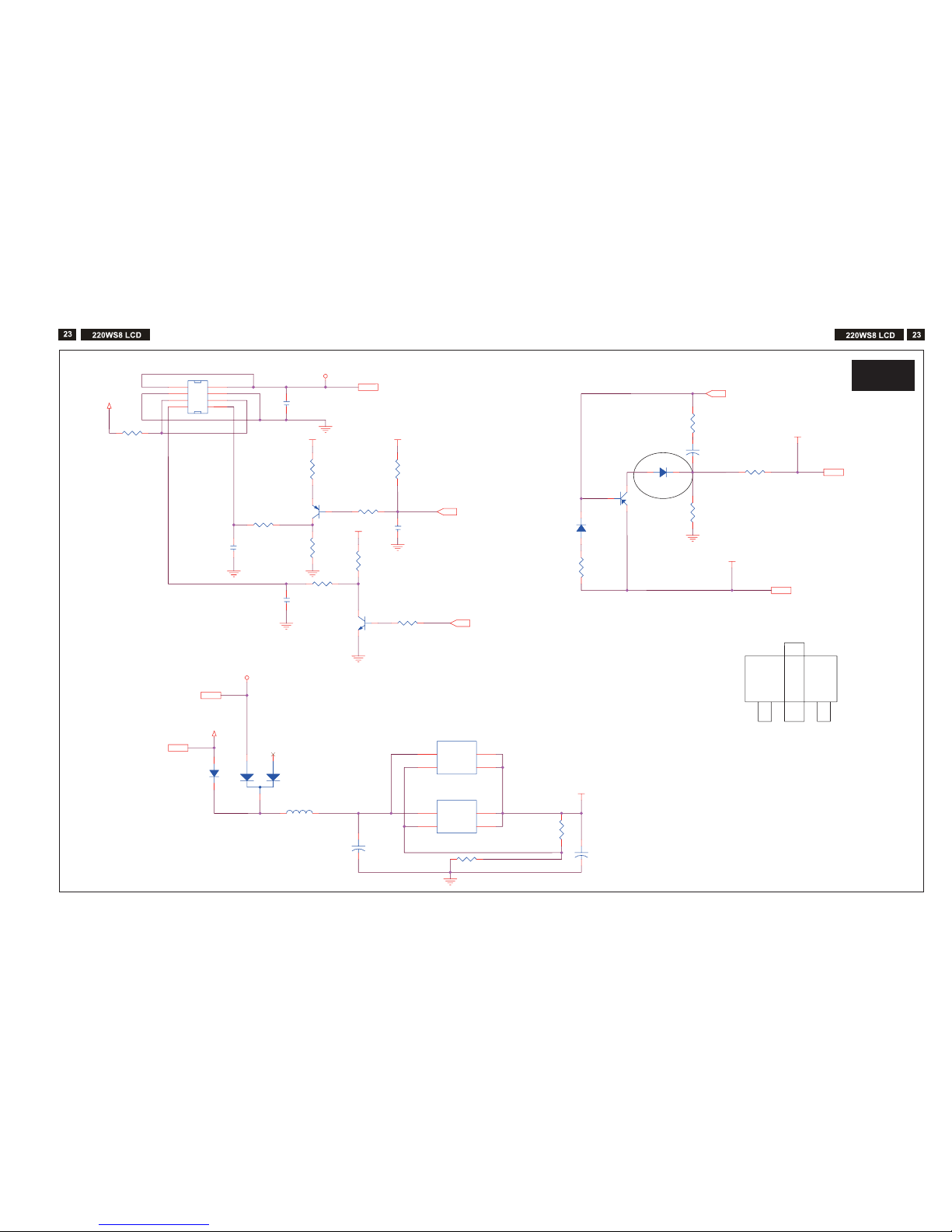
Schematic Diagram (Scaler board)
E
C
B
D1 SOT-89
VCC3.3
VCC12
VCC3.3
VCC3.3
VCC3.3
PC5V
VCC3.3
VCC1.8
+5V
+5V
R2
0/6
C
1
0.1uF/6
R10 0/6
C4
1uF/8
D1
SSM12LL
U1
LT1084/TO263
1
2
3
4
ADJ/GND
VOUT
VIN
OUT
CN1 CONN
4x2-R
4
5
6
1
2
3
8
7
R13
100/6
R9 0/6
+
C5
4.7uF/16V
R3
10K/6
L1
CX201209813/8
C3
0.1uF/6/NC
R12
2K/6
R6
10K/6
R18
330/6
1%
R8
1K/6
C6
1uF/8/NC
+
C8
330u/16V
R5 10K/6
D4
SSM12LL
R17
200/6 1%
R1
0/1206
D2
1N4148
Q3
2SB1132PT
C
B
E
+
C7
330u/16V
Q2
2N3904
3
1
2
Q1
MMST3906
D3
BAT54C-GS08
R7
47/6
U3-A1
LT1117/TO252/NC
1
2
3
4
ADJ/GND
VOUT
VIN
OUT
R4 1K/6
R11 2.2K/6
on_BACKLIGHT 4
Adj_BACKLIGHT4
VCC1.8 4
VCC3.3 4,6
+5V
3,4,5
VCC12 5,6
VCTR
L4
PC5V
3
S-A2
S-A2
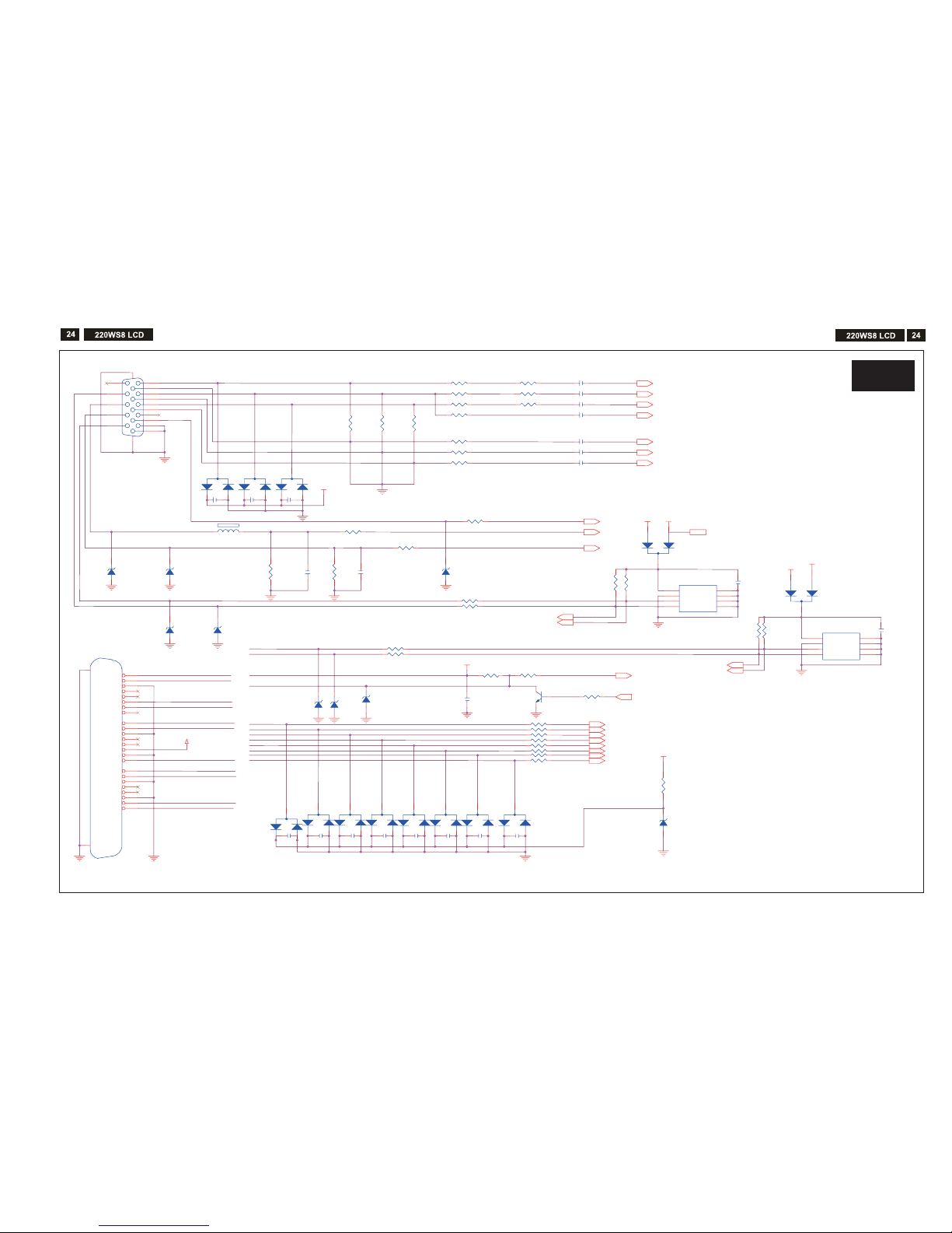
Schematic Diagram (Scaler board)
S-A3
S-A3
R
G
B
PC5V
VSI
HSI
CLK_DDC
DAT_DDC
DVI_SDA
DAT1-
DAT0DAT1+
ESD_5
V
DAT1-
DVI_S
CL
DAT2+
DAT
0+
HPD
DAT2DAT2+
DAT
0+
DAT0-
DVI_SDA
DAT2-
DVI_SCL
DCLK+
DAT1
+
HPD
DCLK-
DVI5V
DVI5V
DCLK+
DCLK-
ESD_5V
DVI5V
+5V
DVI5V
+5V
+5V
PC5V
DVI5V
C23
33pF/6
R4
9 100/6
C21 0.1uF/6/NC
C20 0.1uF/6/NC
C24
33pF/6
R48 100/6
C22 0.1uF/6/NC
R35
75/6 1%
R63
10K/
6
/NC
R58 10/6
D25
BAV99/NC
3
2
1
D6
BAV99/NC
3
2
1
C32
0.1uF/6/NC
C16 10n/6
CN4
DVI-D
1
2
3
4
5
6
7
8
9
10
11
12
13
14
15
16
17
18
19
20
21
22
23
24
RX2-
RX2+
GND
RX4-
RX4+
SCL
SDA
VS
RX1-
RX1+
GND
RX3-
RX3+
5V
GND
HP
RX0-
RX0+
GND
RX5-
RX5+
GND
RXC+
RXC-
26
25
R30 30/6 bead
R53 100/6
C13 47nF/6
D15
Z5.6V/NC
C29
0.1uF/6/NC
D22
BAV9
9/NC
3
2
1
U2
AT24C02
N-10SC/NC
1
2
3
4
5
6
7
8
A0
A1
A2
GND
SDA
SCL
WP
VCC
R34
75/6 1%
D12
BAT54C-GS
08
3
1
2
R51
10K/6
R4
7
10
K/6/NC
C1
9
47nF/6
D19
BAV9
9/NC
3
2
1
R32 30/6 bead
D5
BAV99/NC
3
2
1
C1
8
47nF/6
D23
BAV99/NC
3
2
1
R27 56/6 1%
D17
Z5.6V/NC
C2
7
0.1uF/6
D1
4
Z5.6V/NC
D13
Z5.6V/NC
C33
0.1uF/6/NC
C31
0.1uF/6/NC
D16
Z
5.6V/NC
R36
75/6 1%
C25
0.1uF/6/NC
D8
BAT54C-GS08/NC
3
1
2
R4
6
10
K/6/NC
D11
Z5.6V/NC
R6
1 10/6
D9
Z
5.6V/NC
R28 30/6 bead
R44
2.2K/6
R5
6 4.7K/6/NC
C28
0.1uF/6/NC
FB1 0/6
R3
8 100/6 1%
R60
10/6
R59 10/6
R54 10K/6
D18
BAV99/NC
3
2
1
C30
0.1uF/6/NC
D7
BAV99/NC
3
2
1
D24
BAV99/NC
3
2
1
R3
7 100/6 1%
R42 1K/6
R33 470/6
C34
0.1uF/6/NC
C17 47nF/
6
R5
5 100/6/NC
C15 47nF/6
C26
0.1uF/6
D2
6
Z3.6V/NC
C35
0.1uF/6/NC
R3
1 56/6 1%
R29 56/6 1%
CN3
VGA
1
6
2
7
3
8
4
9
5
11
12
13
14
15
10
16
17
D21
BAV99/NC
3
2
1
R39 100/6 1%
C14 47nF/6
Q6
2N3904/NC
3
1
2
R43 1K/6
R64 10/6
D20
BAV99/NC
3
2
1
D1
0
Z
5.6V/NC
R57 10/6
R41 100/6/NC
R45
2
.2K/6
R62 10/6
R65 10/6
R52 100/6
U3
AT24C02N-10SC
1
2
3
4
5
6
7
8
A0
A1
A2
GND
SDA
SCL
WP
VCC
R50
10K/6
RI
N4
GI
N4
BIN 4
VSYNC 4
GNDR 4
GND
G4
GNDB 4
DET_VGA 4
HSYNC 4
SOG 4
DDCA_SDA4
DDCA_SCL4
B- 4
G+ 4
G- 4
R- 4
CLK- 4
R+ 4
CLK
+4
B
+
4
DDCD_SDA4
DDCD_SCL
4
PC5V 2
DET_
DVI 4
HPD_CTRL 4
 Loading...