

Page 1
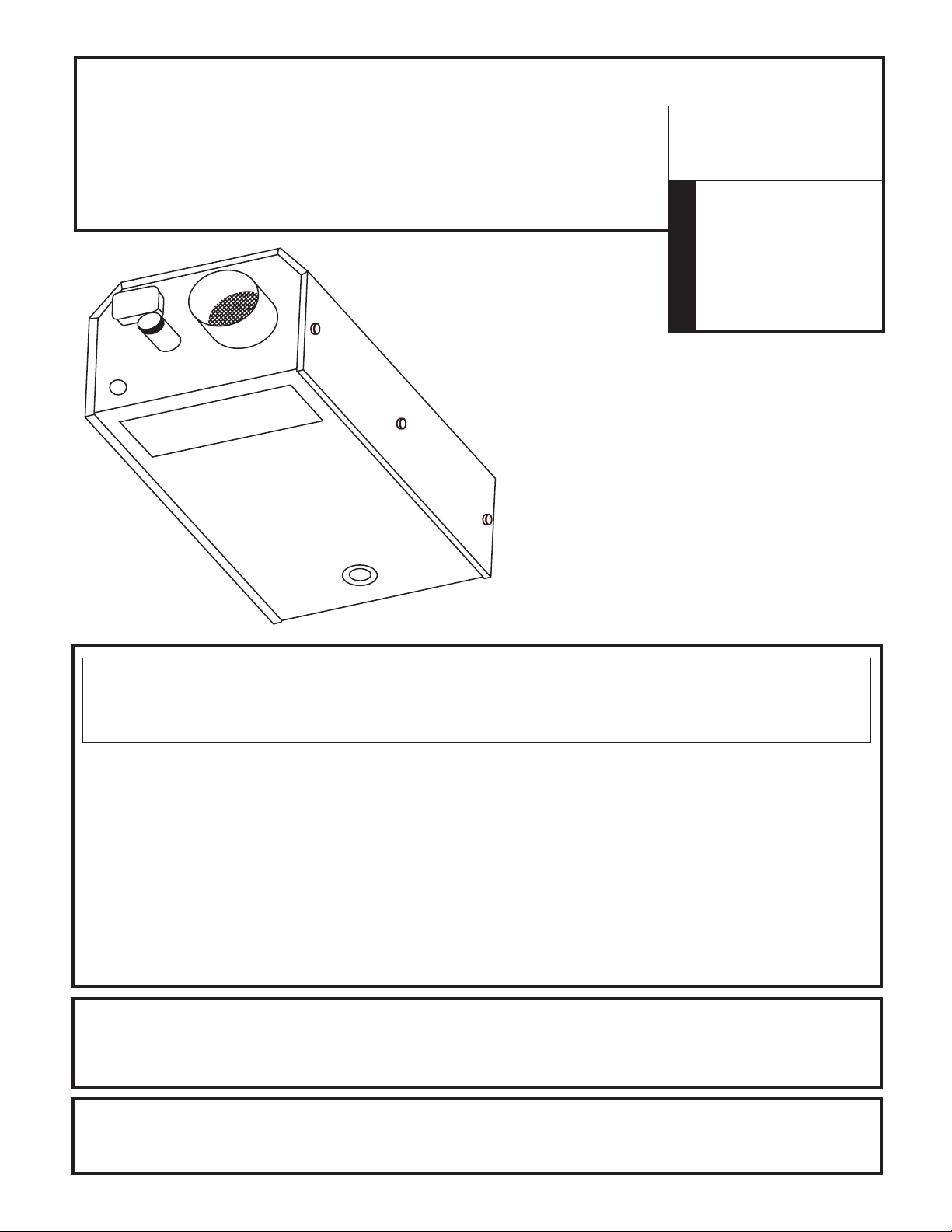
OPERATING INSTRUCTIONS AND OWNER’S MANUAL
READ INSTRUCTIONS CAREFULLY: Read and follow all instructions.
Place instructions in a safe place for future reference. Do not allow
anyone who has not read these instructions to assemble, light, adjust or
operate the heater.
enerRADIANT
®
Gas-Fired, Low-Intensity Infrared Heaters
approved for residential Garage/
Commercial Applications
HEATSTAR
MODEL
ERXL-60
ERXL-80 ERXL-80S
ERXL-100 ERXL-100S
ERXL-125 ERXL-125S
ERXL-150 ERXL-150L
ERXL-175 ERXL-175L
WARNING:
Improper installation, adjustment, alteration, service or maintenance
can cause injury or property damage. Refer to this manual. For assistance or
additional information consult a qualified installer, service agency or the gas supplier.
— WHAT TO DO IF YOU SMELL GAS
• Open Windows
• DO NOT try to light any appliance.
• DO NOT use electrical switches.
• DO NOT use any telephone in your house. Immediately call your local gas supplier from a
neighbor’s telephone. Follow the gas supplier’s instructions.
• Do not touch any electrical switch; do not use any phone in your building.
• Installation and service must be performed by a qualied installer, service agency or the gas
supplier.
• If you cannot reach your gas supplier, call the Fire Department.
FOR YOUR SAFETY:
Do not store or use gasoline or other flammable vapors and liquids in the vicinity
of this or any other appliance.
WARNING: If the information in these instructions are not followed exactly, a fire or
explosion may result causing property damage, personal injury or loss of life.
3/08 ?????????Enerco Group, Inc., 4560 W. 160TH ST., CLEVELAND, OHIO 44135 • 216-881-5500
Page 2
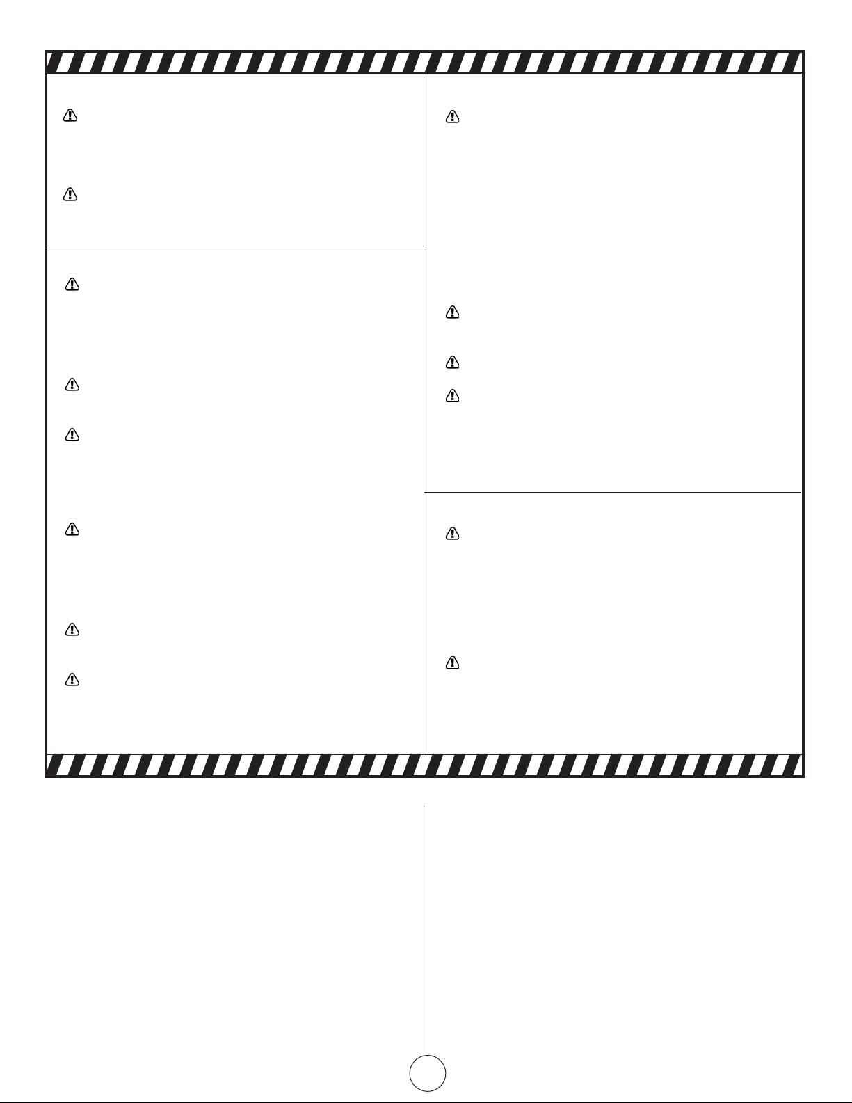
WARNING:
YOUR SAFETY IS IMPORTANT TO YOU AND TO OTHERS,
SO PLEASE READ THESE INSTRUCTIONS BEFORE YOU
OPERATE THIS HEATER.
L’AVERTISSEMENT:
Votre surete est importante a vous et donc s’il vous
plait lire ces instructions avant d’operer cet appareil de
chauffage.
GENERAL HAZARD WARNING:
FAILURE TO COMPLY WITH THE PRECAUTIONS AND
INSTRUCTIONS PROVIDED WITH THIS HEATER, CAN
RESULT IN DEATH, SERIOUS BODILY INJURY AND
PROPERTY LOSS OR DAMAGE FROM HAZARDS OF FIRE,
EXPLOSION, BURN, ASPHYXIATION, CARBON MONOXIDE POISONING, AND/OR ELECTRICAL SHOCK.
ONLY PERSONS WHO CAN UNDERSTAND AND FOLLOW
THE INSTRUCTIONS SHOULD USE OR SERVICE THIS
HEATER.
IF YOU NEED ASSISTANCE OR HEATER INFORMATION
SUCH AS AN INSTRUCTIONS MANUAL, LABELS, ETC.
CONTACT THE MANUFACTURER.
WARNING:
FIRE, BURN, INHALATION, AND EXPLOSION HAZARD.
KEEP SOLID COMBUSTIBLES, SUCH AS BUILDING
MATERIALS, PAPER OR CARDBOARD, A SAFE DISTANCE
AWAY FROM THE HEATER AS RECOMMENDED BY THE
INSTRUCTIONS NEVER USE THE HEATER IN SPACES
WHICH DO OR MAY CONTAIN VOLATILE OR AIRBORNE
COMBUSTIBLES, OR PRODUCTS SUCH AS GASOLINE,
SOLVENTS, PAINT THINNER, DUST PARTICLES OR UNKNOWN CHEMICALS.
L’AVERTISSEMENT:
Le feu, les brulures, le danger d’inhalation et explosion
garder combustibles solide tel que les materiels de
papier ou le carton.
Une distance sure eloigne de l’appareil chauffage
comme recommande.
Par les instructions, ne utiliser l’appareil de chauff-
age dans les espaces qui forme contenir combustibles
volatiil ou aeroporte, ou les produit qu’essence, les dissolvants, peindre plus mines, les particles de poussiere
ou les produits chimiques inconnus
L’AVERTISSEMENT GENERAL DE DANGER:
L’Echec pour se conformer aux precautions et aux in-
structions a fourni avec cet appareil de chauffage, avoir
pour resultat la mort blessure et la perte de propriete
ou les dommages physiques serieuses du danger de feu,
l’explosion, la brulure l’asphyxie, monoxide de carbone
empoisonant, et/ou le choc electrique.
Seulement les personnes qui peuvent comprendre et
peut suibre les instructions doivent utiliser ou doivent
entretenir cet appareil de chauffage.
Si vous avez besoin de l’information d’assistance ou ap-
pareil de chauffage telle qu’un manuel d’instruction, les
etiquettes,etc, contactez le fabricant
CONTENTS
Section 1 INTRODUCTION .............................................................. 3
Section 2 PLANNING ....................................................................3
Section 3 INSTALLATION & ASSEMBLY ..........................................12
Section 4 VENTING/DUCTING ...................................................... 16
Section 5 GAS PIPING .................................................................. 19
Section 6 WIRING ........................................................................ 20
Section 7 OPERATION MAINTENANCE ......................................... 21
Section 8 TROUBLESHOOTING ..................................................... 23
Section 9 REPLACEMENT PARTS ................................................... 24
Section 10 ENGINEERING SPECIFICATIONS ................................... 25
WARNING:
The State of California requires the following warning:
COMBUSTION BY-PRODUCTS PRODUCED WHEN US-
ING THIS PRODUCT CONTAIN CARBON MONOXIDE, A
CHEMICAL KNOWN TO THE STATE OF CALIFORNIA TO
CAUSE CANCER AND BIRTH DEFECTS (OR OTHER REPRODUCTIVE HARM).
L’AVERTISSEMENT:
L’etat de Californie exige les avertissement siuvants.
Derives de combustion ont produit en utilisant ce produit
contient monoxide de carbone, un chimique/gaz connu
dans l’etat de californie pour causer les defauts de cancer
et naissance (ou autre le mal reproducteur)
Enerco | enerRadiant® XL Series Heater Operating Instructions and Owner’s Manual
2
Page 3
SECTION 1
SECTION 2
Introduction
Ener-Radiant ERXL models are low-cost, eld assembled
infrared heaters that are easy to install and require only minimal
maintenance. They are designed to provide years of economical
operation and trouble-free service.
Checking Shipment
Check the shipment against the Bill of Lading for shortages. Also,
check for external damage to cartons. Note any shortages, and/
or external damage to cartons on the Bill of Lading in the presence
of the delivery trucker. The delivery trucker should acknowledge
any shortages or damage by initializing this “noted” Bill of Lading.
Immediately report any claims for damaged material, or shortages
that were not evident at the time of shipment, to the carrier and
your ENERCO Factory Representative.
Installer Responsibility
All heaters and associated gas piping should be installed in
accordance with applicable specications and this installation made
only by rms (or individuals) well qualied in this type of work.
Consult local building inspectors, Fire Marshals or your local ENERCO
Factory Representative for guidance.
Ener-Radiant ERXL heaters are installed on the basis of information
given in a layout drawing, which together with the cited codes and
regulations, comprise the basic information needed to complete the
installation. The installer must furnish all needed material that is not
furnished as standard equipment, and it is his responsibility to see
that such materials, as well as the installation methods he uses result
in a job that is workmanlike and in compliance with all applicable
codes.
ENERCO Factory Representatives have had training and experience
in the application of this equipment and can be called on for
suggestions about installation which can save material and money.
Planning
The following codes and instructions should be followed when
planning the installation of the Ener-Radiant ERXL heater. In addition
to these instructions, the warnings in (Section 1) must be carefully
adhered to since improper installation may lead to property damage,
injury, or death.
National Standards and Applicable
Codes
Gas Codes: The type of gas appearing on the nameplate
must be the type of gas used. Installation must
comply with local codes and recommendations
of the local gas company, and the National
Fuel Gas Code, ANSI Z223.1 – latest revision,
(same as NFPA Bulletin 54).
• Clearance between the heater and its vent
and adjacent combustible material (which
is part of the building or its contents) shall
be maintained to conform with the Stan-
dard for Installation of Gas Appliances
and Gas Piping, NFPA-54 / ANSI Z223.1 –
latest revision, National Fuel Gas Code.
Aircraft Hangers: Installation in aircraft hangers must be in
accordance with the Standard for Aircraft
Hangers, ANSI / NFPA-409 – latest revision.
• Heaters in aircraft storage or service
areas shall be installed at a height of 10
feet above the upper surface of wings or
engine enclosures of the highest aircraft
which may be housed in the hanger. (This
should be measured from the bottom of
the heater to the wing or engine enclosure, whichever is highest from the oor.)
• In other sections of aircraft hangers, such
as shops or ofces, heaters must not be
installed less than 8 feet above the oor.
• Heaters installed in aircraft hangers shall
be located so as not to be subject to damage by aircraft, cranes, moveable scaffolding or other objects.
Public Garages: Installations in garages must be made in
accordance with the Standard for Parking
Structures, NFPA-88A – latest revision or the
Standard for Repair Garages, NFPA-88B –
latest revision.
• Heaters must not be installed less than 8
feet above the oor. Minimum clearances
to combustibles must be maintained from
vehicles parked below the heater.
Operating Instructions and Owner’s ManualEnerco | enerRadiant® XL Series Heater
3
Page 4
• When installed over hoists, minimum
clearances to combustibles must be maintained from the uppermost point on the
hoist.
Electrical: The heater must be electrically grounded in
accordance with the National Electrical Code,
ANSI / NFPA-70 – latest revision. Wiring must
conform to the most current National Electrical
Code, local ordinances, and any special
diagrams furnished.
Venting: The venting must be installed in accordance
with NFPA-54 / ANSI Z223.1 – latest revision,
National Fuel Gas Code. Partial information
with regard to this code is provided in
(Section 5) of this installation manual with
regard to size and congurations for venting
arrangements.
• Any portion of ue pipe passing through
a combustible wall must be dual insulated
or have an approved thimble. Refer to
ANSI-Z223.1 – latest revision.
Hazardous
Locations: Where there is the possibility of exposure to
combustible airborne material or vapor, consult
the local Fire Marshal, the re insurance
carrier or other authorities for approval of the
proposed installation.
Critical Considerations
Ener-Radiant ERXL is a suspended heater.
Therefore, its stability, exibility, and safety are
very important. Before starting installation,
be sure the system can meet the following
requirements.
• Maintain specied clearances to combustibles, and safe distance from the heatsensitive material, equipment and work
stations.
• Provide a suspension with vertical length
of chain or swinging rod which has at
least 2 inches of horizontal travel for
each burner in a straight run. Be sure the
suspension system is sufciently exible to
accommodate thermal expansion which
occurs as the system heats up (see
Figure 5 on page 15).
• Be sure the heater has a downward pitch
of one-half inch per 20 feet away from the
burner.
• Provide signs in storage areas to specify
maximum stacking height to maintain
required clearances to combustibles.
• Plan location supports (see Figure ?).
Locate a support near all elbows.
Installation Procedure
Take maximum advantage of the building
upper structure, beams, joists, purlins, etc.,
from which to suspend the heater. There is no
unique sequence for installation of the tubing.
On-site observation will usually reveal a logical
sequence. Begin the installation at the most
critical dimension. This could save time. Watch
for swinging doors, overhead cranes, car lifts,
etc. Reectors and tubing can be installed as
you move along. Carefully adjust system pitch
at each position to level the heater. Pitch down
one-half inch in 20 feet (away from burner).
Don’t Pressure test the gas line using high pressure
(greater than ½ PSIG) without closing the
high-pressure shutoff cocks. Failure to do so
will result in damage to the burners.
DO Familiarize yourself with local and national
codes.
Develop a planned procedure which will
conserve material and labor on the job.
Check to see that all material and equipment is
on the job before starting installation.
Allow for thermal expansion of the hot tube.
Install the gas connector only as shown in
instructions (see Figure 17).
Have slip joints where required between
reectors to keep them from buckling or
coming apart.
Provide 1 sq. inch of free air opening to each
1,000 BTU/hr. of heater input (but not less
than 100 sq. inches) in enclosed spaces. One
opening should be within 12 inches of the top
and one within 12 inches of the bottom of the
enclosure.
• Provide access to burners for servicing,
preferable on both sides, above and behind the burner for removal.
• Provide a minimum of 18 inches of clearance between burners and building walls.
(Always observe minimum clearances to
combustibles.)
Enerco | enerRadiant® XL Series Heater Operating Instructions and Owner’s Manual
4
Page 5

ACCESSORY PARTS LIST
Stock Number Description
10371 ................................... Thermostat 24 volt
10392 ................................... Thermostat 120 volt
17 370 ................................... Chain Kit
034 45 .................................. Turbulator 10’ Section
034 47 .................................. Turbulator 5’ Section
16401 ...................................24” Stainless Steel Flexible
Gas Connector
18677A ................................ Installation Manual
F106414 ............................... 180° U-Tube Accessory Kit
F106415 ............................... 90° Elbow Accessory Kit
19021 ................................... Vent Adaptor
06430 .................................. Vent Cap
F111751 Installation kit for 20’ tube heater
F111752 Installation kit for 30’ tube heater
F111753 Installation kit for 40’ tube heater
F111754 Installation kit for 50’ tube heater
F111755 Installation kit for 60’ tube heater
Installation kit includes 24-volt thermostat, vent cap, 24” stainless
steel exible gas connector, gas shutoff valve, and chair kits required
to hang heater.
Operating Instructions and Owner’s ManualEnerco | enerRadiant® XL Series Heater
5
Page 6
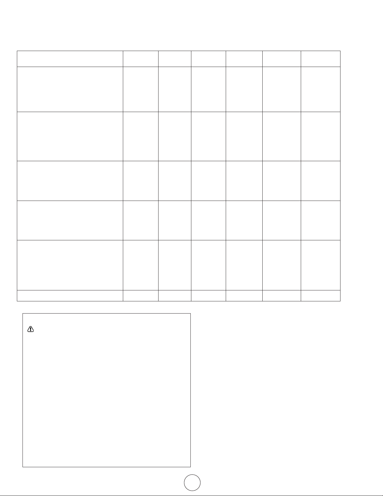
Clearances To Combustibles
TABLE 1: Minimum Clearances to Combustibles (Use Figure 1 on page 10 as a Guide)
Reflector Type Position ERXL-60 ERXL-80 ERXL-100 ERXL-125 ERXL-150 ERXL-175
Standard Reector A 6” 6” 6” 6” 6” 8”
(Horizontal) B 30” 36” 36” 36” 36” 36”
C 55” 55” 74” 87” 87” 87”
D 30” 36” 36” 36” 36” 36”
45° Reector Tilt A 12” 18” 18” 18” 18” 18”
B 30” 36” 36” 36” 36” 36”
C 55” 55” 74” 87” 87” 87”
E 36” 36” 36” 36” 36” 36”
F 60” 60” 60” 60” 60” 60”
U-Tube Standard A 6” 6” 6” 6” 6” 8”
(Horizontal) B 30” 36” 36” 36” 36” 36”
C 55” 55” 74” 87” 87” 87”
D 30” 36” 36” 36” 36” 36”
U-Tube Opposite 45° A 12” 18” 18” 18” 18” 18”
B 30” 36” 36” 36” 36” 36”
C 55” 55” 74” 87” 87” 87”
F 60” 60” 60” 60” 60” 60”
U-Tube Full 45° A 12” 18” 18” 18” 18” 18”
B 30” 36” 36” 36” 36” 36”
C 55” 55” 74” 87” 87” 87”
E 36” 36” 36” 36” 36” 36”
F 60” 60” 60” 60” 60” 60”
Unvented Above A 36” 36” 36” 36” 36” 36”
WARNING:
FIRE OR EXPLOSION HAZARD
CAN CAUSE PROPERTY DAMAGE, SEVERE INJURY OR
DEATH.
In all situations, clearances to combustibles must be maintained.
Failure to observe clearances to combustibles may result in
property damage, severe injury, or death.
Minimum clearances must be maintained from vehicles parked
below the heater. Signs should be posted in storage areas to
specify maximum stacking height to maintain required clearances
to combustibles.
Caution should be used when running the system near
combustible materials such as wood, paper, rubber, etc.
Consideration should be given to partitions, storage racks, hoists,
building construction, etc.
TABLE 1 gives minimum acceptable clearances to combustibles.
Clearances as shown in TABLE 1 are not for use in four-sided
enclosures.
Enerco | enerRadiant® XL Series Heater Operating Instructions and Owner’s Manual
6
Page 7
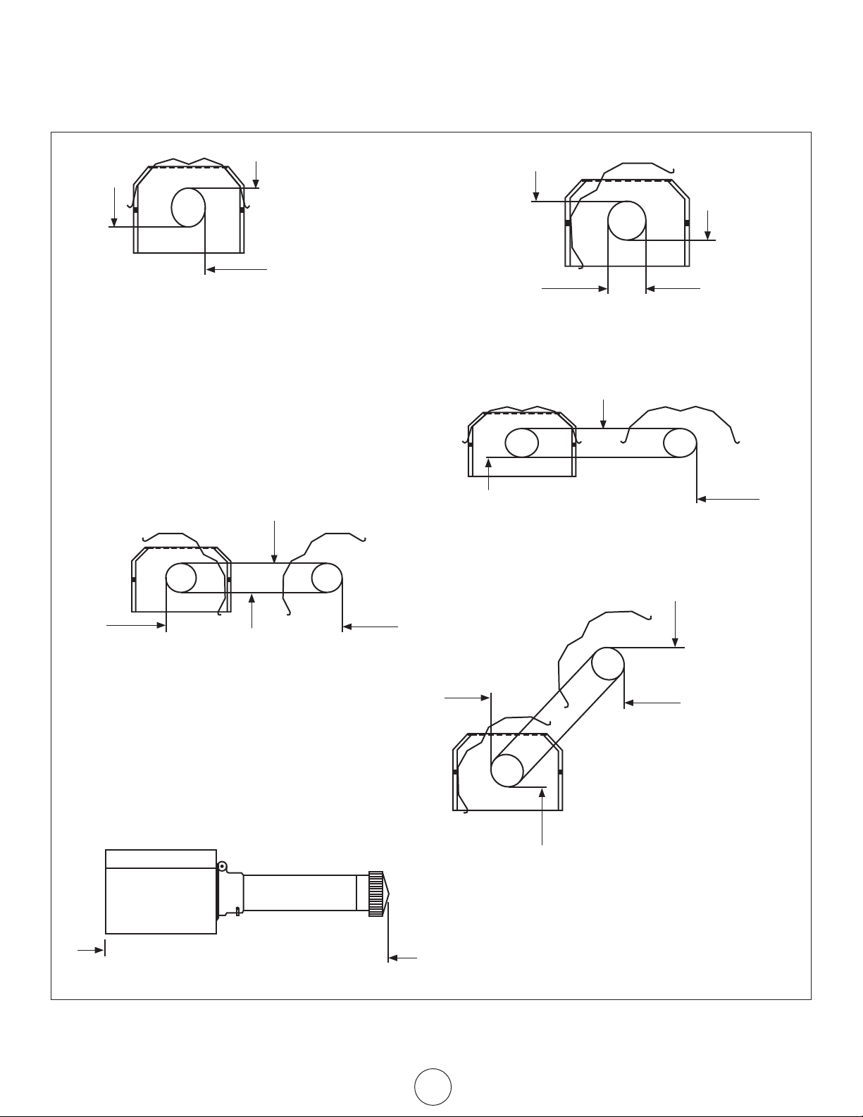
Clearances To Combustibles
FIGURE 1: Clearances To Combustibles (Refer to TABLE 1 on page 9)
C
Standard Reector
A
D
C
A
A
E
45° Reector Tilt
A
“U”-Tube, Standard
C
F
D
A
F
“U”-Tube, Opposite 45°
B
Front and Back Clearance
C
F
E
“U”-Tube, Full 45°
C
B
F
Operating Instructions and Owner’s ManualEnerco | enerRadiant® XL Series Heater
7
Page 8
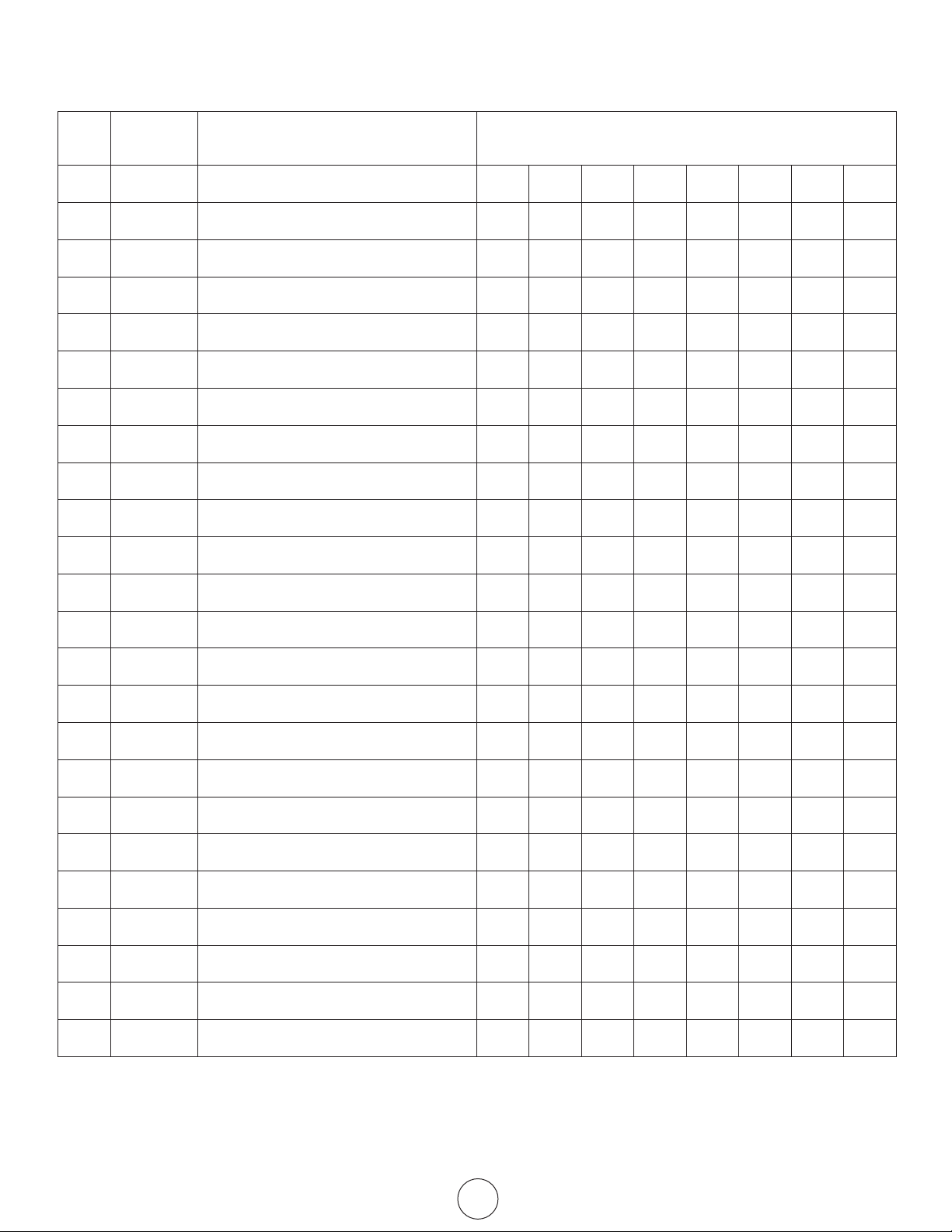
Parts List for Packaged Ener-Radiant XL Tube Heaters
Item Stock# Description Number Required
1 F107400XL ERXL-60 NG COMP / 20’ X
2 F107401XL ERXL-60 LP COMP / 20’ X
3 F107402XL ERXL-80 NG COMP / 30’ X
4 F107403XL ERXL-80 LP COMP / 30’ X
5 F107412XL ERXL-80S, NG COMP / 20’ X
6 F107413XL ERXL-80S, LP COMP / 20’ X
7 F107414XL ERXL-100S, NG COMP / 30’ X
8 F107415XL ERXL-100S, LP COMP / 30’ X
9 F102650XL ERXL-60 NG / BRN & Cont Box 1
10 F102651XL ERXL-60 LP / BRN & Cont Box 1
11 F102652XL ERXL-80S, ER3-80 LP / BRN & Cont Box 1 1
12 F102653XL ERXL-80S, ER3-80 LP / BRN & Cont Box 1 1
13 F102654XL ERXL-100S / BRN & Cont Box / NG 1
14 F102655XL ERXL-100S / BRN & Cont Box / LP 1
15 F106401XL ERXL-100S / TUBE SYS ONLY / 30’ 1 1
16 F106404XL ERXL-60, 80S / TUBE SYS ONLY / 30’ 1 1 1 1
17 F106405XL ERXL-80 / TUBE SYS ONLY / 30’ 1 1
18 00418A REFLECTOR / T.H. 2 2 3 3 2 2 3 3
19 034 45 TURBULATOR BAFFLE 10’ 1 1 1 1 1 1
20 034 47 TURBULATOR BAFFLE 5’ 1 1
21 06413 TUBE H.E. 4” O.D. X 10’ 1 1 2 2 1 1 2 2
22 14585 HANGER / TUBE & REFLECTOR 4 4 6 6 4 4 6 6
23 02753 FRONT CASING 1 1 1 1 1 1 1 1
24 14312 TUBE COUPLING ASSEMBLY 1 1 2 2 1 1 2 2
*Items 15, 16, 17 include the following items: 18, 19, 20, 21, 22, 24.
Enerco | enerRadiant® XL Series Heater Operating Instructions and Owner’s Manual
8
Page 9
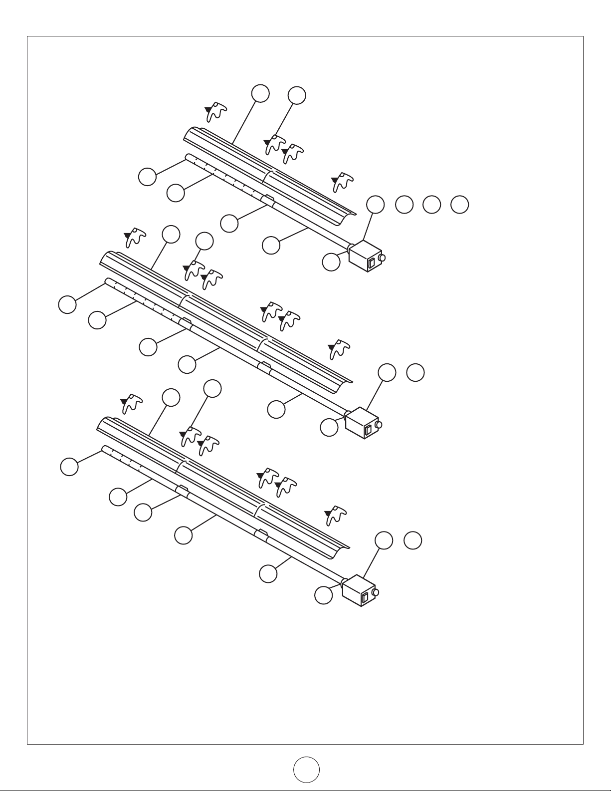
18
22
9 10 11 12
24
21
19
21
23
24
18
24
21
24
21
22
18
20
21
24
21
21
23
13 14
21
23
11 12
Figure “A” - Assembly
Model ERXL-60, ERXL-80S
Figure “B” - Assembly
Model ERXL-80
9
Figure “C” - Assembly
Model ERXL-100s
Operating Instructions and Owner’s ManualEnerco | enerRadiant® XL Series Heater
Page 10

Parts List for Packaged Ener-Radiant XL Tube Heaters
Item Stock# Description Number Required
1 F107404XL ERXL-100 NG COMP / 40’ X
2 F107405XL ERXL-100 LP COMP /40’ X
3 F107406XL ERXL-125 NG COMP / 50’ X
4 F107407XL ERXL-125 LP COMP / 50’ X
5 F107408XL ERXL-150, NG COMP / 50’ X
6 F107409XL ERXL-150, LP COMP / 50’ X
7 F107420XL ERXL-175, NG COMP / 50’ X
8 F107421XL ERXL-175, LP COMP / 50’ X
9 F107416XL ERXL-125S, LP COMP / 40’ X
10 F107417XL ERXL-125S, LP COMP / 40’ X
11 F107418XL ERXL-150L, LP COMP / 60’ X
12 F107419XL ERXL-150L, LP COMP / 60’ X
13 F107422XL ERXL-175L, LP COMP / 60’ X
14 F107423XL ERXL-175L, LP COMP / 60’ X
15 F102654XL ERXL-100 NG / BRN & Cont Box 1
16 F102655XL ERXL-100 LP / BRN & Cont Box 1
17 F102656XL ERXL-125S, ERXL-125 NG / BRN & Cont Box 1 1
18 F102657XL ERXL-125S, ERXL-125 LP / BRN & Cont Box 1 1
19 F102658XL ERXL-150L, ERXL-150 NG / BRN & Cont Box 1 1
20 F102659XL ERXL-150L, ERXL-125 LP / BRN & Cont Box 1 1
21 F102660XL ERXL-175L, ERXL-175 NG / BRN & Cont Box 1
22 F102661XL ERXL-175L, ERXL-175 LP / BRN & Cont Box 1 1
23 F106403 ERXL-150L / TUBE SYS / 60’ 1 1
24 F106406 ERXL-100, ERXL-125S / TUBE SYS / 40’ 1 1 1 1
25 F106407 ERXL-125, ERXL-150 / TUBE SYS / 50' 1 1 1 1
26 00418A REFLECTOR / T.H. 4 4 5 5 5 5 4 4 6 6
27 06413 TUBE H.E. 4” O.D. X 10’ 3 3 4 4 4 4 3 3 5 5
28 06423 TRANSITION TUDE ASSEMBLY 1 1 1 1 1 1 1 1 1 1
29 14585 HANGER / TUBE & REFLECTOR 8 8 10 10 10 10 8 8 12 12
30 14587 TUBE SUPPORT - 5' 1 1 1 1 1 1 1 1 1 1
31 14612 TUBE COUPLING ASSEMBLY 3 3 4 4 4 4 3 3 5 5
*Items 23, 24,25 include the following items: 26, 27, 28, 29, 30.
Enerco | enerRadiant® XL Series Heater Operating Instructions and Owner’s Manual
10
Page 11

28
28
27
26
28
27
26
27
30
27
29
21
19 20
22
30
27
29
21
22
30
27
29
19 20
1817
26
15 16 17 18
Figure “E” - Assembly
Model ERXL-125, ERXL-150,
ERXL-175
Figure “D” - Assembly
Model ERXL-100, ERXL-125S
Figure “F” - Assembly
Model ERXL-150L, 175L
11
Operating Instructions and Owner’s ManualEnerco | enerRadiant® XL Series Heater
Page 12

SECTION 3
HANGER HANGER HANGER HANGER
18” 18”
18” 18” 18” 18” 18” 18”
18” 18”
10’ 2-1/2”
10’ 2-1/2”
10’ 2-1/2” 10’ 2-1/2”
10’ 2-1/2”
2-1/2” OVERLAY TYP
ALUMINIZED
(4) Turbulator Sections
(1) Turbulator Adapter
(4) Turbulator Sections
(1) Turbulator Adapter
ALUMINIZED
ALUMINIZED ALUMINIZED
Installation & Assembly
FIGURE 2: Ener-Radiant XL Overview Key
Burner Housing
Must always be
installed horizontally.
Reflectors
10' 2=1/2"
Turbulator Assembly
Enerco normally ships Ener-Radiant heaters with
turbulators assembled into appropriate tubes.
Where Field Changes Occur
Turbulator Sections and Adapter are available in
sections and must be assembled before installation
(See Figure 7 for details). The number of sections
required is indicated.
Alternate overlap as shown
on overview. Length of
reector and amount of
overlap is indicated.
Tube and Reflector Hanger
Install immediately after rst
coupling.
ALUMINIZED
Tube and Reflector Hanger
Suspend system from these hangers.
Minimum two (2) required per tube.
Heat Exchange Tubes
Supplied in 10 ft. lengths.
Tube Coupling Assembly
Coupling should be oriented with slide
bar on top, and all couplings should
“point” in the same direction.
Vent Adapter
Used to attach the heat exchanger
tubing to vent pipe.
Suspensions Point
Use S-Hooks (See Figure 5) for suspension
details.
FIGURE 2a: Ener-Radiant XL Model ERXL-60, ERXL-80S, Assembly Overview
20 ft. Exchanger length. 21 ft. - 4 in. Total Heater length. 4 Suspensin points indicated.
FIGURE 2b: Ener-Radiant XL Model ERXL-80, Assembly Overview
30 ft. Exchanger length. 31 ft. - 4 in. Total Heater length. 6 Suspension points as indicated
Enerco | enerRadiant® XL Series Heater Operating Instructions and Owner’s Manual
12
Page 13

18” 18” 18” 18” 18” 18”
10’ 2-1/2”
10’ 2-1/2”
10’ 2-1/2”
(2) Turbulator Sections
(1) Turbulator Adapter
HANGER
Typ.
HANGER HANGER HANGER
ALUMINIZED ALUMINIZED
ALUMINIZED
ALUMINIZED
18”
Typ.
18”
Typ.
18”
Typ.
ALUMINIZED
ALUMINIZED
ALUMINIZED
ALUMINIZED
FIGURE 2c: Ener-Radiant XL Model ERXL-100S Assembly Overview
30 ft. Exchanger length. 31 ft. - 4 in. Total Heater length. 6 Suspension points as indicated.
FIGURE 2d: Ener-Radiant XL Model ERXL-100, ERXL-125S
40 ft. Exchanger length. 41 f t. - 4 in. Total Heater length. 8 Suspension points as indicated.
FIGURE 2e: Ener-Radiant XL Model ERXL-125, ERXL-150, ERXL-175
50 ft. Exchanger length. 51 f t. - 4 in. Total Heater length. 10 Suspension points as indicated.
FIGURE 2f: Ener-Radiant XL Model ERXL-150L, ERXL-175L
60 ft. Exchanger length. 61 f t. - 4 in. Total Heater length. 12 Suspension points as indicated.
Operating Instructions and Owner’s ManualEnerco | enerRadiant® XL Series Heater
13
Page 14

Assemble the heater components as shown
Tighten
Loosen
Hole 1
Coupling
Assembly
Impact
Block
Hole 2
in Figures 2a, 2b, 2c, 2d, 2e, and 2f. Optional
reector congurations are shown in (Figure
1). Install appropriated suspension hardware,
beam clamps, chain or rod at predetermined
locations. Adjustment of chain length will
provide uniform pitch.
Couplings: Tube and tube ttings are connected by
wrap-around couplings which clamp by means
of a tapered, hammer-driven lock member.
The starting ends of the coupling and lock
member are identied by 1/4” holes which
are put together when starting assembly. Be
sure the tube ends are in line and tube ends
butt against stop pin(s) inside coupling. The
slide bar is to be hammer-driven to a point
of securing the coupling snugly to the tubes.
Over-driving will result in distortion of the
coupling or slide bar lip to a point decreasing
the holding the capability of the coupling.
Coupling should be tight when the slide bar is
+- 2” from the end of the coupling.
(See Figure 3)
3) Attach the wire to the hole in the tab on the
adapter piece.
4) Using the wire, pull the assembled turbulator into
the tube from the opposite side.
5) Pull the turbulator through until just the tab comes
out. Detach the wire.
6) Bend the tab around the tubing. When installing
the tube, the tab will be locked in place by the
adapter.
FIGURE 4: Installation of Elbow & Coupling (optional equipment)
Elbow Package: Stk. # F106415 Elbow Package includes:
(1) elbow, (1) coupling and (1) refelctor.
Install elbow into radiant tube sequence
where plans indicate a 90° bend
(see Figure 4).
FIGURE 3: Coupling Assembly
Orient coupling so that
the impact block is above
tube centerline.
When assembling coupling note
the location of Hole 1 and Hole 2
Plain Coupling - 14612
TURBULATOR BAFFLE ASSEMBLY
INSTRUCTIONS
For ease of eld installation, the turbulator should be installed in the
tube before hanging the system.
Use the following procedure:
1) Assemble turbulator pieces by “twisting”
matching ends together.
2) Insert a long wire (11 ft. minimum) down the
length of the tube.
Elbow Fitting Dimensions
Stk. # F106414 U-Tube Package includes:
(1) U-tube, (1) coupling and (2)
reectors. Install U-tube elbow into
radiant tube sequence where plans
indicate a 180° bend
(see Figure 4).
U-Tube Fitting Dimensions 180° U-Tube
90° Elbow
Enerco | enerRadiant® XL Series Heater Operating Instructions and Owner’s Manual
14
Page 15

FIGURE 5: Typical Suspension Details
FIGURE 8: Burner Box / Transition Tube Detail
min. 3/8" (10 mm)
Locknut
Washer
Wood Beam
Screw Hook
Washer
Beam Clamp
I-Beam
As Req'd
Bar Joist Clip
Truss
S-Hook
Concrete Beam
Anchor
Chain kit - Stk. #17370
One chain kit will suspend one 10 ft. section of tube and one 10 ft.
section of reector.
FIGURE 6: Tube and Reflector Hanger
a n g l e m ou n t i n g r i n g
r a d i a n t t u b e
h o r i z o n t a l m o u n t i n g r i n g
h a n g e r
r e f l e c to r
t o p
Mounting Flange
Cap Screw
Stk. 398012
Burner Box
(ame observation
window facing down)
Gasket
Stk. #12397
Split Lock Washer
Stk. #98527
b e l o w
h o r i z o n t a l r e f l e c t o r p o s i t i o n (s t a n d a r d )
s i d e
45° re f l e c to r p o s i t i o n (o p t i o n a l )
FIGURE 7: Mounting Flange / Tube Detail
A
B
1) Insert tube 06413 into front casting to point (A).
2) Tighter set screws marked (B) until snug.
3) After both set screws are snug, turn each
additional 1/4 turn to secure tube in place.
15
Operating Instructions and Owner’s ManualEnerco | enerRadiant® XL Series Heater
Page 16

SECTION 4
Venting / Ducting
General Requirements
Heater must be vented in accordance with specication ANSI Z223.1
- latest revisions. Partial information relating to this specication is
provided in this section with regard to size and congurations for
venting arrangements (see Figures 12, 13, 14, 15, 16). For complete
information consult ANSI Z223.1 - latest revision and applicable local
codes. Use the following guidelines to help insure an adequate, safe
venting arrangement.
a) Be sure that method selected for venting
heater complies with all codes as required for
each particular location.
b) Exhaust end of heater will accept a four (4”)
inch ue pipe using the ue pipe adapter.
c) Heater may be vented to the outdoors either
vertically or horizontally.
d) If heater is to be vented horizontally:
1) Vent must exit building not less than seven (7’)
feet above grade when located adjacent to public
walkways.
2) Vent must terminate at least three (3’) feet above
any forced air inlet located within ten feet (10’).
3)Vent must terminate at least four (4’) feet below,
four (4’) feet horizontally from, or one (1’) foot
above any door, window, or gravity inlet into any
building.
4) Vent terminal shall be located at least twelve (12”)
inches from any opening through which vent gases
could enter the building.
e) Vent terminal must be beyond any combustible
overhang.
f) If condensation in the ue is a problem, the
ue length should be shortened or insulated.
g) For vent specications all of the following
conditions must be met.
1) Maximum total vent length allowed in forty-five
(45’) feet.
2) Maximum outside air supply duct allowed forty-five
(45’) feet.
3) Maximum total vent length plus outside air supply
length plus extension package shall not exceed sixty
-five (65’) feet.
4) Under length conditions 1) through 3) above — a
total of two (2) elbows are allowed for vent and
outside air supply together. Subtract fifteen (15’)
feet per additional elbow from maximum length
allowed if more than two (2) elbows are used.
Alternative Arrangements / Optional Equipment for Venting
Unvented Operation
a) Sufcient ventilation must be provided in the
amount of 4 CFM per 1,000 BTU/hr. ring rate.
b) Refer to ANSI Z223.1 - latest revision, NFPA-54
and local codes for additional information.
c) Use of optional outside combustion air is not
recommended with unvented heaters due to
pressure considerations.
Horizontal Venting
a) In combustible or noncombustible walls,
use Tjerblund VH1-4” (Stk. #19022). Follow
vent manufacturer’s instructions for proper
installation. (Alternative vent Enerco Stk.
#19023).
b) Four (4”) inch O.D. ue pipe is required. Thirty
(30’) feet maximum length is recommended.
Up to forty-ve (45’) feet maximum may
be used if insulated to prevent excess
condensation. (See General Requirements on
page 21 for additional information).
c) All ue joints should be sealed using suitable
product such as General Electric RTV106 or
Permatex Form-A-Gasket Red High Temperature
Silicone Adhesive Sealant.
d) Vent terminal should be installed at a height
sufcient to prevent blockage by snow.
e) Building materials should be protected from
degradation by ue gases.
Vertical Venting a) Four (4”) inch O.D. ue pipe, maximum
forty-ve (45’) feet in length may be used as
shown with approved vent cap. (See General
Requirements on page 21 for additional
information.)
b) An insulated thimble may be required to pass
through combustible structures (check local
codes).
c) All ue joints should be sealed using suitable
products (see recommendation for horizontal
venting.)
Draft Hood Venting
a) Refer to ANSI Z223.1 - latest revision, NFA-54
for heights and vent sizes recommended
for proper venting. (Check local codes for
additional information.)
b) Minimum six (6”) inch O.D. vent is
recommended.
Common Venting
a) Horizontal run to vent must never exceed 75%
of the vertical height of the vent. Refer to ANSI
Z223.1 - latest revision, NFA-54 for proper vent
sizes and installation.
b) Open area of common vent must equal the
sum of the open area of individual vents
connected to it. (See chart and diagrams page 25.)
c) Use double wall vent as required (check
codes.)
d) Heaters sharing a common vent must be
controlled by the same thermostat.
e) All joints must be sealed using suitable
products (see recommendation for horizontal
vent - page 24.)
f) Connections to common stack must be
positioned to avoid direct opposition between
Enerco | enerRadiant® XL Series Heater Operating Instructions and Owner’s Manual
16
Page 17

streams of combustion gases.
36”
36”
A
Outside Air Supply
a) See procedure and diagram on page ??.
FIGURE 12: Unvented Operation
FIGURE 13b: Double Wall
Double wall vent run and
Double wall terminal end
1) Ventilation equal to 4 CFM per 1,000 BTU/hr. ring
rate must be provided in unvented heater installations.
2) For dimensions A “unvented” refer to (Figure 1 —
Minimum Clearances to Combustibles.)
FIGURE 13a: Single Wall
Single wall vent run
Single wall terminal end
FIGURE 14: Vertical Venting
Operating Instructions and Owner’s ManualEnerco | enerRadiant® XL Series Heater
17
Page 18

FIGURE 15: Common Roof Venting
Approved Vent Cap
Type "B" Vent required outdoors.
SIDE VIEW
PLAN VIEW
H
Roof
Secure all joints with 3 (minimum) #8 x 3/8"
sheet metal screws and seal all joints.
Vent Adapter Stk. #19021
At least 1/4" per foot rise or pitch
must be maintained on horizontal
runs from heater to vent.
COMMON VENTING - (2) Heaters
Model # H = 6 f t. H = 8 f t. H = 15 ft.
ERXL-60 D = 7” D = 6” D = 6”
ERXL-80 D = 8” D = 7” D = 6”
ERXL-100 D = 8” D = 8” D = 7”
ERXL-125 D = 10” D = 10” D = 8”
ERXL-150 D = 10” D = 10” D = 8”
ERXL-175 D = 10” D = 10” D = 8”
Enerco | enerRadiant® XL Series Heater Operating Instructions and Owner’s Manual
COMMON VENTING - (4) Heaters
Model # H = 6 ft. H = 8 ft. H = 15 f t.
ERXL-60 D = 10” D = 10” D = 8”
ERXL-80 D = 10” D = 10” D = 10”
ERXL-100 N/A D = 12” D = 10”
ERXL-125 N/A D = 12” D = 10”
ERXL-150 N/A N/A D = 12”
ERXL-175 N/A N/A D = 12”
18
Page 19

Outside Combustion Air Supply
The Ener-Radiant XL heater is approved for installation with an
outside air supply system. Some compounds such as halogenated
hydrocarbons or other corrosive chemicals in the air can be drawn
into the equipment and cause an accelerated rate of corrosion
of some of the heater components. The use of such chemical
compounds near the enclosure should be avoided.
IMPORTANT: If the building has a slight negative pressure or
contaminants are present in the air, an outside combustion air supply
to the heaters is strongly recommended.
For an outside air supply, a four (4”) inch O.D. single wall pipe may
be attached to the heater. The duct may be up to forty-ve (45’) ft.
maximum length or two (2’) ft. minimum length with no more than
two (2) elbows. (See General Requirements in page 21 for additional
information.) An outside air supply should not be used with the draft
hood venting conguration.
The air supply duct may have to be insulated to prevent
condensation on the outer surface. The outside air terminal should
be securely fastened to the outside wall by drilling four (4) 1/4”
diameter holes in the outside ange; wood screws or bolts and
expansion sleeves may be used to fasten terminal.
FIGURE 16: Non-Pressurized Outside Air Supply Duct
SECTION 6
Gas Piping
Read applicable warnings in (Section 1) before proceeding with
Gas Pipe installation. Improper installation may result in property
damage, severe injury, or death.
Meter and service must be large enough to handle all the burners
being installed plus any other connected load. The gas line which
feed the system must be large enough to supply the required gas
with a maximum pressure drop of 1/2” water column. When gas
piping is not included in the layout drawing, the local gas supplier
will usually help in planning the gas piping.
A 1/2” tapping at each burner location must be located and oriented
as shown in (Figure 17). To check system pressure, put a plugged
1/8” NPT tapping in the gas line at the connection to the burner
farthest from the supply. Before connecting the burners to the
supply system, verify that all high pressure testing of the gas piping
has been completed. Do not high pressure test the gas piping with
the burners connected.
Follow these instructions to ensure a professional gas supply
installation:
• Support all gas piping with suitable pipe hanging
materials.
• Use wrought iron or wrought steel pipe and malleable
iron tting. All pipe ttings should be new and free
from defects. Carefully ream the pipe and tubing ends
to remove obstructions and burrs.
• Use L.P. gas-resistant joint compound on all pipe
threads.
• Check the pipe and tubing ends for leaks before
placing heating equipment into service. When
checking for gas leaks, use soap and water solution:
NEVER USE AND OPEN FLAME.
Install the ex gas connector as shown. The ex gas connector
accommodates expansion of the heating system and allows for easy
installation and service of the burner.
Outside Air Terminal: Use ACME #104 Enerco Stk. #19030.
PVC Pipe, “Dryer Hose”, or equivalent may be used instead of
standard vent pipe.
FIGURE 17: Gas Line Connection with Stainless Steel Flex Gas
Connector
Shut – off Valve
Shut-Off Valve must be parallel
to burner gas inlet. The 2”
displacement shown is for the cold
condition. This displacement may
2"
12 "
1/2" Stainless Steel Flex Gas Connector
Operating Instructions and Owner’s ManualEnerco | enerRadiant® XL Series Heater
19
Stk. #16401
reduce when the system is red.
45°
90°
0°
45°
Page 20

SECTION 6
T
H
N
120v – 60 Hz
White
Green
Supply Circuit
Burners
(Maximum – 2 per Thermostat)
Black
T
H
N
120v – 60 Hz
White
White
Green
Green
Supply Circuit
120v – 60 Hz
Supply Circuit
Burners
(Maximum – 2 per Thermostat)
Burners
(Maximum – 1 per Thermostat)
Black
Black
H
N
T
B C
W
Black
Black
White
White
Burner 3
120V – 60Hz
Supply Circuit
Burner 1
Burner 2Burner 4
White
N HN H
Red
Red/Yellow*
Purple*
Black
Green
White
G Y
3
6
5
4
2
T
Transformer Relay
VAC
120
120V
24V
Black
Black
Purple
Yellow
Yellow
Black
Black
Black
Green
Green
Orange
Transformer
White
White
White
THERMOSTAT
White
Blue
Gas Valve
Air Switch
Ignitor
Sensor
Motor / Blower
Door Switch
Terminal
Bushing
120V
L2
(NEUTRAL)
White
White
White
White
White
White
Gray
Orange
Transfomer
Thermostat
Air Switch
Gas Valve
Door Switch
Motor / Blower
Ignitor
Sensor
Blue
Yellow
Yellow
Purple
Black
Black
Black
Black
L2 (HOT)
24V
Wiring
Heaters are normally controlled by thermostats. Line voltage
thermostats are wired directly (see Figure 18a), the recommended
24V thermostats use a relay (see Figure 18b). Heaters must be
grounded in accordance with the National Electric Code ANSI/NFPA 70 - latest version. Heaters may also be controlled with a manual line
voltage switch or timer switch in place of the thermostat.
FIGURE 18a: Line Voltage Thermostat Wiring
FIGURE 18b: Low Line Voltage Thermostat Wiring
FIGURE 20: Ener-Radiant XL Burner Internal Wiring
• If any of the original wire as supplied with the
appliance must be replaced, it must be replace with
wiring material having a temperature rating of at least
105°C and 600 volts.
• Each burner must be electrically grounded in
accordance with the National Electric Code ANSI/NFPA
- 70 - latest version.
FIGURE 19: Wiring of Low Voltage Thermostat and Relay
When using 1-2 burners, use SPDT Transformer Relay / Stk. # 00172
When using 3-4 burners, use DPDT Transformer Relay / Stk. # 00183
Wires marked with an asterisk (*) are for use only with DPDT
Transformer Relay.
Enerco | enerRadiant® XL Series Heater Operating Instructions and Owner’s Manual
Low Voltage Thermostat
Stk. #10368
FIGURE 21: Ener-Radiant XL Burner Internal Wiring Ladder
Diagram
20
Page 21

SECTION 7
Operation & Maintenance
Sequence of Operation
1. Turn the thermostat up. When the thermostat calls for
heat, blower motor will energize.
2. When the motor approaches nominal running RPM,
the air proving switch closes and activates the ignition
module.
3. The ignition module then energizes the hot surface
igniter for a timed warm-up period (approximately 45
to 60 seconds.)
4. After the warm-up period, the gas valve is energized.
5. During the last part of the sequence, the igniter is deenergized and is converted to a ame sensing rod.
6. If a ame is detected, the gas valve remains open.
When the call for heat is satised, and the system
control mechanism de-energizes the burner line
voltage supply, the gas valves are turned off.
7. If no ame is detected on a single-try module, the gas
valve is closed, and the module will lockout until it is
reset. Reset is accomplished by removing power from
the module for at least ve (5) seconds (thermostat
cycle required.)
8. If no ame is detected on a three-trial module, the
gas valve is closed, and a purge period begins. After
the purge, the module acts to power the igniter for a
second warm-up period, and a second trial for ignition
period. If ame is still not established, a third and
nal purge, warm-up, and trial cycle begins. After
three trials, the module will lockout until reset. Reset is
accomplished by removing power from the module for
at least ve (5) seconds (thermostat cycle required.)
9. On a three-trial module, if ame is established and
lost on the rst or second trial, the gas valve is turned
off, a purge, warm-up, and trial for ignition will occur
on a three-trial module, only three trials for ignition
are allowed per thermostat cycle.
Maintenance
For best performance, the following maintenance procedures should
be performed before each heating season:
1. Be sure gas and electrical supply to heater are off
before performing any service or maintenance.
2. Check condition of blower scroll and motor. Dirt and
dust may be blown out with compressed air, or a
vacuum cleaner may be used.
3. Check condition of burner. Carefully remove any dust
or debris from inside the burner box or burner cup.
4. Inspect the igniter. Replace igniter if there is excessive
carbon residue, erosion, breakage or other defects.
5. Check the inside of the ring tube with a ashlight. If
carbon or scale are present, scrape out the deposits
with a wire brush or rod, or metal plate attached to a
wooden pole.
6. Check to see that the burner observation window is
clean and free of cracks or holes. Clean or replace as
necessary.
7. Check the ue pipe for soot or dirt. After cleaning as
necessary, re-attach the ue pipe to the heater.
8. Outside surfaces of heater may be cleaned by wiping
with a damp cloth.
9. A qualied service agency should be contacted for
service other than routine maintenance.
10. Check vent terminal and fresh air inlet to see that they
have not been blocked during the non-heating season.
If either pipe is restricted, the air switch won’t close,
resulting in a no-heat situation.
Troubleshooting
CAUTION: Before opening the Ener-Radiant XL
burner door for any type of service, be sure
the gas supply has been shut off at the heater
and the electrical cord from the burner box has
been unplugged.
Blower Motor 1. Is the thermostat calling for heat? Is there
Fails to Run: 115V at the burner receptacle?
2. Check blower side door for seal. Check door
switch. Replace if necessary/
3. Check blower for obstructions. Replace
blower if necessary.
Igniter 1. Check igniter for damage. Replace if
Does Not Glow: necessary.
2. Check voltage and resistance at igniter.
(Voltage should be 115V. Resistance should be
40-75 ohms.)
3. Check for obstructions to the air inlet and
outlet.
4. Check wiring and hose connections to the
air switch. Replace if necessary.
5. Check voltages at transformer primary and
secondary. Replace transformer or module if
necessary.
Valve Does Not Gas pressure downstream of gas control can
Come On: be measure by using a manometer and
connecting to pressure tap on control/
1. Check to see if manual valve heater is ON.
2. Check to see if manual valve knob on heater
gas control in ON.
3. Supply gas pressure can be checked at
1/8” NPT pressure tapping on heater external
manual valve.
4. Check to see if gas control is opening: no
manifold pressure indicates valve is closed.
If the valve is closed, either the gas valve or the
ignition module is faulty.
WARNING: Do not disconnect ground leads
inside heater. Do not interchange grounded
and ungrounded leads on transformer or
ignition module.
Burner Does Not 1. Check to see if gas lines were properly
Light: purged of air.
2. Check inlet and outlet gas pressure during
ignition period.
Natural inlet pressure should be 4.6”
21
Operating Instructions and Owner’s ManualEnerco | enerRadiant® XL Series Heater
Page 22

Natural outlet pressure should be 3.5”
LED
LP inlet pressure should be 11.0”
LP outlet pressure should be 10.25”
3. Check for proper orice and air plate.
Burner Does Not 1. Check ground wire continuity.
Stay Lit: 2. Check burner internal wiring for reversed
leads.
3. Check insulation on the igniter leads.
4. Replace module if necessary.
Honeywell Valve LED Status
The Ener-Radiant XL series Tube Heater is equipped with a honeywell
Smart Valve. This valve has a built-in diagnostic program, which will
assist in troubleshooting in the event of a valve-related problem. The
LED or (Light Emitting Diode) is located on the top of the valve as
shown in diagram below. The LED status indications are listed below
to help with the troubleshooting.
FIGURE 22:
OFF INDICATED
Off No power to the control
Bright-Dim Normal operation.
This indication shows whenever the system is
powered, unless some abnormal event has occurred.
2-Flashes Airow providing switch remains closed longer than
30 seconds after call for heat begins (air providing
switch stuck closed.)
3-Flashes Airow providing switch remains open longer than 30
seconds after combustion air blower is energized - or
blower does not energize.
4-Flashes White jumper wire is loose.
5-Flashes Flame signal sensed out of proper sequence.
6-Flashes System Lockout.
Enerco | enerRadiant® XL Series Heater Operating Instructions and Owner’s Manual
22
Page 23

SECTION 8: Troubleshooting Guide. Ener-Radiant XL
START
Turn on thermostat
Does blower turn
on?
Yes
Does the igniter
warm up and glow
red?
Yes
No
Check LED indicator on SmartValve for
indication of fault. Refer to SmartValve testing
on page ?? to determine problem.
No
Check Thermostat
and Wiring. Is the
power supply to unit
115V?
No
Find the source
of the electrical
problem
Is the air intake or
exhaust blocked?
Yes
Remove Obstruction
Check wiring and
connections
Is blower side door
Yes
No
No
in place?
Replace door
Check wiring and
hose connection to
air switch. Are they
Is the voltage at
the transformer
secondary 24V?
Is the voltage at the
transformer primary
Yes
No
Check for 115V transformer input at plug C3
on SmartValve. Check for 115V output of
C3. If no output voltage is present replace
OK?
Yes
No
115V
SmartValve.
Replace wiring and/
No
or hose connection.
Yes
Remove door. Is
voltage at door
switch 115V?
No
Check voltage at
gas valve.
Jumper wires at
pressure switch.
Does the ignitor
glow red?
Replace transformerYes
Depress switch.
Yes
Does blower come
Check voltage to
motor. Is it 115V?
Is the blower fan
obstructed?
Replace blower
Replace pressure
Yes
No
Replace SmartValve.
on?
No
Yes
No
motor.
switch.
Check door t. If
Yes
damaged, replace
Replace switch.
No
Remove obstruction
Yes
door.
After ignitor warmup period, does the
valve click?
Yes
Does the burner
light?
Yes
Check LED indicator on SmartValve for
indication of fault. Refer to SmartValve testing
No
The SmartValve checks the status of the blower proving switch contacts must see a change in the
contact with every ring cycle. Placing a jumper at the switch out of sequence will result in a fault with
No
Were the gas lines purged of air?
Check inlet gas pressure. Is pressure correct?
Refer to page 40 for correct pressure for unit.
Check inlet gas shutoff. Adjust regulator.
Contact gas supplier
Is the ignitor
damaged?
No
Check voltage at
ignitor. Is it 115V
during ignition
cycle?
the LED indicator ashing two times.
Yes
Yes
Replace ignitor.
Yes
No
Is the resistance
through igniter 40
to 75 ohms?
No
The switch on the gas valve must be in the on
No
Yes
position and the line purged of air.
Check outlet gas pressure during ignition cycle.
Is the pressure 3.5” w.c. for natural or 10.5”
w.c. for lp?
Adjust to proper pressure.
Yes
No
Check wire
connections.
on page ?? to determine problem.
Are the wires to
the SmartValve OK?
Yes
Replace SmartValve
Check for proper
Yes
burner orice and
air plate.
Replace/repair wires.
No
Does the burner
stay on?
Yes
Does the burner
run until the call
for heat ends?
If a problem still exists, contact Enerco Technical Products Customer Service
Is the continuity of
the ground wire
No
No
OK?
No
Repair wiring.
Check the continuity of the ground wire.
1-800-251-0001
Yes
Check the thermostat.
Are L1 and L2
reversed?
Yes
Repair wiring
Is the wiring at the
No
SmartValve OK?
No
Repair wiring
A fault indication of six ashes may indicate
that the ame sensing circuit is not functioning
properly. Perform the following series of checks
to correct the problem.
Operating Instructions and Owner’s ManualEnerco | enerRadiant® XL Series Heater
23
Is the insulation on
Yes
the sensor lead OK?
Repair wiring
No
Is the sensor
positioned
Yes
Is the sensor dirty?
Replace Sensor
properly?
Yes
No
No
Repair/Replace
Yes
Clean sensor.
Page 24

SECTION 9
11
9
5
6
4
7
TOP VIEW
1
11
10
9
5
6
4
7
8
3
2
TOP VIEW
SIDE VIEW
1
Replacement Parts
Item Part Number Description
1 02731 Hot Surface Igniter
2 0273 0 Flame Sensor
10413A Air Sensing Switch (ERXL-60, 80, 100, 125)
3
10414A Air Sensing Switch (ERXL-150, 175)
4 01391A Door Switch
5 02371 Burner Cup Assembly
6 07376 Motor and Blower Assembly
7 173 76 Manifold
00016 Gas Valve - Natural Gas
8
00017 Gas Valve - LP Gas
9 12404 Inspection Window
10 08364A Transformer
11 02729 Tube Flange Casting
Enerco | enerRadiant® XL Series Heater Operating Instructions and Owner’s Manual
24
Page 25

SECTION 10
Engineering Specifications
The total heating system supplied shall be design certied by the
American Gas Association and the Canadian Gas Association.
A. Burner & Burner Controls
1. Burners shall be capable of ring with one of the fuel options
as specied on the purchase documents: Natural Gas or LP.
2. Burners shall be supplied to re at any one of the input rates
as specied.
ERXL-60 60,000 BTU/Hr. ERXL-125 125,000 BTU/Hr.
ERXL-80 80,000 BTU/Hr. ERXL-150 150,000 BTU/Hr.
ERXL-100 100,000 BTU/Hr. ERXL-175 175,000 BTU/Hr.
3. Burner shall be equipped with a direct sense silicon-carbide
hot surface ignition control system with 100% shut-off ignition
device. Power supplied to each heater shall be 120V, 60Hz, single
phase. Burners shall be rated for 1.0 Amp (run) and 5.0 Amp
(start.)
4. Burner shall be equipped with thermal overload motor protection, balanced air rotor, combustion air proving safety pressure
switch, and viewing window for ame observation.
5. When specied, in contaminated environments, the burner
shall be capable of supplying outside air to each burner for the
support of combustion.
6. All burners shall be pre-wired with a grounded electrical cord
and plug.
7. At customer’s choice, burners may be controlled with either
an optional line voltage thermostat or by optional low voltage
thermostats with an appropriate low voltage transformer relay.
8. Gas supply to the burners shall conform to the following:
1/2” NPT gas connector size
Natural Gas: 4.6” W.C. MIN, 14.0” W.C. MAX
LP Gas: 11” W.C. MIN, 14.0: W.C. MAX
B. Heat Exchanger
1. Radiant tubing shall be 4” diameter aluminized steel supplied
in 10 ft. sections. Sections shall be joined with stainless steel
wrap-around couplings.
2. Reector to be of aluminum material and designed to direct all
radiant output below horizontal centerline of radiant tube.
3. Heaters shall be vented according to manufacturer’s recommendations.
Burner Ratings and Heat Exchanger Lengths: (Natural and LP)
Model # Rate (BTU/Hr.)
ERXL-60 60,000 20 ft. 10 ft.
ERXL-80S 80,000 20 ft. 10 ft.
ERXL-80 80,000 30 ft. 10 ft.
ERXL-100S 100,000 30 ft. 5 ft.
ERXL-100 100,000 40 ft. None
ERXL-125S 125,000 40 ft. None
ERXL-125 125,000 50 ft. None
ERXL-150 150,000 50 ft. None
ERXL-150L 150,000 60 ft. None
ERXL-175 175,000 50 ft. None
ERXL-175L 175,000 60 ft. None
Gas pressure at MANIFOLD:
Natural Gas: 3.5” W.C.
LP Gas: 10.5” W.C.
1/2” NPT Gas Connector Size
Gas INLET pressure:
Natural Gas: 4.6” W.C. Min
11.0” W.C. Max
LP Gas: 11.0” W.C. Min
14.0” W.C. Max
1/2” NPT Gas Connector Size
Electrical Rating: (All Models)
120V - 60Hz
1.0 AMP (Run) 5.0 AMP (Start)
Heat Exchanger
Length
Turbulator
Dimensions:
Flue Connection Size: 4”
Outside Air Connection Size: 4”
Operating Instructions and Owner’s ManualEnerco | enerRadiant® XL Series Heater
25
Page 26

Minimum Total Length (see chart below)
Burner Side View
XL
13.75”
17.75”
9.25”
Burner Rear View
FIGURE 25: Ener-Radiant XL Dimensions & Suggested Mounting Heights
Minimum Total Length (see chart below)
Reector
Heat Exchanger
Tubing
Model #
Turbulator
(some Models)
Minimum
Total Length
Suggested
Min. Space
Mounting
Height Spot
ERXL-60
ERXL-80S
ERXL-80
ERXL-100S
ERXL-100
ERXL-125S
ERXL-125
ERXL-150
ERXL-150L
ERXL-175
ERXL-175L
21” - 4” 10’ - 12’ 8’ - 10’
21” - 4” 12’ - 15’ 10’ - 12’
31” - 4” 12’ - 15’ 10’ - 12’
31” - 4”
41” - 4” 15’ - 18’ 15’
41” - 4” 15’ - 20’ 15’
51” - 4” 15’ - 18’ 15’
51” - 4” 20’ - 23’ 20’
61” - 4”
51” - 4” 20’ - 23’ 20’
61” - 4” 20’ - 25’ 20’
12’ - 15’ 12’ - 15’
20’ - 25’ 20’
Enerco | enerRadiant® XL Series Heater Operating Instructions and Owner’s Manual
26
Page 27

THIS PAGE INTENTIONALLY LEFT BLANK.
Operating Instructions and Owner’s ManualEnerco | enerRadiant® XL Series Heater
27
Page 28

OPERATING INSTRUCTIONS AND OWNER’S MANUAL
HEATSTAR
MODEL
ERXL-60
ERXL-80 ERXL-80S
ERXL-100 ERXL-100S
ERXL-125 ERXL-125S
ERXL-150 ERXL-150L
ERXL-175 ERXL-175L
WARNING:
USE ONLY MANUFACTURER’S REPLACEMENT PARTS. USE OF ANY OTHER PARTS
COULD CAUSE INJURY OR DEATH. REPLACEMENT PARTS ARE ONLY AVAILABLE
DIRECT FROM THE FACTORY AND MUST BE INSTALLED BY A QUALIFIED SERVICE
AGENCY.
FOR INFORMATION REGARDING SERVICE OR PARTS:
Contact your local heating service technician or dealer.
FOR ADDITIONAL INFORMATION:
Please call Toll-Free 800-251-0001—www.enerco.com
Our ofce hours are 8:30 AM — 5:00 PM, EST, Monday through Friday.
Please have the model number, serial number and date of purchase ready.
LIMITED WARRANTY
The company warrants this product to be free from imperfections in material or
workmanship, under normal and proper use in accordance with instructions of The Company,
for a period of one year from the date of delivery to the buyer. The Company, at its option,
will repair or replace products returned by the buyer to the factory, transportation prepaid
within said one year period and found by the Company to have imperfections in material or
workmanship.
If a part is damaged or missing, call our Customer Service Department at 800-251-0001.
Address any Warranty Claims to the Customer Service Department, ENERCO, 4560 W. 160TH
ST., CLEVELAND, OHIO 44135. Include your name, address and telephone number and
include details concerning the claim. Also, supply us with the purchase date and the name
and address of the dealer from whom you purchased our product.
The foregoing is the full extent of the responsibility of the Company. There are no other
warranties, express or implied. Specically there is no warranty of tness for a particular
purpose and there is no warranty of merchantability. In no event shall the Company be liable
for delay caused by imperfections, for consequential damages, or for any charges of the
expense of any nature incurred without its written consent. The cost of repair or replacement
shall be the exclusive remedy for any breach of warranty. There is no warranty against
infringement of the like and no implied warranty arising from course of dealing or usage of
trade. This warranty will not apply to any product which has been repaired or altered outside
of the factory in any respect which in our judgment affects its condition or operation.
Some states do not allow the exclusion or limitation of incidental or consequential damages,
so the above limitation or exclusion may not apply to you. This Warranty gives you specic
legal rights, and you may have other rights which vary from state to state.
CSA REQUIREMENT 7-89
ANSI Z21.86B 2002
ANS Z83.20 • CSA 2.34-2003
Enerco reserves the right to make changes at any time, without notice or obligation, in colors, specications, accessories, materials and models.
Enerco, 4560 W. 160TH ST., CLEVELAND, OHIO 44135 • 216-881-5500
© 2003, Enerco/Mr. Heater. All rights reserved
Enerco | enerRadiant® XL Series Heater Operating Instructions and Owner’s Manual
28
 Loading...