

Eneo VKC-1327C, VKC-1327C-IR, VKC-1327CW3, VKC-1327C-IRW3 Operation Manual
INSTALLATION AND OPERATION MANUAL
for
ULTRACLEAR Resolution with SONY Effio-S DSP
INFRARED WEATHERPROOF CAMERA
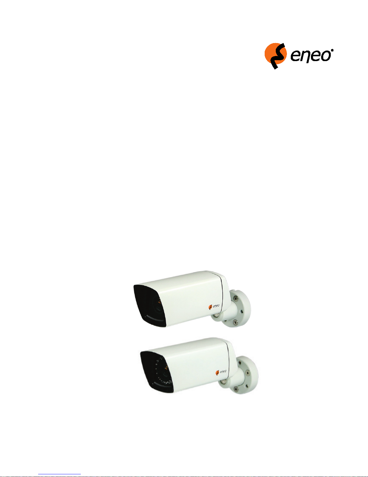
VKC-1327C/W3
VKC-1327C-IR/W3

1
Table of contents
1. Safety Instructions and Notes….......................................................................................................
2. General Descriptions............................................................................……………………………...
3
3
3. Supplied Items......................................................................................……………………………...
4. Part names…………………………….…...................................................…………………………...
5. Installation Instructions......................................................................................……………………...
6. Setup Menu ……………............................................................................…………………………...
7. Specifications ………………………………………………..................................................................
8. Drilling Plan ………………………………………………….…............................................................
9. Dimensional Drawings ……………………………………………......................................................
4
4
5
8
22
23
24
2
WARNING
Caution
To prevent electric shocks
and risk of fire hazards, do
NOT use other than specific
To prevent fire or shock hazard, do not expose the unit to rain or moisture.
The symbol is intended to alert the user to the presence of important
operating and maintenance(servicing) instructions in the literature
accompanying the unit.
The symbol is intended to alert the user to the presence of
uninsulated "dangerous voltage" within the product's enclosure that
may be of sufficient magnitude to constitute a risk of electric shock
to persons.
power source.
Warning(NTSC version) -- This equipment has been tested and found to comply with the limits for a Class
A digital device, pursuant to part 15 of the FCC Rules. These limits are designed to provide reasonable
protection against harmful interference when the equipment is operated in a commercial environment. This
equipment generates, uses, and can radiate radio frequency energy and, if not installed and used in
accordance with the instruction manual, may cause harmful interference to radio communications. Operation
of this equipment in a residential area is likely to cause harmful interference in which case the user will be
required to correct the interference at his own expense.
Caution -- Any changes or modifications in construction of this device which are not expressly approved by
the party responsible for compliance could void the user's authority to operate the equipment.
Mains power quality should be that of a typical commercial environment. If the user of the model requires
continued operation during power mains interruptions, it is recommended that the model be powered from
an uninterruptible power supply (UPS) or a battery.”
Notice -- The images used in manual are processed to help comprehension and may
differ from actual video of the camera.
WARNING
NEVER USE THIS CAMERA IN WATER.

3
1. Safety Instructions and Notes
• Please read this safety and operating instructions before putting the camera into operation.
• Keep the manual in a safe place for later reference.
• Pay attention to safety when laying the connection cable and observe that the cable is not subjected to
heavy loads, kinks or damage and no moisture can get in.
• Never open the device such as boards or lens.
The warranty becomes void if repairs are undertaken by unauthorized persons.
• Maintenance and repair have to be carried out only by authorized service centers.
• Use only a mild detergent to clean the housing.
• Keep clean the window surface from the dirt or dust, which may reflect the infrared light to the lens at night..
• The camera should never be operated beyond the technical specifications. This can lead to destruction.
• The camera should never be operated in the water.
2. General Descriptions
VKC-1327C/W3, VKC-1327C-IR/W3 which realizes 700TVL resolution and a crisp color reproduction with
High Density 1/3" Sony Super HAD CCD II (960H) and Effio-S image signal processor.
With Effio-S digital imaging system,
- Delivers the crystal clear images with 700TVL resolution that accurately capture every aspect of any
scene.
- Color signal processing provides the optimum balance between the luminance and chroma signals for
high color reproducibility even for the detail scene which contains very high spatial frequency.
- Provides D-WDR by Adaptive Tone Reproduction
- Incorporates 2D, 3D noise reduction signal processing
With ICR mechanism,
- Enhances its sensitivity about 10x at night time
- Can accepts the infrared light
Main features are;
· High Density 1/3" Sony Super HAD CCD II(960H)
· 700TV Line
· 0.0005Lux (F1.2@40IRE, DSSx4)
· D-WDR, ATR-EX(Adaptive Tone Reproduction)
· Sense-up ~ x64
· Noise reduction 2D NR & 3D NR
· DIS(Digital Image Stabilizer)
· E Zoom & Slow Shutter(Sens-up)
· Motion Detection & Privacy Mask
· HLC/BLC
· OSD menu, Multi-lingual Menu support
· UTC(Coaxitron Control Pelco D)
· 10x sensitivity enhancement by removing the optical filter
· Switches to B/W and able to accept IR light at night mode
· Enhanced sharpness compensation.
· Very low noise and superior picture quality
· Video sub-out port for easy installation & maintenance
4
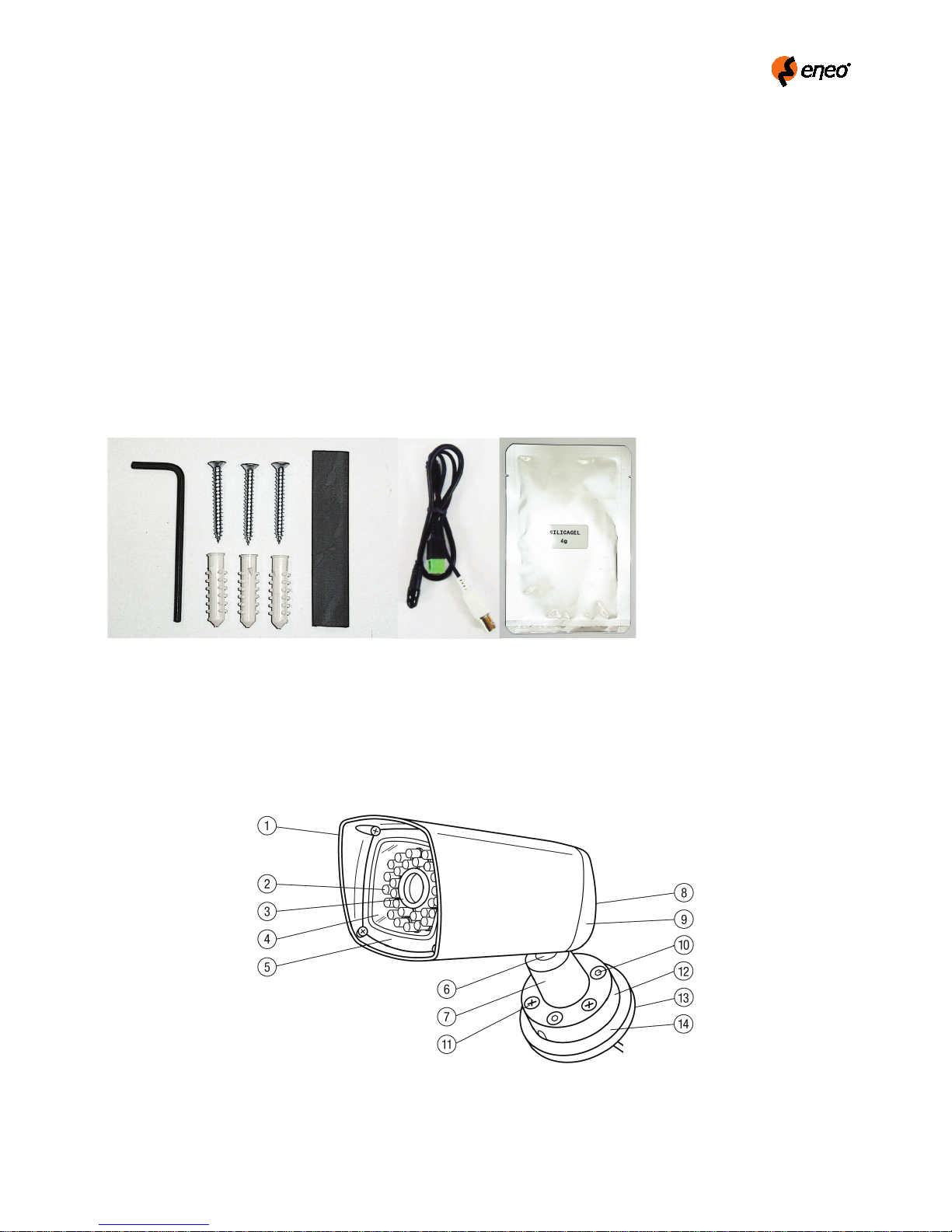
3. Supplied Items
⒜ ⒝
⒞
⒟ ⒠
⒡
• 1x Weather Proof Color Camera
• 1x Installation and Operating Instructions
• 1x ⒜3mm L-Hex wrench
• 3x ⒝Mounting screws
• 3x ⒞Anchors
• 1x ⒟Shrink tube
• 1x ⒠Easy Installation cable
• 1x ⒡Silica gel bag (4g) for the replacement when installing.
4. Part Names
4.1 External
5
①
②
③
④
⑤
⑥
⑦
⑧
⑨
⑩
⑪
⑫
⑬
⑭
ⓐ Lens hood
ⓑ
ⓒ
ⓓ
ⓔ
ⓕ
ⓖ
ⓗ
ⓘ
Housing body
17 IR LEDs (VKC-1327C-IR/W3 only).
Lens hood
Window
Front cover
Neck
Ball housing
Rear cover screws, 2x (not visible)
Rear cover
Neck fastening screws, 3x
Screws for installation kit, or (b) mounting screws, 3x
Mount base
Base plate assembly kit – (not visible) (optional)
Panel assembly kit (optional)
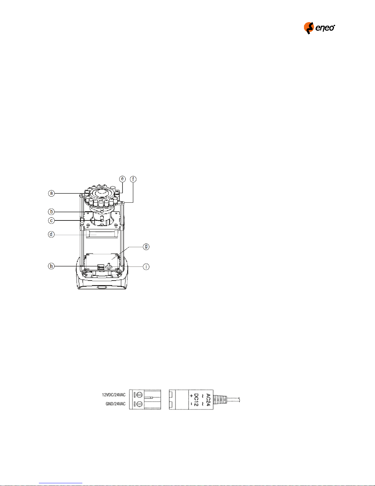
4.2 Internal
5. Installation Instructions
• Make sure the power is removed before installation.
5.1 Power Supply Connections
Camera can be operated with either 12Vdc or 24Vac.
Polarity free connection is acceptable but follow the indication if possible.
Focus adjustment knob
Zoom adjustment knob
Sensor board
Infrared LED
IR LED board ASS’Y
Power board
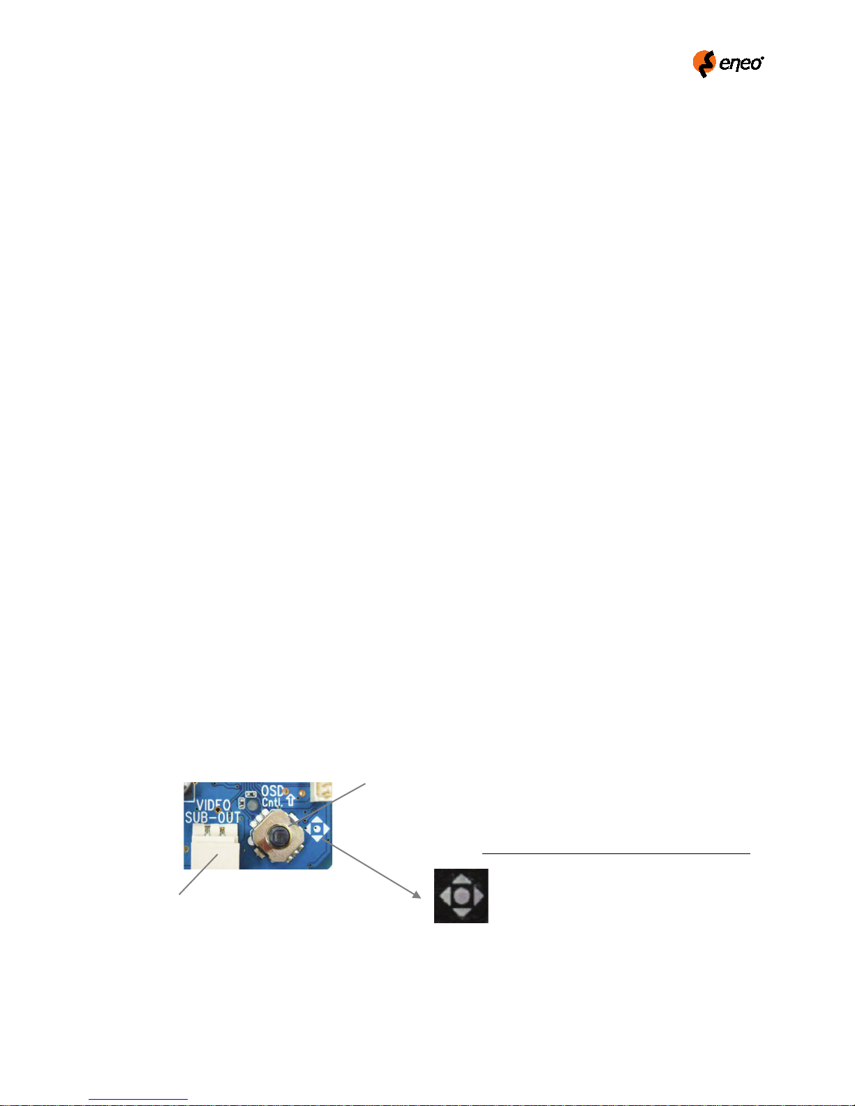
Video subout
OSD menu navigation (Joystick)
6
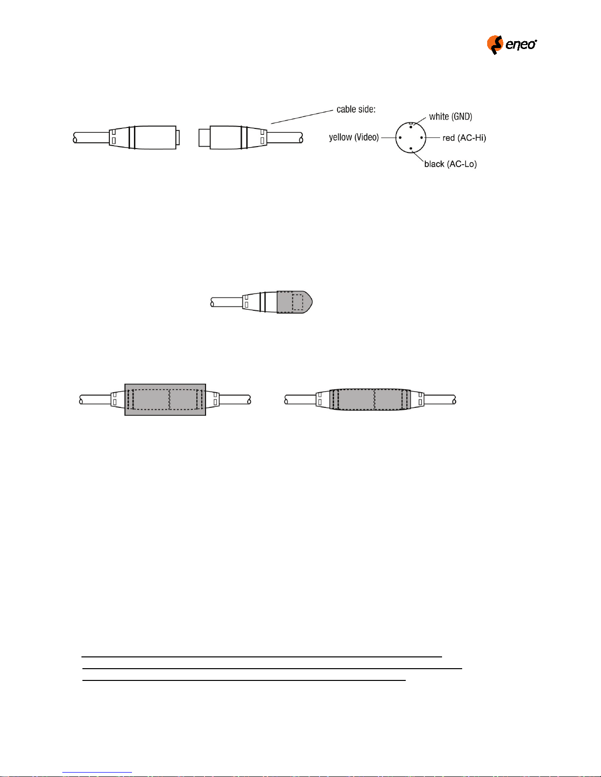
Easy Installation cable at the cable end
⑩
⑫
⑫
①
①
⑩
ⓒ
ⓑ
ⓘ
①
5.2 Installation Procedure
Connection (Easy installation) at the cable end
1. The cover cap serves to protect against dirt during the installation (e.g. when the cable is led through a wall).
2. The attached shrink tube serves to protect the connection.
To use this, cut off a suitable amount, push it over the connection and shrink it.
5.2.1 Installation on Wall
1) Loosen three
2) Secure the
Make sure that the cable is routed safely not to be damaged by the
3) Separate the
Make sure that inside of the
4) Set the camera direction roughly and fasten three
5) Apply the power to the camera.
6) Set the
After setting zoom and focus, secure the knobs
7) Adjust the setting parameters by using
8) Remove the power again.
9) Repeat step 1).
This step is a preparation for an easy assembling for step 10).
10) Replace the existing silica-gel bag with new one after setting camera control parameters.
11) Assemble the
When securing two ⑧ rear cover screws, do not complete one at a time and another next.
Both screws are recommended to be tightened evenly a little at a time in turn.
12) Trim the camera before the final secure and completely tighten three ⑩ neck fastening screws.
neck fastening screws a little (but not completely) so that camera body can move.
mount base with screws supplied to the wall or ceiling.
housing body by loosening two ⑧ rear cover screws and place it at a safe area.
housing body should not be contaminated by dust or liquid
neck fastening screws.
zoom and ⓑ focus
and ⓒ.
OSD Joystick.
housing body to the rear cover by tighten two rear ⑧ cover screws.
mount base (see gap).
7
ⓒ
ⓑ
ⓑ + ⓒ
6.1 In the menu
In the menu,
Joy stick
VIDEO
SYMBOL descriptions for joystick operation;
denotes the directions of
5.2.2 Installation on Ceiling
It is available for the upside down installation on the ceiling by re-arranging the camera module inside the
housing to be turned 180°.
The modification for upside down mounting must be carried out by authorized personnel.
5.2.3 NOTE – Silica gel bag
As it is not always possible to avoid a situation where a certain amount of moisture remains in the opened casing, we
recommend using the enclosed bag of silica gel in such cases. It must be ensured that the gel is used appropriately, i.e.
opening the protective film too soon can lead to the silica gel becoming saturated in a very short period of time, thereby
making it ineffective.
1. Before inserting the silica gel pack, please remove the aluminum protective sleeve around the pack, as the silica gel is
only effective without the aluminum protective sleeve.
2. Insert the pack between the back of the casing and the camera holder.
3. The silica gel retains the residual moisture that accumulated in the casing during assembly in a moist climate.
5.3 Setup of the Image Sector
• Pull off the camera housing.
• Power up the camera and connect a monitor.
• Loosen
• Loosen
• Tighten both locking screws
NOTE: For a precise adjustment of cameras installed outside it is recommended to place a ND (Neutral Density) filter in
Zoom adjustment knob and adjust the zoom setting.
Focus is adjustment knob and adjust the focus.
front of the lens while settings are done. This opens up the iris and allows a setting which is constant at changing
light conditions due to the narrower depth of field.
when adjustment is done. Close the housing.
6. SETUP Menu
Setup menu can be accessed and controlled by OSD control joy stick on the side of camera.
Five commands are available with the joy stick.
SUB-OUT
connector
use ▲,▼ to move menu, ◀,▶ to change the settings and press ● to select or enter.
-▲,▼,◀,▶
Joystick lever operation.
-● denotes Pressing straight down of
Joystick lever
 Loading...