

Eneo VKC-12120F2810IR Installation And Operation Manual

INSTALLATION AND OPERATION MANUAL
for
VKC-12120F2810IR

2
Table of contents
1. Safety Instructions and Notes….......................................................................................................
2. General Descriptions............................................................................……………………………...
3. Supplied Items......................................................................................……………………………...
4. Part names…………………………….…...................................................…………………………...
5. Installation Instructions......................................................................................……………………...
6. Setup Menu ……………............................................................................…………………………...
7. Specifications ………………………………………………..................................................................
8. Dimensional Drawings ……………………………………………............................................................
3
3
4
5
6
9
26
27
3
Caution
WARNING
To prevent fire or shock hazard, do not expose the unit to rain or moisture.
The symbol is intended to alert the user to the presence of important
operating and maintenance(servicing) instructions in the literature
accompanying the unit.
The symbol is intended to alert the user to the presence of
uninsulated "dangerous voltage" within the product's enclosure that
may be of sufficient magnitude to constitute a risk of electric shock
to persons.
To prevent electric shocks
and risk of fire hazards, do
NOT use other than specific
power source.
Warning(NTSC version) -- This equipment has been tested and found to comply with the limits for a Class
A digital device, pursuant to part 15 of the FCC Rules. These limits are designed to provide reasonable
protection against harmful interference when the equipment is operated in a commercial environment. This
equipment generates, uses, and can radiate radio frequency energy and, if not installed and used in
accordance with the instruction manual, may cause harmful interference to radio communications.
Operation of this equipment in a residential area is likely to cause harmful interference in which case the
user will be required to correct the interference at his own expense.
Caution -- Any changes or modifications in construction of this device which are not expressly approved by
the party responsible for compliance could void the user's authority to operate the equipment.
Mains power quality should be that of a typical commercial environment. If the user of the model requires
continued operation during power mains interruptions, it is recommended that the model be powered from
an uninterruptible power supply (UPS) or a battery.”
Notice -- The images used in manual are processed to help comprehension and may
differ from actual video of the camera.
WARNING
NEVER USE THIS CAMERA
1. IN WATER.
2. IN AREA WHERE HAS SHOCK OR VIBRATION WHICH RESULTS IN THE
PROBLEM FOR AUTO FOCUSING.

4
1. Safety Instructions and Notes
• Please read this safety and operating instructions before putting the camera into operation.
• Keep the manual in a safe place for later reference.
• Pay attention to safety when laying the connection cable and observe that the cable is not subjected to
heavy loads, kinks or damage and no moisture can get in.
• Never open the device such as boards or lens.
The warranty becomes void if repairs are undertaken by unauthorized persons.
• Maintenance and repair have to be carried out only by authorized service centers.
• Use only a mild detergent to clean the housing.
• Keep clean the window surface from the dirt or dust, which may reflect the infrared light to the lens at night..
• The camera should never be operated beyond the technical specifications. This can lead to destruction.
• The camera should never be operated in the water.
2. General Descriptions
WDR Camera which realizes 700TVL resolution and a crisp color reproduction with Sony 960H Double Scan
CCD and Effio-P image signal processor.
With Effio-P digital imaging system,
- Serves the well balanced video against the very highly contrasted scene with super WDR.
- Delivers the crystal clear images with 700TVL resolution that accurately capture every aspect of any scene.
- Color signal processing provides the optimum balance between the luminance and chroma signals for high
color reproducibility even for the detail scene which contains very high spatial frequency.
- Incorporates 2-D & 3-D noise reduction signal processing
With ICR mechanism,
- Enhances its sensitivity about 10x at night time
- Can accepts the infrared light
With 24VAC/12VDC dual power design,
- Offers the flexibility of installation
- Ensures the reliability
Main features are;
• High Density 1/3" Sony Double Scan CCD(960H)
• WDR(Wide Dynamic Range)
• Resolution 700 Horizontal Lines
• ATR-EX(Adaptive Tone Reproduction-EX)
• Digital Image Stabilizer
• E-Zoom
• Sens-up upto 64x by Digital Slow Shutter
• HLC/BLC
• 2-D & 3-D noise reduction
• Motion Detection
• Privacy Mask function
5
• UTC(Coaxitron Control Pelco D)
① ② ③ ④ ⑤
• OSD menu and camera ID
• Switches to B/W and able to accept the infrared spectrum at night mode
• Very low noise and superior picture quality
• Sensitivity of 0.0001Lux (F1.2@40IRE, DSSx4)
• True Day/night by Automatically removable IR Cut Filter(ICR)
• Automatic White Balance (ATW)
• External Zoom & Focus Adjustment
• One touch 3 Axis Bracket
• Supply voltage: 24Vac/12Vdc Dual voltage
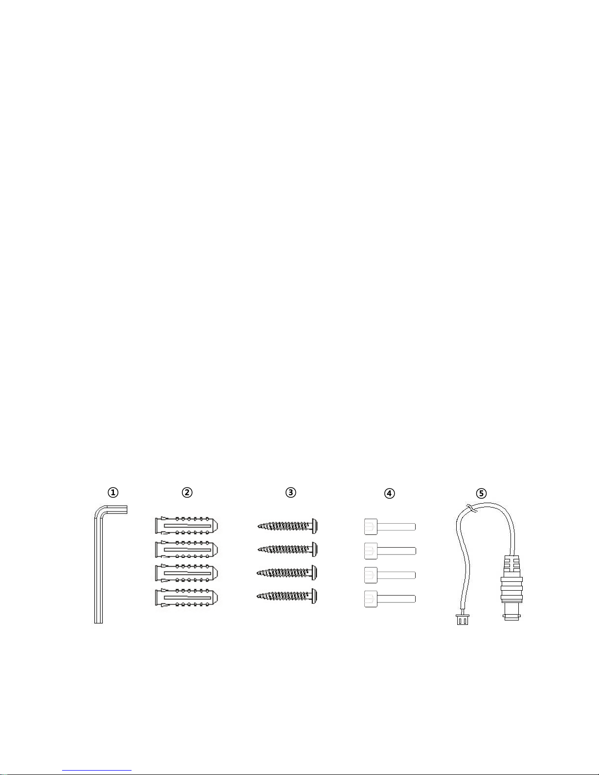
3. Supplied Items
• 1x WDR Weatherproof Bullet Camera
• 1x Installation and Operating Instructions
• 1x Mounting template
• 1x Easy Bracket
• 1x ①3mm Hex L-wrench
• 4x ②anchors
• 4x ③Wall fixing screws
• 4x ④M4 Wrench Bolts
• 1x ⑤Video Sub-out cable
6
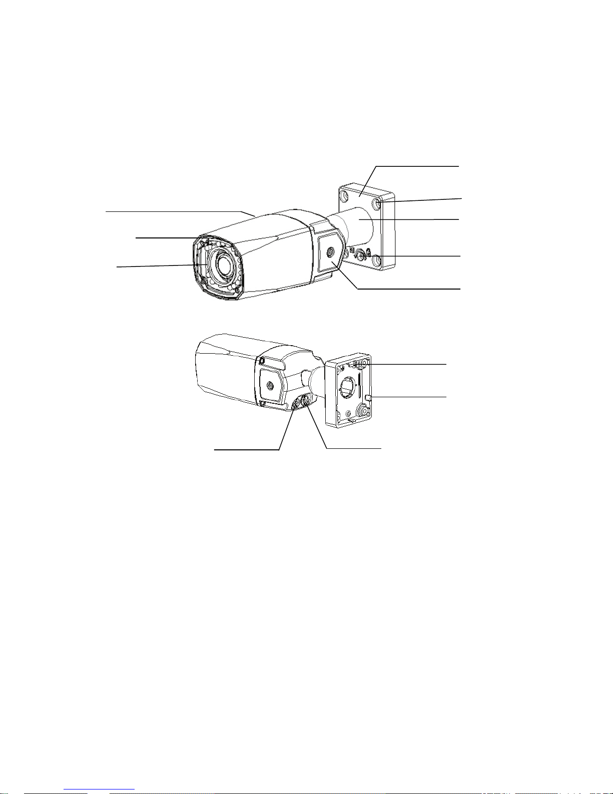
4. Part Names
ⓐ Front cover
ⓒ
ⓓ
ⓔ Foot mount Hole(x4)
ⓕ
ⓖ
ⓗ
ⓘ Hook for Easy Bracket
ⓙ
ⓚ
ⓛ
4.1 Front / Rear View
ⓓ
ⓐ
ⓒ
ⓑ
ⓚ
ⓛ
ⓔ
ⓕ
ⓖ
ⓗ
ⓘ
ⓙ
ⓑ IR LED
Window
Bracket Foot
Arm assembly
Bracket Lock
OSD cover
Cable Exits
Focus adjustment
Zoom adjustment
7
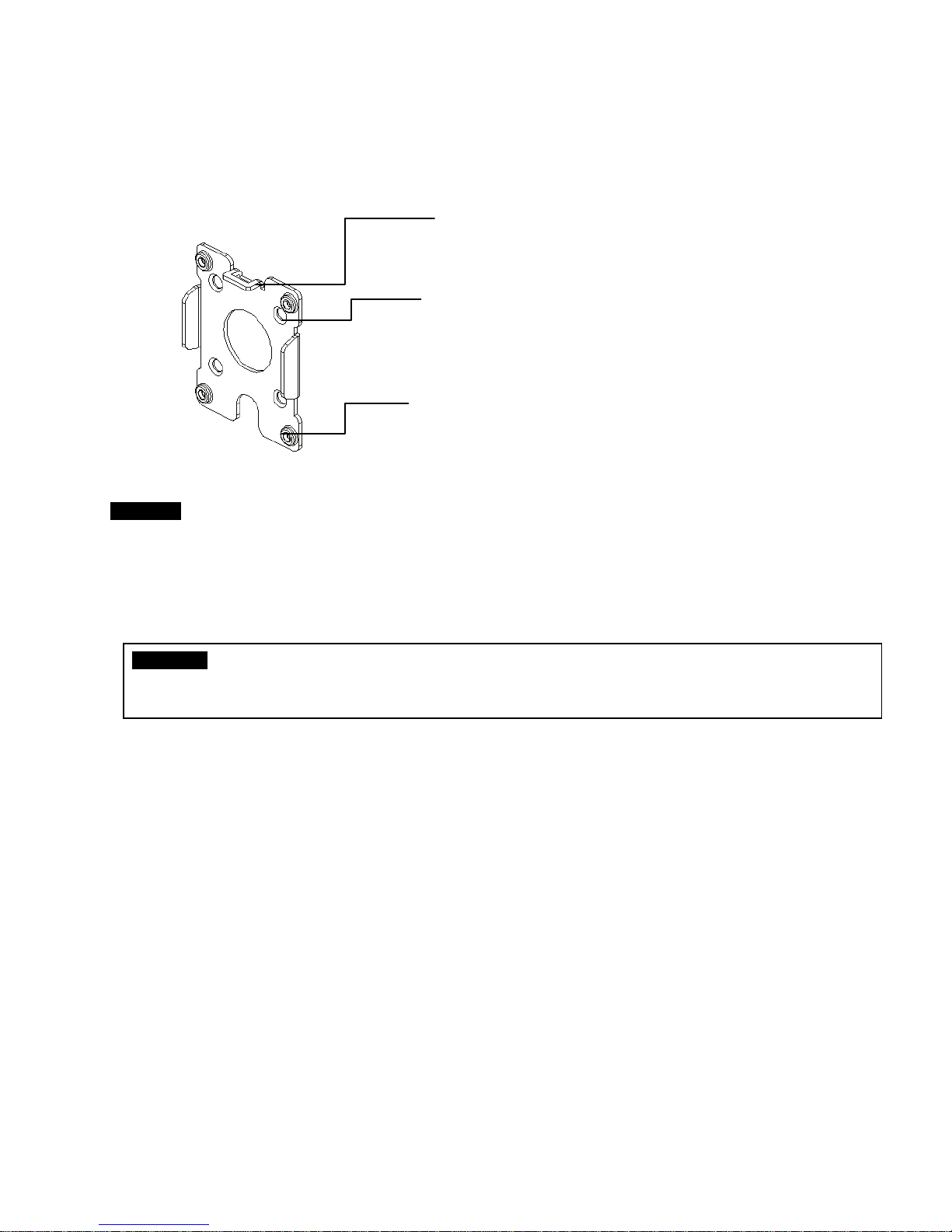
4.2 Easy Bracket
CAUTION - Easy Bracket can not be installed on the ceiling.
When it is installed on the wall, ⓜPeg for Easy bracket Hook must be placed upwardly.
5. Installation Instructions
WARNING NEVER USE THIS CAMERA
1) in WATER.
2) in area where has SHOCK or VIBRATION which results in the problems for Auto Focus operation.
• Make sure the power is removed before the installation.
• Follow the order for applying power.
First, connect the low voltage (AC24V or DC12V), then plug the AC adapter to AC outlets to avoid an
improper reset from power jitter and a damage from the surge voltage when no load.
ⓜ
ⓜ Peg for Easy Bracket Hook(ⓘ)
ⓝ
ⓝ Wall Mount hole(x4)
ⓞ Bracket foot fixing hole(x4)
ⓞ
8
CAUTION - Easy Bracket can not
be placed upwardly.
5.1. Mounting the camera on wall
5.1.1 Without using an Easy Bracket.
1) Drill the holes on wall or ceiling using a supplied template.
2) Insert the ②anchors to the drilled holes
3) Match ⓔFoot mount Hole(x4) to the drilled position
4) Fix the bracket by using ③Wall fixing screws
5.1.2 With using an Easy Bracket.
1) Drill the holes on wall using a supplied template.
2) Insert the ②anchors to the drilled holes
3) Match the EASY BRACKET to the drilled position
4) Fix the EASY BRACKET by using ③Wall fixing screws
5) Connect hook(ⓘ) to peg(ⓜ)
6) Fix ⓓBracket Foot to EASY BRACKET by using
④wrench bolts through ⓔFoot mount Hole(x4)
be installed on the ceiling.
When it is installed on the ceiling,
ⓜPeg for Easy bracket Hook must
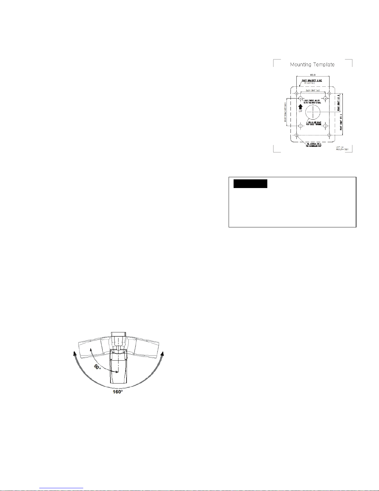
5.3. Limit of pan and tilt
1. Pan limit
Pan is limited to +/- 80°.

9
2. Tilt limit
Installation on Wall
Installation on Ceiling
Tilt is limited to 0°(2°) min ~ 90° max. for wall(ceiling) installation respectively with reference to the
ceiling when the inclination of camera module is 0°, that is, the image is aligned horizontally.
3. Inclination limit (Horizontal image alignment)
Inclination limited to +/-90° max.
 Loading...