

Page 1
Page 2

Page 3
Network Video Recorder
i
WARNING
RISK OF ELECTRIC SHOCK
DO NOT OPEN
WARNING: TO REDUCE THE RISK OF ELECTRIC SHOCK,
DO NOT REMOVE COVER (OR BACK).
NO USER-SERVICEABLE PARTS INSIDE.
REFER SERVICING TO QUALIFIED
SERVICE PERSONNEL.
The lightning flash with arrowhead symbol, within an equilateral triangle, is intended to alert
the user to the presence of uninsulated "dangerous voltage" within the product's enclosure
that may be of sufficient magnitude to constitute a risk of electric shock.
The exclamation point within an equilateral triangle is intended to alert the user to the presence
of important operating and maintenance (servicing) instructions in the literature accompanying
the appliance.
COMPLIANCE NOTICE OF FCC:
THIS EQUIPMENT HAS BEEN TESTED AND FOUND TO COMPLY WITH THE LIMITS FOR A CLASS A DIGITAL
DEVICE, PURSUANT TO PART 15 OF THE FCC RULES. THESE LIMITS ARE DESIGNED TO PROVIDE
REASONABLE PROTECTION AGAINST HARMFUL INTERFERENCE WHEN THE EQUIPMENT IS OPERATED IN
A COMMERCIAL ENVIRONMENT. THIS EQUIPMENT GENERATES, USES, AND CAN RADIATE RADIO
FREQUENCY ENERGY AND IF NOT INSTALLED AND USED IN ACCORDANCE WITH THE INSTRUCTION
MANUAL, MAY CAUSE HARMFUL INTERFERENCE TO RADIO COMMUNICATIONS. OPERATION OF THIS
EQUIPMENT IN A RESIDENTIAL AREA IS LIKELY TO CAUSE HARMFUL INTERFERENCE, IN WHICH CASE
USERS WILL BE REQUIRED TO CORRECT THE INTERFERENCE AT THEIR OWN EXPENSE.
WARNING: CHANGES OR MODIFICATIONS NOT EXPRESSLY APPROVED BY THE PARTY RESPONSIBLE
FOR COMPLIANCE COULD VOID THE USER’S AUTHORITY TO OPERATE THE EQUIPMENT.
THIS CLASS OF DIGITAL APPARATUS MEETS ALL REQUIREMENTS OF THE CANADIAN INTERFERENCECAUSING EQUIPMENT REGULATIONS.
The information in this manual is believed to be accurate as of the date of publication. We are not responsible for any
problems resulting from the use thereof. The information contained herein is subject to change without notice. Revisions
or new editions to this publication may be issued to incorporate such changes.
The software included in this product contains some Open Sources. You may obtain the complete corresponding
source code from us. See the Open Source Guide on the software CD (OpenSourceGuide\OpenSourceGuide.pdf)
or as a printed document included along with the User's Manual.
Page 4

Quick Reference Guide
ii
Important Safeguards
1. Read Instructions
All the safety and operating instructions should be read before the
appliance is operated.
2. Keep Instructions
The safety and operating instructions should be kept for future
reference.
3. Cleaning
Unplug this equipment from the wall outlet before cleaning it. Do
not use liquid aerosol cleaners. Use a damp soft cloth for cleaning.
4. Attachments
Never add any attachments and/or equipment without the approval
of the manufacturer as such additions may result in the risk of fire,
electric shock or other personal injury.
5. Water and/or Moisture
Do not use this equipment near water or in contact with water.
6. Accessories
Do not place this equipment on an unstable cart, stand or table. The
equipment may fall, causing serious injury to a child or adult, and
serious damage to the equipment. Wall or shelf mounting should
follow the manufacturer's instructions, and should use a mounting
kit approved by the manufacturer.
This equipment and cart combination should be moved with care.
Quick stops, excessive force, and uneven surfaces may cause the
equipment and cart combination to overturn.
7. Ventilation
Slots and openings in the cabinet and the back or bottom are provided
for ventilation, and to ensure reliable operation of the equipment and
to protect it from overheating. These openings must not be blocked
or covered. Do not block these openings or allow them to be blocked
by placing the equipment on a bed, sofa, rug, or bookcase. Ensure that
there is adequate ventilation and that the manufacturer’s instructions
have been adhered to.
8. Power Sources
This equipment should be operated only from the type of power source
indicated on the marking label. If you are not sure of the type of
power, please consult your equipment dealer or local power company.
9. Power Cords
Operator or installer must remove power and other connections before
handling the equipment.
10. Lightning
For added protection for this equipment during a lightning storm,
or when it is left unattended and unused for long periods of time,
unplug it from the wall outlet and disconnect the antenna or cable
system. This will prevent damage to the equipment due to lightning
and power-line surges.
11. Overloading
Do not overload wall outlets and extension cords as this can result
in the risk of fire or electric shock.
12. Objects and Liquids
Never push objects of any kind through openings of this equipment
as they may touch dangerous voltage points or short out parts that
could result in a fire or electric shock. Never spill liquid of any kind
on the equipment.
13. Servicing
Do not attempt to service this equipment yourself. Refer all servicing
to qualified service personnel.
14. Damage requiring Service
Unplug this equipment from the wall outlet and refer servicing to
qualified service personnel under the following conditions:
A. When the power-supply cord or the plug has been damaged.
B. If liquid is spilled, or objects have fallen into the equipment.
C. If the equipment has been exposed to rain or water.
D. If the equipment does not operate normally by following the
operating instructions, adjust only those controls that are covered
by the operating instructions as an improper adjustment of other
controls may result in damage and will often require extensive work
by a qualified technician to restore the equipment to its normal
operation.
E. If the equipment has been dropped, or the cabinet damaged.
F. When the equipment exhibits a distinct change in performance —
this indicates a need for service.
15. Replacement Parts
When replacement parts are required, be sure the service technician
has used replacement parts specified by the manufacturer or that have
the same characteristics as the original part. Unauthorized substitutions
may result in fire, electric shock or other hazards.
16. Safety Check
Upon completion of any service or repairs to this equipment, ask
the service technician to perform safety checks to determine that the
equipment is in proper operating condition.
17. Field Installation
This installation should be made by a qualified service person and
should conform to all local codes.
18. Telnet Communication Cable
Caution: To reduce the risk of fire, use only No. 26 AWG or larger
telecommunication line cord.
19. Danger of explosion if battery is incorrectly replaced. Replace
only with same or equivalent type recommended by manufacturer.
Discard used batteries according to the manufacturer’s instruction.
WEEE (Waste Electrical & Electronic Equipment)
Correct Disposal of This Product
(Applicable in the European Union and other European countries with separate collection systems)
This marking shown on the product or its literature, indicates that it should not be disposed with other household wastes at the
end of its working life. To prevent possible harm to the environment or human health from uncontrolled waste disposal, please
separate this from other types of wastes and recycle it responsibly to promote the sustainable reuse of material resources.
Household users should contact either the retailer where they purchased this product, or their local government office, for
details of where and how they can take this item for environmentally safe recycling.
Business users should contact their supplier and check the terms and conditions of the purchase contract. This product should
not be mixed with other commercial wastes for disposal.
Page 5

Network Video Recorder
iii
Table of Contents
Chapter 1 — Introduction ............................................................................................ 1
1.1 Features ............................................................................................................ 1
1.2 System Diagram ................................................................................................ 2
1.3 Rear Panel ........................................................................................................ 2
Factory Reset .................................................................................................... 3
1.4 Front Panel ........................................................................................................ 3
1.5 Tuning On/Off the System ................................................................................. 3
Chapter 2 — Installation .............................................................................................. 4
Package Contents ............................................................................................. 4
2.1 INIT Program ..................................................................................................... 4
2.2 iNEX Program ................................................................................................... 4
System Requirements ....................................................................................... 4
Installation ......................................................................................................... 5
Chapter 3 — Getting Started ....................................................................................... 7
3.1 Connecting ........................................................................................................ 7
System Setup .................................................................................................... 8
3.2 Registering Devices ........................................................................................ 11
3.3 Live Video Monitoring ...................................................................................... 15
3.4 Recording ........................................................................................................ 15
Allocating Cameras ......................................................................................... 16
Setting up Recording Schedule ...................................................................... 17
3.5 Playing Recorded Video .................................................................................. 18
Chapter 4 — Federation Service ............................................................................... 19
4.1 Installation ....................................................................................................... 19
System Requirements ..................................................................................... 19
Installation ....................................................................................................... 19
4.2 Getting Started ................................................................................................ 20
Running Service .............................................................................................. 20
Log In .............................................................................................................. 20
System Setup .................................................................................................. 21
Registering Service ......................................................................................... 22
Live Video Monitoring ..................................................................................... 23
Playing Recorded Video ................................................................................. 24
Chapter 5 — Specification ......................................................................................... 25
Page 6

Quick Reference Guide
iv
Page 7

Network Video Recorder
1
Chapter 1 — Introduction
This manual describes installation and operation of Network Video Recorder (NVR), which is designed
to be used with network cameras, network video transmitters and DVRs.
1.1 Features
This network video recorder provides monitoring of video from network video transmitters, network cameras
and DVRs, recording of monitoring video (DVR excluded) and playback of video recorded in the NVR
system or DVR.
Remote monitoring of live images
Remote monitoring of live images in a WAN environment through a streaming service by up to two users
(the number of channels that can be streamed equals the number of channels that can be recorded)
Management and monitoring of multiple NVR systems (max. 256) using Federation Service
Up to 10 simultaneous connections to the NVR system
Remote software upgrades and system setup (supported only for devices which provide the functions)
Display of system log information (supported only for devices which use the iNEX protocol)
Map monitoring of live images
Centralized system operation and management and event handling
Management of multiple NVR systems (max. 256) using Federation Service
Decompression algorithm for H.264, MPEG-4 and M-JPEG
Enhanced security using the SSL function
Two-way audio communication
Enhanced security by setting up different authorities for each user group
Intuitive GUI
The following are supported only for network cameras and network video transmitters:
− Recording of video and playback of the recorded video
− Instant Recording of monitored images
− Audio recording
− Stable recording using proprietary video database file system
The following are supported only for DVRs:
− Playback of video recorded in DVRs
− Remote control of panic recording
Number of devices that can be registered and channels that can be recorded and streamed:
− Registration: Maximum of 128 devices (16 for DVRs)
− Recording (not supported for DVRs): Maximum of 4 (4-channel model) /8 (8-channel model) /16
(16-channel model) channels
− Streaming (not supported for DVRs): The number of channels that can be streamed equals the number
of channels that can be recorded.
NOTES:
See the User’s Manual which is included on the CD for details about configuring and operating the NVR.
If the device is a four-channel network video transmitter which uses the iNEX protocol, all four cameras
are counted even if some of the four cameras are disabled, and four channels per network video transmitter
are deducted from the number of channels available for recording and streaming.
The iNEX Federation software is provided to allow you to build better surveillance systems. Refer to
Chapter 4 — Federation Service (p. 21) for details.
Page 8
Quick Reference Guide
2
NOTES:
This manual covers the 4-, 8- and 16-channel network video recorders. For simplicity, the illustrations and
descriptions in this manual refer to the 16-channel model.
This product includes software developed by the OpenSSL Project for use in the OpenSSL Toolkit
(http://www.openssl.org/).
The software included in this product contains some Open Sources. You may obtain the complete
corresponding source code from us. See the Open Source Guide on the software CD (OpenSourceGuide\
OpenSourceGuide.pdf) or as a printed document included along with the User's Manual.
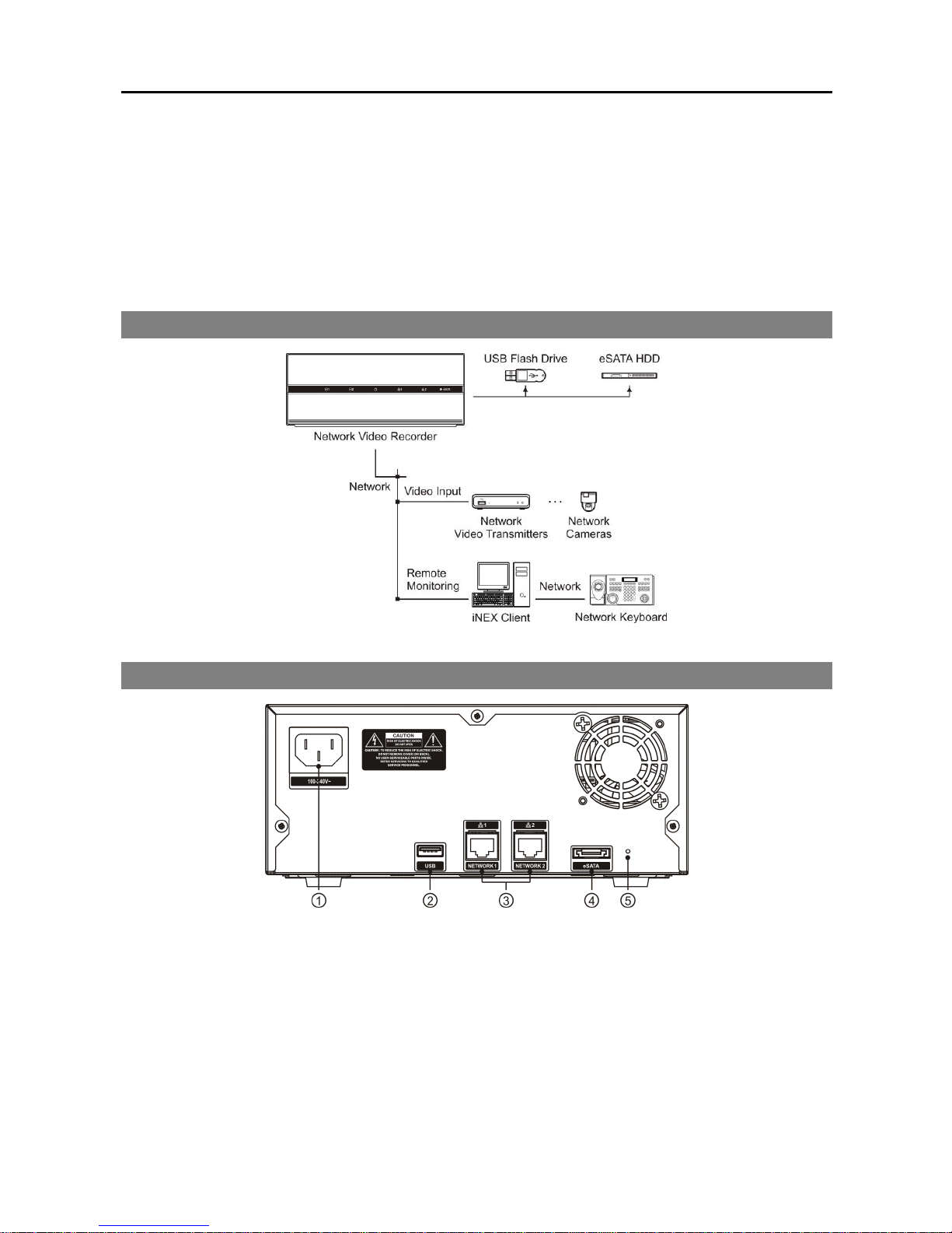
1.2 System Diagram
1.3 Rear Panel
① Power In: Connect a power cord.
② USB Port: Connect a USB flash drive to upgrade the software. Disconnect power from the NVR and
connect a USB flash drive containing the upgrade package file (.rui and autorun.txt) to the NVR. The
autorun.txt file should contain only the upgrade file name and its extension (.rui) (ex. Install=160-1601.rui).
Connect power to the NVR, and the software will be upgraded automatically. When upgrading is complete,
a beep sounds. You can upgrade the software remotely by running the INIT program or iNEX program.
Refer to 3.1 Connecting (p. 9) for details about remote software upgrade using the iNEX program.
Refer to the INIT User’s Manual for details about remote software upgrade using the INIT program.
③ Network (RJ-45): Connect a Cat5/Cat5e cable with an RJ-45 jack. Refer to 3.1 Connecting (p. 9)
for details about network setting.
Page 9
Network Video Recorder
3
④ eSATA: Connect the external eSATA hard disk drive cable to connect external storage devices.
⑤ Factory Reset Switch: Use to return all settings except device related settings to the original factory
settings. See below for details.
NOTES:
Do NOT connect or disconnect eSATA devices while the NVR power is on. The NVR must be powered
down to connect or disconnect eSATA devices. Power up eSATA devices so they are ready for operation
before powering up the NVR. Power down eSATA devices after powering down the NVR and then
disconnect eSATA devices.
If the eSATA device is shut down while the NVR is operating, the NVR system might not operate normally.
Factory Reset
This switch will only be used on the rare occasions that you want to return all the settings to the original
factory settings.
CAUTION: When performing a Factory Reset, you will lose any settings except device related
settings you have saved.
Cut off the power from the NVR. → Poke a straightened paperclip into the factory reset switch hole. →
Turn on the power while holding the reset switch → Release the switch after the system turns on and a beep
sounds. → The NVR resets to factory defaults and restarts after completing the factory reset.
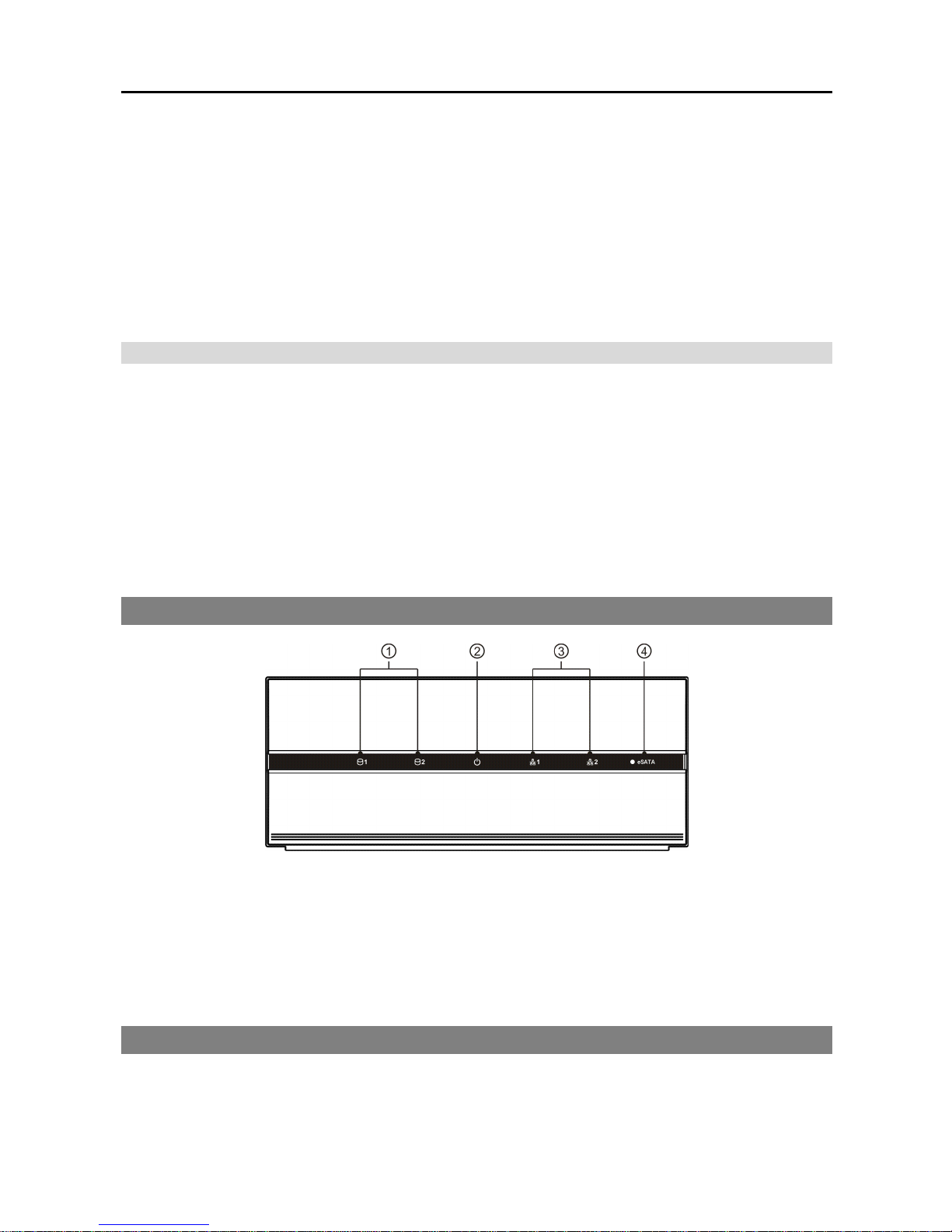
1.4 Front Panel
① HDD LED: A green LED flickers when the system accesses to the hard disk drive. A red LED is lit when
any error occurs in the hard disk drive. If the system does not boot up normally due to a hard disk drive
error, red LEDs are lit and a beep sounds.
② Power LED: Is lit when the unit is turned on.
③ Network LED: Is lit when the NVR is connected to a network via Ethernet.
④ eSATA LED: Flickers when the system accesses to the eSATA hard disk drive.
1.5 Tuning On/Off the System
Connecting the power cord to the NVR turns on the unit.
Page 10

Quick Reference Guide
4
Chapter 2 — Installation
You can connect the NVR system remotely only via network connection. This requires installing the
following programs in your PC.
INIT Program: Allows you to set up network information of the NVR system for remote connection.
iNEX Program: Allows you to set up the NVR system, to monitor video of the NVR system and to play
back video recorded in the NVR system.
Package Contents
Installation CD (iNEX/INIT Software, Network Video Recorder/INIT User’s Manual)
Quick Reference Guide (This document)
2.1 INIT Program
The INIT program does not require installation procedures, and double clicking the executable file runs the
INIT program. Refer to the INIT User’s Manual for details about the INIT program.
NOTE: The INIT program provides the following functions only:
Lookup, Setup – IP Address Setup, Management – Upgrade.
1. Check that the NVR system is operating.
2. Insert the installation CD and run the INIT program by double clicking the INIT.exe file in the INIT
folder.
3. Select the NVR system to connect.
4. Click the Setup icon in the Main screen, select IP Address Setup and enter the login information
(The default user ID is admin and default password is 12345678).
5. Enter the network information when the IP Address Setup screen appears. You can check the network
information including the administration port number of the NVR system by selecting the NVR system,
clicking the right mouse button and selecting Properties on the Main screen.
2.2 iNEX Program
System Requirements
Recommended Requirements
Operating System: Microsoft® Windows® XP x86 (32 Bit)/Vista (Home Basic, Business, Ultimate,
Enterprise), Microsoft® Windows® 7 (Home Premium, Professional, Ultimate)
CPU: Intel Core II Quad 8200 2.33 GHz or faster
RAM: 2GB or more
Page 11

Network Video Recorder
5
VGA: ATI RadeonTM HD 3650 or NVIDIA GeForce 8400GS (ATI recommended) (1024x768, 24bpp
or higher)
Hard Disk Drive: 350 MB or more free space
LAN: Gigabit Ethernet or faster
Minimum System Requirements
Operating System: Microsoft® Windows® XP Home SP 3
CPU: Intel Pentium IV 3.0 GHz or faster
RAM: 1.5 GB or more
VGA: ATI RadeonTM HD 2400 or NVIDIA GeForce FX5500 (ATI recommended) (1024x768, 24bpp
or higher)
Hard Disk Drive: 350 MB or more free space
LAN: 10/100 Mbps Ethernet or faster
Installation
NOTES:
The Client program should be installed on a PC for monitoring, recording and playback of video. If necessary,
install the federation service for management and monitoring of multiple NVR systems. Refer to Chapter 4
— Federation Service (p. 21) for details about the federation service.
In the Windows Start menu, go to Control Panel. Double click the Power Options to open the Management
Properties dialog box. Under the Power Schemes tab, set both Turn off monitor and Turn off hard disks
to Never.
CAUTION: If an older version of iNEX software is installed on your computer, a screen
appears asking you to upgrade the software. In this case, you are required to upgrade the
software according to the instructions in the screen.
1. Insert the software CD in the PC.
2. Run the ClientSetup.exe file of the software CD.
NOTE: The User Account Control window might appear when using the Microsoft® Windows® Vista or later
operating system. Click Allow and install the software following the instructions.
3. Select the language in which to run the program and then click OK.
NOTES:
To properly display the selected language, your PC’s operating system should be set to support the
selected language.
To change the iNEX program’s language after the software has been installed, select Language Selector
in the iNEX → Utility folder of the Start menu before running the iNEX program.
Page 12
Quick Reference Guide
6
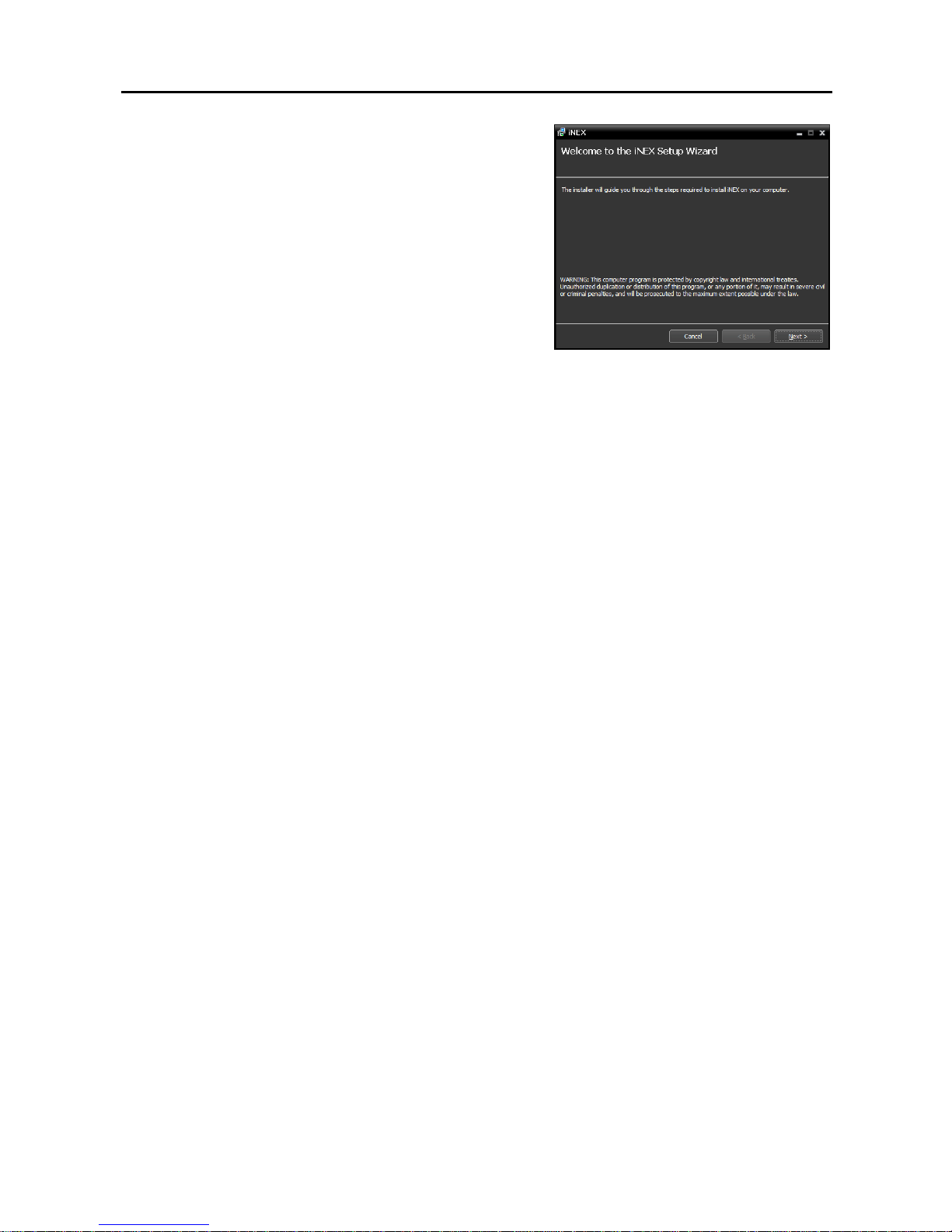
4. When the following screen appears, click Next.
Refer to the User’s Manual which is included on the CD for the setup instructions in detail.
Page 13
Network Video Recorder
7
Chapter 3 — Getting Started
NOTE: In this manual, the “server or server system” refers to a PC on which a iNEX service is running, the
“client system” refers to a PC on which the Client program is running and the “network video device” refers
to a network video transmitter or network camera.
3.1 Connecting
When it is complete to set up network information of the NVR system using the INIT program and to install
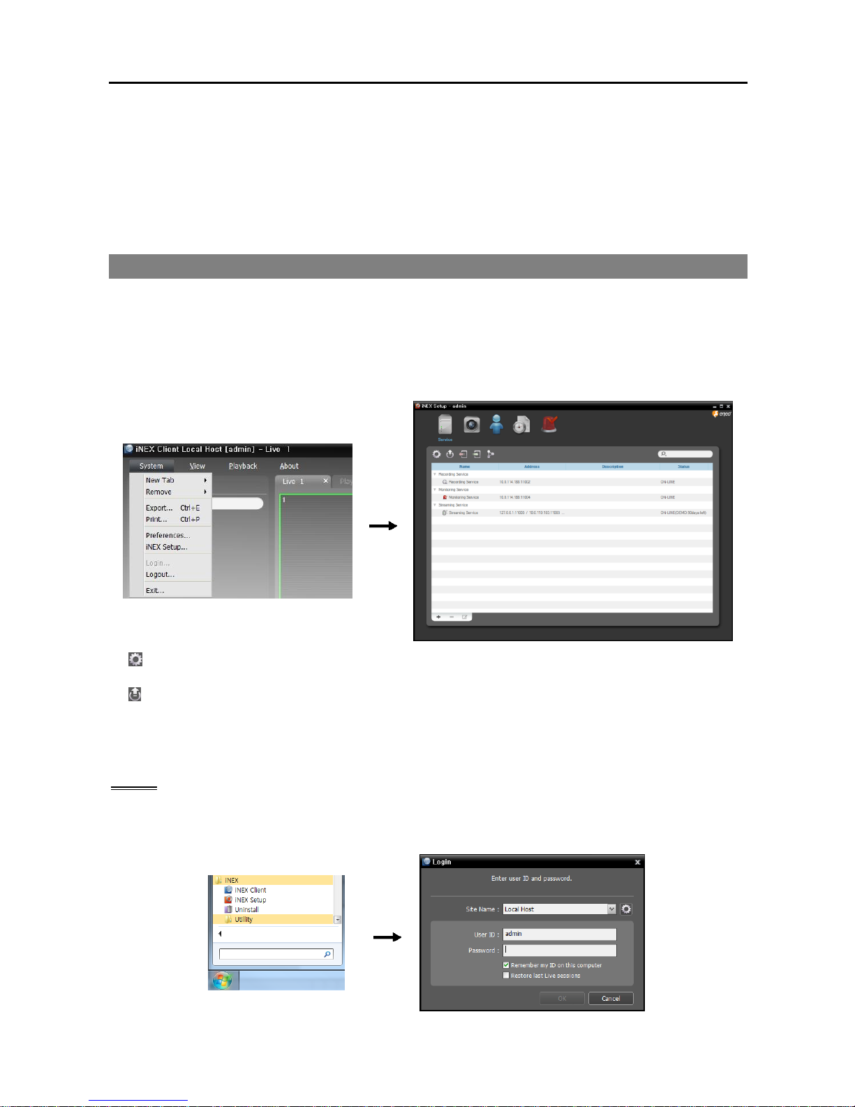
the iNEX program, connect to the NVR system remotely as follows:
Log in the NVR system in the iNEX Client system → Click iNEX Setup in the System Menu and run
the iNEX Setup program. Refer to following explanation for details about logging in the NVR system.
(System Setup): Clicking the button allows you to set up the system. Refer to System Setup (p. 10)
for details.
(Upgrade): Clicking the button and selecting a upgrade file upgrades the software of NVR system.
You can also upgrade the software by using the INIT program (Run the INIT program → Click the
Management menu → Select Upgrade). This is supported for the users belonging to the default user
group (Administrators).
Log In
Go to the Start Menu in the Client system → Click iNEX → Run the iNEX Client program and enter login
information.
Page 14
Quick Reference Guide
8
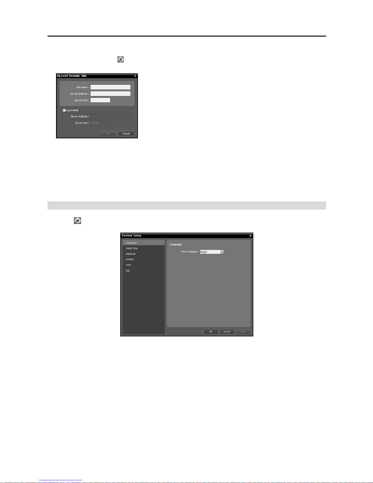
Site Name: Select the NVR system to connect to from the list. If you connect to the NVR system for
the first time, click the button at the right, select Add or Modify and enter network information of
the NVR system to connect
− Site Name, Service Address, Service Port: Designate the name
of the NVR system and enter the IP address and port number of the
NVR system (default: 11001). If the NVR system uses the DVRNS
function, check Use DVRNS and enter the IP address (domain
name) and port number of the DVRNS server that the NVR system
is registered. It allows you to enter the name instead of the IP address
of the NVR system when entering Service Address. The name you
enter should be the same as the name registered on the DVRNS server.
Refer to System Setup, DVRNS (p. 12) for details about the
DVRNS function.
User ID, Password: Enter your user ID and password. The default user ID is admin and default password
is 12345678. You can change the user ID and password in the User menu.
Remember my ID on this computer: Check the box if you want to save your ID for logging on.
Restore last Live sessions: Check the box if you want to restore the previous live monitoring sessions
in the current Live panels of the Client program (supported only for the Client program).
System Setup
Click the (System Setup) button to display the system setup screen.
Page 15
Network Video Recorder
9
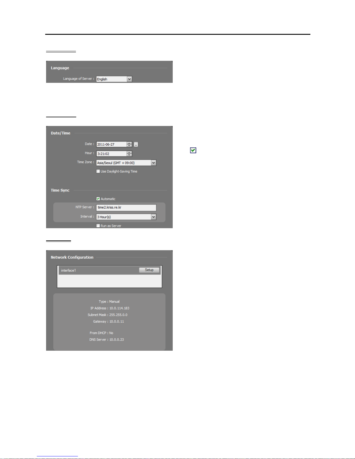
Language
Select the language in which to run the NVR system.
It is not necessary to match it to the iNEX program’s
language. It is recommended to match it to the
language of text such as camera titles of devices to be
registered on the NVR system. Otherwise, text may
not be displayed properly on the iNEX program.
Date/Time
Date, Time, Time Zone: Displays the date, time
and time zone of the NVR system.
Time Sync
− Automatic Sync: Automatically synchronizes
the time with a time server. Enter the IP address
or the domain name of the time server and set the
time interval for synchronization.
− Run as Server: Check the box to run the NVR
system as a time server.
Network
A list of network cards installed in the NVR system
is displayed. Selecting a network card displays the
network information of the selected network card and
clicking the Setup button allows you to change the
network settings. Ask your network provider for
details about the network connection type and
connection information for the NVR system or the
IP address of the DNS server.
IP Address Type: Select the type of NVR system’s
network configuration.
− Set Manually: Select when the system is using
a static IP address for network connection, and
set up LAN parameters manually.
− DHCP: Select when the system is networked via DHCP (Dynamic Host Configuration Protocol). Click
the Apply button, and network information is automatically assigned to the device. If the NVR system
is configured for a DHCP network, it is best to use the DVRNS function because the NVR system’s
IP address might change frequently. See DVRNS below for details about the DVRNS function.
DNS Server: Enter the IP address of the DNS server. If you set up the DNS server, the domain name
of the server can be used instead of the IP address during the DVRNS or time server setup. Ask your
Internet service provider for the IP Address of the DNS Server. When the NVR system is networked
via DHCP, selecting From DHCP automatically assigns the IP address of the DNS server. The assigned
IP address is displayed the next time it is connected.
Page 16
Quick Reference Guide
10
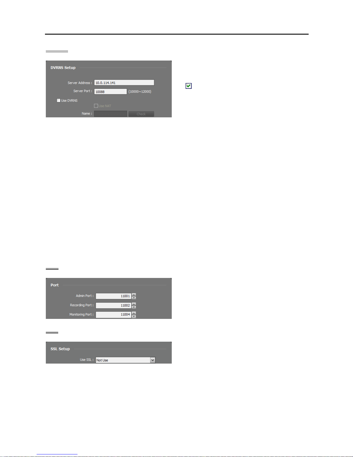
DVRNS
Server Address, Server Port: Enter the IP address
(domain name) and port number of the DVRNS
server to register the NVR system.
Use DVRNS: Allows you to enter the name
instead of the IP address of the NVR system by
using the DVRNS function when connecting to
the NVR system.
− Use NAT: Check the box when the NVR system uses a NAT (Network Address Translation) device
for network connection.
− Name: Enter the NVR system name to be registered on the DVRNS server. Check whether or not the
name is available by clicking the Check button.
NOTES:
The DVRNS (DVR Name Service) function allows the NVR system to use dynamic IP addresses for remote
connection. When using this function, you can access the NVR system remotely by using the NVR system
name instead of its IP address. For the DVRNS function to work properly, the NVR system should be
registered on the DVRNS server.
When LAN settings are changed, set up the DVRNS settings after saving your LAN changes by clicking
the OK button.
You will need to get the IP address or domain name of the DVRNS server from your network
administrator. You can use the domain name instead of IP address if you set up the DNS server during
the IP Address setup.
When using a NAT (Network Address Translation) device, refer to the NAT manufacturer’s instructions
for the proper network settings.
The NVR system name you entered in the Name field should be checked by clicking the Check button,
otherwise the DVRNS changes will not be saved. When entering no name or a name already registered
on the DVRNS server, an error message displays.
Port
It allows you to change the port numbers of the
administration, recording and monitoring services
that are running in the NVR system.
SSL
Use SSL: Allows you to enhance the security of
data transferred between services of the iNEX
program by using the SSL (Secure Sockets Layer)
protocol. Using the SSL function might cause
congestion in the NVR system depending on the
security level. Log in the iNEX program again
after you change the setting. When the setting is
changed, all services that are currently connected
to the administration service reconnect, and the
iNEX Setup and iNEX Client programs are logged
out.
Page 17
Network Video Recorder
11
3.2 Registering Devices
You must register devices on the NVR system and add the devices to a device group in order to perform
any operation.
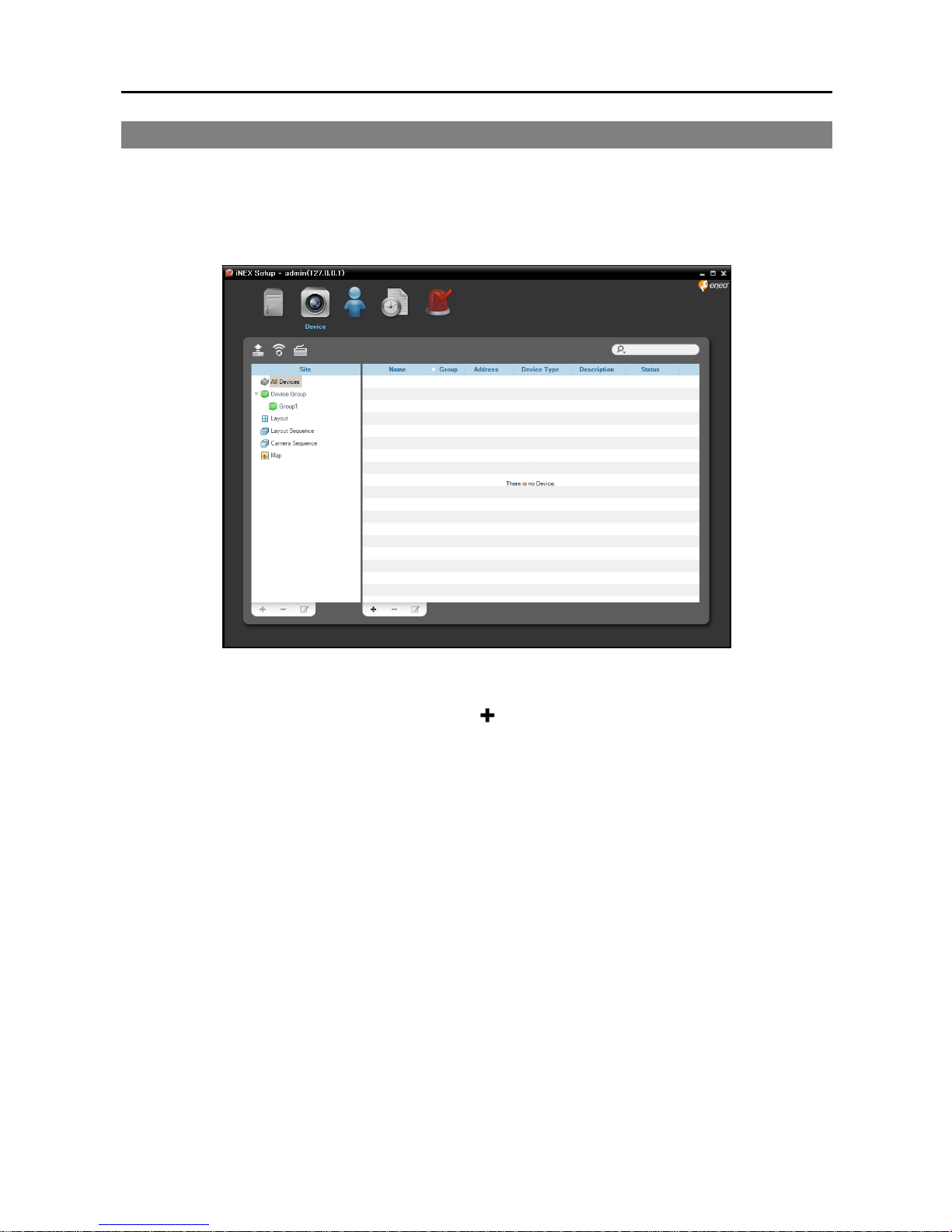
Run the Setup program. Refer to 3.1 Connecting (p. 9) for details about running the Setup program.
1. Select the Device menu.
2. Click All Devices in the Site panel, and then the button at the bottom of the Site List panel. The
Device Scan window appears.
Page 18
Quick Reference Guide
12
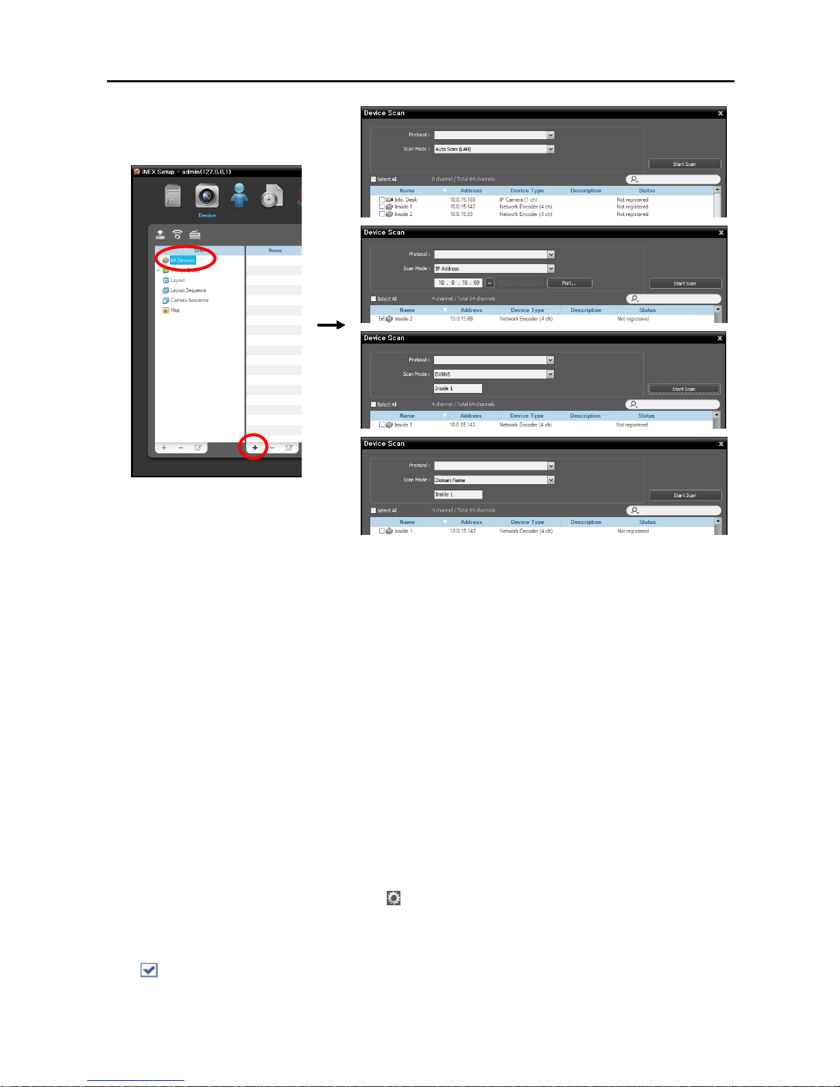
Protocol: Select the protocol or manufacturer of the device to scan. Event related functions may not
be supported depending on the protocol that the device uses (supported for the iNEX protocol and
some versions of the ONVIFTM Conformance and Axis protocol), and some other functions may not
be supported depending on the settings of the device.
Scan Mode: Select the scan mode. Clicking the Start Scan button displays the results in the list. If
the IP address range of the device is different from that of the NVR system, the iNEX program considers
the IP address invalid. In this case, you must change the device’s IP address to register the device.
− Auto Scan (LAN): Lists devices in a LAN environment (supported only for the network video devices).
If the device uses the ONVIFTM Conformance protocol, this function is supported only when you
have checked the Disable WS-Discovery Windows Service (fdPHost, FDResPub) box during
the software installation in Microsoft® Windows® Vista or later operating systems. Also, if the device
uses the ONVIFTM Conformance protocol, it is recommended that the device not be networked via
DHCP (Dynamic Host Configuration Protocol). If the device is networked via DHCP, connection
to the device may not be made properly depending on changes in the external network environment.
− IP Address: Allows you to enter the IP address of a device. You can search more than one device
at a time by entering a range of IP addresses. It is recommended that the device not be networked
via DHCP (Dynamic Host Configuration Protocol). If the device is networked via DHCP, connection
to the device may not be made properly depending on changes in the external network environment.
− DVRNS: Allows you to enter the device name registered on a DVRNS server if the device uses the
DVR Name Service (DVRNS) function. Ensure the DVRNS server information on which the device
is registered is correct (Service menu → (System Setup) button). If the DVRNS server information
is not correct, the device will not be found.
− Domain Name: Allows you to enter the device's domain name registered on a DNS server if the
device uses the Domain Name Service.
: Select the devices to register by checking the box beside each device name in the list. Selecting
the Select All box selects all devices in the list.
Page 19
Network Video Recorder
13
NOTES:
Depending on the model, the device may not be supported even though the iNEX program supports the
device's protocol. Ask your dealer or distributor about supported models.
If the device uses the ONVIFTM Conformance protocol, you can select either the manufacturer (or iNEX
protocol) or the ONVIFTM Conformance protocol. However, it is possible that one or both of them are not
supported depending on the device model. Ask your dealer or distributor for details. Refer to the device
User’s Manual about enabling the ONVIFTM Conformance protocol in the device, as procedures may differ
for each model.
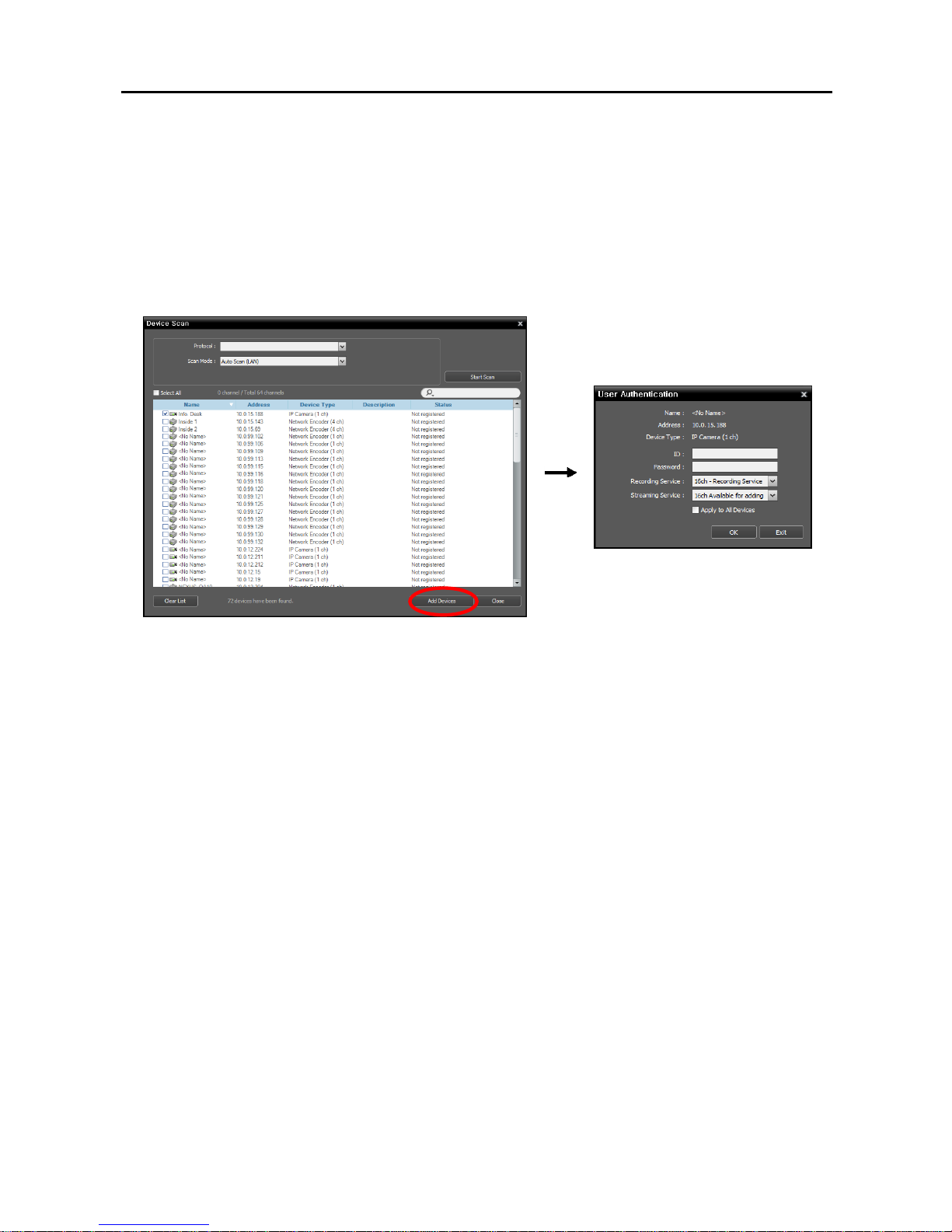
3. Click the Add Devices button at the bottom.
Name, Address, Device Type: Displays the name, IP address and type of the selected device. The
name will be updated automatically depending on the settings of the device.
ID, Password: Enter the user ID and password which you set in the device in order to connect to that
device remotely. The connection to the device is allowed only to the users under the Administrator
group of the device, and recording is allowed only to the admin user under the Administrator group
of the device.
Recording Service: Select a recording service (supported only for the network video devices). The
device is registered on the recording service and the NVR system performs recording according to a
recording schedule. The channel number of the recording service indicates the maximum number of
cameras that can be registered, and the name indicates the name of a recording service, which was
set during the Service menu setup. When selecting the Do not record option, the iNEX program
treats the device during the Schedule setup as though it was not registered and does not perform any
of the scheduled activities associated with the device. If you delete the device from the recording
service after some recording has been done, you cannot search or play back the previously recorded
video though you register the device again. You can check the list of devices registered on the recording
service on a Device Setup tab while setting up the recording service in the Service menu.
Streaming Service: Select whether or not to use the streaming service for monitoring video from
the device. Streaming service allows remote monitoring of live images in a WAN environment (up
to two users). The number of channels that can be streamed equals the number of channels that can
be recorded.
Apply to All Devices: Select to apply the same user ID and password to all selected devices if you
selected more than one device and the selected devises have the same user ID and password.
Page 20
Quick Reference Guide
14
NOTES:
If the device is a DVR, it might be necessary to enter the DVR port numbers depending on the specifications
and version of the DVR.
When registering a four-channel network video transmitter which uses the iNEX protocol, all four cameras
are automatically registered even if some of the four cameras are disabled.
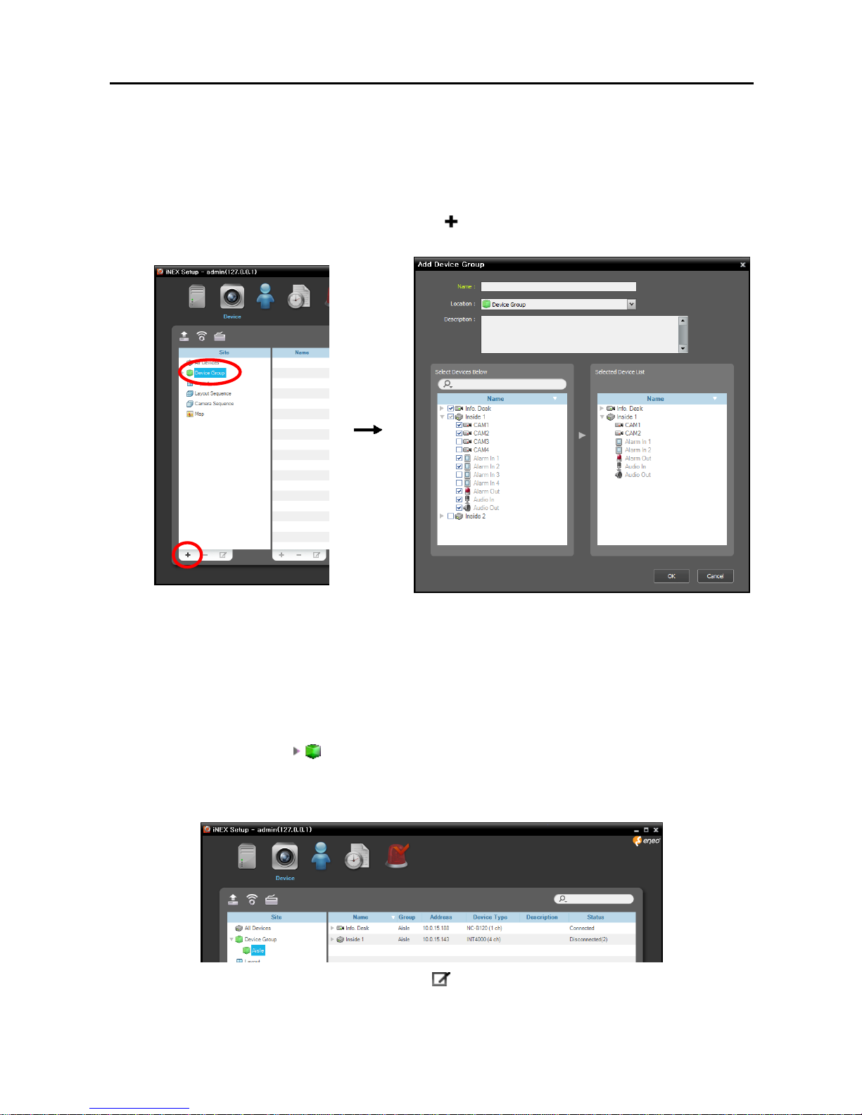
4. Click Device Group in the Site panel, and then the button at the bottom of the Site panel. The Add
Device Group window appears.
Name: Enter the device group name.
Location: Select an upper group to which the device group will belong.
Select Devices Below, Selected Device List: Check the box beside cameras in the left panel, and
the selected cameras are added to the right panel.
Clicking the OK button completes the device group registration.
5. Check that the device was added to the device group correctly. Click Device Group in the Site panel
and then the arrow button ( ) beside Device Group. Clicking the registered group displays the list
of devices added to the device group and connection status in the Site List panel. If the connection was not
made properly, the network disconnection log is displayed (only for devices registered on the recording
service).
Selecting the registered device group, and then the button at the bottom of the Site List panel displays
the Edit Device Group window and allows you to edit the selected device group.
Page 21
Network Video Recorder
15
3.3 Live Video Monitoring
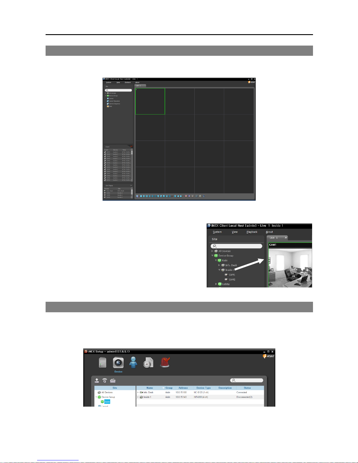
Go to the Start Menu → Click iNEX → Run the iNEX Client program and enter login information.
1. Check that the devices were added to a device group in the Site list.
2. Click the Live tab on the tab panel → Select a site to connect
to from the Site list, and drag and drop it on the Live screen.
Live video from the selected site is displayed on the screen.
3.4 Recording
Run the Setup program. Refer to 3.1 Connecting (p. 9) for details about running the Setup program.
Check that the devices were added to a device group in the Device menu.
Page 22
Quick Reference Guide
16
Allocating Cameras
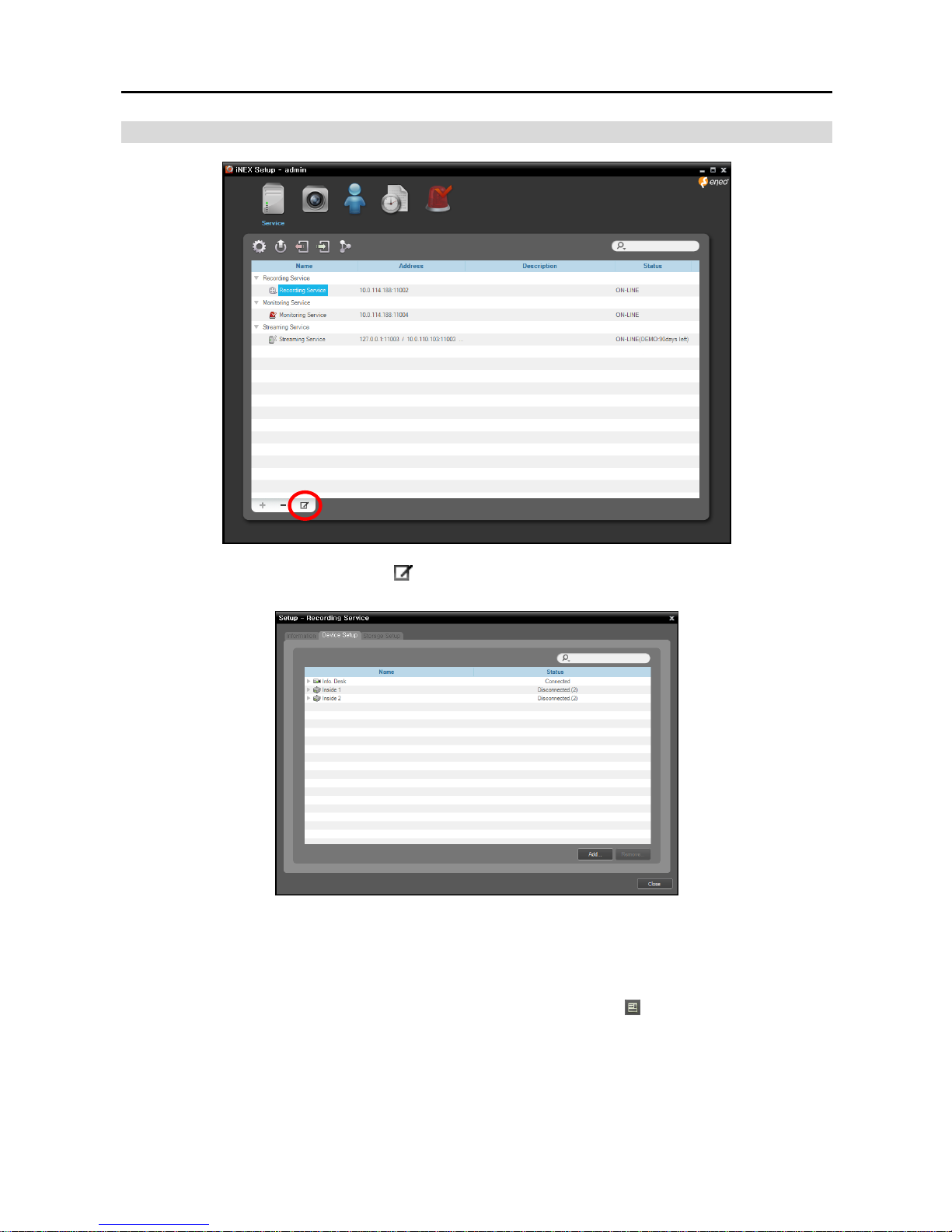
1. Select a recording service and click the button at the bottom. The Setup – Recording Service window
appears. Select the Device Setup tab.
The list of cameras registered on the current recording service is displayed. Clicking the Add button at the
bottom allows you to register additional cameras on the current recording service.
NOTE: If you remove a device for which some recording has been done and register the device again, the
NVR system considers the device as a new device. In this case, you can search or play back video recorded
before the device was removed as follows: go to the Play panel → click the (Additional Menu) button →
select Removed Devices.
Page 23
Network Video Recorder
17
Setting up Recording Schedule
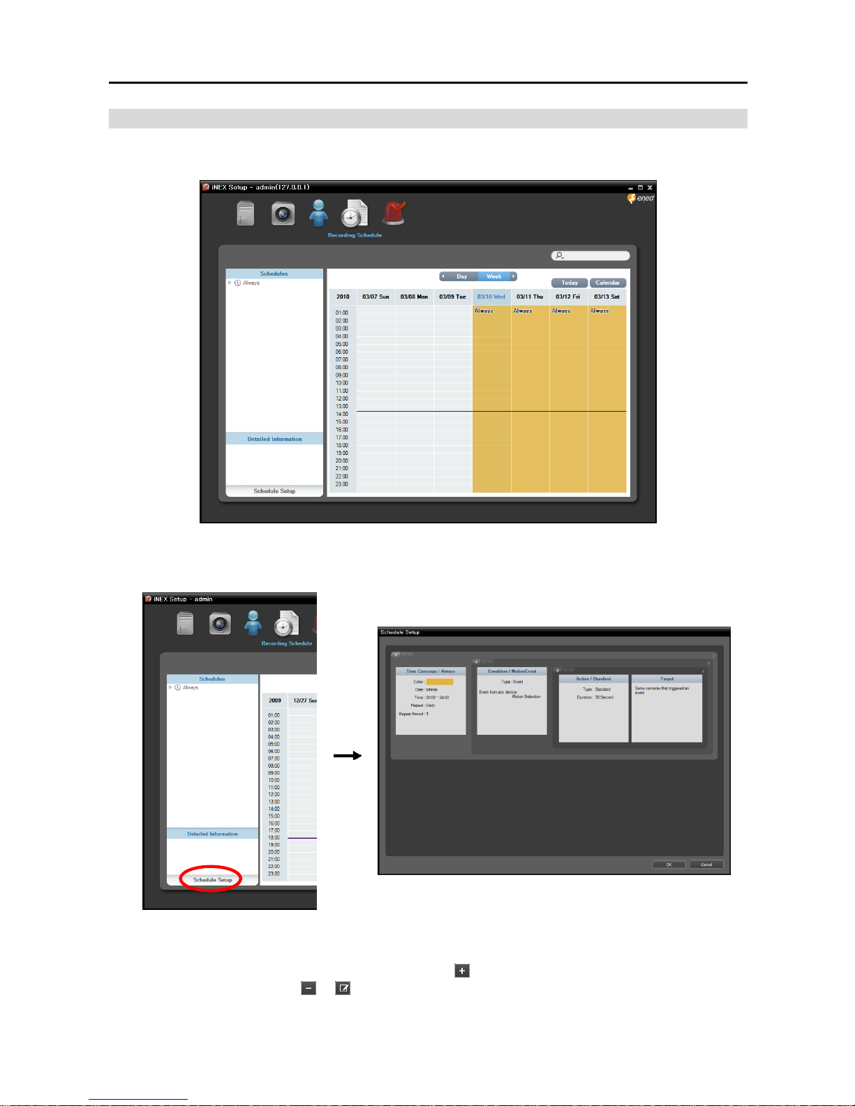
Select the Recording Schedule menu and set up the recording schedule following the procedures below.
1. Click the Schedule Setup button at the bottom. The Schedule Setup window appears, and schedule
windows are displayed with the current settings for each Preset.
2. Double click anywhere in the empty space of each schedule window, and the Preset setup window appears.
3. Select a desired Preset from the Preset list, or click the button to add a new Preset. Selecting a Preset
from the list and clicking the or button deletes the selected Preset or allows you to edit the selected
Preset settings. Clicking the OK button applies the settings.
Page 24
Quick Reference Guide
18
3.5 Playing Recorded Video
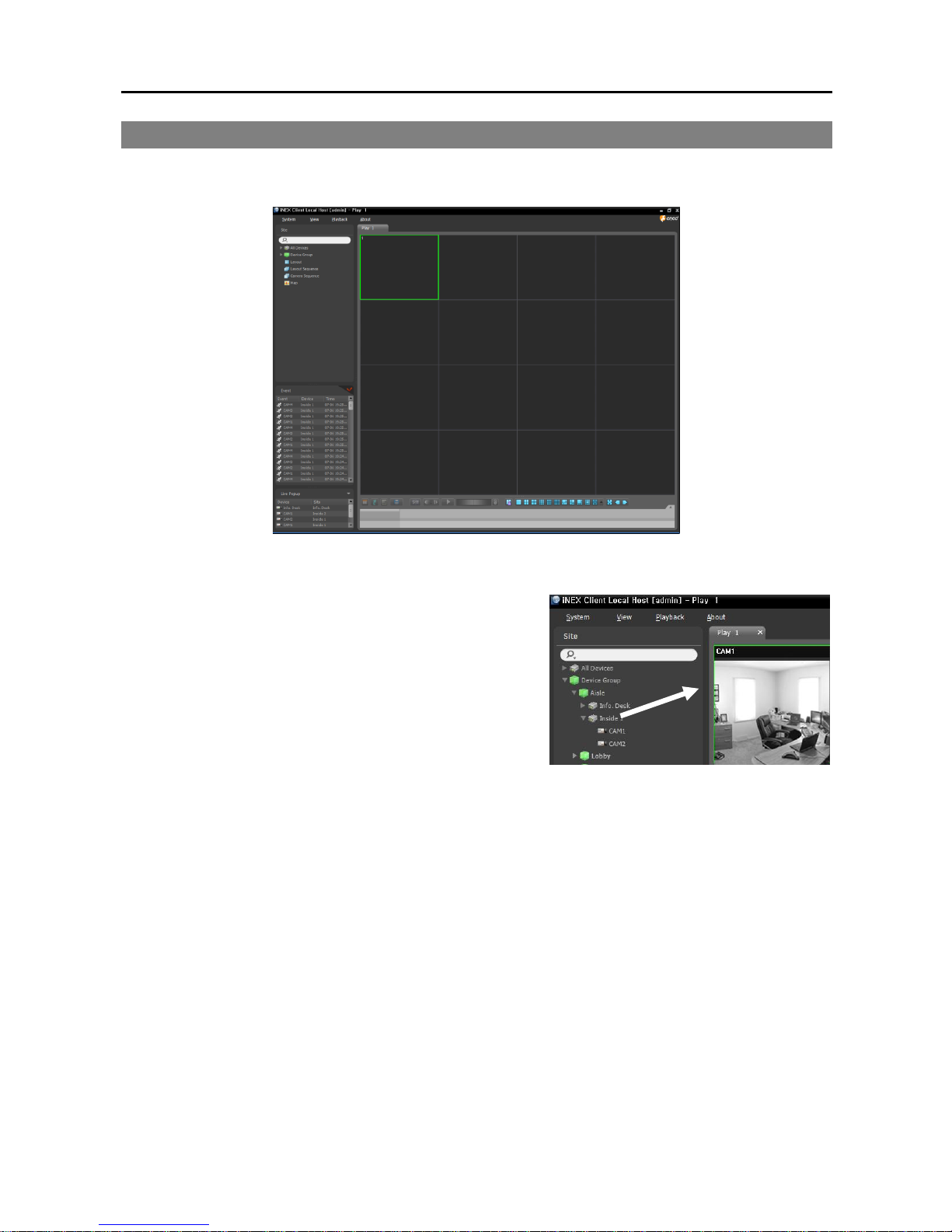
Go to the Start Menu → Click iNEX → Run the iNEX Client program and enter login information.
1. Check that the devices were added to a device group in the Site list.
2. Click the Play or DVR Search tab on the tab panel → Select
a site to connect to from the Site list, and then drag and drop
it on the Play or DVR Search screen. Recorded video from
the selected site is displayed on the screen. You can search
and play back recorded video by using the panel toolbar and
timetable at the bottom of the Play or DVR Search panel.
Page 25

Network Video Recorder
19
Chapter 4 — Federation Service
The federation service allows you to monitor live video from devices registered on the NVR system and
to play back video recorded in the NVR systems that are registered on the federation service.
4.1 Installation
System Requirements
Operating System: Microsoft® Windows® XP x86 (32 Bit)/Vista (Home Standard, Business, Ultimate,
Enterprise), Microsoft® Windows® 7 (Home Premium, Professional, Ultimate), Microsoft® Windows®
Server 2003/2008
CPU: Intel Core II Quad 8200 2.33 GHz/Intel Xeon 3.0 GHz or faster
RAM: 2GB or more
VGA: ATI RadeonTM HD 2400 or NVIDIA GeForce FX5500 (ATI recommended) (1024x768, 24bpp
or higher)
Hard Disk Drive: 5 GB or more free space
LAN: Gigabit Ethernet or faster
Installation
NOTE: In the Windows Start menu, go to Control Panel. Double click the Power Options to open the
Management Properties dialog box. Under the Power Schemes tab, set both Turn off monitor and Turn off
hard disks to Never.
CAUTION: If an older version of iNEX software is installed on your computer, a screen
appears asking you to upgrade the software. In this case, you are required to upgrade the
software according to the instructions in the screen.
1. Insert the software CD.
2. Run the FederationSetup.exe file of the software CD.
NOTE: The User Account Control window might appear when using the Microsoft® Windows® Vista or later
operating system. Click Allow and install the software following the instructions.
3. Select the language in which to run the program and then click OK.
NOTES:
To properly display the selected language, your PC’s operating system should be set to support the selected
language.
To change the iNEX program’s language after the software has been installed, select Language Selector in
the iNEX → Utility folder of the Start menu before running the iNEX program.
Page 26
Quick Reference Guide
20
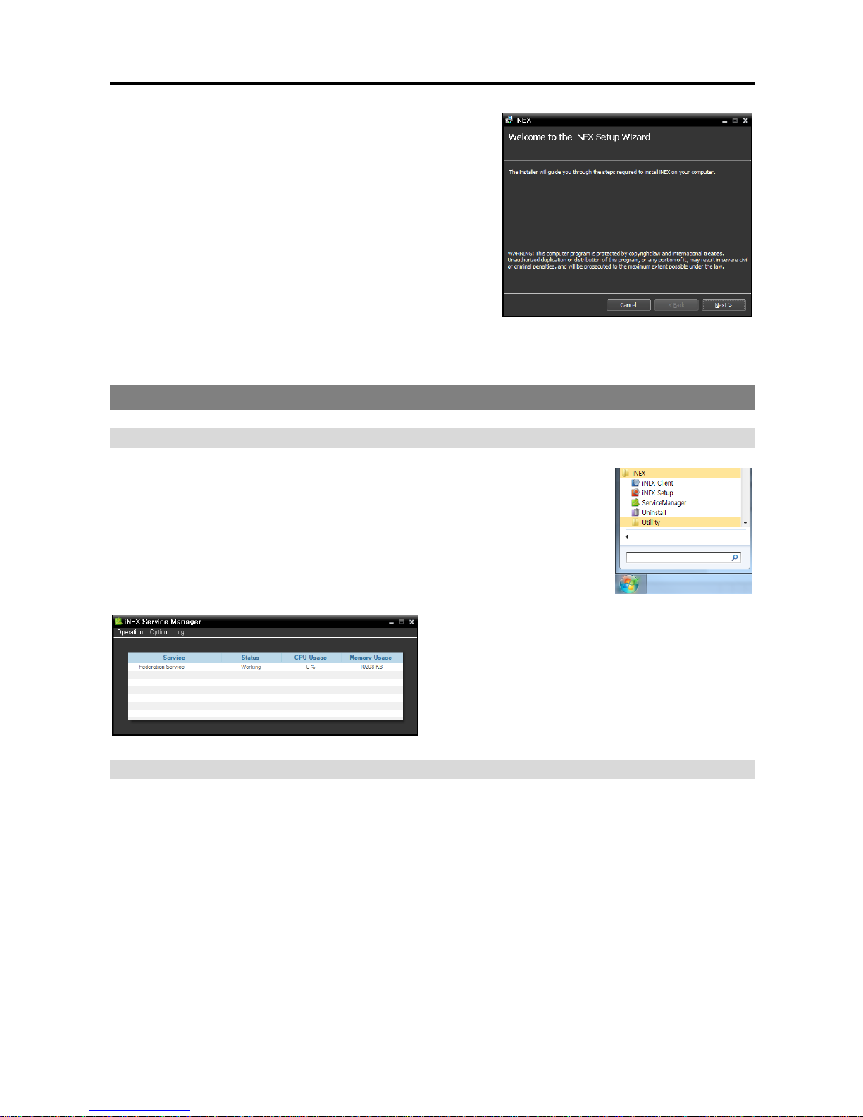
4. When the following screen appears, click Next.
Refer to the User’s Manual which is included on the CD for the setup instructions in detail.
4.2 Getting Started
Running Service
When the federation service installed, the service runs automatically. You can
also start or stop running the service manually. Go to the Start Menu in the
federation server → Click iNEX → Run the Service Manager program.
Check the status of the service. If the service is not
listed as Working under Status, start the service
manually.
Log In
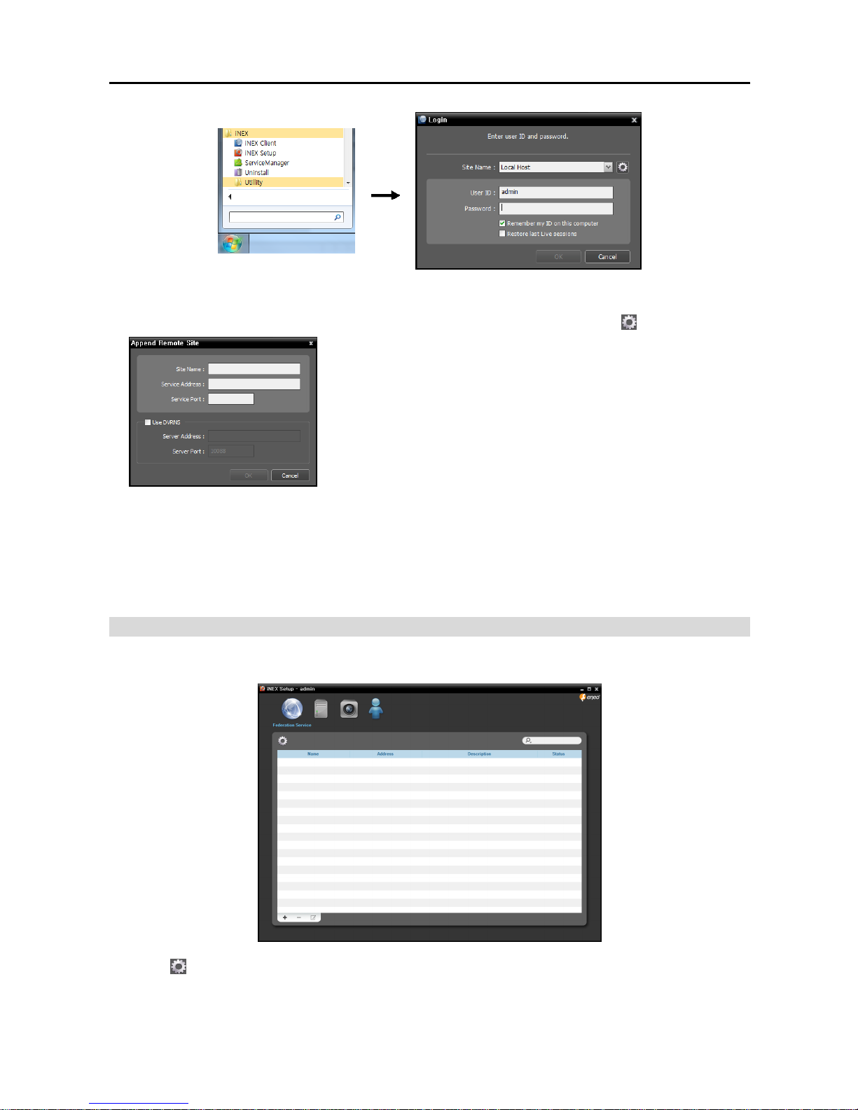
You are required to log in to the federation service when running the Setup and Client program.
Go to the Start Menu in the federation server or Client system → Click iNEX → Run the iNEX Setup or
iNEX Client program and enter login information.
Page 27
Network Video Recorder
21
Site Name: Select the federation service to connect to from the list. Select Local Host as the default
setting if the federation service is running in the current system. You can add other federation services to
the list or modify information about the federation service in the list by clicking the button at the right.
− Site Name, Service Address, Service Port: Designate the name
of the federation service and enter the IP address and port number
of the federation server (default: 11000).
User ID, Password: Enter your user ID and password. The default user ID is admin and default password
is 12345678. You can change the user ID and password in the User menu.
Remember my ID on this computer: Check the box if you want to save your ID for logging on.
Restore last Live sessions: Check the box if you want to restore the previous live monitoring sessions
in the Live panel of the Client program (supported only for the Client program).
System Setup
Run the Setup program and set up the federation server.
Click the (System Setup) button to display the system setup screen.
Page 28
Quick Reference Guide
22
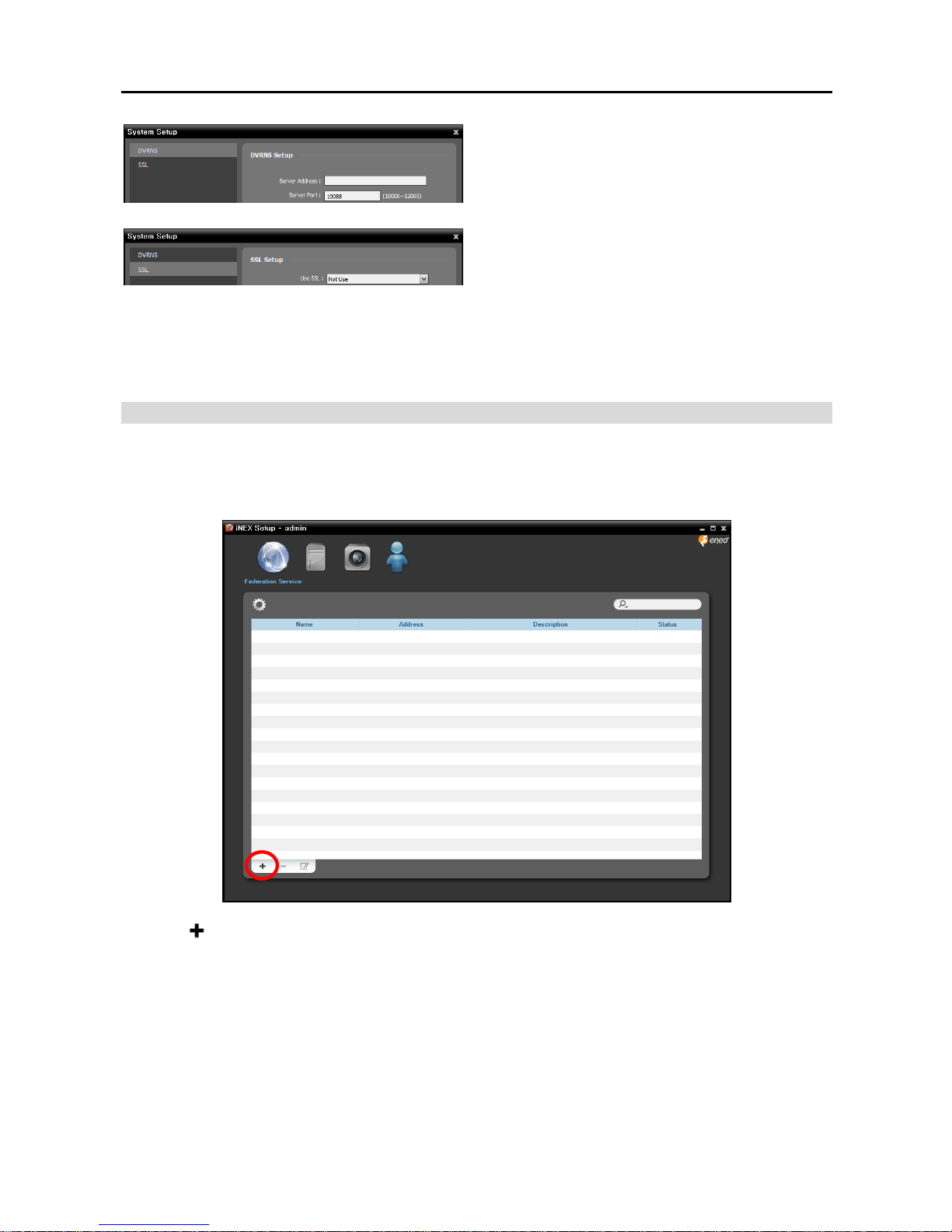
Server Address, Server Port: Enter the IP address
(domain name) and port number of the DVRNS
server that the NVR system to register is registered.
Use SSL: Allows you to enhance the security of
data transferred between services of the iNEX
program by using the SSL (Secure Sockets Layer)
protocol. Using the SSL function might cause
congestion in the federation server depending on
the security level. Log in the iNEX program again
after you change the setting. When the setting is
changed, all services that are currently connected
to the federation server reconnect, and the iNEX
Setup and iNEX Client programs are logged out.
Registering Service
You must register NVR systems (administration services) on the federation service.
Run the iNEX Setup program and enter login information.
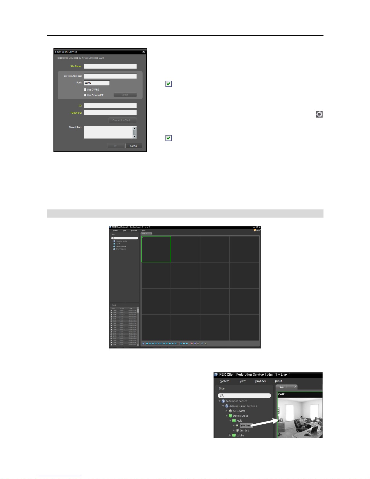
Click the button at the bottom, and the Federation Service window appears. Enter the information
for the NVR system (administration service) to register.
Page 29
Network Video Recorder
23
Site Name: Enter the name of the NVR system (administration
service).
Service Address, Port: Enter the IP address and port number
of the NVR system.
− Use DVRNS: If the NVR system uses the DVRNS
function, selecting Use DVRNS allows you to enter the NVR
system’s name registered on the DVRNS server instead of
the IP address. You can check the name in the NVR system’s
DVRNS setting (connect to the NVR system → click the
(System Setup) button in the Service menu of the iNEX Setup
program → click DVRNS).
− Use External IP: Click the Setup button and enter the
external IP address and port number of the NVR system.
ID, Password: Enter the ID and password for connection to
the NVR system. Only the users in the Administrators group
are allowed to connect to the NVR system from the federation
service.
Connection Test: Click the button to test the connection to
the NVR system with the information entered above.
Live Video Monitoring
1. Check that the NVR systems (administration services) were added to Federation Service in the Site list.
2. Click the Live tab on the tab panel → Select a site to connect
to from the Site list, and drag and drop it on the Live screen.
Live video from the selected site is displayed on the screen.
Monitoring video in the Client program of the federation
server is identical to monitoring of the NVR system
(administration service).
Page 30
Quick Reference Guide
24
Playing Recorded Video
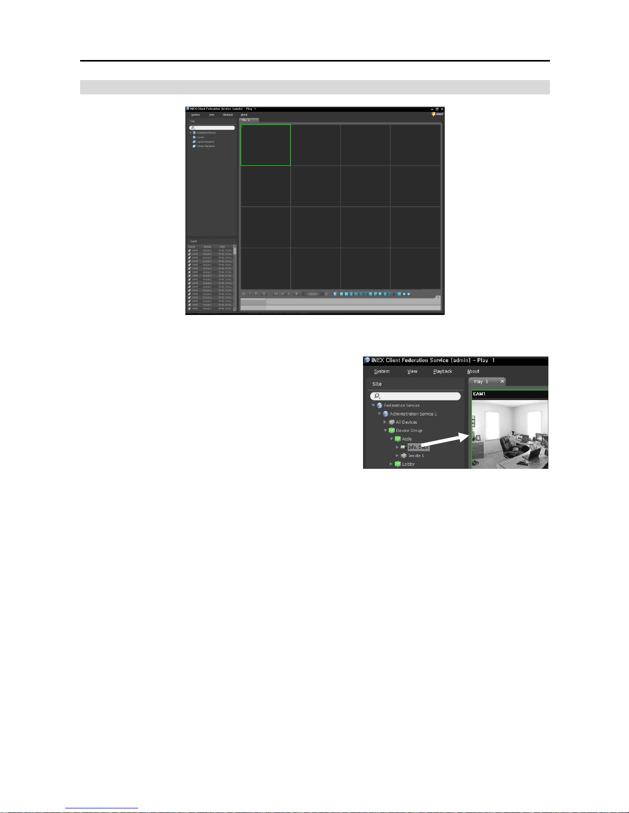
1. Check that the NVR systems (administration services) were added to a device group in the Site list.
2. Click the Play or DVR Search tab on the tab panel → Select
a site to connect to from the Site list, and then drag and drop
it on the Play or DVR Search screen. Recorded video from
the selected site is displayed on the screen. You can search
and play back recorded video by using the panel toolbar and
timetable at the bottom of the Play or DVR Search panel.
Playing back video recorded in the Client program of the
federation server is identical to playing back of the NVR
system (administration service).
Page 31

Network Video Recorder
25
Chapter 5 — Specification
VIDEO
Video Input
Network video transmitter, network camera
Supported Resolution
352x240, 704x240, 704x480, 1280x720, 1920x1080
Video Codec
H.264, MPEG-4, M-JPEG
Record Speed
(images per second)
4-ch Model: max. 120ips @ 1920x1080
8-ch Model: max. 240ips @ 1920x1080
16-ch Model: max. 320ips @ 1920x1080
CONNECTORS
Ethernet Port i
RJ-45
eSATA Port
1
USB Port
1 USB connectors
STORAGE
Primary Storage
SATA hard disk drive (Expandable up to 2)
Exporting Storage
eSATA hard disk drive
GENERAL
Dimensions (W x H x D)
8.7" x 3.5" x 11.7" (220mm x 88mm x 297mm)
Unit Weight
7.9 lbs. (3.58 kg)
Shipping Weight
11.6 lbs. (5.27 kg)
Shipping Dimensions
(W x H x D)
12.8" x 7.5" x 16.4" (325 mm x 190 mm x 416 mm)
Operating Temperature
41°F to 104°F (5°C to 40°C)
Operating Humidity
0% to 90%
Power
AC 100-240V~, 50/60 Hz, 0.6-0.3A
Approvals
FCC, CE, CB, ULii
i
The network connector is not designed to be connected directly with cable or wire intended for outdoor use.
ii
CAUTION: Risk of Explosion if Battery is replaced by an Incorrect Type. Dispose of Used Batteries According to the Instructions.
This equipment is indoor use and all the communication wiring are limited to inside of the building.
Specifications are subject to change without notice.
Page 32

eneo® is a registered trademark of Videor E. Hartig GmbH
Exclusive distribution through specialised trade channels only.
Videor E. Hartig GmbH
Carl-Zeiss-Straße 8 • 63322 Rödermark, Germany
Tel. +49 (0) 6074 / 888-0 • Fax +49 (0) 6074 / 888-100
www.videor.com Technical changes reserved.
www.eneo-security.com © Copyright by Videor E. Hartig GmbH 11/2012
 Loading...