

Eneo PLD-2036PTZ Installation Manual
1/4” Network High Speed Dome, PTZ, 36x,
Day&Night
PLD-2036PTZ

Installation Guide
2
Contents
Part 1 – Installation Guide ........................................................................... 3
Part 2 – User Man ual ................................................................................. 43

Installation Guide
3
Part 1
Installation Guide
Version 3.7

Installation Guide
4
Preface
Information given in this manual was current when published. The company reserves the
right to revise and improve its products. All specifications are subject to change without
notice.
Notice
This manual provides installation information for the outdoor Integrated High
Speed Dome Camera. To work with the Dome Cameras, any installer or
technician must have the follow i ng minimum q ual i ficati o ns:
• A basic knowledge of CCTV systems and components
• A basic knowledge of electrical wiring and low-voltage electrical hookups
• A basic knowledge of network system setting
• Have read this manual completely
Copyright
Under copyright laws, the contents of this installation guide may not be copied,
photocopied, translated, reproduced or reduced to any electronic medium or
machine-readable format, in whole or in part, without prior written permission of
the company.
Important Information
Before proceeding, please read and observe all instructions and warnings in this
manual. Retain this manual with the original bill of sale for future reference and,
if necessary, warranty service. When unpacking your unit, check for missing or
damaged items. If any item is missing, or if damage is evident, DO NOT
INSTALL OR OPERATE THIS PRODUCT. Contact your dealer for assistance.
Installation Guide
5
Regulation
This device complies with Part 15 of the FCC Rules.
Operation is subject to the following two conditions:
(1) this device may not caus e harm ful i nter ference, a nd ( 2) this
device must accept any interference received, including
interference that may cause undesired operation.
This symbol on the product or on its packaging indicates that
this product shall not be treated as household waste in
accordance with Directive 2002/96/EC. Instead it shall be
handed over to the applicable collection point for the recycling
of electrical and electronic equipment. By proper waste
handling of this product you ensure that it has no negative
consequences for the environment and human health, which
could otherwise be caused if this product is thrown into the
garbage bin. The recycling of materials will help to conserve
natural resources.
For more details information about recycling of this product,
please contact your local city office, your household waste
disposal service or the shop where you purchased the
product.
Compliance is evidenced by written declaration from our
suppliers, assuring that any potential trace contamination
levels of restricted substances are below the maximum level
set by EU Directive 2002/95/EC, or are exempted due to their
application.

Installation Guide
6
Safety Instructions
• Read these safety instructions and the operation manual first before you install and
commission the camera.
• Keep the manual in a safe place for later reference.
• Protect your camera from contamination with water and humidity to prevent it from
permanent damage. Never switch the camera on when it gets wet. Have it checked at an
authorized service center in this case.
• Never operate the camera outside of the specifications as this may prevent the camera
functioning.
• Do not operate the cameras beyond their specified temperature, humidity or power
ratings.
• Operate the camera only at a temperature range of -40°C to +50°C and at a humidity of
max. 90%.
• To disconnect the power cord of the unit, pull it out by the plug. Never pull the cord itself.
• Pay attention when laying the connection cable and observe that the cable is not subject
to heavy loads, kinks, or damage and no moisture can get in.
• Do not attempt to disassemble the camera board from the dome.
• The warranty becomes void if repairs are undertaken by unauthorized persons.
Do not open the camera housing.
• Never point the camera towards the sun with the aperture open.
This can destroy the sensor.
• Installation, maintenance and repair have to be carried out only by authorized service
centers. Before opening the cover disconnect the unit from mains input.
• Contact your local dealer in case of malfunction.
• Only use original parts and original accessories from Videor E. Hartig GmbH.
• Do not use strong or abrasive detergents when cleaning the dome.
Use a dry cloth to clean the dome surface.In case the dirt is hard to remove, use a mild
detergent and wipe gently.
• All openings provided in the housing for assembly purposes must be closed and/or
sealed.
• The installer is responsible for ensuring that the degree of protection as per the
technical specifications is upheld, e.g. by using all enclosed gasket seals and
O-rings, by waterproofing the cable exits with silicon or through laying the cable in
such a way that the cable does not act as a „gutter”.
• During assembly, care must be taken to ensure that existing seals are correctly
inserted and are not displaced as a result of assembly.
You must not continue to use damaged seals.
NOTE:
This is a class A digital device. This digital device can cause harmful interference in
a residential area; in this case the user may be required to take appropriate
corrective action at his/her own expense.

Installation Guide
7
Table of Contents – Part 1
1. Introduction .......................................................................................................................... 8
2. Standard Package Contents ............................................................................................... 9
3. Camera Setups and Cable Connections .......................................................................... 10
3.1 Preparations for Dome Camera Setups .................................................................... 10
3.2 Dome Camera Setups .............................................................................................. 13
3.2.1 Switch Definition ......................................................................................... 13
3.3 Cables and Connections .......................................................................................... 14
3.3.1 22-Pin Data Cable ...................................................................................... 14
3.3.2 22-Pin Connector Definition ........................................................................ 15
3.3.3 Cable Wiring and Connection ..................................................................... 16
3.3.4 Ethernet Cable Connection ........................................................................ 17
4. Dome Camera Installation ................................................................................................. 18
4.1 Camera Dimensions ................................................................................................. 18
4.2 Optional Accessories ................................................................................................ 19
4.3 Ceiling Mounting with Straight Tube .......................................................................... 25
4.4 Wall Mount ................................................................................................................ 27
4.4.1 Compact Pendent Mount ............................................................................ 27
4.4.2 Standard Pendent Mount ............................................................................ 30
4.4.3 Wall Box Mounting ..................................................................................... 32
4.5
Corner Mount ............................................................................................................ 34
4.5.1 Corner Standard Mounting Plate/Corner Plate Mini .................................... 34
4.5.2 Corner Thin/Wide Box Mounting ................................................................. 36
4.6 Pole Mount ............................................................................................................... 38
4.6.1 Pole Thin/ Wide Direct Mounting ................................................................. 38
4.6.2 Pole Thin/Wide Box Mounting .................................................................... 40
5. System Expansion ............................................................................................................. 42
5.1 Connecting with Power Box ...................................................................................... 42

Installation Guide
8
1. Introduction
With weather resistant feature, the integrated High Speed Dome Camera is
applicable to outdoor installation. The Dome Camera supports one cabling for
easy installation, and can be integrated with various digital surveillance products,
such as DVRs, Control Keyboards, and accessories for a total surveillance
solution. In addition, large set of built-in protocols provide connectivity to other
surveillance systems. The built-in protocols include DSCP , Pelco, VCL, Philips,
AD-422, etc., which allow the integrated High Speed Dome Camera to be
integrated with other suppliers' surveillance systems.
Installation Guide
9
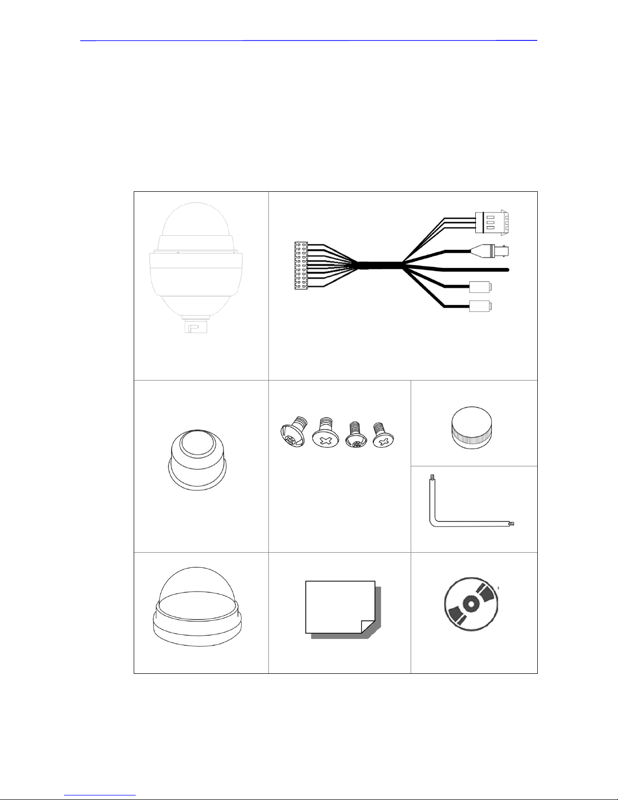
2. Standard Package Contents
Before proceeding, please check the box contains the items listed here. If any
item is missing or has defects, DO NOT install or operate the product and
contact your dealer for assistance.
Network Model
Dome Camera with
Outdoor Mount Kit
Data Cable for Power Supply, Video, Audio and Alarm
(AC 24V)
Waterproof Rubber
M3 Standard Screw (x1)
M3 Security Screw (x1)
M5 Standard Screw (x1)
M5 Security Screw (x1)
Lubricant
Security Torx
Optical Cover
Quick Guide
CD: Operation Manuals
Installation Guide
10
3. Camera Setups and Cable Connections
Before installing or connec ting the Dome Camera, please refer to this section
and complete preparations for dome setups and various switch settings.
3.1 Preparations for Dome Camera Setups
The following installation procedure is for the outdoor dome equipped with the
sunshield housing. Please follow the steps below to complete dome housing
installation.
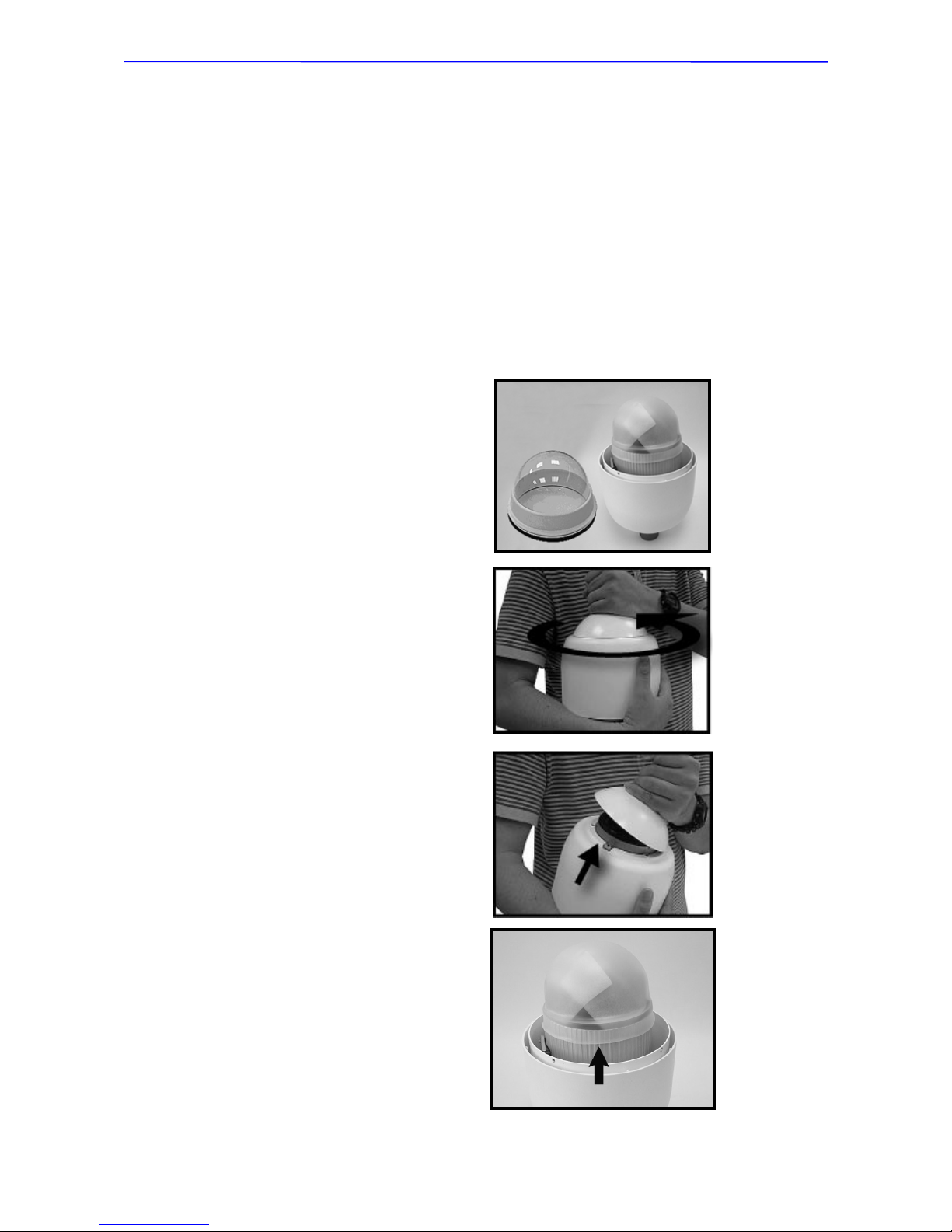
STEP 1
Unpack the Dome Camera’s
package and take out the Dome
Camera unit.
STEP 2
Rotate the Outdoor Mount Kit,
and take it off from the camera
body.
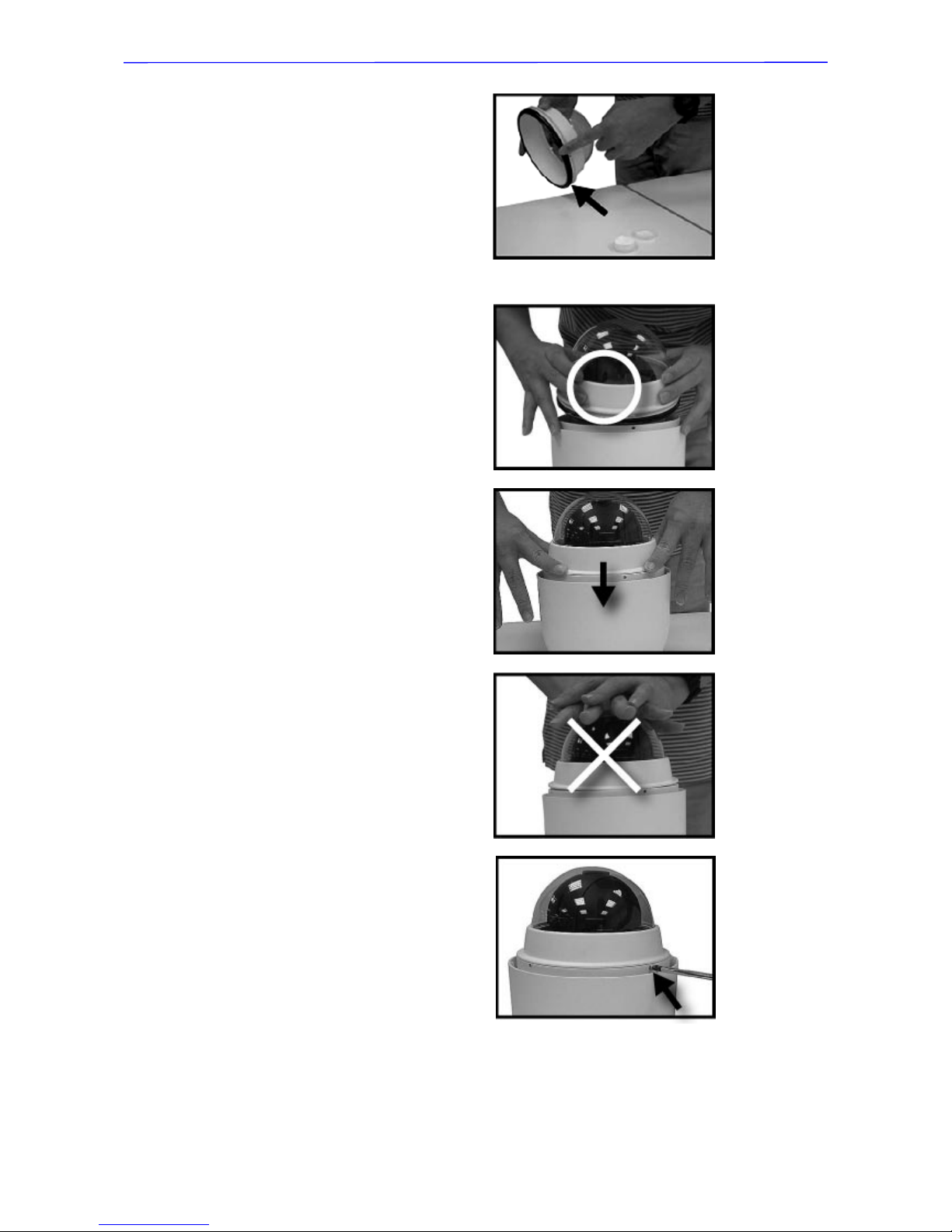
STEP 3
Remove the protectiv e cov er and
PE sheet.
Installation Guide
11
STEP 4
A
ttach the dome cover to the
camera body. Before doing
that, apply some lubricant on
the cover’s water-proof rubber
to make the installation
process smoother.
Note that the tiny protrusion on
the dome cover must align with
one of the four holes on the
dome body.
STEP 5
Gently pressure the dome
cover downward with two
hands on the side of it.
DO NOT press the cover, as
shown in the figure; this might
cause damage to the camera
body.
STEP 6
Screw the dome cover and
camera body together.

Installation Guide
12
STEP 7
Set the switches located on the
bottom of the dome body. Refer
to section 3.2 Dome Camera
Setups for detailed information
about various switch setting.
Installation Guide
13
3.2 Dome Camera Setups
Before connecting the Dome Camera to other devices of CCTV system, please
complete the Dome Camera’s ID and communication switch settings. These
switches are located on the bottom of the Dome Camera.
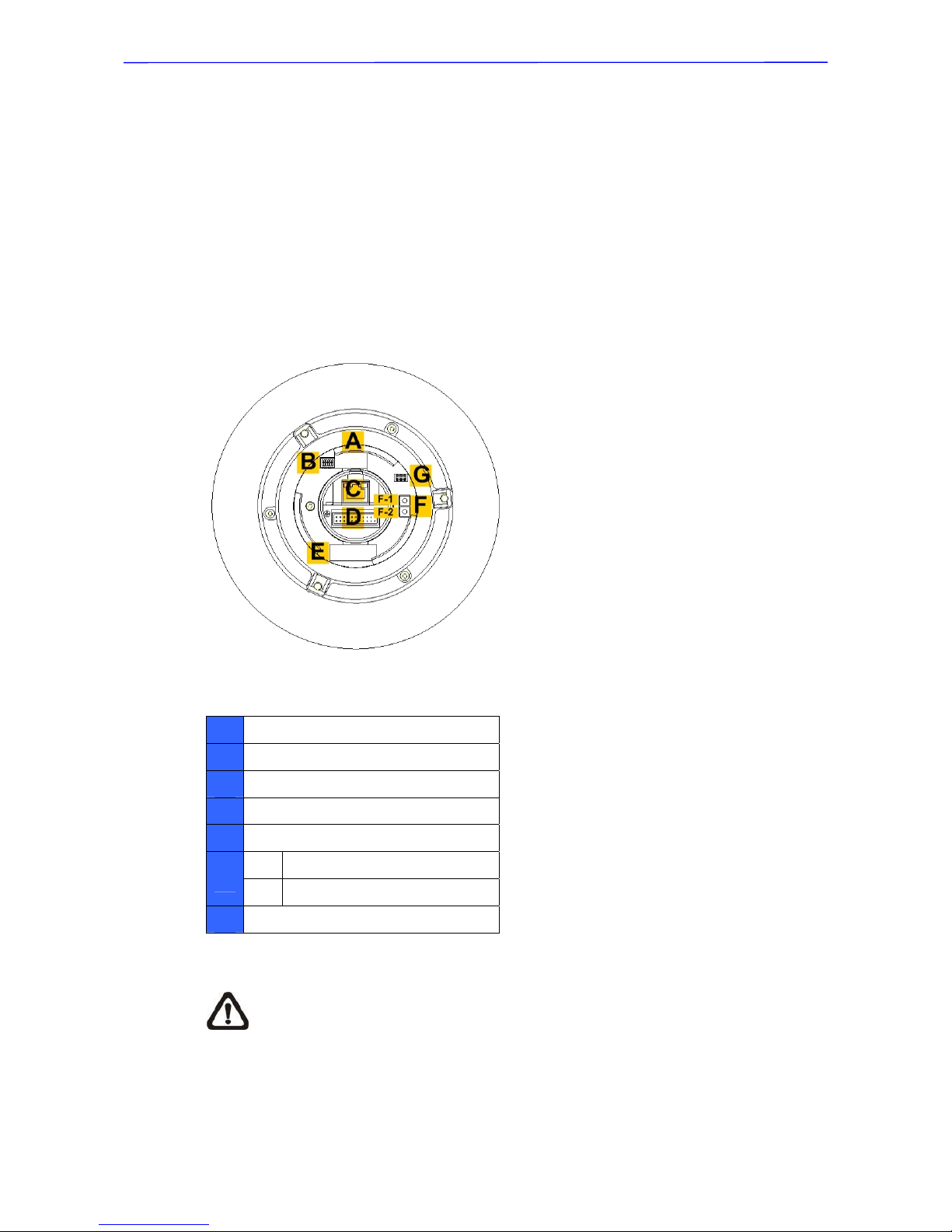
3.2.1 Switch Definition
Please refer to the diagram and table accompanied with for use of each
switch/connector.
Network Model
A
None
B
Communication Switch (Reserved)
C
RJ-45 Connector
D
22-Pin Connector
E
None
F
F-1 Reboot Button
F-2 Factory Reset Button
G
ISP Connector (for FW upgrade)
NOTE: DO NOT change the network Speed Dome Camera’s
Communication Switch factory default settings.
Installation Guide
14
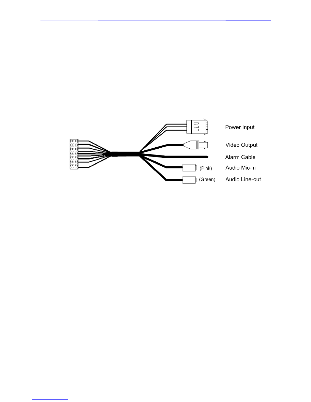
3.3 Cables and Connections
3.3.1 22-Pin Data Cable
The analog and network Speed Dome Camera’s Data Cables are illustrated
respectively as shown below.
The network Speed Dome Camera’s Data Cable is illustrated as follows.
Installation Guide
15
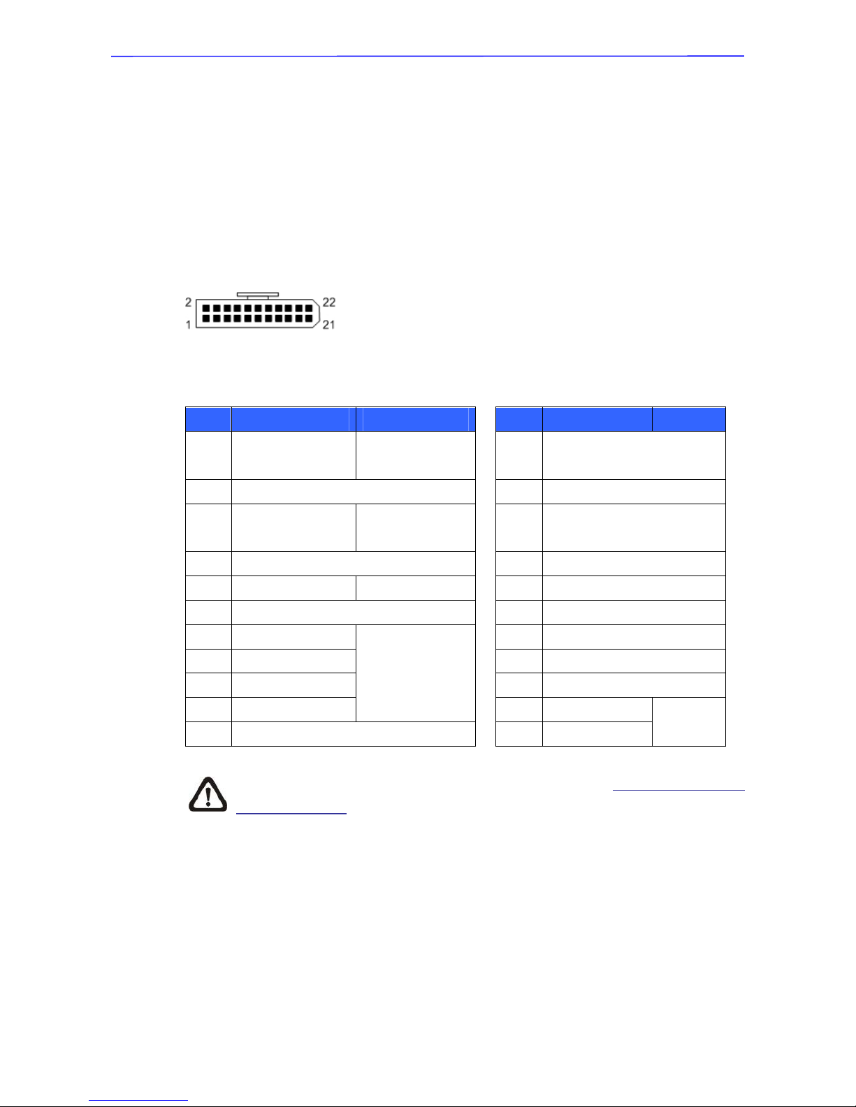
3.3.2 22-Pin Connector Definition
With the 22-pin connector, installers can simply connect the power, video and
RS-485 cables to the Dome Camera at once. Particularly, the alarm pins are
serviceable for connecting alarm input and output devices, such as alarm
sensors, sirens or flashing lights with the surveillance system. The analog and
network Speed Dome Cameras’ 22-pin connector definition will also be specified
as follows.
The network Speed Dome Camera’s 22-pin connector definition is listed below:
Pin Definition Cable
Pin Definition Cable
1
AC 24-1/DC (+)
20AWG
12
ALM-1
2
ALM NC
13
ALM-3
3
AC 24-2/DC (-)
20AWG
14
ALM-2
4
ALM NO
15
ALM-4
5
FG 20AWG
16
Reserved
6
ALM COM
17
Reserved
7
Audio in
24AWG
18
Reserved
8
Audio out
19
Reserved
9
Audio GND
20
ALM GND
10
Audio GND
21
VGND
24AWG
11
ISOG
22
Video
NOTE: For alarm connection, please refer to section 3.3.3 Cable Wiring
and Connection.
Installation Guide
16
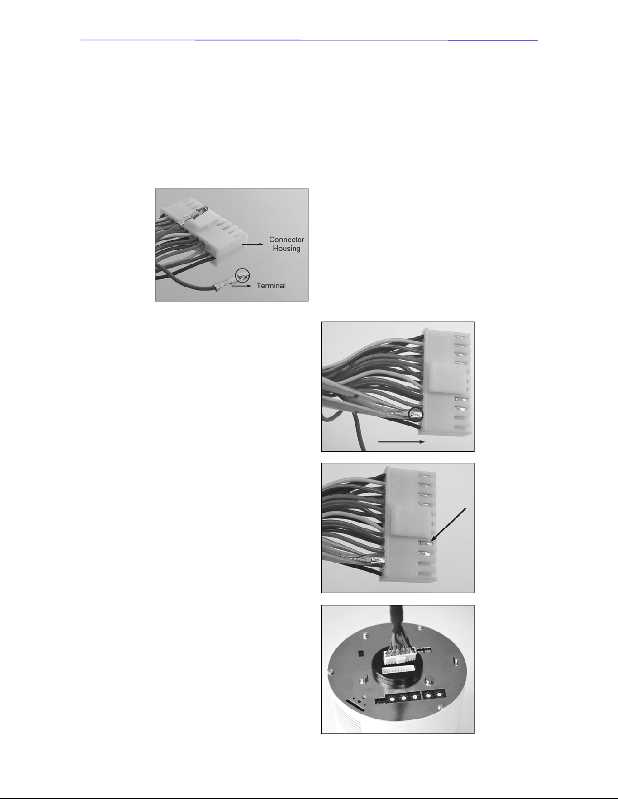
3.3.3 Cable Wiring and Connection
Users may need to conduct cable wiring when: (1) Connecting self-provided
cords to the connector housing instead of using the equipped Data Cable or (2)
Connecting alarm input and output devices. The table follows will illustrate the
way to wire cords into the connector housing.
Insert the terminal into the pin
holes on the connector
housing, with the hook
outward, as indicated in the
figure.
To unlock the terminal, press
the hook, as indicated in the
figure, with a proper tool and
pull it out gently.
Connect the 22-pin connector
to the Dome Camera.

Installation Guide
17
3.3.4 Ethernet Cable Connection
Connect one end of the CAT 5 Ethernet cable to the RJ-45 connector of the
network Speed Dome Camera, and the other end of the cable to the network
switch or PC.
NOTE: In some cases, you may need use an Ethernet crossover
cable when connecting the network Speed Dome Camera directly to
the PC.
Installation Guide
18
4. Dome Camera Installation
Basing on user’s installation environments, the Dome Camera can be installed
on ceiling, on wall or on pole. In the following section, vario us Dome Camera’s
installation accessories, installation methods and installation proced ures will be
described in detail. In addition, the next section will provide the Dome Camera’s
dimensions for your reference before installation.
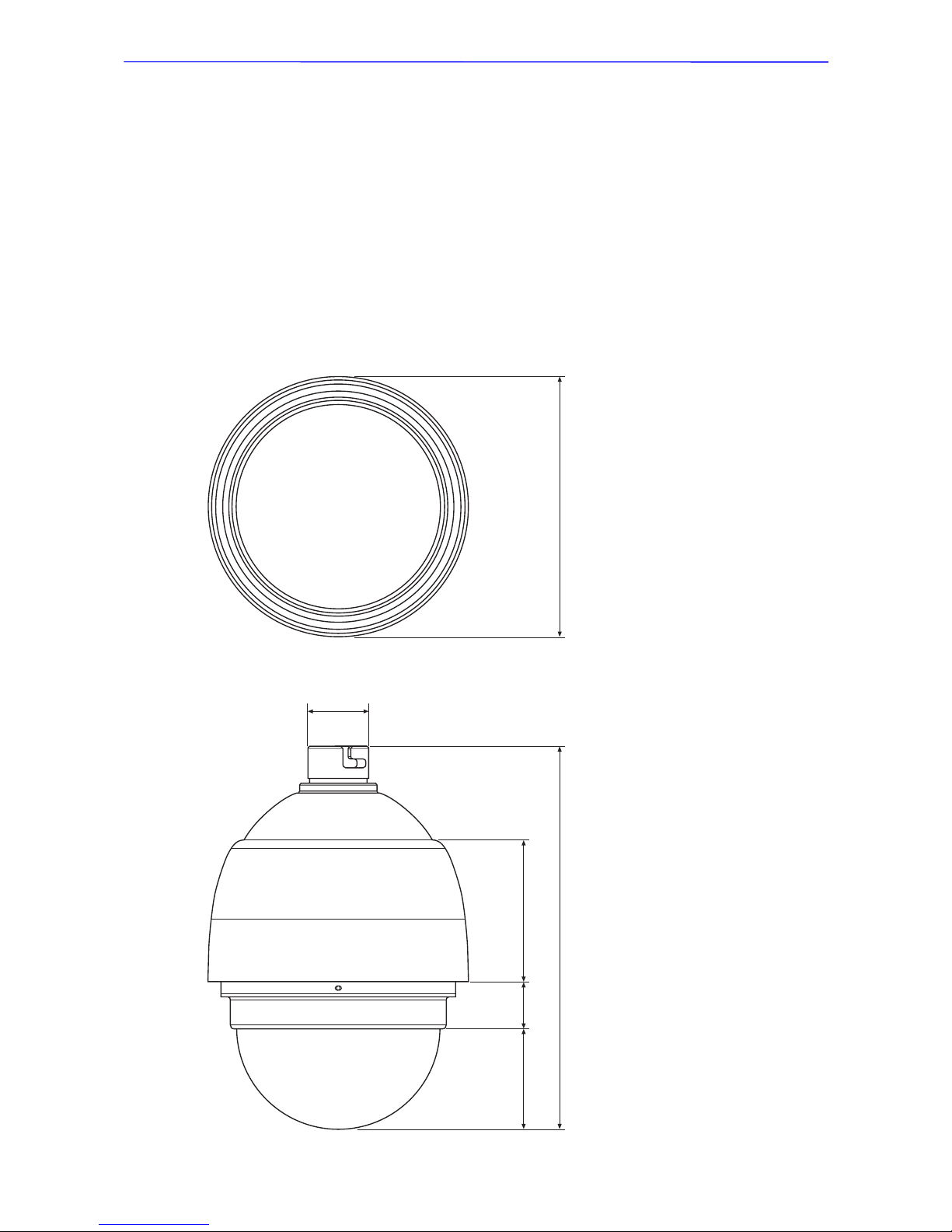
4.1 Camera Dimensions
Dimensions: mm
192
282.4
103.473.5 35.8
44.5
Installation Guide
19
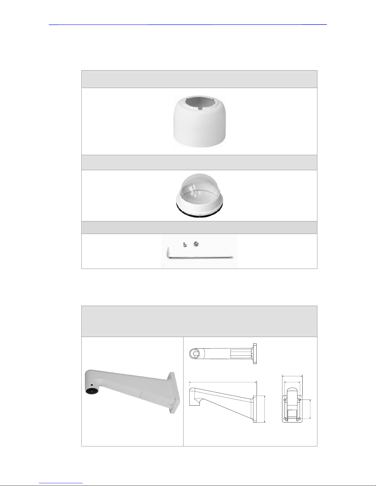
4.2 Optional Accessories
Dome Camera Accessories
Sunshield
Height: 129.5 mm (5.05 inches); Diameter: 190 mm (7.48 inches); 0.15 kg (0.33 lbs)
Transparent/Vandal Proof Cover
Diameter: 147 mm (5.8 inches)
Security Screw Set (equipped with Vandal Proof Cover)
Mounting Accessories
Standard Pendent Mount (Art. No. 200825)
White; 348×104×138.6 mm (13.7×4.1×5.5 inches); 1.5 kg (3.3 lbs); Diameter: 45 mm
(1.8 inches). Supplied with M8x12 screw x1, spring washer-8 x1, pendent tube washer x1,
rubber washer-8 x1 and sponge x2.
Dimensions: mm
138.6
348
98.5
81
104
Installation Guide
20
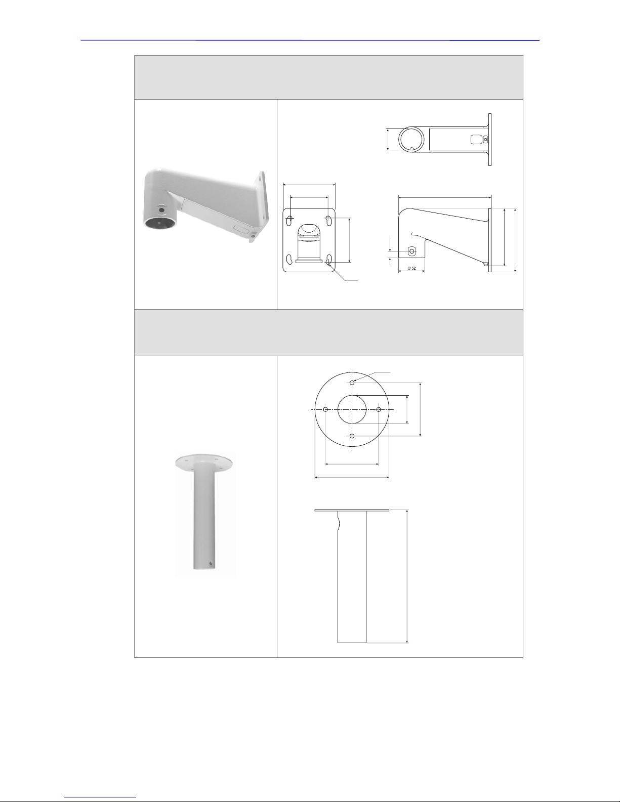
Compact Pendent Mount (Art. No. 200826)
184×104×127 mm (7.24×4.09×5 inches); 0.6 kg (1.2 lbs)
Supplied with rubber washer-8 x1, pendent tube washer x1, spring washer-8 x1 and
M8x12 screw x1.
Dimensions: mm
Straight Tube (Art. No. 200827)
Iron, Height: 250 mm (9.8 inches) ,Diameter: 50 mm (2 inches)
1 kg (2.2 lbs), Supplied with M8x12 screw x1, spring washer-8 x1, pendent tube washer
x1, rubber washer-8 x1 and waterproof rubber x1.
Dimensions: mm
127
184
115.2
12.5
88.9
76.2
4x 8.5
104
45.2
250
50
100
140
100
4x 8.5
Installation Guide
21
Corner Plate Mini (Art. No. 200831)
For mounting with Compact Pendent Mount.
200(L)×90(H)×117(D) mm (7.87×3.54×4.6 inches);
Supplied with washer-8 x4, spring washer-8 x4, M8x 1 6 scr ew x4 and M8 nut x4.
Dimensions: mm
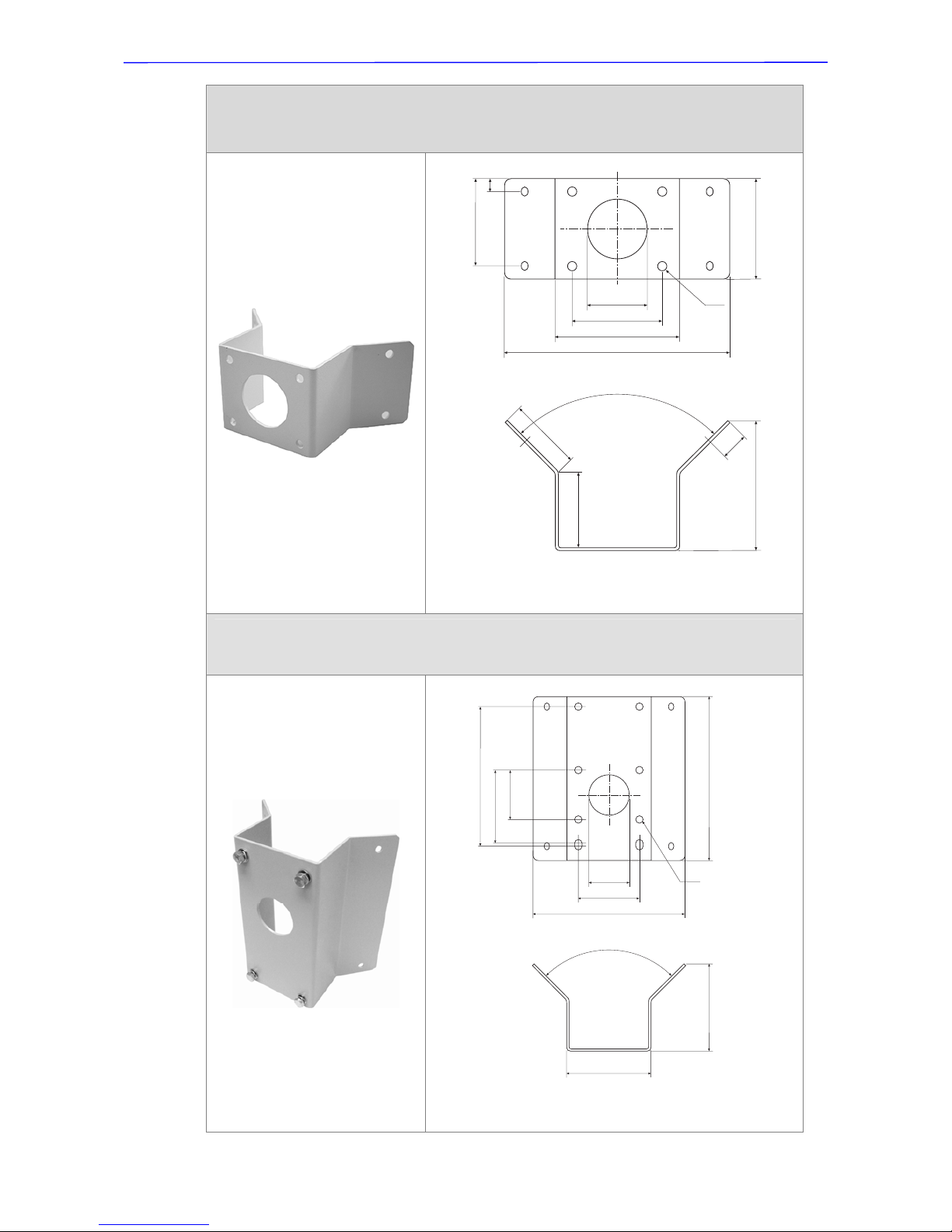
Corner Standard Mounting Plate (Art. No. 200830)
204(L)×222(H)×117(D) mm (8×8.74×4.6 inches); 2 kg (4.4 lbs);
Supplied with washer-8 x4, spring washer-8 x4, M8x 1 6 scr ew x4, and M8 nut x4.
Dimensions: mm
90°
65
68
25
117
78.5
81
11.5
8x 8.5
54
112
90
200
90°
112
117
190
81
10x 8.5
54
98.5
67
222
204
Installation Guide
22
Pole Thin Direct Mounting (Art. No. 200834)
232(H)×136(W)×50(D) mm (9.1×5.4×2 inches); Diameter: 112~130 mm (4.4~5 inches);
0.7 kg (1.6 lbs). Supplie d with stainless steel straps x 4, M8x16 screw x4, was her x4 and
spring washer-8 x4.
Dimensions: mm
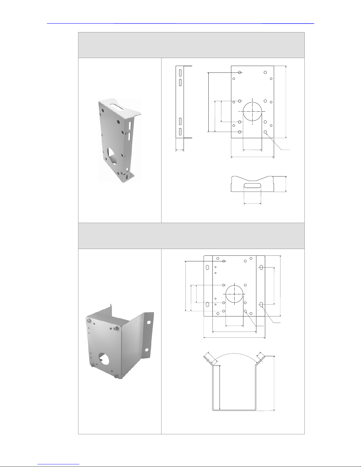
Corner Wide Box Mounting (Art. No. 200832)
232(H)×234(W)×208(D) mm (9.1×9.2×8.2 inches); 2.7 kg (6 lbs); Supplied with M8x16
screw x4, washer-8 x4, and spring washer-8 x4.
Power Box can be set inside the wide box.
Dimensions: mm
190
8x 8.5
60
98.5
67
232
136
26
54
50
90°
4
5
175
2
0
208
190
8x 8.5
65
98.5
67
232
170
140
4x 16
234
Installation Guide
23
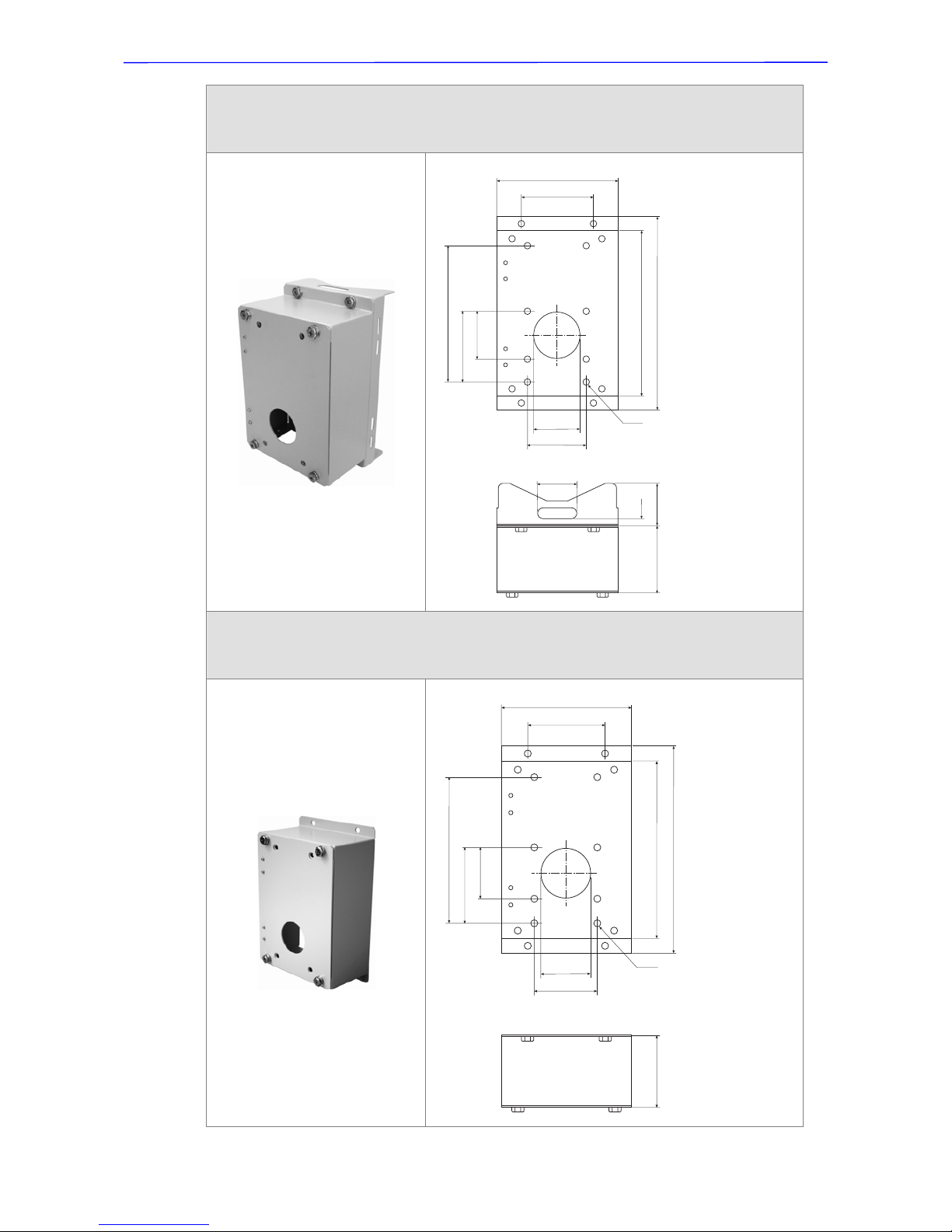
Pole Wide Box Mounting (Art. No. 200835)
270(H)×170(W)×155(D) mm (10.6×6.7×6.1 inches); 3.2 kg (7.1 lbs); Supplied with
M8x16 screw x4, washer-8 x4, spring washe r-8 x4 and stainless steel straps x4.
Power Box can be set inside the wide box.
Dimensions: mm
Wall Box Mounting (Art. No. 200829)
270(H)×170(W)×95(D) (10.6×6.7×3.7 inches); 2.2 kg (4.84 lbs);
Supplied with M8x16 screw x4, washer-8 x4 and spring washer-8 x4
Power Box can be set inside the wall box.
Dimensions: mm
190
8x 8.5
65
98.5
67
232
81
100
170
270
55
12.5
95 60
190
8x 8.5
65
98.5
67
232
81
100
170
270
95
Installation Guide
24
Stainless Steel Straps
For fixing Pole Direct Mounting / Pole Box on the pole.
Length: 650 mm (25.6 inches); Width: 12.7mm; Weight: 50g (0.1 lb)
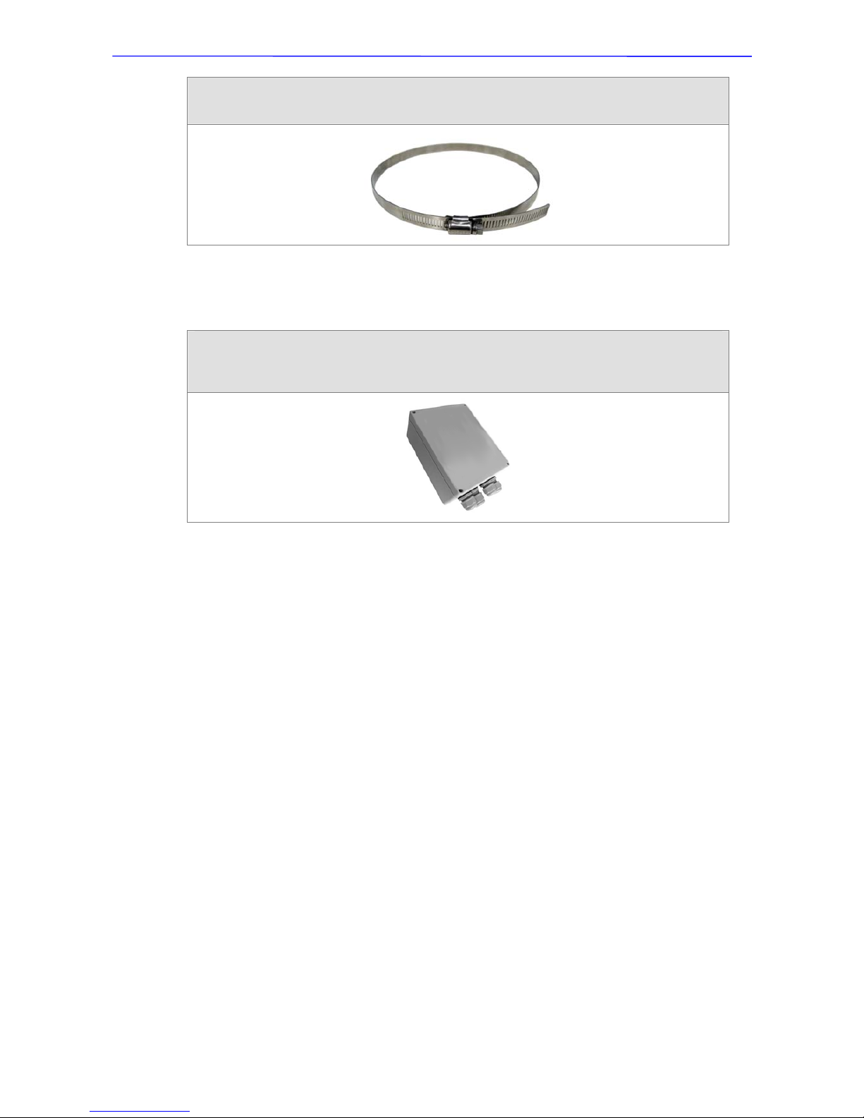
Other Application Accessories
Power Box
White, 186.5×147 mm (7.3×5.8 inches); 2.6 kg (5.8 lbs)
P1030 (Input: 110~115VAC/Output: 24VAC 72VA)
P2030 (Input: 220~230VAC/Output: 24VAC 72VA)
All photos of the accessories are subject to change without notice.

Installation Guide
25
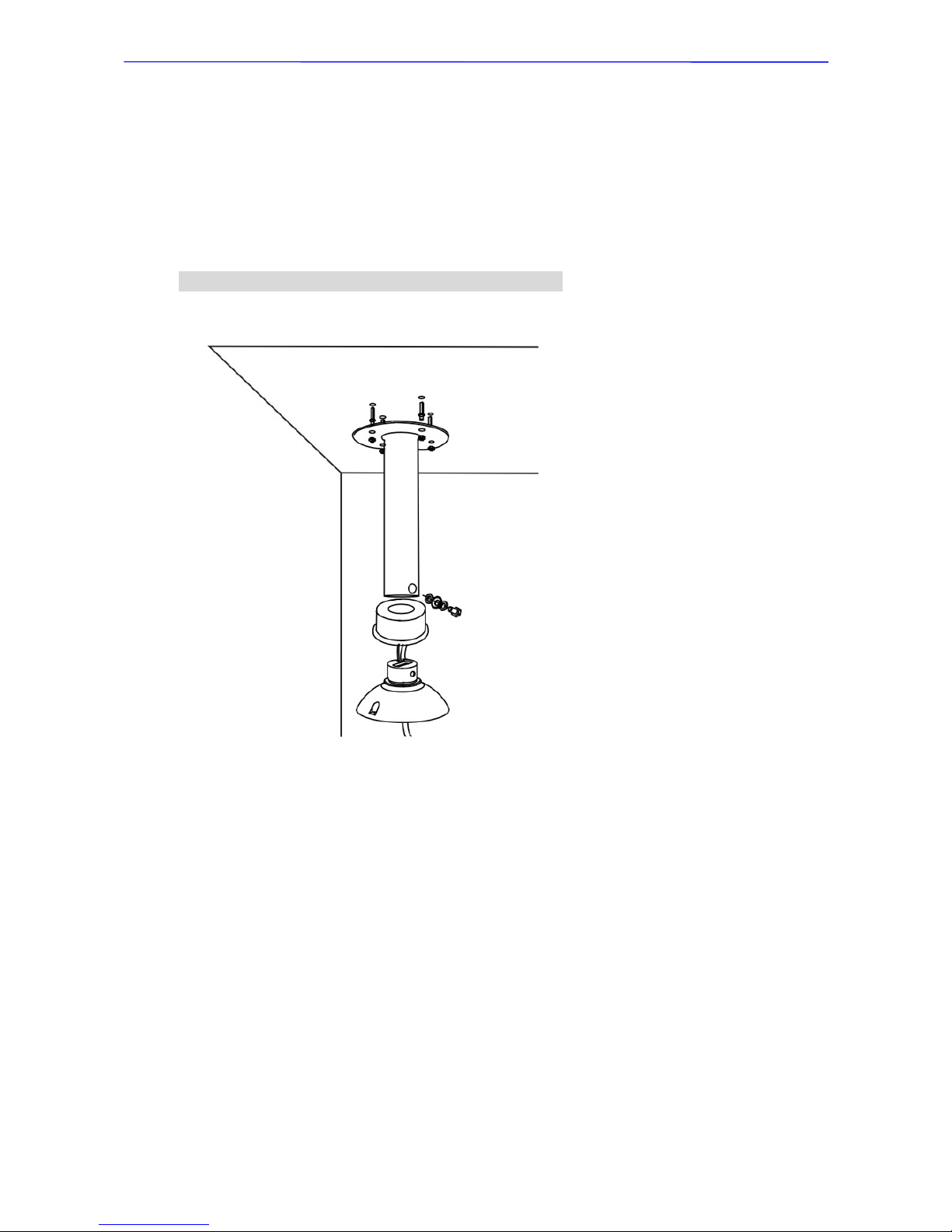
4.3 Ceiling Mounting with Straight Tube
The Straight Tube is available in different length: 25 cm and 50 cm .
Package Contents:
•
M8x12 Screw x1
•
Spring Washer-8 x1
•
Pendent Tube W asher x1
•
Rubber Washer-8 x1
•
Waterproof Rubber x1
Items Needed:
•
Dome Camera
•
Outdoor Mount Kit (supplied)
•
Data Cable (supplied)
•
Ethernet Cable (network Dome Camera)
•
Straight Tube and equipped items (optional accessory)
•
Waterproof Rubber (supplied)
•
M5 Standard/Security Screw (supplied)
•
Screws and Screw Anchors for fixing the Straight Tube onto the ceiling (not
supplied)
Tools Needed:
•
Tool for drilling
•
Tool for screwing
Follow the steps to mount the Dome Camera with the Straight Tube.
1) Ensure that the ceiling can support the weight of the Dome Camera and
Straight Tu be.
2) Make a cable entry hole on the ceiling.
3) Fix the Straight Tube to the ceiling with proper screws and screw anchors.
4) Attach the Waterproof Rubber to the Straight Tube.
5) Run the cable(s) through the Straight Tube with the Data Cable’s 22-pin
cable coming out of the outlet.
NOTE : After running the cable(s) through the Straight Tube,
please block the Tube’s outlet with the supplied sponge to avoid
insects entering the tube.
Installation Guide
26
6) Thread the cable(s) through the Outdoor Mount Kit and join the Outdoor
Mount Kit to the Straight Tube with the supplied screws and washers. Then
adjust the Waterproof Rubber to the joint.
7) Connect the cable(s) to the Dome Camera.
8) Join the Dome Camera to the Outdoor Mount Kit with the supplied M5 screw
and washers.
Ceiling Mount: Straight Tube + Outdoor Mount Kit

Installation Guide
27
4.4 Wall Mount
The Dome Camera can be mounted on the wall with Compact Pendent Mount,
Standard Pendent Mou nt and Wall Box. Pleas e follow the installatio n instructi ons
below for mounting the Dome Camera via different ways.
4.4.1 Compact Pendent Mount
Package Contents:
•
Rubber Washer-8 x1
•
Pendent Tube W asher x1
•
Spring Washer-8 x1
•
M8x12 Screw x1
Items Needed:
•
Dome Camera
•
Outdoor Mount Kit (supplied)
•
Data Cable (supplied)
•
Ethernet Cable (network Dome Camera)
•
Compact Pendent Mount and equipped items (optional accessory)
•
Waterproof Rubber (supplied)
•
M5 Standard/Security Screw (supplied)
•
Screws and Screw Anchors for fixing the Compact Pendent Mount (not
supplied)
Tools Needed:
•
Tool for drilling
•
Tool for screwing
Follow the steps below to mount the Dome Camera with the Compact Pendent
Mount.
Installation Guide
28
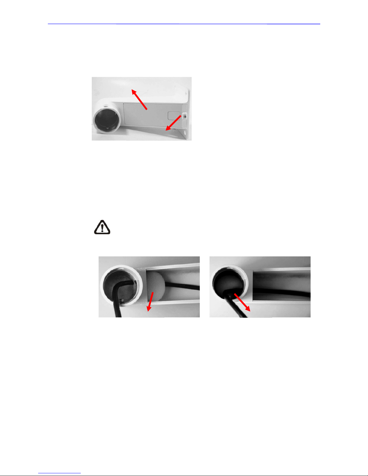
1) Make a cable entry hole on the wall to recess the cables. Otherwise, users
could push up the Cable Entry Board on the Compact Pendent Mount’s
Mounting Plate to place the cables, as shown in the photo below.
2) Fix the Compact Pendent Mount on the wall with proper screws and screw
anchors.
3) Attach the Waterproof Rubber to the Compact Pendent Mount.
4) Run the cable(s) through the Compact Pend ent Mount with the Data Cable’s
22-pin cable coming out of the outlet.
NOTE: Please block the cable entry hole with the supplied sponge
to avoid insects entering the Pendent Mount. The sponge can be
placed in two ways as shown in the illustrations below.
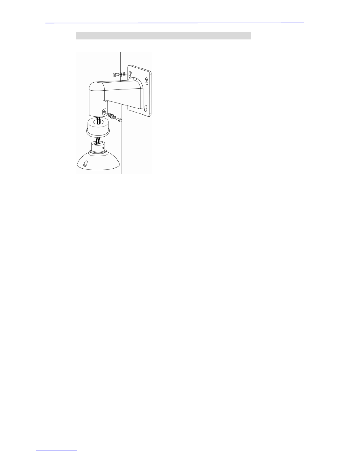
5) Thread the cable(s) through the Outdoor Mount Kit and join the Outdoor
Mount Kit to the Compact Pendent Mount with the supplied screws and
washers. Then adjust the Waterproof Rubber to the joint.
6) Connect the cable(s) to the Dome Camera.
7) Join the Dome Camera to the Outdoor Mount Ki t with the supplied M5 screw
and washers.
Cable Entry Board
Mounting Plate
Sponge
Sponge
Installation Guide
29
Wall Mounting: Compact Pendent Mount + Outdoor Mount Kit

Installation Guide
30
4.4.2 Standard Pendent Mount
Package Contents:
•
M8x12 Screw x1
•
Spring Washer-8 x1
•
Pendent Tube W asher x1
•
Rubber Washer-8 x1
•
Sponge x2
Items Needed:
•
Dome Camera
•
Outdoor Mount Kit (supplied)
•
Data Cable (supplied)
•
Ethernet Cable (network Dome Camera)
•
Standard Pendent Mount and equipped items (optional accessory)
•
Waterproof Rubber (supplied)
•
M5 Standard/Security Screw (supplied)
•
Screws and Screw Anchors for fixing the Standard Pendent Mount onto the
ceiling (not supplied)
Tools Needed:
•
Tool for drilling
•
Tool for screwing
Follow the steps below to mount the Dome Camera with the Standard Pendent
Mount.
1) Make a cable entry hole on the wall to recess the cables. Otherwise, users
could push up the cable entry board on the Standard Pendent Mount’s
mounting plate to place the cables (see the illustration in section 4.4.1
Compact Pendent Mount > Step 1).
2) Fix the Standard Pendent Mount on the wall with proper screws and screw
anchors.
3) Attach the Waterproof Rubber to the Standard Pendent Mount.
4) Run the cable(s) through the Standard Pendent Mount with the Data Cable’s
22-pin cable coming out of the outlet.
NOTE: Please block the cable entry hole with the supplied sponge
to avoid insects entering the Pendent Mount. See the illustratio ns in
section 4.4.1 Compact Pendent Mount > Step 4.
 Loading...