

Eneo NXD Series, NXD-1401M, NXD-1402M, NXD-1301M, NXD-1302M Installation Operation User Manual
1
INSTALLATION / OPERATION / USER’S MANUAL
NXD Series
MEGAPIXEL NETWORK CAMERA
2
WARNINGS AND CAUTIONS:
TO REDUCE THE RISK OF FIRE OR ELECTRIC SHOCK, DO NOT EXPOSE THIS PRODUCT TO RAIN OR
MOISTURE. DO NOT INSERT ANY METALLIC OBJECTS THROUGH THE VENTILATION GRILLS OR
OTHER OPENINGS ON THE EQUIPMENT.
CAUTION
EXPLANATION OF GRAPHICAL SYMBOLS
The lightning flash with arrowhead symbol, within an equilateral triangle, is intended to alert
the user to the presence of uninsulated "dangerous voltage" within the product's enclosure
that may be of sufficient magnitude to constitute a risk of electric shock to persons.
The exclamation point within an equilateral triangle is intended to alert the user to the
presence of important operating and maintenance (servicing) instructions in the literature
accompanying the product.
PRECAUTIONS
Safety ---------------------------------- Installation -----------------------------
Cleaning ----------------------------------
CAUTION
RISK OF ELECTRNIC SHOCK
DO NOT OPEN
CAUTION: TO REDUCE THE RISK OF ELECTRIC SHOCK,
DO NOT REMOVE COVER (OR BACK).
NO USER-SERVICEABLE PARTS INSIDE.
REFER SERVICING TO QUALIFIED SERVICE PERSONNEL.
Should any liquid or solid object fall into the cabinet,
unplug the unit and have it checked by the qualified
personnel before operating it any further.
Unplug the unit from the wall oulet if it is not going to
be used for several days or more. To disconnect the
cord, pull it out by the plug. Never pull the cord itself.
Allow adequate air circulation to prevent internal heat
build-up. Do not place the unit on surfaces (rugs,
blankets, etc.) or near materials(curtains, draperies)
that may block the ventilation holes.
Height and vertical linearity controls located at the rear
panel are for special adjustments by qualified
personnel only.
Do not install the unit in an extremely hot or humid place
or in a place subject to excessive dust, mechanical
vibration.
The unit is not designed to be waterproof.
Exposure to rain or water may damage the unit.
Clean the unit with a slightly damp soft cloth.
Use a mild household detergent. Never use strong
solvents such as thinner or benzene as they might
damage the finish of the unit.
Retain the original carton and packing materials for safe
transport of this unit in the future.

3
FCC COMPLIANCE STATEMENT
CE COMPLIANCE STATEMENT
FCC INFORMATION: THIS EQUIPMENT HAS BEEN TESTED AND FOUND TO
COMPLY WITH THE LIMITS FOR A CLASS A DIGITAL DEVICE, PURSUANT TO PART 15 OF
THE FCC RULES. THESE LIMITS ARE DESIGNED TO PROVIDE REASONABLE
PROTECTION AGAINST HARMFUL INTERFERENCE WHEN THE EQUIPMENT IS
OPERATED IN A COMMERCIAL ENVIRONMENT. THIS EQUIPMENT GENERATES, USES,
AND CAN RADIATE RADIO FREQUENCY ENERGY AND IF NOT INSTALLED AN D USED IN
ACCORDANCE WITH THE INSTRUCTION MANUAL, MAY CAUSE HARMFUL
INTERFERENCE TO RADIO COMMUNICATIONS. OPERATION OF THIS EQUIPMENT IN A
RESIDENTIAL AREA IS LIKELY TO CAUSE HARMFUL INTERFERENCE IN WHICH CASE
THE USER WILL BE REQUIRED TO CORRECT THE INTERFERENCE AT HIS OWN
EXPENSE.
CAUTION: CHANGES OR MODIFICATIONS NOT EXPRESSLY APPROVED BY THE
PARTY RESPONSIBLE FOR COMPLIANCE COULD VOID THE USER'S AUTHORITY TO
OPERATE THE EQUIPMENT.
THIS CLASS A DIGITAL APPARATUS COMPLIES WITH CANADIAN ICES-003.
CET APPAREIL NUMÉRIQUE DE LA CLASSE A EST CONFORME À LA NORME NMB-003 DU
CANADA.
WARNING
This is a Class A product. In a domestic environment this product may cause radio interference in
which case the user may be required to take adequate measures.

4
IMPORTANT SAFEGUARDS
1. READ INSTRUCTIONS -- All the safety and operating instructions should be read before the
appliance is operated.
2. RETAIN INSTRUCTIONS -- The safety and operating instructions should be retained for future
reference.
3. CLEANING -- Unplug video monitor or equipment from the wall outlet before cleaning. Do not
use liquid cleaners or aerosol cleaners. Use a damp cloth for cleaning.
4. ATTACHMENTS -- Do not use attachments not recommended by the video monitor or
equipment manufacturer as they may result in the risk of fire, electric shock or injury to persons.
5. WATER AND MOISTURE -- Do not use video monitor or equipment near water - for example,
near a bathtub, washbowl, kitchen sink, laundry tub, in a wet basement, or near a swimming
pool or the like.
6. ACCESSORIES -- Do not place video monitor or equipment on an unstable cart, stand or table.
The video monitor or equipment may fall causing serious injury to a child or adult and serious
damage to the equipment. Wall or shelf mounting should follow the manufacturer's instructions
and should use a mounting kit approved by the manufacturer.
6A. Video monitor or equipment and cart combinations should be moved with care.
Quick stops, excessive force and uneven surfaces may cause the equipment and cart
combination to overturn.
7. VENTILATION -- Slots and openings in the cabinet at the back or bottom are provided for
ventilation and to ensure reliable operation of the video monitor or equipment and to protect it
from overheating. These openings must not be blocked or covered. The openings should never
be blocked by placing the video monitor or equipment on a bed, sofa, rug, or other similar
surface. Video monitor or equipment should never be placed near or over a radiator or heat
register. Video monitor or equipment should not be placed in a built-in installation such as a
bookcase unless proper ventilation is provided.
8. POWER SOURCES -- Video monitor or equipment should be operated only from the type of
power source indicated on the marking label. If you are not sure of the type of power supplied to
your home, consult your video monitor or equipment dealer or local power company. For video
monitor or equipment designed to operate from battery power refer to the operating instructions.
9. GROUNDING OR POLARIZATION -- This video monitor may be equipped with a polarized
alternating - current line plug (a plug having one blade wider than the other). This plug will fit into
the power outlet only one way. This is a safety feature. If you are unable to insert the plug fully
into the outlet, try reversing the plug. If the plug should still fail to fit, contact your electrician to
replace your obsolete outlet. Do not defeat the safety purpose of the polarized plug. Alternate
Warnings - This video monitor is equipped with a three-wire grounding-type plug, a plug having
a third (grounding) pin. This plug will only fit into a grounding-type power outlet. This is a safety
feature. If you are unable to insert the plug into the outlet, contact your electrician to replace
your obsolete outlet. Do not defeat the safety purpose of the grounding-type plug.

5
10. POWER CORDS -- Do not allow anything to rest on the power cord. Do not locate video monitor
or equipment where the cord will be abused by persons walking on it.
11. HEED WARNINGS -- Follow all instructions marked on the video monitor or equipment.
12. LIGHTNING -- For added protection for video monitor or equipment during a lightning storm, or
when it is left unattended and unused for long periods of time, unplug it from the wall outlet and
disconnect the antenna or cable system. This will prevent damage to the video product due to
lightning and power-line surges.
13. OVERLOADING --Do not overload wall outlets and extension cords as this can result in a risk of
fire or electric shock.
14. OBJECT AND LIQUID ENTRY -- Never push objects of any kind into video monitor or
equipment through openings as they may touch dangerous voltage points or short-out parts that
could result in a fire or electric shock. Never spill liquid of any kind on the product.
15. SERVICING -- Do not attempt to service video monitor or equipment yourself as opening or
removing covers may expose you to dangerous voltage or other hazards. Refer all servicing to
qualified service personnel.
16. DAMAGE REQUIRING SERVICE -- Unplug video monitor or equipment from the wall outlet and
refer servicing to qualified service personnel under the following conditions:
A. When the power-supply cord or the plug has been damaged.
B. If liquid has spilled or objects have fallen into the video product.
C. If the video product has been exposed to rain or water.
D. If the video product does not operate normally by following the operating instructions, adjust
only those controls that are covered by the operating instructions as an improper adjustment
of other controls may result in damage and will often require extensive work by a qualified
technician to restore the video product to its normal operation.
E. If the video product has been dropped, or the cabinet damaged.
F. When the video product exhibits a distinct change in performance -- this indicates a need for
service.
17. REPLACEMENT PARTS -- When replacement parts are required, be sure the service
technician has used replacement parts specified by the manufacturer or that have the same
characteristics as the original part. Unauthorized substitutions may result in fire, electric shock or
other hazards.
18. SAFETY CHECK -- Upon completion of any service or repairs to this video product, ask the
service technician to perform safety checks to determine that the video product is in proper
operating condition.
19. FIELD INSTALLATION -- This installation should be made by a qualified service person and
should conform to all local codes.

6
CONTENTS
DESCRIPTION ----------------------------------------------------------------------------------------------------10
Key Features --------------------------------------------------------------------------------------------10
Components --------------------------------------------------------------------------------------------11
Camera Layout -----------------------------------------------------------------------------------------12
INSTALLATION ---------------------------------------------------------------------------------------------------14
Before Installation -------------------------------------------------------------------------------------14
Starting Installation ------------------------------------------------------------------------------------14
Base Installation --------------------------------------------------------------------------------------14
Heater Kit Installation (Optional) --------------------------------------------------------------------16
Heater Power Consumption --------------------------------------------------------------------------16
Micro SD card Installation (Optional) ---------------------------------------------------------------16
OPERATION -------------------------------------------------------------------------------------------------------17
Minimum conditions for using web browser -------------------------------------------------------17
Accessing the IP camera ------------------------------------------------------------------------------17
Main Menu ----------------------------------------------------------------------------------------------18
LIVE VIEW --------------------------------------------------------------------------------------------------------18
Live Video Page Icons ---------------------------------------------------------------------------------19
SETUP -------------------------------------------------------------------------------------------------------------21
Users -----------------------------------------------------------------------------------------------------22
Network -------------------------------------------------------------------------------------------------25
Image ----------------------------------------------------------------------------------------------------26
Audio -----------------------------------------------------------------------------------------------------27
Date & Time --------------------------------------------------------------------------------------------29
Live View – Source ------------------------------------------------------------------------------------31
Image – Basic ------------------------------------------------------------------------------------------33
Image – AE & AWB ------------------------------------------------------------------------------------35
Image – Day & Night ----------------------------------------------------------------------------------37
Video & Image – Stream1 ----------------------------------------------------------------------------39
Video & Image – Stream2 ----------------------------------------------------------------------------41
Video & Image – Stream3 ----------------------------------------------------------------------------44
Video & Image – Stream4 ----------------------------------------------------------------------------47
Video & Image – Webcasting ------------------------------------------------------------------------50
Audio – Basic -------------------------------------------------------------------------------------------51
Event In – Alarm-In ------------------------------------------------------------------------------------53
Event In – Manual Trigger ----------------------------------------------------------------------------55
Event In – VMD Stream1 -----------------------------------------------------------------------------56
Event In – VMD Stream3 -----------------------------------------------------------------------------58
Event In – VMD Stream4 -----------------------------------------------------------------------------60
Event Out – SMTP --------------------------------------------------------------------------------------62
Event Out – FTP& JPEG -------------------------------------------------------------------------------64

7
Event Out – Audio Alert -------------------------------------------------------------------------------66
Event Out – Audio Alert – Audio Recorder -------------------------------------------------------67
Event Out – SD Record--------------------------------------------------------------------------------69
Event Map -----------------------------------------------------------------------------------------------70
Event Map – Add ---------------------------------------------------------------------------------------71
SD Playback – SD Playback List View ---------------------------------------------------------------73
Security – Users ----------------------------------------------------------------------------------------75
Security – HTTPS --------------------------------------------------------------------------------------78
Security – IP Filtering ----------------------------------------------------------------------------------80
Date & Time ------------------------------------------------------------------------------------------- 81
Network – Basic ----------------------------------------------------------------------------------------83
Network – DDNS ---------------------------------------------------------------------------------------85
Network – RTP -----------------------------------------------------------------------------------------86
Network – UPnP ----------------------------------------------------------------------------------------88
Network – QoS ----------------------------------------------------------------------------------------89
Language -----------------------------------------------------------------------------------------------90
Maintenance --------------------------------------------------------------------------------------------91
Support --------------------------------------------------------------------------------------------------93
About ----------------------------------------------------------------------------------------------------94
Technical Specifications -----------------------------------------------------------------------------------------95
Models ---------------------------------------------------------------------------------------------------95
General --------------------------------------------------------------------------------------------------95
Electrical / Connector ----------------------------------------------------------------------------------95
Mechanical ----------------------------------------------------------------------------------------------96
Video ---------------------------------------------------------------------------------------------------97
Audio ---------------------------------------------------------------------------------------------------97
System Integration -----------------------------------------------------------------------------------97
Environmental -----------------------------------------------------------------------------------------97
Physical ------------------------------------------------------------------------------------------------97
Troubleshooting -------------------------------------------------------------------------------------------------98
Upgrading the Firmware -----------------------------------------------------------------------------98
General Troubleshooting ----------------------------------------------------------------------------98

8
LIST of ILLUSTRATIONS
Figure 1. Mounting Hole ----------------------------------------------------------------------------------------14
Figure 2. Lock Screw --------------------------------------------------------------------------------------------15
Figure 3. Mount electric box ------------------------------------------------------------------------------------15
Figure 4. Heater Kit Installation --------------------------------------------------------------------------------16
Figure 5. Heater Power Consumption -------------------------------------------------------------------------16
Figure 6. Main Live View Page ---------------------------------------------------------------------------------19
Figure 7. Basic Configuration -----------------------------------------------------------------------------------21
Figure 8. Basic Configuration / Users -------------------------------------------------------------------------22
Figure 9. Basic Configuration / Users / Add User -----------------------------------------------------------23
Figure 10. Basic Configuration / Users / Modify User -------------------------------------------------------24
Figure 11. Basic Configuration / Network --------------------------------------------------------------------25
Figure 12. Basic Configuration / Image -----------------------------------------------------------------------26
Figure 13. Basic Configuration / Audio ------------------------------------------------------------------------27
Figure 14. Basic Configuration / Date & Time ---------------------------------------------------------------29
Figure 15. Live View / Source ----------------------------------------------------------------------------------31
Figure 16. Video & Image / Image – Basic ------------------------------------------------------------------33
Figure 17. Video & Image / Image – AE & AWB ------------------------------------------------------------35
Figure 18. Video & Image / Day & Night ---------------------------------------------------------------------37
Figure 19. Video & Image / Stream1 -------------------------------------------------------------------------39
Figure 20. Video & Image / Stream2 -------------------------------------------------------------------------41
Figure 21. Video & Image / Stream2 ROI setting -----------------------------------------------------------43
Figure 22. Video & Image / Stream3 -------------------------------------------------------------------------44
Figure 23. Video & Image / Stream3 ROI setting -----------------------------------------------------------46
Figure 24. Video & Image / Stream4 -------------------------------------------------------------------------47
Figure 25. Video & Image / Stream4 ROI setting -----------------------------------------------------------49
Figure 26 Video & Image / Webcasting ----------------------------------------------------------------------50
Figure 27. Audio / Basic ----------------------------------------------------------------------------------------51
Figure 28. Event / Event In – Alarm In -----------------------------------------------------------------------53
Figure 29. Event / Event In – Manual Trigger ---------------------------------------------------------------55
Figure 30. Event / Event In – VMD Stream1 -----------------------------------------------------------------56
Figure 31. Event / Event In – VMD Stream3 -----------------------------------------------------------------58
Figure 32. Event / Event In – VMD Stream4 -----------------------------------------------------------------60
Figure 33. Event / Event Out – SMTP (Email) ---------------------------------------------------------------62
Figure 34. Event / Event Out – FTP & JPEG -----------------------------------------------------------------64
Figure 35. Event / Event Out – Audio Alert ------------------------------------------------------------------66
Figure 36. Event / Event Out – Audio Alert / Audio Recorder----------------------------------------------67
Figure 37. Event / Event Out – Audio Alert / ARecorder window -----------------------------------------67
Figure 38. Event / Event Out – Audio Alert / Encode setup -----------------------------------------------68
Figure 39. Event / Event Out – SD Record -------------------------------------------------------------------69
Figure 40. Event / Event Map ----------------------------------------------------------------------------------70
Figure 41. Event / Event Map – Add --------------------------------------------------------------------------71
Figure 42. SD Playback / Playback List View------------------------------------------------------------------73
Figure 43. SD Playback / Playback List View – Playback----------------------------------------------------74
Figure 44. System / Security – Users -----------------------------------------------------------------------75

9
Figure 45. System / Security – Users / Add User -----------------------------------------------------------76
Figure 46. System / Security – Users / Modify User --------------------------------------------------------77
Figure 47. System / Security – HTTPS ------------------------------------------------------------------------78
Figure 48. System / Security – IP Filtering -------------------------------------------------------------------80
Figure 49. System / Date & Time ------------------------------------------------------------------------------81
Figure 50. System / Network – Basic -------------------------------------------------------------------------82
Figure 51. System / Network – DDNS ------------------------------------------------------------------------85
Figure 52. System / Network – RTP ---------------------------------------------------------------------------86
Figure 53. System / Network – UPnP -------------------------------------------------------------------------88
Figure 54. System / Network – QoS -------------------------------------------------------------------------89
Figure 55. System / Language ---------------------------------------------------------------------------------90
Figure 56. System / Maintenance -----------------------------------------------------------------------------91
Figure 57. System / Support -----------------------------------------------------------------------------------93
Figure 58. About -------------------------------------------------------------------------------------------------94

10
DESCRIPTION
-------------------------------------------------------------------------------------------------------------------------------------
The NXD Series camera is an internet protocol based megapixel network camera with a built-in web
based viewer on Internet Explorer®. The camera has a connection feature for third-party
applications and compatible with supplied Utility software for easy installation and Client software to
search, configure, manage, live view, record and playback.
The camera supports dual compression formats and multiple streaming simultaneously. The two
standard compression formats include H.264 and MJPEG. The multiple streams can be configured to
a variety of resolutions, bit rates and frame rates.
The camera uses 1/2.5 inch CMOS sensor and Focal length 3~9mm lens and also supports PoE
(Power over Ethernet), DC12V, and AC24V.
Models
NXD-1401M NXD Series, 1 Megapixel, 30ips@1280x720
NXD-1402M NXD Series, 2 Megapixel, 15ips@1600x1200
NXD-1301M NXD Series, 1 Megapixel, 30ips@1280x720, Day/Night
NXD-1302M NXD Series, 2 Megapixel, 15ips@1600x1200, Day/Night
Key Features
- HDTV Video Quality
The NXD Series are capable of providing the outstanding image quality with HDTV performance and
profiles (High, Main, and Baseline) in H.264 compression.
- Multiple Streaming
Each stream can be programmed independently and transmitted using different configurations.
- ROI (Region of Interest)
ROI features that transmit specially selected area in the primary stream using different FPS,
Resolution, Bit Rates and Picture Quality.
- Easy Focus
Easy Focus helps to reduce the installation efforts especially video image focusing of the camera.
- Dual Codec (H.264, MJPEG)
The NXD Series supports two standard compressions formats H.264 and MJPEG.
- Digital PTZ

11
Supports maximum 10x digital zoom.
- Intelligent Video Motion Detection
The NXD Series offers intelligent & sophisticated video motion detection for each multiple streams.
- Triple Power (Power over Ethernet, DC12V, AC24V)
This camera supports Power over Ethernet (PoE), which supplies power to the camera through the
network. If the network has no PoE, connect a DC12V or AC24V power connector.
- Day and Night
The NXD Series provide clear monitoring images even in low light conditions using IR-cut filter.
- SD Local Recording
The NXD Series provides local video recording function. When camera detects video motion or
alarm events or manual trigger, it can record video stream by itself.
- Voice Alert Linked to Alarm Detection
The NXD Series can play the audio file stored in the camera in synchronization with alarm detection
by the sensor input or the motion detection function.
- Network Flow Control
The NXD Series provides a flow control function which enhances network efficiency by significantly
restricting user video streams with designating the maximum bandwidth.
- ONVIF Certificate
The NXD Series network camera complies with the ONVIF certificate. ONVIF (Open Network Video Interface
Forum) is an open industry forum for the development of a global standard for the interface of network video
products.
Components
Quantity Description
1 Camera
1 Installation CD
1 Accessory kit for installing Dome Camera
1 Template sheet
1 Extension connector kit
NOTE
Adapter for DC12V / AC24V are not supplied.
12
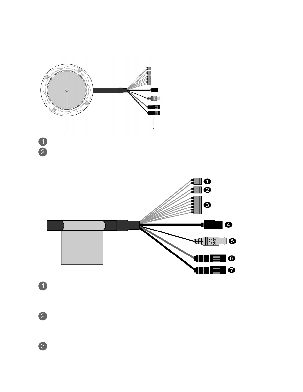
Camera Layout
Top View
Lens: Allows wide area to be monitored
Connection Cable: 26pin camera extension cable
Connection Cable
Main POWER connection
- RED; DC12V or AC24V
- WHITE; GND or AC24V
Heater POWER connection (Optional)
- ORANGE; DC12V or AC24V
- BLACK; GND or AC24V
ALARM connection
- PINK; Alarm Input 1

13
- GREEN; GND
- YELLOW; Alarm Input 2
- BROWN; GND
- Light BLUE; Alarm Out
- GRAY; GND
RJ-45 connection: Connect Ethernet cable or supplies power to the camera if PoE is
available.
BNC connection: Connect BNC cable for composite video output.
SPEAKER connection (GRAY): Connect external speaker for audio output.
MIC connection (BLACK): Supplies external microphone as an audio input source.
14
INSTALLATION
-------------------------------------------------------------------------------------------------------------------------------------
Before Installation
Before installing the camera, thoroughly familiarize yourself with the information in this section of
the manual.
- Recommends connecting the camera to a network that use a DHCP (Dynamic Host Configuration
Protocol) server to address devices.
- To ensure secure access to the IP camera, place the camera behind a firewall when it is
connected to a network.
Starting Installation
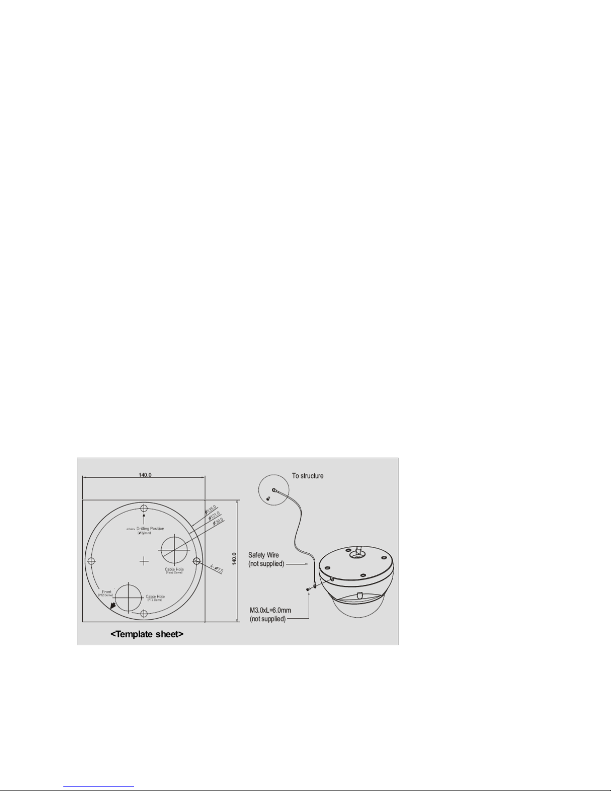
Base Installation
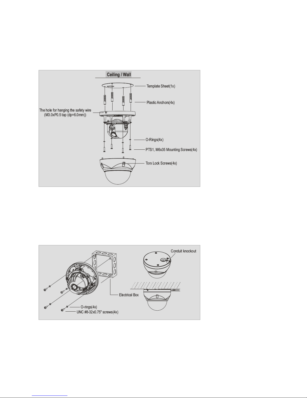
1. Make mounting holes and cable hole in the place (ceiling) to which this dome camera is installed
using the supplied template sheet.
NOTE
The total mass of the main unit is approx 1.3kg. Check whether the ceiling to which the Dome
Camera is installed is strong enough to hold the unit mass. If not, the Dome Camera could fall,
causing injury.
Figure 1. Mounting Hole
2. Attach the safety wire for securing the dome camera to ceiling or structure not to fall.
3. Extract each wire through the cable hole, connect BNC cable and communication lines.
15
4. Unlock torx screws (4x) the dome cover and fix the dome case firmly with supplied mounting
screws (4x), plastic anchors (4x), O-Rings (4x).
5. Adjust desired focus and scene by turning and moving the hemisphere by hand.
6. Lock the housing cover with torx screws (4x).
Figure 2. Lock Screw
NOTES
- Cable through the electrical box with the dome base
The housing can also be mounted on a 4s or 2s electrical box.
- Using the conduit knockout punched with the dome base
Remove the conduit knockout punched for the cable entry.
Figure 3. Mount electric box
16
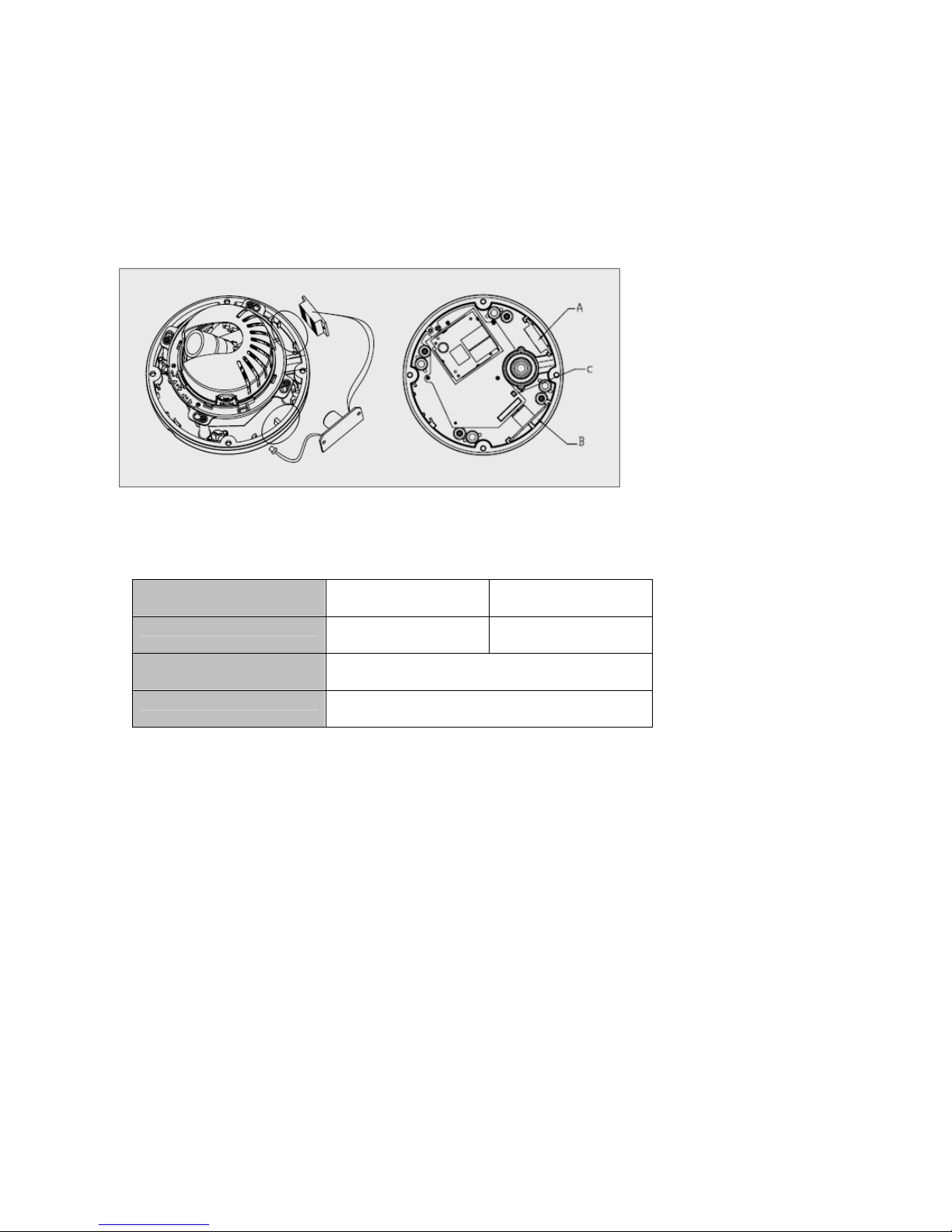
Heater Kit Installation (Optional)
1. Place the heater element is slot “A”. Please ensure that the cables are facing upwards and the
heater is pointing towards the Dome.
2. Place the PCB in slot “B”. Please ensure that the PCB is facing inside of the Dome with the
connection blocks at the top.
3. Place the plug in the Socket “C” (J3) which is found on the controller board.
Figure 4. Heater Kit Installation
NOTES
- Heater power consumption
Power Supply AC24V DC12V
Power Consumption 20Watt 10Watt
Heater On at 41°F (5°C)
Heater Off at 59°F (15°C)
Figure 5. Heater Power Consumption
- Power
Use Certified/Listed Class 2 power source only.
Micro SD Card Installation (Optional)
1. First, open the housing cover and then check the SW2 mode whether SW2 is at off mode or not.
The default setting is off mode.
2. Insert micro SD card and then move SW2 direction to on.
3. In case of SD card removal, first move SW2 direction to off mode and then remove SD card.

17
OPERATION
-------------------------------------------------------------------------------------------------------------------------------------
Before starting the camera, installation must be complete. The camera completes a configuration
sequence within approximately 40 seconds when power is supplied. The amber LED of this
megapixel camera flash one time per second indicating the configuration sequence is complete.
NOTES
- If the DHCP is enabled but the camera is not connected to a DHCP server, the camera will be set
default IP 192.168.30.220 and try to get IP from DHCP server about every two seconds.
- Network and processor bandwidth limitations might cause the video stream to pause or appear
pixilated when an increased number of Web-interface users connection to the camera. Decrease
the images per second, resolution, compression, or bit rate settings of the Web-interface video
streams to compensate for network or processor limitations.
Minimum conditions for using web browser
The minimum system requirements to use a Web browser with this IP camera are as follows:
- CPU: Pentium® 4 microprocessor, 2.0GHz
- Operational System: Windows XP® or Windows Vista® or Windows7®
- System Memory: RAM 512 Mbyte
- Ethernet: 100 Mbit
- Video Resolution: 1024(Horizontal) x 768(Vertical) pixels or higher
- Internet Explorer® 7 or later
- ActiveX® 1.0.0.13 or later
Accessing the IP camera
1. Open Web browser
- Double click Internet Explorer® icon.
2. Type IP address
- Type the camera’s IP address in the Internet Explorer® address bar.
- The default IP address is
192.168.30.220
NOTES
- If you do not know the camera’s IP address, install the SmartManager® utility software available
on the CD supplied with the product. The utility software will locate the assigned Model name,
Host name, MAC address, IP address, Version and others.
- Refer to the SmartManager® utility software manual for more detail.
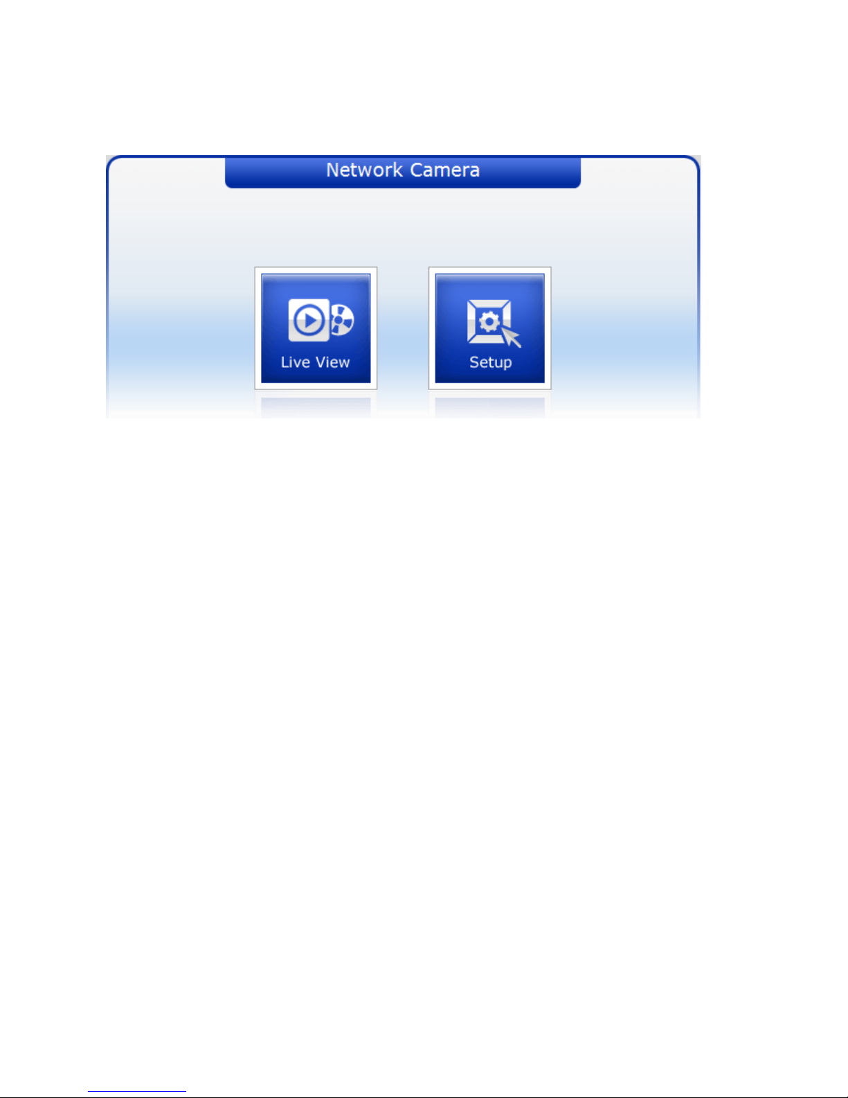
3. Log On to the camera
- Click the Live View icon for default live image view or the Setup icon to change the configuration
values.
18
Main Menu
Figure 5. Main menu
The dialog box will be appears.
- Type User ID and Password in the dialog box. The default User ID and Password is
admin
.
NOTE
For security purposes, be sure to change the password after you log on for the first time.
19
LIVE VIEW
-------------------------------------------------------------------------------------------------------------------------------------
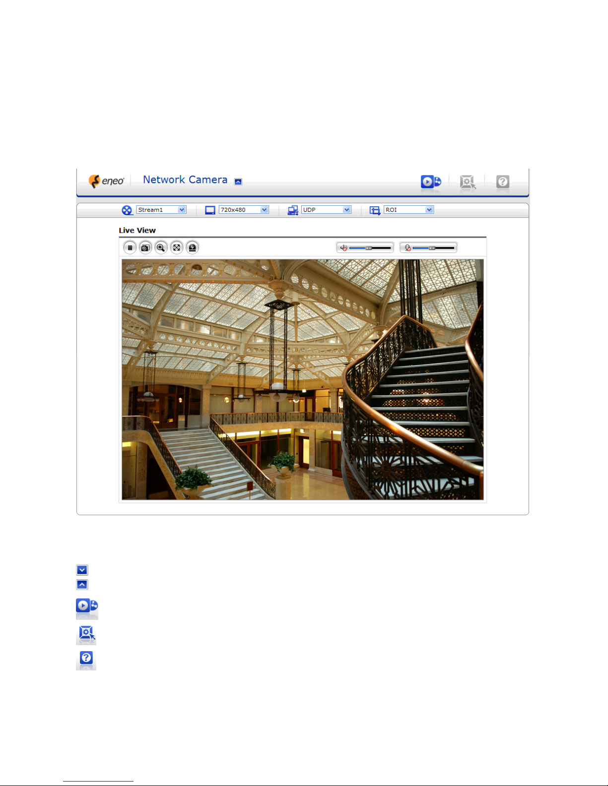
The Live View page provides you to select the properties of video source. You can view the live
image from this page and also access the Setup menu and operate the main functions.
Figure 6. Main Live View Page
Live Video Page Icons
Hide Main Icons: Hides main icons in the live view page.
Show Main Icons: Shows main icons in the live view page.
Live view: Displays live video stream.
Setup: Enters setup menu.
Help: Shows helpful information.

20
Source: Specify the viewable video stream source to display in live view page.
View Size: Specify the viewable video size to display in live view page.
Stream Type: Specify the internet protocol to display in live view page.
ROI View: Specify the specially selected area to transfer using different stream feature in the
primary video image. ROI is an abbreviation for “Region of Interest”.
Pause: Pause the live video stream.
Snapshot: Take a picture of the video image currently on display. Supports the origin image
size view, Print, and Save feature.
Digital Zoom: Supports a digital zoom in live video image.
Full Screen: Expands video image to the entire screen area.
Manual Trigger: Activates the Alarm Out signaling manually.
Speaker: Adjusts the volume of Speaker and switch the sound on / off.
Microphone: Adjusts the volume of Microphone and switch the sound on /
off.
21
SETUP
-------------------------------------------------------------------------------------------------------------------------------------
The SETUP pages provide you to manage the camera and change the setting values. For the easy
and quick access the video, the setup menu is configured two parts, which are Basic Configuration
and advanced configuration. The Basic Configuration menu allows you to setup Users, basic
Network and Image. The remaining configuration parts help to setup user dependent values and
provide more advanced settings.
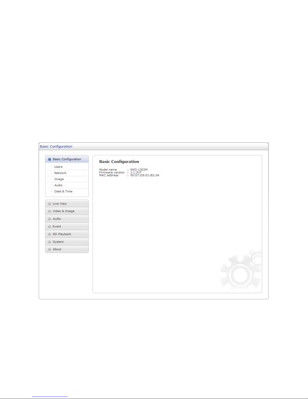
Basic Configuration
Basic Configuration supply user to access the camera image using minimum setting. Also it shows
the camera basic information such as Model name, Firmware version and MAC address.
Figure 7. Basic Configuration
NOTE
The setting menu might not be available if the user does not have the permission to access this
feature. The only required setting is the IP address, which is set on the Network page. All other
settings are available with default values and optional.
22
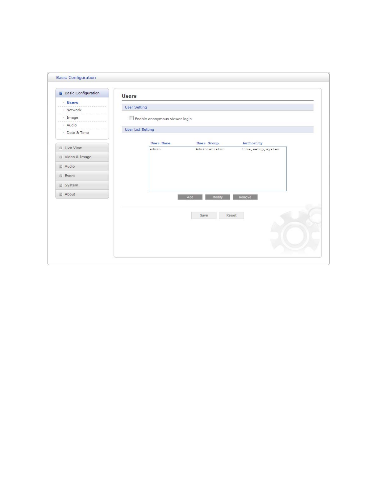
Users
Use the Users tab to manage user permission to access the camera.
Figure 8. Basic Configuration / Users
User Setting: Click the Enable anonymous viewer login checkbox to enable anonymous user
login to the camera. The default setting is disabled.
User List Setting:
User accounts can be added or modified or removed. The authority
depends upon user group automatically and shows the permission status to access the menus.
The default user name / password is
admin
.
User Name: Shows the name which registered to access the camera.
User Group:
Shows the assigned permission given to users.
Authority: Shows the permission status to access the menus.
- Click the Add, Modify, or Remove button for managing user account.
23
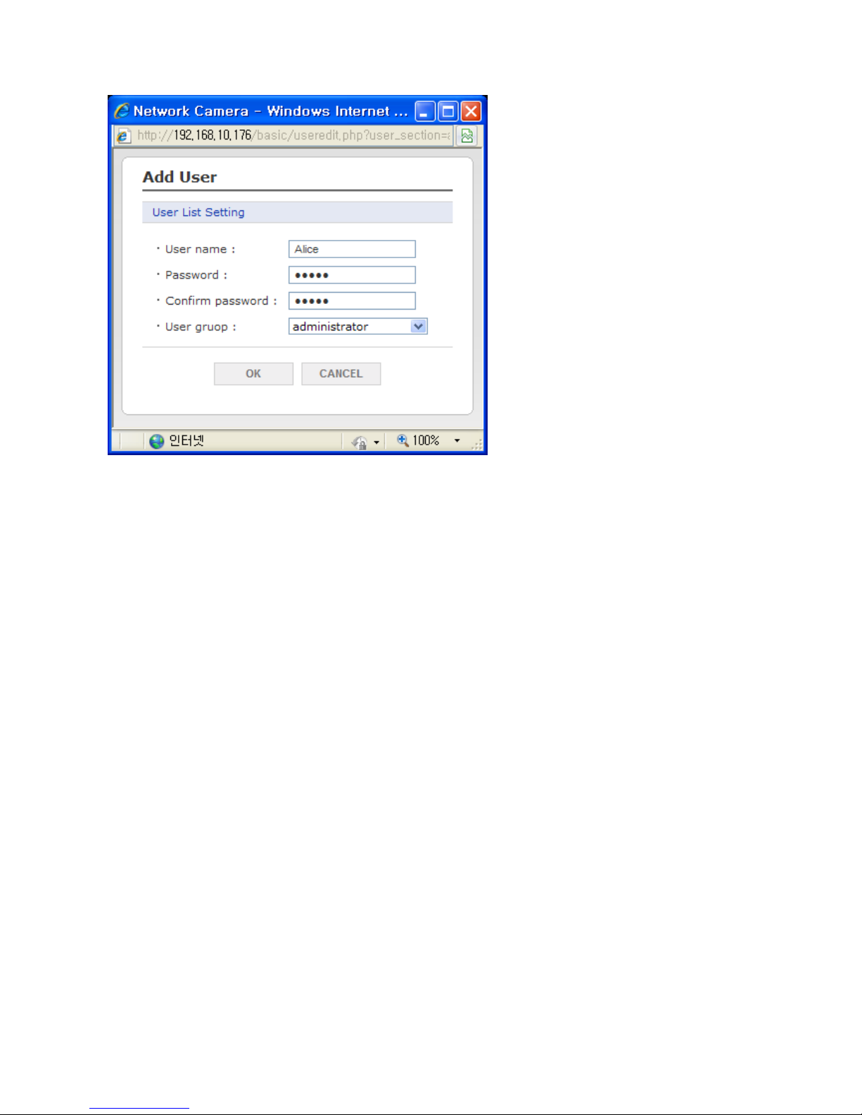
Figure 9. Basic Configuration / Users / Add User
To add a new user:
1. Click the Add tab, and then new pop-up window appears.
2. Click in the User name box and type a new user name (1 to 14 alphanumeric characters). User
names are not case sensitive.
3. Click in the Password box and type a password (1 to 8 alphanumeric characters). Passwords are
case sensitive.
4. Click in the Confirm password box and retype a password.
5. Click in the User group box and select one of the groups you wish to assign to the user.
6. Click the OK button to save the settings and add a new user.
24
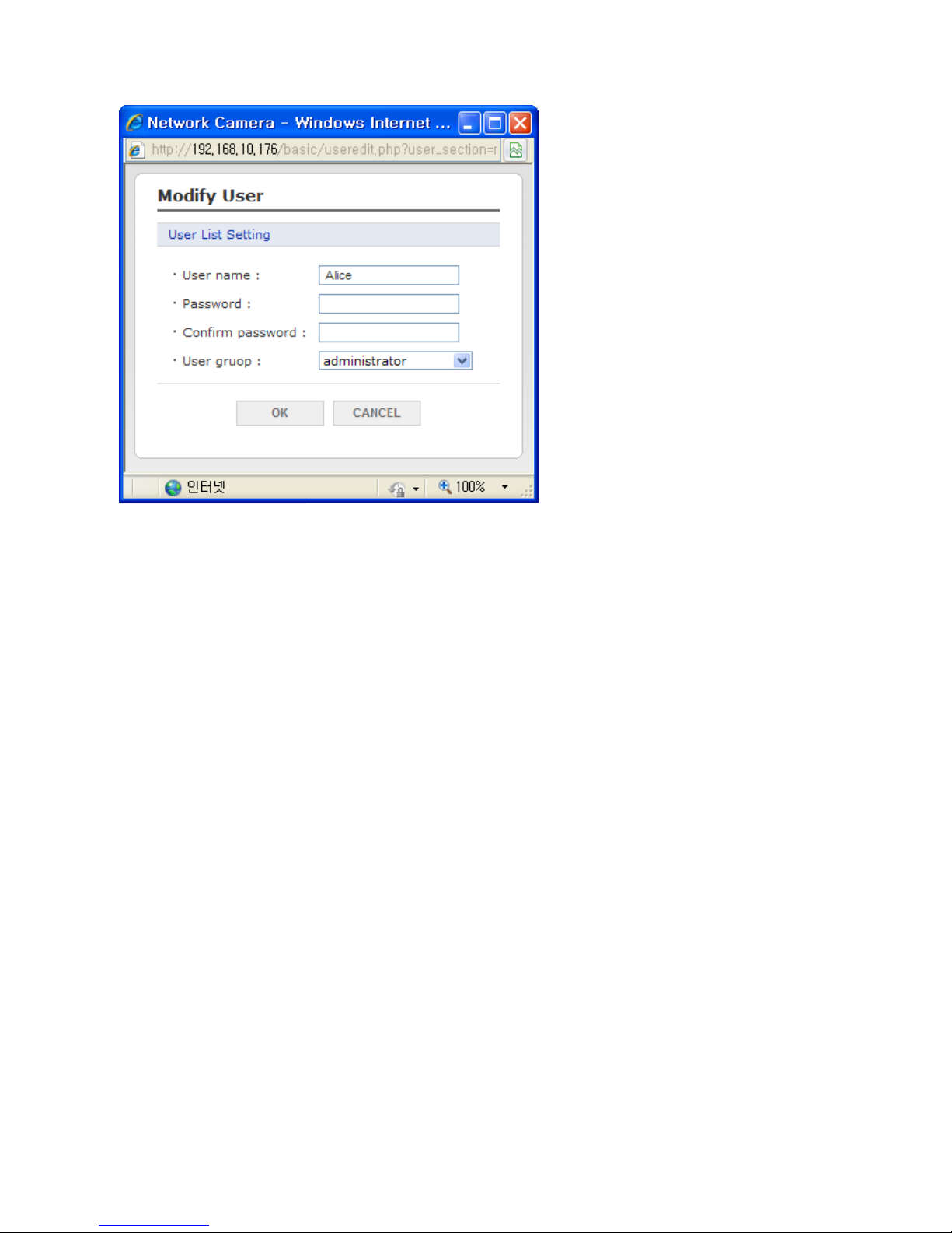
Figure 10. Basic Configuration / Users / Modify User
To modify a user:
1. Select one of the User Name in the User List Setting you want to modify.
2. Click the Modify tab, and then new pop-up window appears.
3. Click in the Password box and type a password (1 to 8 alphanumeric characters). Passwords are
case sensitive.
4. Click in the Confirm password box and retype a password.
5. Click in the User group box and select one of the groups you wish to assign to the user.
6. Click the OK button to save the settings and modify a user.
NOTE
The user name can’t be modified.
To remove a user:
1. Select one of the User Name in the User List Setting you want to remove.
2. Click the Remove tab. A dialog box appears with confirmation message.
3. Click the OK button. The user profile is removed from the User List Setting profile.
NOTE
The admin user name can’t be modified.
- Click the Save button to save the settings, or click the Reset button to clear all of the information
you entered without saving it.
25
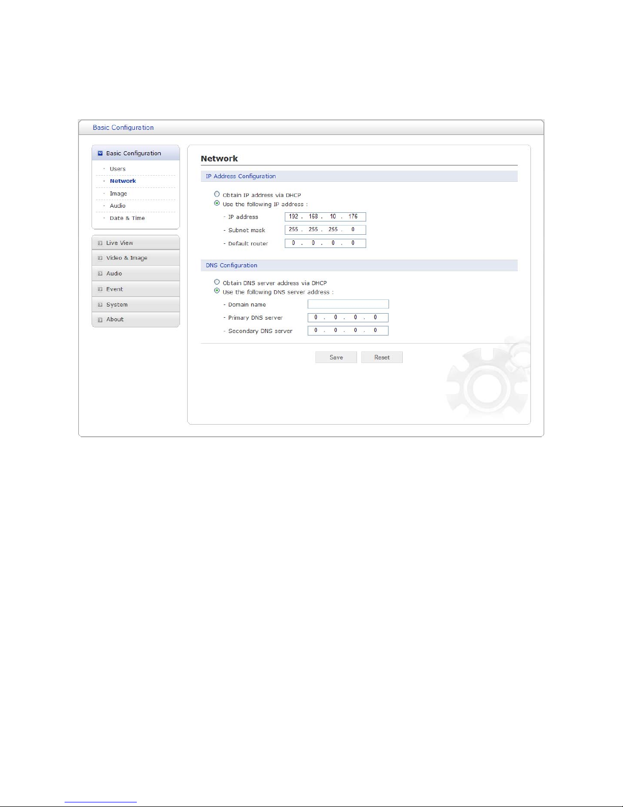
Network
Use the Network tab to manage basic network settings.
Figure 11. Basic Configuration / Network
IP Address Configuration: The DHCP (Dynamic Host Configuration Protocol) server has
a feature that automatically assigns an IP address to the device if there is a device on the network.
Obtain IP address via DHCP: Select the checkbox if you want to assign the IP address from
DHCP server automatically, and then the remaining setting are read-only text.
Use the following IP address: Select the choice box if you want to assign the IP address
manually.
IP address: The address of the camera connected to the network. Specify a unique IP address
for this network camera.
Subnet mask: The address that determines the IP network that the camera is connected to
(relative to its address). Specify the mask for the subnet the network camera is located on.
Default router: The router that accesses other networks. Specify the IP address of the default
router (Gateway) used for connecting devices attached to different networks and network segments.
DNS Configuration: DNS (Domain Name Service) provides the translation of host names to
IP addresses on your network.

26
Obtain DNS server via DHCP: Select the choice box if you want to use the DNS server
settings provided by the DHCP server automatically, and then the remaining setting are read-only
text.
Use the following DNS server address: Select the choice box if you want to use the desired
DNS server manually.
Domain name: Enter the domain to search for the host name used by the network camera.
Primary DNS server: Enter the IP address of the primary DNS server.
Secondary DNS server: Enter the IP address of the secondary DNS server.
- Click the Save button to save the settings, or click the Reset button to clear all of the information
you entered without saving it.
Image
Use the Image tab to adjust the camera image setting value and orientation.
Figure 12. Basic Configuration / Image
Image Appearance: The image appearance allows you to adjust the camera setting
parameters and change the camera orientation. All of parameters are recommended to be
modifying for good image quality suitable for installation place.
27
Brightness: The image brightness can be adjusted in the range 0-20, where a higher value
produces a brighter image. The default setting is 6.
Gamma: Adjusts the details in the light and dark areas of the scene. Gamma can be adjusted in
the range 0.2-1.2, where a lower value expose more detail in the light area of the scene and a
higher value expose more detail in the dark area of the scene. The default setting is 0.5.
Contrast: Controls the gradations between the darkness and lightest portions of the scene. The
contrast can be adjusted in the range 1.0-2.0. The default setting is 1.0.
Saturation: Controls how intense or vivid the colors are in a scene. The saturation can be
adjusted in the range 0-16. The default setting is 8.
Sharpness: Controls the clarity of detail in a scene. The sharpness can be adjusted in the range
0-20. The default setting is 12.
Enable flip image:
Rotate the camera image 180 degrees vertically.
Enable mirror image: Creates a mirror image by rotating the camera image 180 degrees
horizontally.
- Click the Save button to save the settings, or click the Reset button to clear all of the information
you entered without saving it.
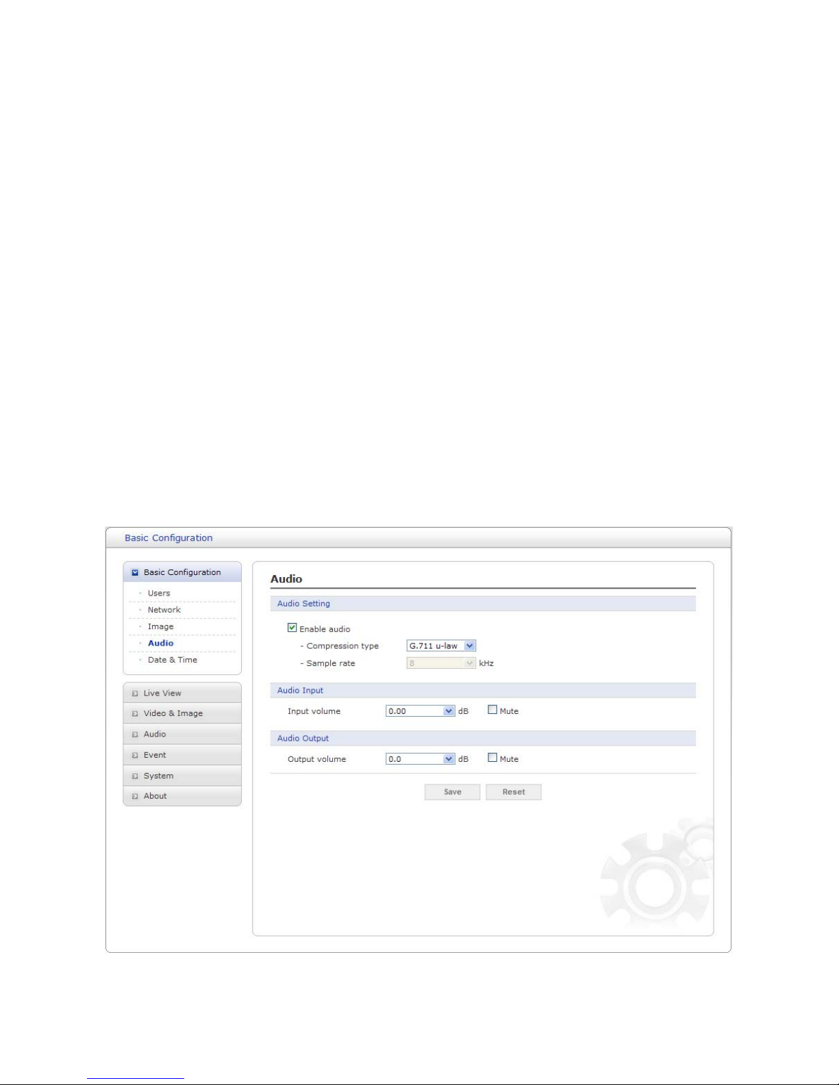
Audio
Use the Audio tab to manage the basic audio settings for the camera.
Figure 13. Basic Configuration / Audio

28
Audio Setting: Click the Enable audio checkbox to enable audio. This page describes how to
configure the basic audio settings for the camera. This camera supports the audio full duplex that
can be transmits and receives audio in both directions at a time.
Compression type: G.711 is the international standard for encoding wired-telephone audio on
64kBit/s channel. It is a PCM (Pulse Code Modulation) scheme operating at 8 kHz sample rate. The
default setting is G.711 µ-law.
Sample rate: Indicates the number of times per second the sound is sampled. The default
setting is 8 kHz.
NOTE
G.711, also known as Pulse Code Modulation (PCM), is a very commonly used waveform codec.
G.711 uses a sampling rate of 8,000 samples per second, with the tolerance on that rate 50 parts
per million (ppm). Non-uniform quantization (logarithmic) with 8 bits is used to represent each
sample, resulting in a 64 kbit/s bit rate. There are two slightly different versions; μ-law, which is
used primarily in North America, and A-law, which is in use in most other countries outside North
America. G.711 μ-law tends to give more resolution to higher range signals while G.711 A-law
provides more quantization levels at lower signal levels.
Audio Input: Adjusts the audio volume especially from the Mike.
Input volume: The Input volume can be adjusted in the range from -21.00 to 21.00 dB. The
default setting is 0 dB. Click the Mute box if you do not want the audio input.
Audio Output: Adjusts the audio volume especially to the Speaker.
Output volume: The Output volume can be adjusted in the range from -18.1 to 6.0 dB. The
default setting is 0 dB. Click the Mute box if you do not want the audio output.
- Click the Save button to save the settings, or click the Reset button to clear all of the information
you entered without saving it.

29
Date & Time
Use the Date and Time tab to set the camera’s date and time values, manually or automatically.
Figure 14. System / Date & Time
Current Server Time: Shows the current date and time.
Date: The default setting is 1970-01-01.
Time: The default setting is 00:00:00.
New Server Time: Select the time zone where your camera is located.
Click the Automatically adjust for daylight saving changes checkbox to automatically update the
time changes caused by daylight saving.
Time zone: The default setting is GMT.
Time mode: The default setting is Set manually.
Synchronize with computer time: Sets the time according to the clock on your computer.
Synchronize with NTP Server: This option will obtain the correct time from an NTP server
every 60 minutes. The NTP server's IP address or host name is specified in the time server.

30
Set manually: Using this option allows you to manually enter the date and time.
Date & Time Format: Select one of the Date and Time format.
Date Format: The default setting is YYYY-MM-DD.
Time Format: The default setting is 24 hours.
- Click the Save button to save the settings, or click the Reset button to clear all of the information
you entered without saving it.
 Loading...