


Quick Installation Guide
1/2,8” Network Dome,
PoE, 1920x1080, ONVIF,
Day&Night, 3.7mm, Indoor
DE
EN
FR
NXD-880F37P

Table of content
Sicherheitshinweise ......................................................................................................3
Komponenten ................................................................................................................3
Layout .............................................................................................................................4
Installation .....................................................................................................................5
Kamerainstallation ............................................................................................................................................................ 5
Anschluss an RJ-45.......................................................................................................................................................6
Schlitz für MicroSD-Speicherkarte ......................................................................................................................... 6
Anschluss der Stromversorgung ............................................................................................................................6
Netzwerkverbindung und IP-Zuweisung .................................................................................................................6
Bedienung ......................................................................................................................8
Zugri über einen Browser ............................................................................................................................................8
Zugri über Internet ........................................................................................................................................................9
Einstellung des Admin-Passworts über eine sichere Verbindung ................................................................... 9
Live View-Seite ................................................................................................................................................................ 10
Allgemeine Steuerelemente ................................................................................................................................. 10
Steuerungs-Werkzeugleiste .................................................................................................................................. 11
Video-Streams ............................................................................................................................................................ 11
Netzwerkkamera-Konguration ............................................................................................................................... 12
Rücksetzen auf die Werkseinstellungen.................................................................................................................13
Weitere Informationen ................................................................................................................................................ 13
2
Sicherheitshinweise
Bitte beachten Sie auch die beiliegenden Sicherheitshinweise und lesen Sie diese Anleitung vor Inbetriebnahme sorgfältig durch.
Wichtige Warnhinweise sind mit einem Achtung-Symbol gekennzeichnet.
i
Wichtige Hinweise sind mit einem Hinweis-Symbol gekennzeichnet.
Komponenten
Das System wird mit den folgenden Komponenten geliefert:
• Minikamera
• Installations-CD
• Installationsanleitung
• Montageset
• Bohrschablone
• Alarmkabel
Hinweis: Prüfen Sie den Packungsinhalt, um sicherzustellen, dass Sie das vollständi-
i
ge System mit allen oben genannten Komponenten erhalten haben.
Hinweis: Adapter für 12V DC ist nicht im Lieferumfang enthalten.
i
DE
3
Layout
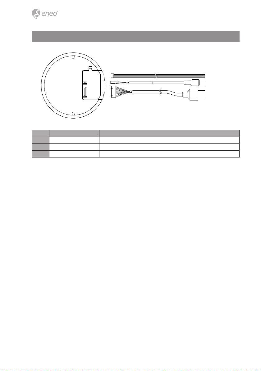
Nr. Name Beschreibung
1 Alarmkabel Gelb: Alarmeingang, schwarz: GND (Masse), blau: Alarmausgang
2 Netzkabel Kabel für Stromversorgung (12V DC)
3 Ethernet-Kabel Kabel für Ethernet (POE)
4
Installation
Kamerainstallation
Entfernen Sie den Inhalt vorsichtig aus der Verpackung und vergewissern Sie sich, dass
während der Lieferung nichts beschädigt wurde.
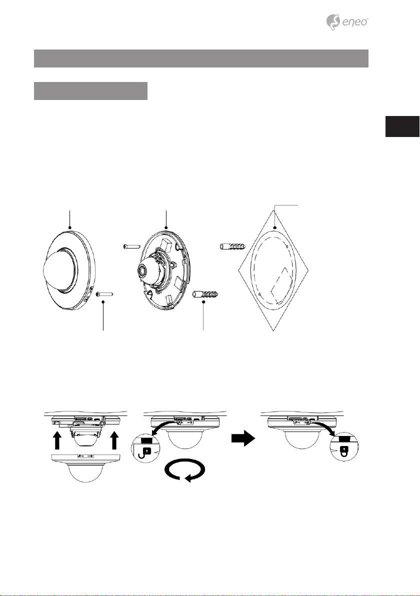
1. Bohren Sie die Löcher für die Schrauben mithilfe der beiliegenden Bohrschablone
in die Decke.
2. Trennen Sie die Kamera-Abdeckung von der Kamera-Basis
3. Befestigen Sie die Kamera an der Decke mit den mitgelieferten Dübeln (2x) und
Schrauben (2x).
Kamera-Abdeckung Dome-Kamera Bohrschablone
Schraube Dübel
DE
4. Bringen Sie die Kamera-Abdeckung an der Dome-Kamera an. Drehen Sie die
Kamera-Abdeckung im Uhrzeigersinn, um die Montage abzuschließen.
Schließen im Uhrzeigersinn
5
Anschluss an RJ-45
Schließen Sie ein Standard-RJ-45-Kabel an den Netzwerkanschluss der Netzwerkkamera
an. Zum Anschluss an einen PC wird im Allgemeinen ein Crossover-Kabel verwendet,
während zum Anschluss an einen Hub ein direktes Kabel (Patch-Kabel) verwendet wird.
Schlitz für MicroSD-Speicherkarte
Legen Sie die SD-Speicherkarte ein.
Anschluss der Stromversorgung
Schließen Sie die 12V DC-Stromversorgung an die Dome-Kamera an.
Netzwerkverbindung und IP-Zuweisung
Mit dem eneo Scan Device Tool können alle eneo Netzwerkkameras in einem lokalen
Netzwerk lokalisiert werden. Das Tool muss nicht mit einem Setup Programm installiert
werden. Die exe-Datei des Programms kann mit einem Doppelklick direkt von der CD
gestartet und benutzt werden.
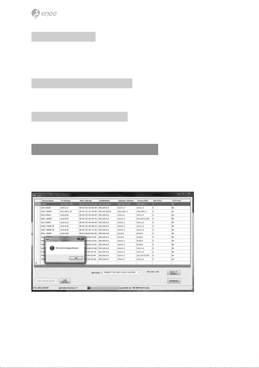
Nach dem Drücken des Buttons „eneo Geräte suchen“ erhalten Sie eine Liste der mit dem
lokalen Netzwerk verbundenen Kameras. Markieren Sie Ihre Kamera in der Liste und
önen Sie ein Kontextmenü durch Klicken der rechten Maustaste.
6
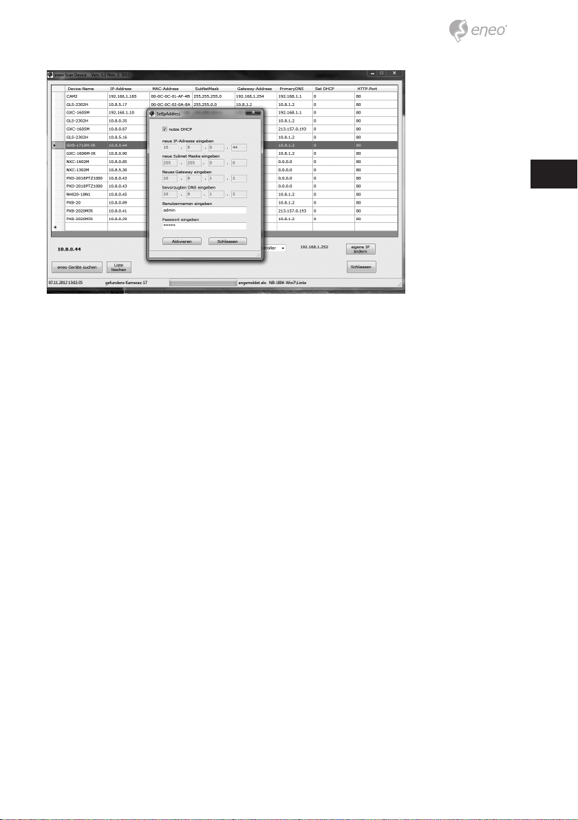
Wählen Sie die „Kamera IP Adresse bearbeiten“ Option um ein Fenster für die Kamera IPEinstellungen zu erhalten. Wenn Sie fertig sind, klicken Sie den „Aktivieren“ Button um die
Kameraeinstellungen zu aktualisieren.
Weitere Informationen nden Sie im eneo Scan Device Tool Quick Start Guide.
DE
7
Bedienung
Die Netzwerkkamera kann mit einem Windows-Betriebssystem und Browsern verwendet werden. Die empfohlenen Browser sind Internet Explorer, Safari, Firefox, Opera und
Google Chrome in Windows.
i
Hinweis: Um das Video-Streaming mit dem Microsoft Internet Explorer zu ermögli-
chen, müssen Sie Ihren Browser so einstellen, dass ActiveX Controls erlaubt werden.
Zugri über einen Browser
1. Starten Sie einen Browser (Internet Explorer).
2. Geben Sie die IP-Adresse oder den Host-Namen der Netzwerkkamera im URL-Feld
(Adresszeile) Ihres Browsers ein.
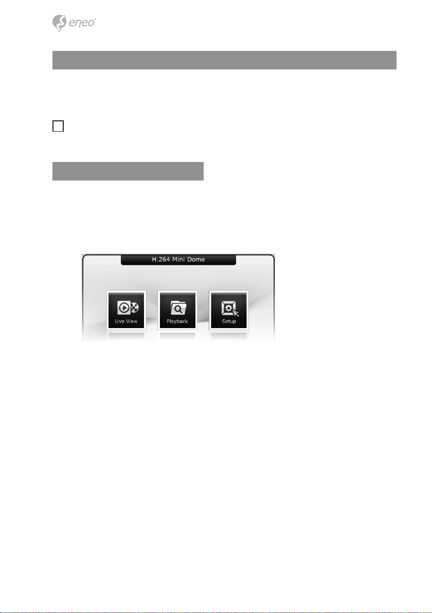
3. Eine Startseite erscheint. Klicken Sie auf Live View (Echtzeitüberwachung) oder
Setup (Konguration), um die entsprechende Webseite aufzurufen.
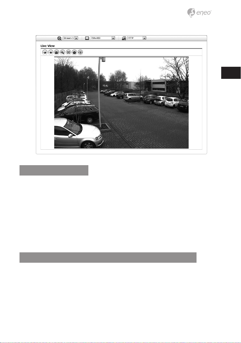
4. Die Live View-Seite der Netzwerkkamera erscheint in Ihrem Browser.
8
Zugri über Internet
Nach dem Einrichten des Zugris über das Internet ist die Netzwerkkamera in Ihrem
lokalen Netzwerk (LAN) verfügbar. Um vom Internet aus auf die Netzwerkkamera zugreifen zu können, müssen Sie Ihren Breitband-Router so kongurieren, dass eingehende
Verbindungen zur Netzwerkkamera zugelassen werden. Schalten Sie dazu die Funktion
„NAT-Traversal“ ein, um den Router automatisch so zu kongurieren, dass der Zugri auf
die Netzwerkkamera möglich ist. Diese Funktion kann unter Konguration > System >
Netzwerk > NAT aktiviert werden.
Weitere Informationen nden Sie unter „3.5.4 System > Netzwerk > NAT“ in der
Betriebsanleitung.
DE
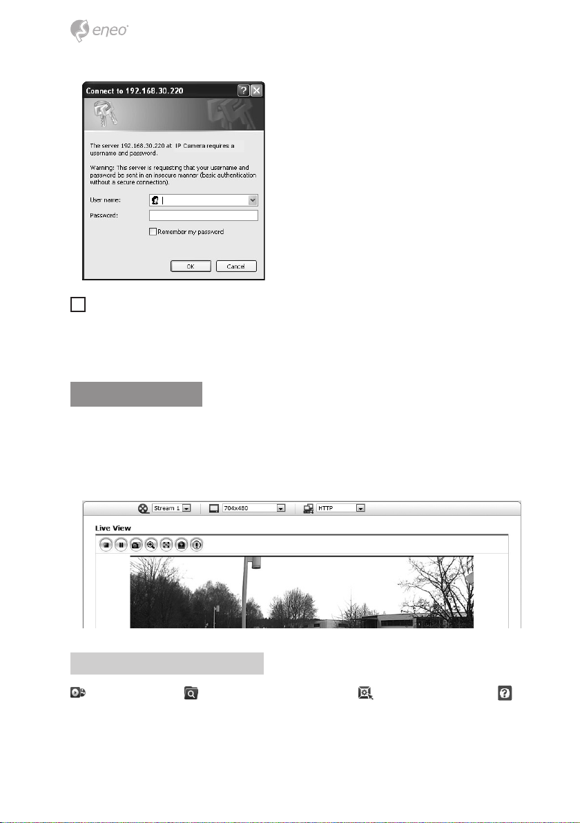
Einstellung des Admin-Passworts über eine sichere Verbindung
Um Zugri auf das Produkt zu erhalten, muss das Kennwort für den Standard-Administrator eingestellt werden. Dies geschieht im Dialog „Admin-Passwort“, der beim ersten
Aufruf der Konguration der Netzwerkkamera angezeigt wird. Geben Sie Ihren AdminNamen und das Kennwort ein, die vom Administrator eingestellt wurden.
9
i
Hinweis: Der Standardname und das Standardkennwort des Administrators
lauten „admin“. Wenn das Kennwort verloren gegangen ist, muss die Netzwerkkamera auf die Werkseinstellungen zurückgesetzt werden. Siehe „3.8 Rücksetzen auf die
Werkseinstellungen“.
Live View-Seite
Die Live View-Seite kann in verschiedenen Anzeigemodi angezeigt werden: 1600 x 1200,
1280 x 1024, 1280 x 720, 800 x 600, 704 x 576, 640 x 480, 352 x 288 und 320 x 240. Benutzer können den am besten geeigneten Modus auswählen. Bitte stellen Sie den Modus gemäß der Leistungsfähigkeit Ihres PCs und dem erforderlichen Überwachungszweck ein.
Allgemeine Steuerelemente
Live View-Seite Suche & Wiedergabe-Seite Kongurationsseite
Hilfeseite
10
. Mit der Video-Dropdown-Liste können Sie einen kongurierten oder einen
vorprogrammierten Video-Stream auf der Live View-Seite anzeigen. Die Stream-Prole
werden unter Setup (Konguration) > Basic Conguration (Grundkonguration) > Video
und Bild konguriert. Weitere Informationen nden Sie unter „3.5.1 Basic Conguration
(Grundkonguration) > Video und Bild“ in der Betriebsanleitung.
In der Dropdown-Liste mit den Auösungen können Sie die für die
Anzeige auf der Live View-Seite am besten geeignete Auösung auswählen.
In der Dropdown-Liste mit den Protokollen können Sie auswählen, welche
Kombination von Protokollen und Methoden verwendet werden soll, die Auswahl hängt
von Ihren Anzeigeanforderungen und den Eigenschaften Ihres Netzwerks ab.
Steuerungs-Werkzeugleiste
Die Werkzeugleiste des Live Viewers ist nur auf der Webbrowser-Seite verfügbar. Die
folgenden Schaltächen werden angezeigt:
Die Stopp-Schaltäche beendet die Wiedergabe des Video-Streams. Durch das
Anklicken wird zwischen Start und Stopp umgeschaltet. Durch Anklicken der StartSchaltäche wird die Verbindung zur Netzwerkkamera aufgebaut bzw. das Abspielen
eines Video-Streams begonnen.
Die Pause-Schaltäche unterbricht die Wiedergabe des Video-Streams.
Mit der Snapshot-Schaltäche wird eine Kopie des aktuellen Bildes erstellt. Der Ort,
an dem die Datei gespeichert wird, kann angegeben werden.
Mit der Digitalzoom-Schaltäche kann das Videobild der Live-Anzeige heran- oder
hinausgezoomt werden.
Mit der Vollbild-Schaltäche wird das Videobild auf die ganze Bildschirmgröße
vergrößert. Andere Fenster sind dann nicht mehr sichtbar. Durch Drücken der 'Esc'-Taste
auf der Computer-Tastatur wird die Vollbildanzeige beendet.
DE
Mit der Schaltäche Manuelle Auslösung wird ein Popup-Fenster aufgerufen, mit
dem das Ereignis manuell gestartet oder gestoppt werden kann.
Video-Streams
Die Netzwerkkamera bietet mehrere Formate für Bilder und Video-Streams. Welchen Typ
Sie verwenden, hängt von Ihren Anforderungen und den Eigenschaften Ihres Netzwerks
ab.
11
Die Live View-Seite der Netzwerkkamera bietet Zugri auf H.264, MPEG-4 und Motion
JPEG Video-Streams und auf die Liste der verfügbaren Video-Streams. Andere Anwendungen und Clients können ebenfalls direkt auf diese Video-Streams/Bilder zugreifen, ohne
die LiveView-Seite aufrufen zu müssen.
Netzwerkkamera-Konguration
In diesem Abschnitt wird die Konguration der Netzwerkkamera beschrieben. Er richtet
sich an Administratoren des Produkts, die uneingeschränkten Zugri auf alle Kongurationswerkzeuge haben sowie an Benutzer, die Zugri auf die Kongurationsseiten für
Grundkonguration, Live View, Video und Bild und die Systemkonguration haben.
Sie können die Netzwerkkamera kongurieren, indem Sie in der rechten oberen Ecke der
Live View-Seite auf Konguration klicken. Klicken Sie auf diese Seite, um die Online-Hilfe
zur Erklärung der Kongurationstools anzuzeigen.
Beim erstmaligen Zugri auf die Netzwerkkamera erscheint der Dialog zur Eingabe des
Admin-Kennworts. Geben Sie Ihren Admin-Namen und das Kennwort ein, die vom Administrator eingestellt wurden.
i
Hinweis: Wenn das Kennwort verloren gegangen ist, muss die Netzwerkkamera auf
die Werkseinstellungen zurückgesetzt werden.
Siehe „Rücksetzen auf die Werkseinstellungen“.
12

Rücksetzen auf die Werkseinstellungen
Um die Netzwerkkamera auf die Werkseinstellungen zurückzusetzen, rufen Sie die Webseite Setup (Konguration) > System > Maintenance (Wartung) auf oder verwenden Sie
die Rücksetztaste an der Netzwerkkamera wie im Folgenden beschrieben:
Verwendung der Rücksetztaste
Folgen Sie den nachstehenden Anweisungen, um die Netzwerkkamera mit der Rücksetztaste auf die Werkseinstellungen zurückzusetzen.
1. Schalten Sie die Netzwerkkamera aus, indem Sie sie vom Netzteil trennen.
2. Drücken und halten Sie die Rücksetztaste mit einer gerade gerichteten Büroklammer, während Sie die Stromversorgung wieder anschließen.
3. Halten Sie die Rücksetztaste mindestens 2 oder mehr Sekunden lang gedrückt.
4. Lassen Sie die Rücksetztaste los.
5. Die Netzwerkkamera wird auf die Werkseinstellungen zurückgesetzt und startet
neu, nachdem das Rücksetzen auf die Werkseinstellungen abgeschlossen ist.
DE
Achtung: Beim Rücksetzen auf die Werkseinstellungen gehen alle Einstellungen verloren,
die Sie vorgenommen haben. (Standard-IP 192.168.30.220)
Weitere Informationen
Bitte halten Sie die Firmware stets aktuell, damit Sie die neuesten Funktionen des Geräts
nutzen können. Die aktuellsten Firmware-Versionen nden Sie auf unserer Website unter
www.eneo-security.com.
Das Benutzerhandbuch und weitere Software-Tools sind auf der eneo Website unter
www.eneo-security.com oder auf der mitgelieferten CD verfügbar.
Informationen zu kompatiblen Video Management Software-Lösungen nden Sie in der
Kategorie Videomanagement unter www.eneo-security.com.
13

Table of content
Notices on safety .........................................................................................................15
Components .................................................................................................................15
Layout ...........................................................................................................................16
Installation ...................................................................................................................17
Camera Installation ........................................................................................................................................................ 17
Connecting to the RJ-45 ......................................................................................................................................... 17
Micro SD memory slot ............................................................................................................................................. 18
Connecting the Power ............................................................................................................................................. 18
Network Connection and IP assignment ............................................................................................................... 18
Operation .....................................................................................................................20
Access from a browser ..................................................................................................................................................20
Access from the internet .............................................................................................................................................. 21
Setting the admin password over a secure connection ................................................................................... 21
Live View Page ................................................................................................................................................................. 22
General controls ........................................................................................................................................................ 22
Control toolbar ........................................................................................................................................................... 23
Video Streams ............................................................................................................................................................. 23
Network Camera Setup ................................................................................................................................................ 24
Resetting to the factory default settings ............................................................................................................... 24
Further information ...................................................................................................................................................... 25
14

Notices on safety
Please also pay attention to the enclosed safety instructions, and carefully read through
this instruction guide before initial operation.
Important points of warning are marked with a caution symbol.
EN
i
Important points of advice are marked with a notice symbol.
Components
The system comes with the following components:
• Mini Camera
• Installation CD
• Installation Guide
• Accessory Kit
• Template sheet
• Alarm Cable
Notice: Check your package to make sure that you received the complete system,
i
including all components shown above.
Notice: Adapter for DC 12V is not supplied.
i
15

Layout
NO Name Description
1 Alarm Cable Yellow : Alarm input, Black : GND, Blue : Alarm output
2 Power Cable Cable for Power source (DC 12V)
3 Ethernet Cable Cable for Ethernet (POE)
16

Installation
Camera Installation
Carefully remove the contents from the box, and verity that nothing was damaged in
shipment.
1. Make screw holes for camera on the ceiling with Template Sheet
2. Disassemble a camera by Camera Cover
3. Fix the camera set using Anchors(2x) and Screws(2x) to the ceiling.
Camera cover Dome camera Template sheet
Screw Anchor
4. Assemble Camera Cover to Dome Camera. Turn Camera Cover clockwise to complete installation.
EN
Lock clockwise
Connecting to the RJ-45
Connect a standard RJ-45 cable to the network port of the network camera. Generally
a cross-over cable is used for directly connection to PC, while a direct cable is used for
connection to a hub.
17

Micro SD memory slot
Insert the SD memory card.
Connecting the Power
Connect the DC 12V power adaptor to the camera.
Network Connection and IP assignment
The eneo scanning device tool is used to locate all eneo network cameras in a local network. The tool does not need to be installed with a setup program. The program exe-le
can be started directly from the CD with a simple double click to use the program.
After pushing the button „Find eneo devices“ you will get a list of cameras connected to
the local network. Highlight your camera in the list and open a context menu with a click
of the right mouse button.
18

Select the „Editing the camera IP address“ option to open a window for setting the cameras IP properties. When you are done click the „Activate“ button to update the camera
settings.
For further information, please refer to the eneo Scan Device Tool Quick Start Guide.
EN
19

Operation
The Network Camera can be used with Windows operating system and browsers. The
recommended browsers are Internet Explorer, Safari, Firefox, Opera and Google Chrome
with Windows.
i
Notice: To view streaming video in Microsoft Internet Explorer, set your browser to
allow ActiveX controls.
Access from a browser
1. Start a browser (Internet Explorer).
2. Enter the IP address or host name of the Network Camera in the Location/Address
eld of your browser.
3. You can see a starting page. Click Live View or Setup to enter web page.
4. The network camera’s Live View page appears in your browser.
20

Access from the internet
Access from the internet once connected, the Network Camera is accessible on your local
network (LAN). To access the network camera from the Internet you must congure your
broadband router to allow incoming data trac to the network camera. To do this, enable
the NAT-traversal feature, which will attempt to automatically congure the router to allow access to the network camera. This is enabled from Setup > System > Network > NAT.
For more information, please see “3.5.4 System>Network>NAT” of User’s Manual.
EN
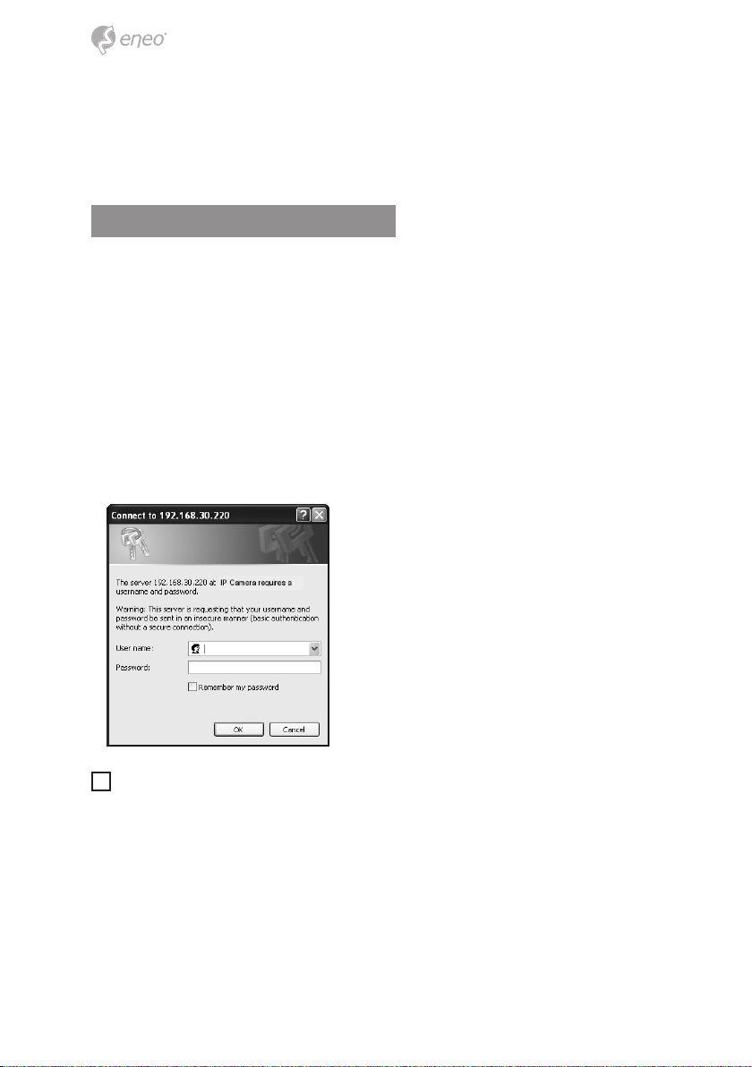
Setting the admin password over a secure connection
To gain access to the product, the password for the default administrator user must be
set. This is done in the “Admin Password” dialog, which is displayed when the network
camera is accessed for the setup at the rst time. Enter your admin name and password,
set by the administrator.
21

i
Notice: The default administrator username is admin and password is admin. If the
password is lost, the Network Camera must be reset to the factory default settings. See
“3.8 Resetting to the Factory Default Settings”.
Live View Page
The live view page comes in several screen modes: 1600x1200, 1280x1024, 1280x720,
800x600, 704x576, 640x480, 352x288 and 320x240. Users are allowed to select the most
suitable one out of those modes. Please, adjust the mode in accordance with your PC
specications and monitoring purposes.
General controls
Live View Page Search & Playback Page Setup Page Help Page
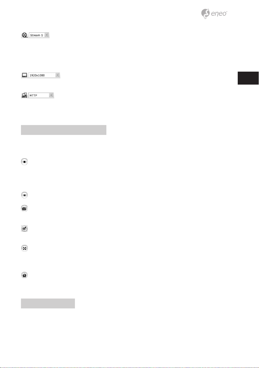
The video drop-down list allows you to select a customized or pre-pro-
grammed video stream on the live view page. Stream proles are congured under Setup
22

> Basic Conguration > Video & Image. For more information, please see “3.5.1 Basic
Conguration > Video & Image” of User’s Manual
The resolution drop-down list allows you to select the most suitable
one out of video resolutions to be displayed on live view page.
The protocol drop-down list allows you to select which combination of
protocols and methods to use depends on your viewing requirements, and on the
properties of your network.
Control toolbar
The live viewer toolbar is available in the web browser page only. It displays the following
buttons:
The Stop button stops the video stream being played. Pressing the key again toggles
the start and stop. The Start button connects to the network camera or start playing a
video stream.
The Pause button pause the video stream being played.
The Snapshot button takes a snapshot of the current image. The location where the
image is saved can be specied.
The digital zoom activates a zoom-in or zoom-out function for video image on the
live screen.
EN
The Full Screen button causes the video image to ll the entire screen area. No other
windows will be visible. Press the ‘Esc’ button on the computer keyboard to cancel full
screen view.
The Manual Trigger button activates a pop-up window to manually start or stop the
event.
Video Streams
The network camera provides several images and video stream formats. Your requirements and the properties of your network will determine the type you use.
The Live View page in network camera provides access to H.264, MPEG-4 and Motion
JPEG video streams, and to the list of available video streams. Other applications and
clients can also access these video streams/images directly, without going via the Live
View page.
23

Network Camera Setup
This section describes how to congure the network camera, and is intended for product
Administrators, who have unrestricted access to all the Setup tools; and Operators, who
have access to the settings for Basic, Live View, Video & Image and System Conguration.
You can congure the network camera by clicking Setup in the top right-hand corner of
the Live View page. Click on this page to access the online help that explains the setup
tools
When accessing the Network Camera for the rst time, the “Admin Password” dialog
appears. Enter your admin name and password, set by the administrator.
i
Notice: If the password is lost, the Network Camera must be reset to the factory
default settings.
See “Resetting to the Factory Default Settings”.
Resetting to the factory default settings
To reset the Network Camera to the original factory settings, go to the Setup>System>
Maintenance web page or use the Reset button on the network camera, as described
below:
24

Using the Reset Button
Follow the instructions below to reset the Network Camera to the factory default settings
using the Reset button.
1. Switch o the Network Camera by disconnecting the power adapter.
2. Press and hold the Reset button with a straightened paperclip while reconnecting
the power.
3. Keep the Reset button pressed during about 2 seconds.
4. Release the Reset button.
5. The network camera resets to factory defaults and restarts after completing the
factory reset.
Caution: When performing a Factory Reset, you will lose any settings you have saved.
(Default IP 192.168.30.220)
Further information
Make sure to always upgrade to the latest rmware version available from the eneo website at www.eneo-security.com to receive the latest functionality for your product.
The manual, and other software tools are available on the eneo website at www.eneo-security.com or on the included CD.
EN
Information on compatible video management software solutions can be found in the
category Videomanagement at www.eneo-security.com.
25

Table of content
Remarques à propos de la sécurité ...........................................................................27
Composants .................................................................................................................27
Agencement .................................................................................................................28
Installation ...................................................................................................................29
Installation de la caméra .............................................................................................................................................. 29
Connexion au RJ-45 .................................................................................................................................................. 29
Logement Carte Micro SD ...................................................................................................................................... 30
Connexion de l´alimentation ................................................................................................................................ 30
Connexion au réseau et attribution d’une adresse IP ....................................................................................... 30
Fonctionnement ..........................................................................................................32
Accès à partir d’un navigateur ................................................................................................................................... 32
Accès à partir de l’internet .......................................................................................................................................... 33
Dénition du mot de passe d'administrateur à travers une connexion sécurisée ................................. 33
Page Live View (achage en direct) ........................................................................................................................ 34
Commandes générales ........................................................................................................................................... 34
Barre d’outils ............................................................................................................................................................... 35
Streaming vidéo ........................................................................................................................................................ 35
Conguration de la caméra réseau .......................................................................................................................... 36
Réinitialisation aux paramètres par défaut d'usine ........................................................................................... 36
Complément d'information ........................................................................................................................................ 37
26

Remarques à propos de la sécurité
Respectez les consignes de sécurité ci-après et lisez attentivement cette notice avant
toute utilisation.
Les mises en garde importantes sont précédées d´un symbole
d´avertissement.
FR
i
Les points importants sont précédés d´un symbole de notice.
Composants
Le système est fourni avec les composants suivants:
• Mini-caméra
• CD d'installation
• Guide d'installation
• Kit d'accessoires
• Gabarit de montage
• Câble pour alarme
Remarque : Veuillez contrôler votre package an de vous assurer que vous avez reçu
i
le système intégral, y compris tous les composants montrés plus haut.
Remarque: L'adaptateur CC12V n'est pas fourni.
i
27

Agencement
No Nom Description
1 Câble pour alarme Jaune Entrée alarme, noir : GND, bleu :sortie alarme
2 Câble d'alimentation Câble d'alimentation (12V CC)
3 Câble Ethernet Câble pour Ethernet (PoE)
28

Installation
Installation de la caméra
Sortez soigneusement le contenu de la boîte et vériez si rien n'a été endommagé durant
le transport.
1. Percez les trous au plafond au moyen des gabarits de montage
2. Désassemblez la caméra en commençant par le cache
3. Fixez l'ensemble de la caméra au plafond à l'aide des chevilles (2x) et vis(2x).
Cache de la caméra Caméra dôme Gabarit de montage
Vis Cheville
4. Montez le cache de la caméra sur la caméra dôme. Tournez le cache de la caméra
dans le sens des aiguilles d'une montre pour terminer l'installation.
FR
Verrouillage dans le sens des
aiguilles de la montre
Connexion au RJ-45
Branchez un câble RJ-45 standard au port réseau de la caméra réseau. En général, un
câble croisé est utilisé pour une connexion directe à un PC alors qu’un câble direct est
employé pour se connecter à un concentrateur.
29

Logement Carte Micro SD
Insérez la carte microSD.
Connexion de l´alimentation
Connectez l’adaptateur de courant 12 V CC à la caméra.
Connexion au réseau et attribution d’une adresse IP
L´outil de balayage d´eneo est utilisé pour localiser toutes les caméras réseau dans le
réseau local. Un programme d´installation n´est pas nécessaire pour installer cet outil. Le
programme exe.le peut être démarré directement du CD avec un double clic.
Après avoir appuyé sur le bouton « Find eneo devices » (trouver le dispositif eneo), vous
pourrez prendre connaissance de la liste des caméras connectées au réseau local. Sélectionner votre caméra dans la liste et ouvrir le menu contextuel en cliquant avec le bouton
droit de la souris.
30

Sélectionner l´option « Editing the camera IP address » (taper l´adresse de la caméra IP)
pour ouvrir une fenêtre et rentrer l´adresse IP. Quand vous avez ni, cliquer sur « activate»
(activer) pour actualiser les paramètres de la caméra.
Pour plus d´informations, merci de vous référer au Scan Device Tool Quick Start Guide
(guide d´installation rapide du dispositif de balayage).
FR
31

Fonctionnement
La caméra de réseau peut être utilisée avec un système d'exploitation Windows et la
plupart des navigateurs standards. Les navigateurs recommandés sont Internet Explorer,
Safari, Firefox, Opera et Google Chrome sous Windows.
i
Remarque : pour consulter la vidéo en streaming dans Microsoft Internet Explorer,
congurez votre navigateur de manière à accepter les contrôles ActiveX.
Accès à partir d’un navigateur
1. Lancez un navigateur (Internet Explorer).
2. Saisissez une adresse IP ou un nom d’hôte pour la caméra de réseau dans le
champ d'adresse de votre navigateur.
3. La page d'accueil s'ouvre. Cliquez sur Live View ou Setup pour accéder à la page
web.
4. La page Live View de la caméra réseau s'ouvre dans votre navigateur.
32

Accès à partir de l’internet
Accès à partir de l’internet. Une fois connectée, la caméra rédeau est accessible depuis
votre réseau local (LAN). Pour accéder à la caméra réseau depuis l'Internet, vous devez
congurer votre routeur à large bande an d’autoriser le trac de données entrantes
vers la caméra réseau. À cette n, activez la fonction NAT-traversal, laquelle essaiera de
congurer automatiquement le routeur pour permettre un accès à la caméra réseau. Pour
l’activation, le chemin à suivre est: Setup>System>Network>NAT.
Pour plus d'informations, référez-vous à « 3.5.4 Système > Réseau > NAT » du Manuel de
l'utilisateur.
Dénition du mot de passe d'administrateur à travers une connexion
FR
sécurisée
Pour accéder au produit, il est nécessaire de congurer le mot de passe de l'administrateur par défaut. Pour ce faire, il convient d'utiliser la boîte de dialogue «Admin
Password», qui apparaît lors de la première connexion à la caméra réseau à des ns de
conguration. Saisissez votre nom et mot de passe utilisateur, déni par l’administrateur.
33

i
Remarque : Le nom et le mot de passe d'administrateur par défaut sont «admin».
En cas de perte du mot de passe, la caméra réseau doit être réinitialisée aux paramètres
d'usine. Voir «3.8 Réinitialisation aux paramètrespar défaut d'usine».
Page Live View (achage en direct)
La page de l'achage en direct propose plusieurs modes de l'écran: 1600x1200,
1280x1024, 1280x720, 800x600, 704x576, 640x480, 352x288 et 320x240. L'utilisateur peut
sélectionner le mode qui lui convient le mieux. Veuillez ajuster le mode en fonction des
spécications de votre PC et de vos objectifs en matière de surveillance.
Commandes générales
Live View Page (page d'achage en direct) Playback Page (page de lecture)
Setup Page (page de conguration) Help Page (page d'aide)
La liste déroulante vidéo vous permet de sélectionner un ux vidéo
personnalisé ou préprogrammé sur la page d'achage en direct. Les prols de ux sont
34

congurés dans Setup > Basic Conguration > Video & Image. Pour de plus amples
informations, veuillez vous référer à « 3.5.1 Conguration de base> Vidéo & Image » du
Manuel de l'utilisateur.
La liste déroulante de la résolution vous permet de sélectionner la
résolution vidéo la plus adéquate à acher sur la page de l'achage en direct.
La liste déroulante des protocoles vous permet de sélectionner la
combinaison de protocoles et méthodes à utiliser. Elle est fonction de vos exigences
d'achage et des propriétés de votre réseau.
Barre d’outils
La barre d’outils Live Viewer apparaît uniquement sur la page du navigateur web. Elle
ache les boutons suivants : Le bouton Stop arrête le ux vidéo en cours de lecture.
Le bouton Stop arrête le ux vidéo en cours de lecture. Réappuyer sur la touche
permet de basculer entre start et stop. Le bouton Start lance une connexion à la caméra
réseau ou la lecture d’un ux vidéo.
Le bouton Pause marque une pause dans la lecture du ux vidéo.
Le bouton Snapshot prend un instantané de l’image achée à l’écran. L'emplacement
où l'image est sauvegardée peut être spécié.
Le bouton Digital Zoom déclenche un zoom vers l’avant ou l’arrière à partir de
l'image achée sur l’écran.
FR
Moyennant le bouton Full Screen, l'image vidéo est achée sur la totalité de l'écran.
Aucune autre fenêtre ne sera alors visible. Appuyez sur le bouton 'Esc' du clavier de
l’ordinateur an d’annuler la vue plein écran.
Le bouton Manual Trigger ache une fenêtre contextuelle permettant de lancer ou
d’arrêter manuellement un événement.
Streaming vidéo
La caméra réseau ore plusieurs formats d’image et de ux vidéo. Vos exigences et les
propriétés de votre réseau détermineront le format que vous utilisez.
<La page d'achage en direct de la caméra réseau permet d’accéder aux ux vidéo
H.264, MPEG-4 et Motion JPEG, ainsi qu’à la liste des ux vidéo disponibles. D’autres
35

applications et clients peuvent également accéder directement à ces ux/images vidéo
via la page Live View.
Conguration de la caméra réseau
La présente rubrique précise comment congurer la caméra réseau et est reservée aux
administrateurs du produit qui jouissent d'un accès illimité à tous les outils de conguration ainsi qu'aux opérateurs qui ont accès aux paramètres Basic, Live View, Video & Image,
Audio, Event et System Conguration.
Vous pouvez congurer la caméra réseau en cliquant sur « Setup » dans le coin supérieur
droit de la page d'achage en direct. Cliquez sur cette page pour accéder à l'aide en
ligne où les utilitaires de conguration sont expliqués.
Lors de la première connexion de la caméra réseau, la boîte de dialogue «Admin
Password» (mot de passe « admin » apparaît) s'ouvre. Saisissez votre nom et mot de
passe utilisateur, déni par l’administrateur.
i
Remarque : En cas de perte du mot de passe, la caméra réseau doit être réinitialisée
aux paramètres s'usine.
Voir «Réinitialisation aux paramètrespar défaut d'usine».
Réinitialisation aux paramètres par défaut d'usine
Pour réinitialiser la caméra réseau aux paramètres d'usine, suivez la page Internet Setup>System> Maintenance ou utilisez le bouton de réinitialisation sur la caméra réseau,
comme décrit ci-dessous :
36

Utilisation du bouton Reset
Veuillez suivre les instructions ci-dessous pour réinitialiser la caméra réseau aux paramètres d'usine à l'aide du bouton Reset.
1. Éteignez la caméra réseau en débranchant l'adaptateur de courant.
2. Appuyez et maintenez le bouton de contrôle enfoncé avec un trombone redressé
tout en remettant le courant.
3. Maintenez le bouton de réinitialisation enfoncé pendant 2 secondes environ.
4. Relâchez le bouton de réinitialisation Reset.
5. La caméra réseau est réinitialisée aux paramètres d’usine et redémarre une fois
ladite réinitialisation terminée.
Attention : Lorsque vous utilisez la fonction Factory Reset (réinitialisation aux paramètres
d’usine), vous perdez tous les paramètres que vous avez sauvegardés. (Le paramètre
d’usine par défaut est « 192.168.30.220 »)
Complément d'information
Assurez-vous de toujours être à jour grâce à la dernière version de rmware disponible
depuis le site d'eneo sous www.eneo-security.com pour recevoir les dernières fonctionnalités de votre produit.
Le manuel utilisateur et d’autres outils logiciels sont disponibles sur le site web eneo
www.eneo-security.com ou sur le CD joint.
Des informations concernant les solutions logicielles de gestion vidéo compatibles sont
disponibles dans la catégorie Videomanagement (gestion des vidéos) sur www.eneo-security.com.
FR
37

38

FR
39

eneo® is a registered trademark of
Videor E. Hartig GmbH
Exclusive distribution through specialised
trade channels only.
Videor E. Hartig GmbH
Carl-Zeiss-Straße 8
63322 Rödermark/Germany
Tel. +49 (0) 6074 / 888-0
Fax +49 (0) 6074 / 888-100
www.videor.com
www.eneo-security.com
Technical changes reserved
© Copyright by Videor E. Hartig GmbH
Version 03/2015
 Loading...