

Eneo NXD-1502M Quick Installation Manual
Please read this manual thoroughly before use and keep it handy for future reference.
NXD-1502M
Full HD NETWORK CAMERA
GB
NXD-1502M, Quick Installation Guide
1. Description
This manual applies to the NXD-1502M network camera.
The Network Camera supports the network service for a sensor image with progressive scan, which
can be monitored on a real-time screen regardless of distances and locations. By using its dedicated
program, many users are able to have an access to the Network Camera at once or a single user can
monitor various network cameras at the same time. It also enables users to play, store and retrieve a
monitoring image by using a PC. All the settings and real-time monitoring screens are also provided
through an access to the web.
The Network Camera is fully featured for security surveillance and remote monitoring needs. It is
based on the DSP compression chip, and makes it available on the network as real-time, full frame
rate Motion JPEG and H.264 (or MPEG-4) video streams.
The alarm input and alarm output can be used to connect various third party devices, such as, door
sensors and alarm bells.
• Installation Steps
Follow these steps to install the Network Transmitter on your local network (LAN):
1. Check the package contents against the list below.
2. Connect the Network Camera. See page 3.
3. Set an IP address. See page 4.
4. Set the password. See page 6.
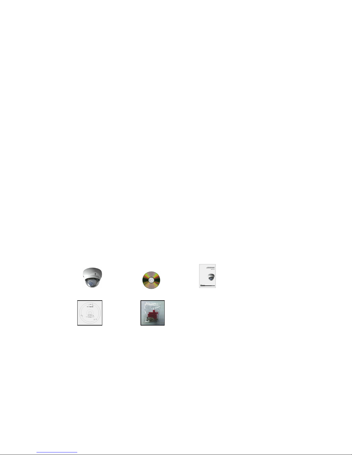
• Package Component
The system comes with the following components:
Network Camera unit Installation CD Installation Guide
Template Sheet Accessory Kit
• Contents in the installation CD
1. The Network Camera User’s Manual
2. The NautilusClient16 User’s Manual
3. The Nautilus Server User’s Manual
4. The NautilusClient16 Installation software
5. The Nautilus Server Installation software
Note: Check your package to make sure that you received the complete system, including all
components shown above.

NXD-1502M, Quick Installation Guide
2
2. Installation
For the operation of the Network Camera, it is necessary to connect a network cable for data
transmission, power connection from supplied power adapter. Depending on operation methods, it is
possible to connect an alarm cable additionally. For its fixation on different locations, please consult
with an installer.
2.1 Over View
•
Top View
NO Name Description
1
Lens
Allows wide area to be
monitored
2
Extension
Cable
26pin camera extension
cable
•
Extension Cable
NO
Wire Color Description
1
Red: AC24V/DC12V
White: AC24V/GND
Main Power, 2pin terminal, DC12V/AC24V 330mA(4.0W)
2
Green: AC24V/DC12V
Black: AC24V/GND
Heater Power, 2pin terminal, max. 10Watt @ DC12V,
max. 20Watt @ AC24V
3
Pink: Alarm In
Yellowish Green: GND
Yellow: AD Key
Brown: GND
Light Blue: Alarm Out
Gray: GND
Alarm Input, AD Key Input, Alarm Output:
6pin terminal.
4
Black
Ethernet,
RJ-45 port compatible with 10/100Mbps PoE.
Modular Jack
5
Black
Video Composite Output, BNC Jack
6 Gray Audio line output, Stereo Jack
7
Black
Audio line input, Stereo Jack
NXD-1502M, Quick Installation Guide
3
2.2 Connection
• Connecting to the RJ-45
Connect a standard RJ-45 cable to the network port of the network camera. Generally a
cross-over cable is used for directly connection to PC, while a direct cable is used for connection
to a hub.
• Connecting Alarms
AI(Alarm In) :
You can use external devices to signal the network camera to react on events. Mechanical or
electrical switches can be wired to the AI (Alarm In) and G (Ground) connectors.
G(Ground) :
Connect the ground side of the alarm input and/or alarm output to the G (Ground) connector.
Alarm Out :
The network camera can activate external devices such as buzzers or lights. Connect the device
to the AO (Alarm Out) and G (Ground) connectors.
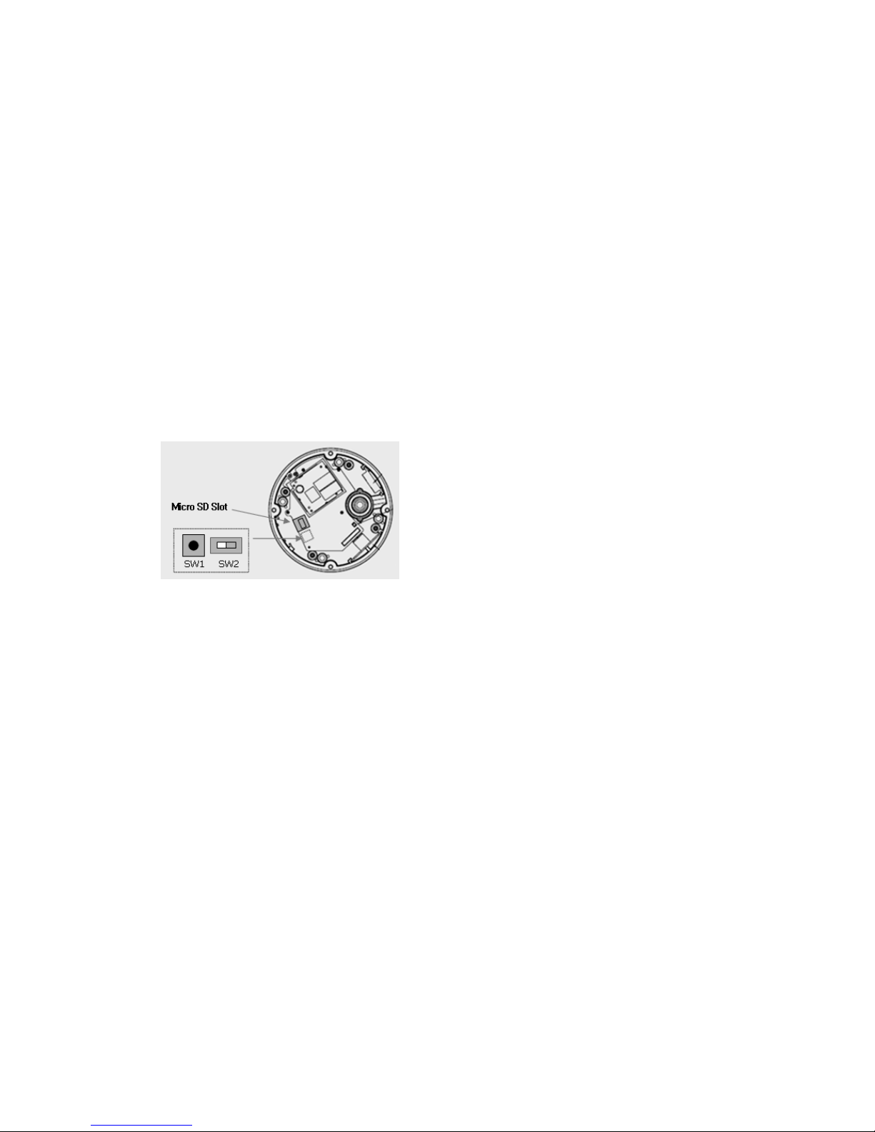
• Connecting Video Output
Video Output is used for an easy zoom and focus
control when installing lens. Set Video Switch (SW2 on
the board) to On position to output the video signal.
Video Output is restricted to VGA(640x480) resolution.
Caution: After lens installation, you must set Video Switch to Off position to provide the best
performance of the Network Camera.
• Connecting the Power
Connect the power of DC12V or AC24V 330mA for the network camera. Connect the positive(+)
pole to the ‘+’ position and the negative(-) pole to the ‘-‘ position for the DC power.
2.3 Network Connection and IP assignment
The Network Camera supports the operation through the network. When a camera is first connected
to the network it has no IP address. So, it is necessary to allocate an IP address to the device with the
“Smart Manager” utility on the CD.
1. Connect the Network Camera / device to the network and power up.
2. Start SmartManager utility ( All programs > NautilusClient16 > SmartManager), the main window
will be displayed, after a short while any network devices connected to the network will be
displayed in the list.
 Loading...