

Eneo NXC-1502M Quick Installation Manual
NXC-1502M
Full HD NETWORK CAMERA
Please read this manual thoroughly before use and keep it handy for future reference.
GB
NXC-1502M, Quick Installation Guide
1. Description
This manual applies to the NXC-1502M network camera.
The Network Camera supports the network service for a sensor image with progressive scan, which
can be monitored on a real-time screen regardless of distances and locations. By using its dedicated
program, many users are able to have an access to the Network Camera at once or a single user can
monitor various network cameras at the same time. It also enables users to play, store and retrieve a
monitoring image by using a PC. All the settings and real-time monitoring screens are also provided
through an access to the web.
The Network Camera is fully featured for security surveillance and remote monitoring needs. It is
based on the DSP compression chip, and makes it available on the network as real-time, full frame
rate Motion JPEG and H.264 (or MPEG-4) video streams.
The alarm input and alarm output can be used to connect various third party devices, such as, door
sensors and alarm bells.
• Installation Steps
Follow these steps to install the Network Transmitter on your local network (LAN):
1. Check the package contents against the list below.
2. Connect the Network Camera. See page 3.
3. Set an IP address. See page 4.
4. Set the password. See page 5.
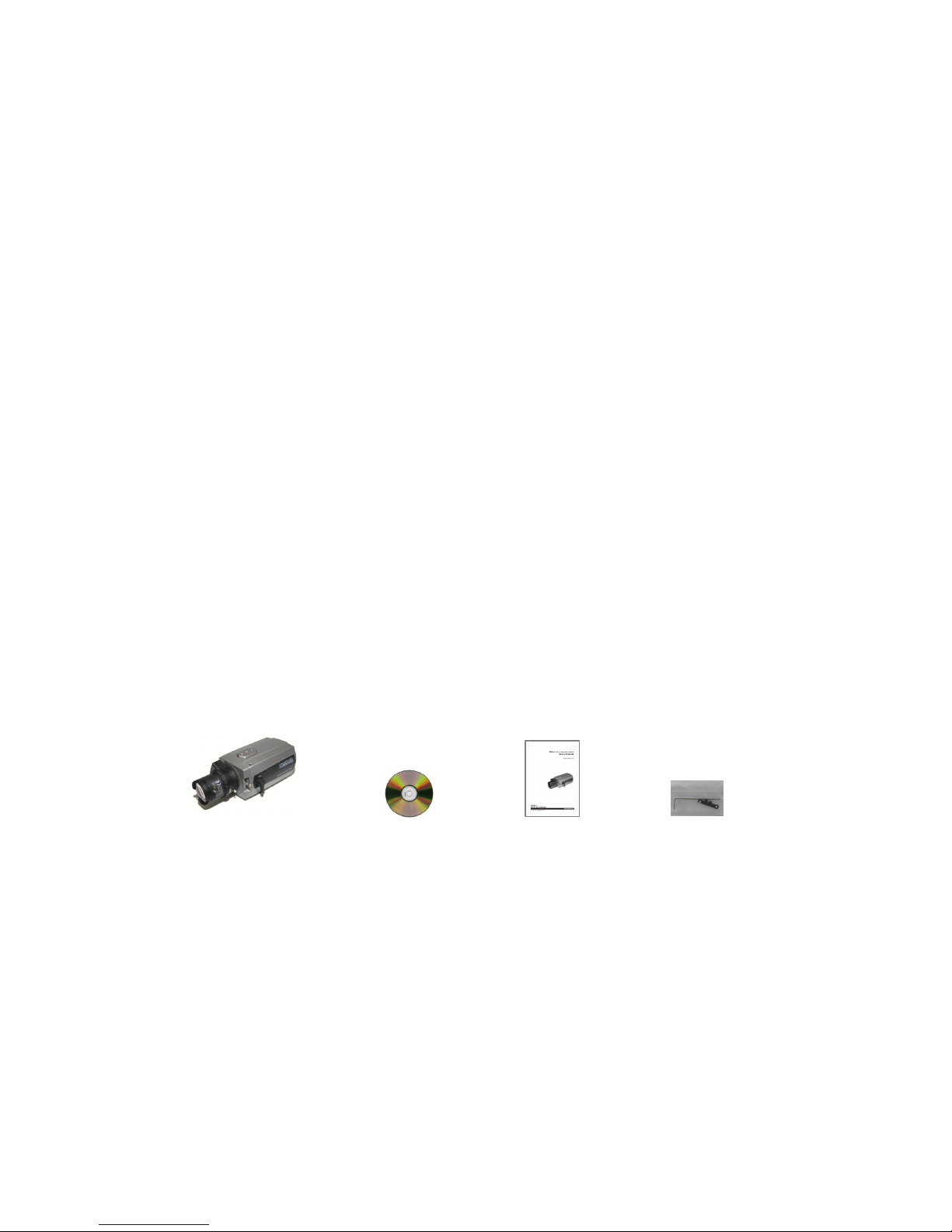
• Package Component
The system comes with the following components:
Network Camera unit Installation CD Installation Guide Accessory Kit
• Contents in the installation CD
1. The Network Camera User’s Manual
2. The NautilusClient16 User’s Manual
3. The Nautilus Server User’s Manual
4. The NautilusClient16 Installation software
5. The Nautilus Server Installation software
Note: Check your package to make sure that you received the complete system, including all
components shown above.
NXC-1502M, Quick Installation Guide
2
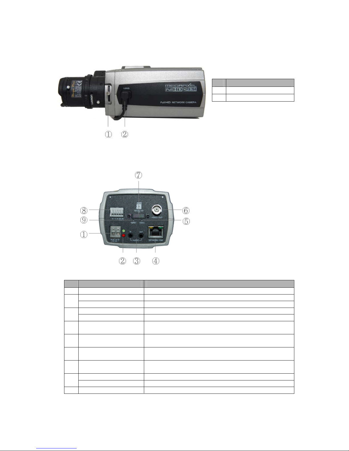
• Front View
NO Function
1 Focus adjusting fixing screw
2 Auto IRIS lens connector
• Rear View
NO Function Description
1 Power Adaptor Terminal Main Power, 2pin terminal, DC12V/AC24V 330mA(4.0W)
2
Power Indicator(Green) Indicates power input.
Status Indicator(Red) Indicates camera status.
3
Audio Input Audio Input Stereo Jac
k
Audio Output Audio Output Stereo Jac
k
4 Network Connector (PoE)
RJ-45 port compatible with 10/100Mbps, which have a PoE
function.
5 Video Switch
Selects Video On/Off.
Set to On to output a video signal.
The video image is shown only for 30 seconds.
6 Video Output
Connects the video output. This BNC connector provides a
1.0Vp-p/75 ohms composite video signal.
7 Micro SD Card Slot
Card Slot for Micro SD. Open the protection cover with a
supported tool to insert Micro SD card.
8
3pin Terminal IO Connects alarm In/Out.
2pin RS485 Terminal Connects PT device.
9 Reset Button Executes the factory default.

NXC-1502M, Quick Installation Guide
3
• LED Indicators
LED Color Indication
Network
Green
Steady for connection to a 100 Mbit/s network.
Flashes for
network activity.
Amber
Steady for connection to 10 Mbit/s network.
Flashes for
network activity.
Unlit No network connection.
Status
Red
Steady red for failed upgrade or booting.
Power
Green
Steady green for normal operation or booting.
Flashes green during firmware upgrade.
Note: Steady green and red during booting. Flash green and red during factory default.
2. Installation
2.1 Connection
• Connecting to the RJ-45
Connect a standard RJ-45 cable to the network port of the network camera. Generally a
cross-over cable is used for directly connection to PC, while a direct cable is used for connection
to a hub.
• Connecting Alarms
AI(Alarm In) :
You can use external devices to signal the network camera to react on events. Mechanical or
electrical switches can be wired to the AI (Alarm In) and G (Ground) connectors.
G(Ground) :
Connect the ground side of the alarm input and/or alarm output to the G (Ground) connector.
Alarm Out :
The network camera can activate external devices such as buzzers or lights. Connect the device
to the AO (Alarm Out) and G (Ground) connectors.
• Connecting Video Output
Video Output is used for an easy zoom and focus control when installing lens. Set Video Switch to
On position to output the video signal. Video Output is restricted to VGA(640x480) resolution.
Caution: After lens installation, you must set Video Switch to Off position to provide the best
performance of the Network Camera.
• Connecting the Power
Connect the power of DC12V or AC24V 330mA for the network camera. Connect the positive(+)
pole to the ‘+’ position and the negative(-) pole to the ‘-‘ position for the DC power.
 Loading...