

Eneo MSR-24N080004A, MSR-24N040004A Quick Installation Manual

EN
Quick Installation Guide
Multisignal HD Video Recorder, HD-TVI, AHD, 960H, 2xSATA,
HDMI
MSR-24N040004A
MSR-24N080004A
DE
FR
IT

2
Contents
Components...................................................................................................................5
Description ....................................................................................................................6
Front.......................................................................................................................................................................................6
Rear .......................................................................................................................................................................................6
Installation .....................................................................................................................8
Installation ...........................................................................................................................................................................8
Installing HDDs .................................................................................................................................................................8
Starting System .................................................................................................................................................................9
Quick Setup ..................................................................................................................................................................... 10
Account ........................................................................................................................................................................10
System .........................................................................................................................................................................10
Network ........................................................................................................................................................................11
Time/Date ................................................................................................................................................................... 12
Record ........................................................................................................................................................................... 13
Live Screen Conguration ......................................................................................... 14
Icons in Live screen .......................................................................................................................................................14
Live Launcher menu .................................................................................................................................................... 16
Quick menu ......................................................................................................................................................................17
Setup menu ................................................................................................................ 18
Further information .................................................................................................. 19

3
EN
Safety instructions
General safety instructions
• Before switching on and operating the system, rst read this safety advice and the operating instructions.
• Keep the operating instructions in a safe place for later use.
• Installation, commissioning and maintenance of the system may only be carried out by authorised
individuals and in accordance with the installation instructions - ensuring that all applicable standards and
guidelines are followed.
• Protect the devices from water penetration and humidity, since these can cause lasting damage.
• Should moisture nevertheless enter the system, under no circumstance switch on the devices under these
conditions, instead send them for examination to an authorised specialist workshop.
• The system must never be used outside of the technical specications, since this can destroy it.
• The device must be protected from excesses of heat, dust, humidity and vibration.
• When separating the system from the voltage supply, only ever use the plug to pull out the cable. Never
pull directly on the cable itself.
• Lay the connecting cables carefully and check that they are not mechanically stressed, kinked or damaged
and that no humidity can penetrate into them.
• In the event of a malfunction, please inform your supplier.
• Maintenance and repairs may only be carried out by authorised specialist personnel.
• The system must be isolated from the power supply before opening the housing.
• The device may only be opened by qualied service personnel. Unauthorised access invalidates any
warranty claim.
• Connection cables should always be exchanged through Videor E. Hartig GmbH.
• Use only original spare parts and accessories from Videor E. Hartig GmbH.
• The housing should only be cleaned using a mild domestic cleaning agent. Never use solvents or petrol as
these can permanently damage the surface.
• During installation, it is essential to ensure that the seals provided are correctly installed and that they are
not displaced during installation. Damaged seals must not be installed and will invalidate any warranty.
• The installer is responsible for the maintenance of the enclosure as per the technical data, e.g. by sealing
the cable outlets with silicone.
• Wire end ferrules should be used when shortening the exible connection cables.
• The devices may only be operated in the temperature range indicated in the data sheet and within the
dened air humidity range.
Product - Specic Safety Instructions
• The camera may never be pointed directly at the Sun with the aperture open (this will destroy the sensor).
• It is unavoidable that during manufacture and to a certain extent during later use, humidity will be present
in the ambient air within the device’s housing. In the event of large temperature uctuations, this humidity
may condense inside the housing.
• To avoid this condensation inside the very tightly sealed housing, the manufacturer has inserted silica gel
sachets in the housing of the various camera types.
• It is however a physical given, that these silica gel bags will reach saturation after a certain amount of time.
They should therefore be replaced with new silica gel sachets.
• During installation, it is essential to ensure that the seals provided are correctly installed and that they are
not displaced during installation. Damaged seals must not be installed and will invalidate any warranty.
• A multipolar, easily accessible isolation device should be installed in the proximity of the IR Spotlight, in
order to disconnect the device from the power supply for service work.
• The earth connection must be made according to the low impedance requirement of DIN VDE 0100.
• Subsequent painting of the equipment surface can impair the function.
• Any warranty claim is invalidated by subsequent painting.
• A safety margin of > 1m from the spotlight must be maintained when viewing directly into the IR Spotlight
in a darkened environment.
• Do not look directly at invisible LED radiation using optical instruments (e.g. a reading glass, magnifying
glass or microscope), since this can endanger the eyes, LED Class 1M.
• Operation of the IR spotlight with a defective cover or during repair is prohibited.
4
Class A device note
This is a Class A device. This device can cause malfunctions in the living area; in such an event, the operator may
need to take appropriate measures to compensate for these.
WEEE (Waste Electronical & Electronic Equipment)
Correct Disposal of This Product (Applicable in the European Union and other European countries with separate
collection systems).
This marking shown on the product or its literature, indicates that it should not be disposed with
other household wastes at the end of its working life. To prevent possible harm to the environment
or human health from uncontrolled waste disposal, please separate this from other types of wastes
and recycle it responsibly to promote the sustainable reuse of material resources. Household users
should contact either the retailer where they purchased this product, or their local government
oce, for details of where and how they can take this item for environmentally safe recycling.
Business users should contact their supplier and check the terms and conditions of the purchase
contract. This product should not be mixed with other commercial wastes for disposal.
Graphical symbols
Please pay attention to the safety instructions, and carefully read through this instruction guide before initial
operation.
Important points of warning are marked with a caution symbol.
i
Important points of advice are marked with a notice symbol.

5
EN
Components
This system comes with the following components;
• DVR
• Installation Guide
• CD
• DC adapter & power cord
• Mouse
• SATA cable
• SATA power cable
• HDD xing screw
6
Description
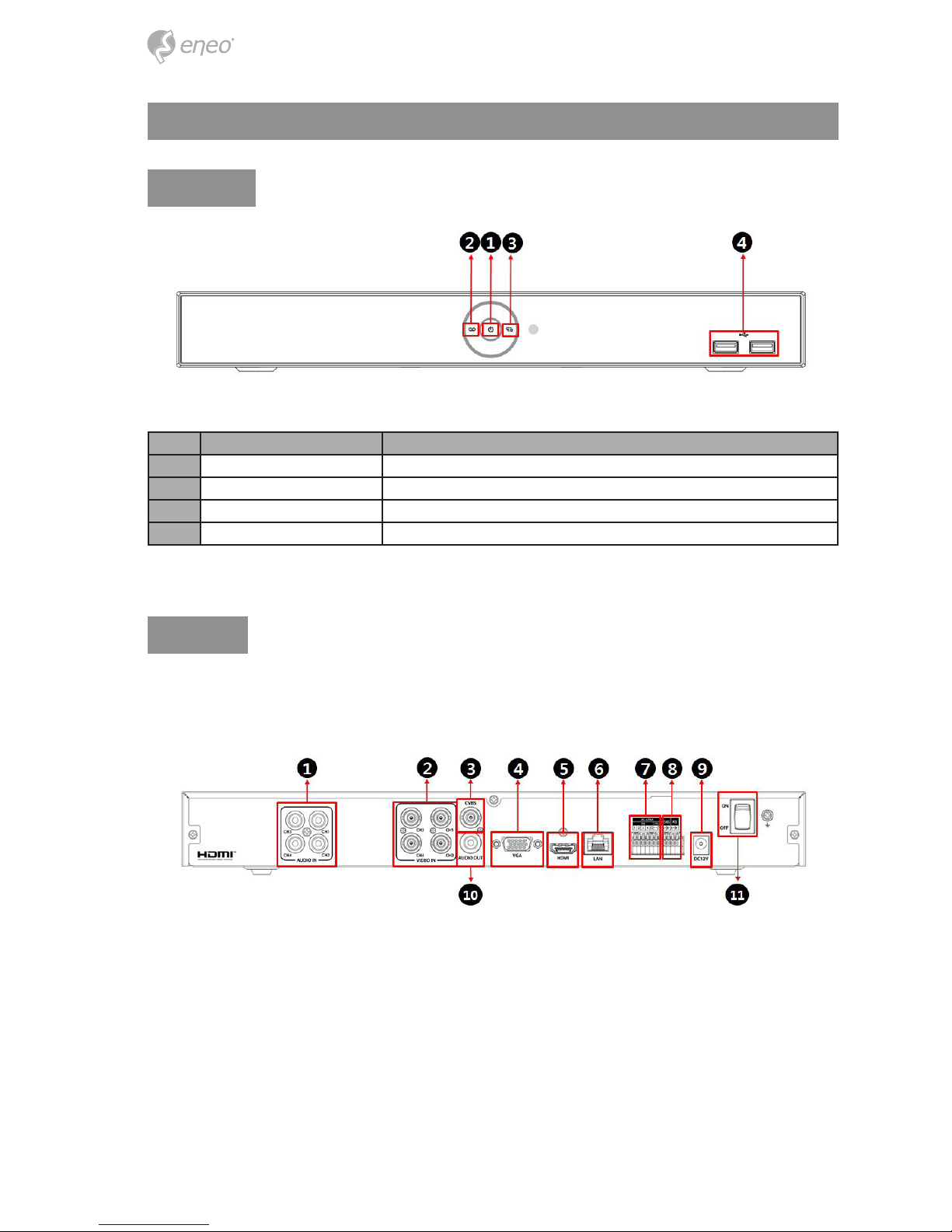
Front
No. Name Function
1 Power status LED Pointing out device on/o.
2 Recording status LED Pointing out recording in process.
3 Network LED With a network viewer, pointing out network in connection.
4 USB port USB port is connected for USB mouse or rmware upgrade, and data back-up.
Rear
4 channel model:
7
EN
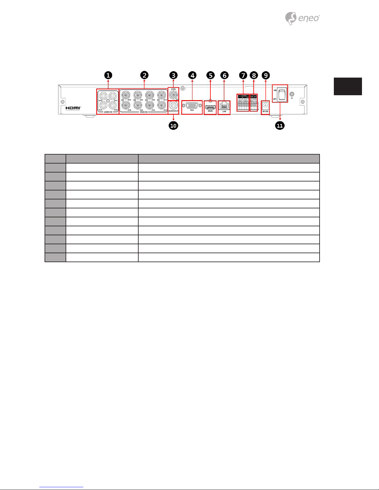
8 channel model:
No. Name Function
1 Audio In Camera audio input port.
2 Video In Camera video input port.
3 CVBS CVBS output port.
4 VGA VGA output port.
5 HDMI HDMI output port.
6 LAN Network connector.
7 Alarm In/Out Alarm connector.
8 RS485 RS-485 communication connector.
9 DC12V Power supply connector.
10 Audio Out Audio output port.
11 Power Switch Power On-o
8
Installation
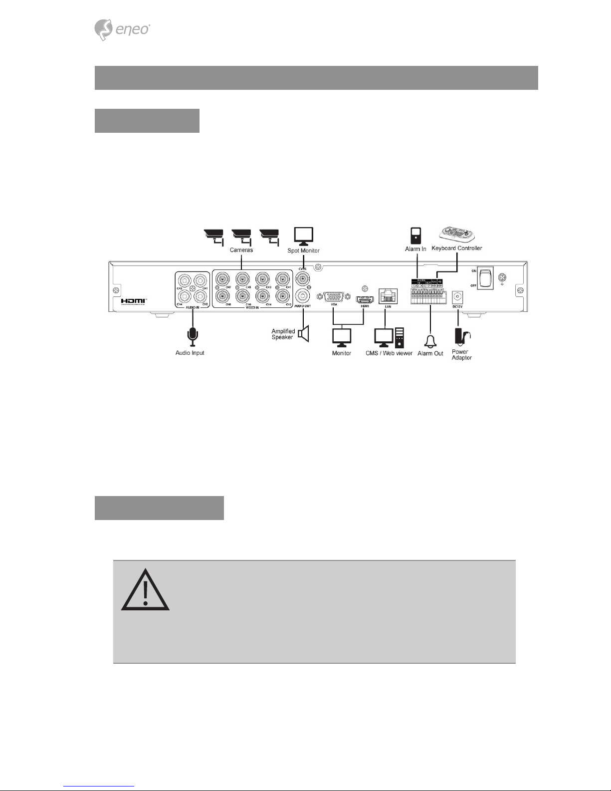
Installation
This chapter describes the way to install DVR.
When installing a device, connect rear of the device with each port on the basis of below
connection map.
The device starts rst like below sequences:
1. Installing HDD
2. Connecting with an exterior device
3. Starting a system
4. Setting an quick setup
Installing HDDs
How to install HDDs in the device:
CAUTION:
• Withdraw the mains plug before installing HDD to reduce
the risk of injury or electrical shock, or device malfunction.
• Make sure to check the compatibility of HDD with the
device.
1. Always switch o and unplug the unit.
2. Unscrew with a screw driver (+) and open the unit cover.
9
EN
3. Install HDD in the bottom case.
4. Connect a data cable and power cable with HDD.
5. Close the cover and tighten screws.
Starting System
Power supply begins with system operation as follows:
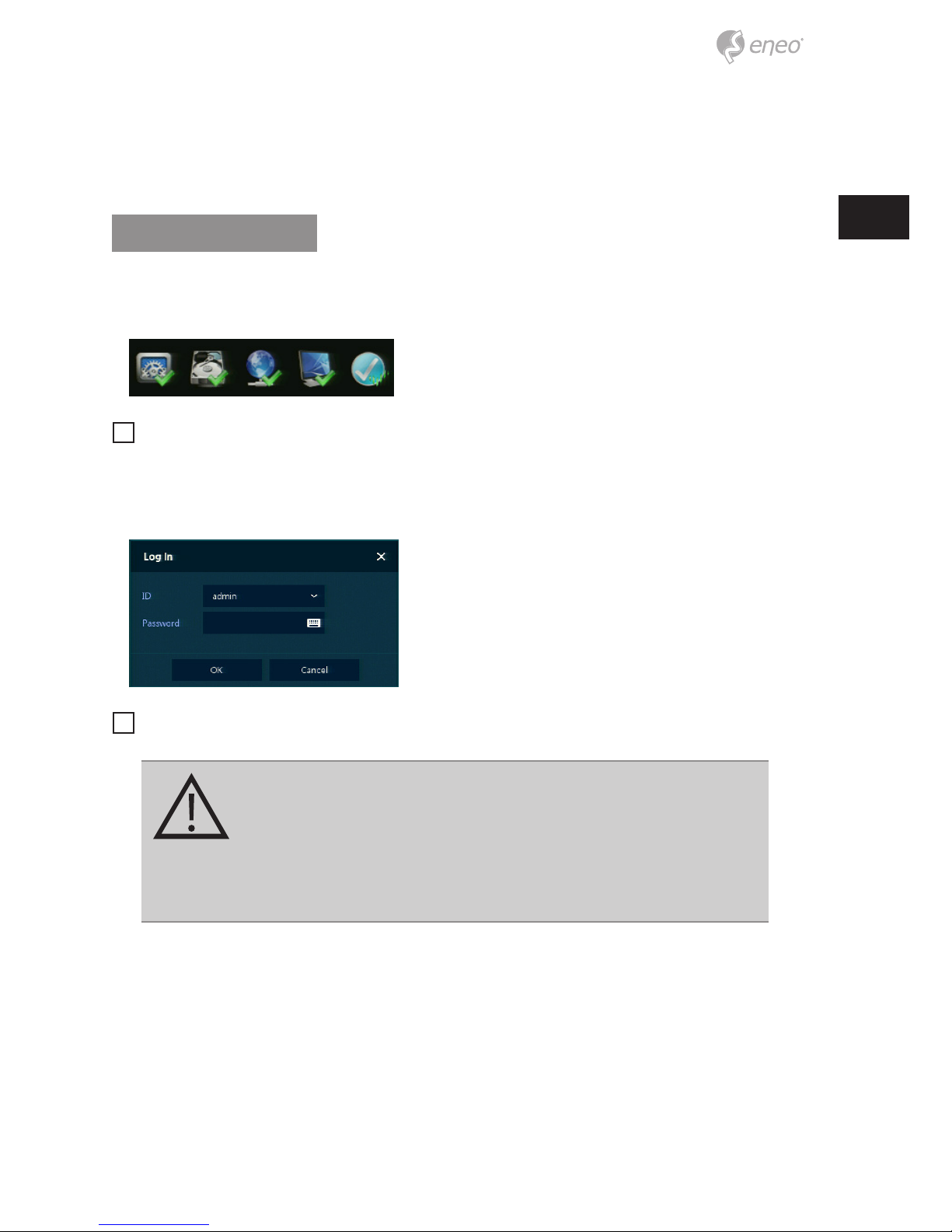
1. Switching on initialize with below icons in order.
i
Notice: Installing new HDD might take more initialize time.
2. With buzzer sounds, the start screen is presented.
3. In Log in screen, enter the ID, Password and press OK.
i
Notice: Default ID & Password is admin/admin
CAUTION:
Please change password after login due to security.
For security reasons, please note in the event the password is
lost the device must be returned to our Service Centre so the
password can be reset.
10
Quick Setup
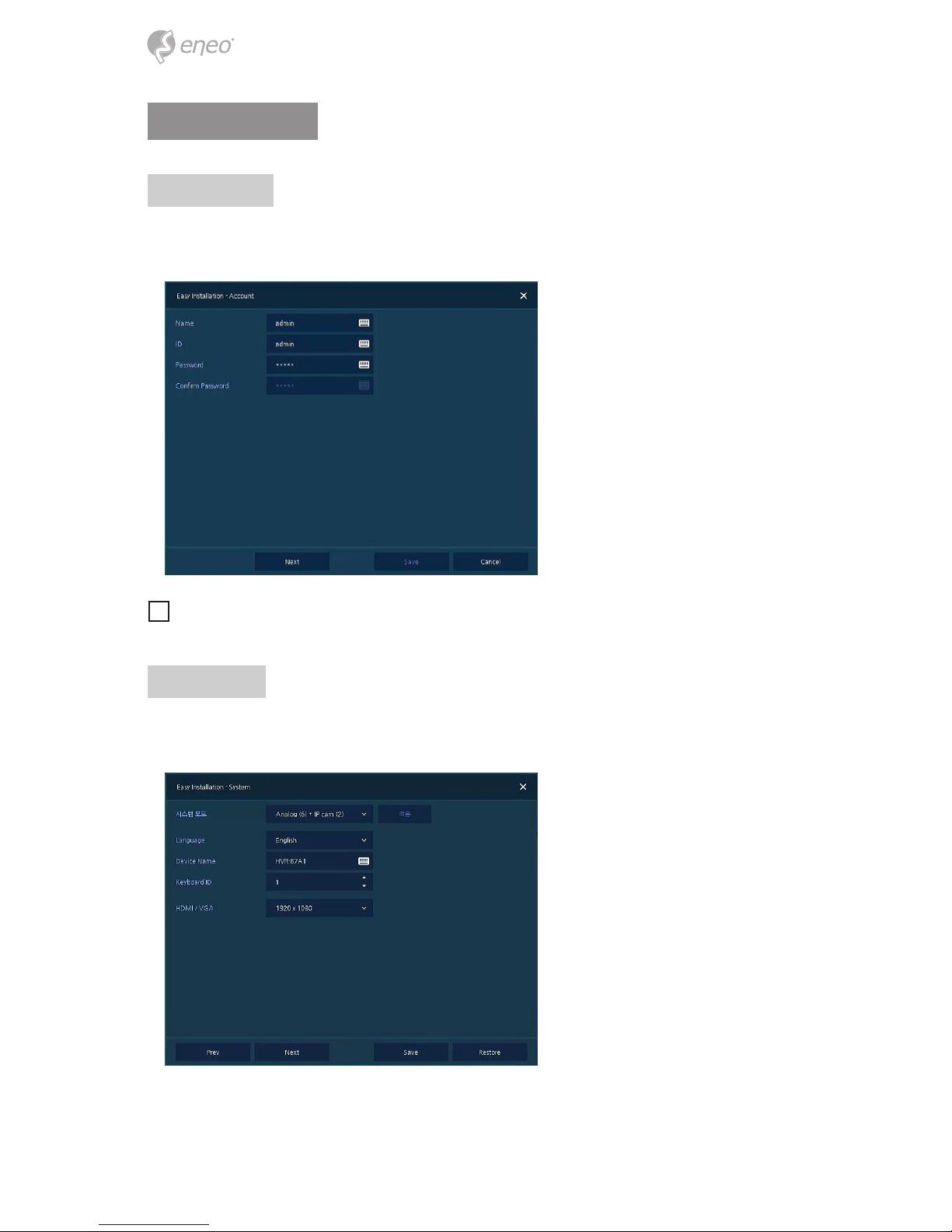
Account
Set ID and Password.
i
Notice: Default ID & Password is admin/admin. Change password for security.
System
Set each item in System setting screen.
• System Mode: Select input video type (analog or analog+IP).
11
EN
• Language: Select system language.
• Device Name: Enter the device name.
• Keyboard ID: To identify device usages in controlling DVR with RS485 through a
keyboard. Selecting the device ID. In case of simultaneous use of equipment, set ID
with dierence.
• HDMI / VGA: Set resolution of a monitor connected to the device.
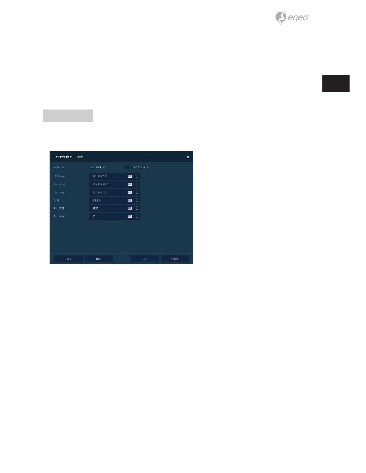
Network
Set each item in Network setting screen.
• WAN Port: Select whether to use static IP or dynamic IP.
• IP Address, Subnet Mask, Gateway, DNS, and Port: As for dynamic IP, enter information in each space.
12
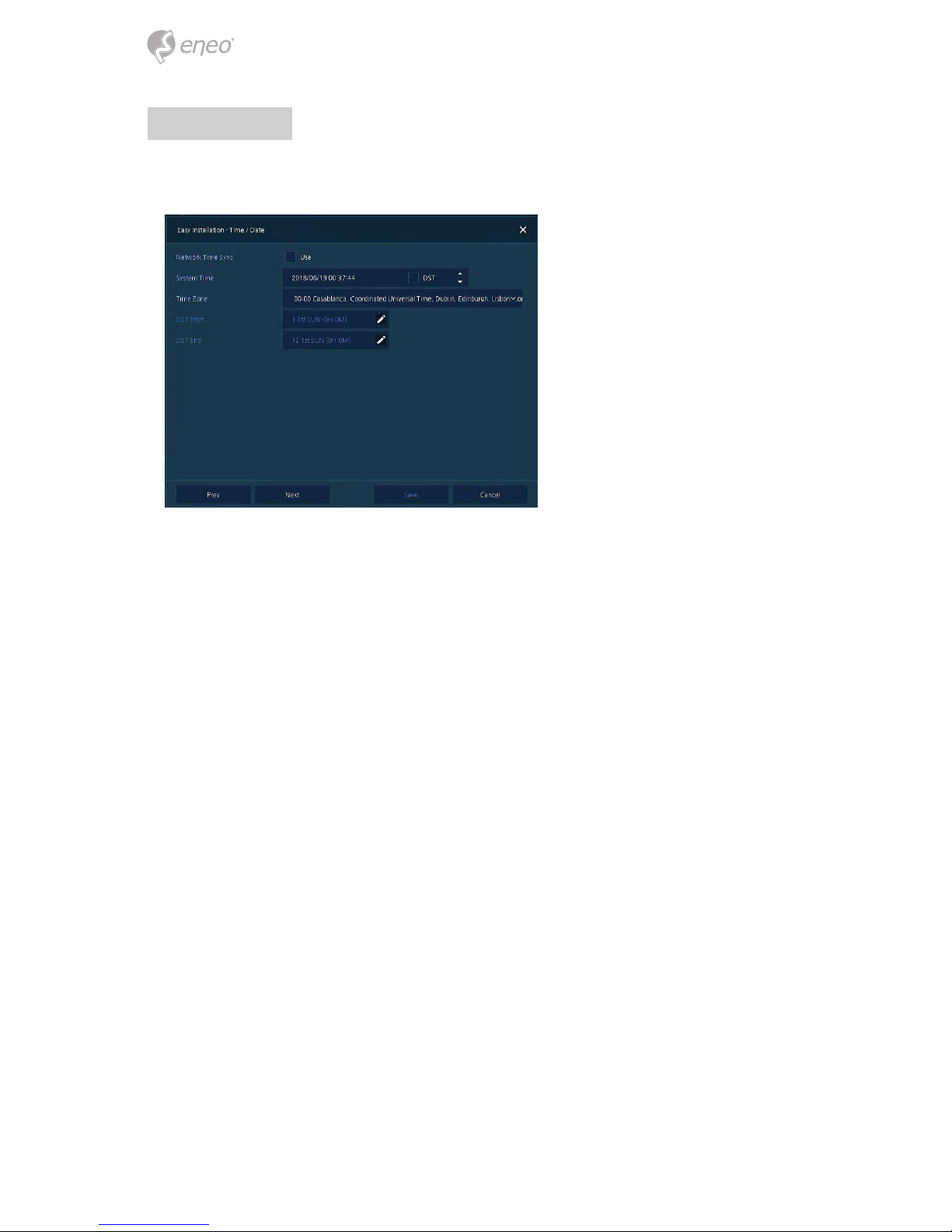
Time/Date
Set each item in Time/Date setting screen.
• Network Time Sync: Select network for synchronizing with time server.
• System Time: Not for synchronizing with network time server, set the device time;
otherwise (applying for Daylight saving time), select DST.
• Time Zone: Select time zone for the system being installed.
• DST Start/End: For applying Daylight saving time, set the application period.
13
EN
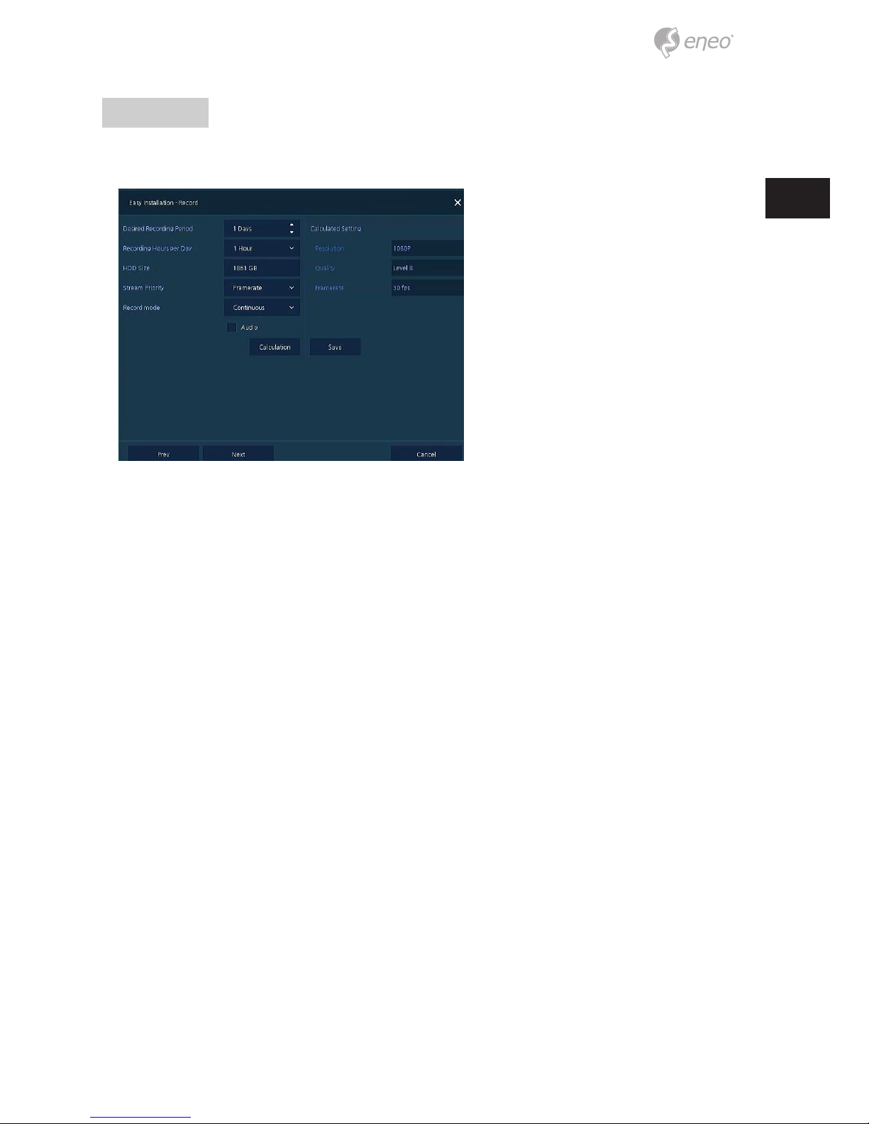
Record
Set each item in Record setting screen.
• Select desired recording period and daily recording hours.
• HDD size will be displayed automatically.
• Select priority of frame rate or resolution.
• Select recording modes as continouse or event.
• Select if audio record or not.
• Click Calculation to see recommended frame rate and resolution.
14
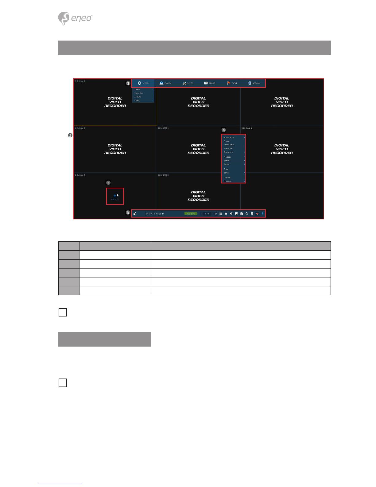
Live Screen Conguration
UI screen is congured like below gure.
No. Item Description
1 Setup menu Setting menu is located in the corner of upper screen.
2 Live screen Show live video of connected cameras.
3 Launcher menu Launcher menu is located in the corner of below screen.
4 Quick menu Clicking the right button of a mouse displays Quick menu.
5 Add to CH Move mouse cursor on the center of window to register IP camera manually.
i
Notice: IP Camera menu will be appeared when Analog+IP cam mode is selected.
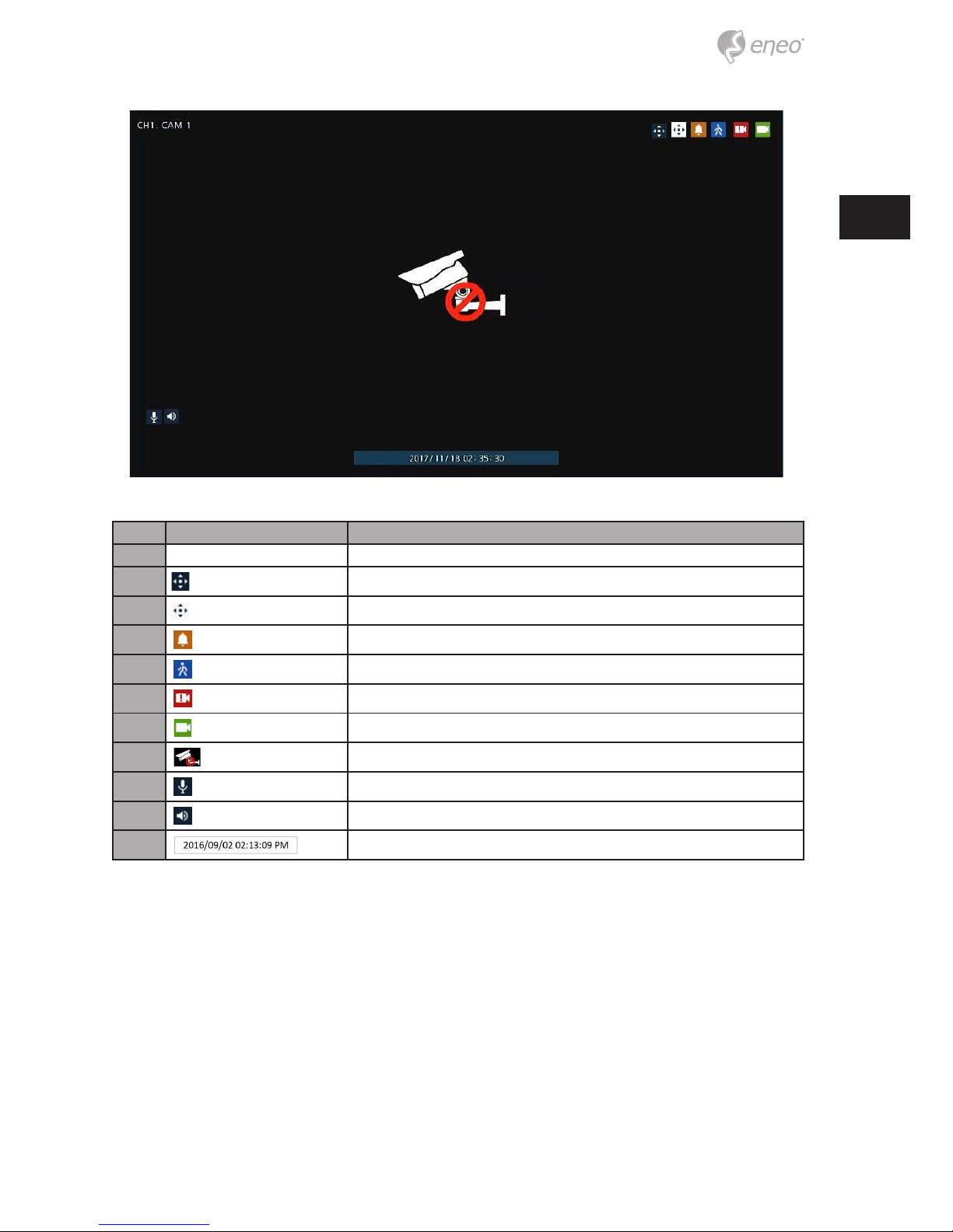
Icons in Live screen
Each icon in the live screen displays a present setting status or a function. UI screen consists of like below.
i
Notice: Chosen live screen is marked as a blue frame; mouse-located live screen is
marked as yellow one.
15
EN
No. Icon Description
1 CH1 CAM1 Channel numbers and camera titles.
2
A camera with PTZ function.
PTZ control function in process.
Recording in alarm event mode.
Recording in motion event mode.
Recording in panic recording mode.
Recording in consecutive recording mode.
3
Video loss icon.
4
Mic on/o.
Speaker on/o.
5
Displaying present time and date.
16
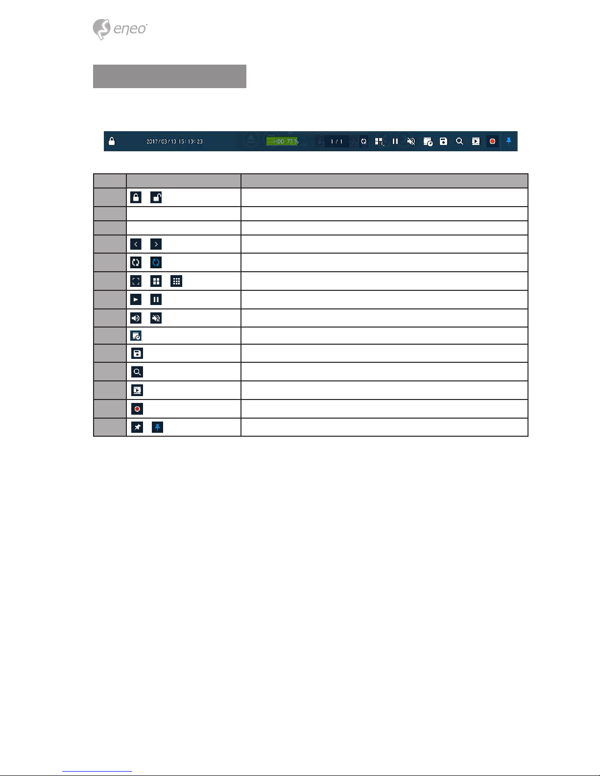
Live Launcher menu
This chapter describes Launcher menu in the bottom of the screen.
No. Item Description
1
Log in/out status and logged in ID.
2 Date & Time Displaying present date and time.
3 HDD Displaying HDD capacity in use.
4
Moving to previous/next partition screen.
5
Displaying live screen in order set (toggle).
6
Selecting partition mode to mark in live screen (single screen, 4- and 9-partition).
7
Stopping or replaying selected live screen images (toggle).
8
Audio on or mute chosen live screen (toggle).
9 Save the bookmark.
10
Make a backup video of users want.
11
Searching recording data (time, event, thumbnail, smart search and text).
12
Playback recorded data.
13
Starting immediate recording of selected channel.
14
Locking or releasing launcher menu (toggle).

17
EN
Quick menu
This chapter depicts Quick menu when users click the right button of the mouse in live
screen.
No. Item Description
1 Screen Mode Selecting the partition mode of live screen (Full, 2X2 and 3X3).
2 Zoom in Magnifying selected live screen (Zoom out, 2 times, 4 times, and 8 times).
3 Freeze Freezes the video selected live screen images (toggle on / o).
4 Speaker Output/Mute Turning on/o a sound speaker.
5 PTZ Control Controlling PTZ functions.
6 Stop Alarm Stopping monitoring alarm output and event.
7 Spot Mode Set the output mode of a spot monitor (Auto, Full, and 3x3).
8 Playback
Playing selected live screen images (before 30 sec, 1 min, 5 min, 10 min, 30 min, 1-hour, Go to last
play time, and Go to last record time).
9 Search Searching recording data (time, event, thumbnail, smart search and text).
10 Backup Backup video users want.
11 Setup Opens the DVRs main set up menu.
12 Camera Registration Opens a pop-up menu for IP camera registration.
13 Status
Opens a pop-up menu showing: device system log, event, and recording status (system log, event,
and record).
14 Log in/Log out Log in/Log out
15 Shutdown Shuts down or restarts the device (shutdown, restart).
18
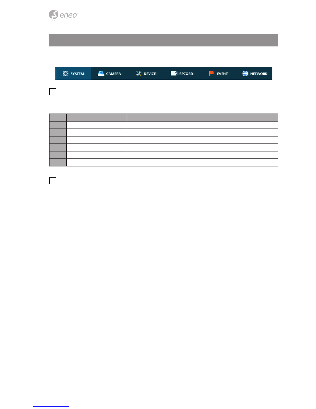
Setup menu
This chapter describes Setup menu in the upper side of the screen.
i
Notice: Setup screen is available to click Setup in Quick menu by clicking the right
button of the mouse.
No. Item Description
1 SYSTEM Setting the system environment.
2 CAMERA Setting the camera.
3 DEVICE Setting the non-camera device connected with the DVR.
4 RECORD Setting the recording parameters.
5 EVENT Setting each event.
6 NETWORK Setting the network environment.
i
Notice: For more details on each section within the Setup menu, please refer to the
main manual contained on the CD supplied with the DVR.

19
EN
Further information
i
Notice: Please download the latest version of our new Management Software
eneo Center from the eneo website: www.eneo-security.com.
Make sure to always upgrade to the latest rmware version available from the eneo website at www.eneo-security.com to receive the latest functionality for your product.
The manual, and other software tools are available on the eneo website at
www.eneo-security.com or on the included CD.
Information on compatible video management software solutions can be found in the
category Videomanagement at www.eneo-security.com.
Open Source Software
The software included in this product contains copyrighted software that is licensed
under open source licenses.
You may obtain the complete corresponding source code from eneo for a period of three
years after the last shipment of this product by sending email to:
opensource@eneo-security.com.
If you want to obtain the complete corresponding source code with a physical medium
such as CD-ROM, the cost of physically performing source distribution might be charged.
For more details about Open Source Software, refer to the eneo website at
www.eneo-security.com or an included product CD.

20
Inhaltsverzeichnis
Komponenten ..............................................................................................................23
Beschreibung ..............................................................................................................24
Vorderseite ........................................................................................................................................................................ 24
Rückseite .......................................................................................................................................................................... 24
Installation ...................................................................................................................26
Installation ........................................................................................................................................................................ 26
Einrichtung der Festplatten ....................................................................................................................................... 26
Systemstart ...................................................................................................................................................................... 27
Schnellkonguration ................................................................................................................................................... 28
Konto ............................................................................................................................................................................ 28
System ......................................................................................................................................................................... 28
Netzwerk ..................................................................................................................................................................... 29
Zeit / Datum ............................................................................................................................................................... 30
Aufzeichnung ............................................................................................................................................................. 31
Konguration der Live-Ansicht .................................................................................32
Symbole in der Live-Ansicht ...................................................................................................................................... 32
Live-Startprogrammmenü ......................................................................................................................................... 34
Schnellmenü ................................................................................................................................................................... 35
Kongurationsmenü ..................................................................................................36
Weitere Informationen ...............................................................................................37

21
DE
Sicherheitsanweisungen
Sicherheitshinweise allgemein
• Bevor Sie das System anschließen und in Betrieb nehmen, lesen Sie zuerst diese Sicherheitshinweise und
die Betriebsanleitung.
• Bewahren Sie die Betriebsanleitung sorgfältig zur späteren Verwendung auf.
• Montage, Inbetriebnahme und Wartung des Systems darf nur durch dafür autorisierte Personen vorgenommen und entsprechend den Installationsanweisungen - unter Beachtung aller mitgeltenden Normen und
Richtlinien - durchgeführt werden.
• Die Geräte gegen Eindringen von Wasser und Feuchtigkeit schützen, dies kann zu dauerhaften Schäden
führen.
• Sollte dennoch Feuchtigkeit eingedrungen sein, die Geräte nie unter diesen Bedingungen einschalten,
sondern zur Überprüfung an eine autorisierte Fachwerkstatt geben.
• Das System darf nie außerhalb der technischen Daten benutzt werden, da es zerstört werden kann.
• Das Gerät ist vor großer Hitze, Staub, Feuchtigkeit und Vibrationseinwirkung zu schützen.
• Um das System von der Versorgungsspannung zu trennen, ziehen Sie das Kabel nur am Stecker heraus.
Ziehen Sie nie direkt am Kabel.
• Verlegen Sie die Verbindungskabel sorgfältig und stellen Sie sicher, dass die Kabel nicht mechanisch beansprucht, geknickt oder beschädigt werden und keine Feuchtigkeit eindringen kann.
• Falls Funktionsstörungen auftreten, benachrichtigen Sie bitte Ihren Lieferanten.
• Wartung und Reparaturen dürfen nur von autorisiertem Fachpersonal ausgeführt werden.
• Vor Önen des Gehäuses ist eine Netztrennung erforderlich.
• Das Gerät darf nur von qualiziertem Servicepersonal geönet werden. Fremdeingrie beenden jeden
Garantieanspruch.
• Anschlusskabel sollten immer nur durch VIDEOR E. Hartig GmbH ausgetauscht werden.
• Verwenden Sie nur Originalersatzteile und Original-Zubehör von VIDEOR E. Hartig GmbH.
• Zur Reinigung der Gehäuse immer nur ein mildes Haushaltsmittel verwenden. Niemals Verdünner oder
Benzin benutzen, dies kann die Oberäche dauerhaft schädigen.
• Bei der Montage muss grundsätzlich darauf geachtet werden, dass vorhandene Dichtungen ordnungsgemäß eingesetzt und bei der Montage nicht verschoben werden. Beschädigte Dichtungen dürfen nicht
mehr verbaut werden und führen zum Erlöschen des Garantieanspruchs.
• Der Errichter ist für die Aufrechterhaltung der Schutzart laut technischer Daten verantwortlich, z.B. durch
Abdichtung des Kabelaustritts mit Silikon.
• Bei Kürzung von exiblen Anschlussleitung sind Aderendhülsen zu verwenden.
• Die Geräte dürfen nur in den im Datenblatt angegebenen Temperatur- und Luftfeuchtigkeitsbereichen
betrieben werden.
Produktspezische Sicherheitshinweise:
• Die Kamera darf nie mit geöneter Blende direkt gegen die Sonne gerichtet werden (dies zerstört den
Sensor).
• Es lässt sich nicht vermeiden, dass im Rahmen der Fertigung und auch beim späteren Gebrauch in gewissem Umfang Feuchtigkeit der Umgebungsluft im Gehäuse vorhanden ist. Bei starken Temperaturschwankungen kann sich die Feuchtigkeit im Gehäuse niederschlagen.
• Um dies in dem sehr dicht abschließenden Gehäuse zu vermeiden, hat der Hersteller bei verschiedenen
Kameratypen Silicagel-Beutel in das Kameragehäuse eingelegt.
• Es ist eine physikalische Gegebenheit, dass diese Silicagel-Beutel nach einer gewissen Zeit eine Sättigung
erreichen. Sie sollten deshalb gegen neue Silicagel-Beutel ausgetauscht werden.
• Bei der Montage muss grundsätzlich darauf geachtet werden, dass vorhandene Dichtungen ordnungsgemäß eingesetzt und bei der Montage nicht verschoben werden. Beschädigte Dichtungen dürfen nicht
mehr verbaut werden und führen zum Erlöschen des Garantieanspruchs.
• In der Nähe des IR-Scheinwerfers ist eine mehrpolige, leicht zugängliche Trennvorrichtung zu installieren,
um das Gerät bei Servicearbeiten frei schalten zu können.
• Die Schutzleiterverbindung muss nach DIN VDE 0100 entsprechend niederohmig ausgeführt werden.
• Nachträgliches Lackieren der Geräteoberäche kann die Funktion beeinträchtigen.
• Durch das Nachlackieren erlischt jeglicher Gewährleistungsanspruch.
22
• Bei abgedunkelter Umgebung und direktem Blick in den IR-Scheinwerfer ist ein Sicherheitsabstand von > 1
m zum Scheinwerfer einzuhalten.
• Unsichtbare LED Strahlung nicht direkt mit optischen Instrumenten (z.B. Lupe, Vergrößerungsglas oder
Mikroskop) betrachten, da dies Augen gefährden kann, LED Klasse 1M.
• Der Betrieb des IR-Scheinwerfers bei defekter Abdeckung oder bei Reparatur ist untersagt.
Hinweis für Geräte der Klasse A
Dies ist ein Gerät der Klasse A. Dieses Gerät kann im Wohnbereich Funktionsstörungen verursachen; in diesem Fall
kann vom Betreiber verlangt werden, angemessene Maßnahmen durchzuführen und dafür aufzukommen.
WEEE-Richtlinie (Elektro- und Elektronik-Altgeräte)
Ordnungsgemäße Entsorgung dieses Produkts (Gilt für die Europäische Union und die anderen Europäischen
Länder mit getrennten Sammelsystemen)
Dieses am Produkt oder in seiner Dokumentation gezeigte Symbol bedeutet, dass es am Ende
seiner Lebensdauer nicht mit dem Hausmüll entsorgt werden darf. Um eventuelle Umwelt- oder
Gesundheitsschäden durch unkontrollierte Abfallbeseitigung zu verhindern, dieses Gerät von
anderen Abfallarten trennen und ordnungsgemäß recyceln, um die nachhaltige Wiederverwendung materieller Ressourcen zu fördern. Haushaltsanwender sollten entweder den Händler, bei
dem sie dieses Produkt gekauft haben, oder ihr örtliches Regierungsbüro kontaktieren, um
Einzelheiten darüber zu erfahren, wo und wie sie dieses Gerät umweltgerecht recyceln können.
Geschäftliche Anwender sollten sich an ihren Lieferanten wenden und die Bedingungen des
Kaufvertrags überprüfen. Dieses Produkt darf zur Entsorgung nicht mit anderen Unternehmensabfällen vermischt
werden.
Grasche Symbole
Bitte beachten Sie die Sicherheitshinweise und lesen Sie diese Anleitung vor Inbetriebnahme sorgfältig durch.
Wichtige Warnhinweise sind mit einem Achtung-Symbol gekennzeichnet.
i
Wichtige Hinweise sind mit einem Hinweis-Symbol gekennzeichnet.

23
DE
Komponenten
Das System wird mit den folgenden Komponenten geliefert:
• DVR
• Installationsanleitung
• CD
• DC-Adapter und Netzkabel
• Maus
• SATA-Kabel
• SATA Stromkabel
• Befestigungsschrauben für Festplatte
 Loading...