

Eneo MPD-62V2812P0A Quick Installation Manual

EN
DE
FR
IT
Quick Installation Guide
1/2.8” HD Dome, Fixed, Indoor,
Day&Night, 1920x1080, Infrared, 2.8-12mm, 12VDC
MPD-62V2812P0A

2
Table of content
Parts supplied ...............................................................................................................5
Part names .....................................................................................................................6
Installation instructions ...............................................................................................7
Pan & Tilt adjustments ..................................................................................................................................................... 8
Zoom & focus adjustments ............................................................................................................................................8
Detach the dome camera from the easy adaptor ............................................................................................9
Open the dome cover .................................................................................................................................................9
Power supply connections .......................................................................................................................................... 10
Operating instructions ...............................................................................................11
Using OSD controller..................................................................................................................................................... 11
Description of the OSD control operation .............................................................................................. 11
Using Video Format Switch ......................................................................................................................................... 11
DIP SWITCH setting................................................................................................................................................... 11
Joystick setting ........................................................................................................................................................... 12
OSD menu startup ......................................................................................................................................................... 12
OSD menu table ............................................................................................................................................................. 13
Further information ....................................................................................................14

3
EN
Safety instructions
General safety instructions
• Before switching on and operating the system, rst read this safety advice and the operating instructions.
• Keep the operating instructions in a safe place for later use.
• Installation, commissioning and maintenance of the system may only be carried out by authorised
individuals and in accordance with the installation instructions - ensuring that all applicable standards and
guidelines are followed.
• Protect the devices from water penetration and humidity, since these can cause lasting damage.
• Should moisture nevertheless enter the system, under no circumstance switch on the devices under these
conditions, instead send them for examination to an authorised specialist workshop.
• The system must never be used outside of the technical specications, since this can destroy it.
• The device must be protected from excesses of heat, dust, humidity and vibration.
• When separating the system from the voltage supply, only ever use the plug to pull out the cable. Never
pull directly on the cable itself.
• Lay the connecting cables carefully and check that they are not mechanically stressed, kinked or damaged
and that no humidity can penetrate into them.
• In the event of a malfunction, please inform your supplier.
• Maintenance and repairs may only be carried out by authorised specialist personnel.
• The system must be isolated from the power supply before opening the housing.
• The device may only be opened by qualied service personnel. Unauthorised access invalidates any
warranty claim.
• Connection cables should always be exchanged through Videor E. Hartig GmbH.
• Use only original spare parts and accessories from Videor E. Hartig GmbH.
• The housing should only be cleaned using a mild domestic cleaning agent. Never use solvents or petrol as
these can permanently damage the surface.
• During installation, it is essential to ensure that the seals provided are correctly installed and that they are
not displaced during installation. Damaged seals must not be installed and will invalidate any warranty.
• The installer is responsible for the maintenance of the enclosure as per the technical data, e.g. by sealing
the cable outlets with silicone.
• Wire end ferrules should be used when shortening the exible connection cables.
• The devices may only be operated in the temperature range indicated in the data sheet and within the
dened air humidity range.
Product - Specic Safety Instructions
• The camera may never be pointed directly at the Sun with the aperture open (this will destroy the sensor).
• It is unavoidable that during manufacture and to a certain extent during later use, humidity will be present
in the ambient air within the device’s housing. In the event of large temperature uctuations, this humidity
may condense inside the housing.
• To avoid this condensation inside the very tightly sealed housing, the manufacturer has inserted silica gel
sachets in the housing of the various camera types.
• It is however a physical given, that these silica gel bags will reach saturation after a certain amount of time.
They should therefore be replaced with new silica gel sachets.
• During installation, it is essential to ensure that the seals provided are correctly installed and that they are
not displaced during installation. Damaged seals must not be installed and will invalidate any warranty.
• A multipolar, easily accessible isolation device should be installed in the proximity of the IR Spotlight, in
order to disconnect the device from the power supply for service work.
• The earth connection must be made according to the low impedance requirement of DIN VDE 0100.
• Subsequent painting of the equipment surface can impair the function.
• Any warranty claim is invalidated by subsequent painting.
• A safety margin of > 1m from the spotlight must be maintained when viewing directly into the IR Spotlight
in a darkened environment.
• Do not look directly at invisible LED radiation using optical instruments (e.g. a reading glass, magnifying
glass or microscope), since this can endanger the eyes, LED Class 1M.
• Operation of the IR spotlight with a defective cover or during repair is prohibited.
4
Class A device note
This is a Class A device. This device can cause malfunctions in the living area; in such an event, the operator may
need to take appropriate measures to compensate for these.
WEEE (Waste Electronical & Electronic Equipment)
Correct Disposal of This Product (Applicable in the European Union and other European countries with separate
collection systems).
This marking shown on the product or its literature, indicates that it should not be disposed with
other household wastes at the end of its working life. To prevent possible harm to the environment
or human health from uncontrolled waste disposal, please separate this from other types of wastes
and recycle it responsibly to promote the sustainable reuse of material resources. Household users
should contact either the retailer where they purchased this product, or their local government
oce, for details of where and how they can take this item for environmentally safe recycling.
Business users should contact their supplier and check the terms and conditions of the purchase
contract. This product should not be mixed with other commercial wastes for disposal.
Graphical symbols
Please pay attention to the safety instructions, and carefully read through this instruction guide before initial
operation.
Important points of warning are marked with a caution symbol.
i
Important points of advice are marked with a notice symbol.
5
EN
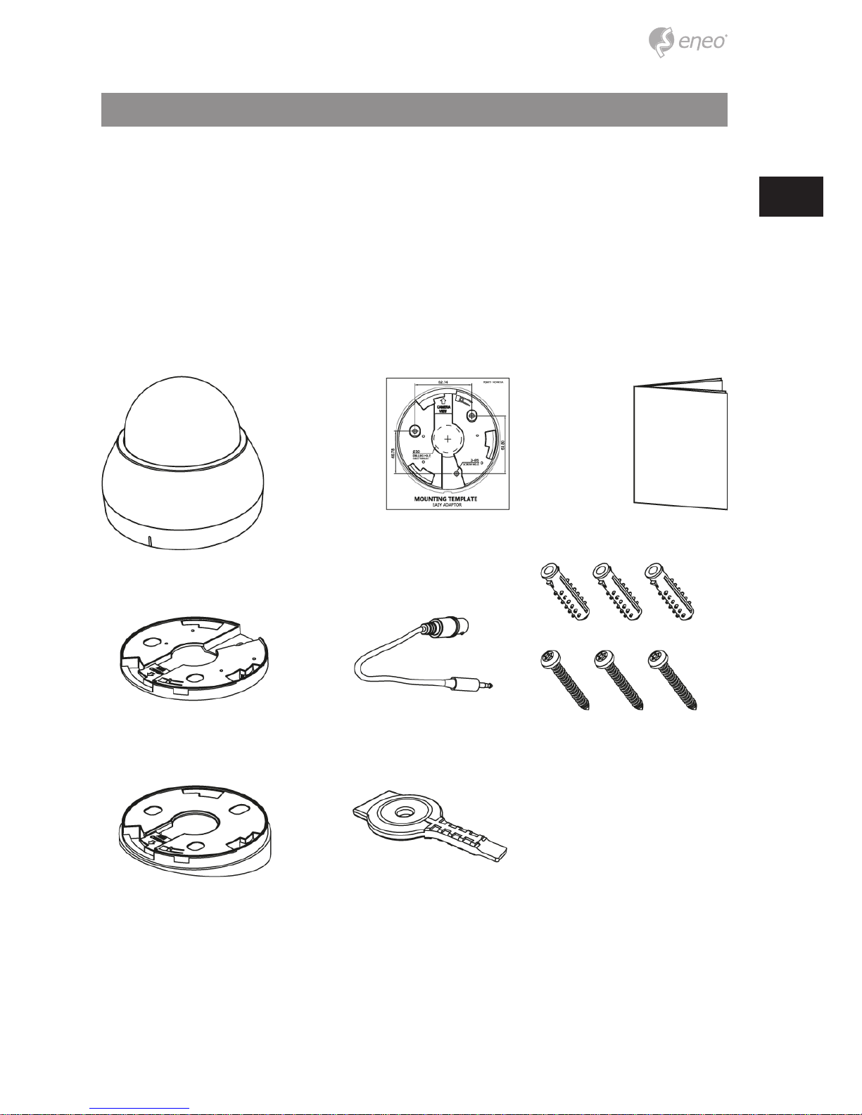
Parts supplied
• Dome Camera
• Operating Instruction
• Mounting Template
• Plastic Anchor: 6 x 30 mm (3x)
• Mounting Screw: 3.5 x 25 mm (3x)
• Easy Adaptor (Flat type)
• Easy Adaptor (Tilted type)
• Open & Adjust Driver (1x)
• Video Sub-out Cable (1x) (LED Type)
6
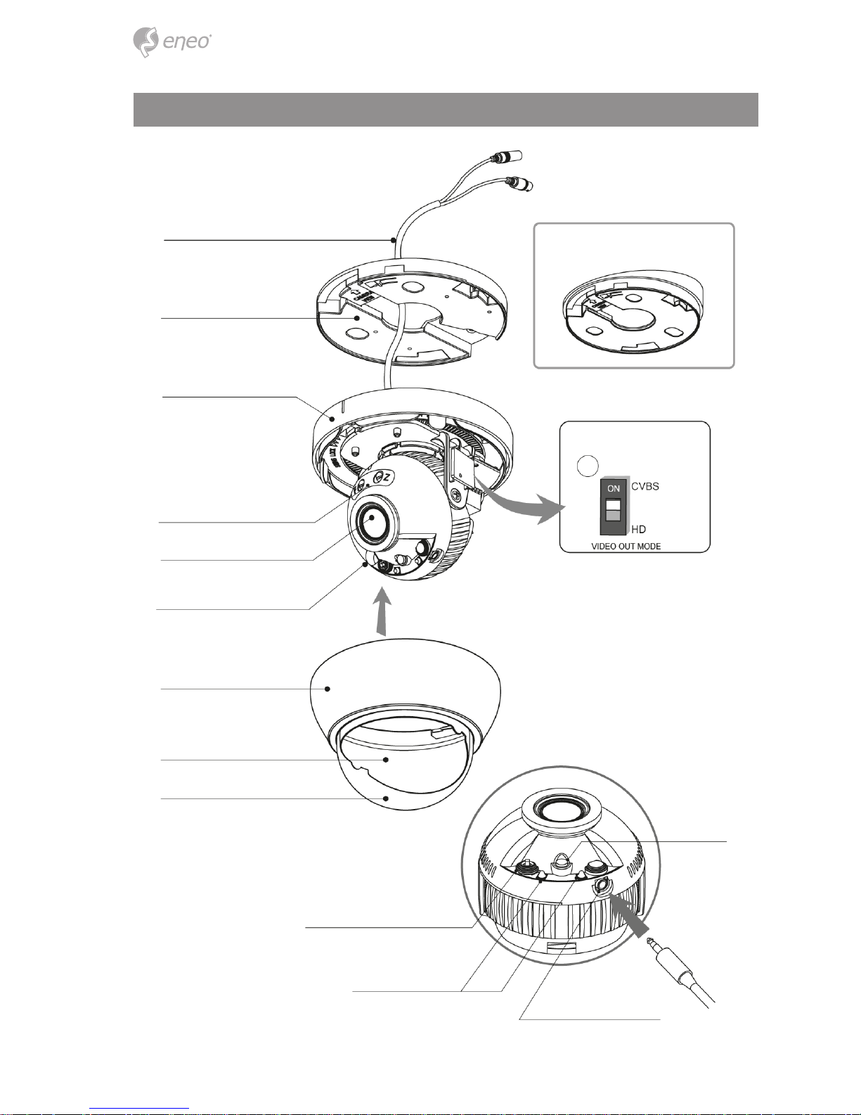
Part names
3-Axis Gimbal
Easy Adaptor (Tilted type)
Power Cable
Easy Adaptor (Flat type)
Dome Base
Focus & Zoom adjustment
Lens
Light Sensor
Dome Cover
Bubble Shield
Video format DIP Switch
Bubble
OSD Control & Video format Joystick
SMD LEDs
Video Sub-out connector
7
EN
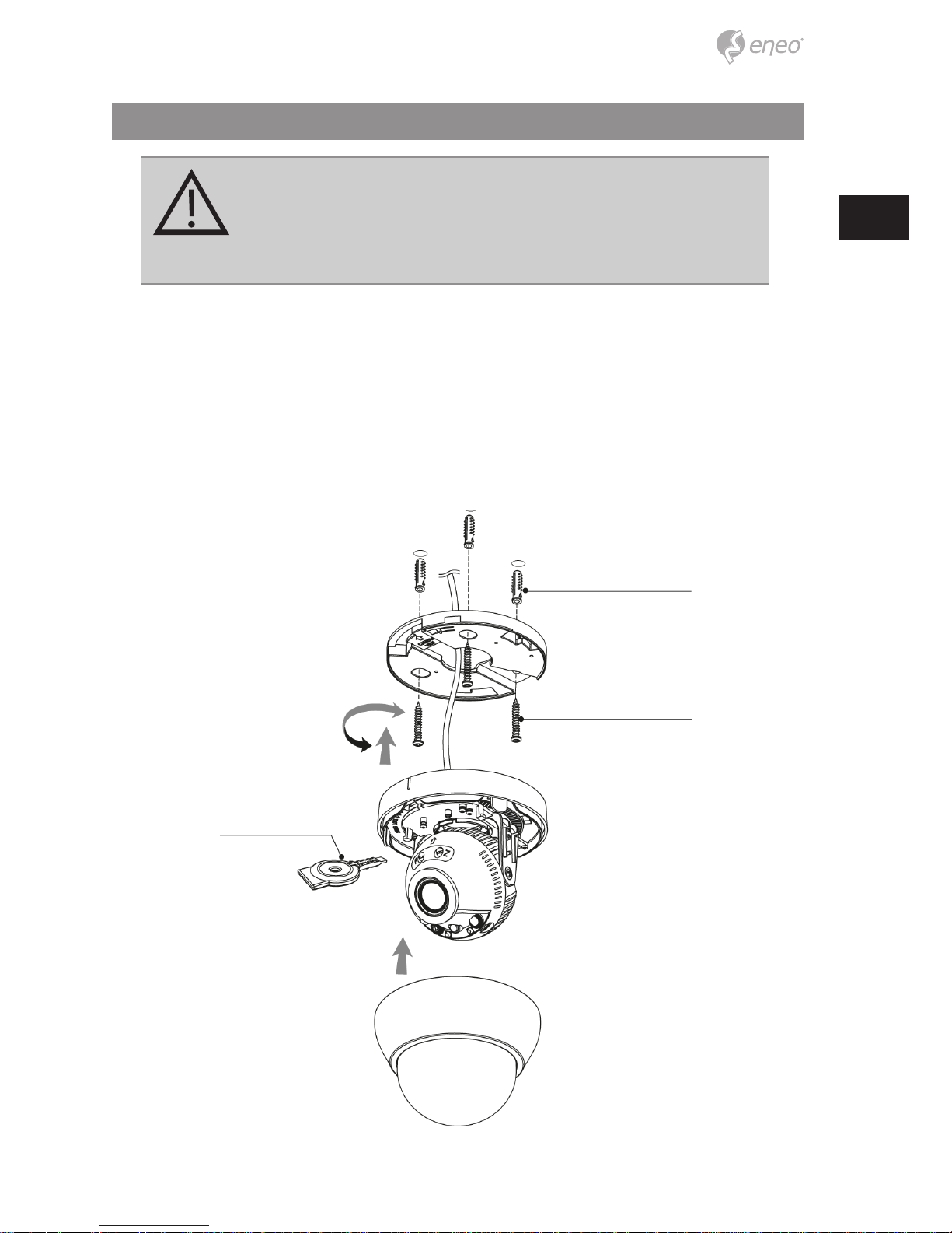
Installation instructions
CAUTION: The camera’s base should be attached to a structural
object, such as concrete, hard wood, wall stud or ceiling rafter
that supports the weight of the camera. If necessary use appropriate mounting material (e.g. anchors) instead of the material
enclosed with the camera.
1. Drill three holes for mounting on the ceiling or wall.
2. Place the Easy Adaptors at the pre-drilled installation position and x it by using
mounting screws.
3. Route the power/video cable to the connecting place.
4. Attach the dome base assembly to the Easy Adaptor.
5. Adjust the camera’s viewing angle (Pan, Tilt, Rotation) (Then remove the caution
sticker.)
6. Assemble the dome cover to the dome base unit.
Plastic Anchor (6x30 mm)
Open & Adjust Driver
Mounting Screw (3.5x25 mm)
OPEN
LOCK
8
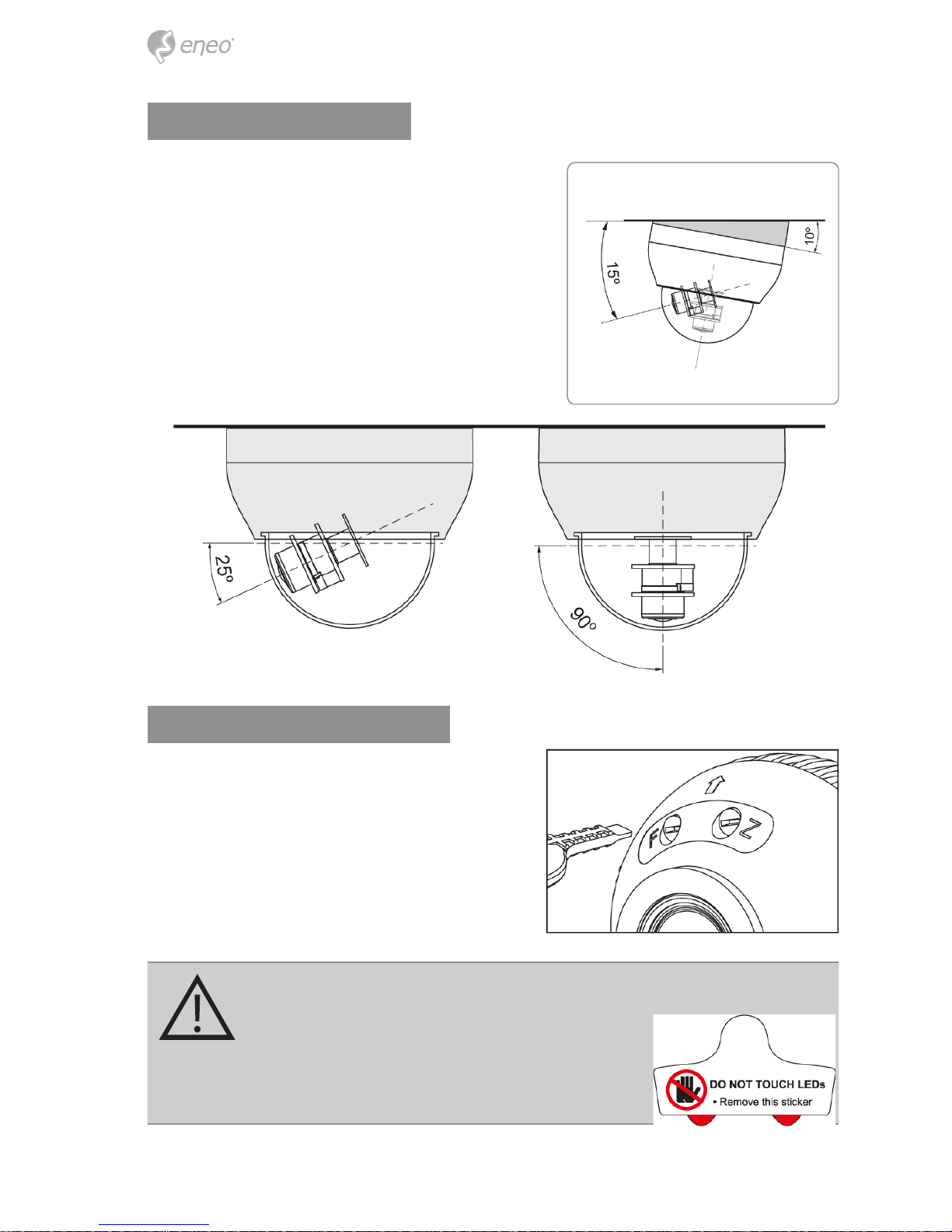
Pan & Tilt adjustments
1. Pan limit: Pan is limited to +/- 165°. Do NOT
force to rotate the gimbal over the limit to
prevent from the internal damage.
2. Tilt limit: Tilt is limited to 25° min ~ 90°
max. with reference to the ceiling when the
inclination of camera module is 0°, that is,
the image is aligned horizontally.
3. Inclination limit (Horizontal image alignment): Inclination is limited to +/- 60° max.
Zoom & focus adjustments
Use the open & adjust driver supplied.
• Turn the Focus gear until the sharpest focus
is made.
• Adjust the zoom for the proper viewing
angle.
CAUTION:
Be careful with the IR LEDs when you control the
OSD setting with the joystick.
Remove the sticker on the gimbal after the OSD
setting
9
EN
CAUTION:
Extreme care should be taken NOT to scratch the bubble dome surface
while the camera installing or adjusting.
Care should be taken the cable is NOT to be damaged, kinked or exposed
in the hazardous area.
Tighten enough the dome cover xing screws so that there should be NO
gap between Lens hood and clear bubble to avoid the light inow from
IR LEDs.
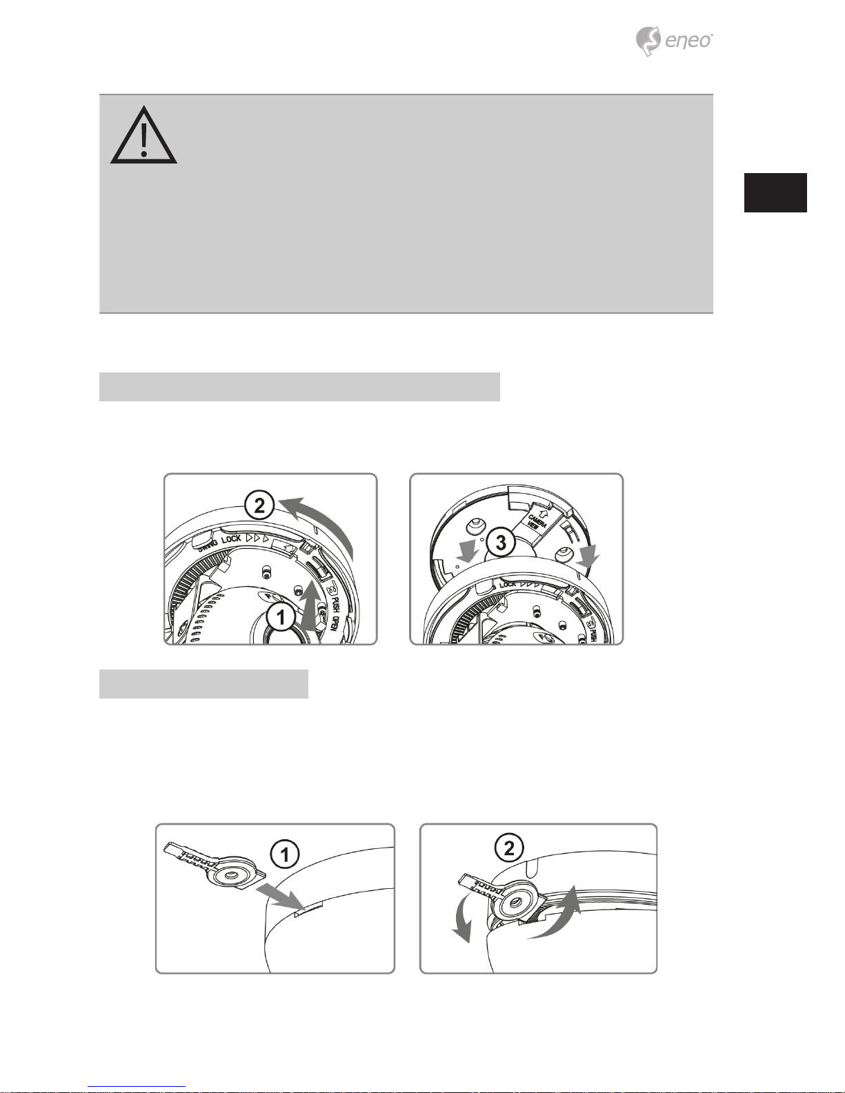
Detach the dome camera from the easy adaptor
Push the hook on the dome base and swing the dome base to counterclockwise. Then
detach the dome camera from the installed easy adaptor.
Open the dome cover
1. Insert wide side of Open Tool into the lock of Dome Cover.
2. Hold the Dome housing with one hand and turn the open tool until Dome Cover
is suciently open.
3. Once Dome Base and Dome Cover are detached, press the edge of Dome Cover
and pull it down with hands.
10
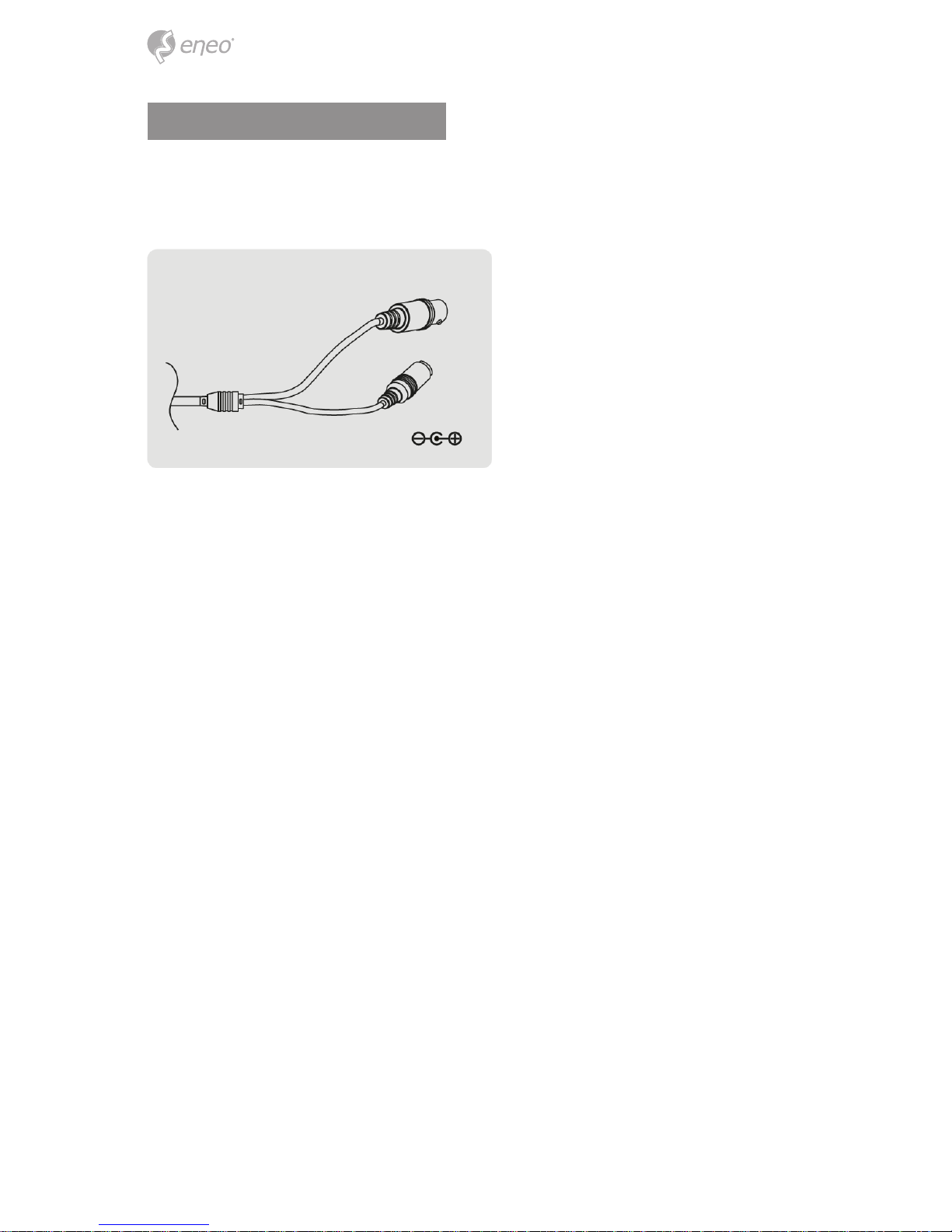
Power supply connections
Camera can be operated with the regulated or unregulated DC12V but the regulated
power supply of DC12V is recommended. Camera is protected from the damage by the
reverse connection of polarity.
VIDEO (BNC)
Power
11
EN
Operating instructions
Using OSD controller
Setup menu can be accessed and controlled by OSD control joy stick on the gimbal of the
camera unit. Five commands are available with the joy stick. The design of OSD could be
dierent according to the Model.
Description of the OSD control operation
1. SET Key (●) : Access to the menu or enter the setting. To enter the main menu,
press the Set Key down.
2. UP/DOWN Key (▲/▼) : Choose the desired sub-menu and to move the cursor up or
down.
3. LEFT/RIGHT Key (◄/►) : Set up the value of the selected menu. Used to adjust the
desired menu selection and to move the cursor left or right.
i
If OSD menu is adjusted in specic video format, adjusted value is applied to only
related video format. For example, if the menu is adjusted in CVBS mode, adjusted value
is applied to CVBS video only.
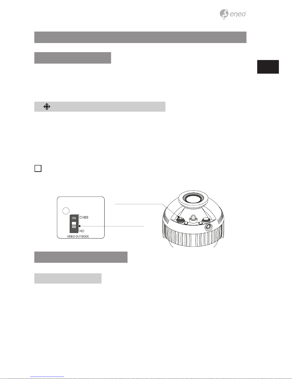
Using Video Format Switch
DIP SWITCH setting
The DIP SWITCH setting has rst priority.
If the switch is set to CVBS, only CVBS output is available for both main video output and
sub-out. Please be advised that camera generates only one video output for both main
video output and sub-out. It takes 3~5 seconds when video format is changing. The
default DIP SWITCH setting is CVBS mode.
12
Joystick setting
Switching video format is available by Video format joystick. If you want to set the HD
video format, set the DIP Switch to HD mode rst. Then set the one of HD Video format by
joystick. The default setting is TVI mode.
1. TVI mode (Up ▲) : Moving up direction for about 3 seconds to TVI mode.
2. CVBS (Down ▼) : Moving down direction for about 3 seconds to CVBS.
3. AHD (Left ◄) : Moving left direction for about 3 seconds to AHD.
4. CVI mode (Right ►) : Moving right direction for about 3 seconds to CVI mode.
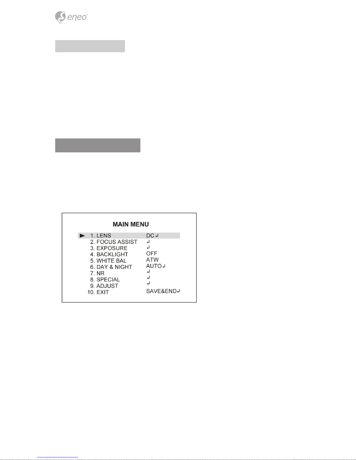
OSD menu startup
Press the ‘OSD menu SET key’ down to access the setup menu mode.
• EXIT : Enters ‘EXIT’ menu.
• RETURN : Returns to the previous menu.
• DEFAULT : Restores to factory default.
13
EN
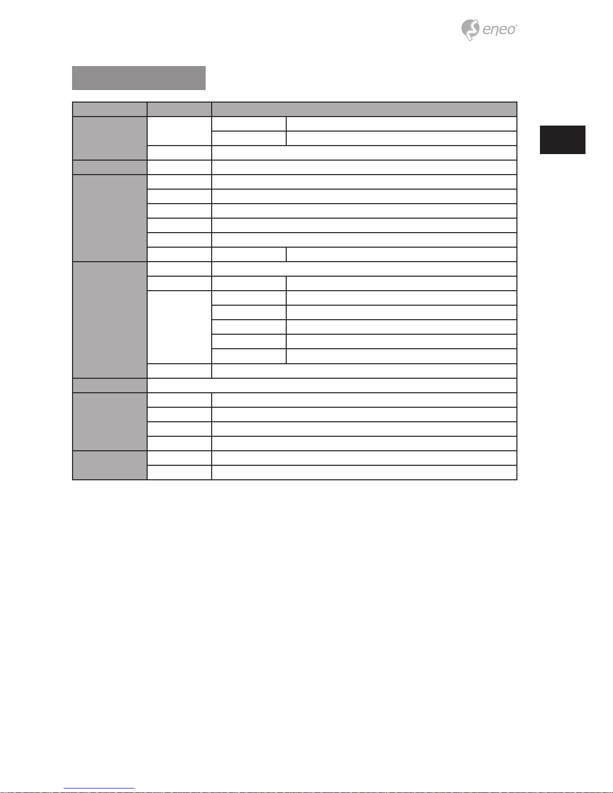
OSD menu table
MENU SUB MENU CONFIGURATION
LENS
DC
MODE INDOOOR, OUTDOOR
IRIS SPEED
MANUAL
FOCUS ASSIST DN DWELL
EXPOSURE
SHUTTER FLK, 1/60(1/50), 1/30(1/25), AUTO, x30~x2, 1/50000~1/200
AGC 0~15
SENS UP OFF, AUTO (2x~30x)
BRIGHTNESS 1~100
D-WDR ON(LEVEL:0~8), AUTO, OFF
DEFOG OFF, AUTO POS/SIZE, GRADATION(0~2), DEFAULT
BACKLIGHT
OFF
HSBLC SELECT AREA1~4
DISPLAY ON, OFF
BLACK MASK ON, OFF
LEVEL 0~100
MODE ALL DAY, NIGHT(AGC LEVEL)
DEFAULT
BLC LEVEL, AREA, DEFAULT
WHITE BAL ATW, AWB, MANUAL(BLUE/RED GAIN), OUTDOOR, INDOOR, AWC->SET
DAY & NIGHT
AUTO D->N(AGC/CDS), D->N(DELAY), N->D(AGC/CDS), N->D(DELAY)
EXT D->N(DELAY), N->D(DELAY)
B/W BURST, IR SMART, IR PWN*
COLOR
NR
2DNR LOW, MIDDLE, HIGH
3DNR(AHD only) LOW, MIDDLE, HIGH
14
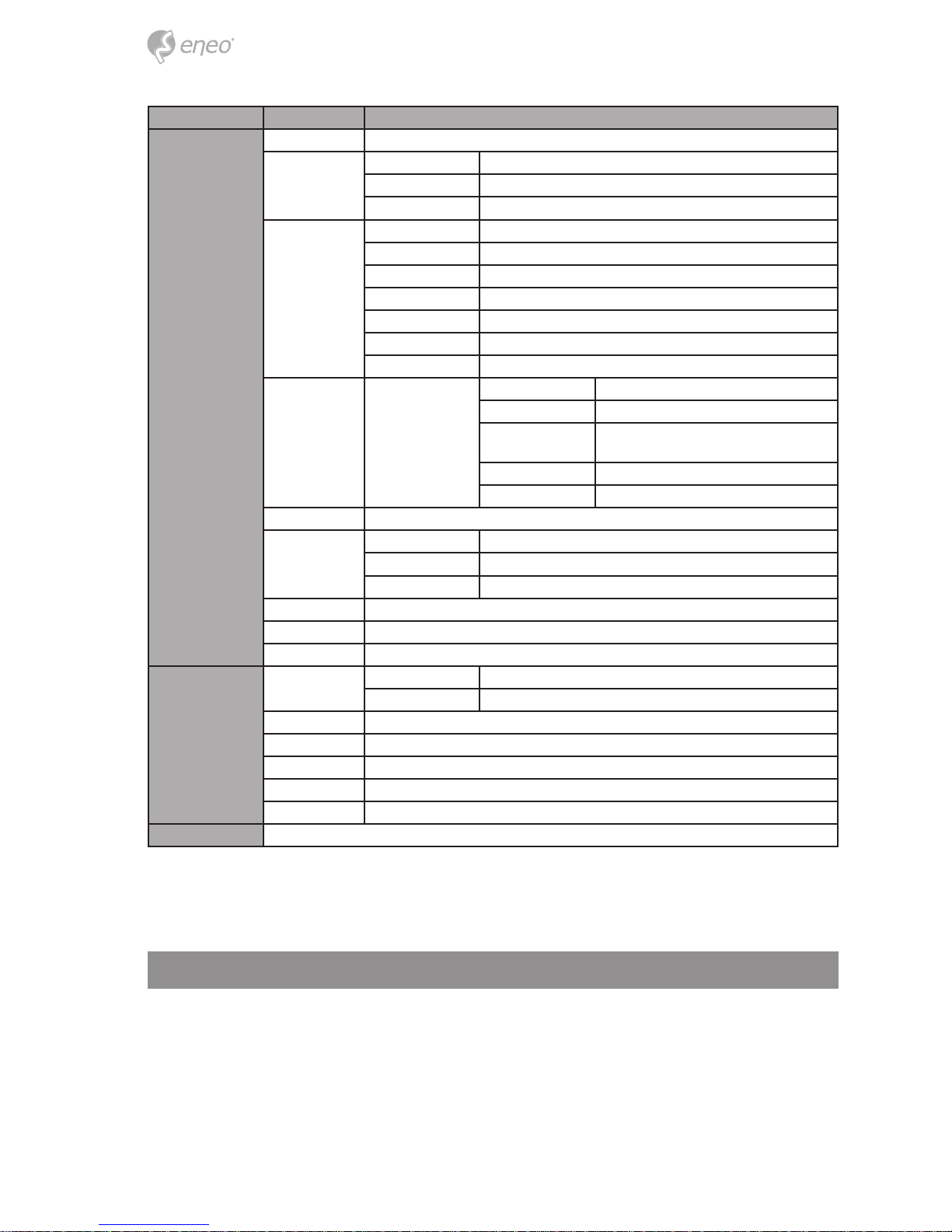
MENU SUB MENU CONFIGURATION
SPECIAL
CAM TITLE OFF, ON
D-EFFECT
FREEZE OFF, ON
MIRROR MIRROR, V-FLIP, ROTATE, OFF
NEG. IMAGE
MOTION
SELECT AREA1~4
DISPLAY OFF, ON(POSITION, SIZE)
SENSITIVITY 0~100
COLOR Green, Red, White, Blue
TRANS 0.00~1.00
ALARM* VIEW TYPE, OSD VIEW, ALARM OUT, TIME
DEFAULT
PRIVACY OFF, ON
SELECT AREA1~4
DISPLAY COLOR, INV, MOSAIC
COLOR
White, User, Cyan, Green,
Yellow, Blue, Red, Black
TRANS 0.25~1.00
DEFAULT
LANGUAGE ENG, TUR, NED, POR, RUS, POL, SPA, ITA, FRA, GER, CHN1/CHN2
DEFECT
LIVE DPC AGC LEVEL(0~255), LEVEL(0~100)
WHITE DPC SENS-UP, POS/SIZE, START, DPC VIEW, AGC
BLACK DPC POS/SIZE, START, DPC VIEW, LEVEL
RS-485* CAM ID, ID DISPLAY, BAUDRATE
VERSION FW VER, ISP VER, AHD RX VER
COLOR BAR OFF, ON
ADJUST
SHARPNESS
AUTO LEVEL, START AGC, END AGC
OFF
MONITOR LDC, CRT
LSC OFF, ON
VIDEO OUT NTSC/PAL
COMET (CVBS) OFF, ON
MONITOR OUT(HD) AHD, TVI mode, CVI mode, CVBS
EXIT SAVE&END, NOT SAVE, RESET
(*) Not Available
Further information
The manual is also available from the eneo web site at www.eneo-security.com.

15
DE
Inhaltsverzeichnis
Lieferumfang ...............................................................................................................18
Bezeichnungen von Gerätekomponenten ...............................................................19
Installationsanweisungen ..........................................................................................20
Einstellung von Schwenkung und Neigung ......................................................................................................... 21
Zoom- und Fokuseinstellung ..................................................................................................................................... 21
Trennen der Dome-Kamera vom Easy-Adapter ............................................................................................. 22
Önen der Dome-Abdeckung ............................................................................................................................. 22
Stromversorgungsanschlüsse .................................................................................................................................... 23
Betriebsanleitung .......................................................................................................24
Bildschirmmenü-Steuerung verwenden ............................................................................................................... 24
Beschreibung der Bedienung der Bildschirmsteuerung ................................................................... 24
Verwendung des Videoformat-Schalters ............................................................................................................... 24
DIP-Schalter-Einstellung ......................................................................................................................................... 24
Joystick-Einstellung .................................................................................................................................................. 25
Bildschirmmenü starten .............................................................................................................................................. 25
Bildschirmmenü-Übersicht ........................................................................................................................................ 26
Weitere Informationen ...............................................................................................27

16
Sicherheitsanweisungen
Sicherheitshinweise allgemein
• Bevor Sie das System anschließen und in Betrieb nehmen, lesen Sie zuerst diese Sicherheitshinweise und
die Betriebsanleitung.
• Bewahren Sie die Betriebsanleitung sorgfältig zur späteren Verwendung auf.
• Montage, Inbetriebnahme und Wartung des Systems darf nur durch dafür autorisierte Personen vorgenommen und entsprechend den Installationsanweisungen - unter Beachtung aller mitgeltenden Normen und
Richtlinien - durchgeführt werden.
• Die Geräte gegen Eindringen von Wasser und Feuchtigkeit schützen, dies kann zu dauerhaften Schäden
führen.
• Sollte dennoch Feuchtigkeit eingedrungen sein, die Geräte nie unter diesen Bedingungen einschalten,
sondern zur Überprüfung an eine autorisierte Fachwerkstatt geben.
• Das System darf nie außerhalb der technischen Daten benutzt werden, da es zerstört werden kann.
• Das Gerät ist vor großer Hitze, Staub, Feuchtigkeit und Vibrationseinwirkung zu schützen.
• Um das System von der Versorgungsspannung zu trennen, ziehen Sie das Kabel nur am Stecker heraus.
Ziehen Sie nie direkt am Kabel.
• Verlegen Sie die Verbindungskabel sorgfältig und stellen Sie sicher, dass die Kabel nicht mechanisch beansprucht, geknickt oder beschädigt werden und keine Feuchtigkeit eindringen kann.
• Falls Funktionsstörungen auftreten, benachrichtigen Sie bitte Ihren Lieferanten.
• Wartung und Reparaturen dürfen nur von autorisiertem Fachpersonal ausgeführt werden.
• Vor Önen des Gehäuses ist eine Netztrennung erforderlich.
• Das Gerät darf nur von qualiziertem Servicepersonal geönet werden. Fremdeingrie beenden jeden
Garantieanspruch.
• Anschlusskabel sollten immer nur durch VIDEOR E. Hartig GmbH ausgetauscht werden.
• Verwenden Sie nur Originalersatzteile und Original-Zubehör von VIDEOR E. Hartig GmbH.
• Zur Reinigung der Gehäuse immer nur ein mildes Haushaltsmittel verwenden. Niemals Verdünner oder
Benzin benutzen, dies kann die Oberäche dauerhaft schädigen.
• Bei der Montage muss grundsätzlich darauf geachtet werden, dass vorhandene Dichtungen ordnungsgemäß eingesetzt und bei der Montage nicht verschoben werden. Beschädigte Dichtungen dürfen nicht
mehr verbaut werden und führen zum Erlöschen des Garantieanspruchs.
• Der Errichter ist für die Aufrechterhaltung der Schutzart laut technischer Daten verantwortlich, z.B. durch
Abdichtung des Kabelaustritts mit Silikon.
• Bei Kürzung von exiblen Anschlussleitung sind Aderendhülsen zu verwenden.
• Die Geräte dürfen nur in den im Datenblatt angegebenen Temperatur- und Luftfeuchtigkeitsbereichen
betrieben werden.
Produktspezische Sicherheitshinweise:
• Die Kamera darf nie mit geöneter Blende direkt gegen die Sonne gerichtet werden (dies zerstört den
Sensor).
• Es lässt sich nicht vermeiden, dass im Rahmen der Fertigung und auch beim späteren Gebrauch in gewissem Umfang Feuchtigkeit der Umgebungsluft im Gehäuse vorhanden ist. Bei starken Temperaturschwankungen kann sich die Feuchtigkeit im Gehäuse niederschlagen.
• Um dies in dem sehr dicht abschließenden Gehäuse zu vermeiden, hat der Hersteller bei verschiedenen
Kameratypen Silicagel-Beutel in das Kameragehäuse eingelegt.
• Es ist eine physikalische Gegebenheit, dass diese Silicagel-Beutel nach einer gewissen Zeit eine Sättigung
erreichen. Sie sollten deshalb gegen neue Silicagel-Beutel ausgetauscht werden.
• Bei der Montage muss grundsätzlich darauf geachtet werden, dass vorhandene Dichtungen ordnungsgemäß eingesetzt und bei der Montage nicht verschoben werden. Beschädigte Dichtungen dürfen nicht
mehr verbaut werden und führen zum Erlöschen des Garantieanspruchs.
• In der Nähe des IR-Scheinwerfers ist eine mehrpolige, leicht zugängliche Trennvorrichtung zu installieren,
um das Gerät bei Servicearbeiten frei schalten zu können.
• Die Schutzleiterverbindung muss nach DIN VDE 0100 entsprechend niederohmig ausgeführt werden.
• Nachträgliches Lackieren der Geräteoberäche kann die Funktion beeinträchtigen.
• Durch das Nachlackieren erlischt jeglicher Gewährleistungsanspruch.

17
DE
• Bei abgedunkelter Umgebung und direktem Blick in den IR-Scheinwerfer ist ein Sicherheitsabstand von > 1
m zum Scheinwerfer einzuhalten.
• Unsichtbare LED Strahlung nicht direkt mit optischen Instrumenten (z.B. Lupe, Vergrößerungsglas oder
Mikroskop) betrachten, da dies Augen gefährden kann, LED Klasse 1M.
• Der Betrieb des IR-Scheinwerfers bei defekter Abdeckung oder bei Reparatur ist untersagt.
Hinweis für Geräte der Klasse A
Dies ist ein Gerät der Klasse A. Dieses Gerät kann im Wohnbereich Funktionsstörungen verursachen; in diesem Fall
kann vom Betreiber verlangt werden, angemessene Maßnahmen durchzuführen und dafür aufzukommen.
WEEE-Richtlinie (Elektro- und Elektronik-Altgeräte)
Ordnungsgemäße Entsorgung dieses Produkts (Gilt für die Europäische Union und die anderen Europäischen
Länder mit getrennten Sammelsystemen)
Dieses am Produkt oder in seiner Dokumentation gezeigte Symbol bedeutet, dass es am Ende
seiner Lebensdauer nicht mit dem Hausmüll entsorgt werden darf. Um eventuelle Umwelt- oder
Gesundheitsschäden durch unkontrollierte Abfallbeseitigung zu verhindern, dieses Gerät von
anderen Abfallarten trennen und ordnungsgemäß recyceln, um die nachhaltige Wiederverwendung materieller Ressourcen zu fördern. Haushaltsanwender sollten entweder den Händler, bei
dem sie dieses Produkt gekauft haben, oder ihr örtliches Regierungsbüro kontaktieren, um
Einzelheiten darüber zu erfahren, wo und wie sie dieses Gerät umweltgerecht recyceln können.
Geschäftliche Anwender sollten sich an ihren Lieferanten wenden und die Bedingungen des
Kaufvertrags überprüfen. Dieses Produkt darf zur Entsorgung nicht mit anderen Unternehmensabfällen vermischt
werden.
Grasche Symbole
Bitte beachten Sie die Sicherheitshinweise und lesen Sie diese Anleitung vor Inbetriebnahme sorgfältig durch.
Wichtige Warnhinweise sind mit einem Achtung-Symbol gekennzeichnet.
i
Wichtige Hinweise sind mit einem Hinweis-Symbol gekennzeichnet.
 Loading...