

Eneo MCB-64A0003M0A, MPC-54A0003M0A, MPD-64A0003P0A User Manual

User Manual
1/2.9” HD Camera,
2560x1440, Day&Night, AF Zoom,
WDR, 3.2~9mm, Infrared, IP67
MCB-64A0003M0A
EN

2
Table of content
Parts supplied ....................................................................................................... 5
Part names ............................................................................................................ 6
Installation instructions ....................................................................................... 7
Operating instructions ......................................................................................... 12
Sunshield Assembling .......................................................................................... 11
Using OSD controller ................................................................................................................................. 12
1. ZOOM / FOCUS .................................................................................................................................... 15
2. EXPOSURE .............................................................................................................................................. 18
3. SCENE ENHANCE ................................................................................................................................. 19
4. 3D-NR ...................................................................................................................................................... 21
5. DAY / NIGHT ......................................................................................................................................... 21
6. PICT. ADJUST ....................................................................................................................................... 23
7. SPECIAL .................................................................................................................................................. 24
8. SYSTEM ................................................................................................................................................... 26
9. EXIT .......................................................................................................................................................... 27
OSD menu startup .................................................................................................................................... 13
OSD Menu Setup ................................................................................................ 15
Further information ............................................................................................. 27
3
EN
Safety instructions
General safety instructions
•
• Keep the operating instructions in a safe place for later use.
• Installation, commissioning and maintenance of the system may only be carried out by authorised
individuals and in accordance with the installation instructions - ensuring that all applicable standards and
guidelines are followed.
• Protect the devices from water penetration and humidity, since these can cause lasting damage.
• Should moisture nevertheless enter the system, under no circumstance switch on the devices under these
conditions, instead send them for examination to an authorised specialist workshop.
•
• The device must be protected from excesses of heat, dust, humidity and vibration.
• When separating the system from the voltage supply, only ever use the plug to pull out the cable. Never
pull directly on the cable itself.
• Lay the connecting cables carefully and check that they are not mechanically stressed, kinked or damaged
and that no humidity can penetrate into them.
• In the event of a malfunction, please inform your supplier.
• Maintenance and repairs may only be carried out by authorised specialist personnel.
• The system must be isolated from the power supply before opening the housing.
•
• Connection cables should always be exchanged through Videor E. Hartig GmbH.
• Use only original spare parts and accessories from Videor E. Hartig GmbH.
• The housing should only be cleaned using a mild domestic cleaning agent. Never use solvents or petrol as
these can permanently damage the surfa
ce.
• During installation, it is essential to ensure that the seals provided are correctly installed and that they are
not displaced during installation. Damaged seals must not be installed and will invalidate any warranty.
• The installer is responsible for the maintenance of the enclosure as per the technical data, e.g. by sealing
the cable outlets with silicone.
•
• The devices may only be operated in the temperature range indicated in the data sheet and within the
dened air humidity range.
• The camera may never be pointed directly at the Sun with the aperture open (this will destroy the sensor).
• It is unavoidable that during manufacture and to a certain extent during later use, humidity will be present
may condense inside the housing.
• To avoid this condensation inside the very tightly sealed housing, the manufacturer has inserted silica gel
sachets in the housing of the various camera types.
• It is however a physical given, that these silica gel bags will reach saturation after a certain amount of time.
They should therefore be replaced with new silica gel sachets.
• During installation, it is essential to ensure that the seals provided are correctly installed and that they are
not displaced during installation. Damaged seals must not be installed and will invalidate any warranty.
• A multipolar, easily accessible isolation device should be installed in the proximity of the IR Spotlight, in
order to disconnect the device from the power supply for service work.
• The earth connection must be made according to the low impedance requirement of DIN VDE 0100.
• Subsequent painting of the equipment surface can impair the function.
• Any warranty claim is invalidated by subsequent painting.
• A safety margin of > 1m from the spotlight must be maintained when viewing directly into the IR Spotlight
in a darkened environment.
• Do not look directly at invisible LED radiation using optical instruments (e.g. a reading glass, magnifying
glass or microscope), since this can endanger the eyes, LED Class 1M.
• Operation of the IR spotlight with a defective cover or during repair is prohibited.
Before switching on and operating the system, rst read this safety advice and the operating instructions.
The system must never be used outside of the technical specications, since this can destroy it.
The device may only be opened by qualied service personnel. Unauthorised access invalidates any
warranty claim.
Wire end ferrules should be used when shortening the exible connection cables.
Product - Specic Safety Instructions
4
Class A device note
This is a Class A device. This device can cause malfunctions in the living area; in such an event, the operator may
need to take appropriate measures to compensate for these.
WEEE (Waste Electronical & Electronic Equipment)
Correct Disposal of This Product (Applicable in the European Union and other European countries with separate
collection systems).
This marking shown on the product or its literature, indicates that it should not be disposed with
other household wastes at the end of its working life. To prevent possible harm to the environment
or human health from uncontrolled waste disposal, please separate this from other types of wastes
and recycle it responsibly to promote the sustainable reuse of material resources. Household users
should contact either the retailer where they purchased this product, or their local government
Business users should contact their supplier and check the terms and conditions of the purchase
contract. This product should not be mixed with other commercial wastes for disposal.
Graphical symbols
Please pay attention to the safety instructions, and carefully read through this instruction guide before initial
operation.
Important points of warning are marked with a caution symbol.
i
Important points of advice are marked with a notice symbol.
5
EN
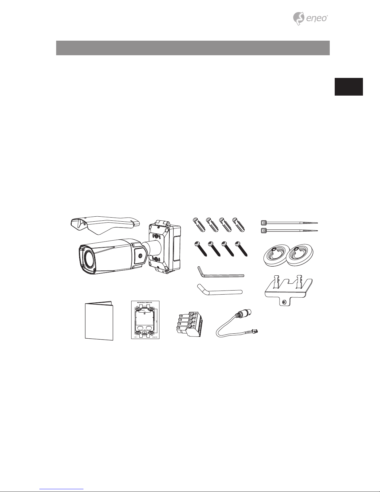
Parts supplied
• Camera
• Operating Instruction
• Mounting Template
• Plastic Anchor: 6 x 30mm (4x)
• Mounting Screw: 4 x 30mm (4x)
• Hex Wrench: 3mm (1x)
• Hinge Pin (1x)
• Cable Tie (2x)
• Grommet (2x)
• Cable xation plate with Fixing screw
• Wiring Connector
• Video Sub-out Cable (1pc)
6
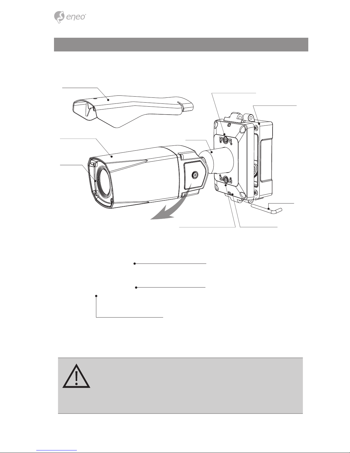
Part names
Dual
window
Body Case
Sunshield
2x Lock/Unlock Screw
2x Water drain
Hinge Pin
Bracket
Junction Box Top
Junction Box Base
Inside of Opening Cover
OSD Control Joy Stick
CAUTION:
Extreme care should be taken NOT to scratch the window in front of lens
Care should be taken the cable is NOT to be damaged, kinked or exposed
in the hazardous area. Do not expose the camera directly to a strong
light source such as the sun or spot light.
Video Sub-out Connector
Video format Switch
7
EN
Installation instructions
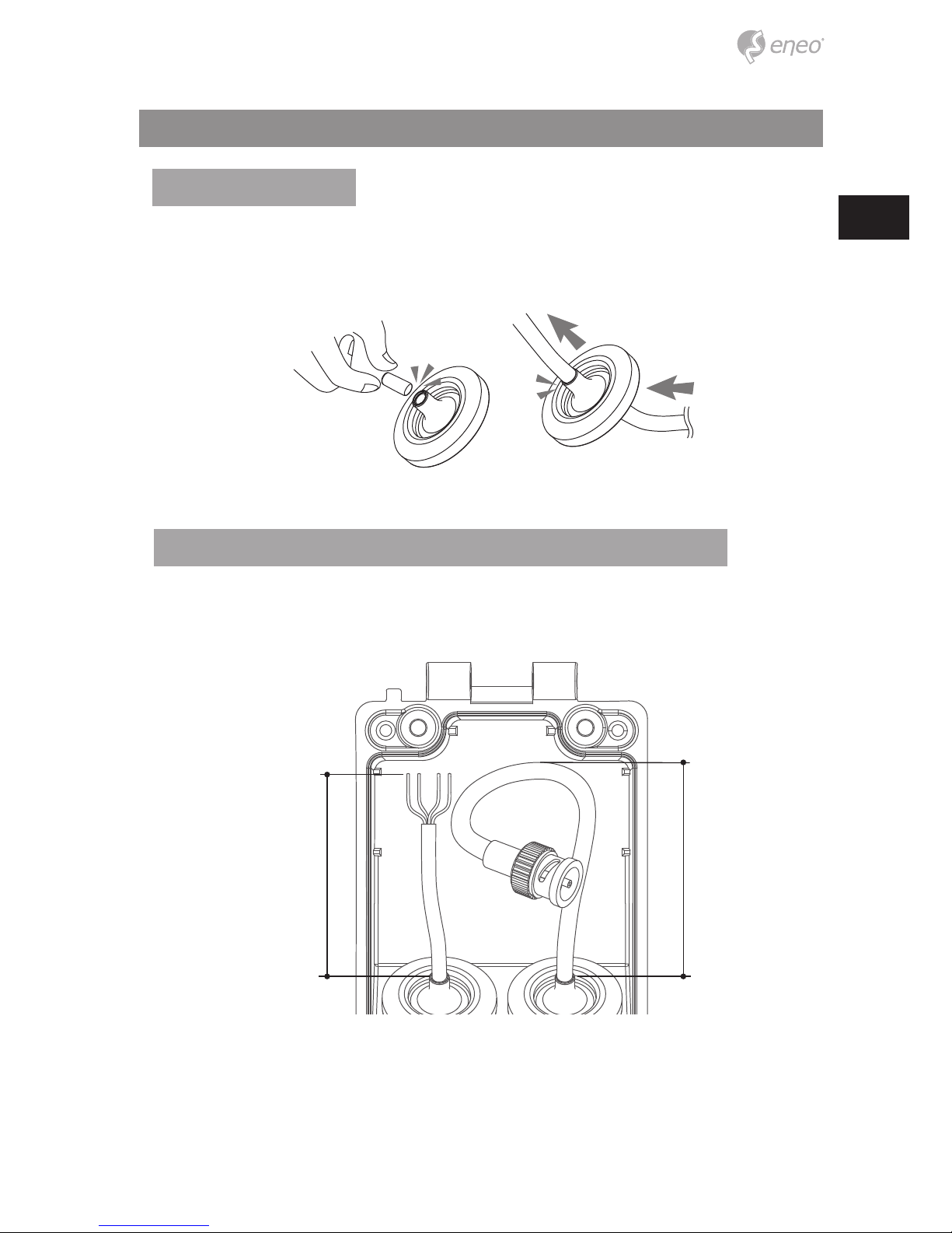
Tear o the cocks of grommets properly and pull up the grommet so that sealing can
wrap the cable properly as illustrated. If it doesn’t wrap the cable properly, it could cause
the water leakage problem.
• BNC CABLE: 180mm~190mm
• Power CABLE: 70mm~80mm including cable stripping section
total: 70~80mm
total: 180~190mm
Recommended cable length into the Junction box base
Using Grommet
8
1
3
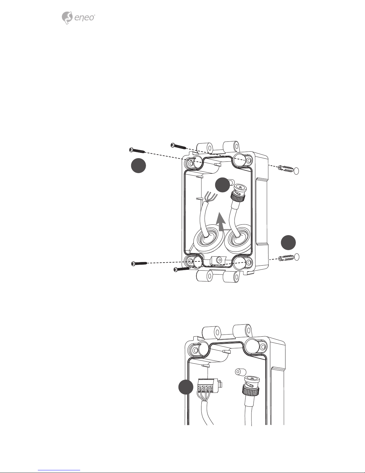
4. Connect the cable wiring with wiring connector.
2
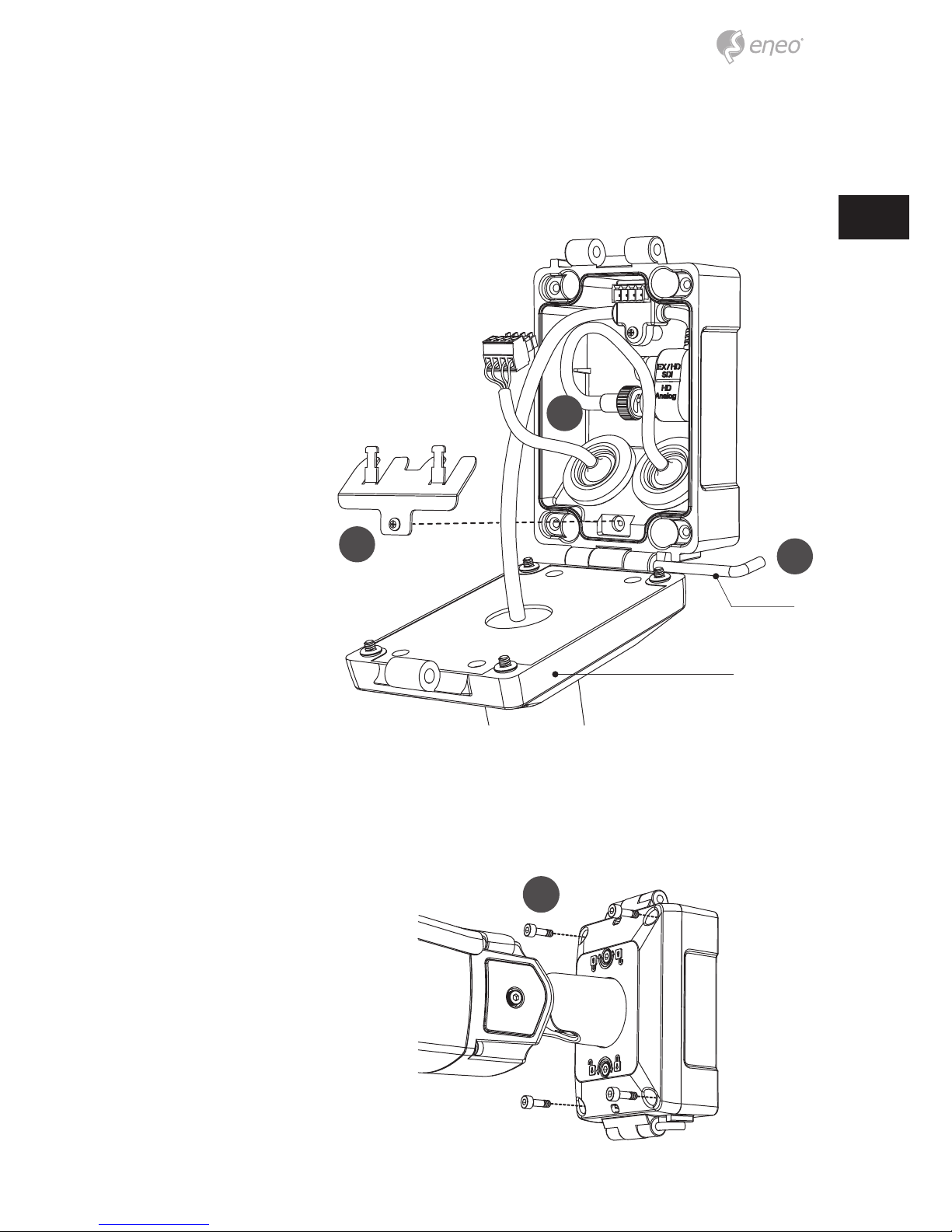
5. Fix the cable xation plate and tie up cable to it.
4
Install the mount onto a strong structure.
Prepare the Junction box base and the accessaries for installation.
1. Locate the mounting template at the installation position and drill the ceiling
or wall if needed.
2. Route the Power/Video cables through the grommets from the wall. Insert
the grommets onto the Junction box base.
3. Place the Junction box base on pre-drilled position and x it through using
mounting screws (4x30mm).
9
EN
6
5
6. Hook up the Junction box top with the Junction box base by the hinge pin.
7. Connects the Power/Video cables from camera as illustrated. Fix the Power/Video
cables from camera to junction box base using the supplied screw.
8. Cover the Junction box top and tighten assembly screws. (4pcs)
7
* Caution: If assembly screws are not rmly assembled, it causes water leakage.
Hinge pin
Junction Box Top
8
 Loading...