

Eneo FNR-4016/500 User Manual
User Manual
Network Video Recorder, 16 IP-Channels, H.264
FNR-4016/500

1
Safety Instructions / Maintenance
• Read these safety instructions and the operation manual first before you install and commission the unit.
• Keep the manual in a safe place for later reference.
• The system may only be commissioned and maintained by personnel authorized to do this and it must only be carried
out in accordance with relevant standards and guidelines.
• Never cover the ventilation slots to avoid overheating.
• Never insert metal objects or any other items into the vents. This may permanently damage the unit.
• Protect your unit from contamination with water and humidity to prevent it from permanent damage. Never switch
the unit on when it gets wet.
Have it checked at an authorized service center in this case.
• Never operate the units outside of the specifications as this may prevent their functioning.
• Do not operate the unit beyond their specified temperature, humidity or power ratings. Operate the unit only at a
temperature range of –10°C to +40°C and at a humidity of max. 80%.
• The unit should be protected against excessive heat, dust, damp and vibration.
• Do not place any heavy objects on the unit.
• To disconnect the power cord of the unit, pull it out by the plug. Never pull the cord itself.
• Pay attention when laying the connection cable and obs erve that the cable is not subject to heavy lo ads, kinks, or
damage and no moisture can get in.
Do not attempt to disassemble the camera board from the dome.
• Contact your local dealer in case of malfunction.
• The connection cable should only be changed by Videor E. Hartig GmbH.
• The warranty becomes void if repairs are undertaken by unauthorized persons. Do not open the housing.
• Installation, maintenance and repair have to be carried out only by authorized service centers.
Before opening the cover disconnect the unit from mains input.
• Only use original parts and original accessories from Videor E. Hartig GmbH.
• Do not use strong or abrasive detergents when cleaning the dome. Use a dry cloth to clean the dome surface. In case
the dirt is hard to remove, use a mild detergent and wipe gently.
NOTE:
This is a class A digital device.
This digital device can cause harmful interference in a residential area; in this case the user may be required to
take appropriate corrective action at his/her own expense.

2
TABL EOFCONTENTS
C H A P T E R 1..................................................................................................................................4
Introduction...........................................................................................................................................4
1.1Front Panel Introduction................................................................................... .........................5
1.2 Starting and Shutting Down Your NVR ....................................................................................6
C H A P T E R 2..................................................................................................................................7
Network Parameters Configuration....................................................................................................7
2.1 Hyper Terminal Setup...............................................................................................................8
2.2 Network Configuration by Hyper Terminal............................................................................11
C H A P T E R 3................................................................................................................................12
ActiveX Control Installation..............................................................................................................12
C H A P T E R 4................................................................................................................................14
User Login and Exit............................................................................................................................14
C H A P T E R 5................................................................................................................................16
Preview.................................................................................................................................................16
5.1 Preview ...................................................................................................................................17
5.1.1 Windows Division........................................................................................................17
5.1.2 Preview.........................................................................................................................18
5.1.3 Preview Control...........................................................................................................18
5.1.4 Stop Preview................................................................................................................19
5.2 Recording and Capturing Image .............................................................................................19
5.2.1 Recording.....................................................................................................................19
5.2.2 Capturing Image...........................................................................................................20
5.3 Vi deo Parameters Setting........................................................................................................20
C H A P T E R 6................................................................................................................................21
PTZ Control.........................................................................................................................................21
C H A P T E R 7................................................................................................................................23
Playback...............................................................................................................................................23
7.1 Playback Query.......................................................................................................................25
7.2 Play Recording File.................................................................................................................25
7.3 Capturing Image and Download .............................................................................................26
7.4 Remote Backup.......................................................................................................................27
C H A P T E R 8................................................................................................................................28
Log Search...........................................................................................................................................28
C H A P T E R 9................................................................................................................................30
Configuration ......................................................................................................................................30
9.1 Local Configuration................................................................................................................31
9.2 IP Camera Configuration ........................................................................................................32
9.2.1 Quick Add of IP camera...............................................................................................33
9.2.2 Single Add of IP camera...............................................................................................33
9.3 Recording Settings..................................................................................................................35
9.3.1 V ideo Parameters ............................................................... .............. ......... ............... ....36
9.3.2 Schedule Recording.....................................................................................................36
9.3.3 Motion Detection Recording........................................................................................38
9.3.4 Alarm Recording............................................. ........................................... ..................40
9.3.5 Other Recording Modes...............................................................................................42
9.4 Alarm Settings..................................................................... ........................................ ............42
9.4.1 Motion Detection Alarm ..............................................................................................42
9.4.2 Signal Level Alarm ......................................................................................................43
9.4.3 V ideo Loss....................................................... .............. .............. .......... .............. .........44
9.4.4 V ideo Tampering................................................................ .............. .......... .............. ....45

3
9.4.5 Exceptions....................................................................................................................46
9.5 Network Configuration...........................................................................................................47
9.5.1 Basic Configuration.....................................................................................................47
9.5.2 PPPoE Settings.............................................................................................................48
9.5.3 DDNS Settings .............................................................................................................48
9.5.4 NTP Settings ................................................................................................................48
9.5.5 Net Disk Settings .........................................................................................................49
9.5.6 E-Mail Settings ............................................................................................................49
9.6 Channel Configuration ............................................................................................................50
9.6.1 Channel Display Settings.............................................................................................50
9.6.2 V ideo Mask...................................... ............... ......... ............... ......... .............. ..............50
9.7 Account Management ................................. ................................................ ............................51
9.8 Remote Upgrade .....................................................................................................................52
9.9 HDD Settings..........................................................................................................................53
C H A P T E R 10..............................................................................................................................55
Appendix..............................................................................................................................................55
Glossary .......................................................................................................................................56
FAQ ..............................................................................................................................................57
Specifications...............................................................................................................................58

4
C H A P T E R 1
Introduction

5
1.1Front Panel Introduction
FNR-4016/500 Front Panel:
No.
Name
Description
Power
Turning red indicates power supply but without system running, turning blue
indicates power supply and system running.
Alarm Alarm indicator turns red when a sensor alarm is detected.
TX/RX TX/RX indictor blinks blue when network connection is functioning properly.
HDD HDD indicator blinks red when data is being read from or written to HDD.
Ready Ready indicator turns blue when NVR is functioning properly.
1
Status
LED
Indicators
Backup Backup indicator blinks blue when data is being backup.
2 Backup Button Backup video files.
3 USB Ports
Universal Serial Bus (USB) ports for additional devices such as USB mouse and
USB Hard Disk Drive (HDD).
4 Power Button Powers NVR on/off.
5
Channel Status
Indicators
Blue indicates recording, red indicates network connection, purple indicates
recording & network connection.

6
1.2 Starting and Shutting Down Your NVR
Power On
If the power LED indicator on the front panel is off, please plug the power supply into an electrical outlet, the LED
should turn red, indicating the unit is receiving power.
When the LED is red, please press the Power button on the front panel. The Power indicator will turn blue. The unit
will begin to start.
Note: The FNR-4016/500 doesn’t have local output, when Ready indicator turns blue, that means the unit is power
on and ready to be configured.
Power Off
Standard Shutdown
Press and hold the POWER button for 3 seconds; the device will enter power off process, when power indicator turns
red, turn off the power switch on the back panel.
Other Methods of Shutdown
Shutdown with Power Switch
Please try to avoid shutting down the unit by turn off the power switch on the back panel (especially during recording).
Shutdown by Unplug Power Supply
Please try to avoid shutting down the unit by unplug power supply (especially during recording).
Note: It is highly recommended that an Uninterruptible Power Supply (UPS) be used in conjunction with the unit.

7
C H A P T E R 2
NetworkParametersConfiguration
8
The FNR-4016/500 NVR is mainly for IPC, DVS network video storage and playback. Network configurations are
needed before operating, including: IP address, subnet mask, gateway and port.
Note: The factory default username is admin, password is 12345.
The factory default IP address of the FNR-4016/500 is 192.168.0.1.
2.1 Hyper Terminal Setup
The common method is to connect NVR and PC with serial line, run Hyper Terminal and modify parameters with serial
command. Please connect the RS-232 port of NVR with the COM port of PC directly, power on the NVR and PC and
follow the steps:
Step 1: Enter Hy per Terminal.
Click “Start”-> “Programs” -> “Accessories” -> “Communications” -> “Hyper Terminal” in Windows system, and the
dialogue box below will appears as Figure 2.1.1.
Figure 2.1.1
9
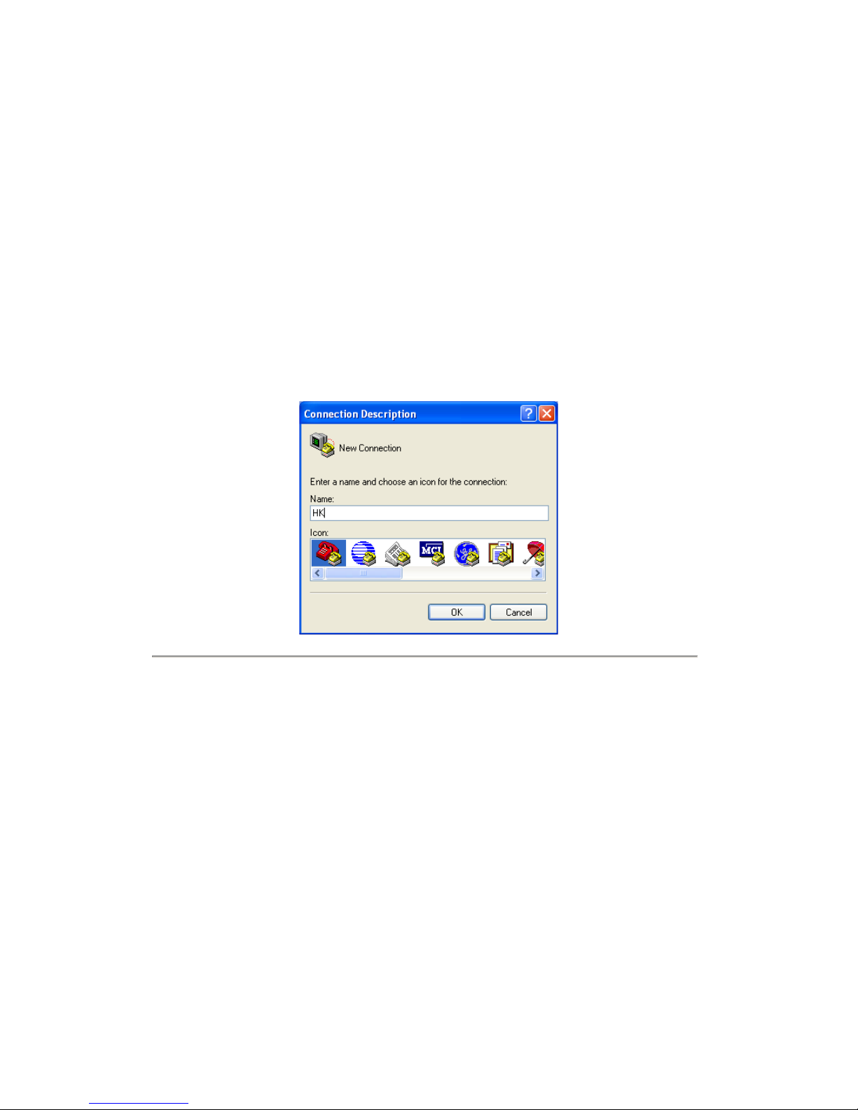
Step 2: Name the connection and define the icon.
Input a name (e.g. HK), select an icon, and press “OK” to enter “Connect To” dialogue box.
Step 3: Select the communication port.
Select “COM1” in “Connect To” inter face (Please select the COM port according to the reality, in case PC has more
than 1 COM.) Press “OK” to enter “Properties” dialogue box.
Figure 2.1.2
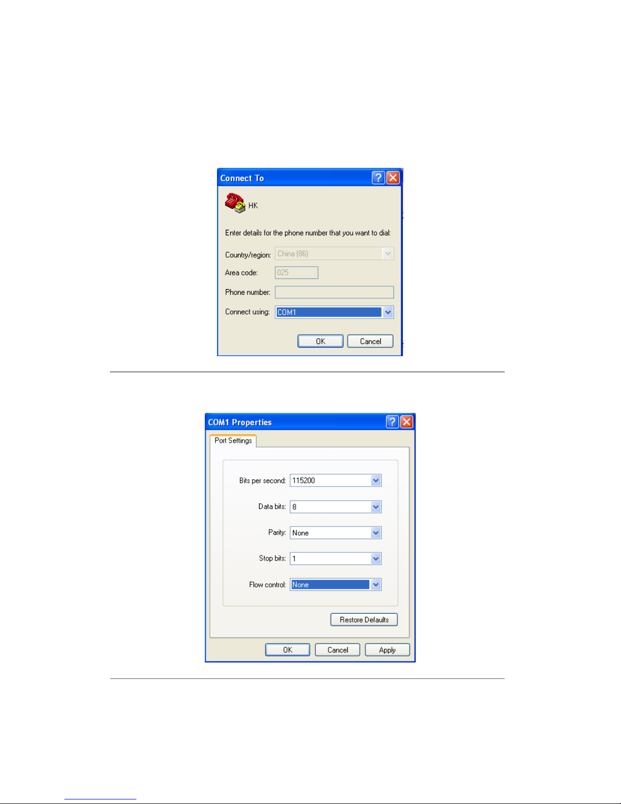
Step 4: Serial port setup.
Set port parameters in “COM1 Properties” dialogue box as follow: (Fig 2.1.3)
Figure 2.1.3
10
The parameters should be:
Bits per second: 115200
Data bits: 8
Parity: None
Stop bits: 1
Flow control: None
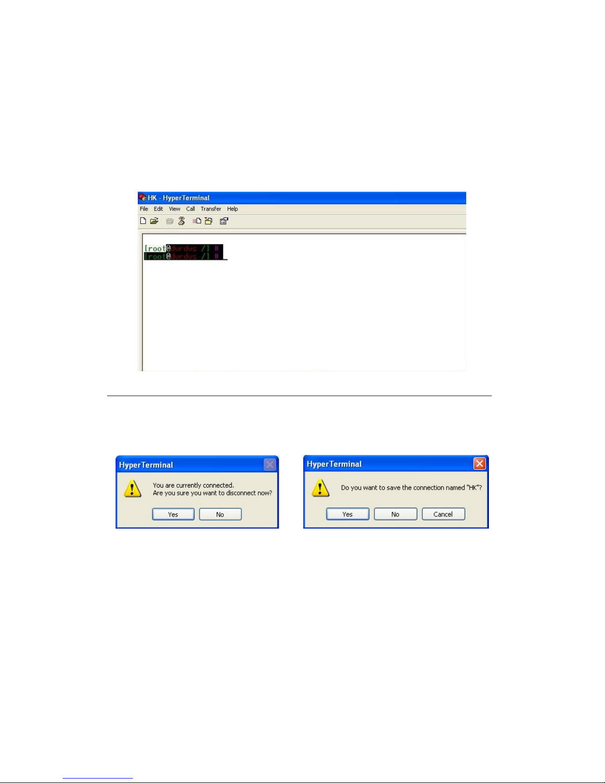
Press “Apply” and “OK” after the setup. Press “Enter” under Hyper Terminal interface. When “[root@dvrdvs/]#”
appears, the connection is established.
Figure 2.1.4
Step 5: Disconnect and save connection.
According to the tips, disconnect and save “HK” for the next time. After saving, there will be a new “Hyper Terminal”
item established in the program group “Start”-> “Accessories”->“Communications”->“Hyper Terminal”. “Connection”
names of all Hyper Terminal are included. You can see an icon named as “HK” here.
11
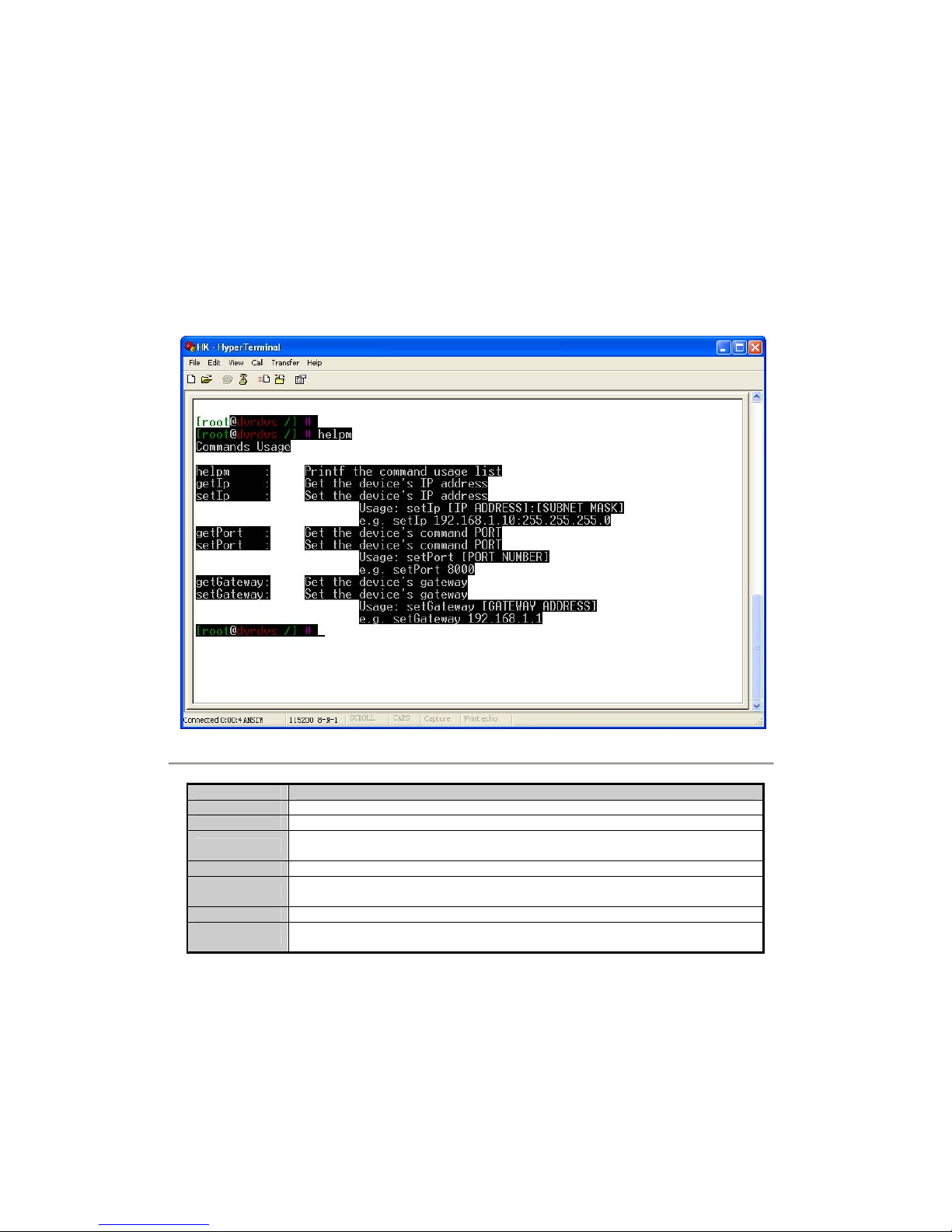
2.2 Network Configuration by Hyper Terminal
Enter Hyper Terminal
Click “Start”->“Programs”->“Accessories”->“Communications”->“Hyper Terminal”->“HK”, then the Hyper Terminal
interface will appear as figure below. Type “Enter”, and the prompt “[root@dvrdvs/]#” will appear which means
connection between RS232 interface of PC and RS232 interface of NVR is established successfully by Hyper Terminal.
The following operation commands are to accomplish the parameters setup in the prompt.
Figure 2.2.1
Commands Utilities
helpm Console help command is used to print common commands, show as Figure 2.2.1.
getIp Show the current IP address of NVR. Command format: getIp “Enter”.
setIp
Setup NVR IP address. Command format: setIp IP: mask
e.g. setIp 192..168.1.11:255.255.255.0
getPort Show the current port of NVR. Command format: getPort “Enter”.
setPort
Setup NVR port. Command format: setPort Port
e.g. setPort 9000
getGateway Show current NVR gateway address. Command format: getGateway “Enter”.
setGateway
Setup NVR gateway. Command format: setGateway Gateway
e.g. setGateway 192.168.1.1

12
C H A P T E R 3
ActiveXControlInstallation

13
The FNR-4016/500 can be accessed and configured by web server. Open IE browser, input the IP address of the
FNR-4016/500 and then click Enter. The system will remind you to install the ActiveX control. After the installation,
you can configure and manage the NVR remotely.
The ActiveX control has English and Chinese to selections. It can be used under 1024*768, 1152*864, 1280*1024
display resolutions.
Note: Please use IE 6.0 or IE 7.0 as browser, and upgrade OS to the latest version.

14
C H A P T E R 4
UserLoginandExit
15
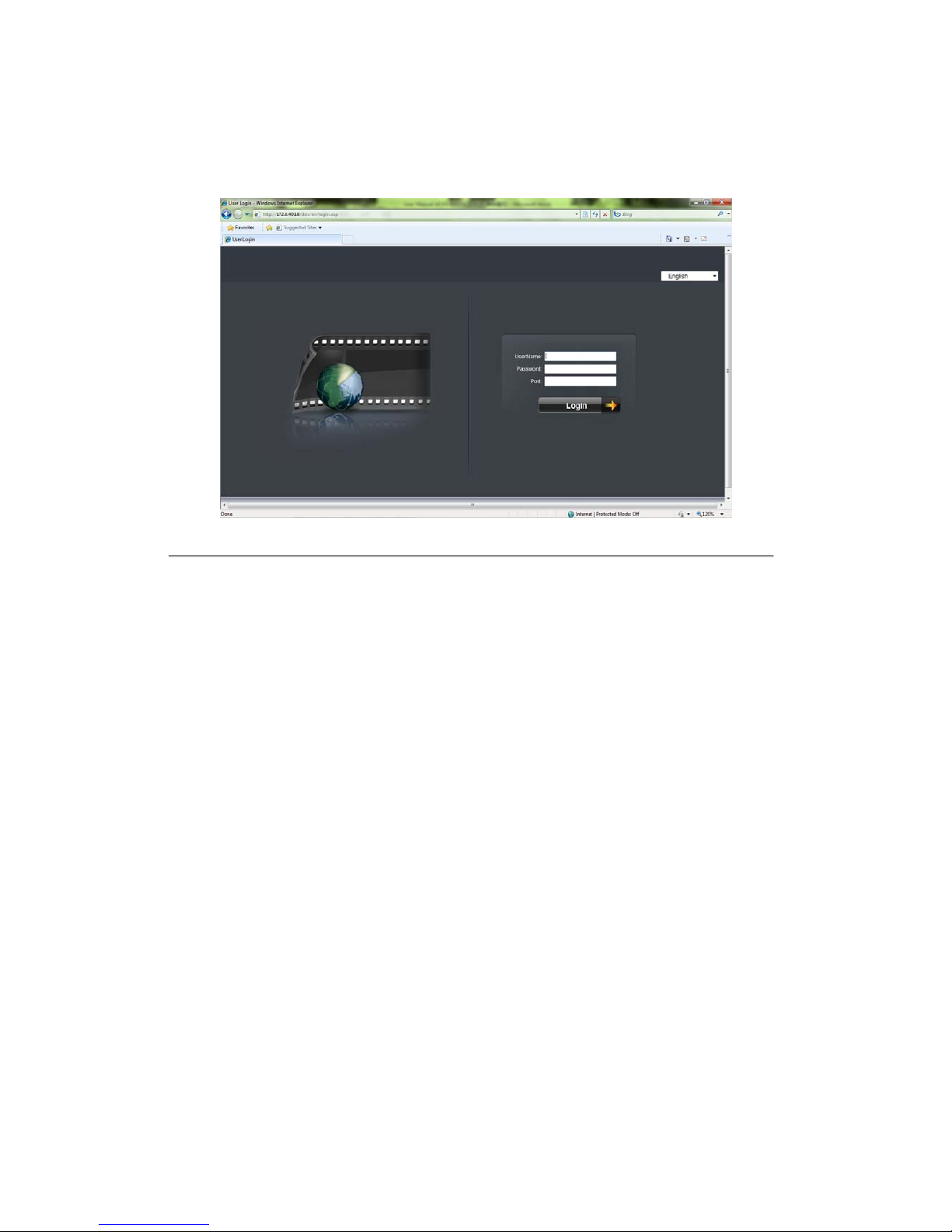
Open IE browser, input the IP address of NVR, the web server will select the language automatically according to the
system language and maximize the IE browser.
Figure 4.1
On the top right corner, language is selectable between Chinese and English.
Input the correct user name, password and port, click “Login” to enter preview interface, or it will pop up an error box.
The default user name is admin, password is 12345, and port is 8000.
After login, click “Exit” to log off and return to the login interface.

16
C H A P T E R 5
Preview
17
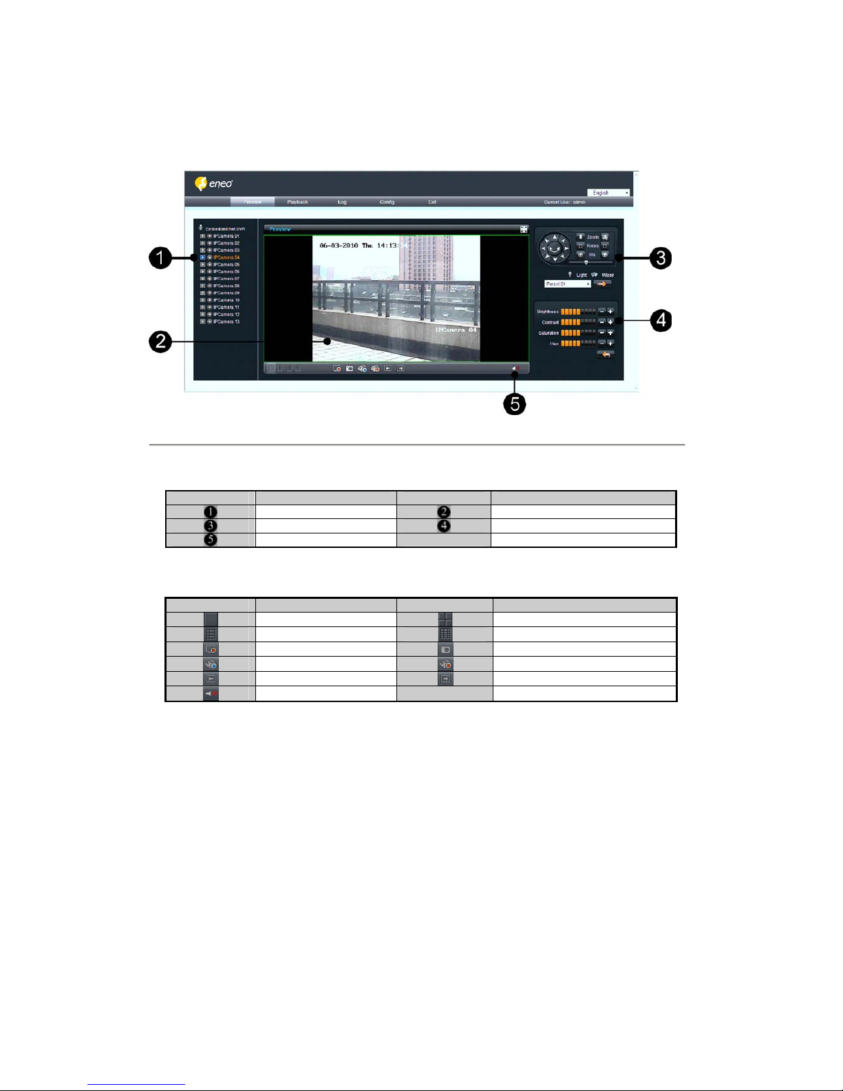
After login, the preview interface will display:
Figure 5.1
Interface description:
Area Description Area Description
Channel list
Live view
PTZ
Video adjustment
Play control
Play control buttons description:
Button Description Button Description
1 window division
4 windows division
9 windows division
16 windows division
Stop all preview
Capture image
Start all recording
Stop all recording
Previous page
Next page
Open/ Close audio
5.1 Preview
5.1.1WindowsDivision
When live preview, the windows division can be selected by click the button on play control area. It can support 1, 4, 9
and 16 windows division. The change between different windows division modes will not stop the current preview; the
window still can be operated.
 Loading...