

Eneo EPS-1016 Full Manual

Full Manual
PoE Switch, 16 Ports 10/100Base-TX,
PoE+, RJ45 and SFP Gigabit Uplink, 250W
EPS-1016

FCC Warning
This Equipment has been tested and found to comply with the limits for a Class-A
digital device, pursuant to Part 15 of the FCC rules. These limits are designed to
provide reasonable pr o t ecti on against harmful inter f erence in a residential i ns t al l ati on .
This equipment generates, uses, and can radiate radio frequency energy. It may
cause harmful interference to radio communications if the equipment is not installed
and used in accordance with the instructions. However, there is no guarantee that
interference will not occur in a particular installation. If this equipment does cause
harmful interference to radio or television reception, which can be determined by
turning the equipment off and on, the user is encouraged to try to correct the
interference by one or more of the following measures:
Reorient or relocate the receiving antenna.
Increase the separation between the equipment and receiver.
Connect the equipment into an outlet on a circuit different from that to which the
receiver is connected.
Consult the dealer or an experienced radio/TV technician for help.
CE Mark Warning
This is a Class-A product. In a domestic environment this product may cause radio
interference in which case the user may be required to take adequate measures.

Content
Content 1
Introduction 2
Hardware Description 5
User Log In 7
Administrator 8
Port Management 13
VLAN Setting 17
Per Port Counter 21
QoS Setting 22
Security 24
Spanning T ree 26
Trunking 29
Backup/Recovery 30
Miscellaneous (IGMP) 31
Logout 32
1

Introduction
Product Overview
This switch provides 16 10/100Mbps RJ-45 ports and can support 2 Combo
Gigabit RJ-45/SFP to uplink. This web-smart switch includes auto-MDI/MDIX
crossover detection function. 16 of those ports are all built with PoE
functionality, pr ov iding the ulti mate ch oice in netw or k flexi bili ty . With thi s adde d
PoE feature, this switch is an ideal solution for building wireless, IP
surveillance, and VoIP networks.
It also provides port-based and 802.1Q tag VLAN function to provide better
traffic management, reduces latency, improve security and save bandwidth.
This is also a cost-saving feature as it reduces the need to add additional
hardware to the network.
These 16 10/100Mbps RJ-45 support the IEEE 802.3at PoE protocol. Each
port and transmit a maximum power 30 watts. User can also enable or disable
power supply on PoE ports from UI.
Web Management Features
Port Management
Port Configuration
Port Mirroring
Bandwidth Control
Broadcast Strom Control
PoE On/Off Setting
VLAN Setting
Port-based/ Tag-based
VLAN ID: 1~4094
Trunking
Link Aggregati on Setti ng
2 groups (1~4 port for each group)
QoS Setting
Priority Mode
Class of Service Configuration
TCP/UDP Port-based
Security Setting
2

MAC address filtering
TCP/UDP Port filtering
STP/RSTP
Spanning T ree Protoco l
Backup Recovery Configuration
Specifications
Standard
IEEE 802.3 10BaseT
IEEE 802.3u 100BaseTX
IEEE 802.3x Full-duplex and Flow Control
IEEE 802.af PoE
IEEE 802.at PoE
IEEE 802.3ad Link Ag gregation
IEEE 802.1d Spanning tree protocol
IEEE 802.1w Rapid Spanning tree protocol
IEEE 802.1x Port-based Network Access Control
IEEE 802.1Q VLAN
IEEE 802.1p Class of Serv i ce
Number of Port
16-port 10/100BaseTX with PoE
2-port Combo Gigabit uplink (RJ-45/SFP)
Mechanical
LED Indicator
Per Port: Link/ Act
PoE Por t: Act/Status
Per Unit: Power
Power Consumption: 250Watts (Max)
Power Input: 100~240V/AC, 50~60HZ
Power Output: 48V/DC per Port Output – 30W Max per Port
Product Dimensions/ We i g h t
44 × 440 × 220 mm (H × W ×D) / 3.0kg
3
Performance
MAC Address: 4K
Buffer Memory: 2.75Mb
Trans miss i on Me tho d: St or e and Forward
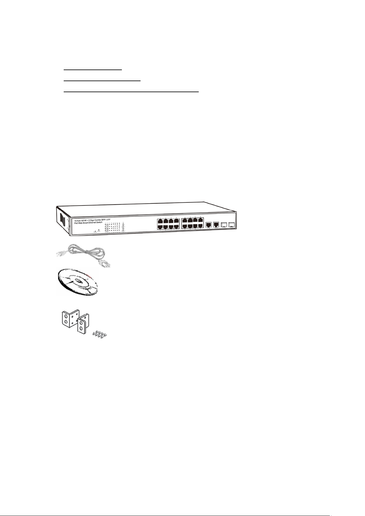
Package Contents
Before you start to install this switch, please verify your package that
contains the following items:
One Fast Ethernet PoE Switch
One EU Power Cord
A User Manual CD
Rack-mount kit
4
Hardware Description
LED
Status
Description
No. Of LED
Power
On
Power on
Power
On
Link 1000Mbps
off
Link 10/100Mbps
On
Link
18 (1~18)
Flashing
Data activating
18 (1~18)
Port is linked to Power
Device
No Power Device is
connected
RJ-45 Port
This section mainly describes the hardware of the 8 PoE port Ethernet Combo
Web-Smart Switch and gives a physical and functional overview on the certain
switch.
Physical Dimensions/ Weight
44 × 440 × 220 mm (H × W ×D) / 3.0kg
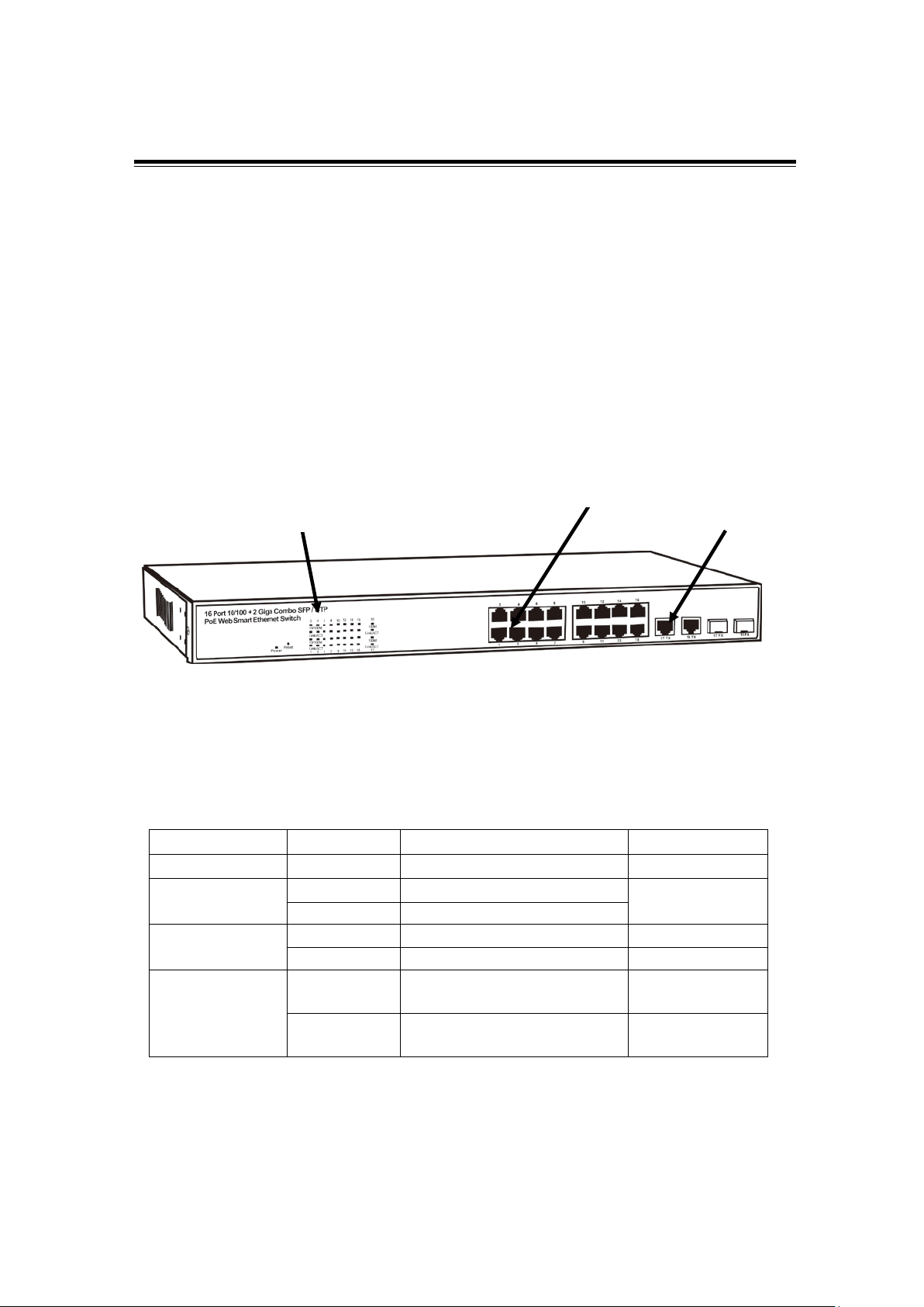
Front Panel
The front panel of the web smart switch consists of 16 10/100Base-TX RJ-45
ports and 2 combo gigabit uplink RJ-45/SFP ports. The LED Indicators are
also located on the front panel.
LED
Display
Combo Uplink
RJ-45/SFP Port
LED Indicators
The LED Indicators present real-time information of systematic operation
status. The following table provides description of LED status and their
meaning.
1000M
2 (17~18)
Link/ ACT
PoE
On
Off
16 (1~16)
16 (1~16)
5

Rear Panel
The 3-pronged power plug is placed at the rear panel of the switch right side
shown as below.
Hardware Installation
Set the switch on a large flat space with a power socket close by. The flat
space should be clean, smooth, level and sturdy. Make sure there is enough
clearance around the switch to allow attachment of cables, power cord and
allow air circulation. The last, use twisted pair cable to connect this switch to
your PC then user could start to operate the switch.
6
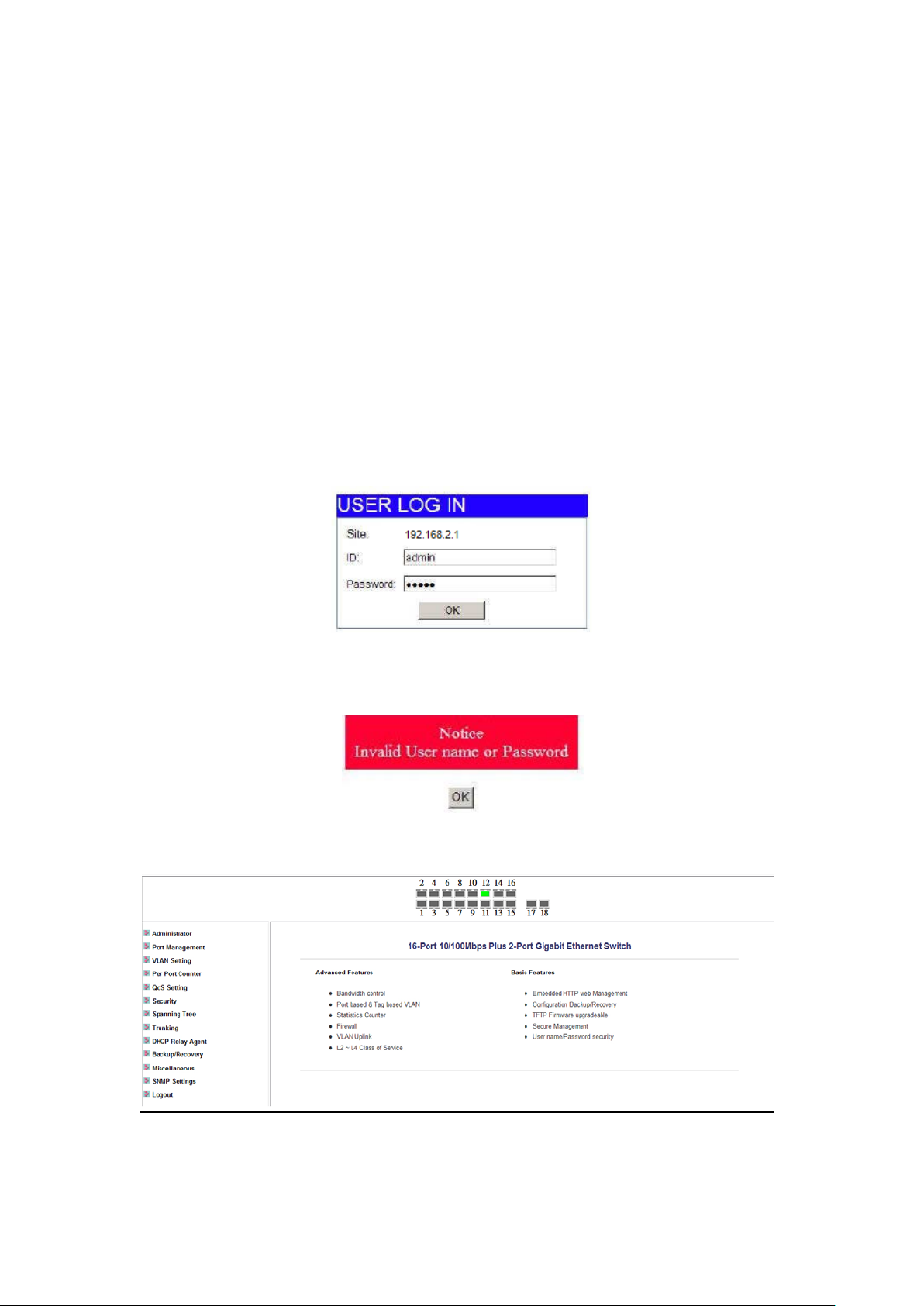
User Log In
This part instructs user how to set up and manage the switch through the web
user interface. Please follow the description to understand the procedure.
At the first, open th e w eb br owser, and go to 192. 168 . 2. 1 s it e the n the user will
see the login screen. Key in the password to pass the authentication then
clicks the OK. The log in process is completed and comes out the sign
“Password successfully entered”.
Log in
ID: admin
Password: admin
Figure 1-1
※Note: It will show error message if you key i n wrong user name or pas sword.
Figure 1-2
Main Page
Figure 1-3
7
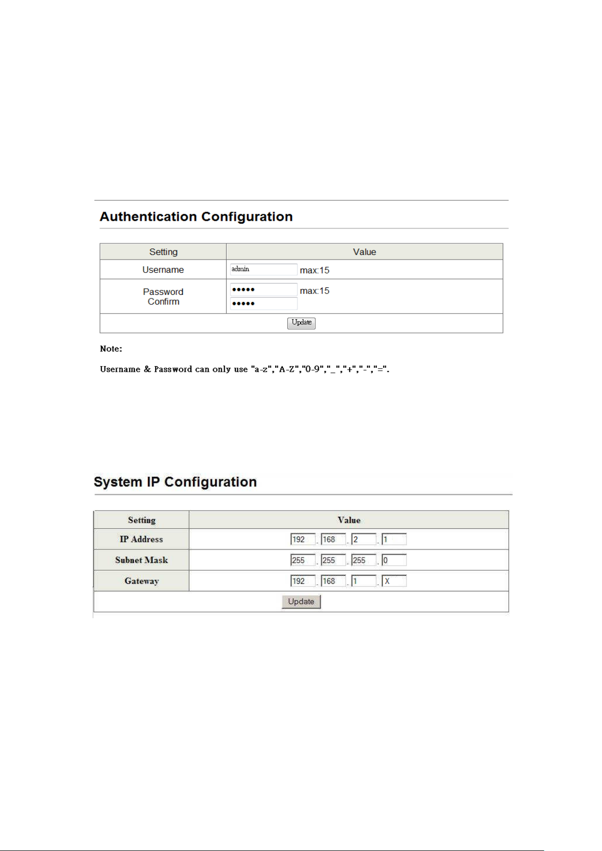
Administrator
Authentication Configuration
This page shows authentication configuration information. User can set new
Username and Password in this page.
Figure 2-1
System IP Configuration
This page shows system configuration including the current IP address and
sub-net mask and gateway.
Figure 2-2
User can configure the IP settings, Subnet Mask, Gateway as below:
IP address: Manually assign the IP address that the network is us ing. The
default IP is 192.168.2.1
Subnet Mask: Assign the subnet mask to the IP address.
Gateway: Assign the network gateway for industrial switch.
If you change the IP address of this switch and then press Update. It will show
8
“update successfully” then press Reboot button. It will enter user login
screen automatically
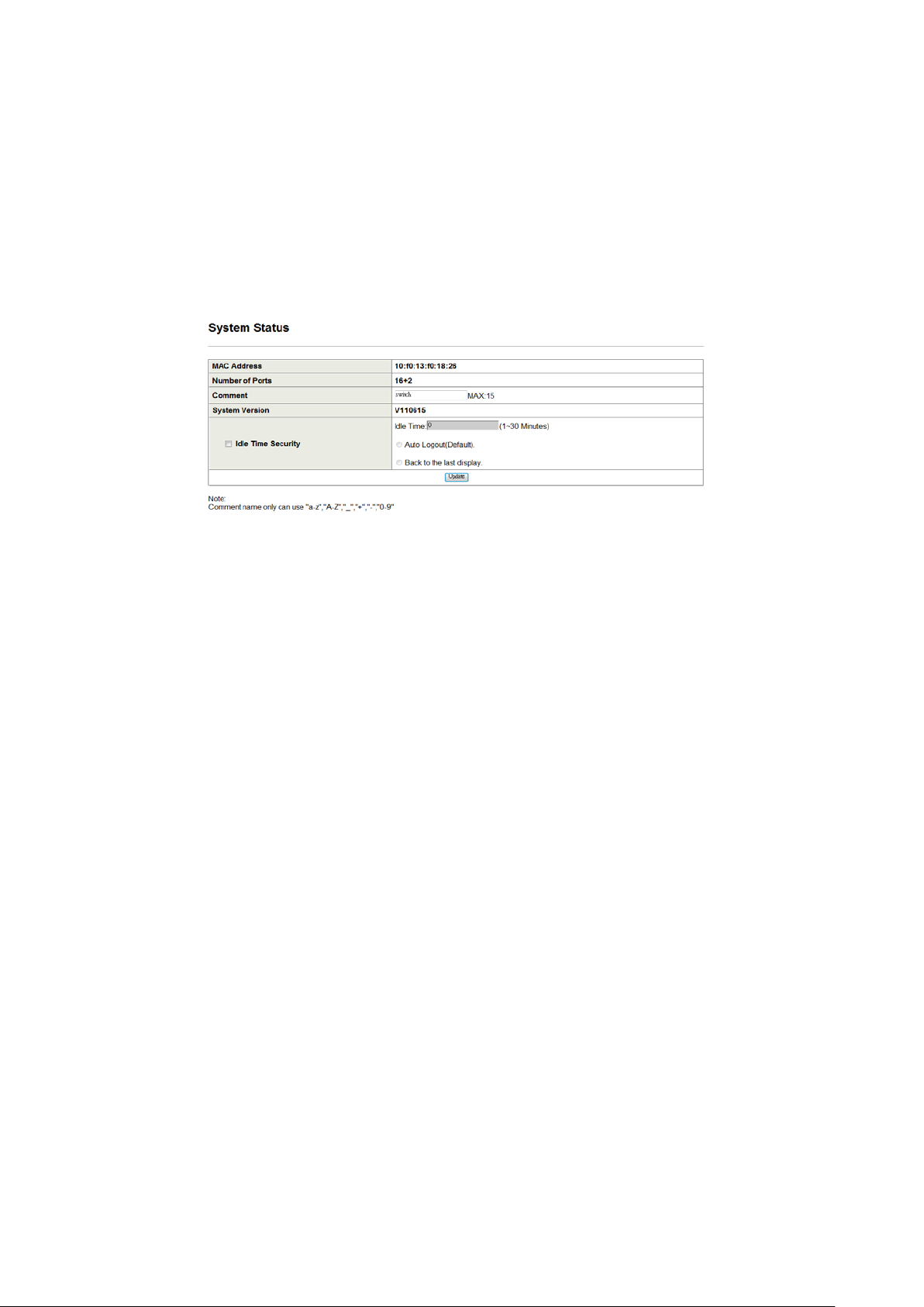
System Status
This page displays the information about the switch of MAC address, how
many ports it has, system version and. Besides, users can also fill in up to 15
characters in the Comment, Contact and Location field for note.
Figure 2-3
MAC Address: Displays the unique hardware address assigned by
manufacturer (default).
Number of Ports: Displays number of ports in the switch.
System Version: Displays the switch’s firmware version.
Idle Time Security: User can set the time security. When user leave the
computer for a moment, the software will auto logout or back to the last
display.
And then click Update button.
9
 Loading...