

Eneo EDMC-3221B User Manual

Full Manual
Fastrax I**
1/4“ Day/Night Dome Camera, PTZ
EDC-xx
WARNING
TO REDUCE THE RISK OF FIRE OR ELECTRIC SHOCK, DO
NOT EXPOSE THIS PRODUCT TO RAIN OR MOISTURE. DO
NOT INSERT ANY METALLIC OBJECTS THROUGH THE
VENTILATION GRILLS OR OTHER OPENINGS ON THE
EQUIPMENT.
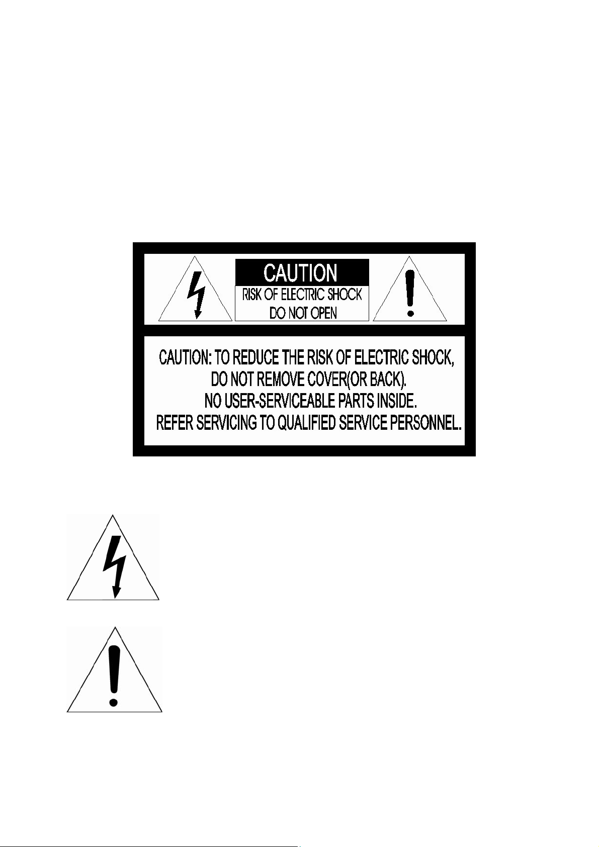
CAUTION
EXPLANATION OF GRAPHICAL SYMBOLS
The lightning flash with arrowhead symbol, within an
equilateral triangle, is intended to alert the user to
the presence of uninsulated “dangerous voltage”
within the product’s enclosure that may be of
sufficient magnitude to constitute a risk of electric
shock to persons.
The exclamation point within an equilateral is
intended to alert the user to the presence of
important operating and maintenance (servicing)
instructions in the literature accompanying the
appliance.
II

FCC COMPLIANCE STATEMENT
FCC INFORMATION: This equipment has been tested and found
to comply with the limits for a Class A digital device, pursuant to
Part 15 of the FCC Rules. These limits are designed to provide
reasonable protection against harmful interference when the
equipment is operated in a commercial environment. This
equipment generates, uses, and can radiate radio frequency energy
and, if not installed and used in accordance with the instruction
manual, may cause harmful interference to radio communications.
Operation of this equipment in a residential area is likely to cause
harmful interference in which case the user will be required to
correct the interference at his own expense.
CAUTION: Changes or modifications not expressly approved by
the party responsible for compliance could void the user’s authority
to operate the equipment.
This Class A digital apparatus complies with Canadian ICES-003.
Cet appareil numérique de la classe A est conforme à la norme
NMB-003 du Canada.
CE COMPLIANCE STATEMENT
WARNING
This is a Class A product. In a domestic environment this product
may cause radio interference in which case the user may be
required to take adequate measures.
III

IMPORTANT SAFETY INSTRUCTIONS
1. Read these instructions.
2. Keep these instructions.
3. Heed all warnings.
4. Follow all instructions.
5. Do not use this apparatus near water.
6. Clean only with dry cloth.
7. Do not block any ventilation openings. Install in accordance with the
manufacturer’s instructions.
8. Do not install near any heat sources such as radiators, heat registers,
stoves, or other apparatus (including amplifiers) that produce heat.
9. Do not defeat the safety purpose of the polarized or grounding-type
plug. A polarized plug has two blades with one wider than the other. A
grounding type plug has two blades and a third grounding prong. The
wide blade or the third prong are provided for your safety. If the
provided plug does not fit into your outlet, consult an electrician for
replacement of the obsolete outlet.
10. Protect the power cord from being walked on or pinched particularly at
plugs, convenience receptacles, and the point where they exit from
the apparatus.
11. Only use attachments/accessories specified by the manufacturer.
12. Use only with the cart, stand, tripod, bracket, or table
specified by the manufacturer, or sold with the
apparatus. When a cart is used, use caution when
moving the cart/apparatus combination to avoid injury
from tip-over.
13. Unplug this apparatus during lightning storms or
when unused for long periods of time.
14. Refer all servicing to qualified service personnel. Servicing is required
when the apparatus has been damaged in any way, such as powersupply cord or plug is damaged, liquid has been moisture, does not
operate normally, or has been dropped.
15. CAUTION – THESE SERVICING INSTRUCTIONS ARE FOR USE
BY QUALIFIED SERVICE PERSONNEL ONLY. TO REDUCE THE
RISK OF ELECTRIC SHOCK DO NOT PERFORM ANY SERVICING
OTHER THAN THAT CONTAINED IN THE OPERATING
INSTRUCTIONS UNLESS YOU QRE QUALIFIED TO DO SO.
16. Use Certified/Listed Class 2 power source only.
17. Apparatus shall not be exposed to dripping or splashing and no object
filled with liquids, such as vases, shall be placed on the apparatus.
IV

Table of Contents
Chapter 1 — Introduction ..........................................................................................................1
1.1 Features .............................................................................................................................................1
Chapter 2 — Installation and Configuration.........................................................................2
2.1 Package Contents............................................................................................................................2
2.2 Installation.........................................................................................................................................3
2.3 Basic Configuration of Dome Camera System........................................................................6
2.4 Setting Dome Camera Termination.............................................................................................7
2.5 Setting Dome Camera Address (ID)............................................................................................7
2.6 Setting Dome Camera Protocol and Video.............................................................................14
2.7 Connections....................................................................................................................................14
2.8 Getting Started...............................................................................................................................15
Chapter 3 — Program and Operation...................................................................................16
3.1 Dome Camera Selection ..............................................................................................................16
3.2 Accessing the On-Screen Menu Utility....................................................................................16
3.3 How to control the On-Screen Menu Utility............................................................................17
3.4 Auto Scan (Shortcut: SCAN ) ...................................................................................................... 17
3.5 Preset (Shortcut: PRST) ..............................................................................................................19
3.6 Shortcut of Preset Program........................................................................................................21
3.7 Tour (Shortcut: TOUR).................................................................................................................21
3.8 Pattern (Shortcut: PTRN) ............................................................................................................23
3.9 Alarm.................................................................................................................................................24
3.10 Area Title........................................................................................................................................24
3.11 Privacy Zone.................................................................................................................................25
3.12 Camera Menu................................................................................................................................26
3.13 Dome Setup ..................................................................................................................................29
3.14 Function Run................................................................................................................................35
3.15 Factory Setup...............................................................................................................................36
Appendix A — Specifications.................................................................................................37
Appendix B — Troubleshooting ............................................................................................39
Appendix C — Glossary...........................................................................................................39
Appendix D — Short Cut Key .................................................................................................42
V

Chapter 1 — Introduction
1.1 Features
The dome camera and the keyboard controller make up the building blocks for any
surveillance/security system. Using multiple keyboard controllers and multiple dome cameras, no
place is too large for monitoring. Extensible and flexible architecture facilitates remote control
functions for a variety of external switching devices such as multiplexers and DVRs.
• Built-in optical power zoom camera with True Night Shot function
• 240 Preset positions with the individual Camera AE setup
• 8 Tours consist of Presets, Patterns, Auto Scans and other Tours can be programmed with
over 300 functions and preset locations. While moving, each Preset scan can be watched in
smooth Vector Scan mode.
• 16 Auto Scans with the normal, the vector, and the random mode and the endless Auto-Pan
with 13 speed steps
• 8 Patterns (up to 200 second) and 8 Privacy Zones
• 16 Area Titles
• 4 Alarm inputs / 1 Alarm output (5VTTL)
• Variable speed from 0.1°/sec to 380°/sec
Three Variable speed (SLOW, NORMAL, TURBO)
Turbo speed is 380°/sec with Ctrl key pressed.
• Pan/Tilt speed is inversely proportional to the zoom ratio with the option.
• Maximum speed is 380°/sec when Preset command.
• Auto Calibration from 0.1° to 6° (Tilt range is 0° to 180°)
• Programmable user preferences (alarm, preset, title, etc.)
• 180° Digital Flip
• Up to 255 selectable camera addresses
• Multi-language Menu Display, Password Confirmation
• Function Run menu using DVR without function key (Pattern, Scan, …)
• Built-in RS-485 receiver driver
• 24VAC or 12VDC for Dome
• Use Certified/Listed Class 2 power source only.
1

Chapter 2 — Installation and Configuration
2.1 Package Contents
The dome camera is designed with a compact, small size, hard dome camera housing.
The housing is constructed of aluminum, steel and plastic. The housing is designed to be
mounted on a wall or a ceiling. The housing meets the Protection Classification IP66 standards
for dust and moisture resistance.
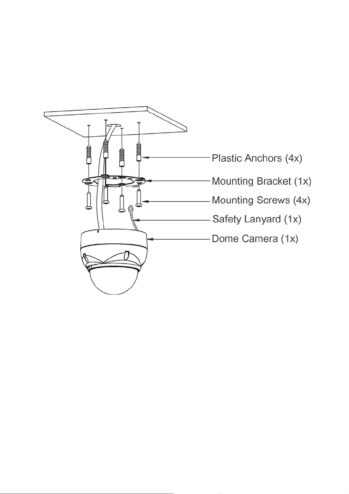
* Dome Camera
* Instruction Manual (This Document)
* Template Sheet
* Mounting Bracket
* Safety Lanyard
* Accessory Kit
1) Mounting screws (PH6 x 35.0)
2) Plastic anchors
3) O-Rings
4) Torx wrench
* Accessory Connector
1) 3-Pin Terminal Block
2) 2-Pin Terminal Block
3) 5-Pin Terminal Block
(4)
(4)
(4)
(1)
(1)
(2)
(1)
1
1
1
1
1
1
1
2
2.2 Installation
The dome camera is for use in surface or pendent mounting applications and the mounting
member must be capable of supporting loads of up to 3.3lb (1.5kg). (Pendent mounting must use
pendent mount accessory.)
The dome camera’s mounting bracket should be attached to a structural object, such as hard
wood, wall stud or ceiling rafter that supports the weight of the dome camera.
CAUTION: A silicone rubber sealant must be applied to seal the housing to secure
waterproofing.
2.2.1 Locking Dome Camera
A. Make screw holes on the ceiling using the supplied mounting Template Sheet (Figure A).
B. Fix the Mounting Bracket to the ceiling using supplied Anchors (4x) and Mounting Screws (4x)
(Figure B).
C. Hook up the Safety Lanyard to the Safety Lanyard Hook of the Mounting Bracket (Figure C).
D. Align the locking tab on the bracket and the locking slot on the base of the dome (Figure D).
E. Turn the dome to the counterclockwise about 10 degree to the locked position (Figure E).
3
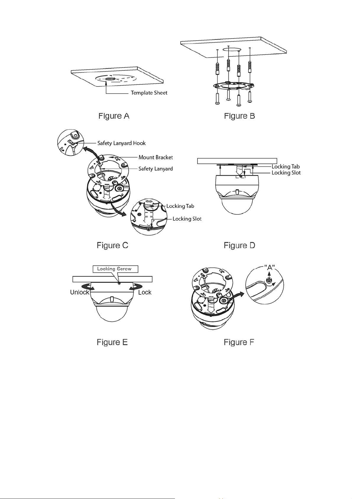
CAUTION 1: Before installing mounting bracket to surface pre-adjust the four mounting
screws "A" on the base of the dome camera to best match the mounting
bracket locked position. Unscrew the locking screw on the side of the dome's
base and fit the tab of the mounting bracket into the locking slot. Screws "A"
should not be too tight or too loose when the dome is in the locked position.
After setting the proper positions of screws "A" remove the mounting bracket
and install it to the proper surface. If it is too difficult to lock the dome in
position after the mounting bracket has been installed readjust the screws "A"
by unscrewing them a small amount and try to install dome camera again.
CAUTION 2: Set the termination and ID address of the dome before final installation as
described at 2.3 (figure 2), 2.4 and 2.5.
4
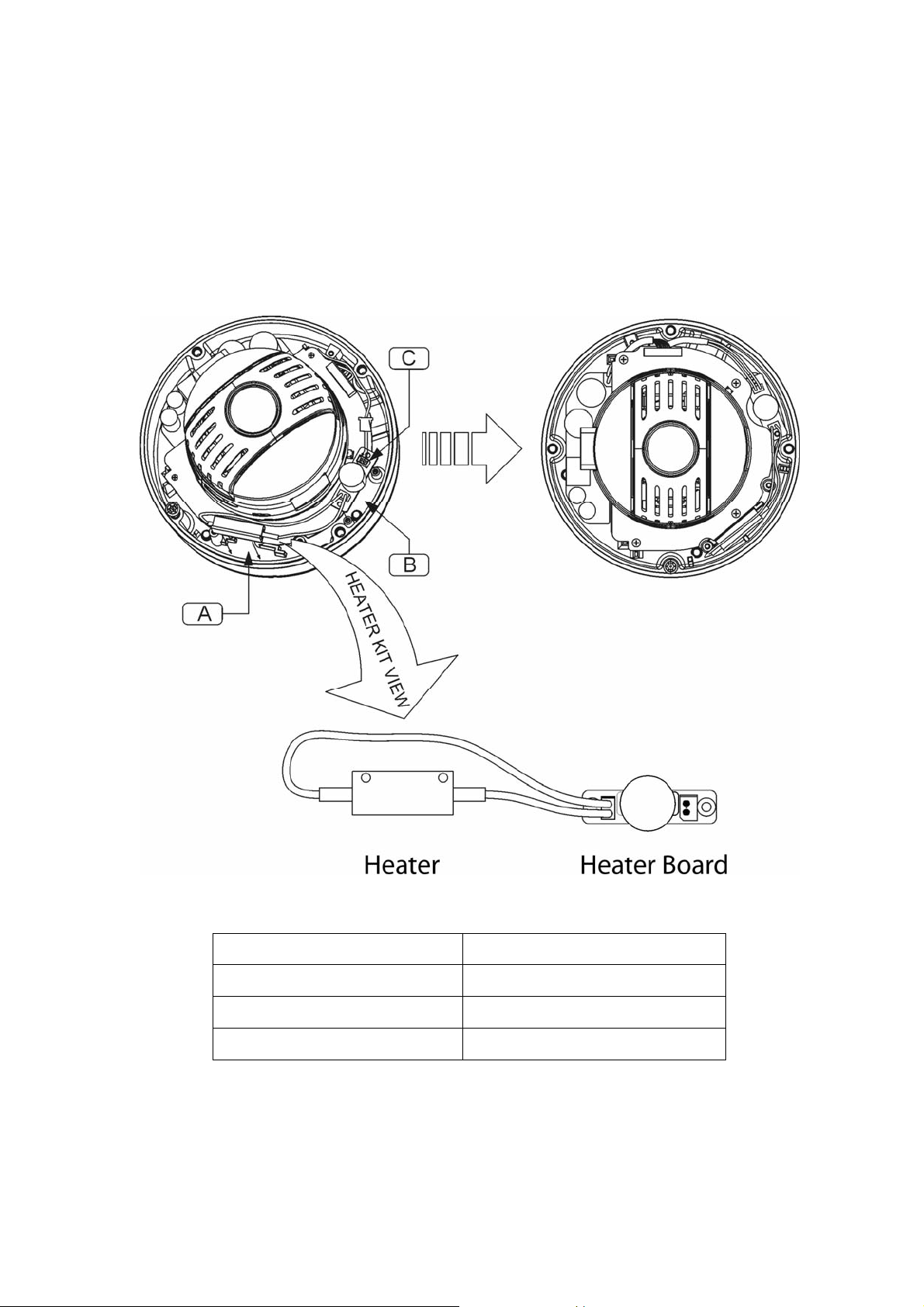
2.2.2 Heater Kit Installation
1. Assemble the Heater board to two bossed with screws.
Take a reference "B" in the bottom case as below.
2. Place the Heater in the slot "A".
Heater cable should be placed away from the Main board.
3. Plug the power connector to the socket "C"(J1) of the Heater board.
4. 24VAC is recommended to use for the camera power for stable operation with heater kit.
• HEATER (IF APPLICABLE)
Power Supply 24VAC
Power Consumption 10W
Heater ON at 59°F (15°C)
Heater OFF at 77°F (25°C)
• POWER
Use Certified/Listed Class 2 power source only.
5
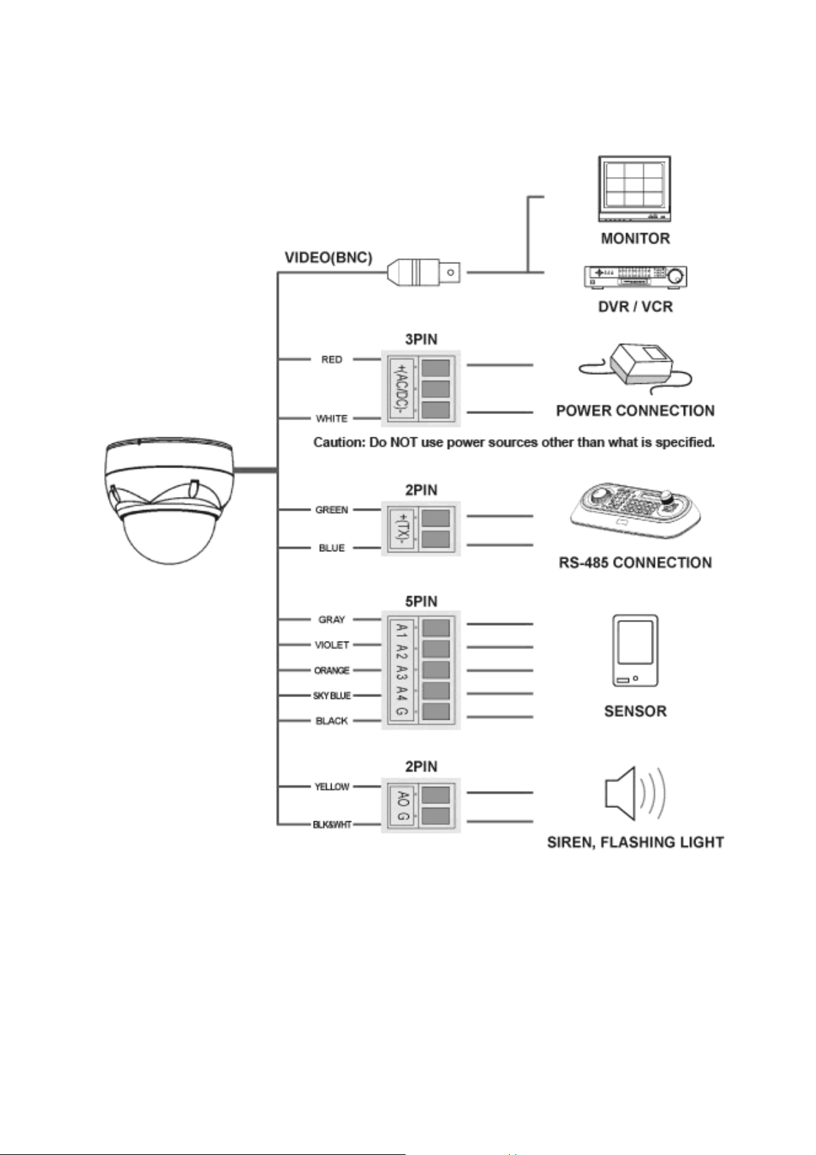
2.3 Basic Configuration of Dome Camera System
Figure 1 – Basic Installation Diagram
The dome camera must be installed by qualified service personnel in accordance with all local
and federal electrical and building codes.
6
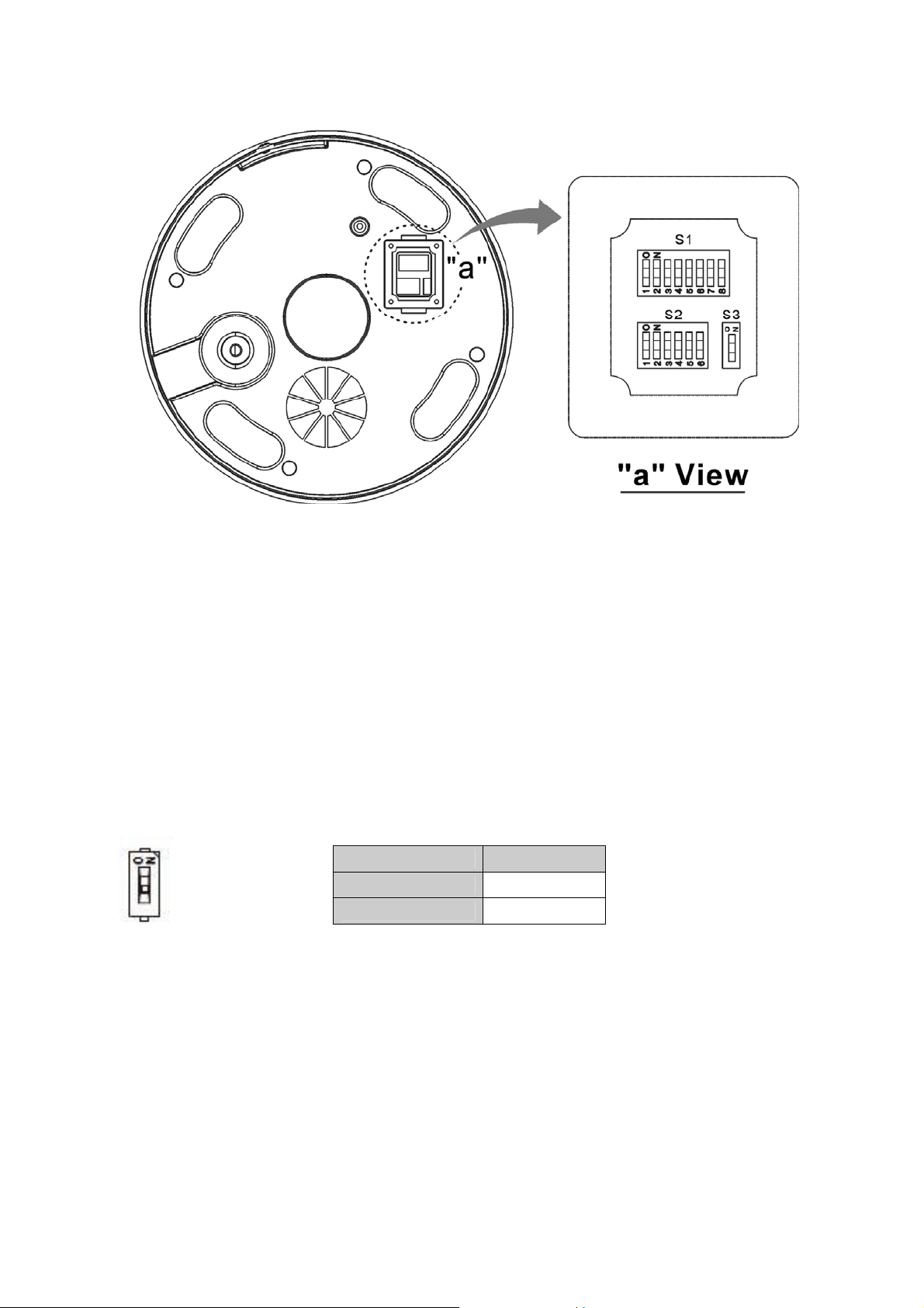
Figure 2 – Layout of DIP Switches
NOTE: Open the switch cover (position “a”) and change the setting of DIP switches.
The cover should be closed after setting DIP switches.
2.4 Setting Dome Camera Termination
The device which is connected at end of line, whether it is a dome camera or keyboard controller,
must have the cable for communication terminated by setting the appropriate DIP switch.
Without proper termination, there is potential for control signal errors. Total length of the cable for
communication should not exceed 4000ft (1.2km).
S3 D1
Terminated ON
S3
Not terminated
Figure 3 – Setting Dome Camera Termination
OFF
2.5 Setting Dome Camera Address (ID)
To prevent damage, each dome camera must have a unique address (ID).
When installing multiple dome cameras using a multiplexer, it is suggested that the dome camera
address match the multiplexer port number.
The factory default setting is 1.
Refer to Figure 4.1 ~ 4.6 for setting the dome camera address (ID).
7

Example: Port 1 = Dome 1, Port 2 = Dome 2 … Port 16 = Dome 16. If more than 16 dome
cameras are installed using two or more multiplexers, ID of the dome camera should be ID of
MUX x No. of camera IN. (e.g. multiplexer ID= n, Camera IN= m then ID of Dome =16x(n-1)+m )
S1
DOME ID
D1
(1)
1
2 OFF
3
4 OFF OFF
5
6 OFF
7
8 OFF OFF OFF
9
10 OFF
11
12 OFF OFF
13
14 OFF
15
16 OFF OFF OFF OFF
17
18 OFF
19
20 OFF OFF
21
22 OFF
23
24 OFF OFF OFF
25
26 OFF
27
28 OFF OFF
29
30 OFF
31
32 OFF OFF OFF OFF OFF
33
34 OFF
35
ON
ON ON
ON
ON ON ON
ON
ON ON
ON
ON ON ON ON
ON
ON ON
ON
ON ON ON
ON
ON ON
ON
ON ON ON ON ON
ON
ON ON
D2
(2)
OFF OFF OFF OFF OFF OFF OFF
ON
OFF
ON ON
OFF OFF
ON
OFF
ON ON ON
OFF OFF OFF
ON
OFF
ON ON
OFF OFF
ON
OFF
ON ON ON ON
OFF OFF OFF OFF
ON
Figure 4.1 – Setting Dome Camera Address (ID)
D3
(4)
OFF OFF OFF OFF OFF OFF
OFF OFF OFF OFF OFF OFF
ON
ON
OFF
OFF
ON ON
ON ON
OFF OFF
OFF OFF
ON
ON
OFF
OFF
ON ON ON
ON ON ON
OFF OFF OFF
OFF OFF OFF
D4
(8)
OFF OFF OFF OFF OFF
OFF OFF OFF OFF OFF
OFF OFF OFF OFF OFF
OFF OFF OFF OFF OFF
ON
ON
ON
ON
OFF
OFF
OFF
OFF
ON ON
ON ON
ON ON
ON ON
D5
(16)
OFF OFF OFF OFF
OFF OFF OFF OFF
OFF OFF OFF OFF
OFF OFF OFF OFF
OFF OFF OFF OFF
OFF OFF OFF OFF
OFF OFF OFF OFF
OFF OFF OFF OFF
ON
ON
ON
ON
ON
ON
ON
ON
D6
(32)
OFF OFF OFF
OFF OFF OFF
OFF OFF OFF
OFF OFF OFF
OFF OFF OFF
OFF OFF OFF
OFF OFF OFF
OFF OFF OFF
OFF OFF OFF
OFF OFF OFF
OFF OFF OFF
OFF OFF OFF
OFF OFF OFF
OFF OFF OFF
OFF OFF OFF
OFF OFF OFF
ON
ON
ON
ON
D7
(64)
OFF OFF
OFF OFF
OFF OFF
OFF OFF
D8
(128)
8

DOME ID
D1
(1)
36 OFF OFF
37
38 OFF
39
40 OFF OFF OFF
41
42 OFF
43
44 OFF OFF
45
46 OFF
47
48 OFF OFF OFF OFF
49
50 OFF
51
52 OFF OFF
53
54 OFF
55
56 OFF OFF OFF
57
58 OFF
59
60 OFF OFF
61
62 OFF
63
64 OFF OFF OFF OFF OFF OFF
65
66 OFF
67
68 OFF OFF
69
70 OFF
71
72 OFF OFF OFF
73
74 OFF
75
76 OFF OFF
77
78 OFF
79
80 OFF OFF OFF OFF
ON
ON ON ON
ON
ON ON
ON
ON ON ON ON
ON
ON ON
ON
ON ON ON
ON
ON ON
ON
ON ON ON ON ON ON
ON
ON ON
ON
ON ON ON
ON
ON ON
ON
ON ON ON ON
D2
(2)
OFF
ON ON
OFF OFF
ON
OFF
ON ON ON
OFF OFF OFF
ON
OFF
ON ON
OFF OFF
ON
OFF
ON ON ON ON ON
OFF OFF OFF OFF OFF
ON
OFF
ON ON
OFF OFF
ON
OFF
ON ON ON
Figure 4.2 – Setting Dome Camera Address (ID)
D3
(4)
ON
ON
OFF
OFF
ON ON
ON ON
OFF OFF
OFF OFF
ON
ON
OFF
OFF
ON ON ON ON
ON ON ON ON
OFF OFF OFF OFF
OFF OFF OFF OFF
ON
ON
OFF
OFF
ON ON
ON ON
D4
(8)
OFF OFF
OFF OFF
OFF OFF
OFF OFF
ON
ON
ON
ON
OFF
OFF
OFF
OFF
ON ON ON
ON ON ON
ON ON ON
ON ON ON
OFF OFF OFF
OFF OFF OFF
OFF OFF OFF
OFF OFF OFF
ON
ON
ON
ON
D5
(16)
OFF
OFF
OFF
OFF
OFF
OFF
OFF
OFF
ON ON
ON ON
ON ON
ON ON
ON ON
ON ON
ON ON
ON ON
OFF OFF
OFF OFF
OFF OFF
OFF OFF
OFF OFF
OFF OFF
OFF OFF
OFF OFF
ON
D6
(32)
ON
ON
ON
ON
ON
ON
ON
ON
ON
ON
ON
ON
OFF
D7
(64)
OFF OFF
OFF OFF
OFF OFF
OFF OFF
OFF OFF
OFF OFF
OFF OFF
OFF OFF
OFF OFF
OFF OFF
OFF OFF
OFF OFF
OFF OFF
OFF OFF
OFF OFF
OFF OFF
OFF OFF
OFF OFF
OFF OFF
OFF OFF
OFF OFF
OFF OFF
OFF OFF
OFF OFF
OFF OFF
OFF OFF
OFF OFF
OFF OFF
ON
ON
ON
ON
ON
ON
ON
ON
ON
ON
ON
ON
ON
ON
ON
ON
ON
D8
(128)
OFF
OFF
OFF
OFF
OFF
OFF
OFF
OFF
OFF
OFF
OFF
OFF
OFF
OFF
OFF
OFF
OFF
9

DOME ID
81
82 OFF
83
84 OFF OFF
85
86 OFF
87
88 OFF OFF OFF
89
90 OFF
91
92 OFF OFF
93
94 OFF
95
96 OFF OFF OFF OFF OFF
97
98 OFF
99
100 OFF OFF
101
102 OFF
103
104 OFF OFF OFF
105
106 OFF
107
108 OFF OFF
109
110 OFF
111
112 OFF OFF OFF OFF
113
114 OFF
115
116 OFF OFF
117
118 OFF
119
120 OFF OFF OFF
121
122 OFF
123
124 OFF OFF
125
D1
(1)
ON
ON ON
ON
ON ON ON
ON
ON ON
ON
ON ON ON ON ON
ON
ON ON
ON
ON ON ON
ON
ON ON
ON
ON ON ON ON
ON
ON ON
ON
ON ON ON
ON
ON ON
ON
D2
(2)
OFF OFF OFF
ON
OFF
ON ON
OFF OFF
ON
OFF
ON ON ON ON
OFF OFF OFF OFF
ON
OFF
ON ON
OFF OFF
ON
OFF
ON ON ON
OFF OFF OFF
ON
OFF
ON ON
OFF OFF
ON
OFF
Figure 4.3 – Setting Dome Camera Address (ID)
D3
(4)
OFF OFF
OFF OFF
ON
ON
OFF
OFF
ON ON ON
ON ON ON
OFF OFF OFF
OFF OFF OFF
ON
ON
OFF
OFF
ON ON
ON ON
OFF OFF
OFF OFF
ON
ON
OFF
OFF
ON ON ON ON ON
ON ON ON ON ON
D4
(8)
OFF
OFF
OFF
OFF
ON ON
ON ON
ON ON
ON ON
OFF OFF
OFF OFF
OFF OFF
OFF OFF
ON
ON
ON
ON
OFF
OFF
OFF
OFF
ON ON ON ON
ON ON ON ON
ON ON ON ON
ON ON ON ON
D5
(16)
ON
ON
ON
ON
ON
ON
ON
OFF
OFF
OFF
OFF
OFF
OFF
OFF
OFF
ON ON ON
ON ON ON
ON ON ON
ON ON ON
ON ON ON
ON ON ON
ON ON ON
ON ON ON
D6
(32)
OFF
OFF
OFF
OFF
OFF
OFF
OFF
OFF
OFF
OFF
OFF
OFF
OFF
OFF
OFF
ON ON
ON ON
ON ON
ON ON
ON ON
ON ON
ON ON
ON ON
ON ON
ON ON
ON ON
ON ON
ON ON
ON ON
ON ON
ON ON
D7
(64)
ON
ON
ON
ON
ON
ON
ON
ON
ON
ON
ON
ON
ON
ON
ON
D8
(128)
OFF
OFF
OFF
OFF
OFF
OFF
OFF
OFF
OFF
OFF
OFF
OFF
OFF
OFF
OFF
OFF
OFF
OFF
OFF
OFF
OFF
OFF
OFF
OFF
OFF
OFF
OFF
OFF
OFF
OFF
OFF
OFF
OFF
OFF
OFF
OFF
OFF
OFF
OFF
OFF
OFF
OFF
OFF
OFF
OFF
10
 Loading...