

Eneo EDCH/143E/C Instruction Manual
1
ALL-IN-ONE DOME CAMERA
EDCH/143E/C
Instruction Manual

2
Safety Instructions
• Read these safety instructions and the operation manual first before you install and commission
the camera.
• Keep the manual in a safe place for later reference.
• Protect your camera from contamination with water and humidity to prevent it from permanent
damage.
Never switch the camera on when it gets wet. Have it checked at an authorized service center in
this case.
• Never operate the camera outside of the specifications as this may prevent the camera
functioning.
• Do not operate the cameras beyond their specified temperature, humidity or power ratings.
• Operate the camera only at a temperature range of -10°C to +50°C and at a humidity of
max. 90%.
• To disconnect the power cord of the unit, pull it out by the plug. Never pull the cord itself.
• Pay attention when laying the connection cable and observe that the cable is not subject to
heavy loads, kinks, or damage and no moisture can get in.
• Do not attempt to disassemble the camera board from the dome.
• The warranty becomes void if repairs are undertaken by unauthorized persons.
Do not open the camera housing.
• Never point the camera towards the sun with the aperture open. This can destroy the sensor.
• Installation, maintenance and repair have to be carried out only by authorized service centers.
Before opening the cover disconnect the unit from mains input.
• Contact your local dealer in case of malfunction.
• Only use original parts and original accessories from Videor E. Hartig GmbH.
• Do not use strong or abrasive detergents when cleaning the dome.
Use a dry cloth to clean the dome surface.
In case the dirt is hard to remove, use a mild detergent and wipe gently.
• All openings provided in the housing for assembly purposes must be closed and/or sealed.
• The installer is responsible for ensuring that the degree of protection as per the technical
specifications is upheld, e.g. by using all enclosed gasket seals and O-rings, by
waterproofing the cable exits with silicon or through laying the cable in such a way that
the cable does not act as a „gutter”.
• During assembly, care must be taken to ensure that existing seals are correctly inserted
and are not displaced as a result of assembly.
You must not continue to use damaged seals.
NOTE: This is a class A digital device. This digital device can cause harmful interference in
a residential area; in this case the user may be required to take appropriate
corrective action at his/her own expense.

3
Table of Contents
Chapter 1 — Introduction........................................................................................................... 4
1.1 Features..............................................................................................................................................4
Chapter 2 — Installation and Configuration..........................................................................5
2.1 Package Contents............................................................................................................................5
2.2 Installation..........................................................................................................................................5
2.3 Basic Configuration of Dome Camera System.........................................................................6
2.4 Setting Dome Camera Termination and Full State Bias.........................................................7
2.5 Setting Dome Camera Address (ID).............................................................................................8
2.6 Setting Dome Camera Protocol and Video................................................................................8
2.7 Connections.......................................................................................................................................9
2.8 Getting Started..............................................................................................................................10
Chapter 3 — Program and Operation..................................................................................11
3.1 Dome Camera Selection.............................................................................................................11
3.2 Accessing the On-Screen Menu Utility...................................................................................11
3.3 How to control the On-Screen Menu Utility...........................................................................12
3.4 Auto Scan (Shortcut: SCAN ) ....................................................................................................12
3.5 Preset (Shortcut: PRST) ............................................................................................................14
3.6 Shortcut of Preset Program....................................................................................................... 16
3.7 Tour (Shortcut: TOUR)................................................................................................................17
3.8 Pattern (Shortcut: PTRN) ...........................................................................................................18
3.9 Alarm................................................................................................................................................19
3.10 Area Title.......................................................................................................................................20
3.11 Privacy Zone................................................................................................................................ 21
3.12 Camera Menu Type1 (22X model)..........................................................................................22
3.14 Dome Setup .................................................................................................................................25
3.14 Function Run...............................................................................................................................31
Appendix A — Specifications................................................................................................ 33
Appendix B — Troubleshooting........................................................................................... 36
Appendix C — Glossary.......................................................................................................... 37
Appendix D — Short Cut Key................................................................................................ 39
Appendix E — Wall Mount (not supplied).......................................................................... 41
Appendix F — Ceiling Mount (not supplied)..................................................................... 42
4
Chapter 1 — Introduction
1.1 Features
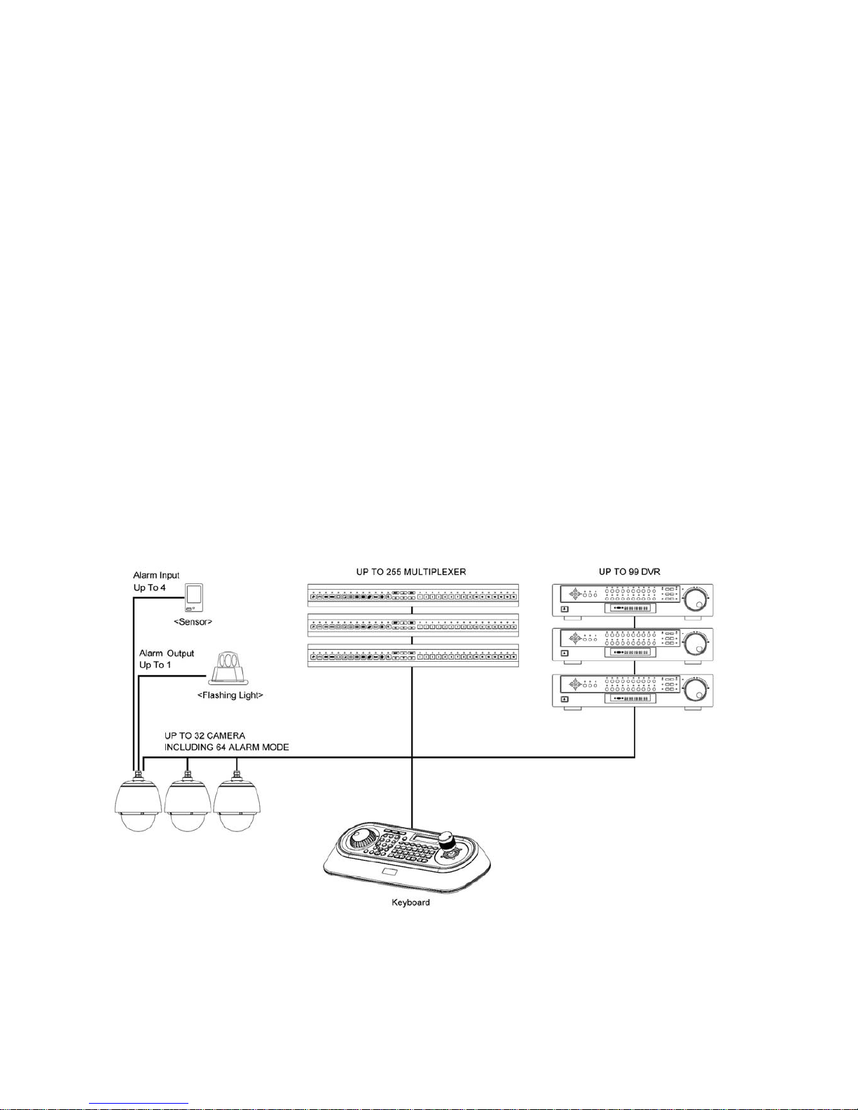
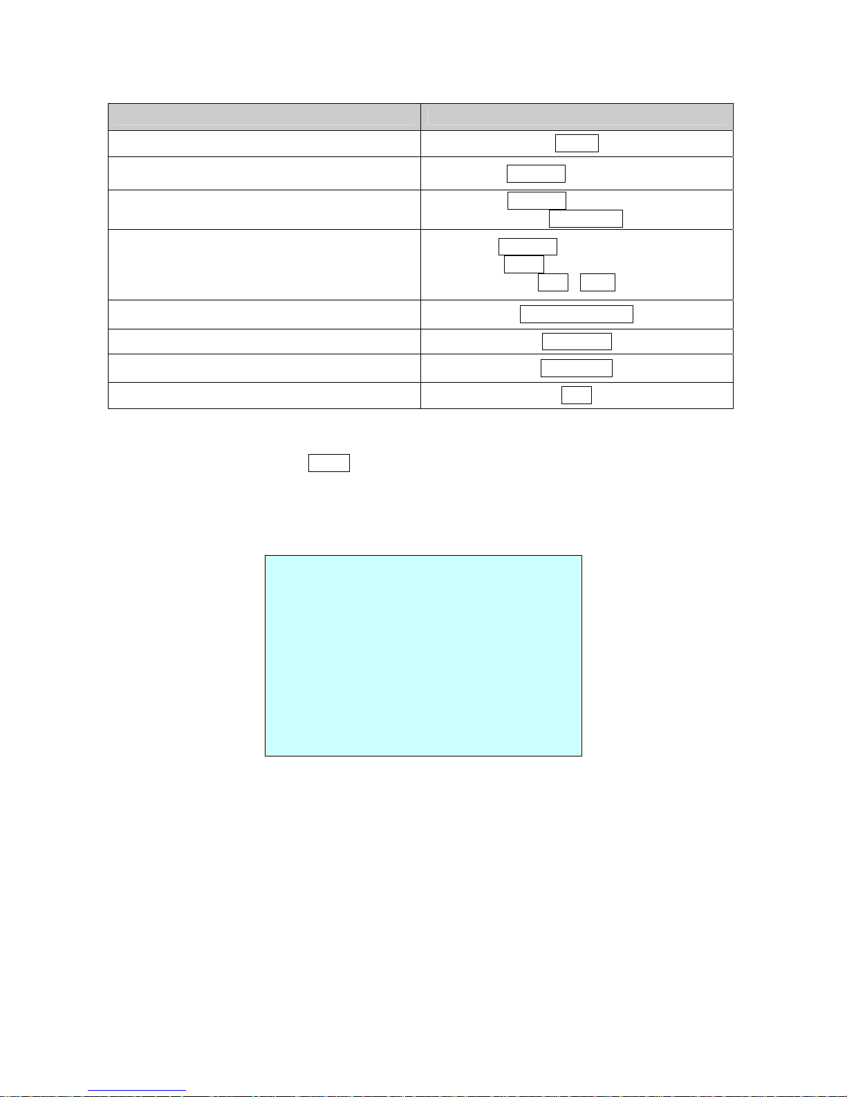
The dome camera and the Keyboard Controller make up the building blocks for any
surveillance/security system. Using multiple Keyboard Controllers and multiple dome cameras, no
place is too large for monitoring. Extensible and flexible architecture facilitates remote control
functions for a variety of external switching devices such as multiplexers and DVRs.
• Vandalism resistant colour/b&w dome camera
• 22x optical and 16x digital zoom (242 total)
• Zoom lens F1.6/3.9-85.8mm/ Removable IR cut filter
• High and low speed shutter control (MES/ESC/DSS)
• 160 presets / 4 patterns / Digital flip
• 4 tours and 4 autoscans
• 8 dynamic window blanking (privacy zones)
• RS-485 control interface
• Supply voltage: 18 to 30VAC, 50/60Hz
• Outdoor housing with clear bubble
• Sunshield, heater and blower kit included
• Ready for installation (prewired)
Figure 1 – Typical System Configuration

5
Chapter 2 — Installation and Configuration
2.1 Package Contents
AIO(All In One) is design to a compact, small size, hard Dome Camera Housing.
The housing is constructed of aluminum, steel and plastic. The housing is designed to be mounted
both wall and ceiling type.
The housing meets the Protection Classification IP66 standards for dust and moisture resistance.
This housing has one fan and one heater controlled thermostatically.
The thermostat of heater is set to turn it on 5˚(±5) and to turn it off 15˚(±5).
The Sunshield is available for application to avoid the direct rays of the sun.
Dome Camera housing ………………………1
Instruction Manual (This Document) ………………………1
Torx Wrench ………………………1
2.2 Installation
You need one optional mount kit of the wall mount and the ceiling mount to install.
The wall or ceiling mount must be attached to a structural object such as hard wood, concrete that
will support the weight of the mount and AIO.
The use of a solid backboard is recommended when attaching to gypsum walls.
1. Remove the Protection pad and the tape from attached the dome camera.
2. Attach the mounting base to wall using the supplied M8 tapping screw and plastic bushing.
(Ceiling using the supplied M6 tapping screw and bushing)
3. Wind the both thread of the pipe end with Teflon tape about 20times for sealing.
Then use a silicone rubber sealant to seal the area where the wall (ceiling) mount
and the pipe meet.
4. Place a bead of silicone sealant around the wall and ceiling mount mounting flange, press
it to the surface and line up the flange hole with drilled holes.
5. Refer to the appendix E and F.
CAUTION : A silicone rubber sealant must be applied to seal the housing to secure
waterproofing
6
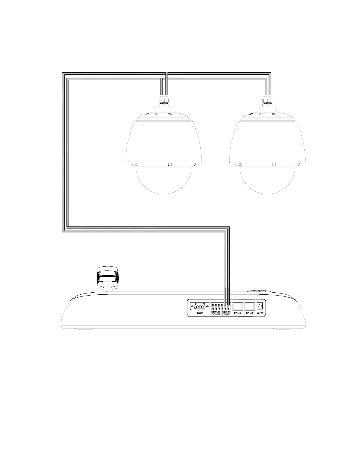
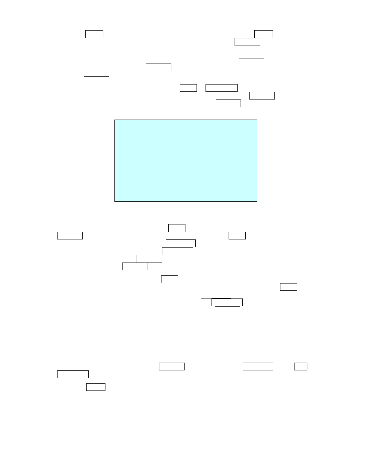
2.3 Basic Configuration of Dome Camera System
22 AWG UTP CABLE
KEYBOARD
Figure 2 – Basic Installation Diagram
The dome camera must be installed by qualified service personnel in accordance with all local and
federal electrical and building codes.
7
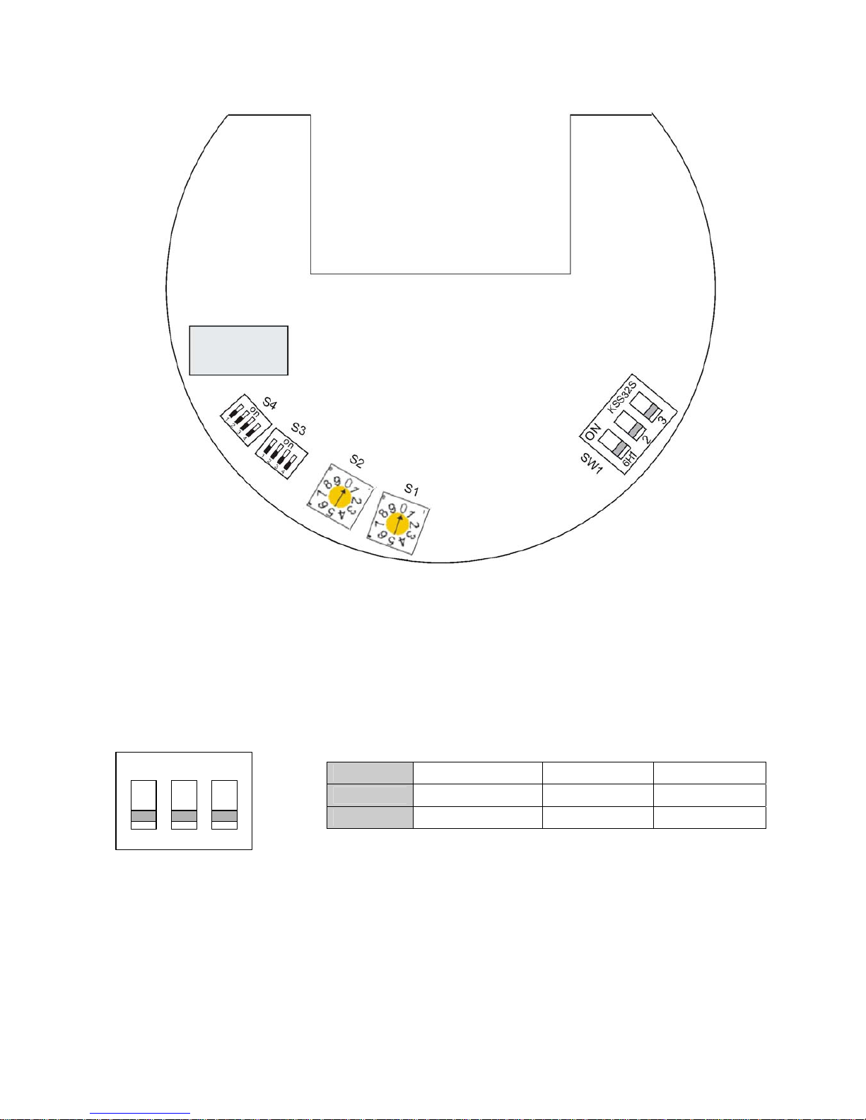
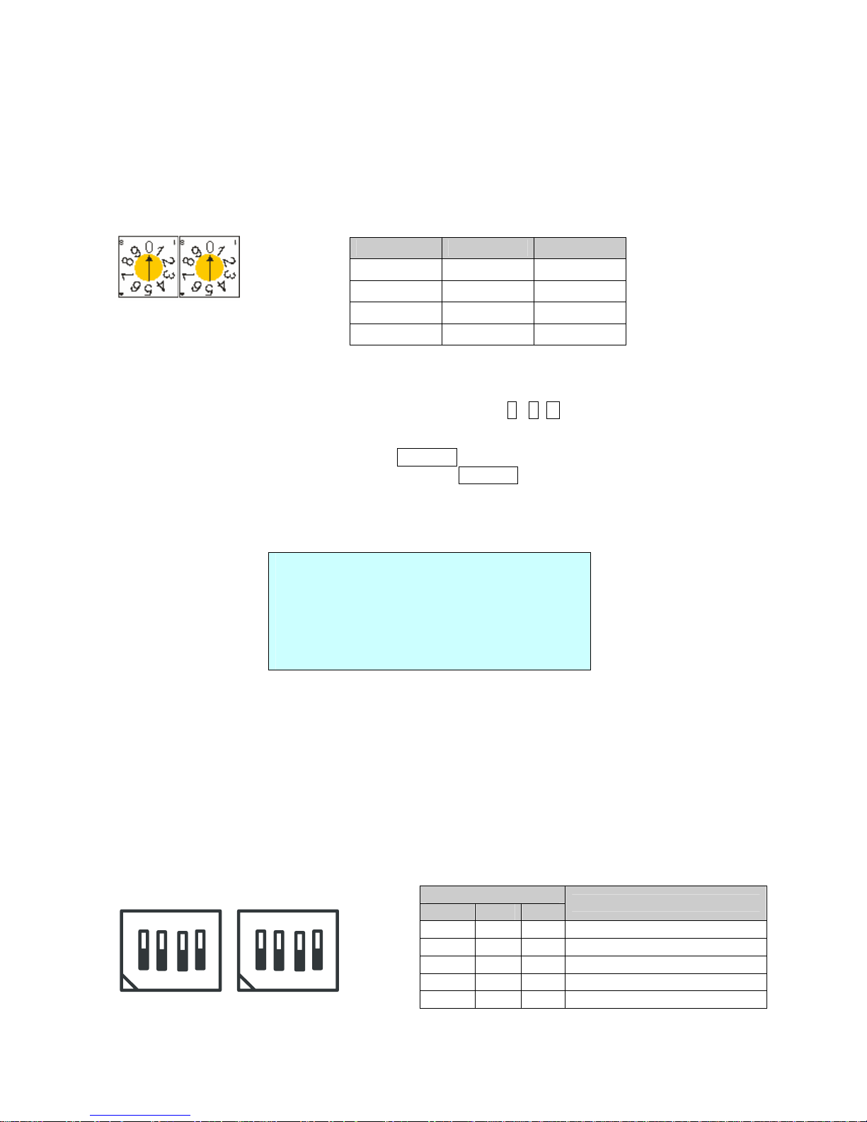
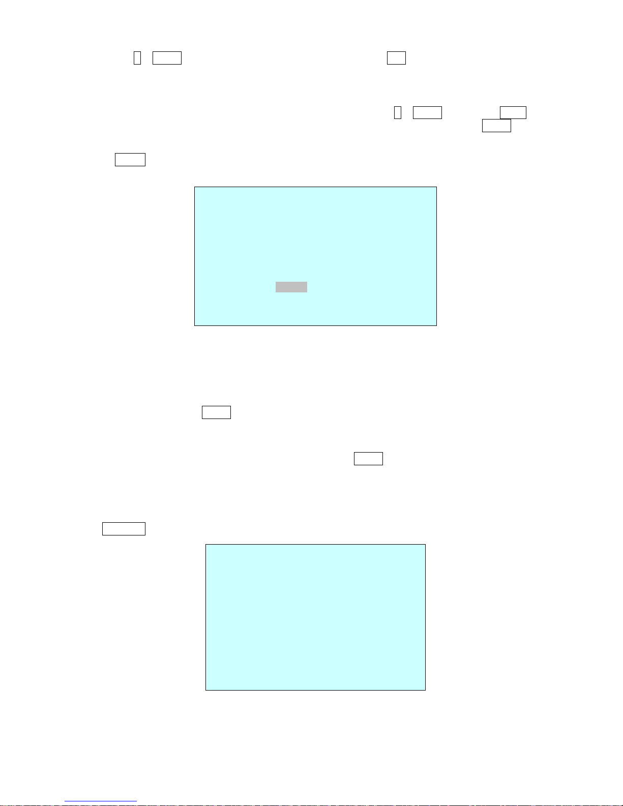
Figure 3 – Layout of Switches
2.4 Setting Dome Camera Termination and Full State Bias
The device which is connected at end of line, whether it is a dome camera or keyboard controller,
must have the cable for communication terminated by setting the appropriate DIP switch. Without
proper termination, there is potential for control signal errors. Total length of the cable for
communication should not exceed 1.2km.
SW1
Figure 4 – Setting Dome Camera Termination
When you don’t use our keyboard, the other keyboard may not control our dome. At that time you
set the DIP switch 2 and 3 of the SW1 to ON to add the external fail safe network of the RS-485
line at the nearest dome only from the keyboard.
SW1
1 2 3
ON
Terminated FULL UP FULL DOWN
OFF
Not terminated OFF OFF
ON KSS32S
6H
12 3
8
2.5 Setting Dome Camera Address (ID)
To prevent damage, each dome camera must have a unique address (ID). When installing
multiple dome cameras using a multiplexer, it is suggested that the dome camera address match
the multiplexer port number.
Example: Port 1 = Dome 1, Port 2 = Dome 2 … Port 16 = Dome 16. If more than 16 dome
cameras are installed using two or more multiplexers, ID of the dome camera should be ID of MUX
x No. of camera IN. (e.g. multiplexer ID= n, Camera IN= m then ID of Dome =16x(n-1)+m )
S2 S1
Figure 5 – Setting Dome Camera Address (ID)
When you set the dome camera address (ID) over99, press 2 , 5 , 0 , and PRST keys of the
keyboard. Then the FACTORY SETUP displays as below.
1. Select the DOME ID option by using the Joystick .
2. Change the number of the DOME ID by using the Joystick to the right.
Eg.) DOME ID:01XX, (XX means the number of the DIP switch): DOME ID=100+XX
When the DIP switch is 99, DOME ID=199
3. Select Save and Exit by pushing the Joystick to the right. Press ESC to exit the Preset menu
without saving.
FACTORY SETUP
DOME ID : 00XX
TOUR DWELL TIME : 03SEC
ANSWER DELAY : 03SEC
SAVE AND EXIT (ESC TO CANCEL)
TOUR DWELL TIME means the dwell time between tours.
ANSWER DELAY means the response time of the dome and you don’t need to change in normal
condition.
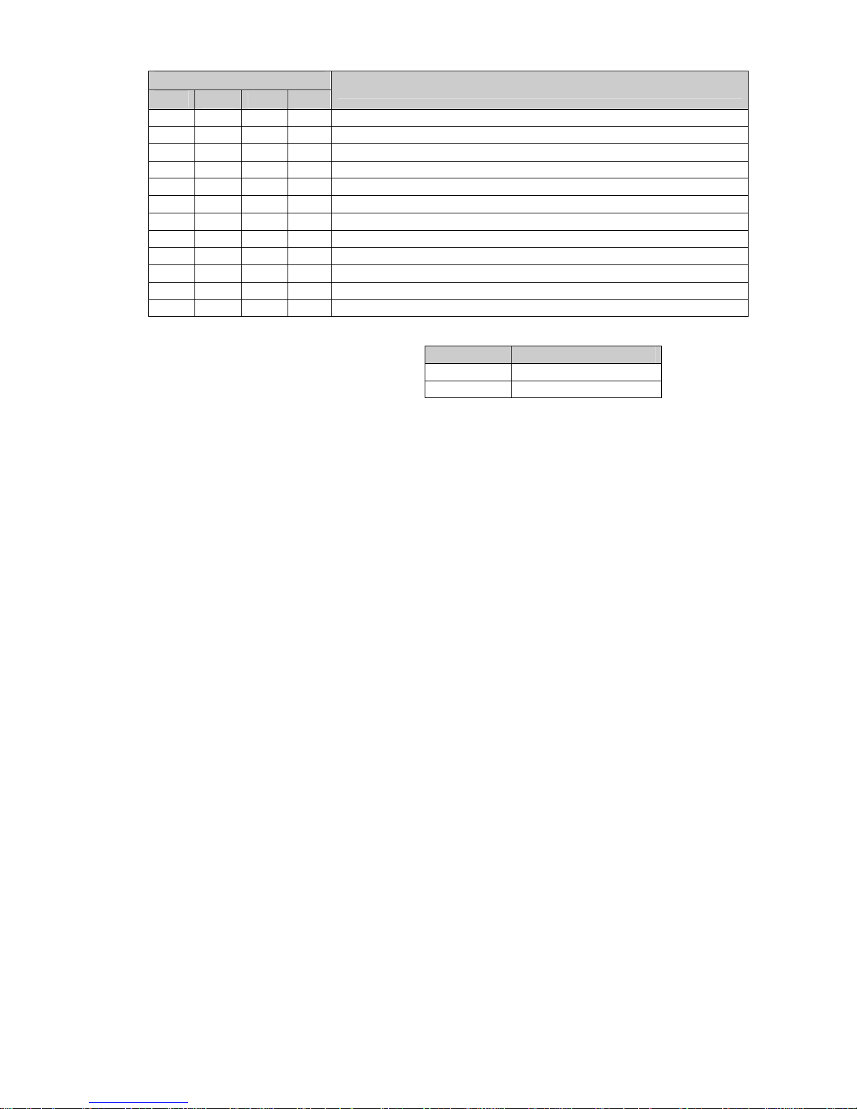
2.6 Setting Dome Camera Protocol and Video
If a dome camera is to be installed with a Fastrax keyboard controller, select F2E protocol.
Consult service personnel if a dome camera is installed with device other than a keyboard
controller.
DOME ID
S2 S1
1
0 1
2
0 2
.
. .
99
9 9
S3
D1 D2 D3
BAUD RATE
Off Off Off 2400 bps
Off Off On 4800 bps
Off On Off 9600 bps (Default)
Off On On 19200 bps
On Off Off 38400 bps
S4
S3
o
n
1
2
3
4
o
n
1
2
3
4
9
S4
D1
D2 D3 D4
PROTOCOL
Off Off Off Off F2,F2E,Pelco-D,Pelco-P:default
Off Off On Off F2,F2E
Off On Off Off Sensormatic
Off On On Off Pelco-D, Pelco-P
On Off Off Off Vicon
On Off On Off Ernitec
On On Off Off Reserved
On On On Off F2
Off Off Off On Philips(Bosch)
Off Off On On Reserved
Off On Off On Dynacolor
Off On On On Reserved
You can set video type with dip switch.
Select video type with D4 in S3.
2.7 Connections
Connector 1 :AC+ / AC- /G /R- /R+/G
• Connecting the Power( AC+ / AC-)
Connect the power of AC 24V 1A for the dome camera.
Use certified / Listed Class 2 power supply transformer only.
• Connecting to the RS485
The dome camera can be controlled remotely by an external device or control system, such as a
control keyboard, using RS485 half-duplex serial communications signals. Connect Marked R+, Rto Tx+ and Tx- of the RS485 control system.
Connector 2 :F+ / F-
• Connecting the Power( F+ / F-) for the heater and the fan
Connect the power of AC 24V 2.2A for the heater and the fan
Use certified / Listed Class 2 power supply transformer only.
Connector 3 :AL1/AL2/AL3/AL4/G
Alarm In
You can use external devices to signal the dome camera to react on events. Mechanical or
electrical switches can be wired to the AL (Alarm In) and G (Ground) connectors.
See Chapter 3 — Program and Operation for configuring alarm input.
S3-D4 VIDEO TYPE
Off NTSC
On PAL
10
Connector 4 :COM/NC/NO
Alarm Output
The dome camera can activate external devices such as buzzers or lights. Connect the device to
the NC (NO) (Alarm Out) and COM (Common) connectors. See Chapter 3 — Program and
Operation for configuring alarm output.
Connector 5 :BNC
• Connecting Video out connector
Connect the video out (BNC) connector to the monitor or video input.
CONNECTOR 1 : AC+ / AC- /G /R- /R+/G CONNECTOR 2 : F+ / F-
CONNECTOR 3 : AL1/AL2/AL3/AL4/G CONNECTOR 4 : COM/NC/NO
2.8 Getting Started
Once installed apply power to the dome camera. The dome camera will start a configuration
sequence.
COLOR DESCRIPTION
RED
AC+:AC 24V
ORANGE
AC-:AC 24V
YELLOW G:GND
GREEN R GRAY R+
BLUE G:GND
COLOR DESCRIPTION
BLACK F+: AC 24V (HEAT ER & FAN)
BROWN F-:AC 24V (HEATER & FAN)
COLOR DESCRIPTION
GRAY AL1:ALARM INPUT 1
BLUE AL2:ALARM INPUT 2
GREEN AL3: ALARM INPUT 3
YELLOW AL4:ALARM INPUT 4
ORANGE G:GND
COLOR DESCRIPTION
RED COM:COMMON
BROWN NC:ALARM OUTPUT
BLACK NO:ALARM OUTPUT
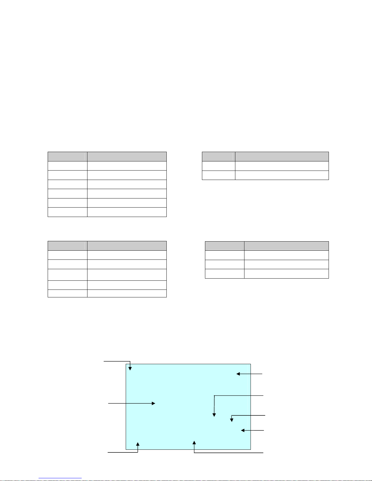
001 AF AE
EMPTY DATA
DOMEID:0001
ALARM:1 W→360.0,090.0
INFORMATION
DISPLAY
FUNCTION
UNDER RUNNING
ALARM DISPLAY
CAMERA TITLE
CAMERA ID
VIEW DIRECTION
PAN & TILT ANGLE
PRESET TITLE
AREA TITLE
STATUS of
FOCUS and AE
11
OSD Position
The dome can move the OSD position in the OSD position setup.
OSD Position Setup
Chapter 3 — Program and Operation
3.1 Dome Camera Selection
Before you program or operate a dome camera, you must select the dome camera by pressing the
dome camera No. + CAM
Example: Pressing 1 , 0 and CAM key sequentially will select dome camera 10. The selected
dome camera ID will be displayed on the LCD monitor of the keyboard controller.
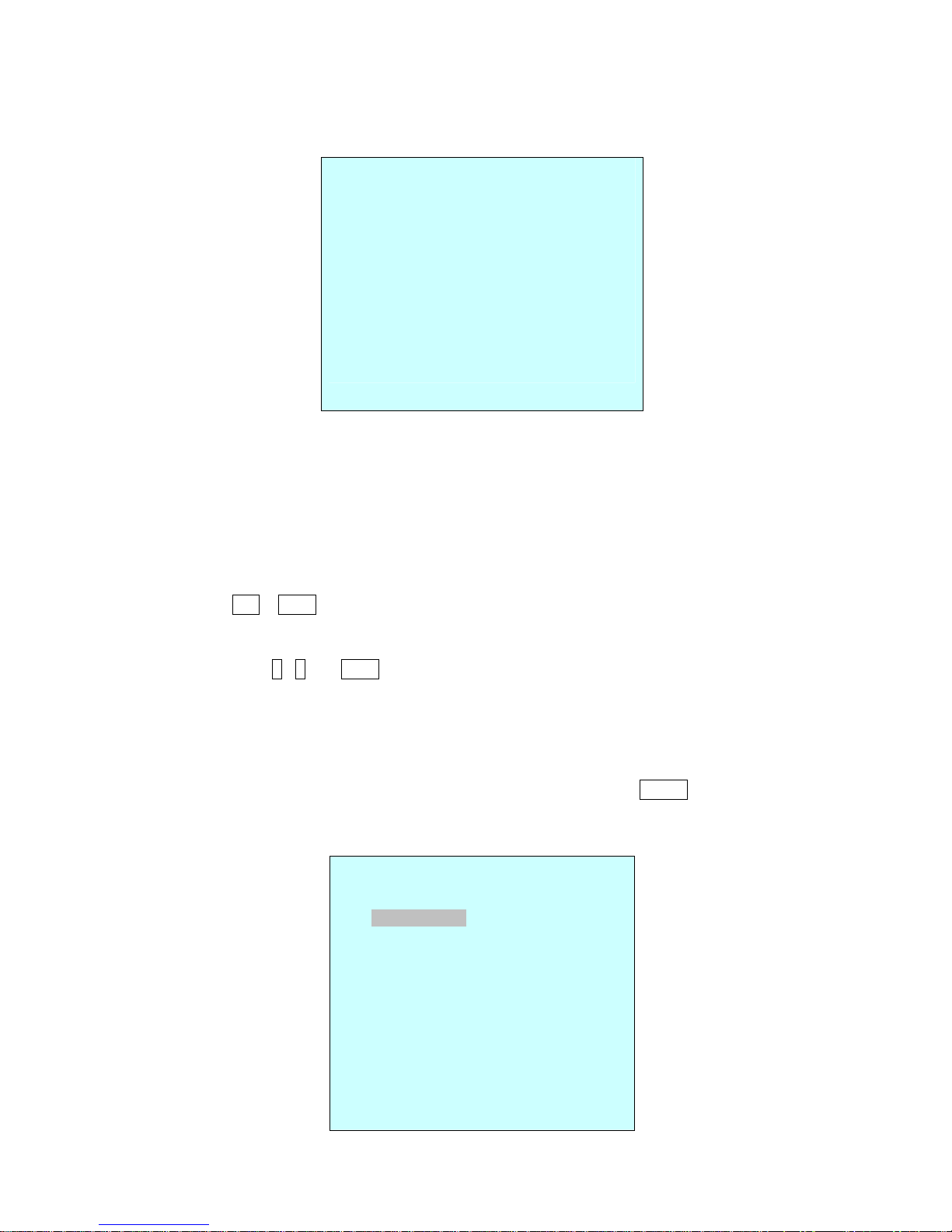
3.2 Accessing the On-Screen Menu Utility
You can call up the On-screen menu utility on your monitor by pressing MENU key on the
keyboard controller, the following On-screen menu utility will appear:
(AREA TITLE) (AF AE)
(FUNC TITLE )
(CTRL KEY TO MOVE)
SAVE AND EXIT(ESC TO CANCEL)
(ALARM MESSAGE) (DOME ID…)
(ANGLE…)
DOME MENU
AUTO SCAN
PRESET
TOUR
PATTERN
ALARM
AREA TITLE
PRIVACY ZONE
CAMERA
DOME SETUP
FUNCTION RUN
EXIT(ESC TO EXIT)
12
3.3 How to control the On-Screen Menu Utility
Function Button
Call the On-screen menu utility
MENU
Navigate through the menu items.
Joystick up or down
Go into the sub-menu items.
Joystick left or right
or IRIS Open
Change value.
Enter the editing title mode.
Joystick left or right or
Zoom handle twist or
Tele , Wide
Change value of angle
CTRL + Joystick
Enter the changing angle mode.
IRIS Open
Exit the changing angle mode.
IRIS Close
Escape (EXIT)
ESC
3.4 Auto Scan
(Shortcut: SCAN)
The Auto scan supports up to 5 programmed angles at user-programmable speeds. Follow these
steps to program Auto Scan:
NUMBER :01 -04, 09:AUTO PAN mode
TITLE :up to 12 characters.
MODE :NORMAL, VECTOR, RANDOM (AUTO PAN mode :NORMAL, RANDOM only)
NORMAL: Move from start point to end point in panning only.
VECTOR: Move from start point to end point including tilt and zoom simultaneously and
linearly. In some model, the zoom is fixed at wider angle and the zoom
magnification information is not displayed.
RANDOM: Move randomly between the start point and the end point.
SPEED : 1 - 13 step, the lower number means the slower speed.
SCAN DIR : Set the scan direction, CCW(Counter Clock Wise), CW(Clock Wise)
SWAP : Swap the start point for the end point.
DWELL : Set the dwell time at the both end, 01 – 99 seconds
AUTO SCAN SETUP
NUMBER : 01
TITLE : A01
MODE : NORMAL
SPEED : 5 STEP
START ANGLE : ----- ----- --END ANGLE : ----- ----- --SCAN DIR : CCW
SWAP : OFF
DWELL : 03 SEC
SAVE AND EXIT(ESC TO CANCEL)
13
1. Press the SCAN key to enter the auto scan menu directly. Or press the MENU key to display
the main menu on the monitor. Scroll to Auto Scan and push the Joystick to the right.
2. Select the” NUMBER” and set the desired number by pushing the Joystick left or right.
3. Select the “TITLE” and twist the Joystick to enter the title edit mode.
4. Twist the Joystick by changing the alphanumeric characters and move the next position. Or
move down to the character table and press CTRL or IRIS OPEN at the desired character then
the cursor position moves to the next position automatically. Push the Joystick left or right at
the “ALL DELETE” field to delete all characters. Push the Joystick left or right at the “EXIT”
field to finish title edit menu.
5. Select “MODE” and “SPEED”.
6. Select “START ANGLE”. Hold down the CTRL key while selecting the start position using the
Joystick. Current panning position will be displayed. Release CTRL key to complete the
selection of the start position. Or Press IRIS Open then the “CTRL” displays. Move the desired
position and the zoom position. Press IRIS Close then the “CTRL” disappears. To adjust at the
0.1 degree interval, twist the Joystick at the pan field and the tilt field. To adjust at the one
zoom interval, twist the Joystick at the zoom field.
7. Select “END ANGLE.” Hold down the CTRL key while moving the Joystick to select the end
position. The end position angle should be larger than start position. Release the CTRL key to
complete the selection of the end position. Or Press IRIS Open then the “CTRL” displays.
Move the desired position and the zoom position. Press IRIS Close then the “CTRL”
disappears. To adjust at the 0.1 degree interval, twist the Joystick at the pan field and the tilt
field.
8. Set “SCAN DIR” to CCW or CW.
9. Select “SWAP”. Set to ON, to exchange the start angle and the end angle.
10. Set “DWELL TIME”.
11. Select Save and Exit and push the Joystick to the right or press IRIS Open. Press ESC or
IRIS Close to exit the program without saving.
Pressing the HOME key delete stored data at the angle field.
To set the position using the preset position:
a. Before entering the Auto Scan menu, select a preset position as a starting point for Auto Scan.
TITLE EDIT MENU
A01
*
A B C D E F G H I J
K L M N O P Q R S T
U V W X Y Z 0 1 2 3
4 5 6 7 8 9 ( )
ALL DELETE
EXIT (ESC TO EXIT)
14
Example: 2 + PRST and do step 1 to 4. In step 5, just press the Ctrl key at the start angle position,
the current position will be displayed as a start position.
b. Save and exit from the menu.
c. In normal mode, call a preset to be the end point of scan. Press 3 + PRST then press Scan key
to enter the Auto Scan menu. Move the cursor position to END ANGLE. Just press CTRL key at
the end angle position. Save and exit from the menu.
Press SCAN key on the angle field to display with the small OSD. Then the screen will show as
below.
The setting procedure is the same as above.
NOTE: 09:AUTO-PAN mode(Endless panning)
3.5 Preset
(Shortcut: PRST)
If you need to view specific places routinely, you should program presets. A preset is a
programmed video scene with automatic pan, tilt, zoom, focus, and AE settings. Once
programmed, placing the number position and pressing a PRST button on your controller calls up
that preset automatically. In addition, presets may be assigned to alarm actions or as the “home”
position for the dome camera. As many as 160 presets, whose positions are saved in the dome’s
firmware, may be programmed.
There are two pages of preset menu. Each page has 80 presets. Pages can be scrolled by pushing
the Joystick to the Left or Right on the first or last No. of Preset.
- : blank preset position
* : position has the preset
█ : Current cursor position
Follow steps below to store the Preset positions:
AUTO SCAN AREA SETUP
(CTRL KEY)
NUMBER01
START: ----- ----- --END : ----- ----- --EXIT(ESC TO EXIT)
PRESET SETUP
NUMBER : 001
TITLE : --CAMERA SET
DWELL : --- SEC
12345678901234567890
00 █**----------------02 -------------------04 --------------------
06 -------------------NEXT PAGE
EXIT(ESC TO CANCEL)
 Loading...