

Page 1
"Smarter Timing Solutions"
Tempus LX
Network Time Server
GPS
User Manual
Page 2

Page 3

Tempus LX
GPS
Network Time Server User Manual
Preface
Thank you for purchasing the Tempus LX Network Time Server. Our goal in developing this product
is to bring precise, Universal Coordinated Time (UTC) into your network quickly, easily and reliably.
Your new Tempus LX is fabricated using the highest quality materials and manufacturing processes
available today, and will give you years of troublefree service.
About EndRun Technologies
EndRun Technologies is dedicated to the development and renement of the technologies required to
fulll the demanding needs of the time and frequency community.
Our innovative engineering staff, with decades of experience in the research and development of
receiver technology for the Global Positioning System (GPS), has created our window-mount GPS
antenna and extended hold-over oscillator-control algorithms.
The instruments produced by EndRun Technologies have been selected as the timing reference for
such rigorous applications as computer synchronization, research institutions, aerospace, network
quality-of-service monitoring, satellite base stations, and calibration laboratories.
EndRun Technologies is committed to fullling your precision timing needs by providing the most
advanced, reliable and cost-effective time and frequency equipment available in the market today.
Trademark Acknowledgements
IBM-PC, Linux, NotePad, Timeserv, UNIX, Windows NT, WordStar are registered trademarks of the
respective holders.
Part No. USM3015-0000-000 Revision 11
May 2008
Copyright © EndRun Technologies 2005-2008
Te m p u s L X G P S U s e r M a n u a l
Page 4

Te m p u s L X G P S U s e r M a n u a l
About This Manual
This manual will guide you through simple installation and set up procedures.
Introduction – The Tempus LX, how it works, where to use it, its main features.
Basic Installation – How to connect, congure and test your Tempus LX with your network.
Client Set-Up – Two sections; one for Unix-like platforms and one for Windows NT/2000/XP.
Console Port – Description of the Linux console commands for use over the network and serial ports.
Front-Panel Keypad and Display – How to operate the user interface that provides convenient setup and
monitoring of the instrument.
If you detect any inaccuracies or omissions, please inform us. EndRun Technologies cannot be held
responsible for any technical or typographical errors and reserves the right to make changes to the
product and manuals without prior notice.
Warranty
This product, manufactured by EndRun Technologies, is warranted against defects in material and
workmanship for a period of three years from date of shipment, under normal use and service. During the warranty period, EndRun Technologies will repair or replace products which prove to be
defective.
For warranty service or repair, this product must be returned to EndRun Technologies. Buyer shall
prepay shipping charges to EndRun Technologies and EndRun Technologies shall pay shipping
charges to return the product to Buyer. However, Buyer shall pay all shipping charges, duties, and
taxes for products returned to EndRun Technologies from another country.
Products not manufactured by EndRun Technologies but included as an integral part of a system (e.g.
peripherals, options) are warranted for ninety days, or longer as provided by the original equipment
manufacturer, from date of shipment.
Extended Warranty
The MTBF (Mean Time Between Failures) for this product is 225,000 hours (25 years). After the
initial warranty period it is most cost-effective for the customer to repair the unit on an “as needed basis”, rather than pay for an extended warranty or the annually recurring fees of a service contract..
Limitation of Warranty
The foregoing express warranty shall not apply to defects resulting from improper or inadequate
maintenance by Buyer or User, Buyer-supplied software or interfacing, unauthorized modication or
misuse, operation outside of the environmental specications for the product, or improper site preparation or maintenance.
TO THE EXTENT PERMITTED BY LAW, THIS WARRANTY AND REMEMDIES SET FORTH
ABOVE ARE EXCLUSIVE AND IN LIEU OF ALL OTHER WARRANTIES, REMEDIES AND
CONDITIONS WHETHER ORAL OR WRITTEN, STATUTORY, EXPRESS, OR IMPLIED. AS
PERMITTED BY APPLICABLE LAW, ENDRUN SPECIFICALLY DISCLAIMS THE IMPLIED
WARRANTIES OF MERCHANTABILITY OR FITNESS FOR A PARTICULAR PURPOSE.
Te m p u s L X G P S U s e r M a n u a l
Page 5

Warranty Repair
If you believe your equipment is in need of repair, call EndRun Technologies and ask for a customer
service agent. It is important to contact us rst as many problems may be resolved with a phone call.
Please have the serial number of the unit and the nature of the problem available before you call. If
it is determined that your equipment will require service, we will issue an RMA number. You will be
asked for contact information, including your name, address, phone number and e-mail address.
Ship the unit prepaid in the original container or a container of sufcient strength and protection to
EndRun Technologies. EndRun will not be responsible for damage incurred during shipping to us.
Be sure the RMA number is clearly identied on the shipping container. Our policy is to x or repair
the unit within 5 business days. If it is necessary to order parts or if other circumstances arise that
require more than 5 days, an EndRun service technician will contact you.
Repair After Warranty Expiration
If the warranty period has expired, we offer repair services for equipment you have purchased from
EndRun. Call and ask for a customer service agent. It is important to contact us rst as many problems may be resolved with a phone call. Please have the serial number of the unit and the nature
of the problem available before you call. If it is determined that the equipment has failed and you
want EndRun to perform the repairs, we will issue you an RMA number. Ship the unit prepaid in
the original container or a container of sufcient strength and protection to EndRun Technologies.
EndRun will not be responsible for damage incurred during shipping to us. Customer is responsible
for shipping costs to and from EndRun Technologies. Be sure the RMA number is clearly identied
on the shipping container. After the equipment has been received we will evaluate the nature of the
problem and contact you with the cost to repair (parts and labor) and an estimate of the time necessary to complete the work.
Limitation of Liability
The remedies provided herein are Buyer’s sole and exclusive remedies. EndRun Technologies shall
not be liable for any direct, indirect, special, incidental or consequential damages, whether based on
contract, tort or any other legal theory.
EndRun Contact Information
Address: EndRun Technologies
2270 Northpoint Parkway
Santa Rosa, CA 95407
Phone: (707)573-8633
Fax: (707)573-8619
Sales: 1-877-749-3878 or (707)573-8633
[email protected]
Support: 1-877-749-3878 or (707)573-8633
[email protected]
Te m p u s L X G P S U s e r M a n u a l
Page 6

Te m p u s L X G P S U s e r M a n u a l
Te m p u s L X G P S U s e r M a n u a l
Page 7

Table of Contents
Preface . . . . . . . . . . . . . . . . . . . . . . . . . . . . . . . . . . . . . . . . . . . . . . . . . . . . . . . . . . . . . . . . . . i
About EndRun Technologies . . . . . . . . . . . . . . . . . . . . . . . . . . . . . . . . . . . . . . . . . . . . . . . . . . . . i
Trademark Acknowledgements . . . . . . . . . . . . . . . . . . . . . . . . . . . . . . . . . . . . . . . . . . . . . . . . . .i
About This Manual . . . . . . . . . . . . . . . . . . . . . . . . . . . . . . . . . . . . . . . . . . . . . . . . . . . . . . . . . ii
Warranty . . . . . . . . . . . . . . . . . . . . . . . . . . . . . . . . . . . . . . . . . . . . . . . . . . . . . . . . . . . . . . . . ii
Extended Warranty . . . . . . . . . . . . . . . . . . . . . . . . . . . . . . . . . . . . . . . . . . . . . . . . . . . . . . . . . ii
Limitation of Warranty . . . . . . . . . . . . . . . . . . . . . . . . . . . . . . . . . . . . . . . . . . . . . . . . . . . . . . ii
Warranty Repair . . . . . . . . . . . . . . . . . . . . . . . . . . . . . . . . . . . . . . . . . . . . . . . . . . . . . . . . . . iii
Repair After Warranty Expiration . . . . . . . . . . . . . . . . . . . . . . . . . . . . . . . . . . . . . . . . . . . . . . . iii
Limitation of Liability . . . . . . . . . . . . . . . . . . . . . . . . . . . . . . . . . . . . . . . . . . . . . . . . . . . . . . . iii
EndRun Contact Information . . . . . . . . . . . . . . . . . . . . . . . . . . . . . . . . . . . . . . . . . . . . . . . . . .iii
Chapter One - Introduction . . . . . . . . . . . . . . . . . . . . . . . . . . . . . . . . . . . . . . . . . . . . . . . 1
GPS Timing-How It Works . . . . . . . . . . . . . . . . . . . . . . . . . . . . . . . . . . . . . . . . . . . . . . . . . . . . 1
Where to Use It . . . . . . . . . . . . . . . . . . . . . . . . . . . . . . . . . . . . . . . . . . . . . . . . . . . . . . . . . . . 2
Main Features . . . . . . . . . . . . . . . . . . . . . . . . . . . . . . . . . . . . . . . . . . . . . . . . . . . . . . . . . . . . 2
Performance, Reliability and Economy . . . . . . . . . . . . . . . . . . . . . . . . . . . . . . . . . . . . . . . . . . . . . . 2
Flexibility . . . . . . . . . . . . . . . . . . . . . . . . . . . . . . . . . . . . . . . . . . . . . . . . . . . . . . . . . . . . . . 2
Easy Installation . . . . . . . . . . . . . . . . . . . . . . . . . . . . . . . . . . . . . . . . . . . . . . . . . . . . . . . . . . 2
Free FLASH Upgrades . . . . . . . . . . . . . . . . . . . . . . . . . . . . . . . . . . . . . . . . . . . . . . . . . . . . . . . 2
Chapter Two - Basic Installation . . . . . . . . . . . . . . . . . . . . . . . . . . . . . . . . . . . . . . . . . . . 3
Checking and Identifying the Hardware . . . . . . . . . . . . . . . . . . . . . . . . . . . . . . . . . . . . . . . . . . . 3
Tempus LX Physical Description . . . . . . . . . . . . . . . . . . . . . . . . . . . . . . . . . . . . . . . . . . . . . . . . . 4
Performing an Initial Site Survey . . . . . . . . . . . . . . . . . . . . . . . . . . . . . . . . . . . . . . . . . . . . . . . 5
Installing the Tempus LX . . . . . . . . . . . . . . . . . . . . . . . . . . . . . . . . . . . . . . . . . . . . . . . . . . . . . 6
Mount the Tempus LX . . . . . . . . . . . . . . . . . . . . . . . . . . . . . . . . . . . . . . . . . . . . . . . . . . . . . . . 6
Connecting the DC Power Option . . . . . . . . . . . . . . . . . . . . . . . . . . . . . . . . . . . . . . . . . . . . . . . . . 6
Connecting and Configuring Ethernet . . . . . . . . . . . . . . . . . . . . . . . . . . . . . . . . . . . . . . . . . . . . . . . 7
Configuring Ethernet with the Front-Panel Keypad . . . . . . . . . . . . . . . . . . . . . . . . . . . . . . . . . . . . . . . 7
Configuring Ethernet with the Serial Port . . . . . . . . . . . . . . . . . . . . . . . . . . . . . . . . . . . . . . . . . . . . 8
Te m p u s L X G P S U s e r M a n u a l
Page 8

Te m p u s L X G P S U s e r M a n u a l
Connect the RS-232 Serial I/O Port . . . . . . . . . . . . . . . . . . . . . . . . . . . . . . . . . . . . . . . . . . . . . . . . 8
Test the Serial Port . . . . . . . . . . . . . . . . . . . . . . . . . . . . . . . . . . . . . . . . . . . . . . . . . . . . . . . . . 8
Using netconfig to Set Up Your IP . . . . . . . . . . . . . . . . . . . . . . . . . . . . . . . . . . . . . . . . . . . . . . . . 11
Verify Network Configuration . . . . . . . . . . . . . . . . . . . . . . . . . . . . . . . . . . . . . . . . . . . . . . . . . . 13
Check Network Operation . . . . . . . . . . . . . . . . . . . . . . . . . . . . . . . . . . . . . . . . . . . . . . . . . . . . 14
Using Telnet . . . . . . . . . . . . . . . . . . . . . . . . . . . . . . . . . . . . . . . . . . . . . . . . . . . . . . . . . . . . 15
Using SSH . . . . . . . . . . . . . . . . . . . . . . . . . . . . . . . . . . . . . . . . . . . . . . . . . . . . . . . . . . . . . 15
Configuring the Network Time Protocol . . . . . . . . . . . . . . . . . . . . . . . . . . . . . . . . . . . . . . . . . . 16
Configuring NTP Using the Front-Panel Keypad . . . . . . . . . . . . . . . . . . . . . . . . . . . . . . . . . . . . . . . . 16
Configuring NTP Using the Network Interface or Serial Port . . . . . . . . . . . . . . . . . . . . . . . . . . . . . . . . . 16
Configuring the Tempus LX as a Stratum 2 Server . . . . . . . . . . . . . . . . . . . . . . . . . . . . . . . . . . . . . . . 18
Chapter Three - Setting Up NTP Clients on Unix-like Platforms . . . . . . . . . . . . . 19
Basic NTP Client Setup . . . . . . . . . . . . . . . . . . . . . . . . . . . . . . . . . . . . . . . . . . . . . . . . . . . . . 20
Configure NTP . . . . . . . . . . . . . . . . . . . . . . . . . . . . . . . . . . . . . . . . . . . . . . . . . . . . . . . . . . 20
MD5 Authenticated NTP Client Setup . . . . . . . . . . . . . . . . . . . . . . . . . . . . . . . . . . . . . . . . . . . . 20
Create the ntp.keys File . . . . . . . . . . . . . . . . . . . . . . . . . . . . . . . . . . . . . . . . . . . . . . . . . . . . . 21
Configure NTP . . . . . . . . . . . . . . . . . . . . . . . . . . . . . . . . . . . . . . . . . . . . . . . . . . . . . . . . . . 21
Broadcast/Multicast NTP Client Setup . . . . . . . . . . . . . . . . . . . . . . . . . . . . . . . . . . . . . . . . . . . 22
Configure NTP . . . . . . . . . . . . . . . . . . . . . . . . . . . . . . . . . . . . . . . . . . . . . . . . . . . . . . . . . . 22
Chapter Four - Setting Up NTP Clients on Windows NT 4.0/2000/XP . . . . . . 25
Basic NTP Client Setup . . . . . . . . . . . . . . . . . . . . . . . . . . . . . . . . . . . . . . . . . . . . . . . . . . . . . 26
Configure NTP . . . . . . . . . . . . . . . . . . . . . . . . . . . . . . . . . . . . . . . . . . . . . . . . . . . . . . . . . . 26
MD5 Authenticated NTP Client Setup . . . . . . . . . . . . . . . . . . . . . . . . . . . . . . . . . . . . . . . . . . . . 27
Create the ntp.keys File . . . . . . . . . . . . . . . . . . . . . . . . . . . . . . . . . . . . . . . . . . . . . . . . . . . . . 27
Configure NTP . . . . . . . . . . . . . . . . . . . . . . . . . . . . . . . . . . . . . . . . . . . . . . . . . . . . . . . . . . 27
Broadcast/Multicast NTP Client Setup . . . . . . . . . . . . . . . . . . . . . . . . . . . . . . . . . . . . . . . . . . . 28
Configure NTP . . . . . . . . . . . . . . . . . . . . . . . . . . . . . . . . . . . . . . . . . . . . . . . . . . . . . . . . . . 29
Chapter Five - Front-Panel Keypad and Display . . . . . . . . . . . . . . . . . . . . . . . . . . . 31
Display Description . . . . . . . . . . . . . . . . . . . . . . . . . . . . . . . . . . . . . . . . . . . . . . . . . . . . . . . . 31
Keypad Description . . . . . . . . . . . . . . . . . . . . . . . . . . . . . . . . . . . . . . . . . . . . . . . . . . . . . . . . 31
Display and Keypad Operation . . . . . . . . . . . . . . . . . . . . . . . . . . . . . . . . . . . . . . . . . . . . . . . . 32
Te m p u s L X G P S U s e r M a n u a l
Page 9

Traversing the Display Structure . . . . . . . . . . . . . . . . . . . . . . . . . . . . . . . . . . . . . . . . . . . . . . . . 32
Editing . . . . . . . . . . . . . . . . . . . . . . . . . . . . . . . . . . . . . . . . . . . . . . . . . . . . . . . . . . . . . . . 32
Keypad EDIT Lockout . . . . . . . . . . . . . . . . . . . . . . . . . . . . . . . . . . . . . . . . . . . . . . . . . . . . . . . 33
Using Help . . . . . . . . . . . . . . . . . . . . . . . . . . . . . . . . . . . . . . . . . . . . . . . . . . . . . . . . . . . . 33
Shortcut Menu . . . . . . . . . . . . . . . . . . . . . . . . . . . . . . . . . . . . . . . . . . . . . . . . . . . . . . . . . . 33
Detailed Display Descriptions . . . . . . . . . . . . . . . . . . . . . . . . . . . . . . . . . . . . . . . . . . . . . . . . . 33
Time/Status . . . . . . . . . . . . . . . . . . . . . . . . . . . . . . . . . . . . . . . . . . . . . . . . . . . . . . . . . . . . 33
Main Menu . . . . . . . . . . . . . . . . . . . . . . . . . . . . . . . . . . . . . . . . . . . . . . . . . . . . . . . . . . . . 34
Receiver Menu . . . . . . . . . . . . . . . . . . . . . . . . . . . . . . . . . . . . . . . . . . . . . . . . . . . . . . . . . . 34
Receiver Status . . . . . . . . . . . . . . . . . . . . . . . . . . . . . . . . . . . . . . . . . . . . . . . . . . . . . . . . . 34
Reference Position . . . . . . . . . . . . . . . . . . . . . . . . . . . . . . . . . . . . . . . . . . . . . . . . . . . . . . . 35
GPS Dynamic Mode . . . . . . . . . . . . . . . . . . . . . . . . . . . . . . . . . . . . . . . . . . . . . . . . . . . . . . 35
Oscillator Status . . . . . . . . . . . . . . . . . . . . . . . . . . . . . . . . . . . . . . . . . . . . . . . . . . . . . . . . 35
Antenna Fault Mask . . . . . . . . . . . . . . . . . . . . . . . . . . . . . . . . . . . . . . . . . . . . . . . . . . . . . . 36
Signal Loss Fault Mask . . . . . . . . . . . . . . . . . . . . . . . . . . . . . . . . . . . . . . . . . . . . . . . . . . . . . 36
Clock Menu . . . . . . . . . . . . . . . . . . . . . . . . . . . . . . . . . . . . . . . . . . . . . . . . . . . . . . . . . . . . 36
Time Mode . . . . . . . . . . . . . . . . . . . . . . . . . . . . . . . . . . . . . . . . . . . . . . . . . . . . . . . . . . . 36
Local Offset . . . . . . . . . . . . . . . . . . . . . . . . . . . . . . . . . . . . . . . . . . . . . . . . . . . . . . . . . . 36
Hours Display . . . . . . . . . . . . . . . . . . . . . . . . . . . . . . . . . . . . . . . . . . . . . . . . . . . . . . . . . 36
Daylight Savings Time . . . . . . . . . . . . . . . . . . . . . . . . . . . . . . . . . . . . . . . . . . . . . . . . . . . . . 36
CPU I/O Menu . . . . . . . . . . . . . . . . . . . . . . . . . . . . . . . . . . . . . . . . . . . . . . . . . . . . . . . . . . 37
1PPS Output Setup . . . . . . . . . . . . . . . . . . . . . . . . . . . . . . . . . . . . . . . . . . . . . . . . . . . . . . . 37
Timecode Output Setup . . . . . . . . . . . . . . . . . . . . . . . . . . . . . . . . . . . . . . . . . . . . . . . . . . . . 37
Programmable TTL Output Setup . . . . . . . . . . . . . . . . . . . . . . . . . . . . . . . . . . . . . . . . . . . . . . . 37
Synthesizer (DDS) Setup . . . . . . . . . . . . . . . . . . . . . . . . . . . . . . . . . . . . . . . . . . . . . . . . . . . . 37
Serial Time Output Setup . . . . . . . . . . . . . . . . . . . . . . . . . . . . . . . . . . . . . . . . . . . . . . . . . . . 37
Display Setup . . . . . . . . . . . . . . . . . . . . . . . . . . . . . . . . . . . . . . . . . . . . . . . . . . . . . . . . . . . 37
Faults . . . . . . . . . . . . . . . . . . . . . . . . . . . . . . . . . . . . . . . . . . . . . . . . . . . . . . . . . . . . . . . 37
Network Setup . . . . . . . . . . . . . . . . . . . . . . . . . . . . . . . . . . . . . . . . . . . . . . . . . . . . . . . . . . 38
NTP Menu . . . . . . . . . . . . . . . . . . . . . . . . . . . . . . . . . . . . . . . . . . . . . . . . . . . . . . . . . . . . . 38
NTP Status . . . . . . . . . . . . . . . . . . . . . . . . . . . . . . . . . . . . . . . . . . . . . . . . . . . . . . . . . . . 39
NTP Setup . . . . . . . . . . . . . . . . . . . . . . . . . . . . . . . . . . . . . . . . . . . . . . . . . . . . . . . . . . . 39
Firmware . . . . . . . . . . . . . . . . . . . . . . . . . . . . . . . . . . . . . . . . . . . . . . . . . . . . . . . . . . . . . 40
About . . . . . . . . . . . . . . . . . . . . . . . . . . . . . . . . . . . . . . . . . . . . . . . . . . . . . . . . . . . . . . . 40
Te m p u s L X G P S U s e r M a n u a l
Page 10

Te m p u s L X G P S U s e r M a n u a l
Chapter Six - Control and Status Commands . . . . . . . . . . . . . . . . . . . . . . . . . . . . . . 41
General Linux Shell Operation . . . . . . . . . . . . . . . . . . . . . . . . . . . . . . . . . . . . . . . . . . . . . . . . 41
Available User Commands . . . . . . . . . . . . . . . . . . . . . . . . . . . . . . . . . . . . . . . . . . . . . . . . . . . 42
Detailed Command Descriptions . . . . . . . . . . . . . . . . . . . . . . . . . . . . . . . . . . . . . . . . . . . . . . . 43
accessconfig . . . . . . . . . . . . . . . . . . . . . . . . . . . . . . . . . . . . . . . . . . . . . . . . . . . . . . . . . . . . 43
antfltmask . . . . . . . . . . . . . . . . . . . . . . . . . . . . . . . . . . . . . . . . . . . . . . . . . . . . . . . . . . . . . 44
cpuopts . . . . . . . . . . . . . . . . . . . . . . . . . . . . . . . . . . . . . . . . . . . . . . . . . . . . . . . . . . . . . . 44
cpuoptsconfig . . . . . . . . . . . . . . . . . . . . . . . . . . . . . . . . . . . . . . . . . . . . . . . . . . . . . . . . . . . 44
eraserootfs_1 . . . . . . . . . . . . . . . . . . . . . . . . . . . . . . . . . . . . . . . . . . . . . . . . . . . . . . . . . . . 44
gntphwaddr . . . . . . . . . . . . . . . . . . . . . . . . . . . . . . . . . . . . . . . . . . . . . . . . . . . . . . . . . . . . 45
gntposctype . . . . . . . . . . . . . . . . . . . . . . . . . . . . . . . . . . . . . . . . . . . . . . . . . . . . . . . . . . . . 45
gntppasswd . . . . . . . . . . . . . . . . . . . . . . . . . . . . . . . . . . . . . . . . . . . . . . . . . . . . . . . . . . . . 45
gntprootfs . . . . . . . . . . . . . . . . . . . . . . . . . . . . . . . . . . . . . . . . . . . . . . . . . . . . . . . . . . . . . 45
gntpstat . . . . . . . . . . . . . . . . . . . . . . . . . . . . . . . . . . . . . . . . . . . . . . . . . . . . . . . . . . . . . . 45
gntptimemode . . . . . . . . . . . . . . . . . . . . . . . . . . . . . . . . . . . . . . . . . . . . . . . . . . . . . . . . . . 46
gntptimemodeconfig . . . . . . . . . . . . . . . . . . . . . . . . . . . . . . . . . . . . . . . . . . . . . . . . . . . . . . . 46
gntpversion . . . . . . . . . . . . . . . . . . . . . . . . . . . . . . . . . . . . . . . . . . . . . . . . . . . . . . . . . . . . 47
gpsdynmode . . . . . . . . . . . . . . . . . . . . . . . . . . . . . . . . . . . . . . . . . . . . . . . . . . . . . . . . . . . 47
gpsrefpos . . . . . . . . . . . . . . . . . . . . . . . . . . . . . . . . . . . . . . . . . . . . . . . . . . . . . . . . . . . . . 47
gpsstat . . . . . . . . . . . . . . . . . . . . . . . . . . . . . . . . . . . . . . . . . . . . . . . . . . . . . . . . . . . . . . . 47
gpstrkstat . . . . . . . . . . . . . . . . . . . . . . . . . . . . . . . . . . . . . . . . . . . . . . . . . . . . . . . . . . . . . 49
gpsversion . . . . . . . . . . . . . . . . . . . . . . . . . . . . . . . . . . . . . . . . . . . . . . . . . . . . . . . . . . . . . 50
help . . . . . . . . . . . . . . . . . . . . . . . . . . . . . . . . . . . . . . . . . . . . . . . . . . . . . . . . . . . . . . . . 50
inetdconfig . . . . . . . . . . . . . . . . . . . . . . . . . . . . . . . . . . . . . . . . . . . . . . . . . . . . . . . . . . . . 50
kplockstat . . . . . . . . . . . . . . . . . . . . . . . . . . . . . . . . . . . . . . . . . . . . . . . . . . . . . . . . . . . . . 50
lockoutkp . . . . . . . . . . . . . . . . . . . . . . . . . . . . . . . . . . . . . . . . . . . . . . . . . . . . . . . . . . . . . 50
netconfig . . . . . . . . . . . . . . . . . . . . . . . . . . . . . . . . . . . . . . . . . . . . . . . . . . . . . . . . . . . . . 51
ntpconfig . . . . . . . . . . . . . . . . . . . . . . . . . . . . . . . . . . . . . . . . . . . . . . . . . . . . . . . . . . . . . 51
setantfltmask . . . . . . . . . . . . . . . . . . . . . . . . . . . . . . . . . . . . . . . . . . . . . . . . . . . . . . . . . . . 51
setgpsdynmode . . . . . . . . . . . . . . . . . . . . . . . . . . . . . . . . . . . . . . . . . . . . . . . . . . . . . . . . . . 51
setgpsrefpos . . . . . . . . . . . . . . . . . . . . . . . . . . . . . . . . . . . . . . . . . . . . . . . . . . . . . . . . . . . . 51
setsigfltmask . . . . . . . . . . . . . . . . . . . . . . . . . . . . . . . . . . . . . . . . . . . . . . . . . . . . . . . . . . . 52
sigfltmask . . . . . . . . . . . . . . . . . . . . . . . . . . . . . . . . . . . . . . . . . . . . . . . . . . . . . . . . . . . . . 52
Te m p u s L X G P S U s e r M a n u a l
Page 11

unlockkp . . . . . . . . . . . . . . . . . . . . . . . . . . . . . . . . . . . . . . . . . . . . . . . . . . . . . . . . . . . . . 52
updaterootflag . . . . . . . . . . . . . . . . . . . . . . . . . . . . . . . . . . . . . . . . . . . . . . . . . . . . . . . . . . 52
upgradegps . . . . . . . . . . . . . . . . . . . . . . . . . . . . . . . . . . . . . . . . . . . . . . . . . . . . . . . . . . . . 53
upgradekernel . . . . . . . . . . . . . . . . . . . . . . . . . . . . . . . . . . . . . . . . . . . . . . . . . . . . . . . . . . 53
RS-232 Serial I/O Port Signal Definitions . . . . . . . . . . . . . . . . . . . . . . . . . . . . . . . . . . . . . . . . . 54
Chapter Seven - IPv6 Information . . . . . . . . . . . . . . . . . . . . . . . . . . . . . . . . . . . . . . . . 55
Enabling New IPv6 Capabilities . . . . . . . . . . . . . . . . . . . . . . . . . . . . . . . . . . . . . . . . . . . . . . . 55
OpenSSH . . . . . . . . . . . . . . . . . . . . . . . . . . . . . . . . . . . . . . . . . . . . . . . . . . . . . . . . . . . . . 55
Net-SNMP . . . . . . . . . . . . . . . . . . . . . . . . . . . . . . . . . . . . . . . . . . . . . . . . . . . . . . . . . . . . . 55
IPv6-Capable syslog-ng . . . . . . . . . . . . . . . . . . . . . . . . . . . . . . . . . . . . . . . . . . . . . . . . . . . . . 56
IPv4-Only Protocols . . . . . . . . . . . . . . . . . . . . . . . . . . . . . . . . . . . . . . . . . . . . . . . . . . . . . . . 56
Appendix A - Security . . . . . . . . . . . . . . . . . . . . . . . . . . . . . . . . . . . . . . . . . . . . . . . . . . . 57
Linux Operating System . . . . . . . . . . . . . . . . . . . . . . . . . . . . . . . . . . . . . . . . . . . . . . . . . . . . 57
OpenSSH . . . . . . . . . . . . . . . . . . . . . . . . . . . . . . . . . . . . . . . . . . . . . . . . . . . . . . . . . . . . . . 58
Network Time Protocol . . . . . . . . . . . . . . . . . . . . . . . . . . . . . . . . . . . . . . . . . . . . . . . . . . . . . 59
Appendix B - Upgrading the Firmware . . . . . . . . . . . . . . . . . . . . . . . . . . . . . . . . . . . . 61
What You Need To Perform the Upgrade . . . . . . . . . . . . . . . . . . . . . . . . . . . . . . . . . . . . . . . . . 61
Performing the Linux/NTP Upgrade . . . . . . . . . . . . . . . . . . . . . . . . . . . . . . . . . . . . . . . . . . . . 61
Recovering from a Failed Upgrade . . . . . . . . . . . . . . . . . . . . . . . . . . . . . . . . . . . . . . . . . . . . . 63
Performing the Linux Kernel Upgrade . . . . . . . . . . . . . . . . . . . . . . . . . . . . . . . . . . . . . . . . . . . 63
Performing the GPS Upgrade . . . . . . . . . . . . . . . . . . . . . . . . . . . . . . . . . . . . . . . . . . . . . . . . . 64
Problems with the GPS Upgrade . . . . . . . . . . . . . . . . . . . . . . . . . . . . . . . . . . . . . . . . . . . . . . . 65
Appendix C - Simple Network Management Protocol (SNMP) . . . . . . . . . . . . . . . 67
SNMPv3 Security . . . . . . . . . . . . . . . . . . . . . . . . . . . . . . . . . . . . . . . . . . . . . . . . . . . . . . . . . 67
Enterprise Management Information Base (MIB) . . . . . . . . . . . . . . . . . . . . . . . . . . . . . . . . . . . . 67
Invocation of the SNMP daemon . . . . . . . . . . . . . . . . . . . . . . . . . . . . . . . . . . . . . . . . . . . . . . . 68
Quick Start Configuration -- SNMPv1/v2c . . . . . . . . . . . . . . . . . . . . . . . . . . . . . . . . . . . . . . . . . 68
Configuring SNMPv1 Trap Generation . . . . . . . . . . . . . . . . . . . . . . . . . . . . . . . . . . . . . . . . . . . 69
Configuring SNMPv2c Notifications and Informs . . . . . . . . . . . . . . . . . . . . . . . . . . . . . . . . . . . . 69
Configuration of SNMPv3 . . . . . . . . . . . . . . . . . . . . . . . . . . . . . . . . . . . . . . . . . . . . . . . . . . . 69
Te m p u s L X G P S U s e r M a n u a l
Page 12

Appendix D - GPS Reference Position . . . . . . . . . . . . . . . . . . . . . . . . . . . . . . . . . . . . 73
Obtaining Reference Positions . . . . . . . . . . . . . . . . . . . . . . . . . . . . . . . . . . . . . . . . . . . . . . . . 73
Using a Handheld GPS Receiver . . . . . . . . . . . . . . . . . . . . . . . . . . . . . . . . . . . . . . . . . . . . . . . . 73
Using Geodetic Databases . . . . . . . . . . . . . . . . . . . . . . . . . . . . . . . . . . . . . . . . . . . . . . . . . . . . 73
Appendix E - Time Figure-of-Merit (TFOM) . . . . . . . . . . . . . . . . . . . . . . . . . . . . . . . . 77
Appendix F - Serial Time Output . . . . . . . . . . . . . . . . . . . . . . . . . . . . . . . . . . . . . . . . . 79
Sysplex Format . . . . . . . . . . . . . . . . . . . . . . . . . . . . . . . . . . . . . . . . . . . . . . . . . . . . . . . . . . 79
Truetime Format . . . . . . . . . . . . . . . . . . . . . . . . . . . . . . . . . . . . . . . . . . . . . . . . . . . . . . . . . 80
EndRun Format . . . . . . . . . . . . . . . . . . . . . . . . . . . . . . . . . . . . . . . . . . . . . . . . . . . . . . . . . . 80
EndRunX (Extended) Format . . . . . . . . . . . . . . . . . . . . . . . . . . . . . . . . . . . . . . . . . . . . . . . . . 81
NENA Format . . . . . . . . . . . . . . . . . . . . . . . . . . . . . . . . . . . . . . . . . . . . . . . . . . . . . . . . . . . 81
NMEA-0183 Format . . . . . . . . . . . . . . . . . . . . . . . . . . . . . . . . . . . . . . . . . . . . . . . . . . . . . . . 82
Appendix G - Third-Party Software . . . . . . . . . . . . . . . . . . . . . . . . . . . . . . . . . . . . . . 85
GNU General Public License . . . . . . . . . . . . . . . . . . . . . . . . . . . . . . . . . . . . . . . . . . . . . . . . . . 85
NTP Software License . . . . . . . . . . . . . . . . . . . . . . . . . . . . . . . . . . . . . . . . . . . . . . . . . . . . . . 90
Appendix H - Specifications . . . . . . . . . . . . . . . . . . . . . . . . . . . . . . . . . . . . . . . . . . . . . . 91
Appendix I - Software Release Notes for Previous Tempus LX Users . . . . . . . . 97
Special Modifications - Changes for Customer Requirements . . . . . . . . . . . . . . . 101
Te m p u s L X G P S U s e r M a n u a l
Page 13

"Smarter Timing Solutions"
GPS Timing-How It Works
Chapter
One
Introduction
The Tempus LX is a precision server of Universal Coordinated Time (UTC) that can be connected via
a 10/100Base-T ethernet port to any TCP/IP network. In its most basic operation, it sends Network
Time Protocol (NTP)/Simple Network Time Protocol (SNTP) reply packets in response to NTP/SNTP
request packets which it has received from clients. The timestamps it sends in its NTP/SNTP reply
packets are accurate to less than one-hundred microseconds. NTP/SNTP client software is available
for virtually all operating systems.
The Tempus LX is composed of a Global Positioning System (GPS) time and frequency engine integrated with an IBM-PC compatible fanless, convection-cooled 133 MHz CPU with integral ethernet
interface, a graphic vacuum-uorescent display, a keypad, and a power supply. Non-volatile storage of the embedded Linux operating system and the Tempus LX application software is via FLASH
memory.
For more detailed information that is not included in this manual, and links to other sites, please visit
our website: http://www.endruntechnologies.com. There you can also download rmware upgrades,
the latest manuals and other documentation.
The time and frequency engine in the Tempus LX receives transmissions from satellites that are
operating in compliance with the Navstar GPS Interface Control Document (ICD) known as GPSICD-200. It species the receiver interface needed to receive and demodulate the navigation and
time transfer data contained in the GPS satellite transmissions. The GPS navigation system requires
a means of synchronizing the satellite transmissions throughout the constellation so that accurate
receiver-to-satellite range measurements can be performed via time-of-arrival measurements made
at the receiver. For the purposes of locating the receiver, measurements of the times-of-arrival of
transmissions from at least four satellites are needed. For accurate time transfer to a receiver at a
known position, reception of the transmissions from a single satellite is sufcient.
The GPS system designers dened system time to be GPS time. GPS time is maintained by an
ensemble of high-performance cesium beam atomic frequency standards located on the earth’s
surface. GPS time is measured relative to UTC, as maintained by the United States Naval Observatory (USNO), and maintained synchronous with UTC-USNO except that it does not suffer from the
periodic insertion of leap seconds. Such discontinuities would unnecessarily complicate the system’s
navigation mission. Contained in the data transmitted from each satellite is the current offset between
GPS time and UTC-USNO. This offset is composed of the current integer number of leap seconds
difference and a small residual error that is typically less than +/- 10 nanoseconds.
Each satellite in the constellation contains redundant cesium beam or rubidium vapor atomic frequency standards. These provide the timebase for all transmissions from each satellite. These transmis-
1
Te m p u s L X G P S U s e r M a n u a l
Page 14

Where to Use It
C H A P T E R O N E
sions are monitored from ground stations located around the world and carefully measured relative to
GPS time. The results of these measurements for each satellite are then uploaded to that satellite so
that they may be incorporated into the data contained in its transmissions. The receiver can use this
data to relate the time-of-arrival of the received transmissions from that satellite to GPS time.
All of this means that during normal operation, the source of the timing information being transmitted from each of the satellites is directly traceable to UTC. Due to the nature of the GPS spread
spectrum Code Division Multiple Access (CDMA) modulation scheme, this timing information may
be extracted by a well-designed receiver with a precision of a few nanoseconds. The GPS time and
frequency engine in the Tempus LX does just that.
Since signals from the GPS satellites are available at all locations on the globe, you may deploy the
Tempus LX virtually anywhere. However, you must be able to install an antenna either on the rooftop or in a window so that satellite transmissions may be received at least several times during the
day. Once synchronized, the Tempus LX can maintain acceptable network synchronization accuracy
for about a day without GPS reception, by ywheeling on its standard temperature compensated
crystal oscillator.
Main Features
Because the Tempus LX has been designed to operate in conjunction with existing public domain
NTP/SNTP client software that has been created for use with similar time servers, it may be used
in any computer network environment that is using TCP/IP protocols. Although client software is
available for all platforms, for the most precise applications, the Unix-like operating systems are best
supported.
Performance, Reliability and Economy
The Tempus LX provides high performance and reliability combined with low power consumption
and cost. Its internal sub-assemblies are fabricated using state-of-the-art components and processes
and are integrated in a solid, high-quality chassis.
Flexibility
It supports a variety of TCP/IP network protocols compatible with a variety of platforms and operating systems.
Easy Installation
Its standard 1U high, 19” rack-mountable chassis and rooftop or window-mounted antenna make
installation simpler compared to competing products that require rooftop installation of the antenna.
The rack-mount chassis may be mounted in any convenient location. Connect it to your network
via the rear panel mounted, 10/100Base-T RJ-45 connector and plug in the AC power cord. Initial
network conguration is automatic on networks using the Dynamic Host Conguration Protocol
(DHCP). Manual network conguration is via the RS-232 serial I/O port and a simple Linux shell
script.
Free FLASH Upgrades
Firmware and congurable hardware parameters are stored in non-volatile FLASH memory, so the
Tempus LX can be easily upgraded in the eld using FTP and TELNET or the local RS-232 serial I/O
port. Secure upgrades are possible via SSH and SCP. We make all rmware upgrades to our products available to our customers free of charge.
2
Te m p u s L X G P S U s e r M a n u a l
Page 15

"Smarter Timing Solutions"
Checking and Identifying the Hardware
Chapter
Two
Basic Installation
This chapter will guide you through the most basic checkout and physical installation of your Tempus
LX. Subsequent chapters and appendices will give you the information needed to congure your
installation for the maximum performance in your operating environment. General NTP client setup
instructions will also be supplied to get you started using your Tempus LX quickly.
Basic familiarity with TCP/IP networking protocols like ping, telnet and ftp is required. Though
some familiarity with Linux or other Unix-like operating systems would be helpful, it is not essential. If you satisfy these conditions, the instructions provided herein should guide you to a successful
installation.
Unpack and check all the items using the shipment packing list. Contact the factory if anything is
missing or damaged. The Tempus LX shipment typically contains:
• Tempus LX (part # 3015-0001-000 or #3015- variant)
• Tempus LX User Manual (part #USM3015-0000-000)
• IEC 320 AC Power Cord (part #0501-0003-000)
(This part will not be present if using the DC power option.)
• DB9F-to-DB9F Null-Modem Serial I/O Cable (part #0501-0002-000)
• RJ-45 to RJ-45 CAT-5 patch cable, 2 meters (part #0501-0000-000)
• Antenna/cable assembly (part #0610-0006-001 or #0610- variant)
3
Te m p u s L X G P S U s e r M a n u a l
Page 16
5
Te m p u s L X G P S U s e r M a n u a l
B A S I C I N S TA L L AT I O N
Tempus LX Physical
50-60 Hz
0.5A.
100-240V~
desired operation.
received, including interference that may cause un-
and (2) this device must accept any interference
(1)This device may not cause harmful interference,
Operation is subject to the following two conditions
This device complies with part 15 of the FCC Rules.
RECEIVER/CPU I/O PANEL
00:D0:C9:55:69:FC
RS-232
ANTENNA
1PPS
AM CODE
Santa Rosa CA Made in USA
endruntechnologies.co
m
SERIAL MNUMBER
04080043
MODEL NUMBER
3018-0002-000
MODEL
CDMA NTS
SERIES
TEMPUS LX
TECHNOLOGIES
EndRun
Description
C H A P T E R T W O
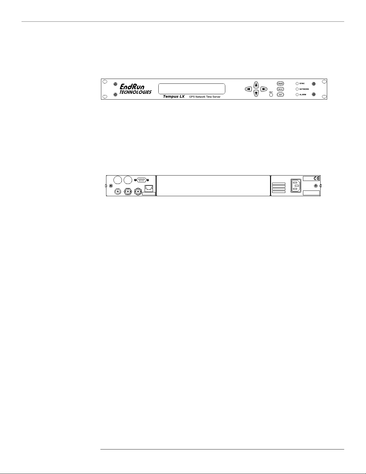
Sync LED This green LED ashes to indicate synchronization status.
Network LED This amber LED illuminates when the Tempus LX is connected to the
network and ashes when receiving or transmitting packets..
Alarm LED This red LED illuminates briey at power-up, and thereafter whenever
a serious fault condition exists.
Antenna Jack This TNC connector mates with the downlead cable from the external
antenna.
RS-232 Connector This DB-9M connector provides the RS-232 serial I/O console
interface to the Tempus LX. This console allows the user to initialize
and maintain the Tempus LX. See Chapter 6 - RS-232 Serial I/O Port
Signal Definitions for detailed information.
10/100Base-T Jack This RJ-45 connector mates with the ethernet twisted pair cable from
the network.
1PPS Jack This BNC connector provides the optional 1PPS TTL output, and is
(Option) usually labeled “SPARE”. The pulse width is normally 1 millisecond
wide when shipped from the factory but can be changed via the
front-panel keypad or via command cpuoptsconfig. See
details in Appendix H - Specifications for the 1PPS Output.
1PPS (RS-422) This optional DB-9M connector provides the 1PPS output at RS-422
(Option) levels and is usually not installed. The pulse width is normally
1 millisecond wide when shipped from the factory but can be changed
via the front-panel keypad or via command cpuoptsconfig. See
pinout details in Appendix H - Specifications for the 1PPS RS-422
Output.
AM Code Jack This BNC connector provides the optional amplitude-modulated
(Option) timecode output, and is usually labeled “SPARE”. The timecode output
is normally IRIG-B122 when shipped from the factory, but can be
changed via the front-panel keypad or via command cpuoptsconfig.
See details in Appendix H - Specifications for the AM Code Output.
4
Te m p u s L X G P S U s e r M a n u a l
Page 17

B A S I C I N S TA L L AT I O N
_
+
Alarm Jack This BNC connector (or terminal strip) provides the optional alarm
(Option) output, and is usually not installed. If installed, see details in Appendix
H - Specifications for the Alarm Output.
Prog TTL Jack This BNC connector provides the optional Programmable TTL pulse
(Option) rate output and is usually not installed. If installed, see details in
Appendix H - Specifications for the Programmable TTL output.
This pulse rate is normally shipped from the factory as 10MPPS
but can be changed via the front-panel keypad or command
cpuoptsconfig.
10MPPS or 100 PPS, etc. This BNC connector provides an optional customer-specied
(Option) rate output and is usually not installed. If installed, it will be labeled
for the appropriate rate such as “10 MPPS” or “100 PPS”, etc. This
output is set at the factory and cannot be changed. See details in
Appendix H - Specifications for the Fixed Rate Output.
Serial Time Output This optional DB-9M connector provides the RS-232 serial I/O
(Option) interface with a once-per-second ASCII time string output. For further
information refer to Appendix F - Serial Time Output.
Performing an Initial Site Survey
AC Power Input Jack This IEC 320 standard three-prong connector provides AC power.
DC Power Input Block This optional 3-position terminal block provides connection to the
DC power source, and replaces the AC power input jack.
Using the status LED indicators, it’s easy to nd out if your Tempus LX will work in your desired
location:
1. Screw the TNC plug on the end of the antenna cable onto the TNC antenna input jack on the chassis rear panel of the Tempus LX.
2. Plug one end of the supplied AC power cord into an 85-270 VAC outlet.
3. Plug the other end into the AC input connector on the chassis rear panel of the Tempus LX.
Place the antenna in a window, or for best performance, mount it on the roof using the supplied
mounting hardware. Make sure that it is not blocked by large metallic objects closer than one meter.
Although the antenna should normally be installed in a vertical orientation for rooftop installations,
when window mounting it should be pointed out the window, in the direction that gives the best clear
view to the sky. This will improve its ability to receive signals from satellites near the horizon.
Initially upon power up:
1. The unit will light the red Alarm Status LED for about ten seconds.
5
Te m p u s L X G P S U s e r M a n u a l
Page 18

C H A P T E R T W O
7
Te m p u s L X G P S U s e r M a n u a l
B A S I C I N S TA L L AT I O N
2. Then it will continuously light the green Sync Status LED.
3. When the unit locks onto a GPS signal and begins to decode the timing data and adjust the local
oscillator, the green Sync Status LED will ash very rapidly (about a 6 Hz rate) until the data is fully
decoded and the local oscillator is fully locked to the GPS frequency.
4. Then the green Sync Status LED will pulse at precisely a 1 Hz rate, synchronized to UTC seconds,
with a short on duration relative to the off duration.
At this point, the GPS time and frequency engine has fully synchronized, and you may proceed to
permanently mounting the chassis and antenna in their desired locations.
If this sequence has not occurred within twenty-four hours, and you have mounted your antenna in a
window or your rooftop installation has poor sky visibility, you may need to provide an accurate reference position to the unit so that it can operate with only one satellite in view. If you have mounted
the antenna in a window and can easily move it to the rooftop, you should do that rst. Should you
need to provide a reference position to the unit, refer to Appendix D - GPS Reference Position and
the setgpsrefpos command for details.
Installing the Tempus LX
If you are unable to achieve GPS lock after trying all of these suggestions, then your Tempus LX may
be damaged and should be returned to the factory for repair or exchange.
FCC NOTICE
This equipment has been tested and found to comply with the limits for a Class A digital device, pursuant
to part 15 of the FCC Rules. These limits are designed to provide reasonable protection against harmful
interference when the equipment is operated in a commercial environment. This equipment generates,
uses, and can radiate radio frequency energy and, if not installed and used in accordance with the instruction manual, may cause harmful interference to radio communications. Operation of this equipment in a
residential area is likely to cause harmul interference in which case the user will be required to correct the
interference at his own expense.
Mount the Tempus LX
Using standard 19” rack mounting hardware, mount the unit in the desired location. After mounting
the unit and connecting the antenna cable, verify that it still acquires and tracks a GPS signal.
CAUTION
Ground the unit properly with the supplied power cord.
Position the power cord so that you can easily disconnect it from the Tempus LX.
Do not install the Tempus LX where the operating ambient temperature might exceed 122°F (50°C).
Connecting the DC Power Option
Connect the safety ground terminal to earth ground. Connect the “+” terminal to the positive output
Te m p u s L X G P S U s e r M a n u a l
6
Page 19

B A S I C I N S TA L L AT I O N
of the DC power source. Connect the “-” terminal to the negative output of the DC power source.
Note that the Tempus LX has a “oating” internal power supply, therefore either the positive or negative output of the DC power source can be referenced to earth ground. This unit will not operate if
the +/- connections are reversed; however it will not be damaged by a reverse connection.
SHOCK/ENERGY HAZARD
Install in Restricted Access Location.
Use 10-14 AWG copper wire only.
Terminal block screw torque: 9 in-lbs (1 nM).
Branch circuit must have circuit breaker, 15A or less.
Install terminal block cover after wiring.
Connecting and Configuring Ethernet
Connect one end of the CAT-5 patch cable supplied with your Tempus LX to the rear panel mounted
RJ-45 connector labeled 10/100BASE-T. Connect the other end of the patch cable to your network
through a ‘straight’ port on your hub. Do not connect it to a ‘crossover’ port on your hub.
By factory default, the Tempus LX will attempt to congure the ethernet interface automatically via
the Dynamic Host Conguration Protocol (DHCP). The Tempus LX will attempt to set the netmask,
its IP address, the IP address of the default gateway, the domain name and the IP addresses of any
nameservers, if the DHCP server is congured to provide them. You may optionally congure the
Tempus LX to also set its hostname via DHCP, if your DHCP server is congured to provide it. You
can do this by running a simple shell script called netconfig after your unit is up on the network.
If your network does use DHCP for host conguration, and you are in a hurry to get your Tempus LX
up and running, you may procede to Verifying Network Conguration to make sure that the network
parameters were set up correctly. Otherwise, it is recommended that you read the following sections
on use of the RS-232 serial I/O port now, since they will help you in debugging any problems that
you may encounter with the automatic conguration via DHCP.
If your network does not use DHCP, you will need to congure your ethernet interface using either
the front-panel keypad or the RS-232 serial I/O port. The following sections contain brief descriptions on how to do that.
Configuring Ethernet with the Front-Panel Keypad
Conguring your ethernet interface with the front-panel keypad is quite simple. After the unit has
powered on, press the ENTER key once or twice until you see a display called Main Menu. Now
press the RIGHT arrow key until the “Network” selection is highlighted. Press ENTER again. You
will see the IP address, gateway and netmask settings displayed here. Press the EDIT key to modify
these settings. The sequence of edit displays will guide you through the setup process. Press the
HELP key at any time to view context-sensitive help information. When you are nished the unit
will reset. Skip to the section called Check Network Operation later in this chapter to continue with
the basic installation procedures.
7
Te m p u s L X G P S U s e r M a n u a l
Page 20

C H A P T E R T W O
9
Te m p u s L X G P S U s e r M a n u a l
B A S I C I N S TA L L AT I O N
Configuring Ethernet with the Serial Port
To congure your ethernet interface with the serial port, after logging in as the root user, you must
run a simple shell script called netconfig from the bash shell prompt. This shell script will prompt
you for the needed information and perform some syntax checking on your inputs. Then it will create
or modify the appropriate les needed to congure the ethernet interface. The following sections will
guide you in setting up communications with the Tempus LX using its RS-232 serial I/O port.
Connect the RS-232 Serial I/O Port
You will need to use the RS-232 serial I/O port if your network does not support the Dynamic Host
Conguration Protocol (DHCP). In that case, you must be able to congure the Tempus LX network
parameters manually using the Linux console shell interface which is provided by this serial I/O port.
Under certain conditions, you may also need to use the RS-232 serial I/O port if you encounter a
problem while upgrading the rmware in your Tempus LX.
To test serial communications with the Tempus LX you will need either a VT100 compatible terminal
or a terminal emulation program running on your computer. We will refer to either of these as “terminal” for the remainder of this instruction.
1. Disconnect power from the Tempus LX.
2. Connect one end of the DB9F-to-DB9F null modem adapter cable to the serial I/O jack on the
Tempus LX.
3. Connect the other end of the DB9F-to-DB9F null modem adapter cable to the terminal. If the
serial I/O port on your terminal does not have a DB9M connector, you may need to use an adapter.
Refer to Chapter 6 - RS-232 Serial I/O Port Signal Definitions for details on the signal wiring. If
you are using a computer for your terminal, remember which port you are using because you will
need to know that in order to set up your terminal software.
Test the Serial Port
You must congure your terminal to use the serial I/O port you used in Connect the RS-232 Serial
I/O Port. You must also congure your terminal to use the correct baud rate, number of data bits,
parity type and number of stop bits. Be sure to turn off any hardware or software handshaking. The
settings for the Tempus LX are:
• 19200 is the Baud Rate
• 8 is the number of Data Bits
• None is the Parity
• 1 is the number of Stop Bits
After conguring these parameters in your terminal, apply power to the Tempus LX. After about 20
seconds, your terminal should display a sequence of boot messages similar to these:
***************************************************
* 6010-0040-000 Linux Bootloader v1.00 08/17/2004 *
***************************************************
Default root file system: FACTORY
To override and boot the UPGRADE partition type ‘UPGRADE’ within 5 seconds...
.....
Te m p u s L X G P S U s e r M a n u a l
8
Page 21

B A S I C I N S TA L L AT I O N
These lines are the Linux bootloader boot prompt. This prompt will timeout after 5 seconds and the
Linux kernel and the factory default Tempus LX root le system will be loaded. When the Linux kernel is loaded from FLASH memory into RAM a long list of kernel-generated, informational messages
is displayed as the kernel begins execution and the various device drivers are initialized:
Booting Linux with FACTORY root file system...
6010-0041-000 Linux Kernel v2.4.26-1 #0 Wed Aug 18 17:28:45 UTC 2004
BIOS-provided physical RAM map:
BIOS-88: 0000000000000000 - 000000000009f000 (usable)
BIOS-88: 0000000000100000 - 0000000002000000 (usable)
32MB LOWMEM available.
On node 0 totalpages: 8192
zone(0): 4096 pages.
zone(1): 4096 pages.
zone(2): 0 pages.
DMI not present.
Kernel command line: config=11000001 initjffs=0 console=ttyS0,19200 root=/dev/
mtdblock4 load_ramdisk=1 rw
Initializing CPU#0
Calibrating delay loop... 66.96 BogoMIPS
Memory: 30784k/32768k available (812k kernel code, 1596k reserved, 162k data, 68k
init, 0k highmem)
Checking if this processor honours the WP bit even in supervisor mode... Ok.
Dentry cache hash table entries: 4096 (order: 3, 32768 bytes)
Inode cache hash table entries: 2048 (order: 2, 16384 bytes)
Mount cache hash table entries: 512 (order: 0, 4096 bytes)
Buffer cache hash table entries: 1024 (order: 0, 4096 bytes)
Page-cache hash table entries: 8192 (order: 3, 32768 bytes)
CPU: AMD 486 DX/4-WB stepping 04
Checking ‘hlt’ instruction... OK.
POSIX conformance testing by UNIFIX
PCI: Using configuration type 1
PCI: Probing PCI hardware
PCI: Probing PCI hardware (bus 00)
Linux NET4.0 for Linux 2.4
Based upon Swansea University Computer Society NET3.039
Initializing RT netlink socket
Starting kswapd
JFFS2 version 2.1. (C) 2001 Red Hat, Inc., designed by Axis Communications AB.
Serial driver version 5.05c (2001-07-08) with MANY_PORTS SHARE_IRQ SERIAL_PCI enabled
ttyS00 at 0x03f8 (irq = 4) is a 16550A
ttyS01 at 0x02f8 (irq = 3) is a 16550A
ttyS02 at 0x03e8 (irq = 0) is a ST16654
ttyS03 at 0x02e8 (irq = 3) is a ST16654
sc520_wdt: CBAR: 0x800df000
sc520_wdt: MMCR Aliasing enabled.
sc520_wdt: WDT driver for SC520 initialised.
RAMDISK driver initialized: 16 RAM disks of 16384K size 1024 blocksize
pcnet32.c:v1.28 02.20.2004 [email protected]
PCI: Enabling device 00:0d.0 (0000 -> 0003)
pcnet32: PCnet/FAST III 79C973 at 0x1000, 00 0e fe 00 00 33
tx_start_pt(0x0c00):~220 bytes, BCR18(9a61):BurstWrEn BurstRdEn NoUFlow
SRAMSIZE=0x1700, SRAM_BND=0x0800, assigned IRQ 12.
eth0: registered as PCnet/FAST III 79C973
pcnet32: 1 cards_found.
Tempus SC520 flash device: 1000000 at 2000000
Amd/Fujitsu Extended Query Table v1.3 at 0x0040
number of CFI chips: 1
Creating 7 MTD partitions on “Tempus SC520 Flash Bank”:
0x00000000-0x000e0000 : “Tempus kernel”
mtd: Giving out device 0 to Tempus kernel
9
Te m p u s L X G P S U s e r M a n u a l
Page 22

C H A P T E R T W O
11
Te m p u s L X G P S U s e r M a n u a l
B A S I C I N S TA L L AT I O N
0x000e0000-0x00100000 : “Tempus Lo BootLdr”
mtd: Giving out device 1 to Tempus Lo BootLdr
0x00100000-0x00200000 : “Tempus /boot”
mtd: Giving out device 2 to Tempus /boot
0x00200000-0x00300000 : “Tempus /logs”
mtd: Giving out device 3 to Tempus /logs
0x00300000-0x00900000 : “Tempus FACTORY rootfs”
mtd: Giving out device 4 to Tempus FACTORY rootfs
0x00900000-0x00fe0000 : “Tempus UPGRADE rootfs”
mtd: Giving out device 5 to Tempus UPGRADE rootfs
0x00fe0000-0x01000000 : “Tempus Hi BootLdr”
mtd: Giving out device 6 to Tempus Hi BootLdr
NET4: Linux TCP/IP 1.0 for NET4.0
IP Protocols: ICMP, UDP, TCP, IGMP
IP: routing cache hash table of 512 buckets, 4Kbytes
TCP: Hash tables configured (established 2048 bind 2048)
NET4: Unix domain sockets 1.0/SMP for Linux NET4.0.
mtdblock_open
ok
RAMDISK: Compressed image found at block 0
mtdblock_release
ok
VFS: Mounted root (ext2 filesystem).
Freeing unused kernel memory: 68k freed
INIT: version 2.76 booting
/etc/rc.d/rc.S: /bin: is a directory
mtdblock_open
ok
mtdblock_open
ok
Loading GPS
Loading Keypad/VFD
Fri Aug 20 00:53:54 2004 -0.707128 seconds
2004
Setting system time using hwclock
INIT: Entering runlevel: 3
Entering multiuser...
Attempting to configure eth0 by contacting a DHCP server...
At this point, if you do not have a DHCP server congured on your network the unit will time-out
and print these messages:
Tempus LX GPS DHCP Client was unable to find the DHCP Server!
Fix the problem and re-boot or set up static IP address
by running netconfig.
dnsdomainname: Host name lookup failure
(none)
Then these messages are printed, in either case:
Disabling IPv4 packet forwarding...
Starting daemons: syslogd klogd inetd
Starting the Network Time Protocol daemon...
Starting the SNMP daemon...
Starting the system logfile manager...
Starting the system watchdog...woof!
Starting Keypad/Display Process
During this process, the factory default TempusLXGPS_0 root le system is loaded from FLASH
disk to an 16MB ramdisk and the remainder of the boot process completes. At this point, the Tempus
LX login prompt is displayed:
Te m p u s L X G P S U s e r M a n u a l
10
Page 23

B A S I C I N S TA L L AT I O N
********************************************************************************
* Welcome to Tempus LX GPS console on: gntp.your.domain
* Tue Feb 20 2001 21:47:03 UTC
********************************************************************************
gntp login:
Here you may log in as “gntpuser” with password “Praecis” or you may log in as the “root” user
with password “endrun_1”. When logged in as “gntpuser”, you may check status information and
view log les but you will not be able to modify any system settings or view secure les. In order to
perform system setup procedures, which includes conguring the IP network settings, you must log in
as the “root” user. After correctly entering the password at this prompt,
password:
the sign on message is shown. It identies the host system as Tempus LX GPS and shows the software part number, version and build date:
Tempus LX GPS 6010-0042-000 v 1.00 Wed May 9 14:17:44 UTC 2002
Tempus LX GPS (root@gntp:~)->
This last line is the standard Tempus LX GPS shell prompt. The Tempus LX uses the bash shell,
which is the Linux standard, full-featured shell. After conguring the unit, you should change the
passwords using the gntppasswd command issued from the shell prompt.
If you do not see characters displayed by your terminal program within 30 seconds after the unit is
powered up, you must troubleshoot your setup. An incorrectly wired cable or incorrect port setting
in your terminal emulation program are the most common problems. Refer to Chapter 6 - RS-232
Serial I/O Port Signal Definitions for the signal connections for the Tempus LX.
NOTE
You must use a null-modem cable or adapter if you are connecting the Tempus LX to another computer
or other equipment configured as Data Terminal Equipment (DTE). The supplied cable is a null-modem
cable.
Once you have successfully established communications with the Tempus LX, you may procede to
conguring the network parameters. Then you can communicate with the Tempus LX over the network using telnet or ssh and synchronize your network computers to UTC using NTP.
Using netconfig to Set Up Your IP
The following is a sample transcript which illustrates the use of netconfig. The entries made by
the user are underlined and are provided purely for illustrative purposes. You must provide equivalent entries that are specic to your network. Those shown here are appropriate for a typical network
that does not use DHCP. Start the conguration process by typing netconfig at the shell prompt:
Tempus LX GPS(root@gntp)-> netconfig
*******************************************************************************
******************** Tempus LX GPS Network Configuration *********************
*******************************************************************************
* *
11
Te m p u s L X G P S U s e r M a n u a l
Page 24

C H A P T E R T W O
13
Te m p u s L X G P S U s e r M a n u a l
B A S I C I N S TA L L AT I O N
* This script will configure the TCP/IP network parameters for your *
* Tempus LX GPS. You will be able to reconfigure your system at any time *
* by typing: *
* *
* netconfig *
* *
* The settings you make now will not take effect until you restart your *
* Tempus LX GPS, so if you make a mistake, just re-run this script before *
* re-booting. *
* *
* You will be prompted to enter your network parameters now. *
* *
*******************************************************************************
*******************************************************************************
---DHCP Settings
Use a DHCP server to configure the ethernet interface? ([y]es, [n]o) n
---HOST name setting
Set the hostname of your Tempus LX GPS. Only the base
hostname is needed, not the domain.
Enter hostname: gntp
---DOMAIN name setting
Set the domain name. Do not supply a leading ‘.’
Enter domain name for gntp: your.domain
---STATIC IP ADDRESS setting
Set the IP address for the Tempus LX GPS. Example: 111.112.113.114
Enter IP address for gntp (aaa.bbb.ccc.ddd): 192.168.1.245
---DEFAULT GATEWAY ADDRESS setting
Set the default gateway address, such as 111.112.113.1
If you don’t have a gateway, just hit ENTER to continue.
Enter default gateway address (aaa.bbb.ccc.ddd): 192.168.1.241
---NETMASK setting
Set the netmask. This will look something like this: 255.255.255.0
Enter netmask (aaa.bbb.ccc.ddd): 255.255.255.248
Calculating the BROADCAST and NETWORK addresses...
Broadcast = 192.168.1.247 Network = 192.168.1.240
Your Tempus LX GPS’s current IP address, full hostname, and base hostname:
192.168.1.245 gntp.your.domain gntp
---DOMAIN NAMESERVER(S) address setting
Will your Tempus LX GPS be accessing a nameserver ([y]es, [n]o)? y
Set the IP address of the primary name server to use for domain your.domain.
Enter primary name server IP address (aaa.bbb.ccc.ddd): 192.168.1.1
Will your Tempus LX GPS be accessing a secondary nameserver ([y]es, [n]o)? y
Set the IP address of the secondary name server to use for domain your.domain.
Enter secondary name server IP address (aaa.bbb.ccc.ddd): 192.168.1.2
Te m p u s L X G P S U s e r M a n u a l
12
Page 25

B A S I C I N S TA L L AT I O N
Setting up TCP/IP...
Creating /etc/HOSTNAME...
Creating /etc/rc.d/rc.inet1...
Creating /etc/networks...
Creating /etc/hosts...
Creating /etc/resolv.conf...
*******************************************************************************
*******************************************************************************
* *
* The Tempus LX GPS network configuration has been updated. *
* *
* Please re-boot now for the changes to take effect. *
* *
*******************************************************************************
*******************************************************************************
Verify Network Configuration
If you have made changes to your network conguration using netconfig, you should shutdown the
Tempus LX and re-boot it. There are two ways to do this:
1. Cycle power to the Tempus LX.
2. Issue the shutdown with re-boot command at the shell prompt:
Tempus LX GPS(root@gntp:~)-> shutdown -r now
If you are using the RS-232 serial I/O port to communicate with the Tempus LX, you will be able to
see the kernel generated boot messages when the unit re-boots. You should note the line
Configuring eth0 as 192.168.1.245...
if you have set up a static IP address, or this line
Attempting to configure eth0 by contacting a DHCP server...
if you are using DHCP. It appears near the end of the kernel generated boot messages.
If you are using DHCP and are not using the RS-232 serial I/O port, you will have to check the
DHCP conguration information maintained by your DHCP server to determine the expected IP address and log in to the Tempus LX using telnet or ssh to verify successful DHCP conguration.
Refer to the subsequent topics in this section Using Telnet and Using SSH, for details on logging in
to the Tempus LX that way. Once you have logged in, you may perform the following checks.
If you are not using DHCP, the IP address shown should match the static IP address which you
entered during the netconfig procedure. If so, log in as “root” at the login prompt and check the
other conguration parameters using ifconfig:
Tempus LX GPS(root@gntp:~)-> ifconfig
eth0 Link encap:Ethernet HWaddr 00:0E:FE:00:00:34
inet addr: 192.168.1.245 Bcast:192.168.1.247 Mask:255.255.255.248
UP BROADCAST RUNNING MULTICAST MTU:1500 Metric:1
RX packets:3779 errors:0 dropped:0 overruns:0 frame:0
TX packets:727 errors:0 dropped:0 overruns:0 carrier:0
collisions:0 txqueuelen:100
Interrupt:5 Base address:0x300
13
Te m p u s L X G P S U s e r M a n u a l
Page 26

C H A P T E R T W O
15
Te m p u s L X G P S U s e r M a n u a l
B A S I C I N S TA L L AT I O N
lo Link encap:Local Loopback
inet addr:127.0.0.1 Mask:255.0.0.0
UP LOOPBACK RUNNING MTU:3924 Metric:1
RX packets:170 errors:0 dropped:0 overruns:0 frame:0
TX packets:170 errors:0 dropped:0 overruns:0 carrier:0
collisions:0 txqueuelen:0
Pay particular attention to the settings shown for eth0 and in particular the Mask: setting, which
should match that which is appropriate for your network. Now check the remaining conguration
parameters using route:
Tempus LX GPS(root@gntp:~)-> route
Kernel IP routing table
Destination Gateway Genmask Flags Metric Ref Use Iface
localnet * 255.255.255.248 U 0 0 0 eth0
loopback * 255.0.0.0 U 0 0 0 lo
default 192.168.1.241 0.0.0.0 UG 1 0 0 eth0
Here you are interested in the default gateway address. It should match the appropriate one for your
network. If so, then the ethernet interface of your Tempus LX has been successfully congured to
operate on your network and you are ready to check operation of the Tempus LX over the network. If
not, you should re-check your conguration and/or repeat the netconfig procedure.
If you have congured a nameserver(s) for your network, you may check that by issuing this shell
command:
Tempus LX GPS(root@gntp:~)-> cat /etc/resolv.conf
search your.domain
nameserver 192.168.1.1
nameserver 192.168.1.2
Which displays the contents of the /etc/resolv.conf le containing your domain name and the nam-
eserver IP address(es) to use for that domain.
Check Network Operation
With your Tempus LX network parameters properly congured, you are ready to test the setup using
ping from a server or workstation that is able to access the network connected to the Tempus LX.
Alternatively, you could ping one of your servers or workstations from the Tempus LX shell prompt
to test the setup.
Once you have successfully established network communications with the Tempus LX, you may
perform all maintenance and monitoring activities via telnet and ftp. The Tempus LX provides
both client and server operation using telnet. For security reasons as well as to reduce the memory
footprint in the Tempus LX, only client operation is supported using ftp.
Security conscious users will want to use ssh, the secure shell replacement for telnet, as the login
means. The companion utility, scp provides a secure replacement for ftp as a means of transferring
les to and from the Tempus LX. Both of these protocols are supported in the Tempus LX via the
OpenSSH implementations for Linux. Refer to Appendix A - Security for more information about
the secure shell protocol.
14
Te m p u s L X G P S U s e r M a n u a l
Page 27

B A S I C I N S TA L L AT I O N
Using Telnet
When establishing a telnet connection with your Tempus LX, logging in directly as root is not permitted. This is a security measure that makes it slightly more difcult to gain access by simply trying
passwords, since it is also necessary to know the name of a user. When you initiate a telnet session
with the Tempus LX, this banner will be displayed:
********************************************************************************
* Welcome to Tempus LX GPS telnet console on: gntp.your.domain
********************************************************************************
Gntp login:
Here you may log in as “gntpuser” with password “Praecis”. When logged in as “gntpuser”, you may
check status information and view log les but you will not be able to modify any system settings or
view secure les. After correctly entering the password at this prompt,
Password:
the sign on message is shown. It identies the host system as Tempus LX GPS and shows the software part number, version and build date:
Tempus LX GPS 6010-0004-000 v 1.00 Wed May 16 14:17:44 UTC 2002
Tempus LX GPS(root@gntp:~)->
This last line is the standard Tempus LX GPS shell prompt. The Tempus LX uses the bash shell,
which is the Linux standard, full-featured shell. After conguring the unit, you should change the
passwords using the gntppasswd command issued from the shell prompt.
To gain root access, you must now issue the “super user” command at the shell prompt:
Tempus LX GPS(root@gntp:~)-> su root
You will then be prompted for the password, which is “endrun_1”, and be granted root access to the
system. To leave “super user” mode, issue the shell command exit. Issuing exit again will close
the telnet session.
Using SSH
When establishing a ssh connection with your Tempus LX, logging in directly as root is permitted.
When you log in as root via a ssh session with the Tempus LX, this banner will be displayed:
********************************************************************************
* Welcome to Tempus LX GPS SSH console on: gntp.your.domain
********************************************************************************
[email protected]’s password:
Here you may log in as “root” with password “endrun_1”. After correctly entering the password the
sign on message is shown. It identies the host system as Tempus LX and shows the software part
number, version and build date:
Tempus LX GPS 6010-0042-000 v 1.00 Fri Aug 20 14:17:44 UTC 2004
Tempus LX GPS(root@gntp:~)->
This last line is the standard Tempus LX GPS shell prompt. The Tempus LX uses the bash shell,
15
Te m p u s L X G P S U s e r M a n u a l
Page 28

17
Te m p u s L X G P S U s e r M a n u a l
B A S I C I N S TA L L AT I O N
Configuring the
Network Time Protocol
C H A P T E R T W O
which is the Linux standard, full-featured shell. After conguring the unit, you should change the
passwords using the gntppasswd command issued from the shell prompt.
Issuing exit will close the ssh session.
Now that the network has been congured and tested, you may congure the operation of the NTP
server. By default, the Tempus LX is congured to respond to NTP requests from clients that may or
may not be using MD5 authentication. If the clients are using MD5 authentication, they must be congured properly with the same MD5 authentication keys as the Tempus LX. If you need to modify
the factory default Tempus LX MD5 keys (recommended) or set up broadcast/multicast operation,
then you will need to re-congure the NTP subsystem. You may perform the conguration from
either a telnet or ssh session, the front-panel keypad, or the local RS-232 console.
NOTE
If you would like to configure your server for multicast operation, configure it as you would for broadcast
operation, with the exception that you must enter this specific NTP multicast address: 224.0.1.1, when you
are prompted to enter the broadcast address.
Configuring NTP Using the Front-Panel Keypad
To congure NTP using the front-panel keypad go to the Main Menu display. Press the RIGHT arrow key until the “NTP” selection is highlighted. Press ENTER again. Press the RIGHT arrow key
to highlight “Setup” and press ENTER. From this display you can congure broadcast/multicast
mode. You can also select previously congured MD5 authentication keys from this display. However, to congure new keys you will need to run ntpconfig.
Configuring NTP Using the Network Interface or Serial Port
The following is a transcript of the question and answer conguration utility provided by ntpcon-
fig. The user entered parameters are underlined:
Tempus LX GPS(root@gntp:~)-> ntpconfig
*******************************************************************************
**********************Network Time Protocol Configuration**********************
*******************************************************************************
* *
* This script will allow you to configure the ntp.conf and ntp.keys files *
* that control Tempus LX NTP daemon operation. *
* *
* You will be able to create new MD5 authentication keys which are stored *
* in the ntp.keys file. *
* *
* You will be able to update the authentication related commands in the *
* ntp.conf file. *
* *
* You will be able to configure the “broadcast” mode of operation, with *
* or without authentication. If you supply the multicast address instead *
* of your network broadcast address, then you will be able to configure *
* the time-to-live of the multicast packets. *
* *
16
Te m p u s L X G P S U s e r M a n u a l
Page 29

B A S I C I N S TA L L AT I O N
* The changes you make now will not take effect until you re-boot the *
* Tempus LX GPS. If you make a mistake, just re-run ntpconfig prior to *
* re-booting. *
* *
* You will now be prompted for the necessary set up parameters. *
* *
*******************************************************************************
*******************************************************************************
---MD5 Keyfile Configuration
Would you like to create a new ntp.keys file? ([y]es, [n]o) y
You will be prompted for a key number (1 - 65534), then the actual key.
When you have entered all of the keys that you need, enter zero at the next
prompt for a key number.
MD5 keys may contain from 1 to 31 ASCII characters. They may not contain
SPACE, TAB, LF, NULL, or # characters!
Enter a key number (1-65534) or 0 to quit: 1
Enter the key (1-31 ASCII characters): EndRun_Technologies_LLC
Writing key number: 1 and Key: EndRun_Technologies_LLC to ntp.keys
Enter a key number (1-65534) or 0 to quit: 2
Enter the key (1-31 ASCII characters): Tempus_GPS
Writing key number: 2 and Key: Tempus_GPS to ntp.keys
Enter a key number (1-65534) or 0 to quit: 0
---NTP Authentication Configuration
Do you want authentication enabled using some or all of the keys in
the ntp.keys file? ([y]es, [n]o) y
You will be prompted for key numbers (1 - 65534), that you want NTP to
“trust”. The key numbers you enter must exist in your ntp.keys file. If you
do not want to use some of the keys in your ntp.keys file, do not enter them
here. NTP will treat those keys as “untrusted”.
Clients that use any of the “trusted” keys in their NTP polling packets will
receive authenticated replies from the Tempus LX GPS. When you have entered
all of the “trusted keys” that you need, enter zero at the next prompt for a
key number.
Enter a trusted key number (1-65534) or 0 to quit: 1
Enter a trusted key number (1-65534) or 0 to quit: 2
Enter a trusted key number (1-65534) or 0 to quit: 0
---NTP Broadcast/Multicast Configuration
Would you like to enable broadcast/multicast server operation? ([y]es, [n]o) y
Set the network broadcast/multicast address for the Tempus LX GPS to use. For
broadcast mode, this address is the all 1’s address on the sub-net.
Example: 111.112.113.255
For multicast operation, it is this specific address: 224.0.1.1
Enter IP address for NTP broadcast/multicast operation (aaa.bbb.ccc.ddd): 224.0.1.1
17
Te m p u s L X G P S U s e r M a n u a l
Page 30

C H A P T E R T W O
You have selected multicast operation. Enter the number of hops that
are needed for the multicast packets on your network (positive integer): 1
It is highly recommended that authentication be used if you are using NTP in
broadcast/multicast mode. Otherwise clients may easily be “spoofed” by a fake NTP
server. You can specify an MD5 key number that the Tempus LX GPS will use in its
broadcast/multicast packets. The clients on your network must be configured to use
the same key.
Would you like to specify an MD5 key number to use with
broadcast mode? ([y]es, [n]o) y
Enter the MD5 key number to use (1-65534): 2
*******************************************************************************
*******************************************************************************
* *
* The Tempus LX GPS Network Time Protocol configuration has been updated. *
* *
* Please re-boot now for the changes to take effect. *
* *
*******************************************************************************
*******************************************************************************
Configuring the Tempus LX as a Stratum 2 Server
Operating the Tempus LX as a Stratum 1 Server is the recommended mode. You may operate the unit
as a Stratum 2 server but since there are innumerable ways to congure your network with Stratum 2
servers, specic insructions for how to do that are beyond the scope of this manual. General instructions are that you need to edit the etc/ntp.conf le and then copy it to the /boot/etc directory to make it
nonvolatile.
We advise against using your Tempus LX as anything other than a Stratum 1 server unless you are
knowledgeable about NTP and understand the ramications. Since the Tempus LX is running standard NTP compiled from the reference distribution all information in the following link is pertinent:
http://www.ntp.org.
Although all the information is available at the above site, the following are excellent tutorials on setting up NTP and are easier to understand:
http://www.sun.com/solutions/blueprints/0701/NTP.pdf
http://www.sun.com/solutions/blueprints/0801/NTPpt2.pdf
http://www.sun.com/solutions/blueprints/0901/NTPpt3.pdf
18
Te m p u s L X G P S U s e r M a n u a l
Page 31

"Smarter Timing Solutions"
Chapter
Three
Setting Up NTP Clients on Unix-like Platforms
To congure your Unix-like computer to use your Tempus LX, you must have successfully completed
the Basic Installation procedures in Chapter 2. This manual is not a ‘How-To’ on installing and
using NTP; basic approaches to NTP client conguration for operation with the Tempus LX will be
described. It is expected that you are, or have access to, a capable Unix/Linux system administrator and know more than a little about installing distributions from source code. Installation must be
performed by a user with root priviledges on the system. If you have never used NTP, then you should
spend some time reading the on-line documents, especially the Distribution Notes, FAQ and Conguration subject matter, which are available at: http://www.ntp.org
Although all the information is available at the above site, the following are excellent tutorials on setting up NTP and are easier to understand:
http://www.sun.com/solutions/blueprints/0701/NTP.pdf
http://www.sun.com/solutions/blueprints/0801/NTPpt2.pdf
http://www.sun.com/solutions/blueprints/0901/NTPpt3.pdf
If you have a news service, many problems may be solved by the helpful people who participate in
the Internet news group devoted to NTP at comp.protocols.time.ntp.
Three methods of using the Tempus LX with NTP clients on Unix-like platforms will be described:
Basic: This is the simplest, and will operate without MD5 authentication. NTP beginners should
always perform this setup rst.
MD5: This method is trickier only because MD5 keys must be set up and distributed accurately to
the NTP clients in a secure way. The Tempus LX is factory congured to authenticate
its replies to NTP MD5 clients using its default set of keys.
Broadcast/Multicast: This method simplies conguration of the clients on large networks since
specic server addresses need not be congured in each client’s /etc/ntp.conf le. It can be congured either with or without MD5 authentication. However, it is highly recommended that authentication be congured when using broadcast/multicast mode due to the relative ease with which a fake
NTP server can take over the clock setting of the broadcast/multicast clients on the network.
19
Te m p u s L X G P S U s e r M a n u a l
Page 32

21
Te m p u s L X G P S U s e r M a n u a l
S E T T I N G U P N TP C L I E N T S O N U N I X - L I KE P L AT F O R M S
Basic NTP Client Setup
C H A P T E R T H R E E
Basic setup is relatively simple, if:
• You have been able to successfully communicate with the Tempus LX on your network.
• You have installed NTP on your client computer.
Configure NTP
You must edit the ntp.conf le which ntpd, the NTP daemon, looks for by default in the the /etc
directory. Add this line to the ntp.conf le:
server 192.168.1.245
This line tells ntpd to use the NTP server at address 192.168.1.245 in addition to any other servers
which might also be congured in the client’s ntp.conf le.
Re-start ntpd to have it begin using the Tempus LX server. Use the NTP utility ntpq to check that
ntpd is able to communicate with the Tempus LX. After issuing the command
MD5 Authenticated NTP Client Setup
ntpq
you will see the ntpq command prompt:
ntpq>
Use the command
peers
to display the NTP peers which your computer is using. One of them should be the Tempus LX
server which you have just congured. You should verify that it is being ‘reached’. (You may have
to continue issuing the peers command for a minute or two before you will see the ‘reach’ count
increment.) If you have other peers congured, verify that the offset information for the Tempus LX
server peer and your other peers is in agreement to within a few milliseconds, assuming that the other
peers are synchronized to that level of accuracy.
It may also be useful to start the NTP daemon in ‘debug’ mode (ntpd -d) to conrm successful
conguration. Refer to the NTP documentation for detailed usage of these debug utilities.
MD5 authenticated setup is relatively simple, if:
• You have been able to successfully communicate with the Tempus LX on your network.
• Your Tempus LX has been congured to perform authentication either by factory default, or by
running the ntpconfig shell script. The example Tempus LX authentication conguration shown in
Chapter 2 - Configuring the Network Time Protocol will be assumed in the example conguration
commands shown here.
• You have installed NTP on your client computer.
Te m p u s L X G P S U s e r M a n u a l
20
Page 33

S E T T I N G U P N TP C L I E N T S O N U N I X - L I KE P L AT F O R M S
• You have successfully performed the Basic NTP Client Setup on your client computer.
Create the ntp.keys File
You must create a le named ntp.keys in the /etc directory. It must be a copy of the one residing in
the /etc directory of your Tempus LX. You can telnet into your Tempus LX and start an ftp session with your client computer to send the Tempus LX’s /etc/ntp.keys le to your client computer,
use the secure copy utility scp, or you can just use a text editor on your client computer to create an
equivalent le.
IMPORTANT
Handling of the /etc/ntp.keys file is the weak link in the MD5 authentication scheme. It is very important that it is owned by root and not readable by anyone other than root.
After transferring the le by ftp, and placing it in the /etc directory on the client computer, issue
these two commands at the shell prompt:
chown root.root /etc/ntp.keys
chmod 600 /etc/ntp.keys
Configure NTP
You must edit the ntp.conf le which ntpd, the NTP daemon, looks for by default in the /etc directory. Assuming that you have created two trusted keys as shown in the example in the previous chapter,
add these lines to the end of the ntp.conf le:
keys /etc/ntp.keys
trustedkey 1 2
Modify the line added previously in Basic NTP Client Setup so that authentication will be used with
the Tempus LX server using one of the trusted keys, in this case key # 1:
server 192.168.1.245 key 1
Re-start ntpd to have it begin using the Tempus LX server with MD5 authentication. Use the NTP
utility ntpq to check that ntpd is able to communicate with the Tempus LX. After issuing the command
ntpq
you will see the ntpq command prompt:
ntpq>
Use the command
peers
to display the NTP peers which your computer is using. One of them should be the Tempus LX
server which you have just congured. You should verify that it is being ‘reached’. (You may have
to continue issuing the peers command for a minute or two before you will see the ‘reach’ count
increment.)
21
Te m p u s L X G P S U s e r M a n u a l
Page 34

23
Te m p u s L X G P S U s e r M a n u a l
S E T T I N G U P N TP C L I E N T S O N U N I X - L I KE P L AT F O R M S
Broadcast/Multicast NTP Client Setup
C H A P T E R T H R E E
You can verify that authentication is being used by issuing the command
associations
to display the characteristics of the client server associations. In the “auth” column of the display,
you should see “OK” for the row corresponding to the Tempus LX server. If you see “bad”, you
should wait a few minutes to be sure that there is a problem since “bad” is the initial state of this
setting. If the “bad” indication persists then you must check your conguration for errors. Typically this is due to a typing error in creating the /etc/ntp.keys le on the client that causes a mismatch
between the keys being used by the server and client. (If you transfer the le by ftp or scp, this
shouldn’t be a problem.) It is also possible to have a typing error in the /etc/ntp.conf le that causes
the needed key to not be included in the “trustedkey” list.
Broadcast/multicast client setup is relatively simple, if:
• You have been able to successfully communicate with the Tempus LX on your network.
• Your Tempus LX has been congured to perform broadcasts or multicasts via the front-panel
keypad or by running the ntpconfig shell script. (This is not the factory default conguration, so
be sure to run ntpconfig.) If you are going to use MD5 authentication, your Tempus LX must have
been congured to operate with authentication in the broadcast/multicast mode, and you must know
which of the trusted keys it is using for broadcast/multicast operation. The example Tempus LX
conguration shown in Chapter 2 - Configuring the Network Time Protocol will be assumed in the
example conguration commands shown here.
• You have installed NTP on your client computer.
• You have successfully performed the MD5 Authenticated NTP Client Setup on your client computer, if you plan to use MD5 authentication.
Configure NTP
You must edit the ntp.conf le which ntpd, the NTP daemon, looks for by default in the the /etc
directory. Assuming that your Tempus LX server has been congured to use key 2 for broadcast
authentication as shown in the example in chapter 2, make sure that key 2 is included in the trust-
edkey line, and add this line to the end of the ntp.conf le:
broadcastclient
If you are not using MD5 authentication, you would add these lines:
disable auth
broadcastclient
If you are using multicast instead of broadcast mode, you would replace the broadcastclient
keyword with the multicastclient keyword. You may remove the line added previously in Basic
NTP Client Setup:
server 192.168.1.245
Te m p u s L X G P S U s e r M a n u a l
22
Page 35

S E T T I N G U P N TP C L I E N T S O N U N I X - L I KE P L AT F O R M S
or the authenticated version added in MD5 Authenticated NTP Client Setup:
server 192.168.1.245 key 1
Re-start ntpd to have it begin using the Tempus LX as a broadcast or multicast server. Use the NTP
utility ntpq to check that ntpd is able to communicate with the Tempus LX. After issuing the command
ntpq
you will see the ntpq command prompt:
ntpq>
Use the command
peers
to display the NTP peers which your computer is using. One of them should be the Tempus LX
server which you have just congured. You should verify that it is being ‘reached’. (You may have
to continue issuing the peers command for a minute or two before you will see the ‘reach’ count
increment.)
If you are using authentication, you can verify that authentication is being used by issuing the command
associations
to display the characteristics of the client server associations. In the “auth” column of the display,
you should see “OK” for the row corresponding to the Tempus LX server. If you see “bad”, you
should wait a few minutes to be sure that there is a problem since “bad” is the initial state of this
setting. If the “bad” indication persists then you must check your conguration for errors. Typically this is due to a typing error in creating the /etc/ntp.keys le on the client that causes a mismatch
between the keys being used by the server and client. (If you transfer the le by ftp or scp, this
shouldn’t be a problem.) It is also possible to have a typing error in the /etc/ntp.conf le that causes
the needed key to not be included in the “trustedkey” list.
23
Te m p u s L X G P S U s e r M a n u a l
Page 36

C H A P T E R T H R E E
24
Te m p u s L X G P S U s e r M a n u a l
Page 37

"Smarter Timing Solutions"
Chapter
Four
Setting Up NTP Clients on Windows NT 4.0/2000/XP
To congure your Windows NT 4.0/2000/XP computer to use your Tempus LX, you must have successfully completed the Basic Installation procedures in Chapter 2. This manual is not a ‘How-To’ on
installing and using NTP; basic approaches to NTP conguration for operation with the Tempus LX
will be described here. Installation must be performed by a user with administrative priviledges on
the system. If you have never used NTP, then you should spend some time reading the on-line documents at: http://www.ntp.org.
Although all the information is available at the above site, the following are excellent tutorials on setting up NTP and are easier to understand:
http://www.sun.com/solutions/blueprints/0701/NTP.pdf
http://www.sun.com/solutions/blueprints/0801/NTPpt2.pdf
http://www.sun.com/solutions/blueprints/0901/NTPpt3.pdf
If you have a news service, many problems may be solved by the helpful people who participate in
the Internet news group devoted to NTP at comp.protocols.time.ntp.
Three methods of using the Tempus LX with NTP clients on Window NT 4.0 platforms will be described:
Basic: This is the simplest, and will operate without MD5 authentication. NTP beginners
should always perform this setup rst.
MD5: This method is trickier only because MD5 keys must be set up and distributed accurately to
the NTP clients in a secure way. The Tempus LX is factory congured to authenticate its replies to
NTP MD5 clients using its default set of keys.
Broadcast/Multicast: This method simplies conguration of the clients on large networks since
specic server addresses need not be congured in each client’s \winnt\system32\drivers\etc\ntp.conf
le. It can be congured either with or without MD5 authentication. However, it is highly recommended that authentication be congured when using broadcast /multicast mode due to the relative
ease with which a fake NTP server can take over the clock setting of the broadcast/multicast clients
on the network.
25
Te m p u s L X G P S U s e r M a n u a l
Page 38

27
Te m p u s L X G P S U s e r M a n u a l
S E T T I N G U P N TP C L I E N T S O N W I N D O W S N T 4 . 0 / 2 0 0 0 / XP
Basic NTP Client Setup
C H A P T E R F O U R
Basic setup is relatively simple, if:
• You have been able to successfully communicate with the Tempus LX on your network.
• You have installed NTP on your client computer.
Configure NTP
You must edit the ntp.conf le which ntpd.exe, the NTP daemon, looks for by default in the the
\winnt\system32\drivers\etc directory of the boot partition. If your NTP installation placed this le in
a different place, you must nd it and edit it. For example, XP uses \windows\system32\drivers\etc.
Add this line to the ntp.conf le:
server 192.168.1.245
This line tells ntpd.exe to use the NTP server at address 192.168.1.245 in addition to any other
servers which might also be congured in the ntp.conf le.
Re-start ntpd.exe to have it begin using the Tempus LX server. By default, the NTP installation
program installs ntpd.exe as a service called Network Time Protocol, and starts it. You must use
the Services utility in Control Panel to stop the Network Time Protocol service and then re-start it.
Use the NTP utility ntpq.exe to check that ntpd.exe is able to communicate with the Tempus LX.
By default it is installed in the \Program Files\Network Time Protocol sub-directory of your Windows
NT/2000/XP partition. From a console window, after issuing the command
ntpq
you will see the ntpq.exe command prompt:
ntpq>
Use the command
peers
to display the NTP peers which your computer is using. One of them should be the Tempus LX
server which you have just congured. You should verify that it is being ‘reached’. (You may have
to continue issuing the peers command for a minute or two before you will see the ‘reach’ count
increment.) If you have other peers congured, verify that the offset information for the Tempus LX
server peer and your other peers is in agreement to within a few milliseconds, assuming that the other
peers are synchronized to that level of accuracy.
It may also be useful to start the NTP daemon in ‘debug’ mode (ntpd -d) to conrm successful conguration. The debug version of the NTP daemon is located in the debug sub-directory of your NTP
directory. Refer to the NTP documentation for detailed usage of these debug utilities.
Te m p u s L X G P S U s e r M a n u a l
26
Page 39

MD5 Authenticated NTP Client Setup
S E T T I N G U P N TP C L I E N T S O N W I N D O W S N T 4 . 0 / 2 0 0 0 / XP
MD5 authenticated setup is relatively simple, if:
• You have been able to successfully communicate with the Tempus LX on your network.
• Your Tempus LX has been congured to perform authentication either by factory default, or by
running the ntpconfig shell script. The example Tempus LX authentication conguration shown in
Chapter 2 - Configuring the Network Time Protocol will be assumed in the example conguration
commands shown here.
• You have installed NTP on your client computer.
• You have successfully performed the Basic NTP Client Setup on your client computer.
Create the ntp.keys File
You must create a le named ntp.keys in the \winnt\system32\drivers\etc directory or, for XP, the
\windows\system32\drivers\etc directory. It must be a copy of the one residing in the /etc directory of
your Tempus LX. You can telnet into your Tempus LX and start an ftp session with your client
computer to send the Tempus LX /etc/ntp.keys le to your client computer, or use the secure copy
utility scp, or use a text editor to create the equivalent le. Although you should rst test your setup
using the factory default /etc/ntp.keys le in your Tempus LX server, you should create your own
keys after you understand the process and have your clients operating correctly with the default le.
IMPORTANT
Handling of the \windows\system32\drivers\etc\ntp.keys file is the weak link in the MD5 authentication scheme. It is very important that it is owned by “administrator” and not readable by anyone other
than “administrator”.
After transferring the file, make sure that its security properties are set such that it is readable only by the
“administrator”.
Configure NTP
You must edit the ntp.conf le which ntpd.exe, the NTP daemon, looks for by default in the the
\winnt\system32\drivers\etc directory. If your NTP installation placed this le in a different place,
you must nd it and edit it. For example, XP uses \windows\system32\drivers\etc. Add these lines to
the end of the ntp.conf le:
keys \winnt\system32\drivers\etc\ntp.keys
trustedkey 1 2
Modify the line added previously in Basic NTP Client Setup so that authentication will be used with
the Tempus LX server using one of the trusted keys, in this case key # 1:
server 192.168.1.245 key 1
27
Te m p u s L X G P S U s e r M a n u a l
Page 40

C H A P T E R F O U R
29
Te m p u s L X G P S U s e r M a n u a l
S E T T I N G U P N TP C L I E N T S O N W I N D O W S N T 4 . 0 / 2 0 0 0 / XP
Re-start ntpd.exe to have it begin using the Tempus LX server with MD5 authentication. By default, the NTP installation program installs ntpd.exe as a service called Network Time Protocol, and
starts it. You must use the Services utility in Control Panel to stop the Network Time Protocol service
and then re-start it.
Use the NTP utility ntpq.exe to check that ntpd.exe is able to communicate with the Tempus LX.
By default it is installed in the \Program Files\Network Time Protocol sub-directory of your Windows
NT/2000/XP partition. From a console window, after issuing the command
ntpq
you will see the ntpq.exe command prompt:
ntpq>
Use the command
peers
to display the NTP peers which your computer is using. One of them should be the Tempus LX
server which you have just congured. You should verify that it is being ‘reached’. (You may have
to continue issuing the peers command for a minute or two before you will see the ‘reach’ count
increment.)
Broadcast/Multicast NTP Client Setup
You can verify that authentication is being used by issuing the command
associations
to display the characteristics of the client server associations. In the “auth” column of the display,
you should see “OK” for the row corresponding to the Tempus LX server. If you see “bad”, you
should wait a few minutes to be sure that there is a problem since “bad” is the initial state of this
setting. If the “bad” indication persists then you must check your conguration for errors. Typically
this is due to a typing error in creating the \winnt\system32\drivers\etc\ntp.keys le on the client that
causes a mismatch between the keys being used by the server and client. (If you transfer the le
by ftp or scp, this shouldn’t be a problem.) It is also possible to have a typing error in the \winnt\
system32\drivers\etc\ntp.conf le that causes the needed key to not be included in the “trustedkey”
list.
Broadcast/multicast client setup is relatively simple, if:
• You have been able to successfully communicate with the Tempus LX on your network.
• Your Tempus LX has been congured to perform broadcasts or multicasts via the front-panel keypad or by running the ntpconfig shell script. (This is not the factory default conguration, so be
sure to run ntpconfig.) If you are going to use MD5 authentication, your Tempus LX must have
been congured to operate with authentication in the broadcast/multicast mode, and you must know
which of the trusted keys it is using for broadcast/multicast operation. The example Tempus LX
conguration shown in Chapter 2 - Configuring the Network Time Protocol will be assumed in the
example conguration commands shown here.
28
Te m p u s L X G P S U s e r M a n u a l
Page 41

S E T T I N G U P N TP C L I E N T S O N W I N D O W S N T 4 . 0 / 2 0 0 0 / XP
• You have installed NTP on your client computer.
• You have successfully performed the MD5 Authenticated NTP Client Setup on your client computer, if you plan to use MD5 authentication.
Configure NTP
You must edit the ntp.conf le which ntpd.exe, the NTP daemon, looks for by default in the the
\winnt\system32\drivers\etc directory or, for XP, the \windows\system32\drivers\etc directory. As-
suming that your Tempus LX server has been congured to use key 2 for broadcast authentication as
shown in the example in chapter 2, make sure that key 2 is included in the trustedkey line, and add
this line to the end of the ntp.conf le:
broadcastclient
If you are not using MD5 authentication, you would add these lines:
disable auth
broadcastclient
If you are using multicast instead of broadcast mode, you would replace the broadcastclient
keyword with the multicastclient keyword. You may remove the line added previously in Basic
NTP Client Setup:
server 192.168.1.245
or the authenticated version added in MD5 Authenticated NTP Client Setup:
server 192.168.1.245 key 1
Re-start ntpd.exe to have it begin using the Tempus LX as a broadcast or multicast server. By default, the NTP installation program installs ntpd.exe as a service called Network Time Protocol, and
starts it. You must use the Services utility in Control Panel to stop the Network Time Protocol service
and then re-start it.
Use the NTP utility ntpq.exe to check that ntpd.exe is able to communicate with the Tempus LX.
By default it is installed in the \Program Files\Network Time Protocol sub-directory of your Windows
NT/2000/XP partition. After issuing the command
ntpq
you will see the ntpq.exe command prompt:
ntpq>
Use the command
peers
to display the NTP peers which your computer is using. One of them should be the Tempus LX
server which you have just congured. You should verify that it is being ‘reached’. (You may have
to continue issuing the peers command for a minute or two before you will see the ‘reach’ count
increment.)
29
Te m p u s L X G P S U s e r M a n u a l
Page 42

C H A P T E R F O U R
If you are using authentication, you can verify that authentication is being used by issuing the command
associations
to display the characteristics of the client server associations. In the “auth” column of the display,
you should see “OK” for the row corresponding to the Tempus LX server. If you see “bad”, you
should wait a few minutes to be sure that there is a problem since “bad” is the initial state of this
setting. If the “bad” indication persists then you must check your conguration for errors. Typically this is due to a typing error in creating the \windows\system32\drivers\etc\ntp.keys le on the
client that causes a mismatch between the keys being used by the server and client. (If you transfer
the le by ftp or scp, this shouldn’t be a problem.) It is also possible to have a typing error in
the \windows\system32\drivers\etc\ntp.conf le that causes the needed key to not be included in the
“trustedkey” list.
30
Te m p u s L X G P S U s e r M a n u a l
Page 43

"Smarter Timing Solutions"
Display Description
Keypad Description
Chapter
Five
Front-Panel Keypad and Display
This section describes the Tempus LX front-panel user interface which consists of a graphic vacuumuorescent display (VFD) and keypad. The keypad and display provide a convenient interface that
allows the user to quickly check the operation of the instrument and setup many control parameters.
If desired, the Network Administrator can disable the keypad EDIT key to prevent unauthorized tampering with the instrument setup. Even when disabled, all status and control parameters are available for reading only.
The display consists of a graphic 16 x 280 dot-matrix vacuum-uorescent array. The VFD technology
offers very readable alphanumeric characters with variable font sizes. Time information is readable
at distances in excess of 15 feet. The keypad consists of an eight-key switch assembly designed to
allow easy parameter selection and control.
The front-panel keypad consists of eight switch keys identied as follows:
ENTER: Select a menu item or load a parameter when editing.
BACK: Return to previous display or abort an edit process.
EDIT: Edit the parameter currently in view.
HELP: Display context-sensitive help information.
LEFT arrow: Select a new item to the left.
RIGHT arrow: Select a new item to the right.
DOWN arrow: Scroll through parameter values in edit displays or through help lines in help
displays. In all other displays this key has a secondary function where it will
operate like the ENTER key to select menu items.
UP arrow: Scroll through parameter values in edit displays or through help lines in help
displays. In all other displays this key has a secondary function where it will
operate like the BACK key to return to the previous display.
31
Te m p u s L X G P S U s e r M a n u a l
Page 44
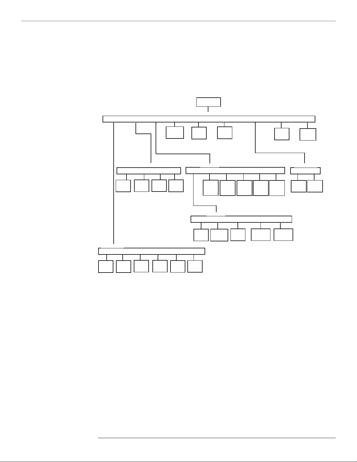
33
Te m p u s L X G P S U s e r M a n u a l
F R O N T- P A N E L K E Y PA D A N D D I S P L A Y
Display and Keypad
Time / Status
Display
Receiver Clock Opt-I/O Display Faults Network NTP Firmware About
Main Menu
System
Fault
Status
Network
Address
Setup
Program
Revision
Contact
Information
Display
Intensity /
ScreenSave
Status Ref-Pos GPS Mode Osc-Stat AntFltMask SigFltMask
Receiver Menu
GPS
Receiver
Status
Reference
Position
Status Setup
NTP Menu
NTP
Operation
Status
Broadcast
Multicast
Setup
Time-Mode Loc-Offset Hrs-Disp DST
Clock Menu
Time
Mode
Setup
Local
Offset
Setup
Hours
Display
Form
at
Daylight
Savings
Setup
GPS
Dynamic
Mode
Oscillator
Status
CPU-I/O OptCard1 OptCard2 OptCard3 OptCard4 OptCard5
Option I/O Menu
Slot5
Plug-in
Option
Info/Setup
Slot4
Plug-in
Option
Info/Setup
Slot3
Plug-in
Option
Info/Setup
Slot2
Plug-in
Option
Info/Setup
Slot1
Plug-in
Option
Info/Setup
PPS-Setup Code-Out ProgTTL Syntheszr SerTimeOut
CPU Module I/O Menu
1PPS
Pulse
Width
Time Code
Output
Fo
rmat
Prog TTL
Output
Selection
Synthesizer
Rate
Selection
Antenna
Fault
Mask
Signal
Fault
Mask
Serial
Time
Fo
rmat
Operation
C H A P T E R F I V E
The display is organized like the inverted tree structure shown below:
Traversing the Display Structure
After power initialization the welcome message will appear. Press any key to go to the Time/Status
display, which is described under the heading Detailed Display Descriptions. From the Time/Sta-
tus display, press ENTER (or DOWN arrow) to go to the Main Menu. As illustrated in the diagram
above, several status and setup displays are accessible from the Main Menu. To traverse downward
through the tree use the RIGHT and LEFT arrow keys to highlight a selection and then press ENTER.
To traverse back up the tree press BACK (or UP arrow) to return to the previous display.
Editing
To modify a parameter, traverse to the appropriate display and push EDIT. This will cause the edit
display to appear. Within the edit display, the modiable parameter value is highlighted. Use UP and
DOWN to scroll through all the possible parameter values. When editing a sequence of numbers,
use LEFT and RIGHT to select other digits. When the parameter is correct, press ENTER to load the
new value. All entered values are stored in non-volatile FLASH and restored after a power cycle. If
you wish to abort the edit process, press BACK. This operation returns you to the previous display
and the parameter will remain unchanged.
32
Te m p u s L X G P S U s e r M a n u a l
Page 45

F R O N T- P A N E L K E Y PA D A N D D I S P L A Y
12 : 59 : 45
U
T
C
Stratum- 1
Sys Stat- OK
Jul 15, 2003
Receiver- Locked
Keypad EDIT Lockout
As a security feature, the Network Administrator can disable all editing processes done through the
front-panel keypad. This action should be performed to prevent unauthorized modication of the
instrument. When the EDIT key has been disabled, a warning message will appear whenever a user
tries to edit a parameter. To enable the lockout feature use the lockoutkp command as described
in Chapter 6 - Control and Status Commands. The lockout feature will prevent editing only, the
displays are always available for viewing.
Using Help
Press HELP at any time to read the context-sensitive help messages. Most Help messages have much
more information than can be viewed within the two-line display. Use UP and DOWN to scroll
through the help message. Press the HELP key a second time to exit Help (or press BACK).
Shortcut Menu
The Shortcut Menu allows the user quick access to particular displays from the Time/Status display.
The displays available through the Shortcut Menu are the Receiver Status display, the Faults display,
and the NTP Status display. To select the Shortcut Menu, press ENTER for one second while viewing the Time/Status display.
Detailed Display Descriptions
Time/Status
The Time/Status display provides all the information necessary to determine that the instrument is
working correctly:
Time-of-Day: The large numeric digits shown on the left side of the display indicate the
current time-of-day.
Time Mode: The indicator next to the time digits identies the time mode as being UTC, GPS
or LOC (for local time). If the user selects local time in the 12-hour mode, an
AM or PM indicator will appear instead of LOC.
Date: Current month, day and year.
Stratum: The stratum eld has three possible values:
Stratum 1: The server is fully synchronized and accurate.
Stratum 2: The server is synchronized to a stratum 1 server.
Stratum 16: The server is unsynchronized. NTP clients will not use a
Stratum 16 server.
Receiver Status: GPS receiver status as follows:
Acquire: Searching for a signal.
Locking: Locking to the GPS signal.
Locked: Fully synchronized to signal.
33
Te m p u s L X G P S U s e r M a n u a l
Page 46

C H A P T E R F I V E
35
Te m p u s L X G P S U s e r M a n u a l
F R O N T- P A N E L K E Y PA D A N D D I S P L A Y
181 : 12 : 59 : 45
U
T
C
Sys Stat- OK
Receiver- Locked
Rcvr State - Locked TFOM - 4
GPS RECEIVER STATUS
MORE
Satellite ID# - 25, 03, 11, 14, 23, 31, 25, 28
Carrier / Noise - 34.5
MORE
System Status: Indicates either OK or ashing FAULT. A fault status indicates that one or more
of the built-in fault checking processes has detected an error condition. See
Faults Display in this chapter for more information.
An alternate Time/Status display can be viewed by pressing the right arrow key. You can go back to
the original Time/Status display by pressing the left arrow key.
Main Menu
Press ENTER from the Time/Status display to select the Main Menu display. The Main Menu provides access to the following displays: Receiver, Clock, CPU-I/O, Display, Faults, Network, NTP,
Firmware, and About. To select one of these items use the RIGHT and LEFT keys to highlight it.
Then push ENTER to select the highlighted item. These displays are described in detail below.
Receiver Menu
The Receiver Menu is selected from the Main Menu and provides access to the Receiver Status, Oscillator Status, Reference Position, and GPS Dynamic Mode displays described below.
Receiver Status
This display provides information associated with the operation of the GPS receiver. Press DOWN to
scroll through all the information.
Receiver State: This shows the current state of the GPS receiver subsystem. The state may be:
acquire, locking, or locked. When locked, the GPS receiver is synchronized to
the signal and it is disciplining the internal oscillator to remove frequency and
time errors.
TFOM: A detailed explanation of TFOM is in Appendix E - Time Figure-of-Merit.
Briey, TFOM indicates clock accuracy where:
4 time error is < 1 us
5 time error is < 10 us
6 time error is < 100 us
7 time error is < 1 ms
8 time error is < 10 ms
9 time error is > 10 ms, unsynchronized state if never locked to GPS.
34
Te m p u s L X G P S U s e r M a n u a l
Page 47

F R O N T- P A N E L K E Y PA D A N D D I S P L A Y
Carrier-to-Noise: The carrier-to-noise ratio is an indicator of the GPS signal quality. This
number typically ranges from 30 to 45 dB when the instrument is locked.
Satellite ID#: This eld lists the satellites that are currently being tracked.
Reference Position
This display shows the current GPS position and allows you to enter a position, if desired. The GPS
reference position is the position of the GPS receiver antenna. Accurate position is necessary to generate precise time and frequency outputs.
The source eld (SRC) indicates the source of the position information. Possible values are “unknown”, “average” and “user”. When rst installed, the position source will be “unknown”. It
changes to “average” after the receiver has computed the rst 3-dimensional position x. The position continues to be averaged for about 24 hours. Computation requires that a minimum of 4 or
more satellites be in view. The position is shown as latitude, longitude and elevation. Latitude and
longitude are shown as hemisphere (North, South, East, West), degrees, minutes and seconds. Elevation is shown in meters above the WGS-84 ellipsoid.
With a rooftop antenna installation that has an unobscured view of the sky, the instrument will determine position automatically. Once determined, the position information is saved in non-volatile
FLASH and will be restored after a power outage. After position has been determined, the instrument
can achieve time lock with only one satellite.
In some situations, visibility of the sky is limited and the unit may not be able to determine its position. In this case the user must determine an accurate WGS-84 position by other means and input it
either through the serial interface or via the front panel. In addition to loading a new accurate reference position, the user can also invalidate an existing one by setting the position source to unknown.
This will force the instrument to re-establish a new reference position using the GPS satellite constellation. Push the EDIT key to start the process. First, select the reference position source:
Unknown: Selecting “unknown” will cause the CALCULATE NEW POSITION AVERAGE
conrmation display to appear. Select YES. The front panel will return to the GPS
Reference Position display. This action will force the unit to re-establish a new reference
position. Once the receiver has computed a new accurate reference position the position
source will change from “unknown” to “average”.
User: Selecting “user” will allow you to enter a position. It is very important that the new
reference position be accurate. Refer to Appendix D - GPS Reference Position for
detailed instructions on how to obtain an accurate reference position for your location.
GPS Dynamic Mode
The GPS dynamic mode setting affects the position value used by the system to derive accurate time
synchronization. In dynamic mode, the average position is the current position, i.e. there is no postion averaging. Set the mode to “static” when the instrument is in a static installation. Set the mode
to “dynamic” if the instrument is installed on a moving platform such as a ship or aircraft.
Oscillator Status
This display provides the oscillator type and electronic frequency control status. The oscillator
control DAC value indicates the frequency control setting. The system automatically sets this value
to remove frequency errors. Values may range from 0 to 65,535. Values less than 10,000 or greater
35
Te m p u s L X G P S U s e r M a n u a l
Page 48

C H A P T E R F I V E
37
Te m p u s L X G P S U s e r M a n u a l
F R O N T- P A N E L K E Y PA D A N D D I S P L A Y
than 55,000 will set the DAC fault ag that will appear in the fault status display. The Time/Status
display will also indicate a fault condition.
The oscillator type indicates the oscillator that is installed. Possible oscillator types are:
Temperature-compensated crystal oscillator (TCXO)
Medium-stability oven oscillator (MS-OCXO)
High-stability oven oscillator (HS-OCXO)
Rubidium oscillator (Rb)
Antenna Fault Mask
This setting allows you to prevent the antenna fault from creating an alarm conditon. Some installations may need to mask this fault due to special antenna situations like splitters or DC blocks that
confuse the antenna detection circuit.
Signal Loss Fault Mask
This setting allows you to prevent a signal loss fault from creating an alarm condition. Some installations may need to mask this fault when operating the NTP server as a Stratum 2 server.
Clock Menu
The Clock Menu provides access to the parameters related to timekeeping. These are Time Mode,
Local Offset, Hours Format, and Daylight Savings Time. These displays are all described below.
Time Mode
Time mode denes the time format used for the front-panel time display and, if installed, the optional
time code or Serial Time output. The time mode does not affect the NTP output, which is always
UTC. Possible values for the time mode are GPS, UTC, and local time. GPS time is derived from
the GPS satellite system. UTC is GPS time minus the current leap second correction. Local time is
UTC plus local offset and Daylight Savings Time. The local offset and daylight savings time displays
are described below.
Local Offset
Local offset is used in calculating the current local time when the time mode is set to local (see time
mode above). Press the EDIT key to change the value. Enter a negative offset for time zones west of
the Greenwich meridian, and a positive offset for time zones to the east. If enabled, DST will add an
additional hour.
Hours Display
The hours-display format affects the front-panel time display and is active only when the time mode
is set to local time. Hours-display selections are either 12-hour format (1-12 hours with AM/PM
indicator) or 24-hour format (0-23 hours).
Daylight Savings Time
Daylight Savings Time (DST) is used in calculating the current local time when the time mode is set
to local. When the time mode is local this display will allow the user to enable or disable DST by
pressing EDIT. If DST is disabled then any previously set start and stop times will be ignored. If
DST is enabled then the start and stop times can be set by pressing the arrow keys to scroll and then
ENTER. DST is active within the start-stop interval and adds one hour to the local time. If DST is
active the display will show an active indicator.
36
Te m p u s L X G P S U s e r M a n u a l
Page 49

F R O N T- P A N E L K E Y PA D A N D D I S P L A Y
ANT - ok POLL - ok REF - ok ENG -
ok
FAULTS FLASH - ok FPGA - ok SIG- ok DAC- ok
CPU I/O Menu
The CPU I/O Menu is an optional menu selected from the Main Menu. It provides access to the
1PPS Pulse Width, Time Code Output Format, and Programmable TTL Output. This menu will only
be displayed if one of these optional outputs is installed.
1PPS Output Setup
The 1PPS-Setup display allows you to select the pulse width for the optional 1PPS output. Factory
default is normally 1 millisecond wide. See details in Appendix H - Specifications for the 1PPS
Output.
Timecode Output Setup
The Code-Out display allows you to select the optional time code format. Factory default is normally
IRIG-B122. See details in Appendix H - Specifications for the AM Code Output.
Programmable TTL Output Setup
The optional Programmable TTL output provides user-selectable, on-time pulse rates from 1PPS
to 10MPPS, or a digital timecode. This display will allow you to choose from among the various
selections. Factory default is normally 10MPPS. See details in Appendix H - Specifications for the
Programmable TTL Output.
Synthesizer (DDS) Setup
The optional Synthesizer display allows you to select the rate for the optional Direct Digital Synthesizer (DDS) Output. See details in Appendix H - Specifications for the Optional Programmable TTL
Pulse Rate Output (Synthesized Rate).
Serial Time Output Setup
The Serial Time Output display allows you to set up the parameters for the optional, once-per-second,
serial time output. See details in Appendix F - Serial Time Output.
Display Setup
This display is selected from the Main Menu and contains parameters related to the functioning of the
front-panel display. There are two parameters -- an intensity setting and a screensaver setting. The
intensity setting allows you to set the brightness level of the vacuum-uorescent display. Display
intensity ranges from 12% to 100%. The screensaver capability allows you to increase the usable life
of the display beyond the rated 100,000 hours. When the screensaver capability is enabled, the intensity will be reduced to half of its normal operating intensity when the unit has not detected a keypress
for one hour. Press EDIT to modify the intensity and screensaver settings.
Faults
This display is selected from the Main Menu and provides system fault information. When a particular fault condition is asserted it will be followed by a ashing indicator. Otherwise the fault condition
is followed by an “ok” indicator. The fault display and various fault conditions are described below:
FLASH FLASH Write - This fault indicates that the microprocessor was unable to verify a
write to the FLASH non-volatile parameter storage area. This should not ever occur
37
Te m p u s L X G P S U s e r M a n u a l
Page 50

C H A P T E R F I V E
39
Te m p u s L X G P S U s e r M a n u a l
F R O N T- P A N E L K E Y PA D A N D D I S P L A Y
under normal operation. This fault would cause erratic operation at the next power
cycling since important parameters could be corrupt. The unit should be returned to the
factory for repair.
FPGA FPGA Conguration - This bit indicates that the microprocessor was unable to
congure the FPGA. This would be a fatal fault and the unit should be returned to the
factory for repair.
SIG No Signal Time-Out - This bit indicates that the unit has not been able to acquire a GPS
signal for one hour while the Time Figure of Merit has been 9, the unsynchronized
condition. This could be due to a variety of reasons. If there are no other faults that
could explain the inability to receive a signal, then there could be an antenna blockage. If
the condition persists indenitely, the unit may need to be returned to the factory for
repair.
DAC DAC Control Over-Range - This bit indicates that the electronic frequency control DAC
for the oscillator has reached either the high (55000) or low (10000) limit while locked to
the GPS signal. Unless the unit is being subjected to out-of-specication environmental
conditions, this would indicate that the oscillator frequency has drifted near to the end of-life region. This should normally only occur after about ten years of operation. The
unit will continue to function until the oscillator frequency nally reaches one of the
actual DAC endpoints. The unit should be returned to the factory for oscillator
replacement at the customer’s convenience.
ANT Antenna Cable - This fault indicates that the GPS antenna cable is either shorted or
open-circuit. Check all antenna connections and cable integrity if this fault should occur.
POLL No Polling Events - This fault indicates that the GPS timing subsystem is not receiving
polling requests from the NTP subsystem. This could be due to a hardware or software
failure. If the condition persists after cycling the power to the unit, this is a fatal fault and
the unit should be returned to the factory for repair.
REF Time Reference - This fault indicates that the microprocessor has received an erroneous
time input from the GPS receiver. If the condition persists please report it to the
factory (1-877-749-3878).
ENG GPS Engine - This fault indicates that the microprocessor is unable to establish
communications with the GPS engine. Please report this fault condition to the factory
(1-877-749-3878).
Network Setup
This display is selected from the Main Menu and provides the ability to view and modify the network
settings. The parameters include Dynamic Host Conguration Protocol (DHCP), IP address, gateway
and netmask settings. Enable DHCP to allow automatic system conguration of the network interface. When DHCP is disabled the user must provide address information.
NTP Menu
The NTP Menu is selected from the Main Menu and provides access to the NTP Status and NTP
Setup displays described below:
38
Te m p u s L X G P S U s e r M a n u a l
Page 51

F R O N T- P A N E L K E Y PA D A N D D I S P L A Y
Source - GPS LI Bits - None
NTP
STATUS Stratum - 1 Offset - +0.0000007 sec
NTP Status
This display provides information associated with the NTP subsystem.
Stratum: This stratum eld has three possible values:
Stratum 1: The server is fully synchronized and accurate.
Stratum 2: The server is synchronized to a stratum 1 server with IP address shown
in Source.
Stratum 16: The server is unsynchronized. NTP clients will not use a Stratum 16
server.
Source: The synchronization source is named here. For the Tempus LX GPS the source is GPS,
IP address of upstream source, or none.
Offset: The NTP offset indicates the accuracy of the NTP system clock relative to the GPS
subsystem clock. Initially, if the offset between the NTP system clock and the GPS
subsystem clock is large the display will indicate “not available”. After the GPS
subsystem locks, the NTP clock will synchronize to the GPS subsystem. Once
synchronization is complete, the typical offsets will range over approximately
+/- 1 microsecond.
LI Bits: Shows the status of the leap indicator bits as sent by the Tempus LX time server to the
clients in the NTP reply packets. Descriptions of the leap indicator are:
00 - None: No fault and no pending leap second.
01 - Insert Pending: No fault and a leap second insertion is pending.
10 - Delete Pending: No fault and a leap second deletion is pending.
11 - Fault: Unsynchronized fault condition exists.
NTP Setup
This display provides access to the NTP broadcast and multicast settings and provides the user with
a convenient means of checking the current conguration and allows limited setup. You may also
perform a more complete broadcast/multicast conguration via a telnet or ssh session or the local
RS-232 console using the ntpconfig utility. This utility provides a more secure means of setup and
so is more complete. It will allow you to select keys and identify trusted keys.
This display will indicate that the mode is broadcast, multicast, or disabled. It allows either broadcast
or multicast conguration with selection of the broadcast address, multicast time-to-live (TTL) and
trusted key for MD5 authentication. The broadcast/multicast mode may also be disabled.
Broadcast Mode In this mode the broadcast address is displayed. If MD5 authentication is
selected the trusted key number will also be displayed.
Multicast Mode The multicast address must be 224.0.1.1. The TTL value is the number of router
hops that multicast trafc is permitted to pass through before expiring on the
network. Multicast may also use MD5 authentication. If selected, the trusted
key number will also be displayed.
39
Te m p u s L X G P S U s e r M a n u a l
Page 52

C H A P T E R F I V E
Press EDIT to change the broadcast/multicast settings. Each of the edit windows has help information available to guide you through the setup process. Note that changing the NTP multicast/
broadcast settings does not take effect until the system reboots. The new parameters are loaded to the
ntp.conf le in the /boot/etc/ directory. Only the broadcast line in the ntp.conf le is modied. The
nal display in the edit sequence requires conrmation of your intent to change the instrument settings. Once conrmation takes place, the instrument will reboot.
Firmware
The Firmware display is selected from the Main Menu and provides version information for the application software running on the GPS subsystem and the NTP subsystem (Linux Root File System
and Linux Kernel). Use UP and DOWN to toggle between the information windows.
About
The About display is selected from the Main Menu and provides contact information for EndRun
Technologies. The website and toll-free phone number are listed.
40
Te m p u s L X G P S U s e r M a n u a l
Page 53

"Smarter Timing Solutions"
General Linux Shell Operation
Chapter
Six
Control and Status Commands
This chapter describes the Tempus LX control and status commands. The Tempus LX supports
several application-specic commands for performing initialization/setup and for monitoring the
performance and status of the NTP and GPS subsystems. You do not need knowledge of Linux commands in order to operate the Tempus LX. However, the Tempus LX does support a subset of the
standard Linux shell commands and utilities. A wealth of information is available from a variety of
other sources on Linux. Only the Tempus LX specic commands will be described in this chapter.
The serial I/O port physical and electrical characteristics are dened as well.
You do not need to know Linux in order to operate the Tempus LX. However, for those interested,
the command shell used by the Tempus LX is the Linux standard: bash. All commands and le
names are case sensitive, which is standard for Unix-like operating systems. If you are unfamiliar
with Unix-like operating systems, and you would like to be able to more closely monitor or optimize
the performance of your Tempus LX you should consult either the web
http://www.linuxdoc.org
or good Linux reference books like:
Linux in a Nutshell, Seiver, O’Reilly & Associates, 1999.
Running Linux, Welsh, Dalheimer & Kaufman, O’Reilly & Associates, 1999
to learn the ins and out of the Linux command console.
41
Te m p u s L X G P S U s e r M a n u a l
Page 54

43
Te m p u s L X G P S U s e r M a n u a l
C O N T R O L A N D ST A T U S C OM M A N D S
Available User Commands
C H A P T E R S I X
COMMAND FUNCTION
accesscong Interactive shell script that guides the user in conguring
telnet, ssh and snmpd access to the Tempus LX that is
limited to specic hosts. The resulting /etc/hosts.allow and
/etc/hosts.deny les are saved to the non-volatile FLASH disk.
Factory default conguration allows access by all hosts.
anttmask Prints the current setting for the Antenna Fault Mask.
cpuopts Returns the current settings for any installed, user-selectable,
CPU Options. These are: 1PPS, AM Code or Prog TTL.
cpuoptscong An interactive script that allows the user to modify the settings
for the CPU Options listed above.
cpusertime Prints the current settings for the optional Serial Time Output.
cpusertimecong An interactive script that allows the user to modify the settings
for the optional Serial Time Output.
eraserootfs_1 Command to erase the UPGRADE root le system FLASH
partition. This must be executed prior to loading the new le
system image during the Linux/NTP upgrade process.
gntpwaddr Prints the ethernet hardware address, if the ethernet has been
congured.
gntposctype Prints the installed oscillator type, which is one of: TCXO,
MS-OCXO, HS-OCXO or Rubidium.
gntppasswd
Allows the root user to change the password for the two congured users on the Tempus LX: gntpuser and root. This script
calls the standard Linux passwd binary and then saves the
resulting /etc/shadow le to the non-volatile FLASH disk.
gntprootfs Prints the current root le system image, either Tempus-
LXGPS_0 (factory default) or TempusLXGPS_1 (eld upgrade) which is running in the Tempus LX to the console.
gntpstat Parses the output of ntpq –c peers to obtain the system peer
status of the NTP GPS reference clock. It also retrieves the
current reference clock polling status data and prints it to the
console.
gntptimemode Prints the time mode settings in effect for the front-panel dis-
play, or any optional time code or Serial Time output.
gntptimemodecong Interactive shell script that guides the user in conguring the
time mode settings for any optional time code output or frontpanel display. Allows setting to the LOCAL, GPS or UTC
timescale.
gntpversion Prints the Tempus LX application software version information
to the console.
gpsdynmode Prints the GPS dynamic mode currently in effect to the console.
gpsrefpos Prints the GPS reference position to the console.
gpsstat Prints the GPS subsystem status information to the console.
gpstrkstat Prints the GPS satellite tracking status to the console.
42
Te m p u s L X G P S U s e r M a n u a l
Page 55

C O N T R O L A N D ST A T U S C OM M A N D S
gpsversion Prints the GPS rmware and FPGA version information to the
console.
help Prints help for Tempus LX commands (not Linux).
inetdcong Interactive shell script that allows the user to congure the
list of protocol servers which are started by the inetd server
daemon running in the Tempus LX.
kplockstat Prints the front-panel keypad lockout status.
lockoutkp Locks out access to the front-panel keypad EDIT key.
netcong Interactive shell script that allows the user to congure the IP
network subsystem of the Tempus LX.
ntpcong Interactive shell script that guides the user in conguring the
Tempus LX NTP subsystem. Allows conguration of MD5
authentication and broadcast/multicast mode. All parameters
are retained in non-volatile FLASH disk storage.
setanttmask Command to enable or mask the Antenna Fault.
setgpsdynmode Allows the user to set the dynamic mode of operation of the
GPS subsystem.
setgpsrefpos Interactive shell script that prompts the user for an accurate
reference position, performs syntax and argument validity
checking then passes the position to the GPS subsystem.
setsigtmask Command to mask or enable the Signal Loss Fault.
sigtmask Prints the current setting for the Signal Loss Fault mask.
unlockkp Unlocks access to the front-panel keypad EDIT key.
updaterootag Command to update the ag stored in FLASH that is read by
the Linux bootloader at boot time to select operation with either
the FACTORY or UPGRADE root le system.
upgradegps Shell script that facilitates the GPS subsystem rmware up-
grade process.
upgradekernel Shell script that facilitates the Linux kernel rmware upgrade
process. Limited applicability. Use with caution.
Detailed Command Descriptions
accessconfig
This command starts an interactive shell script that will allow the root user to congure limitation of
telnet, ssh and snmp access to the Tempus LX. By default, the unit is congured to allow access
by all users. If you need to limit telnet, ssh or snmp access, e.g. for security reasons, you must run
this script as root from either the RS-232 serial I/O port or from a telnet or ssh session.
This script modies these les: /etc/hosts.allow and /etc/hosts.deny. These are non-volatilely stored
in the FLASH disk /boot/etc directory. You must re-boot the Tempus LX after running this script for
the changes to take effect.
Set: accessconfig
Tempus LX response: Interactive shell script is started.
43
Te m p u s L X G P S U s e r M a n u a l
Page 56

C H A P T E R S I X
45
Te m p u s L X G P S U s e r M a n u a l
C O N T R O L A N D ST A T U S C OM M A N D S
antfltmask
This command displays the current setting for the Antenna Fault Mask.
Query: antfltmask
Tempus LX response: Antenna Fault is ENABLED
cpuopts
This command displays the current settings for the installed CPU Options.
Query: cpuopts
Tempus LX response: CPU Option TIME CODE is installed.
Current Setting = IRIG-B122.
cpuoptsconfig
This command starts an interactive shell script that will allow the root user to change the settings of
any installed CPU Options. The user-selectable options are: 1PPS, AM Code, and Prog TTL.
Set: cpuoptsconfig
Tempus LX response: Interactive shell script is started.
cpusertime
This command displays the current settings for the optional Serial Time Output.
Query: cpusertime
Tempus LX response: Current Serial Time Output Baud Rate Setting = 9600
Current Serial Time Output Format Setting = Sysplex
Current Serial Time Output Parity Setting = Odd
cpusertimeconfig
This command starts an interactive shell script that will allow the root user to change the settings of
the optional Serial Time Output. The user-selectable outputs are the format (Sysplex, Truetime, EndRun, EndRunX and NENA), the baud rate (4800, 9600, 19200, 57600) and the parity (ODD, EVEN,
or NONE).
Set: cpusertimeconfig
Tempus LX response: Interactive shell script is started.
eraserootfs_1
This command erases the UPGRADE root le system FLASH partition in preparation for performing
a Linux/NTP subsystem rmware upgrade. See Appendix B - Upgrading the Firmware for more
information.
Set: eraserootfs_1
Tempus LX response: Erase progress as percent is shown.
44
Te m p u s L X G P S U s e r M a n u a l
Page 57

C O N T R O L A N D ST A T U S C OM M A N D S
gntphwaddr
This command displays the ethernet hardware address, if the IP network is properly congured. Otherwise it returns nothing.
Query: gntphwaddr
Tempus LX response: 00:D0:C9:25:78:59
gntposctype
This command displays the installed oscillator type. It is one of TCXO, MS-OCXO, HS-OCXO or
Rubidium. The standard oscillator is the TCXO.
Query: gntposctype
Tempus LX response: Installed Oscillator is TCXO.
gntppasswd
This command allows the root user to change the passwords of the two congured users on the system: root and gntpuser. Arguments passed to gntppasswd on the command line are passed verbatim to the real passwd binary program. When passwd returns, the resulting modied /etc/shadow
le is copied to the non-volatile /boot/etc directory.
Query: gntppasswd gntpuser
Tempus LX response: Passwd interactive utility is started.
gntprootfs
This command displays the currently booted root le system image. It can be either TempusLXGPS_
0 (factory image) or TempusLXGPS_1 (eld upgrade image). Refer to Appendix B - Upgrading the
Firmware for detailed instructions on performing the upgrade procedure.
Query: gntprootfs
Tempus LX response: BOOT_IMAGE=TempusLXGPS_1
gntpstat
This command allows the user to query the status of the NTP subsystem. It retrieves information from the NTP distribution ntpq binary using the peers command to determine the current
synchronization status of the NTP subsystem. It then retrieves the last line in the logle /var/log/
praecis0.monitor controlled by the NTP daemon reference clock driver that communicates with the
GPS timing subsystem. This logle is updated every 16 seconds under normal operation. It parses
and formats the data contained therein and prints this xed-length (generally, grossly unsynchronized
states could cause the oating offset eld to overow momentarily) string having these elds:
LKSTAT TO GPS, Offset = +S.ssssss, TFOM = ? @ YEAR DOY HH:MM:SS.sssssssss LS
Where:
LKSTAT is the system peer status of the NTP daemon relative to the GPS subsystem engine, either
LOCKED or NOTLKD. NOTLKD can imply several things: the system has just started,
there is a fault in the GPS subsystem which has caused NTP to either be unable to obtain
timing information from the GPS subsystem or to reject the timing information that it is
obtaining from it.
45
Te m p u s L X G P S U s e r M a n u a l
Page 58

C H A P T E R S I X
47
Te m p u s L X G P S U s e r M a n u a l
C O N T R O L A N D ST A T U S C OM M A N D S
+S.ssssss is the offset in seconds between the NTP system clock and the GPS subsystem clock.
Positive implies that the system clock is ahead of the GPS subsystem clock.
TFOM = ? A detailed explanation of TFOM is in Appendix E - Time Figure-of-Merit.
Briey, TFOM indicates clock accuracy where:
4 time error is < 1 us
5 time error is < 10 us
6 time error is < 100 us
7 time error is < 1 ms
8 time error is < 10 ms
9 time error is > 10 ms, unsynchronized state if never locked to GPS.
YEAR is the year of the UTC timestamp of most recent NTP polling request received by the
GPS engine from the NTP reference clock driver.
DOY is the day-of-year of the UTC timestamp of most recent NTP polling request received by
the GPS engine from the NTP reference clock driver.
HH:MM:SS.sssssssss is the hour, minute, second.subsecond UTC timestamp of the most
recent NTP polling request received by by the GPS engine from the NTP daemon
reference clock driver.
LS is the current number of leap seconds difference between the UTC and GPS timescales
(13 at the time of this writing).
Query: gntpstat
Tempus LX response:
LOCKED TO GPS, Offset = +0.000024, TFOM = 4 @ 2001 092 06:03:10.904312858 13
gntptimemode
This command displays the current time mode settings for the front-panel display or any optional
time code or Serial Time outputs. The displayed Local Time Offset from UTC and the DST Start/
Stop parameters are only valid when the Time Mode is LOCAL. A positive Local Time Offset implies a longitude east of the Greenwich meridian and that local time is ahead of UTC.
Query: gntptimemode
Tempus LX response: Time Mode = LOCAL
Local Time Offset from UTC = -16 (half hours)
DST Start Month = Apr Sunday = 1st Hour = 02
DST Stop Month = Oct Sunday = Last Hour = 02
gntptimemodeconfig
This command starts an interactive shell script that will allow the user to congure the time mode of
operation of any optional timecode outputs or front panel vacuum uorescent display of the Tempus
LX. These settings have no effect on the operation of the NTP daemon or the underlying Linux oper-
ating system time. These ALWAYS operate in UTC.
By default, the unit is congured to operate in LOCAL mode with an offset to UTC of zero and with
Daylight Savings Time disabled. If you need to modify this operation, you must run this script as
root. Settings made using this command are non-volatile.
Te m p u s L X G P S U s e r M a n u a l
46
Page 59

C O N T R O L A N D ST A T U S C OM M A N D S
Set: gntptimemodeconfig
Tempus LX response: Interactive shell script is started.
gntpversion
This command displays the rmware version and build date of the Tempus LX.
Query: gntpversion
Tempus LX response:
Tempus LX GPS 6010-0042-000 v 1.00 Wed Jan 16 22:38:21 UTC 2004
gpsdynmode
This command displays the current GPS subsystem dynamic mode of operation. It has two possible
settings: ON or OFF. When it is ON, it is assumed that the Tempus LX is installed on a moving platform. When it is OFF, it is assumed that the Tempus LX is installed in a stationary location.
When the dynamic mode is OFF, the Tempus LX will use its accurate reference position to implement
Timing Receiver Autonomous Integrity Monitoring (TRAIM) for the utmost in reliability during any
GPS system faults. In addition, single satellite operation is possible once an initial accurate position
has been determined.
When the dynamic mode is ON, only a very minimal TRAIM algorithm is in effect because the accurate reference position is not static. In addition, a minimum of four satellites must be visible and
only 3-D position xes are used. When the dynamic mode is ON, the source reported for the accurate
reference position by gpsrefpos is set to DYN.
Query: gpsdynmode
Tempus LX response: OFF
gpsrefpos
This command displays the current GPS subsystem reference position. The source of the position,
which is one of UNK (unknown), DYN (dynamic), USR (user entered) or AVG (24 hour average of
GPS xes) is displayed rst. The WGS-84 latitude and longitude in degrees, minutes, seconds format
and the height above the WGS-84 reference ellipsoid in meters follow. Refer to Appendix D - GPS
Reference Position for details.
Query: gpsrefpos
Tempus LX response:
CURRENT REFERENCE POSITION = AVG N38d26m36.11s W122d42m56.50s +00032.5 meters
gpsstat
This command allows the user to query the status of the GPS timing subsystem. During normal operation, the NTP daemon polls the GPS timing subsystem every 16 seconds. The results of this poll
are used to steer the system clock and are saved to a log le. This command parses and formats the
data contained therein and prints this xed-length string having these elds:
LKSTAT TFOM = ? YEAR DOY HH:MM:SS.sssssssss LS LF S N VCDAC SN.R FLTS
Where:
LKSTAT is the tracking status of the engine, either LOCKED or NOTLKD.
47
Te m p u s L X G P S U s e r M a n u a l
Page 60

C H A P T E R S I X
49
Te m p u s L X G P S U s e r M a n u a l
C O N T R O L A N D ST A T U S C OM M A N D S
TFOM = ? A detailed explanation of TFOM is in Appendix E - Time Figure-of-Merit.
Briey, TFOM indicates clock accuracy where:
4 time error is < 1 us
5 time error is < 10 us
6 time error is < 100 us
7 time error is < 1 ms
8 time error is < 10 ms
9 time error is > 10 ms, unsynchronized state if never locked to GPS.
YEAR is the year of the UTC timestamp of the most recent NTP polling request received by the
GPS engine from the NTP reference clock driver.
DOY is the day-of-year of the UTC timestamp of most recent NTP polling request received by
the GPS engine from the NTP reference clock driver.
HH:MM:SS.sssssssss is the hour, minute, second.subsecond UTC timestamp of the most
recent NTP polling request received by the GPS engine from the NTP daemon reference
clock driver.
LS is the current number of leap seconds difference between the UTC and GPS timescales
(13 at the time of this writing).
LF is the future (at the next UTC midnight) number of leap seconds difference between the
UTC and GPS timescales (13 at the time of this writing).
S is the Signal Processor State, one of 0 (Acquiring), 1 (GPS Locking), 2 (GPS Locked).
N is the number of GPS satellites being tracked, 0 to 8.
VCDAC is the upper 16 bits of the oscillator Voltage Control DAC word, 0 to 65535 with larger
numbers implying higher oscillator frequency. Typical range is 20000 to 38000.
SN.R is the carrier Signal to Noise Ratio, 0.00 to 99.9, measured in dB in the GPS data rate
bandwidth. Typical range is 30 to 45.
FLTS is the fault status, which displays the current summary status of the GPS timing
subsystem. The summary status is contained in sixteen bits which are displayed in four
hexadecimal characters. Assertion of any of these bits will also be indicated by
illumination of the red LED. Each bit of each character indicates the status of a
subsystem component:
Bit 3 Bit 2 Bit 1 Bit 0
Char 0 FLASH Write
Fault
FPGA Cong
Fault
No Signal
Time-Out
DAC Control
Over-Range
Char 1 Antenna Fault No Polling Events Time Input Fault GPS Comm Fault
Char 2 Not Used Not Used Not Used Not Used
Char 3 Not Used Not Used Not Used Not Used
48
Te m p u s L X G P S U s e r M a n u a l
Page 61

C O N T R O L A N D ST A T U S C OM M A N D S
DAC Control Over-Range: This bit indicates that the electronic frequency control DAC for the
oscillator has reached either the high (55000) or low (10000) limit while locked to the GPS signal. Unless the unit is being subjected to out-of-specication environmental conditions, this would
indicate that the oscillator frequency has drifted near to the end of life region. This should normally
only occur after about ten years of operation. The unit will continue to function until the oscillator
frequency nally reaches one of the actual DAC endpoints. The unit should be returned to the factory
for oscillator replacement at the customer’s convenience.
No Signal Time-Out: This bit indicates that the unit has not been able to acquire a GPS signal
for one hour while the Time Figure of Merit has been 9, the unsynchronized condition. This could
be due to a variety of reasons. If there are no other faults that could explain the inability to receive a
signal, then there could be an or antenna failure or blockage. If the condition persists indenitely, and
a problem with the antenna is not evident, the unit may need to be returned to the factory for repair.
FPGA Cong Fault: This bit indicates that the microprocessor was unable to congure the
FPGA. This would be a fatal fault and the unit should be returned to the factory for repair .
FLASH Write Fault: This bit indicates that the microprocessor was unable to verify a write
to the FLASH non-volatile parameter storage area. This should not ever occur under normal operation. This fault would cause erratic operation at the next power cycling since important parameters
could be corrupt. The unit should be returned to the factory for repair.
GPS Comm Fault: This bit indicates that the microprocessor is unable to establish commu-
nications with the GPS engine. Please report this fault condition to the factory (1-877-749-3878).
Time Input Fault: This bit indicates that the microprocessor received an erroneous time
input from the GPS engine. If the condition persists please report it to the factory (1-877-749-3878).
No Polling Events: This bit indicates that the GPS timing subsystem is not receiving poll-
ing request from the NTP subsystem. This could be due to a hardware or software failure. If the condition persists after cycling the power to the unit, this is a fatal fault and the unit should be returned to
the factory for repair.
Antenna Fault: This bit indicates that the GPS antenna or downlead cable has a fault.
It indicates either an over or under current condition. Usually it means that the antenna downlead
cable is not plugged into the connector on the rear of the Tempus LX. If the condition persists after
checking the antenna/downlead for obvious faults, this is a fatal fault and the unit should be returned
to the factory for repair.
The example response indicates that there has been a period without tracking a GPS signal that exceeded the time-out period, that there was a FLASH Write Fault and that there is an Antenna Fault.
Query: gpsstat
Tempus LX response:
LOCKED TFOM = 4 2001 092 04:48:56.347916732 13 13 2 7 28605 41.6 008A
gpstrkstat
This command displays the current GPS subsystem satellite tracking status. A list of eight satellite
numbers is displayed, one for each receiver channel. Satellite number 0 is an invalid number and
indicates that no satellite is being tracked on that channel. Valid satellite numbers range from 1 to 32.
49
Te m p u s L X G P S U s e r M a n u a l
Page 62

C H A P T E R S I X
51
Te m p u s L X G P S U s e r M a n u a l
C O N T R O L A N D ST A T U S C OM M A N D S
Query: gpstrkstat
Tempus LX response: CURRENT SVs TRKD = 08 11 13 22 31 00 00 00
gpsversion
This command displays the rmware and hardware versions of the GPS subsystem.
Query: gpsversion
Tempus LX response: F/W 1.00 FPGA 0202
help
This command displays a list of the Tempus LX commands (not Linux commands). To get help on a
particular command you would type help, followed by the command.
Query: help
Tempus LX response: Tempux LX commands are displayed.
Query: help gpsstat
Tempus LX response: Information specic to the gpsstat command is displayed.
inetdconfig
This command starts an interactive shell script that will allow the user to congure the list of protocol servers which are started by the inetd server daemon running in the Tempus LX. Four protocol
servers may be congured: TIME, DAYTIME, and TELNET. By default, the unit is congured to
start all of these protocol servers. If you need to disable start-up of some or all of these, e.g. for security reasons, you must run this script as root from either the RS-232 serial I/O port or from a telnet
or ssh session.
This script modies the /etc/inetd.conf le, which is non-volatilely stored in the FLASH disk /boot/
etc directory. You must re-boot the Tempus LX after running this script for the changes to take effect.
Set: inetdconfig
Tempus LX response: Interactive shell script is started.
kplockstat
This command prints the status, either locked or unlocked, of the front-panel keypad EDIT key.
When the EDIT key is locked, it will prevent unauthorized tampering with the unit. All other keys
are still enabled so you may continue to read the status and current settings of the Tempus LX. Refer
to the lockoutkp and unlockkp commands.
Set: kplockstat
Tempus LX response: UNLOCKED
lockoutkp
This command locks out access to the front-panel keypad EDIT key. When the EDIT key is locked,
it will prevent unauthorized tampering with the unit. All other keys are still enabled so you may
continue to read the status and current settings of the Tempus LX. Refer to the kplockstat and
unlockkp commands.
Set: lockoutkp
Tempus LX response: Front-panel keypad EDIT key disabled.
Te m p u s L X G P S U s e r M a n u a l
50
Page 63

C O N T R O L A N D ST A T U S C OM M A N D S
netconfig
This command starts an interactive shell script that will allow the user to congure the IP network
subsystem of the Tempus LX. By default, the unit is congured to congure itself using the Dynamic
Host Conguration Protocol (DHCP). If you need to set up static IP conguration, you must run
this script as root from the RS-232 serial I/O port during the installation process. Refer to Chapter 2
- Using netconfig to Set Up Your IP for details on the use of the command.
This script creates or modies these les: /etc/HOSTNAME, /etc/hosts, /etc/networks, /etc/resolv.conf
and /etc/rc.d/rc.inet1. All of these are non-volatilely stored in the FLASH disk /boot/etc directory.
You must re-boot the Tempus LX after running this script for the changes to take effect.
Set: netconfig
Tempus LX response: Interactive shell script is started.
ntpconfig
This command starts an interactive shell script that will allow the user to congure the NTP subsystem of the Tempus LX. By default, the unit is congured to authenticate its replies to clients using its
default MD5 keys in the /etc/ntp.keys le. If you need to create your own MD5 keys (recommended)
or set up broadcast/multicast operation, you must run this script as root. Refer to Chapter 2 - Con-
figuring the Network Time Protocol for details on the use of this command.
The two les that are modied are /etc/ntp.keys and /etc/ntp.conf. Both of these are non-volatilely
stored in the FLASH disk /boot/etc directory. You must re-boot the Tempus LX after running this
script for the changes to take effect.
Set: ntpconfig
Tempus LX response: Interactive shell script is started.
setantfltmask
This command allows the user to enable or mask the GPS antenna fault. Parameter for this command
is either MASKED or ENABLED. Setting this command to MASKED will prevent the antenna
fault from creating an alarm condition. Some installations may need to mask this fault due to special
antenna situations like splitters or DC blocks that confuse the antenna detection circuit. The factory
default setting is ENABLED.
Set: antfltmask MASKED
Meridian response: Antenna Fault Mask set to MASKED
setgpsdynmode
This command accepts a single argument: ON or OFF to allow the user to set the dynamic mode of
operation of the GPS subsystem. By default, the unit is congured for static operation, so this setting
is OFF. If the Tempus LX will be mounted on a moving platform, like a ship, then this setting must
be changed to ON. The change takes place immediately and is stored non-volatilely.
Set: setgpsdynmode ON
Tempus LX response: GPS Dynamic Mode is ON.
setgpsrefpos
This command starts an interactive shell script that will allow the user to set the accurate, reference
51
Te m p u s L X G P S U s e r M a n u a l
Page 64

C H A P T E R S I X
53
Te m p u s L X G P S U s e r M a n u a l
C O N T R O L A N D ST A T U S C OM M A N D S
position of the Tempus LX. By default, the unit is congured to locate itself using the GPS satellites.
In some situations, visibility of the sky is limited and the unit will not be able to determine its position. In this case, the user must determine an accurate WGS-84 position by other means and input
it using this command. If you need to set the accurate reference position, you must run this script as
root. The changes take place immediately. Refer to Appendix D - GPS Reference Position for details. If the GPS dynamic mode setting is ON (see gpsdynmode/setgpsdynmode commands), then
running this script will have no effect.
In addition to setting a new accurate, reference position, the user can also invalidate an existing
one. This will force the Tempus LX to re-establish a new reference position using the GPS satellite
constellation.
Set: setgpsrefpos
Tempus LX response: Interactive shell script is started.
setsigfltmask
This command allows the user to enable or mask the Signal Loss Fault. Parameter for this command
is either MASKED or ENABLED. Setting this command to MASKED will prevent a signal loss
fault from creating an alarm condition. Some installations may need to mask this fault when operating the NTP server as a Stratum 2 server. The factory default setting is ENABLED.
Set: sigfltmask MASKED
Meridian response: Signal Loss Fault Mask set to MASKED
sigfltmask
This command displays the current setting for the Signal Loss Fault Mask.
Query: sigfltmask
Meridian response: Signal Loss Fault is ENABLED
unlockkp
This command unlocks access to the front-panel keypad EDIT key. When the EDIT key is locked,
it will prevent unauthorized tampering with the unit. All other keys are still enabled so you may
continue to read the status and current settings of the Tempus LX. Refer to the kplockstat and
lockoutkp commands.
Set: unlockkp
Tempus LX response: Front-panel keypad EDIT key enabled.
updaterootflag
This command allows the user to update the conguration of the Linux bootloader after a new root
le system image has been uploaded to the UPGRADE root le system partition, /dev/rootfs_1 of the
Tempus LX FLASH disk. It may also be used to reset the default back to the FACTORY root le system partition. Refer to Appendix B - Upgrading the Firmware for detailed instructions for performing the upgrade procedure. One argument is accepted, whose value is either 0 or 1, causing a ag to
be set that will indicate to the bootloader which root le system image should be loaded by default.
If an argument value of 2 is given, then the currently congured default root le system is shown.
52
Te m p u s L X G P S U s e r M a n u a l
Page 65

C O N T R O L A N D ST A T U S C OM M A N D S
Set: updaterootflag 1
Tempus LX response: UPGRADE is the default root file system.
Query: updaterootflag 2
Tempus LX response: UPGRADE is the default root file system.
upgradegps
This script allows the user to upgrade the GPS subsystem rmware. It requires one argument: the
path to the binary le to be uploaded to the GPS engine. It issues the commands over the serial
port to the GPS subsystem that are needed to start the X-modem le transfer, and then displays
the responses from the GPS subsystem to the console. When the X-modem ‘C’ character appears,
indicating that the GPS subsystem is ready to receive the le, you must hit the <ENTER> key, and
the transfer will begin. After about one minute, it should complete, at which point you should see the
GPS subsystem boot messages appear on the console. From these, you will be able to verify that the
rmware was successfully upgraded.
In the example console output below, lines which begin with “---” are generated by the upgradegps
script. All other lines are from the GPS subsystem, with the exception of the shell message indicating that the process cat < /dev/arm_user has been terminated, which is normal. In this example,
the ‘C’ character was received three times before the user hit the <ENTER> key to begin the transfer.
The last three lines are the boot messages that are sent by the GPS subsystem as it comes up. The
rmware version should match that of the binary le that was uploaded. See Performing the GPS
Upgrade in Appendix B - Upgrading the Firmware for more information.
Set: upgradegps /tmp/6010-0020-000.bin
Tempus LX response:
---When you see the `C` character, hit <enter> to begin the upload.
Waiting for download using XMODEM 128 or XMODEM 1K (both with CRC).
Control X will abort download.
CCC
---Starting file upload, should take about 60 seconds...
/sbin/upgradegps: line 26: 27618 Terminated cat </dev/arm_user
---You should see the GPS subsystem startup message now. If not, you
---may need to check your binary file and re-perform the procedure.
Tempus Bootloader 6010-0050-000 v 1.00 - May 28 2004 17:31:05
FW 6010-0020-000 v 1.00 - Aug 18 2004 10:47:41
FPGA 6020-0005-000 v 0202
upgradekernel
This script allows the user to change the Linux kernel rmware. It requires one argument: the path
to the le to be uploaded to the Tempus LX. Changing the Linux kernel rmware will enable IPv6
operation and should only be done if you have a requirement for IPv6. See Chapter 7 - IPv6 Infor-
mation and Performing the Linux Kernel Upgrade in Appendix B - Upgrading the Firmware for
more information.
Set upgradekernel /tmp/newkernelimage
Tempus LX response: Interactive shell script is started.
53
Te m p u s L X G P S U s e r M a n u a l
Page 66

RS-232 Serial I/O Port Signal Definitions
C H A P T E R S I X
The RS-232 DB9M connector on the rear panel of the Tempus LX is wired as shown below. In order
to connect the Tempus LX to another computer, a null-modem adapter must be used. The serial cable
provided with the shipment is wired as a null-modem adapter and can be used to connect the Tempus
LX to your computer.
Tempus LX DB9M Pin Signal Name
1 Not Connected
2 Receive Data (RX)
3 Transmit Data (TX)
4 Data Terminal Ready (DTR)
5 Ground
6 Data Set Ready (DSR)
7 Request To Send (RTS)
8 Clear To Send (RTS)
9 Not Connected
54
Te m p u s L X G P S U s e r M a n u a l
Page 67

"Smarter Timing Solutions"
Chapter
Seven
IPv6 Information
EndRun Technologies understands that IPv6 is still in the experimental stage with essentially no
mainstream deployment. Customers who are not interested in IPv6 need not burden your system with
it. You have a choice of an IPv4-only kernel (recommended) or the IPv4/IPv6-kernel. You may freely
change this at any time with an easy software download from our website.
To determine which kernel resides in your Tempus LX check the rmware version using the frontpanel keypad/display. Or you can use the console port command cat /proc/version.
An IPv4-only kernel will have a part number and version similar to:
6010-0041-000 ver 2.4.26-1
An IPv4/IPv6 kernel will have a part number and version similar to:
6010-0041-100 ver 2.4.31-IPv6
If you want to change your kernel please refer to Appendix B - Upgrading The Firmware for instructions. The following text refers to products with the IPv4/IPv6 kernel.
Enabling New IPv6 Capabilities
The presence of an IPv6-capable kernel will automatically enable most of the new IPv6 capabilities.
By default, autoconguration of the ethernet interface via IPv6 Router Advertisements is enabled. To
disable acceptance of Router Advertisements, or to congure a static IPv6 address and default IPv6
gateway, you must either run the interactive netconfig script or use the front-panel keypad/display.
Either method will allow you to congure your ethernet interface for both IPv4 and IPv6 operation.
Using the netconfig script has the advantage that you can also congure the hostname and domainname for the unit, and any nameservers you may want it to have access to.
OpenSSH
By default, sshd is factory-congured to listen on both IPv4 and IPv6 addresses. It may be forced to
listen on either IPv4 only, or IPv6 only by editing the /etc/rc.d/rc.inet2 startup script, where sshd is
started, and then copying it to /boot/etc/rc.d.
Net-SNMP
By default, snmpd is factory congured to listen on both IPv4 and IPv6 addresses. This may be
changed by editing /etc/rc.d/rc.local and modifying the agent address argument passed to snmpd at
start-up, and then copying it to /boot/etc/rc.d.
55
Te m p u s L X G P S U s e r M a n u a l
Page 68

C H A P T E R S E V E N
IPv6-Capable syslog-ng
To enable remote syslogging to an IPv6 host, you will need to edit the new /etc/syslog-ng.conf le
and copy it to /boot/etc. At boot time, the presence of both the syslog-ng daemon and the boot/
etc/syslog-ng.conf le will cause the new IPv6-capable syslog-ng daemon to be started instead of
the previous syslogd/klogd pair of daemons. These two les remain on the system for backward
compatibility with customers’ existing /etc/syslog.conf setups, but they are not IPv6 capable. If you
are not currently directing your system logs to a remote host, or you are not using IPv6, then there is
little or need or benet to changing to syslog-ng.
IPv4-Only Protocols
There are several protocols which are not IPv6 capable: telnet (client and server), ftp and
dhcpcd. Due to their intrinsic insecurity, telnet and ftp are repidly being deprecated, and prob-
ably have little business running over an IPv6 network. The address autoconguration capabilities
of IPv6 make the DHCP protocol less important, however it is likely that the new dhcpv6 capability
will appear in a future upgrade.
56
Te m p u s L X G P S U s e r M a n u a l
Page 69

"Smarter Timing Solutions"
Linux Operating System
Appendix
A
Security
Your Tempus LX incorporates several important security features to prevent unauthorized tampering
with its operation. Many of these are standard multiple-user access control features of the underlying
Linux operating system which controls the Tempus LX. Others are provided by the additional protocol servers selected for inclusion in your Tempus LX, and the way that they are congured.
Secure user authentication and session privacy while performing routine monitoring and maintenance tasks are provided by the OpenSSH implementations of the “secure shell” daemon, sshd and
its companion “secure copy” utility, scp. The NET-SNMP implementation of the Simple Network
Management Protocol (SNMP) daemon, snmpd. conforms to the latest Internet standard, known
as SNMPv3, which also supports secure user authentication and session privacy. In addition, the
Network Time Protocol daemon, ntpd supports client-server authentication security measures to
deter spoong of NTP clients by rogue NTP servers. This appendix describes these security measures
and gives the advanced network administrator information that will allow custom conguration to t
specic security needs.
The embedded Linux operating system running in the Tempus LX is based on kernel version 2.4.26
and version 10 of the Slackware Linux distribution. As such it supports a complete set of security
provisions:
• System passwords are kept in an encrypted le, /etc/shadow which is not accessible by users other
than root.
• Direct root logins are only permitted on the local RS-232 console or via SSH.
• The secure copy utility, scp, eliminates the need to use the insecure ftp protocol for transferring
program updates to the Tempus LX.
• Access via SNMP is congurable to provide the security of the latest version 3 Internet standard
which supports both view-based access control and user-based security using modern encryption
techniques. Previous versions v1 and v2c supported access control essentially via passwords transmitted over the network in plain text. Refer to Appendix C – Simple Network Management Protocol
which is dedicated to conguration of SNMP for details.
• Individual host access to protocol server daemons such as in.telnetd, snmpd or sshd may be
controlled by the tcpd daemon and /etc/hosts.allow and /etc/hosts.deny.
• Risky protocols like TIME, DAYTIME and TELNET may be completely disabled by conguration of the inetd super-server daemon.
57
Te m p u s L X G P S U s e r M a n u a l
Page 70

A P P E N D I X A
59
Te m p u s L X G P S U s e r M a n u a l
S E C U R I T Y
The last two topics are supported on the Tempus LX by a pair of shell scripts which ease conguration for the inexperienced user of Unix-like operating systems. These are accessconfig and
inetdconfig.
accessconfig modies two les which are used by tcpd and the standalone daemons, snmpd and
sshd to determine whether or not to grant access to a requesting host: /etc/hosts.allow and /etc/hosts/
deny. These two les may contain conguration information for a number of protocol servers, but in
the Tempus LX only access control to the protocol server daemons in.telnetd, sshd and snmpd
is congured.
As shipped from the factory, these two les are empty. When the user runs accessconfig, these
lines are added to the /etc/hosts.deny le:
in.telnetd: ALL
sshd: ALL
snmpd: ALL
This tells tcpd to deny access to in.telnetd and sshd to all hosts not listed in the /etc/hosts.allow
le. The snmpd and sshd daemons also parse this le prior to granting access to a requesting host.
Then the user is prompted to enter a list of hosts that will be granted access to in.telnetd, sshd
and snmpd. These appear in the /etc/hosts.allow as lines like this:
OpenSSH
in.telnetd: 192.168.1.2, 192.168.1.3
sshd: 192.168.1.2, 192.168.1.3
snmpd: 192.168.1.2, 192.l68.1.3
This simple shell script handles the needs of most users, however the syntax of these two les supports elaborate conguration possibilities which are beyond the capabilites of this simple shell script.
Advanced users who need these capabilities will need to edit these two les directly and then copy
them to the /boot/etc directory. (A very compact editor with WordStar command keystrokes is available on the system for this purpose: edit. If you start edit without giving it a le name to open,
it will display its help screen, showing the supported keystrokes.) Be careful to maintain the proper
ownership and access permissions by using cp -p when copying the les.
inetdconfig modies the /etc/inetd.conf le which is read by inetd to start-up various protocol
server daemons when requests from remote hosts are received. Currently, three servers are congurable via inetdconfig: TIME and DAYTIME, whose daemons are contained within the inetd
daemon itself, and in.telnetd. Any one or all of these may be enabled or disabled for start-up.
The secure shell protocol server running in the Tempus LX is based on the portable OpenSSH for
Linux. As such it supports both SSH1 and SSH2 protocol versions. For more information about this
protocol and to obtain client software, refer to the OpenSSH website: http://www.openssh.com.
An excellent book which describes operation and conguration of the various SSH implementations,
including OpenSSH is available from O’Reilley & Associates:
SSH, The Secure Shell, Barrett & Silverman, O’Reilley & Associates, 2001
Te m p u s L X G P S U s e r M a n u a l
58
Page 71

S E C U R I T Y
In the interest of conserving scarce system memory resources, only the secure shell server daemon,
sshd and the secure copy utility, scp, are implemented in the Tempus LX. This means that users
on remote hosts may log in to the Tempus LX via an ssh client, but users logged in on the Tempus
LX are unable to log in to a remote host via ssh. Since scp runs in concert with an ssh client, the
same limitations exist for its use, i.e. users on remote hosts may transfer les to and from the Tempus
LX via scp over ssh but users logged in on the Tempus LX are unable to transfer les to and from a
remote host via scp over ssh.
The factory conguration contains a complete set of security keys for both SSH1 and SSH2 versions
of the protocol. RSA keys are supported by both versions, and DSA keys are supported when using
the SSH2 version.
In addition, the Tempus LX is factory congured with a set of public keys for passwordless, public
key authentication of the root user. To use this capability, the corresponding set of private keys for
each of the two SSH versions are provided in the /boot/root directory of the Tempus LX. Three les
contain these keys: identity (SSH1), id_rsa (SSH2) and id_dsa (SSH2). These must be copied to the
user’s ~/.ssh directory on their remote computer. (Be careful to maintain the proper ownership and
access permissions by using cp -p when copying the les. They MUST be readable only by root.)
The corresponding public keys are by factory default resident in the /root/.ssh directory of the Tempus LX. Two les contain these keys: authorized_keys (SSH1) and authorized_keys2 (SSH2).
Network Time Protocol
Since the provided private keys are not passphrase protected, the user should create a new set of keys
after verifying operation with the factory default key sets. After creating the new keys, the public
keys should be copied to the /boot/root/.ssh directory of the Tempus LX. At boot time, the Tempus
LX will copy these to the actual /root/.ssh directory of the system ramdisk, thereby replacing the factory default set of public keys.
Advanced users wishing to modify the conguration of the sshd daemon should edit the /etc/sshd_
config le and then copy it to the /boot/etc directory of the Tempus LX. Be careful to maintain the
proper ownership and access permissions by using cp -p when copying the le. At boot time, it will
be copied to the /etc directory of the system ramdisk, thereby replacing the factory default conguration le.
The NTP implementation in the Tempus LX is built from the standard distribution from the http:
//www.ntp.org site. By factory default, remote control of the NTP daemon ntpd is disabled. Query-
only operation is supported from the two NTP companion utilities ntpq and ntpdc.
Control via these two utilities is disabled in the /etc/ntp.conf le in two ways. First, MD5 authentication keys are not dened for control operation via a requestkey or controlkey declaration. Second,
this default address restriction line is present in the le:
restrict default nomodify
This line eliminates control access from ALL hosts. Query access is not affected by this restriction.
Knowledgable NTP users who would like to customize the security aspects of the conguration of
the NTP daemon in the Tempus LX should edit the /etc/ntp.conf le directly and then copy it to the
/boot/etc directory. Be sure to retain the ownership and permissions of the original le by using cp
–p when performing the copy.
59
Te m p u s L X G P S U s e r M a n u a l
Page 72

A P P E N D I X A
CAUTION
If you are planning to make changes to the /etc/ntp.conf file, you must not restrict query access from the
local host to the NTP daemon. Various system monitoring processes running on the system require this
access.
60
Te m p u s L X G P S U s e r M a n u a l
Page 73

"Smarter Timing Solutions"
What You Need To Perform the Upgrade
Performing the Linux/NTP Upgrade
Appendix
B
Upgrading the Firmware
Periodically, EndRun Technologies will make bug xes and enhancements to our products available
for download from our website. All such downloads are freely available to our customers, without
charge. After you have downloaded the appropriate FLASH binary image le from the EndRun Technologies website, you are ready to perform the upgrade to your Tempus LX.
The rmware consists of two FLASH binary image les. One of these is the rmware for the Tempus
LX itself. This rmware executes on the IBM-compatible CPU and contains the embedded Linux
operating system and NTP specic application software. The other le is the rmware for the GPS
time and frequency subsystem. Each of these les may be upgraded independently, although some
upgrades require both images to be modied together.
You will need to use ftp or scp to transfer the binary image le(s) to the Tempus LX. This means
that you must place the previously downloaded le(s) in a place on your network which is accessible
to the Tempus LX.
There are two FLASH disk partitions which hold the compressed Linux root le system images.
These partitions are raw FLASH blocks, have no le system and may not be mounted. They are accessed through low-level devices. To protect the factory root le system from accidental erasure or
over-writing, the device node has been deleted. The upgrade FLASH disk partition is accessed via
/dev/rootfs_1. When performing an upgrade, you will be copying the new image to this device.
CAUTION
Some browsers will automatically unzip the gzip file when downloading from the website. Please make
sure that the gzip file is less than 6M in size before proceeding. Upgrading the partition with a too-large
file size can cause serious problems and the unit may have to be returned to the factory for re-programming.
To perform the upgrade, log in as the root user to the Tempus LX using the local console serial I/O
port, telnet or ssh and perform these operations:
First erase the upgrade partition by issuing this command at the shell prompt:
eraserootfs_1
61
Te m p u s L X G P S U s e r M a n u a l
Page 74

A P P E N D I X B
63
Te m p u s L X G P S U s e r M a n u a l
U P G R A D I N G T H E F I R M W A R E
If you are using ftp to perform the upgrade, transfer the previously downloaded le using binary
transfer mode from the remote host to /dev/rootfs_1 on your Tempus LX using FTP. The root le system image will be named with the software part number and version like: 6010-0042-000_3.00.gz.
Substitute the name of the actual root le system image that you are installing for 6010-0042-000_
3.00.gz. Issue these commands from the console of your Tempus LX:
ftp remote_host {perform ftp login on remote host}
bin {set transfer mode to binary}
get 6010-0042-000_3.00.gz /dev/rootfs_1 {transfer the le}
quit {close the ftp session after transfer }
If you are using ssh, you may open a command window on the remote computer and securely transfer the root le system image using scp from the remote computer to your Tempus LX. A command
like this should be used:
scp –p 6010-0042-000_3.00.gz [email protected]:/dev/rootfs_1
Update the default le system partition by issuing this command on your Tempus LX.
updaterootflag 1
You should see this line displayed:
UPGRADE is the default root file system.
Now reboot the system by issuing this command at the shell prompt:
shutdown –r now
Wait about 30 seconds for the system to shutdown and re-boot. Then log in to the Tempus LX using
telnet or ssh. If all has gone well, you should be able to log in the usual way. After you have
entered your password, the system message will be displayed. You should notice that it now indicates
the software version and date of the upgrade that you previously downloaded. You can also check
this at any time by issuing
gntpversion
which will cause the system message to be re-displayed.
You can also check to see which root le system image the system is currently booted under by issuing this command at the shell prompt:
gntprootfs
Which should cause this to be printed to the console:
BOOT_IMAGE=TempusLXGPS_1
If so, and your unit seems to be operating normally, you have successfully completed the upgrade. If
your unit does not boot up successfully, and you are not able to telnet or ssh into the system after
30 seconds, then there has been some kind of problem with the upgrade. It is possible that the le
Te m p u s L X G P S U s e r M a n u a l
62
Page 75

Recovering from a Failed Upgrade
U P G R A D I N G T H E F I R M W A R E
downloaded was corrupt or that you forgot to set your FTP download le mode to binary when downloading the le--either from the EndRun Technologies website or when transferring it to the Tempus
LX.
To restore your Tempus LX to a bootable state using the factory root le system, you must use the serial I/O port and re-boot the Tempus LX by cycling the power. Refer to Chapter 2 – Connect the Se-
rial I/O Port and Test the Serial I/O Port for setup details. When you have connected your terminal
to the serial I/O port, apply power to the Tempus LX.
Pay close attention to the terminal window while the unit is re-booting. After the Linux bootloader
displays the message
To override and boot the FACTORY partition type ‘FACTORY’ within 5 seconds...
you must begin typing “factory” within ve seconds to let the bootloader know that you are going to
override the default root le system. After you hit <enter> the bootloader will boot the factory root
le system. Watch the rest of the boot process to make sure that you have successfully recovered. If
the system boots normally, then you should resolve the problems with the previous upgrade and reperform it.
Performing the Linux Kernel Upgrade
If you want to upgrade your kernel to the IPv6-capable one then you must rst be sure that your root
le system is version 2.60 or later.
To upgrade your kernel, log in as the root user to the Tempus LX using the local console serial I/O
port, telnet or ssh and perform these operations:
If you are using ftp to perform the upgrade, transfer the previously downloaded le using binary
transfer mode from the remote host to a temporary location on your Tempus LX using FTP. The IPv6
kernel image will be named with the software part number like: 6010-0041-100.bzimage. Substitute
the name of the actual kernel image that you are installing for 6010-0041-100.bzimage. Issue these
commands from the console of your Tempus LX:
ftp remote_host {perform ftp login on remote host}
bin {set transfer mode to binary}
get 6010-0041-100.bzimage /tmp {transfer the le}
quit {close the ftp session after transfer }
If you are using ssh, you may open a command window on the remote computer and securely transfer the root le system image using scp from the remote computer to your Tempus LX. A command
like this should be used:
scp –p 6010-0041-100.bzimage [email protected]:/tmp
The kernel upgrade utility is executed with a single argument passed on the command line: the path
to the previously uploaded kernel image le. For example:
63
Te m p u s L X G P S U s e r M a n u a l
Page 76

65
Te m p u s L X G P S U s e r M a n u a l
U P G R A D I N G T H E F I R M W A R E
Performing the GPS Upgrade
A P P E N D I X B
upgradekernel /tmp/6010-0041-100.bzimage
The kernel upgrade utility veries the integrity of the le, reads the kernel version information, presents it to you and asks you to verify before replacing the old kernel image. If you verify, it will then
erase the old image and write the new one in its place. The erase and write operation takes about 10
seconds.
CAUTION
A power failure during the kernel erase and write operation would render your unit unbootable. It is
highly advisable to plug your unit into a UPS while performing the kernel upgrade.
To perform this upgrade, log in as the root user to the Tempus LX using either the local console serial
I/O port, telnet or ssh and perform these operations:
Change the working directory to the /tmp directory:
cd /tmp
If you are using ftp to perform the upgrade, transfer the previously downloaded le using binary
transfer mode from the remote host to the working directory, /tmp. The GPS subsystem image will
be named with the software part number and version like: 6010-0020-000_3.01.bin. Substitute the
name of the actual GPS subsystem image that you are installing for 6010-0020-000_3.01.bin:
ftp remote_host {perform ftp login on remote host}
bin {set transfer mode to binary}
get 6010-0020-000_3.01.bin {transfer the le}
quit {close the ftp session after the transfer }
If you are using ssh, you may open another command window on the remote computer and securely
transfer the GPS subsystem image to the /tmp directory using scp from the remote computer. A command like this could be used:
scp –p 6010-0020-000_3.01.bin [email protected]:/tmp
Now issue the following command to the Tempus LX console to initiate the upload:
upgradegps /tmp/6010-0020-000_3.01.bin
This command is a script that performs the le transfer to the GPS engine. It rst tells the GPS engine to enter the ‘waiting for download’ mode, and then prompts you with this line
---When you see the `C` character, hit <enter> to begin the upload.
Then it echos the serial port characters sent by the GPS engine to the console. You should next see
this message from the GPS engine:
Te m p u s L X G P S U s e r M a n u a l
64
Page 77

U P G R A D I N G T H E F I R M W A R E
Waiting for download using XMODEM 128 or XMODEM 1K (both with CRC).
Control X will abort download.
After about 3 seconds, you should see a capital ‘C’ character appear. When you do, hit the <enter>
key. Now the script will initiate the XMODEM le transfer and display this message to the console:
---Starting file upload, should take about 60 seconds...
After about one minute you should see this message from the script:
/sbin/upgradegps: line 26: 27618 Terminated cat </dev/arm_user
---You should see the GPS sub-system startup message now. If not, you
---may need to check your binary file and re-perform the procedure.
The rst message should be ignored. It is only reporting that one of the intermediate processes of the
script execution has been terminated. The next message informs you that the GPS engine le transfer
has completed, and that its start-up messages should appear. First the bootloader message will appear:
Problems with the GPS Upgrade
Tempus Bootloader 6010-0050-000 v 1.00 - May 28 2004 17:31:05
In about ten seconds, the GPS engine application start-up messages should appear:
FW 6010-0020-000 v 1.00 - Aug 18 2004 10:47:41
FPGA 6020-0005-000 v 0202
The rmware version should match that of the binary le that you uploaded. At this point, the up-
gradegps script terminates its execution, and you will again have the standard Tempus LX console
prompt.
After about one minute, you should query the GPS rmware version using the command:
gpsversion
The upgraded version information should be displayed.
Should you have difculties with the upgrade due to a corrupt le, power failure during upload, or
other accident, do not be alarmed. Even though you may have lost the existing application program,
the GPS engine bootloader program will remain intact. On boot up, it will check to see if a valid
application program is in the FLASH memory. If there is not, it will immediately go right into the
‘waiting for download’ mode. You may verify this by issuing this command:
cat < /dev/arm_user
You should now see the ‘C’ character being received every three seconds. This is the character that
the GPS engine bootloader sends to indicate to the XMODEM utility that it is wating for a download.
You may now re-try the upload procedure, assuming that you have corrected any original problem
with the binary le. First kill the cat command by typing CTRL-C. You should see a command
prompt. Now issue this command to re-transfer the binary le:
upgradegps /tmp/6010-0020-000_3.01.bin
65
Te m p u s L X G P S U s e r M a n u a l
Page 78

A P P E N D I X B
Recover Command
Sometimes a user will attempt to download the wrong le to the GPS Subsystem. When this happens
the recovery method above will not work. After issuing the cat command above you will not see
a series of “C” characters, but instead you will see the bootloader message being output every few
seconds. In this case you need to use a different recovery procedure.
First make sure the above cat command is killed by typing CTRL-C. Then enter a new cat command as:
cat < /dev/arm_user &
You should again be seeing the bootloader message every few seconds:
Tempus Bootloader 6010-0050-000 v 1.00 - May 28 2004 17:31:05
Please type the following command but do not press enter:
echo -e “recover\r” > /dev/arm_user
Now wait until you see another bootloader message come out and then press enter. You will then see
the “C” come out every 3 seconds. You then kill the previous cat command by entering:
kill $!
You should see a command prompt. Now issue this command to re-transfer the correct binary le:
upgradegps /tmp/6010-0020-000_3.01.bin
66
Te m p u s L X G P S U s e r M a n u a l
Page 79

"Smarter Timing Solutions"
Appendix
C
Simple Network Management Protocol (SNMP)
Your Tempus LX includes the (NET)-SNMP version 5.3.1 implementation of an SNMP agent, snmpd,
and a SNMP notication/trap generation utility, snmptrap. It supports all versions of the protocol
in use today: SNMPv1 (the original Internet standard), SNMPv2c (never reached standard status,
often called “community SNMP”) and SNMPv3 (the latest Internet standard).
The NET-SNMP project has its roots in the Carnegie-Mellon University SNMP implementation. For
more detailed information about the NET-SNMP project and to obtain management software and
detailed conguration information, you can visit this website: http://www.net-snmp.org .
An excellent book which describes operation and conguration of various SNMP managers and
agents, including the NET-SNMP implementations, is available from O’Reilley & Associates:
Essential SNMP, Mauro & Schmidt, O’Reilley & Associates, 2001
If you are planning to operate with SNMPv3, it is highly recommended that you make use of both of
these resources to familiarize yourself with the agent conguration concepts.
SNMPv3 Security
Enterprise Management
Information Base (MIB)
Prior to SNMPv3, SNMP had denite security inadequacies due to using two community names in
a manner analogous to passwords that were transmitted over the network as clear text. In addition,
since no mechanism existed for authenticating or encrypting session data, any number of man-inthe-middle data corruption/replacement exploits were possible in addition to plain old snooping to
learn the community names. SNMPv3 implements the User-based Security Model (USM) dened in
RFC-2274 which employs modern cryptographic technologies to both authenticate multiple users and
to encrypt their session data for privacy, much in the same way that SSH does for remote login shell
users.
In addition, it implements the View-based Access Control Model (VACM) dened in RFC-2275.
This RFC denes mechanisms for limiting the access of multiple users having various security levels
(no authentication, authentication or authentication plus privacy) to specic “views” of the Structure
of Management Information (SMI) object tree.
In addition to providing the SNMP variables contained in MIB-II as described in RFC-1213, EndRun
Technologies has implemented an enterprise MIB using the syntax of the SMI version 2 (SMIv2) as
described in RFC-2578:
67
Te m p u s L X G P S U s e r M a n u a l
Page 80

69
Te m p u s L X G P S U s e r M a n u a l
S I M P L E N E T W O RK M A N A G E M E N T P R O T O C O L ( S N M P )
Invocation of the SNMP daemon
A P P E N D I X C
TEMPUSLXUNISON-MIB
Which is located on your Tempus LX in this ASCII le:
/usr/local/share/snmp/mibs/TEMPUSLXUNISON-MIB.txt
In addition to a complete set of NTP and GPS status objects, the MIB denes four SMIv2 notication
objects:
• NTP Leap Indicator Bits status change
• NTP Stratum change
• GPS Fault Status change
• GPS Time Figure of Merit change
The SNMP daemon, snmpd is started from the /etc/rc.d/rc.local system start-up script with this line:
Quick Start Configuration
-- SNMPv1/v2c
snmpd -m “$MIBNAME” -Ls d -c /etc/snmpd.conf
By default, it will listen on port 161 for SNMP queries from the network management system. If
you would like to have it listen on another port, you could edit the le by adding -p port to the
end of this line, where port is the number of the port you would like for the agent to listen on. If
you would like to disable starting of the snmpd daemon altogether, you can either remove this line
or place a # character at the beginning of the line so that it will not be executed. (A very compact
editor with WordStar command keystrokes is available on the system for this purpose: edit. If you
start edit without giving it a le name to open, it will display its help screen, showing the supported
keystrokes.)
IMPORTANT
After editing /etc/rc.d/rc.local, you must copy it to the /boot/etc/rc.d directory and re-boot the system.
It is very important to retain the access mode for the file, so be sure to use cp -p when performing the
copy. During the boot process, the files contained in the /boot/etc/rc.d directory are copied to the working /etc/rc.d directory on the system RAM disk. In this way the factory defaults are overwritten.
You should be able to compile the TEMPUSLXUNISON-MIB le on your SNMP management
system and access the variables dened therein. The factory default community names are “TempusLXUnison” for the read-only community and “endrun_1” for the read-write community. This is all
that is required for operation under v1 and v2c of SNMP. You can, and should, change the default
community names by editing /etc/snmpd.conf and modifying these two lines:
rwcommunity endrun_1
rocommunity TempusLXUnison
68
Te m p u s L X G P S U s e r M a n u a l
Page 81

Configuring SNMPv1 Trap Generation
Configuring SNMPv2c
Notifications and Informs
S I M P L E N E T W O RK M A N A G E M E N T P R O T O C O L ( S N M P )
To have your Tempus LX send SNMPv1 traps (RFC-1215) you must congure the community and
destination for SNMPv1 traps by uncommenting and editing this line in /etc/snmpd.conf:
trapsink xxx.xxx.xxx.xxx trapcommunity trapport
where trapcommunity should be replaced by your community, and xxx.xxx.xxx.xxx is the IP
address or hostname of the destination host for receiving the traps generated by the Tempus LX. By
default, the trap will be sent to port 162. You may optionally add another parameter, trapport to
the end of the above line to override the default port setting. Otherwise leave it blank.
Note: Though the agent will recognize multiple trapsink lines within /etc/snmpd.conf and send the
generic SNMP coldStart or authenticationFailure traps to each destination, the enterprise trap generation mechanism of the Tempus LX will only send a trap to the last declared trapsink in the le.
To have your Tempus LX send SNMPv2c notications (SMIv2, RFC-2578) or informs, you must
congure the communities and destinations by uncommenting and editing one or both of these lines
in /etc/snmpd.conf:
trap2sink xxx.xxx.xxx.xxx trap2community trap2port
informsink xxx.xxx.xxx.xxx informcommunity informport
where trap2community and informcommunity should be replaced by your communities, and
xxx.xxx.xxx.xxx is the IP address or hostname of the destination host for receiving the notica-
tions or informs generated by the Tempus LX. By default, the v2c trap or inform will be sent to port
162. You may optionally add another parameter, trap2port or informport to the ends of the
above lines to override the default port setting. Otherwise leave it blank.
Note: Though the agent will recognize multiple trap2sink or informsink lines within /etc/
snmpd.conf and send the generic SNMP coldStart or authenticationFailure notications and informs
to each destination, the enterprise notication/inform generation mechanism of the Tempus LX will
only send a notication to the last declared trap2sink and an inform to the last declared inform-
sink in the le.
IMPORTANT
After editing /etc/snmpd.conf, you must copy it to the /boot/etc directory and re-boot the system. It is
very important to retain the access mode for the file (readable only by root), so be sure to use cp -p
when performing the copy. During the boot process, the files contained in the /boot/etc directory are copied to the working /etc directory on the system RAM disk. In this way the factory defaults are overwritten.
Configuration of SNMPv3
If you are planning to use SNMPv3, you should denitely make use of the two resources mentioned
previously (NET-SNMP website and Essential SNMP) and study them carefully. There are rather
elaborate conguration options available when you are using v3. The instruction presented here will
69
Te m p u s L X G P S U s e r M a n u a l
Page 82

A P P E N D I X C
71
Te m p u s L X G P S U s e r M a n u a l
S I M P L E N E T W O RK M A N A G E M E N T P R O T O C O L ( S N M P )
give you the avor of the conguration but denitely not the full scope of possibilities. To access
your Tempus LX via v3 of SNMP, you will have to congure two les:
/etc/snmpd.conf
/boot/net-snmp/snmpd.conf
The rst le contains static conguration parameters that the agent uses to control access and to determine where to send notications/traps. Other aspects of the agent’s operation are also congurable
in this le, but you should not need to modify those. To use the SNMPv3 capabilities of the Tempus
LX, you must rst set up user information and access limits for those users in /etc/snmpd.conf. Uncomment and edit these two lines to dene your v3 users and their access parameters:
rwuser root priv .1
rouser ntpuser auth .1.3.6.1.4.1.13827
The rst line denes a SNMPv3 read-write user root whose minimum security level will be authenticated and encrypted for privacy (choices are noauth, auth and priv), and who will have read-write access to the entire iso(1) branch of the SMI object tree. The second line denes a SNMPv3 read-only
user ntpuser whose minimum security level will be authenticated but not encrypted, and who will
have read-only access to the entire iso(1).org(3).dod(6).internet(1).private(4).enterprises(1).endRun-
TechnologiesMIB(13827) branch of the SMI object tree. After adding the user lines to /etc/
snmpd.conf, copy it to the /boot/etc directory using cp –p.
The second le is located on the non-volatile FLASH disk and is used by the SNMP agent to store
“persistent data” that may be dynamic in nature. This may include the values of the MIB-II variables
sysLocation, sysContact and sysName as well as any congured SNMPv3 user crypto keys. In order
to use SNMPv3, you must congure user keys in this le for each SNMPv3 user that you have set up
in /etc/snmpd.conf. To do this, you must add lines to /boot/net-snmp/snmpd.conf like these for each
user:
createUser root MD5 endrun_1 DES endrun_1
createUser ntpuser SHA Tempus_0
The rst line will cause the agent, snmpd to create a user root who may be authenticated via Message Digest Algorithm 5 (MD5) with password endrun_1 and may use the Data Encryption Standard
(DES) to encrypt the session data with passphrase endrun_1. The second line will cause a user nt-
puser to be created who may be authenticated using the Secure Hash Algorithm (SHA) with password
Tempus_0. Passwords and passphrases must have a minimum of 8 characters, or you will not be able
to be authenticated.
IMPORTANT
You must kill the snmpd process prior to editing, /boot/net-snmp/snmpd.conf. Otherwise, the secret
key creation may not complete properly. Issue the command ps -e to have the operating system display the list of running processes. Look for the PID of the snmpd process and issue the kill command to
stop it. For example, if the PID listed for the snmpd process is 53, then you would issue this command:
kill 53. You can verify that the process was terminated by re-issuing the ps -e command.
After re-booting, the agent will read the /boot/net-snmp/snmpd.conf conguration le and compute
Te m p u s L X G P S U s e r M a n u a l
70
Page 83

S I M P L E N E T W O RK M A N A G E M E N T P R O T O C O L ( S N M P )
secret key(s) for each of the users and delete the createUser lines from the le. It will then write
the secret key(s) to the le. These lines begin with the string, usmUser. In this way, un-encrypted
passwords are not stored on the system.
IMPORTANT
To generate new keys, stop the snmpd process, delete the existing usmUser key lines from the file
/boot/net-snmp/snmpd.conf and then add new createUser lines. Then re-boot the system.
This example gives the simplest conguration to begin using SNMPv3 but doesn’t make use of the
full capabilities of the VACM in dening groups and views for ne-grained access control. The factory default /etc/snmpd.conf le contains commented blocks of lines that can be uncommented to give
you a basic conguration that uses the User-based Security Model (USM) described in RFC-2274 and
the View-based Access Control Model (VACM) described in RFC-2275. The comments included in
the le should help you in modifying it for your specic requirements.
71
Te m p u s L X G P S U s e r M a n u a l
Page 84

A P P E N D I X C
72
Te m p u s L X G P S U s e r M a n u a l
Page 85

"Smarter Timing Solutions"
Obtaining Reference Positions
Appendix
D
GPS Reference Position
Your Tempus LX is capable of operation from either an automatically determined GPS reference
position or a manually entered GPS reference position. If your Tempus LX is unable to automatically determine this information itself, this appendix describes the needed background information
and procedures for determining an acceptably accurate GPS reference position in the proper World
Geodetic Survey of 1984 (WGS-84) geodetic datum. Refer to the Geodesy and WGS-84 Positions
sections of this appendix for details on some of the jargon contained herein.
If you need to provide an accurate (< 100 meter error) reference position to your Tempus LX because
you are using a window-mounted antenna with inadequate satellite visibility, there are two good ways
to do it: 1) use a handheld GPS receiver to obtain a position near the location of your Tempus LX
antenna or 2) reference a geodetic database to obtain a position for your street address. The rst way
is the easiest and probably the best:
Using a Handheld GPS Receiver
Obtain an inexpensive, handheld GPS receiver. Use it outside of the building to determine a position
that is within 100 meters of the installed Tempus LX antenna. Make sure that the handheld GPS receiver is congured to report its positions in the WGS-84 datum. Record the position and then make
any adjustments to the height that might be necessary if the antenna is installed in a high-rise building. Input it to the Tempus LX via the setgpsrefpos command.
Using Geodetic Databases
Many users will not feel condent in determining their own reference position via this technique. For
those users, EndRun Technologies technical support will be happy to assist you. We are familiar with
the procedure and can convert your street address and zipcode information to the proper WGS-84 coordinates for you. The following provides the necessary background information needed to interpret
the geodetic database and then describes the procedure:
Geodesy: Geodesy is the science of mathematically describing the earth’s surface. To do this, a
model or geodetic datum is used to t the shape of the earth. These models are attened spheres
called ellipsoids. The earth’s shape is accurately modeled using such an ellipsoid, with the equator
being a circle around the fattest part and with the north and south poles corresponding to the compressed top and bottom of the ellipsoid. Some of these models are intended only for localized regions
of the earth’s surface. The GPS uses a model that is called the WGS-84 ellipsoid. It is intended to
model the entire earth, and is currently the best global model available.
What these ellipsoids are actually attempting to approximate is the geoid. The geoid is a gravitationally equipotential surface surrounding the earth that is everywhere perpendicular to the gravitational
eld and approximates the surface of the oceans. The height of the surface of the geoid relative to the
73
Te m p u s L X G P S U s e r M a n u a l
Page 86

A P P E N D I X D
75
Te m p u s L X G P S U s e r M a n u a l
G P S R E F E R E N C E P O S I T I O N
surface of the WGS-84 ellipsoid is called the geoid height or separation and has been determined by
literally millions of gravitational measurements performed over its entire surface. Due to variations
in the distribution of mass concentration of the earth, the geoid height varies over a range of about
100 meters. The simplicity of the ellipsoid model cannot describe these uctuations, so the precise,
survey-quality description of the geoid height is contained in a very large data base. This database
can be accessed via a utility called GEOID99 that is freely available from the NGS/NOAA website.
Over most of North America, the geoid height is negative which means that it lies below the surface
of the WGS-84 ellipsoid.
The height above the ellipsoid of a point P is called the ellipsoidal height, h of P. The height above
the geoid of a point P is called the orthometric height, H. The orthometric height is also commonly
known as the height above mean sea level. The geoid height at point P is referred to as N. h, H and N
are related using this equation: h = H + N.
A wealth of information on this subject, as well as conversion programs and databases are available
at the National Geodetic Survey/National Oceanic and Atmospheric Administration and the National
Imagery and Mapping Agency (formerly the Defense Mapping Agency) websites:
http://www.ngs.noaa.gov
http://earth-info.nga.mil/GandG/coordsys/csat_pubs.html
WGS-84 Positions: Internally, GPS receivers perform all of their range measurement calculations
using receiver and satellite positions that are kept in a Cartesian, XYZ coordinate system. The center
of the earth, as modeled by the WGS-84 ellipsoid, is the origin for the coordinates. The X-axis lies in
the equatorial plane and intersects the 0° or Greenwich meridian. The Y-axis also lies in the equatorial plane and intersects the 90° east meridian. The Z-axis is perpendicular to the equatorial plane
and is the polar axis. The WGS-84 ellipsoid is simple to describe mathematically and facilitates the
calculations that take place in a GPS receiver to convert Cartesian XYZ coordinates to latitude, longitude and height above the WGS-84 ellipsoid.
However, for a lot of reasons WGS-84 is not the geodetic datum that has been universally used by
mapmakers and surveyers. That means that to use positions generated by a GPS receiver to nd a
location on a map, a conversion between the GPS WGS-84 position and the geodetic datum used for
making the map must be performed. Sometimes the differences are small, as in using a localized
datum known as the North American Datum of 1983 (NAD-83). The positional differences between
WGS-84 and NAD-83 are only at the one meter level, so for our purposes you can use NAD-83 and
WGS-84 interchangeably. The older North American Datum of 1927 (NAD-27) exhibits much larger
differences, mostly in the longitude, that can exceed 100 meters. Many maps and survey benchmarks
exist that were created using this datum.
Procedure: Access a mapping database, of which there are several on the Internet, that will convert
a street address and zipcode to latitude and longitude. In general, the datum for the latitude and longitude will not be WGS-84. In the United States it will likely be NAD-27. If so, you must convert
this to NAD-83 using a utility called NADCON that is freely downloadable from the NGS/NOAA
website. NAD-83 is sufciently close to WGS-84 that we can use coordinates from either geodetic
datum interchangeably.
Having the horizontal position coordinates, you now need to determine a height above the WGS84 ellipsoid for your location. To do that, you need to nd a survey benchmark near your location
Te m p u s L X G P S U s e r M a n u a l
74
Page 87

G P S R E F E R E N C E P O S I T I O N
and make the assumption that its height is close to your street height. From the same NGS/NOAA
website, you can obtain a list of survey benchmarks that are within a user-specied radius of the
NAD-83 latitude and longitude coordinates you previously determined. Of these, some are vertical
control points, meaning that they have height data as well as latitude and longitude data. You can
select one, or several of these that are closest to your location and download the datasheets for those
benchmarks.
Some of these vertical control point datasheets are based on GPS survey measurements and contain
the height above the NAD-83 ellipsoid information. If so, then you can use that height directly along
with the NAD-83 latitude and longitude coordinates you previously determined. Other vertical
control point datasheets will give only the orthometric height, which is the height above the geoid.
Fortunately, the height of the geoid above the WGS-84 ellipsoid is also contained in the datasheet.
So, to obtain the height above the ellipsoid you must add the orthometric height and the geoid height
together. Make any adjustments to the height that might be necessary if the antenna is installed in a
high-rise building. Armed with coordinates in the NAD-83 datum, you can input them to the Tempus
LX via the setgpsrefpos command.
The following is a sample datasheet for a benchmark that is near the EndRun Technologies facility in
downtown Santa Rosa, CA:
DATABASE = Sybase ,PROGRAM = datasheet, VERSION = 6.57
1 National Geodetic Survey, Retrieval Date = JANUARY 23, 2002
JT9450 ***********************************************************************
JT9450 DESIGNATION - B 1397
JT9450 PID - JT9450
JT9450 STATE/COUNTY- CA/SONOMA
JT9450 USGS QUAD - SANTA ROSA (1994)
JT9450
JT9450 *CURRENT SURVEY CONTROL
JT9450 ___________________________________________________________________
JT9450* NAD 83(1986)- 38 26 44. (N) 122 43 25. (W) SCALED
JT9450* NAVD 88 - 47.270 (meters) 155.09 (feet) ADJUSTED
JT9450 ___________________________________________________________________
JT9450 GEOID HEIGHT- -31.28 (meters) GEOID99
JT9450 DYNAMIC HT - 47.241 (meters) 154.99 (feet) COMP
JT9450 MODELED GRAV- 980,011.6 (mgal) NAVD 88
JT9450
JT9450 VERT ORDER - FIRST CLASS II
JT9450
JT9450.The horizontal coordinates were scaled from a topographic map and have
JT9450.an estimated accuracy of +/- 6 seconds.
JT9450
JT9450.The orthometric height was determined by differential leveling
JT9450.and adjusted by the National Geodetic Survey in June 1991.
JT9450
JT9450.The geoid height was determined by GEOID99.
JT9450
JT9450.The dynamic height is computed by dividing the NAVD 88
JT9450.geopotential number by the normal gravity value computed on the
JT9450.Geodetic Reference System of 1980 (GRS 80) ellipsoid at 45
JT9450.degrees latitude (g = 980.6199 gals.).
JT9450
JT9450.The modeled gravity was interpolated from observed gravity values.
JT9450
JT9450; North East Units Estimated Accuracy
JT9450;SPC CA 2 - 586,710. 1,936,830. MT (+/- 180 meters Scaled)
JT9450
JT9450 SUPERSEDED SURVEY CONTROL
75
Te m p u s L X G P S U s e r M a n u a l
Page 88

A P P E N D I X D
JT9450
JT9450 NGVD 29 - 46.412 (m) 152.27 (f) ADJUSTED 1 2
JT9450
JT9450.Superseded values are not recommended for survey control.
JT9450.NGS no longer adjusts projects to the NAD 27 or NGVD 29 datums.
JT9450.See file dsdata.txt to determine how the superseded data were derived.
JT9450
JT9450_MARKER: DB = BENCH MARK DISK
JT9450_SETTING: 38 = ABUTMENT
JT9450_STAMPING: B 1397 1987
JT9450_MARK LOGO: NGS
JT9450_STABILITY: B = PROBABLY HOLD POSITION/ELEVATION WELL
JT9450
JT9450 HISTORY - Date Condition Report By
JT9450 HISTORY - 1987 MONUMENTED NGS
JT9450
JT9450 STATION DESCRIPTION
JT9450
JT9450’DESCRIBED BY NATIONAL GEODETIC SURVEY 1987
JT9450’IN SANTA ROSA.
JT9450’IN SANTA ROSA, AT THE INTERSECTION OF U.S. HIGHWAY 101 AND STATE
JT9450’HIGHWAY 12, SET VERTICALLY IN THE SOUTH FACE OF THE NORTH CONCRETE
JT9450’ABUTMENT OF THE SOUTHBOUND U.S. HIGHWAY OVERPASS OF THE STATE
JT9450’HIGHWAY, 6.7 M (22.0 FT) WEST OF THE CENTER OF THE SOUTHBOUND LANES
JT9450’OF THE U.S. HIGHWAY, 5.6 M (18.4 FT) NORTH OF THE CENTERLINE OF THE
JT9450’WESTBOUND LANES OF THE STATE HIGHWAY, AND 0.3 M (1.0 FT) EAST OF THE
JT9450’WEST END OF THE ABUTMENT.
JT9450’THE MARK IS 1.4 M ABOVE A SIDEWALK.
*** retrieval complete.
Elapsed Time = 00:00:01
The height data for this benchmark was not obtained via GPS and so does not directly contain height
above the ellipsoid, but we can obtain that information by adding the orthometric height (47.27 meters) to the geoid height (-31.28 meters). In this case, the ellipsoid height of the benchmark is 15.99
meters. This benchmark is .4 miles from the EndRun Technologies facility. The GPS antenna at the
facility is located on the rooftop of a three story ofce building which would place it about 15 meters
above the street level. If we add 15 meters to the benchmark height we estimate the antenna height at
30.99 meters.
The GPS receiver actually reports a WGS-84 height of 32 meters, which gives remarkably close
agreement. In general, you should not expect results that are this good. Downtown Santa Rosa is
located on a very at plain so that relatively distant survey points give acceptable results. You should
exercise some judgment in selecting particular survey points to use for your location. As an example,
if you know that the terrain west of your facility rises or falls rapidly you should avoid using benchmarks that are west of your facility.
76
Te m p u s L X G P S U s e r M a n u a l
Page 89

"Smarter Timing Solutions"
Appendix
E
Time Figure-of-Merit (TFOM)
This appendix describes the Time Figure of Merit (TFOM) number. The Tempus LX displays this
number on the front panel via the Receiver Status display (see Chapter 5). The TFOM is also printed
out in the time-of-day elds printed by the Tempus LX gpsstat and gntpstat commands (see
Chapter 6). The TFOM number indicates the level of accuracy that should be included in the interpretation of the time-of-day and ranges from 4 to 9:
4 time error is < 1 us
5 time error is < 10 us
6 time error is < 100 us
7 time error is < 1 ms
8 time error is < 10 ms
9 time error is > 10 ms, unsynchronized state if never locked to GPS
In all cases, the Tempus LX reports this value as accurately as possible, even during periods of
GPS signal outage where the Tempus LX is unable to directly measure the relationship of its timing outputs to UTC. During these GPS outage periods, assuming that the Tempus LX had been
synchronized prior to the outage, the Tempus LX extrapolates the expected drift of the Tempus LX
timing signals based on its knowledge of the characteristics of the internal Temperature Compensated
Crystal Oscillator (TCXO), Oven Controlled Crystal Oscillator (OCXO) or Rubidium oscillator.
The extrapolated TFOM is based on a conservative estimate of the performance of the oscillator and
should be considered ‘worst case’ for a typical benign ambient temperature environment.
Due to this extrapolation behavior, after initial synchronization, brief periods without GPS satellite
visibility will not induce an immediate alarm condition. (Removal of the antenna to simulate this will
induce an immediate alarm, however.) If the condition persists for long enough periods, you should
see the TFOM character change to indicate a gradually deteriorating accuracy of the timing outputs.
If the signal loss condition persists longer, then the nal, unsynchronized state will eventually be
reached. If the Tempus LX is unable to achieve re-synchronization within one hour after reaching
this state, the red LED will illuminate. The fault status eld returned in either of the gpsstat or
gntpstat commands will have the appropriate bit set to indicate a loss-of-signal time-out condition.
If the GPS subsystem reaches the unsynchronized TFOM state, the NTP daemon will cease to use the
timing information returned by the GPS subsystem in its polling event timestamps. At this point, the
NTP daemon will report in its replies to network NTP clients that it is running at stratum 16 and the
leap indicator bits will be set to the fault state. NTP clients will recognize that and cease to use the
unsynchronized server.
77
Te m p u s L X G P S U s e r M a n u a l
Page 90

A P P E N D I X E
78
Te m p u s L X G P S U s e r M a n u a l
Page 91

"Smarter Timing Solutions"
Sysplex Format
AppendixF
Serial Time Output
This option is provided on a second RS-232 serial port. It is a serial time string output that provides
a once-per-second sequence of ASCII characters indicating the current time. The “on-time” character is transmitted at the very beginning of each second, with the leading edge of the start bit transmitted during the rst 100 microseconds. This output starts automatically at power-up.
To congure this output refer to Chapter 5 - Front-Panel Keypad and Display and Chapter 6 - Control
and Status Commands for details on the cpusertime and cpusertimeconfig.
There are several different formats for this string. The format, baud rate and parity can all be changed
via the front-panel keypad or via the console command cpusertimeconfig. Baud rate selections
are 57600, 19200, 9600, and 4800. Parity selections are odd, even, and none. Format selections are
Sysplex, Truetime, EndRun, EndRunX, NENA and NMEA-0183.
“Sysplex” means SYStem comPLEX and is a term used to describe computing on clusters of computers. The Sysplex option is designed to provide time synchronization for an IBM Sysplex Timer. It
can also be used for precise time synchronization by any computers that do not use NTP and have
an available serial port connection. The time contained in the string is UTC and it is sent once each
second:
<SOH>DDD:HH:MM:SSQ<CR><LF>
<SOH> is the ASCII Start-of-Header character (0x01)
DDD is the day-of-year
: is the colon character (0x3A)
HH is the hour of the day
MM is the minute of the hour
SS is the second of the minute
Q is the time quality indicator and may be either:
<space> ASCII space character (0x20) which indicates locked
? ASCII question mark (0x3F) which indicates
the unsynchronized condition
<CR> is the ASCII carriage return character (0x0D) and is the “on-time” character.
<LF> is the ASCII line feed character (0x0A)
79
Te m p u s L X G P S U s e r M a n u a l
Page 92

81
Te m p u s L X G P S U s e r M a n u a l
S Y S P L E X O R S ER I A L T I M E O U T P U T
Truetime Format
EndRun Format
A P P E N D I X F
The format of the Truetime string is identical to the Sysplex format. The only difference between
the two is that the Sysplex format always uses UTC time. The time contained in the Truetime format
depends on the time mode of the Tempus LX. (See Time Mode in Chapter 5 - Front-Panel Keypad and Display and gsystimemodeconfig in Chapter 6 - Control and Status Commands.) For
example, if you want an output with this string format that uses Local Time, then select the Truetime
format.
The time contained in this string depends on the time mode of the Tempus LX. For example, if you
want the time in this string to be UTC, then set the time mode of the Tempus LX to UTC. (See
Time Mode in Chapter 5 - Front-Panel Keypad and Display and gsystimemodeconfig in Chap-
ter 6 - Control and Status Commands.) The following string is sent once each second:
T YYYY DDD HH:MM:SS zZZ m<CR><LF>
T is the Time Figure of Merit (TFOM) character described in Appendix E - TFOM.
This is the “on-time” character.
YYYY is the year
DDD is the day-of-year
: is the colon character (0x3A)
HH is the hour of the day
MM is the minute of the hour
SS is the second of the minute
z is the sign of the offset to UTC, + implies time is ahead of UTC.
ZZ is the magnitude of the offset to UTC in units of half-hours.
Non-zero only when the Timemode is Local (see Chapter 5).
m is the Timemode character and is one of:
G = GPS
L = Local
U = UTC
<CR> is the ASCII carriage return character (0x0D).
<LF> is the ASCII line feed character (0x0A)
80
Te m p u s L X G P S U s e r M a n u a l
Page 93

EndRunX (Extended) Format
S Y S P L E X O R S ER I A L T I M E O U T P U T
The EndRunX format is identical to the EndRun format with the addition of two elds - the current leap second settings and the future leap second settings. The following string is sent once each
second:
T YYYY DDD HH:MM:SS zZZ m<CR><LF>
T is the Time Figure of Merit (TFOM) character described in Appendix E - TFOM.
This is the “on-time” character.
YYYY is the year
DDD is the day-of-year
: is the colon character (0x3A)
HH is the hour of the day
MM is the minute of the hour
SS is the second of the minute
z is the sign of the offset to UTC, + implies time is ahead of UTC.
ZZ is the magnitude of the offset to UTC in units of half-hours.
Non-zero only when the Timemode is Local (see Chapter 5).
m is the Timemode character and is one of:
G = GPS
L = Local
U = UTC
CC is the current leap seconds value.
FF is the future leap seconds value.
<CR> is the ASCII carriage return character (0x0D)
<LF> is the ASCII line feed character (0x0A)
NENA Format
NENA is the National Emergency Number Association. This organization has adopted a format for
use in PSAPs (Public Safety Answering Points). This format follows:
<CR><LF>Q DDD HH:MM:SS dTZ=XX<CR><LF>
Q is the time quality indicator and may be either:
<space> ASCII space character (0x20) which indicates locked.
? ASCII question mark (0x3F) which indicates the unsynchronized condition.
This is the “on-time” character.
DDD is the day-of-year
: is the colon character (0x3A)
HH is the hour of the day
MM is the minute of the hour
SS is the second of the minute
d is the DST indicator (S,I,D,O).
TZ=XX is the time zone where XX is 00 through 23
<CR> is the ASCII carriage return character (0x0D).
The rst <CR> is the on-time character.
<LF> is the ASCII line feed character (0x0A)
81
Te m p u s L X G P S U s e r M a n u a l
Page 94

83
Te m p u s L X G P S U s e r M a n u a l
S Y S P L E X O R S ER I A L T I M E O U T P U T
NMEA-0183 Format
A P P E N D I X F
The National Marine Electronics Association (NMEA) has developed a specication that denes the
interface between various pieces of marine electronic equipment. This standard denes “sentences”
that contain GPS position, navigation, time, and other information. Sentences that have been implemented in the Tempus LX are GGA, GLL, GSA, RMC and ZDA. Your Tempus LX can output 1, 2
or 3 of these sentences per second. The selected sentences must be specied at the time of order and
set up at the factory.
Not all information dened in the NMEA-0183 sentences is available from the GPS receiver resident
in the Tempus LX. Following are the denitions for the NMEA sentences as implemented in this
product:
NOTE: Up to 3 sentences may be transmitted per second. The rst character (“$”) of the rst sentence is the “on-time” character. Once the unit is locked to GPS, the leading edge of the start bit of
the “on-time” character is transmitted within 100 microseconds of the beginning of the second.
GGA (GPS Fix Data)
The GGA sentence contains the time, position, and x related data. An example is below:
$GPGGA,173423.00,3827.030,N,12244.020,W,1,08,1.2,14.5,M,,,,0000*72<CR><LF>
Msg ID $GPGGA
Field 1 173423.00 UTC time of x (hhmmss.ss)
Field 2 3827.030 Latitude in ddmm.mmm
Field 3 N Direction of latitude (N=north, S=south)
Field 4 12244.020 Longitude in dddmm.mmm
Field 5 W Direction of longitude (W=west, E=east)
Field 6 1 Fix quality indicator (0=x not valid, 1=GPS x)
Field 7 08 Number of SVs in use, 00-08
Field 8 1.2 HDOP (horizontal dilution of precision)
Field 9 14.5 Altitude above WGS84 ellipsoid (we do not calculate mean sea level)
Field 10 M “M” indicates altitude is in meters
Field 11 empty eld Height of geoid (mean sea level)
Field 12 empty eld Units of geoidal separation
Field 13 empty eld Time in seconds since last DGPS update
Field 14 0000 DGPS station ID number
Checksum *72
Msg End <CR><LF>
82
Te m p u s L X G P S U s e r M a n u a l
Page 95

S Y S P L E X O R S ER I A L T I M E O U T P U T
GLL (Position Data)
The GLL sentence identies the position x, time of position x, and status. An example is below:
$GPGLL,3827.030,N,12244.020,W,173423.00,A,A*34<CR><LF>
Msg ID $GPGLL
Field 1 3827.030 Latitude in ddmm.mmm
Field 2 N Direction of latitude (N=north, S=south)
Field 3 12244.020 Longitude in dddmm.mmm
Field 4 W Direction of longitude (W=west, E=east)
Field 5 173423.00 UTC time of x (hhmmss.ss)
Field 6 A A=data valid, V=data not valid
Field 7 A Fixed text “A” shows that mode is autonomous
Checksum *34
Msg End <CR><LF>
GSA (GPS DOP and Active Satellites)
The GSA sentence identies the GPS position x mode, the Satellite Vehicles (SVs) used for navigation, and the Dilution of Precision (DOP) values. DOP is an indication of the effect of satellite
geometry on the accuracy of the x. An example is below:
$GPGSA,A,3,18,3,22,6,9,14,19,32,,,,,2.0,1.2,1.6*10<CR><LF>
Msg ID $GPGSA
Field 1 A Fixed text “A” shows auto selection of 2D or 3D x
Field 2 3 Fix type (1=x not available, 2=2D x, 3=3D x)
Field 3 18 PRN of SV used for x on channel 1 (empty if no SV)
Field 4 3 PRN of SV used for x on channel 2 (empty if no SV)
Field 5 22 PRN of SV used for x on channel 3 (empty if no SV)
Field 6 6 PRN of SV used for x on channel 4 (empty if no SV)
Field 7 9 PRN of SV used for x on channel 5 (empty if no SV)
Field 8 14 PRN of SV used for x on channel 6 (empty if no SV)
Field 9 19 PRN of SV used for x on channel 7 (empty if no SV)
Field 10 32 PRN of SV used for x on channel 8 (empty if no SV)
Field 11 empty eld PRN
Field 12 empty eld PRN
Field 13 empty eld PRN
Field 14 empty eld PRN
Field 15 2.0 PDOP (position dilution of precision)
Field 16 1.1 HDOP (horizontal dilution of precision)
Field 17 1.6 VDOP (vertical dilution of precision)
Checksum *10
Msg End <CR><LF>
83
Te m p u s L X G P S U s e r M a n u a l
Page 96

A P P E N D I X F
RMC (Recommended Minimum Specic GPS Data)
The RMC sentence identies the UTC time of x, status, latitude, longitude, and date. An example is
below:
$GPRMC,173831.00,A,3827.030,N,12244.020,W,,,200508,,,A*0D<CR><LF>
Msg ID $GPRMC
Field 1 173831.00 UTC time of x (hhmmss.ss)
Field 2 A GPS receiver warning (A=data valid, V=data not valid)
Field 3 3827.030 Latitude in ddmm.mmm
Field 4 N Direction of latitude (N=north, S=south)
Field 5 12244.020 Longitude in dddmm.mmm
Field 6 W Direction of longitude (W=west, E=east)
Field 7 empty eld Speed over ground
Field 8 empty eld Course made good
Field 9 200508 Date of x (ddmmyy)
Field 10 empty eld Magnetic variation
Field 11 empty eld Direction of magnetic variation
Field 12 A Fixed text “A” shows that mode is autonomous
Checksum *0D
Msg End <CR><LF>
ZDA (Time and Date)
The ZDA sentence identies the time associated with the current 1PPS pulse. Each sentence is
transmitted within 500 milliseconds after the 1PPS pulse is output and tells the time of the pulse that
just occurred. Until the Tempus LX starts getting GPS xes the time output will be in the year 1980.
After the Tempus LX is getting xes then the time output will be UTC along with the day, month,
year and local offset information. An example is below:
$GPZDA,175658.00,20,05,2008,07,00*69<CR><LF>
Msg ID $GPZDA
Field 1 175658.00 UTC time at 1PPS (hhmmss.ss)
Field 2 20 Day (01 to 31)
Field 3 05 Month (01 to 12)
Field 4 2008 Year (1980 to 2079)
Field 5 07 Local zone hour, offset from UTC (- for east longitude)
Field 6 00 Local zone minutes, offset from UTC
Checksum *69
Msg End <CR><LF>
84
Te m p u s L X G P S U s e r M a n u a l
Page 97

"Smarter Timing Solutions"
GNU General Public License
AppendixG
Third-Party Software
The Tempus LX is running several different software products created and/or maintained by open
source projects. Open source software comes with its own license. These are printed out for your
information below.
The license for the GNU software project requires that we provide you with a copy of all source code
covered under the GNU Public License (GPL) at your request. Please contact us with your request
and we will mail it to you on a CD. We will charge you a fee for our incurred expenses as allowed
for in the license.
GNU GENERAL PUBLIC LICENSE
Version 2, June 1991
Copyright (C) 1989,1991 Free Software Foundation, Inc.,
51 Franklin Street, Fifth Floor, Boston, MA 02110-1301 USA
Everyone is permitted to copy and distribute verbatim copies of this license document, but changing
it is not allowed.
Preamble
The licenses for most software are designed to take away your freedom to share and change it. By
contrast, the GNU General Public License is intended to guarantee your freedom to share and change
free software--to make sure the software is free for all its users. This General Public License applies
to most of the Free Software Foundation’s software and to any other program whose authors commit
to using it. (Some other Free Software Foundation software is covered by the GNU Lesser General
Public License instead.) You can apply it to your programs, too.
When we speak of free software, we are referring to freedom, not price. Our General Public Licenses
are designed to make sure that you have the freedom to distribute copies of free software (and charge
for this service if you wish), that you receive source code or can get it if you want it, that you can
change the software or use pieces of it in new free programs; and that you know you can do these
things.
To protect your rights, we need to make restrictions that forbid anyone to deny you these rights or to
ask you to surrender the rights. These restrictions translate to certain responsibilities for you if you
distribute copies of the software, or if you modify it.
For example, if you distribute copies of such a program, whether gratis or for a fee, you must give the
85
Te m p u s L X G P S U s e r M a n u a l
Page 98

A P P E N D I X G
87
Te m p u s L X G P S U s e r M a n u a l
T H I R D - PA RT Y S O F T W A R E
recipients all the rights that you have. You must make sure that they, too, receive or can get the source
code. And you must show them these terms so they know their rights.
We protect your rights with two steps: (1) copyright the software, and (2) offer you this license which
gives you legal permission to copy, distribute and/or modify the software.
Also, for each author’s protection and ours, we want to make certain that everyone understands that
there is no warranty for this free software. If the software is modied by someone else and passed on,
we want its recipients to know that what they have is not the original, so that any problems introduced by others will not reect on the original authors’ reputations.
Finally, any free program is threatened constantly by software patents. We wish to avoid the danger that redistributors of a free program will individually obtain patent licenses, in effect making
the program proprietary. To prevent this, we have made it clear that any patent must be licensed for
everyone’s free use or not licensed at all.
The precise terms and conditions for copying, distribution and modication follow.
GNU GENERAL PUBLIC LICENSE
TERMS AND CONDITIONS FOR COPYING, DISTRIBUTION AND MODIFICATION
0. This License applies to any program or other work which contains a notice placed by the copyright
holder saying it may be distributed under the terms of this General Public License. The “Program”,
below, refers to any such program or work, and a “work based on the Program” means either the
Program or any derivative work under copyright law: that is to say, a work containing the Program or
a portion of it, either verbatim or with modications and/or translated into another language. (Hereinafter, translation is included without limitation in the term “modication”.) Each licensee is addressed
as “you”.
Activities other than copying, distribution and modication are not covered by this License; they are
outside its scope. The act of running the Program is not restricted, and the output from the Program
is covered only if its contents constitute a work based on the Program (independent of having been
made by running the Program). Whether that is true depends on what the Program does.
1. You may copy and distribute verbatim copies of the Program’s source code as you receive it, in
any medium, provided that you conspicuously and appropriately publish on each copy an appropriate
copyright notice and disclaimer of warranty; keep intact all the notices that refer to this License and
to the absence of any warranty; and give any other recipients of the Program a copy of this License
along with the Program.
You may charge a fee for the physical act of transferring a copy, and you may at your option offer
warranty protection in exchange for a fee.
2. You may modify your copy or copies of the Program or any portion of it, thus forming a work
based on the Program, and copy and distribute such modications or work under the terms of Section
1 above, provided that you also meet all of these conditions:
a) You must cause the modied les to carry prominent notices stating that you changed the les and
the date of any change.
Te m p u s L X G P S U s e r M a n u a l
86
Page 99

T H I R D - PA RT Y S O F T W A R E
b) You must cause any work that you distribute or publish, that in whole or in part contains or is derived from the Program or any part thereof, to be licensed as a whole at no charge to all third parties
under the terms of this License.
c) If the modied program normally reads commands interactively when run, you must cause it, when
started running for such interactive use in the most ordinary way, to print or display an announcement including an appropriate copyright notice and a notice that there is no warranty (or else, saying
that you provide a warranty) and that users may redistribute the program under these conditions, and
telling the user how to view a copy of this License. (Exception: if the Program itself is interactive but
does not normally print such an announcement, your work based on the Program is not required to
print an announcement.)
These requirements apply to the modied work as a whole. If identiable sections of that work are
not derived from the Program, and can be reasonably considered independent and separate works in
themselves, then this License, and its terms, do not apply to those sections when you distribute them
as separate works. But when you distribute the same sections as part of a whole which is a work
based on the Program, the distribution of the whole must be on the terms of this License, whose
permissions for other licensees extend to the entire whole, and thus to each and every part regardless
of who wrote it.
Thus, it is not the intent of this section to claim rights or contest your rights to work written entirely
by you; rather, the intent is to exercise the right to control the distribution of derivative or collective
works based on the Program.
In addition, mere aggregation of another work not based on the Program with the Program (or with a
work based on the Program) on a volume of a storage or distribution medium does not bring the other
work under the scope of this License.
3. You may copy and distribute the Program (or a work based on it, under Section 2) in object code
or executable form under the terms of Sections 1 and 2 above provided that you also do one of the
following:
a) Accompany it with the complete corresponding machine-readable source code, which must be
distributed under the terms of Sections 1 and 2 above on a medium customarily used for software
interchange; or,
b) Accompany it with a written offer, valid for at least three years, to give any third party, for a charge
no more than your cost of physically performing source distribution, a complete machine-readable
copy of the corresponding source code, to be distributed under the terms of Sections 1 and 2 above on
a medium customarily used for software interchange; or,
c) Accompany it with the information you received as to the offer to distribute corresponding source
code. (This alternative is allowed only for noncommercial distribution and only if you received the
program in object code or executable form with such an offer, in accord with Subsection b above.)
The source code for a work means the preferred form of the work for making modications to it. For
an executable work, complete source code means all the source code for all modules it contains, plus
any associated interface denition les, plus the scripts used to control compilation and installation of
87
Te m p u s L X G P S U s e r M a n u a l
Page 100

A P P E N D I X G
89
Te m p u s L X G P S U s e r M a n u a l
T H I R D - PA RT Y S O F T W A R E
the executable. However, as a special exception, the source code distributed need not include anything that is normally distributed (in either source or binary form) with the major components (compiler, kernel, and so on) of the operating system on which the executable runs, unless that component
itself accompanies the executable.
If distribution of executable or object code is made by offering access to copy from a designated
place, then offering equivalent access to copy the source code from the same place counts as distribution of the source code, even though third parties are not compelled to copy the source along with the
object code.
4. You may not copy, modify, sublicense, or distribute the Program except as expressly provided under this License. Any attempt otherwise to copy, modify, sublicense or distribute the Program is void,
and will automatically terminate your rights under this License. However, parties who have received
copies, or rights, from you under this License will not have their licenses terminated so long as such
parties remain in full compliance.
5. You are not required to accept this License, since you have not signed it. However, nothing else
grants you permission to modify or distribute the Program or its derivative works. These actions are
prohibited by law if you do not accept this License. Therefore, by modifying or distributing the Program (or any work based on the Program), you indicate your acceptance of this License to do so, and
all its terms and conditions for copying, distributing or modifying the Program or works based on it.
6. Each time you redistribute the Program (or any work based on the Program), the recipient automatically receives a license from the original licensor to copy, distribute or modify the Program subject
to these terms and conditions. You may not impose any further restrictions on the recipients’ exercise
of the rights granted herein. You are not responsible for enforcing compliance by third parties to this
License.
7. If, as a consequence of a court judgment or allegation of patent infringement or for any other
reason (not limited to patent issues), conditions are imposed on you (whether by court order, agreement or otherwise) that contradict the conditions of this License, they do not excuse you from the
conditions of this License. If you cannot distribute so as to satisfy simultaneously your obligations
under this License and any other pertinent obligations, then as a consequence you may not distribute
the Program at all. For example, if a patent license would not permit royalty-free redistribution of the
Program by all those who receive copies directly or indirectly through you, then the only way you
could satisfy both it and this License would be to refrain entirely from distribution of the Program.
If any portion of this section is held invalid or unenforceable under any particular circumstance, the
balance of the section is intended to apply and the section as a whole is intended to apply in other
circumstances.
It is not the purpose of this section to induce you to infringe any patents or other property right claims
or to contest validity of any such claims; this section has the sole purpose of protecting the integrity
of the free software distribution system, which is implemented by public license practices. Many people have made generous contributions to the wide range of software distributed through that system in
reliance on consistent application of that system; it is up to the author/donor to decide if he or she is
willing to distribute software through any other system and a licensee cannot impose that choice.
This section is intended to make thoroughly clear what is believed to be a consequence of the rest of
this License.
Te m p u s L X G P S U s e r M a n u a l
88
 Loading...