

Page 1
"Smarter Timing Solutions"
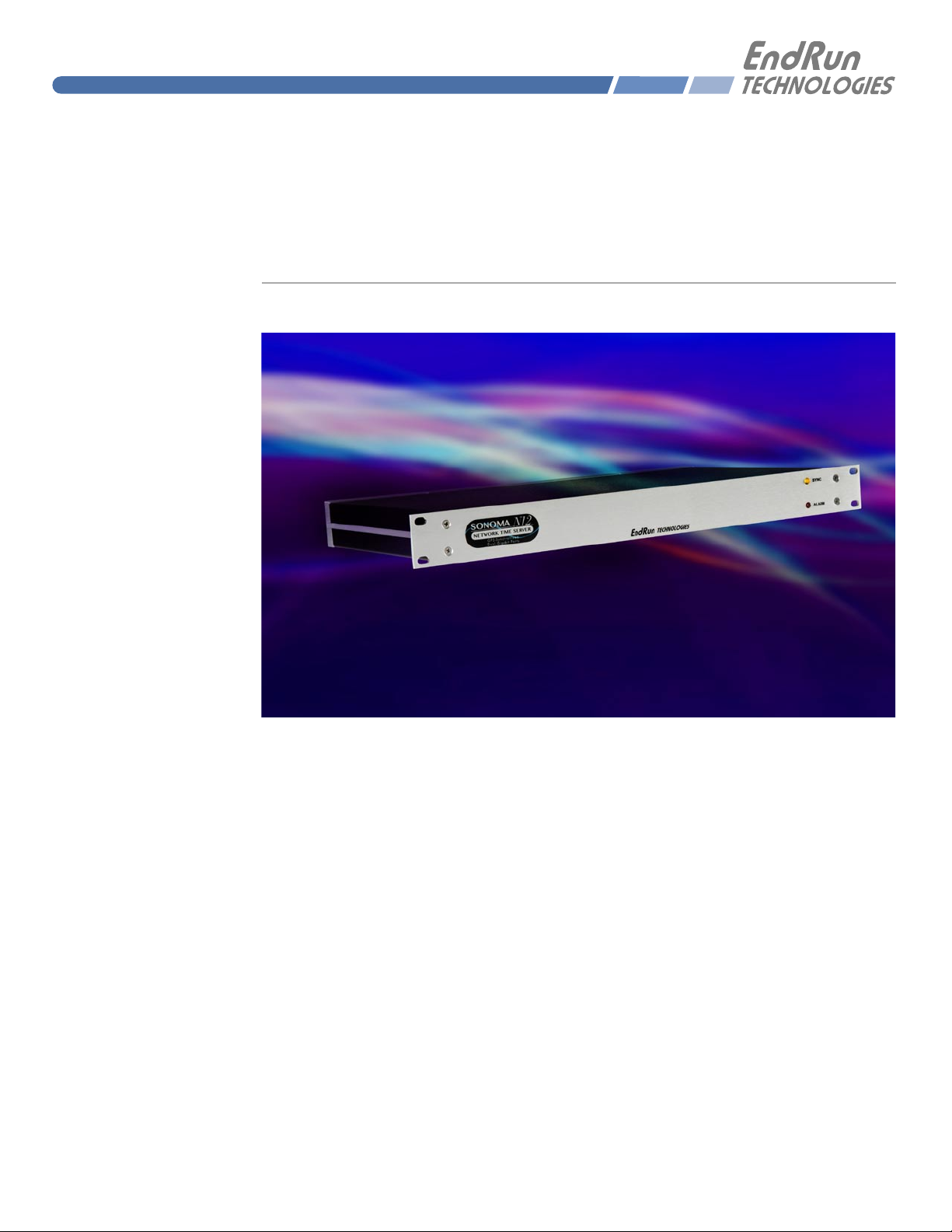
Sonoma N12
GPS-Synchronized
Network Time Server
User Manual
USM3029-0000-000 Revision 5
June 2017
Page 2

Page 3

Sonoma N12
GPS
Network Time Server User Manual
Preface
Thank you for purchasing the Sonoma Network Time Server. Our goal in developing this product is
to bring precise, Coordinated Universal Time (UTC) into your network quickly, easily and reliably.
Your new Time Server is fabricated using the highest quality materials and manufacturing processes
available today, and will give you years of troublefree service.
About EndRun Technologies
EndRun Technologies has been dedicated to the development and renement of the technologies
required to fulll the demanding needs of the time and frequency community since 1998.
The instruments produced by EndRun Technologies have been selected as the timing reference for
such rigorous applications as computer synchronization, research institutions, aerospace, network
quality-of-service monitoring, satellite base stations, and calibration laboratories.
Trademark Acknowledgements
Linux, UNIX, and Windows are registered trademarks of the respective holders.
EndRun Contact Information
Address: EndRun Technologies
2270 Northpoint Parkway
Santa Rosa, CA 95407
U.S.A.
Phone: (707)573-8633
Fax: (707)573-8619
Sales: 1-877-749-3878 or (707)573-8633
[email protected]
Support: 1-877-749-3878 or (707)573-8633
[email protected]
Part No. USM3029-0000-000 Revision 5
June 2017
Copyright © EndRun Technologies 2013-2017
S o n o m a U s e r M a n u a l
Page 4

S o n o m a U s e r M a n u a l
About This Manual
This manual will guide you through simple installation and set up procedures.
Introduction – The Sonoma N12, how it works, where to use it, its main features.
Basic Installation – How to connect, congure and test your Sonoma with your network.
NTP Server and Client Set-Up – Two client sections; one for Unix-like platforms and one for Windows.
Network Protocols - Covers Security, SNMP, HTTP, IPv6 and PTP/IEEE-1588.
Console Port – Description of the console commands for use over the network and serial ports.
Options – Description of any optional features that your Sonoma might have.
If you detect any inaccuracies or omissions, please inform us. EndRun Technologies cannot be held
responsible for any technical or typographical errors and reserves the right to make changes to the
product and manuals without prior notice.
Warranty
This product, manufactured by EndRun Technologies, is warranted against defects in material and
workmanship for a period of three years from date of shipment, under normal use and service. During the warranty period, EndRun Technologies will repair or replace, at its option, products which
prove to be defective.
For warranty service or repair, this product must be returned to EndRun Technologies. Buyer shall
prepay shipping charges to send product to EndRun Technologies and EndRun Technologies shall
pay shipping charges to return product to Buyer. However, if returned product proves to be operating
normally (not defective) then Buyer shall pay for all shipping charges. If Buyer is located outside the
U.S.A. then Buyer shall pay all duties and taxes, if any.
Products not manufactured by EndRun Technologies but included as an integral part of a system (e.g.
peripherals, options) are warranted for ninety days, or longer as provided by the original equipment
manufacturer, from date of shipment.
Extended Warranty
EndRun products are very reliable and rarely need to be returned to the factory for service. After the
initial warranty period it is most cost-effective for the customer to repair the unit on an “as needed basis”, rather than pay for an extended warranty or the annually recurring fees of a service contract..
Limitation of Warranty
The foregoing express warranty shall not apply to defects resulting from improper or inadequate
maintenance by Buyer or User, Buyer-supplied software or interfacing, unauthorized modication or
misuse, operation outside of the environmental specications for the product, or improper site preparation or maintenance.
S o n o m a U s e r M a n u a l
Page 5

TO THE EXTENT PERMITTED BY LAW, THIS WARRANTY AND REMEDIES SET FORTH
ABOVE ARE EXCLUSIVE AND IN LIEU OF ALL OTHER WARRANTIES, REMEDIES AND
CONDITIONS WHETHER ORAL OR WRITTEN, STATUTORY, EXPRESS, OR IMPLIED. AS
PERMITTED BY APPLICABLE LAW, ENDRUN SPECIFICALLY DISCLAIMS THE IMPLIED
WARRANTIES OF MERCHANTABILITY OR FITNESS FOR A PARTICULAR PURPOSE.
Warranty Repair
If you believe your equipment is in need of repair, call EndRun Technologies and ask for a customer
service agent. It is important to contact us rst as many problems may be resolved with a phone call.
Please have the serial number of the unit and the nature of the problem available before you call. If
it is determined that your equipment will require service, we will issue an RMA number. You will be
asked for contact information, including your name, address, phone number and e-mail address.
Ship the unit prepaid in the original container or a container of sufcient strength and protection to
EndRun Technologies. EndRun will not be responsible for damage incurred during shipment to us.
Be sure the RMA number is clearly identied on the shipping container. Our policy is to repair the
unit within 5 business days. If it is necessary to order parts or if other circumstances arise that require
more than 5 days, an EndRun service technician will contact you.
Loaner units are not included as part of the standard warranty.
Repair After Warranty Expiration
If the warranty period has expired, we offer repair services for equipment you have purchased from
EndRun. Call and ask for a customer service agent. It is important to contact us rst as many problems may be resolved with a phone call. Please have the serial number of the unit and the nature of
the problem available before you call. If it is determined that the equipment has failed and you want
EndRun to perform the repairs, we will issue you an RMA number.
Ship the unit prepaid in the original container or a container of sufcient strength and protection to
EndRun Technologies. EndRun will not be responsible for damage incurred during shipment to us.
Customer is responsible for shipping costs to and from EndRun Technologies. Be sure the RMA
number is clearly identied on the shipping container. After the equipment has been received we will
evaluate the nature of the problem and contact you with the cost to repair (parts and labor) and an
estimate of the time necessary to complete the work.
Limitation of Liability
The remedies provided herein are Buyer’s sole and exclusive remedies. EndRun Technologies shall
not be liable for any direct, indirect, special, incidental or consequential damages, whether based on
contract, tort or any other legal theory.
S o n o m a U s e r M a n u a l
Page 6

S o n o m a U s e r M a n u a l
Table of Contents
Preface . . . . . . . . . . . . . . . . . . . . . . . . . . . . . . . . . . . . . . . . . . . . . . . . . . . . . . . . . . . . . . . . . .i
About EndRun Technologies . . . . . . . . . . . . . . . . . . . . . . . . . . . . . . . . . . . . . . . . . . . . . . . . . . . . i
Trademark Acknowledgements . . . . . . . . . . . . . . . . . . . . . . . . . . . . . . . . . . . . . . . . . . . . . . . . . .i
EndRun Contact Information . . . . . . . . . . . . . . . . . . . . . . . . . . . . . . . . . . . . . . . . . . . . . . . . . . .i
About This Manual . . . . . . . . . . . . . . . . . . . . . . . . . . . . . . . . . . . . . . . . . . . . . . . . . . . . . . . . . ii
Warranty . . . . . . . . . . . . . . . . . . . . . . . . . . . . . . . . . . . . . . . . . . . . . . . . . . . . . . . . . . . . . . . . ii
Extended Warranty . . . . . . . . . . . . . . . . . . . . . . . . . . . . . . . . . . . . . . . . . . . . . . . . . . . . . . . . . ii
Limitation of Warranty . . . . . . . . . . . . . . . . . . . . . . . . . . . . . . . . . . . . . . . . . . . . . . . . . . . . . . ii
Warranty Repair . . . . . . . . . . . . . . . . . . . . . . . . . . . . . . . . . . . . . . . . . . . . . . . . . . . . . . . . . . iii
Repair After Warranty Expiration . . . . . . . . . . . . . . . . . . . . . . . . . . . . . . . . . . . . . . . . . . . . . . . iii
Limitation of Liability . . . . . . . . . . . . . . . . . . . . . . . . . . . . . . . . . . . . . . . . . . . . . . . . . . . . . . . iii
Chapter One - Introduction . . . . . . . . . . . . . . . . . . . . . . . . . . . . . . . . . . . . . . . . . . . . . . . 1
What It Is . . . . . . . . . . . . . . . . . . . . . . . . . . . . . . . . . . . . . . . . . . . . . . . . . . . . . . . . . . . . . . . 1
GPS Timing-How It Works . . . . . . . . . . . . . . . . . . . . . . . . . . . . . . . . . . . . . . . . . . . . . . . . . . . . 1
GPS Receivers . . . . . . . . . . . . . . . . . . . . . . . . . . . . . . . . . . . . . . . . . . . . . . . . . . . . . . . . . . . . 2
Time Synchronization Components . . . . . . . . . . . . . . . . . . . . . . . . . . . . . . . . . . . . . . . . . . . . . . 2
Where to Use It . . . . . . . . . . . . . . . . . . . . . . . . . . . . . . . . . . . . . . . . . . . . . . . . . . . . . . . . . . . 3
Client/Slave Software . . . . . . . . . . . . . . . . . . . . . . . . . . . . . . . . . . . . . . . . . . . . . . . . . . . . . . . 3
Chapter Two - Basic Installation . . . . . . . . . . . . . . . . . . . . . . . . . . . . . . . . . . . . . . . . . . . 5
Checking and Identifying the Hardware . . . . . . . . . . . . . . . . . . . . . . . . . . . . . . . . . . . . . . . . . . . 5
Sonoma Physical Description . . . . . . . . . . . . . . . . . . . . . . . . . . . . . . . . . . . . . . . . . . . . . . . . . . 6
Performing a Site Survey . . . . . . . . . . . . . . . . . . . . . . . . . . . . . . . . . . . . . . . . . . . . . . . . . . . . . 7
Installing the Sonoma . . . . . . . . . . . . . . . . . . . . . . . . . . . . . . . . . . . . . . . . . . . . . . . . . . . . . . . 8
Connecting the Optional DC Power . . . . . . . . . . . . . . . . . . . . . . . . . . . . . . . . . . . . . . . . . . . . . . . . 8
Connecting and Configuring Ethernet . . . . . . . . . . . . . . . . . . . . . . . . . . . . . . . . . . . . . . . . . . . . . . . 8
Configuring Ethernet with the Serial Port . . . . . . . . . . . . . . . . . . . . . . . . . . . . . . . . . . . . . . . . . . . . 9
Connect the RS-232 Serial I/O Port . . . . . . . . . . . . . . . . . . . . . . . . . . . . . . . . . . . . . . . . . . . . . . . . 9
Test the Serial Port . . . . . . . . . . . . . . . . . . . . . . . . . . . . . . . . . . . . . . . . . . . . . . . . . . . . . . . . 9
Using netconfig to Set Up Your IP . . . . . . . . . . . . . . . . . . . . . . . . . . . . . . . . . . . . . . . . . . . . . . . 11
S o n o m a U s e r M a n u a l
Page 7

Verify Network Configuration . . . . . . . . . . . . . . . . . . . . . . . . . . . . . . . . . . . . . . . . . . . . . . . . . . 12
Check Network Operation . . . . . . . . . . . . . . . . . . . . . . . . . . . . . . . . . . . . . . . . . . . . . . . . . . . . 14
Using Telnet . . . . . . . . . . . . . . . . . . . . . . . . . . . . . . . . . . . . . . . . . . . . . . . . . . . . . . . . . . . . 14
Using SSH . . . . . . . . . . . . . . . . . . . . . . . . . . . . . . . . . . . . . . . . . . . . . . . . . . . . . . . . . . . . . 15
Using HTTPS . . . . . . . . . . . . . . . . . . . . . . . . . . . . . . . . . . . . . . . . . . . . . . . . . . . . . . . . . . . 15
Chapter Three - Network Time Protocol (NTP) . . . . . . . . . . . . . . . . . . . . . . . . . . . . . 17
Configuring the NTP Server . . . . . . . . . . . . . . . . . . . . . . . . . . . . . . . . . . . . . . . . . . . . . . . . . . 17
Configuring the Sonoma as a Stratum 1 Server . . . . . . . . . . . . . . . . . . . . . . . . . . . . . . . . . . . . . . . . 17
Configuring NTP Using the Network Interface or Serial Port . . . . . . . . . . . . . . . . . . . . . . . . . . . . . . . . . . 17
Configuring the Sonoma as a Stratum 2 Server . . . . . . . . . . . . . . . . . . . . . . . . . . . . . . . . . . . . . . . . 20
Edit ntp.conf File . . . . . . . . . . . . . . . . . . . . . . . . . . . . . . . . . . . . . . . . . . . . . . . . . . . . . . . . 20
Mask Alarm . . . . . . . . . . . . . . . . . . . . . . . . . . . . . . . . . . . . . . . . . . . . . . . . . . . . . . . . . . 20
Setting Up NTP Clients on Unix-like Platforms . . . . . . . . . . . . . . . . . . . . . . . . . . . . . . . . . . . . . 21
Unix-like Platforms: Basic NTP Client Setup . . . . . . . . . . . . . . . . . . . . . . . . . . . . . . . . . . . . . . . . . . 21
Configure NTP . . . . . . . . . . . . . . . . . . . . . . . . . . . . . . . . . . . . . . . . . . . . . . . . . . . . . . . . . 21
Unix-like Platforms: MD5 Authenticated NTP Client Setup . . . . . . . . . . . . . . . . . . . . . . . . . . . . . . . . . . 22
Create the ntp.keys File . . . . . . . . . . . . . . . . . . . . . . . . . . . . . . . . . . . . . . . . . . . . . . . . . . . . 22
Configure NTP . . . . . . . . . . . . . . . . . . . . . . . . . . . . . . . . . . . . . . . . . . . . . . . . . . . . . . . . . 23
Unix-like Platforms: Broadcast/Multicast NTP Client Setup . . . . . . . . . . . . . . . . . . . . . . . . . . . . . . . . . . 23
Configure NTP Client for Broadcast . . . . . . . . . . . . . . . . . . . . . . . . . . . . . . . . . . . . . . . . . . . . . . . 24
Configure NTP Client for Multicast . . . . . . . . . . . . . . . . . . . . . . . . . . . . . . . . . . . . . . . . . . . . . . . 24
Test Broadcast/Multicast . . . . . . . . . . . . . . . . . . . . . . . . . . . . . . . . . . . . . . . . . . . . . . . . . . . . 25
Setting Up NTP Clients on Windows . . . . . . . . . . . . . . . . . . . . . . . . . . . . . . . . . . . . . . . . . . . . 26
Windows: Basic NTP Client Setup . . . . . . . . . . . . . . . . . . . . . . . . . . . . . . . . . . . . . . . . . . . . . . . . 26
Windows: w32time . . . . . . . . . . . . . . . . . . . . . . . . . . . . . . . . . . . . . . . . . . . . . . . . . . . . . . . 26
Windows: ntpd . . . . . . . . . . . . . . . . . . . . . . . . . . . . . . . . . . . . . . . . . . . . . . . . . . . . . . . . . 26
Windows: MD5 Authenticated NTP Client Setup . . . . . . . . . . . . . . . . . . . . . . . . . . . . . . . . . . . . . . . . 27
Create the ntp.keys File . . . . . . . . . . . . . . . . . . . . . . . . . . . . . . . . . . . . . . . . . . . . . . . . . . . . 28
Configure NTP . . . . . . . . . . . . . . . . . . . . . . . . . . . . . . . . . . . . . . . . . . . . . . . . . . . . . . . . . 28
Windows: Broadcast/Multicast NTP Client Setup . . . . . . . . . . . . . . . . . . . . . . . . . . . . . . . . . . . . . . . . 29
Configure NTP Client for Broadcast . . . . . . . . . . . . . . . . . . . . . . . . . . . . . . . . . . . . . . . . . . . . . . . 29
Configure NTP Client for Multicast . . . . . . . . . . . . . . . . . . . . . . . . . . . . . . . . . . . . . . . . . . . . . . . 30
Test Broadcast/Multicast . . . . . . . . . . . . . . . . . . . . . . . . . . . . . . . . . . . . . . . . . . . . . . . . . . . . 30
S o n o m a U s e r M a n u a l
Page 8

S o n o m a U s e r M a n u a l
Chapter Four - Precision Time Protocol (PTP/IEEE-1588) . . . . . . . . . . . . . . . . . . . 33
Option . . . . . . . . . . . . . . . . . . . . . . . . . . . . . . . . . . . . . . . . . . . . . . . . . . . . . . . . . . . . . . . . 33
About PTP . . . . . . . . . . . . . . . . . . . . . . . . . . . . . . . . . . . . . . . . . . . . . . . . . . . . . . . . . . . . . . 33
Two Gigabit Ports . . . . . . . . . . . . . . . . . . . . . . . . . . . . . . . . . . . . . . . . . . . . . . . . . . . . . . . . . 34
PTP Configuration and Status . . . . . . . . . . . . . . . . . . . . . . . . . . . . . . . . . . . . . . . . . . . . . . . . . 34
PTP Configuration Using the Network or Serial Port . . . . . . . . . . . . . . . . . . . . . . . . . . . . . . . . . . . . . 34
PTP Status Using the Network or Serial Port . . . . . . . . . . . . . . . . . . . . . . . . . . . . . . . . . . . . . . . . . 36
PTP Operation . . . . . . . . . . . . . . . . . . . . . . . . . . . . . . . . . . . . . . . . . . . . . . . . . . . . . . . . . . . 37
About the PTP Second and UTC Time . . . . . . . . . . . . . . . . . . . . . . . . . . . . . . . . . . . . . . . . . . . . 39
PTP Second . . . . . . . . . . . . . . . . . . . . . . . . . . . . . . . . . . . . . . . . . . . . . . . . . . . . . . . . . . . . 39
UTC Time . . . . . . . . . . . . . . . . . . . . . . . . . . . . . . . . . . . . . . . . . . . . . . . . . . . . . . . . . . . . . 39
Multiport PTP . . . . . . . . . . . . . . . . . . . . . . . . . . . . . . . . . . . . . . . . . . . . . . . . . . . . . . . . . . . 39
Disable the PTP Protocol . . . . . . . . . . . . . . . . . . . . . . . . . . . . . . . . . . . . . . . . . . . . . . . . . . . . 40
Re-Enable PTP . . . . . . . . . . . . . . . . . . . . . . . . . . . . . . . . . . . . . . . . . . . . . . . . . . . . . . . . . . 40
Chapter Five - Security . . . . . . . . . . . . . . . . . . . . . . . . . . . . . . . . . . . . . . . . . . . . . . . . . . 41
Linux Operating System . . . . . . . . . . . . . . . . . . . . . . . . . . . . . . . . . . . . . . . . . . . . . . . . . . . . 41
Restrict Access . . . . . . . . . . . . . . . . . . . . . . . . . . . . . . . . . . . . . . . . . . . . . . . . . . . . . . . . . . . 42
Restrict Access - Telnet, SSH and SNMP . . . . . . . . . . . . . . . . . . . . . . . . . . . . . . . . . . . . . . . . . . . . . 42
Restrict Access - HTTPS . . . . . . . . . . . . . . . . . . . . . . . . . . . . . . . . . . . . . . . . . . . . . . . . . . . . . . 43
Restrict Query Access - NTP . . . . . . . . . . . . . . . . . . . . . . . . . . . . . . . . . . . . . . . . . . . . . . . . . . . 44
Disable Protocols . . . . . . . . . . . . . . . . . . . . . . . . . . . . . . . . . . . . . . . . . . . . . . . . . . . . . . . . . 45
Disable Telnet, Time and Daytime . . . . . . . . . . . . . . . . . . . . . . . . . . . . . . . . . . . . . . . . . . . . . . . 45
Disable SNMP, SSH and HTTPS . . . . . . . . . . . . . . . . . . . . . . . . . . . . . . . . . . . . . . . . . . . . . . . . . 45
Re-Enable SNMP, SSH and HTTPS . . . . . . . . . . . . . . . . . . . . . . . . . . . . . . . . . . . . . . . . . . . . . . . 46
Is the Protocol Disabled? . . . . . . . . . . . . . . . . . . . . . . . . . . . . . . . . . . . . . . . . . . . . . . . . . . . . . 46
OpenSSH . . . . . . . . . . . . . . . . . . . . . . . . . . . . . . . . . . . . . . . . . . . . . . . . . . . . . . . . . . . . . . 46
Configure Keys . . . . . . . . . . . . . . . . . . . . . . . . . . . . . . . . . . . . . . . . . . . . . . . . . . . . . . . . . . 47
HTTPS . . . . . . . . . . . . . . . . . . . . . . . . . . . . . . . . . . . . . . . . . . . . . . . . . . . . . . . . . . . . . . . . 47
Configure Certificate and Key . . . . . . . . . . . . . . . . . . . . . . . . . . . . . . . . . . . . . . . . . . . . . . . . . . 48
NTP . . . . . . . . . . . . . . . . . . . . . . . . . . . . . . . . . . . . . . . . . . . . . . . . . . . . . . . . . . . . . . . . . . 48
Network Security Vulnerabilities . . . . . . . . . . . . . . . . . . . . . . . . . . . . . . . . . . . . . . . . . . . . . . . 48
S o n o m a U s e r M a n u a l
Page 9

Chapter Six - Simple Network Management Protocol (SNMP) . . . . . . . . . . . . . . 49
SNMPv3 Security . . . . . . . . . . . . . . . . . . . . . . . . . . . . . . . . . . . . . . . . . . . . . . . . . . . . . . . . . 49
Enterprise Management Information Base (MIB) . . . . . . . . . . . . . . . . . . . . . . . . . . . . . . . . . . . . 50
Invocation of the SNMP daemon . . . . . . . . . . . . . . . . . . . . . . . . . . . . . . . . . . . . . . . . . . . . . . . 50
Quick Start Configuration -- SNMPv1/v2c . . . . . . . . . . . . . . . . . . . . . . . . . . . . . . . . . . . . . . . . . 50
Change Default Community Strings (Passwords) . . . . . . . . . . . . . . . . . . . . . . . . . . . . . . . . . . . . . . . 51
Configuring SNMPv1 Trap Generation . . . . . . . . . . . . . . . . . . . . . . . . . . . . . . . . . . . . . . . . . . . 51
Configuring SNMPv2c Notifications and Informs . . . . . . . . . . . . . . . . . . . . . . . . . . . . . . . . . . . . 51
Configuration of SNMPv3 . . . . . . . . . . . . . . . . . . . . . . . . . . . . . . . . . . . . . . . . . . . . . . . . . . . 52
Disable or Restrict Access . . . . . . . . . . . . . . . . . . . . . . . . . . . . . . . . . . . . . . . . . . . . . . . . . . . . 53
Chapter Seven - Hyper Text Transport Protocol Secure (HTTPS) . . . . . . . . . . . . 55
HTTPS Interface Description . . . . . . . . . . . . . . . . . . . . . . . . . . . . . . . . . . . . . . . . . . . . . . . . . . 56
Navigation . . . . . . . . . . . . . . . . . . . . . . . . . . . . . . . . . . . . . . . . . . . . . . . . . . . . . . . . . . . . 57
Page Descriptions . . . . . . . . . . . . . . . . . . . . . . . . . . . . . . . . . . . . . . . . . . . . . . . . . . . . . . . . . 58
Home: Overall Status Page . . . . . . . . . . . . . . . . . . . . . . . . . . . . . . . . . . . . . . . . . . . . . . . . . . . 58
Home: User Manual . . . . . . . . . . . . . . . . . . . . . . . . . . . . . . . . . . . . . . . . . . . . . . . . . . . . . . 58
Home: Logout . . . . . . . . . . . . . . . . . . . . . . . . . . . . . . . . . . . . . . . . . . . . . . . . . . . . . . . . . 58
Plots Page . . . . . . . . . . . . . . . . . . . . . . . . . . . . . . . . . . . . . . . . . . . . . . . . . . . . . . . . . . . . . 59
Receiver: Receiver Page . . . . . . . . . . . . . . . . . . . . . . . . . . . . . . . . . . . . . . . . . . . . . . . . . . . . . 60
Receiver: Oscillator Page . . . . . . . . . . . . . . . . . . . . . . . . . . . . . . . . . . . . . . . . . . . . . . . . . . . . 61
Clock Page . . . . . . . . . . . . . . . . . . . . . . . . . . . . . . . . . . . . . . . . . . . . . . . . . . . . . . . . . . . . 62
I/O Page . . . . . . . . . . . . . . . . . . . . . . . . . . . . . . . . . . . . . . . . . . . . . . . . . . . . . . . . . . . . . . 62
Faults: System Faults Page . . . . . . . . . . . . . . . . . . . . . . . . . . . . . . . . . . . . . . . . . . . . . . . . . . . 62
Faults: Fault Mask Page . . . . . . . . . . . . . . . . . . . . . . . . . . . . . . . . . . . . . . . . . . . . . . . . . . . . 63
Network: IPv4 Page . . . . . . . . . . . . . . . . . . . . . . . . . . . . . . . . . . . . . . . . . . . . . . . . . . . . . . . 63
Network: IPv6 Page . . . . . . . . . . . . . . . . . . . . . . . . . . . . . . . . . . . . . . . . . . . . . . . . . . . . . . 63
Network: DNS Page . . . . . . . . . . . . . . . . . . . . . . . . . . . . . . . . . . . . . . . . . . . . . . . . . . . . . . 63
Network: MAC Address Page . . . . . . . . . . . . . . . . . . . . . . . . . . . . . . . . . . . . . . . . . . . . . . . . . . 63
NTP Page . . . . . . . . . . . . . . . . . . . . . . . . . . . . . . . . . . . . . . . . . . . . . . . . . . . . . . . . . . . . . 64
PTP: Status and Configuration Pages . . . . . . . . . . . . . . . . . . . . . . . . . . . . . . . . . . . . . . . . . . . . . . 64
Firmware: Firmware Status Page . . . . . . . . . . . . . . . . . . . . . . . . . . . . . . . . . . . . . . . . . . . . . . . . 64
Firmware: Linux RFS Upgrade Page . . . . . . . . . . . . . . . . . . . . . . . . . . . . . . . . . . . . . . . . . . . . . . 65
Firmware: Linux Kernel Upgrade . . . . . . . . . . . . . . . . . . . . . . . . . . . . . . . . . . . . . . . . . . . . . . . 65
S o n o m a U s e r M a n u a l
Page 10

S o n o m a U s e r M a n u a l
Firmware: GPS Subsystem Upgrade Page . . . . . . . . . . . . . . . . . . . . . . . . . . . . . . . . . . . . . . . . . . . 65
Firmware: Reboot Page . . . . . . . . . . . . . . . . . . . . . . . . . . . . . . . . . . . . . . . . . . . . . . . . . . . . 65
Disable or Restrict Access . . . . . . . . . . . . . . . . . . . . . . . . . . . . . . . . . . . . . . . . . . . . . . . . . . . . 65
Chapter Eight - IPv6 . . . . . . . . . . . . . . . . . . . . . . . . . . . . . . . . . . . . . . . . . . . . . . . . . . . . 67
IPv6 Capabilities . . . . . . . . . . . . . . . . . . . . . . . . . . . . . . . . . . . . . . . . . . . . . . . . . . . . . . . . . 67
OpenSSH . . . . . . . . . . . . . . . . . . . . . . . . . . . . . . . . . . . . . . . . . . . . . . . . . . . . . . . . . . . . . 67
Apache HTTP . . . . . . . . . . . . . . . . . . . . . . . . . . . . . . . . . . . . . . . . . . . . . . . . . . . . . . . . . . . 67
Net-SNMP . . . . . . . . . . . . . . . . . . . . . . . . . . . . . . . . . . . . . . . . . . . . . . . . . . . . . . . . . . . . . 67
NTP . . . . . . . . . . . . . . . . . . . . . . . . . . . . . . . . . . . . . . . . . . . . . . . . . . . . . . . . . . . . . . . . 68
IPv4-Only Protocols . . . . . . . . . . . . . . . . . . . . . . . . . . . . . . . . . . . . . . . . . . . . . . . . . . . . . . . 68
Chapter Nine - Console Port Control and Status . . . . . . . . . . . . . . . . . . . . . . . . . . . 69
Console Ports . . . . . . . . . . . . . . . . . . . . . . . . . . . . . . . . . . . . . . . . . . . . . . . . . . . . . . . . . . . . 69
General Linux Operation . . . . . . . . . . . . . . . . . . . . . . . . . . . . . . . . . . . . . . . . . . . . . . . . . . . . 69
Available User Commands . . . . . . . . . . . . . . . . . . . . . . . . . . . . . . . . . . . . . . . . . . . . . . . . . . . 70
Detailed Command Descriptions . . . . . . . . . . . . . . . . . . . . . . . . . . . . . . . . . . . . . . . . . . . . . . . 73
accessconfig . . . . . . . . . . . . . . . . . . . . . . . . . . . . . . . . . . . . . . . . . . . . . . . . . . . . . . . . . . . . 73
antfltmask . . . . . . . . . . . . . . . . . . . . . . . . . . . . . . . . . . . . . . . . . . . . . . . . . . . . . . . . . . . . . 74
caldelay . . . . . . . . . . . . . . . . . . . . . . . . . . . . . . . . . . . . . . . . . . . . . . . . . . . . . . . . . . . . . . 74
cpuio (Optional) . . . . . . . . . . . . . . . . . . . . . . . . . . . . . . . . . . . . . . . . . . . . . . . . . . . . . . . . . 74
cpuioconfig (Optional) . . . . . . . . . . . . . . . . . . . . . . . . . . . . . . . . . . . . . . . . . . . . . . . . . . . . . . 74
cpustat . . . . . . . . . . . . . . . . . . . . . . . . . . . . . . . . . . . . . . . . . . . . . . . . . . . . . . . . . . . . . . . 74
faultstat . . . . . . . . . . . . . . . . . . . . . . . . . . . . . . . . . . . . . . . . . . . . . . . . . . . . . . . . . . . . . . 75
get_sw_opts . . . . . . . . . . . . . . . . . . . . . . . . . . . . . . . . . . . . . . . . . . . . . . . . . . . . . . . . . . . 75
gpsdynmode . . . . . . . . . . . . . . . . . . . . . . . . . . . . . . . . . . . . . . . . . . . . . . . . . . . . . . . . . . . 75
gpslastfix . . . . . . . . . . . . . . . . . . . . . . . . . . . . . . . . . . . . . . . . . . . . . . . . . . . . . . . . . . . . . 75
gpsrefpos . . . . . . . . . . . . . . . . . . . . . . . . . . . . . . . . . . . . . . . . . . . . . . . . . . . . . . . . . . . . . 76
gpsstat . . . . . . . . . . . . . . . . . . . . . . . . . . . . . . . . . . . . . . . . . . . . . . . . . . . . . . . . . . . . . . . 76
gpstrkstat . . . . . . . . . . . . . . . . . . . . . . . . . . . . . . . . . . . . . . . . . . . . . . . . . . . . . . . . . . . . . 78
gpsutcinfo . . . . . . . . . . . . . . . . . . . . . . . . . . . . . . . . . . . . . . . . . . . . . . . . . . . . . . . . . . . . . 78
gpsversion . . . . . . . . . . . . . . . . . . . . . . . . . . . . . . . . . . . . . . . . . . . . . . . . . . . . . . . . . . . . . 79
help . . . . . . . . . . . . . . . . . . . . . . . . . . . . . . . . . . . . . . . . . . . . . . . . . . . . . . . . . . . . . . . . 79
inetdconfig . . . . . . . . . . . . . . . . . . . . . . . . . . . . . . . . . . . . . . . . . . . . . . . . . . . . . . . . . . . . 79
S o n o m a U s e r M a n u a l
Page 11

kernelversion . . . . . . . . . . . . . . . . . . . . . . . . . . . . . . . . . . . . . . . . . . . . . . . . . . . . . . . . . . . 79
netconfig . . . . . . . . . . . . . . . . . . . . . . . . . . . . . . . . . . . . . . . . . . . . . . . . . . . . . . . . . . . . . 79
ntpconfig . . . . . . . . . . . . . . . . . . . . . . . . . . . . . . . . . . . . . . . . . . . . . . . . . . . . . . . . . . . . . 80
ntpstat . . . . . . . . . . . . . . . . . . . . . . . . . . . . . . . . . . . . . . . . . . . . . . . . . . . . . . . . . . . . . . . 80
oscctrlstat . . . . . . . . . . . . . . . . . . . . . . . . . . . . . . . . . . . . . . . . . . . . . . . . . . . . . . . . . . . . . 81
passwd . . . . . . . . . . . . . . . . . . . . . . . . . . . . . . . . . . . . . . . . . . . . . . . . . . . . . . . . . . . . . . . 82
ptpconfig0 and ptpconfig1 (Optional) . . . . . . . . . . . . . . . . . . . . . . . . . . . . . . . . . . . . . . . . . . . . . 82
ptpstat0 and ptpstat1 (Optional) . . . . . . . . . . . . . . . . . . . . . . . . . . . . . . . . . . . . . . . . . . . . . . . . 82
pwrfltmask (Optional) . . . . . . . . . . . . . . . . . . . . . . . . . . . . . . . . . . . . . . . . . . . . . . . . . . . . . . 82
rcvrserialnumber . . . . . . . . . . . . . . . . . . . . . . . . . . . . . . . . . . . . . . . . . . . . . . . . . . . . . . . . . 82
rcvrstat . . . . . . . . . . . . . . . . . . . . . . . . . . . . . . . . . . . . . . . . . . . . . . . . . . . . . . . . . . . . . . 83
rcvrversion . . . . . . . . . . . . . . . . . . . . . . . . . . . . . . . . . . . . . . . . . . . . . . . . . . . . . . . . . . . . 83
resetlastgpswn . . . . . . . . . . . . . . . . . . . . . . . . . . . . . . . . . . . . . . . . . . . . . . . . . . . . . . . . . . 83
resetleaphistory . . . . . . . . . . . . . . . . . . . . . . . . . . . . . . . . . . . . . . . . . . . . . . . . . . . . . . . . . . 83
serialnumber . . . . . . . . . . . . . . . . . . . . . . . . . . . . . . . . . . . . . . . . . . . . . . . . . . . . . . . . . . . 83
setantfltmask . . . . . . . . . . . . . . . . . . . . . . . . . . . . . . . . . . . . . . . . . . . . . . . . . . . . . . . . . . . 83
setcaldelay . . . . . . . . . . . . . . . . . . . . . . . . . . . . . . . . . . . . . . . . . . . . . . . . . . . . . . . . . . . . 84
setgpsdynmode . . . . . . . . . . . . . . . . . . . . . . . . . . . . . . . . . . . . . . . . . . . . . . . . . . . . . . . . . . 84
setgpsrefpos . . . . . . . . . . . . . . . . . . . . . . . . . . . . . . . . . . . . . . . . . . . . . . . . . . . . . . . . . . . . 84
setsigfltmask . . . . . . . . . . . . . . . . . . . . . . . . . . . . . . . . . . . . . . . . . . . . . . . . . . . . . . . . . . . 85
sigfltmask . . . . . . . . . . . . . . . . . . . . . . . . . . . . . . . . . . . . . . . . . . . . . . . . . . . . . . . . . . . . . 85
subsysreset . . . . . . . . . . . . . . . . . . . . . . . . . . . . . . . . . . . . . . . . . . . . . . . . . . . . . . . . . . . . 85
syskernel . . . . . . . . . . . . . . . . . . . . . . . . . . . . . . . . . . . . . . . . . . . . . . . . . . . . . . . . . . . . . 85
sysosctype . . . . . . . . . . . . . . . . . . . . . . . . . . . . . . . . . . . . . . . . . . . . . . . . . . . . . . . . . . . . . 86
sysrootfs . . . . . . . . . . . . . . . . . . . . . . . . . . . . . . . . . . . . . . . . . . . . . . . . . . . . . . . . . . . . . . 86
sysstat . . . . . . . . . . . . . . . . . . . . . . . . . . . . . . . . . . . . . . . . . . . . . . . . . . . . . . . . . . . . . . . 86
systemio (Optional) . . . . . . . . . . . . . . . . . . . . . . . . . . . . . . . . . . . . . . . . . . . . . . . . . . . . . . . 87
systemioconfig (Optional) . . . . . . . . . . . . . . . . . . . . . . . . . . . . . . . . . . . . . . . . . . . . . . . . . . . . 87
systimemode . . . . . . . . . . . . . . . . . . . . . . . . . . . . . . . . . . . . . . . . . . . . . . . . . . . . . . . . . . . 87
systimemodeconfig . . . . . . . . . . . . . . . . . . . . . . . . . . . . . . . . . . . . . . . . . . . . . . . . . . . . . . . . 87
sysversion . . . . . . . . . . . . . . . . . . . . . . . . . . . . . . . . . . . . . . . . . . . . . . . . . . . . . . . . . . . . . 88
updaterootflag . . . . . . . . . . . . . . . . . . . . . . . . . . . . . . . . . . . . . . . . . . . . . . . . . . . . . . . . . . 88
updatekernelflag . . . . . . . . . . . . . . . . . . . . . . . . . . . . . . . . . . . . . . . . . . . . . . . . . . . . . . . . . 88
S o n o m a U s e r M a n u a l
Page 12

S o n o m a U s e r M a n u a l
upgradekernel . . . . . . . . . . . . . . . . . . . . . . . . . . . . . . . . . . . . . . . . . . . . . . . . . . . . . . . . . . 88
upgradercvr . . . . . . . . . . . . . . . . . . . . . . . . . . . . . . . . . . . . . . . . . . . . . . . . . . . . . . . . . . . . 89
upgradercvrfpga . . . . . . . . . . . . . . . . . . . . . . . . . . . . . . . . . . . . . . . . . . . . . . . . . . . . . . . . . 89
upgraderootfs . . . . . . . . . . . . . . . . . . . . . . . . . . . . . . . . . . . . . . . . . . . . . . . . . . . . . . . . . . . 89
upgradesubsys . . . . . . . . . . . . . . . . . . . . . . . . . . . . . . . . . . . . . . . . . . . . . . . . . . . . . . . . . . 89
wrt_sw_opt . . . . . . . . . . . . . . . . . . . . . . . . . . . . . . . . . . . . . . . . . . . . . . . . . . . . . . . . . . . . 90
Chapter Ten - Options . . . . . . . . . . . . . . . . . . . . . . . . . . . . . . . . . . . . . . . . . . . . . . . . . . . 91
Software Options . . . . . . . . . . . . . . . . . . . . . . . . . . . . . . . . . . . . . . . . . . . . . . . . . . . . . . . . . 91
wrt_sw_opt . . . . . . . . . . . . . . . . . . . . . . . . . . . . . . . . . . . . . . . . . . . . . . . . . . . . . . . . . . . . 91
get_sw_opts . . . . . . . . . . . . . . . . . . . . . . . . . . . . . . . . . . . . . . . . . . . . . . . . . . . . . . . . . . . 91
Software Option Bit Definitions . . . . . . . . . . . . . . . . . . . . . . . . . . . . . . . . . . . . . . . . . . . . . . . . . 92
CPU Module Options . . . . . . . . . . . . . . . . . . . . . . . . . . . . . . . . . . . . . . . . . . . . . . . . . . . . . . . 92
Programmable Pulse Output (PPO) . . . . . . . . . . . . . . . . . . . . . . . . . . . . . . . . . . . . . . . . . . . . . . 93
View and Change the PPO Configuration . . . . . . . . . . . . . . . . . . . . . . . . . . . . . . . . . . . . . . . . . . . . 93
1PPS Output . . . . . . . . . . . . . . . . . . . . . . . . . . . . . . . . . . . . . . . . . . . . . . . . . . . . . . . . . . . 93
View and Change the 1PPS Configuration . . . . . . . . . . . . . . . . . . . . . . . . . . . . . . . . . . . . . . . . . . . 93
Time Code Output . . . . . . . . . . . . . . . . . . . . . . . . . . . . . . . . . . . . . . . . . . . . . . . . . . . . . . . . 94
View and Change the Time Code Configuration . . . . . . . . . . . . . . . . . . . . . . . . . . . . . . . . . . . . . . . . 94
Fixed Rate Output (10 MPPS, etc.) . . . . . . . . . . . . . . . . . . . . . . . . . . . . . . . . . . . . . . . . . . . . . . . 94
View the Fixed Rate Output Connector . . . . . . . . . . . . . . . . . . . . . . . . . . . . . . . . . . . . . . . . . . . . . 94
Alarm Output . . . . . . . . . . . . . . . . . . . . . . . . . . . . . . . . . . . . . . . . . . . . . . . . . . . . . . . . . . . 95
View the Alarm Output Connector . . . . . . . . . . . . . . . . . . . . . . . . . . . . . . . . . . . . . . . . . . . . . . . 95
Direct Digital Synthesizer (DDS) . . . . . . . . . . . . . . . . . . . . . . . . . . . . . . . . . . . . . . . . . . . . . . . . 95
View and Change the DDS Configuration . . . . . . . . . . . . . . . . . . . . . . . . . . . . . . . . . . . . . . . . . . . . 95
Serial Time Output . . . . . . . . . . . . . . . . . . . . . . . . . . . . . . . . . . . . . . . . . . . . . . . . . . . . . . . . 96
View and Change the Serial Time Configuration . . . . . . . . . . . . . . . . . . . . . . . . . . . . . . . . . . . . . . . . 96
Sysplex Format . . . . . . . . . . . . . . . . . . . . . . . . . . . . . . . . . . . . . . . . . . . . . . . . . . . . . . . . . 96
Truetime Format . . . . . . . . . . . . . . . . . . . . . . . . . . . . . . . . . . . . . . . . . . . . . . . . . . . . . . . . 97
EndRun Format . . . . . . . . . . . . . . . . . . . . . . . . . . . . . . . . . . . . . . . . . . . . . . . . . . . . . . . . 97
EndRunX (Extended) Format . . . . . . . . . . . . . . . . . . . . . . . . . . . . . . . . . . . . . . . . . . . . . . . . . . 98
NENA Format . . . . . . . . . . . . . . . . . . . . . . . . . . . . . . . . . . . . . . . . . . . . . . . . . . . . . . . . . 98
NMEA Format . . . . . . . . . . . . . . . . . . . . . . . . . . . . . . . . . . . . . . . . . . . . . . . . . . . . . . . . 100
S o n o m a U s e r M a n u a l
Page 13

Power Supply Options . . . . . . . . . . . . . . . . . . . . . . . . . . . . . . . . . . . . . . . . . . . . . . . . . . . . . 103
DC Power Input . . . . . . . . . . . . . . . . . . . . . . . . . . . . . . . . . . . . . . . . . . . . . . . . . . . . . . . . . 103
Connecting the DC Power . . . . . . . . . . . . . . . . . . . . . . . . . . . . . . . . . . . . . . . . . . . . . . . . . . . 103
Dual-Redundant Power Supplies . . . . . . . . . . . . . . . . . . . . . . . . . . . . . . . . . . . . . . . . . . . . . . . 103
Masking Dual Power Supply Fault Alarms . . . . . . . . . . . . . . . . . . . . . . . . . . . . . . . . . . . . . . . . . . 104
Appendix A - Time Figure of Merit (TFOM) . . . . . . . . . . . . . . . . . . . . . . . . . . . . . . . 105
Appendix B - Upgrading the Firmware . . . . . . . . . . . . . . . . . . . . . . . . . . . . . . . . . . . 107
Upgrade via the HTTPS Interface . . . . . . . . . . . . . . . . . . . . . . . . . . . . . . . . . . . . . . . . . . . . . 107
Upgrade via the Console Port . . . . . . . . . . . . . . . . . . . . . . . . . . . . . . . . . . . . . . . . . . . . . . . . 109
Performing the Linux RFS Upgrade . . . . . . . . . . . . . . . . . . . . . . . . . . . . . . . . . . . . . . . . . . . . . . 109
Transfer File to Sonoma . . . . . . . . . . . . . . . . . . . . . . . . . . . . . . . . . . . . . . . . . . . . . . . . . . . 109
Recovering from a Failed RFS Upgrade . . . . . . . . . . . . . . . . . . . . . . . . . . . . . . . . . . . . . . . . . . . 111
Performing the Linux Kernel Upgrade . . . . . . . . . . . . . . . . . . . . . . . . . . . . . . . . . . . . . . . . . . . . 111
Transfer File to Sonoma . . . . . . . . . . . . . . . . . . . . . . . . . . . . . . . . . . . . . . . . . . . . . . . . . . . 111
Recovering from a Failed Kernel Upgrade . . . . . . . . . . . . . . . . . . . . . . . . . . . . . . . . . . . . . . . . . . 112
Performing the GPS Subsystem Upgrade . . . . . . . . . . . . . . . . . . . . . . . . . . . . . . . . . . . . . . . . . . . 113
Problems with the GPS Subsystem Upgrade . . . . . . . . . . . . . . . . . . . . . . . . . . . . . . . . . . . . . . . . . 114
Performing the GPS Receiver Upgrade . . . . . . . . . . . . . . . . . . . . . . . . . . . . . . . . . . . . . . . . . . . . 114
Problems with the GPS Receiver Upgrade . . . . . . . . . . . . . . . . . . . . . . . . . . . . . . . . . . . . . . . . . . 115
Performing the GPS Receiver FPGA Upgrade . . . . . . . . . . . . . . . . . . . . . . . . . . . . . . . . . . . . . . . . 115
Appendix C - Helpful Linux Information . . . . . . . . . . . . . . . . . . . . . . . . . . . . . . . . . . 117
Linux Users . . . . . . . . . . . . . . . . . . . . . . . . . . . . . . . . . . . . . . . . . . . . . . . . . . . . . . . . . . . . 117
Linux Commands . . . . . . . . . . . . . . . . . . . . . . . . . . . . . . . . . . . . . . . . . . . . . . . . . . . . . . . . 117
Detailed Information Is Available . . . . . . . . . . . . . . . . . . . . . . . . . . . . . . . . . . . . . . . . . . . . . . . 117
Change Password . . . . . . . . . . . . . . . . . . . . . . . . . . . . . . . . . . . . . . . . . . . . . . . . . . . . . . . . 118
List Active Processes . . . . . . . . . . . . . . . . . . . . . . . . . . . . . . . . . . . . . . . . . . . . . . . . . . . . . . 118
NTP Monitoring and Troubleshooting . . . . . . . . . . . . . . . . . . . . . . . . . . . . . . . . . . . . . . . . . . . . 118
Text Editors . . . . . . . . . . . . . . . . . . . . . . . . . . . . . . . . . . . . . . . . . . . . . . . . . . . . . . . . . . . . 119
Change Log-In Banners . . . . . . . . . . . . . . . . . . . . . . . . . . . . . . . . . . . . . . . . . . . . . . . . . . . . 119
Query and Change Ethernet Ports . . . . . . . . . . . . . . . . . . . . . . . . . . . . . . . . . . . . . . . . . . . . . 120
Redirect Syslog Files to Remote Host . . . . . . . . . . . . . . . . . . . . . . . . . . . . . . . . . . . . . . . . . . . 120
S o n o m a U s e r M a n u a l
Page 14

S o n o m a U s e r M a n u a l
Appendix D - Third-Party Software . . . . . . . . . . . . . . . . . . . . . . . . . . . . . . . . . . . . . 121
GNU General Public License . . . . . . . . . . . . . . . . . . . . . . . . . . . . . . . . . . . . . . . . . . . . . . . . . 121
NTP Software License . . . . . . . . . . . . . . . . . . . . . . . . . . . . . . . . . . . . . . . . . . . . . . . . . . . . . 126
Apache Software License . . . . . . . . . . . . . . . . . . . . . . . . . . . . . . . . . . . . . . . . . . . . . . . . . . . 126
PTP Software License . . . . . . . . . . . . . . . . . . . . . . . . . . . . . . . . . . . . . . . . . . . . . . . . . . . . . 128
Appendix E - Installing the GPS Antenna . . . . . . . . . . . . . . . . . . . . . . . . . . . . . . . . . 129
Antenna Location . . . . . . . . . . . . . . . . . . . . . . . . . . . . . . . . . . . . . . . . . . . . . . . . . . . . . . . . 129
GPS Antenna Kit . . . . . . . . . . . . . . . . . . . . . . . . . . . . . . . . . . . . . . . . . . . . . . . . . . . . . . . . 130
About Coax Cable . . . . . . . . . . . . . . . . . . . . . . . . . . . . . . . . . . . . . . . . . . . . . . . . . . . . . . . . 130
Long Cable Runs . . . . . . . . . . . . . . . . . . . . . . . . . . . . . . . . . . . . . . . . . . . . . . . . . . . . . . . . 131
Recommended Cable . . . . . . . . . . . . . . . . . . . . . . . . . . . . . . . . . . . . . . . . . . . . . . . . . . . . . . 131
Using GPS Preamplifiers . . . . . . . . . . . . . . . . . . . . . . . . . . . . . . . . . . . . . . . . . . . . . . . . . . . . 131
Using Three Preamplifiers . . . . . . . . . . . . . . . . . . . . . . . . . . . . . . . . . . . . . . . . . . . . . . . . . . 132
Other Accessories . . . . . . . . . . . . . . . . . . . . . . . . . . . . . . . . . . . . . . . . . . . . . . . . . . . . . . . . 132
Lightning Arrestor . . . . . . . . . . . . . . . . . . . . . . . . . . . . . . . . . . . . . . . . . . . . . . . . . . . . . . . 132
Signal Splitters . . . . . . . . . . . . . . . . . . . . . . . . . . . . . . . . . . . . . . . . . . . . . . . . . . . . . . . . . 132
Calibrate Your Receiver . . . . . . . . . . . . . . . . . . . . . . . . . . . . . . . . . . . . . . . . . . . . . . . . . . . . 133
Mounting On A Rooftop . . . . . . . . . . . . . . . . . . . . . . . . . . . . . . . . . . . . . . . . . . . . . . . . . . . . 134
Mounting Inside A Window . . . . . . . . . . . . . . . . . . . . . . . . . . . . . . . . . . . . . . . . . . . . . . . . . 135
Obtaining A Reference Position . . . . . . . . . . . . . . . . . . . . . . . . . . . . . . . . . . . . . . . . . . . . . . . 135
Using a Handheld GPS Receiver . . . . . . . . . . . . . . . . . . . . . . . . . . . . . . . . . . . . . . . . . . . . . . . 135
Using the Internet . . . . . . . . . . . . . . . . . . . . . . . . . . . . . . . . . . . . . . . . . . . . . . . . . . . . . . . 135
Using “Indirect GPS” . . . . . . . . . . . . . . . . . . . . . . . . . . . . . . . . . . . . . . . . . . . . . . . . . . . . . . 136
About WGS-84 Height . . . . . . . . . . . . . . . . . . . . . . . . . . . . . . . . . . . . . . . . . . . . . . . . . . . . . 136
Appendix F - Leap Seconds . . . . . . . . . . . . . . . . . . . . . . . . . . . . . . . . . . . . . . . . . . . . . 141
Automatic Leap Second Insertion . . . . . . . . . . . . . . . . . . . . . . . . . . . . . . . . . . . . . . . . . . . . . 141
Background Information . . . . . . . . . . . . . . . . . . . . . . . . . . . . . . . . . . . . . . . . . . . . . . . . . . . 141
Appendix G - System Faults . . . . . . . . . . . . . . . . . . . . . . . . . . . . . . . . . . . . . . . . . . . . 143
Overview . . . . . . . . . . . . . . . . . . . . . . . . . . . . . . . . . . . . . . . . . . . . . . . . . . . . . . . . . . . . . . 143
Masking Faults . . . . . . . . . . . . . . . . . . . . . . . . . . . . . . . . . . . . . . . . . . . . . . . . . . . . . . . . . 143
System Fault Definitions . . . . . . . . . . . . . . . . . . . . . . . . . . . . . . . . . . . . . . . . . . . . . . . . . . . 143
S o n o m a U s e r M a n u a l
Page 15

Receiver Fault Definitions . . . . . . . . . . . . . . . . . . . . . . . . . . . . . . . . . . . . . . . . . . . . . . . . . . 145
Appendix H - Specifications . . . . . . . . . . . . . . . . . . . . . . . . . . . . . . . . . . . . . . . . . . . . . 147
Special Modifications - Changes for Customer Requirements . . . . . . . . . . . . . . . 155
S o n o m a U s e r M a n u a l
Page 16

This page intentionally left blank.
S o n o m a U s e r M a n u a l
Page 17

"Smarter Timing Solutions"
What It Is
GPS Timing-How It Works
Chapter
One
Introduction
This chapter introduces the GPS-Synchronized Sonoma Network Time Server and gives a brief overview of what it is and how it works.
The Sonoma Network Time Server is a precision server of Coordinated Universal Time (UTC) that
can be connected via an Ethernet port to any TCP/IP network. Available timing protocols include:
Network Time Protocol (NTP), Simple Network Time Protocol (SNTP), Time, Daytime, and the
optional Precision Time Protocol (PTP/IEEE-1588).
In its most basic operation, the Sonoma sends NTP reply packets in response to NTP request packets
which it has received from clients. The timestamps it sends in its NTP reply packets are accurate to
10 microseconds, typical. For an introductory paper on NTP see:
http://www.endruntechnologies.com/pdf/NTP-Intro.pdf
The GPS Subsystem in the Sonoma receives transmissions from satellites that are operating in
compliance with the Navstar GPS Interface Control Document (ICD) known as GPS-ICD-200. It
species the receiver interface needed to receive and demodulate the navigation and time transfer
data contained in the GPS satellite transmissions. The GPS navigation system requires a means of
synchronizing the satellite transmissions throughout the constellation so that accurate receiver-to-satellite range measurements can be performed via time-of-arrival measurements made at the receiver.
For the purposes of locating the receiver, measurements of the times-of-arrival of transmissions from
at least four satellites are needed. For accurate time transfer to a receiver at a known position, reception of the transmissions from a single satellite is sufcient.
The GPS system designers dened system time to be GPS time. GPS time is maintained by an ensemble of high-performance cesium beam atomic frequency standards located on the earth’s surface
(GPS Master Clock Ensemble). GPS time is measured relative to UTC, as maintained by the United
States Naval Observatory (USNO), and maintained synchronous with UTC-USNO except that it
does not suffer from the periodic insertion of leap seconds. Such discontinuities would unnecessarily
complicate the system’s navigation mission. Contained in the data transmitted from each satellite is
the current offset between GPS time and UTC-USNO. This offset is composed of the current integer
number of leap seconds difference and a small residual error that is typically less than +/- 10 nanoseconds.
Each satellite in the constellation contains redundant cesium beam or rubidium vapor atomic frequency standards. These provide the timebase for all transmissions from each satellite. These transmis-
1
S o n o m a U s e r M a n u a l
Page 18

C H A P T E R O N E
3
S o n o m a U s e r M a n u a l
System
Oscillator
Receiver
Subsystem
Processor
Receiver
Oscillator
PLL
GPS Receiver Module
Receiver
Processor
1PPS
EFC
10MHz
Linux NTP/PTP Subsystem
1PPS
10MHz
GPS Receiver Subsystem
10MHz
sions are monitored from ground stations located around the world and carefully measured relative to
GPS time. The results of these measurements for each satellite are then uploaded to that satellite so
that they may be incorporated into the data contained in its transmissions. The receiver can use this
data to relate the time-of-arrival of the received transmissions from that satellite to GPS time.
All of this means that during normal operation, the source of the timing information being transmitted
from each of the satellites is directly traceable to UTC. Due to the nature of the GPS spread-spectrum modulation scheme, this timing information may be extracted by a well-designed receiver with a
precision of a few nanoseconds. The GPS Subsystem in the Sonoma does just that.
GPS Receivers
GPS-based timing systems supporting critical infrastructure could be vulnerable to malfunction due
to weak signals, jamming, spoong or accidental GPS control system errors. Proprietary algorithms
in Sonoma perform advanced integrity checks to lter random and persistent errors to the GPS subframe data.
EndRun developed a timing optimized GPS receiver for additional resilency, accuracy, and reliability.
The EndRun GPS Receiver strictly complies to the IS-GPS-200 specication. and began shipping in
Sonoma in June 2017. GPS receiver specications are listed in Appendix H - Specifications.
Time Synchronization Components
The Sonoma is composed of a Global Positioning System (GPS) Subsystem containing the EndRun
GPS Receiver and system oscillator. The GPS Subsystem is integrated with a fanless, convectioncooled 1.2 GHz CPU with two integrated Ethernet ports that provide NTP (and optionally PTP).
This is called the Linux/NTP Subsystem. The drawing below shows Sonoma’s time synchronization
components.
SON O MA G PS SUB S YST E M
S o n o m a U s e r M a n u a l
2
Page 19

Where to Use It
Client/Slave Software
Since signals from the GPS satellites are available at all locations on the globe, you may deploy the
Sonoma virtually anywhere. However, you must be able to install an antenna either on the rooftop or
in a window so that satellite transmissions may be received at least several times during the day. For
more information see Appendix E - Installing the GPS Antenna.
Once synchronized, the Sonoma can maintain acceptable network synchronization accuracy for
about a day without GPS reception, by ywheeling on its standard temperature compensated crystal
oscillator (TCXO). The TCXO ensures a 24-hour holdover period without a GPS signal. For longer
holdover periods of 35 days or more, an oscillator upgrade may be installed in your Sonoma.
The Sonoma has been designed to operate in conjunction with existing public domain NTP/SNTP client software and may be used in any network environment that is using TCP/IP protocols. Although
client software is available for all platforms, for the most precise applications, the Unix-like operating
systems are best supported. For more information see Chapter 3 - NTP, Setting Up NTP Clients on
Unix-like Platforms and Setting Up NTP Clients on Windows. There is additional information about
NTP Client software at this link:
http://www.endruntechnologies.com/ntp-client.htm
For PTP/IEEE-1588 applications, the Sonoma can interoperate with a variety of Slave software and
hardware. For more information on PTP Slave Software go to this link:
http://www.endruntechnologies.com/ptp-slave.htm
3
S o n o m a U s e r M a n u a l
Page 20

C H A P T E R O N E
This page intentionally left blank.
4
S o n o m a U s e r M a n u a l
Page 21

"Smarter Timing Solutions"
Checking and Identifying the Hardware
Chapter
Two
Basic Installation
This chapter will guide you through the most basic checkout and physical installation of your Sonoma
Time Server. See Chapter 3 - NTP for instructions on how to congure your unit as an NTP Server.
See Chapter 4 - PTP/IEEE-1588 for instructions on how to congure your unit as an optional PTP
Grandmaster. Other chapters and appendices will give you the information needed to congure your
installation for the maximum performance in your operating environment.
Basic familiarity with TCP/IP networking protocols like ping, telnet and ftp is required. Though
some familiarity with Linux or other Unix-like operating systems would be helpful, it is not essential. If you satisfy these conditions, the instructions provided herein should guide you to a successful
installation. For a brief description of some helpful Linux commands and utilities see Appendix C
- Helpful Linux Information.
Unpack and check all the items using the shipment packing list. Contact the factory if anything is
missing or damaged. The Sonoma N12 Time Server (GPS) shipment typically contains:
• Sonoma N12 (part # 3029-0001-000 or #3029- variant)
• Sonoma N12 User Manual (part #USM3029-0000-000) on CD (part #5102-0001-000)
• IEC 320 AC Power Cord (part #0501-0003-000)
(This part will not be present if using the DC power option.)
• DB9F-to-DB9F Null-Modem Serial I/O Cable (part #0501-0002-000)
• RJ-45 to RJ-45 CAT-5 patch cable, 2 meters (part #0501-0000-000)
• GPS Antenna Kit (part #0610-0009-001) for units shipped after May 2017.
or
GPS Antenna Kit (part #610-0007-001) for units shipped before June 2017.
5
S o n o m a U s e r M a n u a l
Page 22
7
S o n o m a U s e r M a n u a l
B A S I C I N S TA L LA T I O N
Sonoma Physical
Description
C H A P T E R T W O
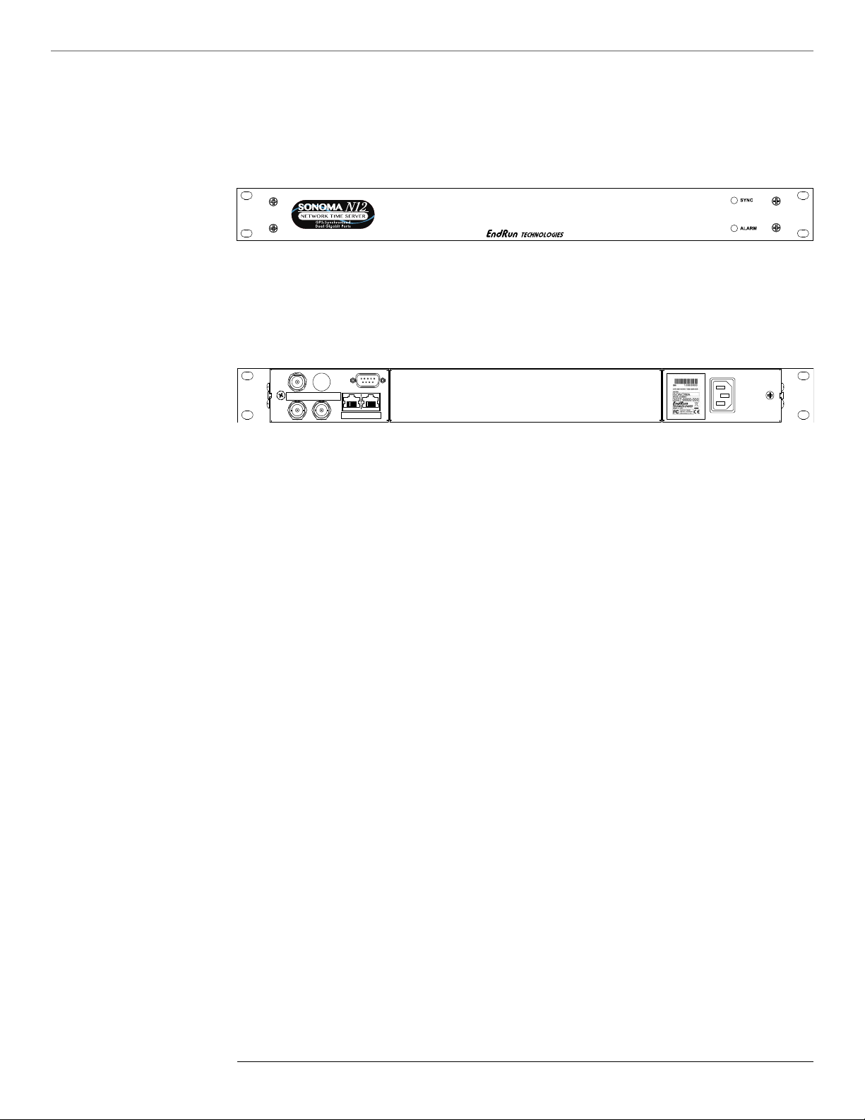
Sync LED This amber LED ashes to indicate synchronization status.
Alarm LED This red LED illuminates briey at power-up, and thereafter whenever
a serious fault condition exists.
The drawing above shows the Sonoma rear-panel in its most common conguration - with no optional outputs. However, there are a wide variety of optional outputs available. For more information on
options see Chapter 10 - Options. (For a dimensional drawing of the Sonoma chassis see Appendix
H - Specifications.) Descriptions below briey describe the standard I/O connectors:
Antenna Jack This TNC connector mates with the downlead cable from the external
antenna.
RS-232 Connector This DB9M connector provides the RS-232 serial I/O console
interface to the Sonoma. This console allows you to initialize
and maintain the Sonoma. See Chapter 9 - Console Port Control
and Status for more information including the RS-232 pin assignments.
10/100/1000Base-T Jacks These two RJ-45 connectors mate with the ethernet twisted pair cable
from the network. They are labeled with the corresponding MAC
address and either “ETH0” or “ETH1”. Integrated LEDs indicate link
speed (green) and activity (amber). The green LED will pulse once for
a speed of 10M, twice for 100M, and three times for 1G. Both ports
provide a console interface to the Sonoma. See Chapter 9 - Console
Port Control and Status for more information.
Spare Jacks These unused BNC connectors are usually labeled “SPARE”. When
(Unused) used, they will be labeled with their connector identier (A, B, or C)
and provide optional signals. Label examples are: “A-AMCODE”,
“B-1PPS”, or “C-PPO”. For more information on Sonoma
options see Chapter 10 - Options.
AC Power Input Jack This IEC 320 standard three-prong connector provides AC power.
Other power supplies are available. See Chapter 10 - Options for
more information.
6
S o n o m a U s e r M a n u a l
Page 23

Performing a Site Survey
B A S I C I N S TA L LA T I O N
Using the front panel status LED indicators, it’s easy to nd out if your Sonoma will work in your
desired location:
1. Screw the TNC plug on the end of the antenna cable onto the TNC antenna input jack on the chassis rear panel of the Sonoma.
2. Plug one end of the supplied AC power cord into an 85-270 VAC outlet.
3. Plug the other end into the AC input connector on the chassis rear panel of the Sonoma.
Place the antenna in a window, or for best performance, mount it on the roof using the supplied
mounting hardware. For detailed information on GPS antenna installation see Appendix E - Install-
ing the GPS Antenna.
Initially upon power up:
1. The unit will light the Alarm LED for about 10 seconds.
2. Then it will continuously light the Sync LED.
3. When the unit locks onto a GPS signal and begins to decode the timing data and adjust the system
oscillator, the Sync LED will ash very rapidly (about a 6 Hz rate) until the data is fully decoded and
the system oscillator is fully locked to the GPS frequency.
4. Then the Sync LED will pulse at precisely a 1 Hz rate, synchronized to UTC seconds.
At this point, the GPS Subsystem is fully synchronized, and you may proceed to permanently mounting the chassis and antenna in their desired locations.
If this sequence has not occurred within twenty-four hours, and you have mounted your antenna in a
window or your rooftop installation has poor sky visibility, you may need to provide an accurate reference position to the unit so that it can operate with only one satellite in view. If you have mounted
the antenna in a window and can easily move it to the rooftop, you should do that rst. Should you
need to provide a reference position to the unit, refer to Appendix E - GPS Reference Position and
the setgpsrefpos command for details.
If you are unable to achieve GPS lock after trying all of these suggestions, then contact EndRun Customer Support for assistance.
NOTE TO PRECISION TIME PROTOCOL (PTP) USERS
If you want to maximize timing accuracy, see Appendix E - Installing the GPS Antenna, Calibrate
Your Receiver.
7
S o n o m a U s e r M a n u a l
Page 24

9
S o n o m a U s e r M a n u a l
B A S I C I N S TA L LA T I O N
Installing the Sonoma
C H A P T E R T W O
FCC NOTICE
This equipment has been tested and found to comply with the limits for a Class A digital device, pursuant
to part 15 of the FCC Rules. These limits are designed to provide reasonable protection against harmful
interference when the equipment is operated in a commercial environment. This equipment generates,
uses, and can radiate radio frequency energy and, if not installed and used in accordance with the instruction manual, may cause harmful interference to radio communications. Operation of this equipment in a
residential area is likely to cause harmul interference in which case the user will be required to correct the
interference at his own expense.
Using standard 19” rack mounting hardware, mount the unit in the desired location. After mounting
the unit and connecting the antenna cable, verify that it still acquires and tracks a GPS signal.
CAUTION
Ground the unit properly with the supplied power cord.
The socket outlet should be installed near the equipment and be easily accessible.
Power cord is used as a disconnection device. To de-energize equipment, disconnect the power cord. If
your Sonoma has dual power supplies, then multiple power cords may be installed. To de-energize this
equipment, disconnect all power cords from the device.
Do not install the Sonoma N12 where the operating ambient temperature might exceed 122°F (50°C).
Connecting the Optional DC Power
The DC Power Input is an option. For installation instructions see Chapter 10 - Options, Connecting
the DC Power.
Connecting and Configuring Ethernet
Connect one end of the CAT-5 patch cable supplied with your Sonoma to either of the rear panel
mounted RJ-45 connector labeled 10/100/1000Base-T. Connect the other end of the patch cable to
your network through a ‘straight’ port on your switch. Do not connect it to a ‘crossover’ port on your
switch.
By factory default, the Sonoma will attempt to congure the ethernet interfaces automatically via
the Dynamic Host Conguration Protocol (DHCP). The Sonoma will attempt to set the netmask,
its IP address, the IP address of the default gateway, the domain name and the IP addresses of any
nameservers, if the DHCP server is congured to provide them. You may optionally congure the
Sonoma to also set its hostname via DHCP, if your DHCP server is congured to provide it. You can
do this by running a simple script called netconfig after your unit is up on the network.
S o n o m a U s e r M a n u a l
8
Page 25

B A S I C I N S TA L LA T I O N
If your network does use DHCP for host conguration, and you are in a hurry to get your Sonoma up
and running, you may proceed to Verifying Network Conguration to make sure that the network
parameters were set up correctly. Otherwise, it is recommended that you read the following sections
on the use of the RS-232 serial I/O port now, since they will help you in debugging any problems that
you may encounter with the automatic conguration via DHCP.
If your network does not use DHCP, you will need to congure your ethernet interfaces using the RS232 serial I/O port. The following sections contain brief descriptions on how to do that.
Configuring Ethernet with the Serial Port
To congure your ethernet interfaces with the serial port, after logging in as the root user, you must
run a simple script called netconfig. This script will prompt you for the needed information and
perform some syntax checking on your inputs. Then it will create or modify the appropriate les
needed to congure the ethernet interface. The following sections will guide you in setting up communications with the Sonoma using its RS-232 serial I/O port.
Connect the RS-232 Serial I/O Port
To test serial communications with the Sonoma you will need either a VT100 compatible terminal or
a terminal emulation program running on your computer. We will refer to either of these as “terminal” for the remainder of this instruction.
1. Disconnect power from the Sonoma.
2. Connect one end of the DB9F-to-DB9F null modem adapter cable to the serial I/O jack on the
Sonoma.
3. Connect the other end of the DB9F-to-DB9F null modem adapter cable to the terminal. If the
serial I/O port on your terminal does not have a DB9M connector, you may need to use an adapter.
Refer to Appendix H - Specifications for details on the signal wiring. If you are using a computer
for your terminal, remember which port you are using because you will need to know that in order to
set up your terminal software.
NOTE
You must use an RS-232 null-modem cable or adapter if you are connecting the Sonoma N12 to another
computer. The cable included in the shipping kit is a null-modem cable.
If your computer does not have a serial port, you can use a USB port with a USB-RS232 converter similar
to Gearmo GM-FTDI-8. First, connect the USB converter to your computer, then connect the converter to
the null-modem cable. Finally, connect the null-modem cable to the Sonoma.
Test the Serial Port
You must congure your terminal to use the serial I/O port you used in Connect the RS-232 Serial
I/O Port above. You must also congure your terminal as shown below:
9
S o n o m a U s e r M a n u a l
Page 26

C H A P T E R T W O
11
S o n o m a U s e r M a n u a l
B A S I C I N S TA L LA T I O N
• Baud Rate: 19200
• Data Bits: 8
• Parity: None
• Stop Bits: 1
• Handshaking / Flow Control: OFF (both hardware and software)
• Terminal Emulation (if any): VT100 (or similar) or Linux
After conguring these parameters in your terminal, apply power to the Sonoma. After about 20
seconds, your terminal should display something similar to this:
*************************************************************
* 6010-0066-000 Linux Bootloader v1.00 Jan 1 2013 21:24:16 *
*************************************************************
Default kernel: FACTORY
To override and boot the UPGRADE version of the kernel, type UPGRADE within 5 seconds
.....
Booting with FACTORY Kernel
Default Root File System: FACTORY
To override and boot the UPGRADE version of the Root File System, type UPGRADE within 5 seconds
.....
Booting with the FACTORY Root File System
These lines are the Linux bootloader boot prompts. These prompts will timeout after ve seconds
and the factory default Linux kernel and the factory default Sonoma root le system will be loaded.
When the Linux kernel is loaded from FLASH memory into RAM a long list of kernel-generated,
informational messages is displayed as the kernel begins execution and the various device drivers are
initialized. When the boot process completes, the Sonoma login prompt is displayed:
********************************************************************************
* Welcome to Sonoma_N12 GPS console on: Sonoma_N12.your.domain
* Tue Feb 20 2013 21:47:03 UTC
********************************************************************************
Sonoma_N12 login:
Here you may log in as “ntpuser” with password “Praecis” or you may log in as the “root” user with
password “endrun_1”. When logged in as “ntpuser”, you may check status information and view log
les but you will not be able to modify any system settings or view secure les. In order to perform
system setup procedures, which includes conguring the IP network settings, you must log in as the
“root” user. After correctly entering the password at this prompt,
password:
the sign on message is shown. It identies the host system as Sonoma N12 GPS and shows the software part number, version and build date. The out-of-the-box hostname is set to “Sonoma_N12”, and
the domainname is set to “your.domain”.
Sonoma_N12 GPS 6010-0065-000 v 1.00 Sat Jan 19 14:17:44 UTC 2013
Sonoma_N12 GPS (root@Sonoma_N12:~)->
This last line is the standard Sonoma N12 GPS prompt. After conguring the unit, you should
change the passwords using the Linux passwd command issued from the prompt.
S o n o m a U s e r M a n u a l
10
Page 27

B A S I C I N S TA L LA T I O N
If you do not see characters displayed by your terminal program within 30 seconds after the unit is
powered up, you must troubleshoot your setup. An incorrectly wired cable or incorrect port setting in
your terminal emulation program are the most common problems. Refer to Appendix H - Specifica-
tions for the signal connections for the Sonoma.
Once you have successfully established communications with the Sonoma, you may proceed to
congure the network parameters using netconfig (see below). Then you can communicate with
the Sonoma over the network using telnet or ssh and synchronize your network computers to UTC
using NTP.
Using netconfig to Set Up Your IP
The script le netconfig will congure the TCP/IP network parameters for your Sonoma.
NOTE
When setting up the IP addresses on both network port 0 (eth0) and 1 (eth1):
1. Be sure that they are NOT on the same subnet.
2. Configure the default gateway on either port 0 (eth0) or port 1 (eth1), BUT NOT BOTH.
NOTE
If you want to use the HTTPS Interface, then be sure to configure the name server IP address during the
netconfig process. The HTTPS Interface will not operate properly if this is configured incorrectly. Only
one name server is required, but two gives some redundancy.
The following shows the beginning of the netconfig interactive script:
11
S o n o m a U s e r M a n u a l
Page 28

C H A P T E R T W O
13
S o n o m a U s e r M a n u a l
B A S I C I N S TA L LA T I O N
*******************************************************************************
*************** Sonoma_N12 GPS IPV4/IPV6 Network Configuration ****************
*******************************************************************************
* *
* This script will configure the TCP/IPV4/IPV6 network parameters for your *
* Sonoma_N12 GPS. We will first configure IPV4 and then IPV6. Your *
* Sonoma_N12 GPS has two ethernet interfaces, called eth0 and eth1. For *
* each of IPV4 and IPV6, we will first configure eth0 and then eth1. *
* *
* You can choose to keep the existing configuration of either interface and *
* reconfigure the other. You can also choose to “unconfigure” either of *
* the two interfaces if both are not needed in your application. *
* *
* You will be able to reconfigure your system at any time by typing: *
* *
* netconfig *
* *
* The settings you make now will not take effect until you reboot your *
* Sonoma_N12 GPS, so if you make a mistake, just re-run this script before *
* rebooting. *
* *
* You will be prompted to enter your IPV4/IPV6 network parameters now. *
* *
*******************************************************************************
*******************************************************************************
Configure IPV4 for either eth0 or eth1?
(Answer yes to continue on and reconfigure either eth0 or eth1 for IPV4.)
(Answer no to “unconfigure” both eth0 and eth1 for IPV4. Only the
IPV4 loopback interface will be setup.) ([y]es, [n]o):
After conguring your ethernet interfaces, you should shutdown the Sonoma and reboot it by issuing
this command at the prompt:
Sonoma N12 GPS(root@Sonoma_N12:~)-> reboot
Verify Network Configuration
If you are using the RS-232 serial I/O port to communicate with the Sonoma, you will be able to see
the kernel-generated boot messages when the unit reboots. You should note the lines
Configuring eth0 as 192.168.1.120...
Configuring eth1 as 192.168.5.1...
if you have set up a static IP address, or these lines
Attempting to configure eth0 by contacting a DHCP server...
Attempting to configure eth1 by contacting a DHCP server...
if you are using DHCP. These appear near the end of the kernel generated boot messages.
If you are using DHCP and are not using the RS-232 serial I/O port, you will have to check the
DHCP conguration information maintained by your DHCP server to determine the expected IP address and log in to the Sonoma using telnet or ssh to verify successful DHCP conguration. Refer
to the subsequent topics in this section Using Telnet and Using SSH, for details on logging in to the
Sonoma that way. Once you have logged in, you may perform the following checks.
S o n o m a U s e r M a n u a l
12
Page 29

B A S I C I N S TA L LA T I O N
If you are not using DHCP, the IP address shown should match the static IP address which you
entered during the netconfig procedure. If so, log in as “root” at the login prompt and check the
other conguration parameters using ifconfig:
Sonoma N12 GPS(root@host:~)-> ifconfig
eth0 Link encap:Ethernet HWaddr 00:0e:fe:01:00:1c
inet addr:192.168.1.120 Bcast:192.168.1.255 Mask:255.255.255.0
UP BROADCAST RUNNING MULTICAST MTU:1500 Metric:1
RX packets:9694 errors:0 dropped:970 overruns:0 frame:0
TX packets:459 errors:0 dropped:0 overruns:0 carrier:0
collisions:0 txqueuelen:1000
RX bytes:829805 (810.3 KiB) TX bytes:50242 (49.0 KiB)
Interrupt:11
eth1 Link encap:Ethernet HWaddr 00:0e:fe:01:00:1d
inet addr:192.168.5.1 Bcast:192.168.5.255 Mask:255.255.255.0
UP BROADCAST RUNNING MULTICAST MTU:1500 Metric:1
RX packets:10143 errors:0 dropped:970 overruns:0 frame:0
TX packets:0 errors:0 dropped:0 overruns:0 carrier:0
collisions:0 txqueuelen:1000
RX bytes:881081 (860.4 KiB) TX bytes:0 (0.0 B)
Interrupt:15
lo Link encap:Local Loopback
inet addr:127.0.0.1 Mask:255.0.0.0
inet6 addr: ::1/128 Scope:Host
UP LOOPBACK RUNNING MTU:16436 Metric:1
RX packets:5808 errors:0 dropped:0 overruns:0 frame:0
TX packets:5808 errors:0 dropped:0 overruns:0 carrier:0
collisions:0 txqueuelen:0
RX bytes:728178 (711.1 KiB) TX bytes:728178 (711.1 KiB)
Pay particular attention to the settings shown for eth0 and eth1, in particular the Mask: setting,
which should match that which is appropriate for your network. Now check the remaining conguration parameters using route:
Sonoma N12 GPS(root@host:~)-> route
Kernel IP routing table
Destination Gateway Genmask Flags Metric Ref Use Iface
default 192.168.1.1 0.0.0.0 UG 1 0 0 eth0
loopback * 255.0.0.0 U 0 0 0 lo
localnet * 255.255.255.0 U 0 0 0 eth0
192.168.5.0 * 255.255.255.0 U 0 0 0 eth1
Here you are interested in the default gateway address. It should match the appropriate one for your
network. If so, then the ethernet interface of your Sonoma has been successfully congured to operate on your network and you are ready to check operation of the Sonoma over the network. If not,
you should recheck your conguration and/or repeat the netconfig procedure.
If you have congured a nameserver(s) for your network, you may check that by issuing this command:
Sonoma N12 GPS(root@host:~)-> cat /etc/resolv.conf
search your.domain
nameserver 192.168.1.1
nameserver 192.168.1.2
13
S o n o m a U s e r M a n u a l
Page 30

C H A P T E R T W O
15
S o n o m a U s e r M a n u a l
B A S I C I N S TA L LA T I O N
Which displays the contents of the /etc/resolv.conf le containing the domain name you entered previ-
ously using netconfig, and the nameserver IP address(es) to use for that domain.
Check Network Operation
With your Sonoma network parameters properly congured, you are ready to test the setup using
ping from a server or workstation that is able to access the network connected to the Sonoma. Al-
ternatively, you could ping one of your servers or workstations from the Sonoma prompt to test the
setup.
Once you have successfully established network communications with the Sonoma, you may perform
all maintenance and monitoring activities via telnet and ftp. The Sonoma provides both client and
server operation using telnet. For security reasons, only client operation is supported using ftp.
You may also monitor the Sonoma via the HTTPS interface (see Chapter 7 - HTTPS).
Security conscious users will want to use ssh, the secure shell replacement for telnet, as the login
means. The companion utility, scp provides a secure replacement for ftp as a means of transferring
les to and from the Sonoma. Both of these protocols are supported in the Sonoma via the OpenSSH
implementations for Linux. Refer to Chapter 5 - Security, Open SSH for more information about the
secure shell protocol.
Using Telnet
When establishing a telnet connection with your Sonoma, logging in directly as root is not permitted. This is a security measure that makes it slightly more difcult to gain access by simply trying
passwords, since it is also necessary to know the name of a user. When you initiate a telnet session
with the Sonoma, this banner will be displayed:
********************************************************************************
* Welcome to Sonoma_N12 GPS telnet console on: host.your.domain
********************************************************************************
host login:
Here you may log in as “ntpuser” with password “Praecis”. When logged in as “ntpuser”, you may
check status information and view log les but you will not be able to modify any system settings or
view secure les. After correctly entering the password at this prompt,
Password:
the sign on message is shown. It identies the host system as Sonoma GPS and shows the software
part number, version and build date:
Sonoma_N12 GPS 6010-0065-000 v 1.00 Sat Jan 19 14:17:44 UTC 2013
Sonoma_N12 GPS (root@host:~)->
This last line is the standard Sonoma GPS prompt. After conguring the unit, you should change the
passwords using the Linux passwd command issued from the prompt.
To gain root access, you must now issue the “super user” command at the prompt:
S o n o m a U s e r M a n u a l
14
Page 31

B A S I C I N S TA L LA T I O N
Sonoma_N12 GPS(root@host:~)-> su root
You will then be prompted for the password, which is “endrun_1”, and be granted root access to the
system. To leave “super user” mode, issue the command exit. Issuing exit again will close the
telnet session.
Using SSH
When establishing a ssh connection with your Sonoma, logging in directly as root is permitted.
When you log in as root via a ssh session with the Sonoma, this banner will be displayed:
*******************************************************************************
* Welcome to the Sonoma_N12 GPS SSH console on: host.your.domain
*******************************************************************************
[email protected]’s password:
Here you may log in as “root” with password “endrun_1”. After correctly entering the password
the sign on message is shown. It identies the host system as Sonoma and shows the software part
number, version and build date:
Sonoma_N12 GPS 6010-0065-000 v 1.00 Sat Jan 19 14:17:44 UTC 2013
Sonoma_N12 GPS (root@host:~)->
This last line is the standard Sonoma N12 GPS prompt. After conguring the unit, you should
change the passwords using the Linux passwd command issued from the prompt.
Issuing exit will close the ssh session.
Using HTTPS
You may monitor the status of the Sonoma via the HTTPS interface. For security reasons, you may
not change any settings via the HTTPS interface. See Chapter 7 - HTTPS for more information.
IMPORTANT
SSH, Telnet, SNMP and HTTPS are all enabled with default passwords. To ensure security, change the
passwords or disable the protocols.
To change the passwords for SSH, Telnet and HTTPS use the Linux passwd command. To change the
passwords/community strings for SNMP see Chapter 6 - SNMP.
To disable Telnet, SSH, SNMP and HTTPS see Chapter 5 - Security, Disable Protocols.
15
S o n o m a U s e r M a n u a l
Page 32

C H A P T E R T W O
This page intentionally left blank.
16
S o n o m a U s e r M a n u a l
Page 33

"Smarter Timing Solutions"
Configuring the NTP Server
Chapter
Three
Network Time Protocol (NTP)
This chapter describes how to congure the Sonoma as an NTP Server. It also includes brief instruction for setting up NTP Clients on your Unix-like or Windows platform. This manual is not a ‘HowTo’ on installing and using NTP. Only basic approaches to NTP client conguration for operation
with the Sonoma will be described. If you have never used NTP, then you should spend some time
reading the on-line documents, especially the Distribution Notes, FAQ and Conguration subject
matter, which are available at:
http://www.ntp.org
A simple introduction to NTP is here:
http://www.endruntechnologies.com/pdf/NTP-Intro.pdf
Configuring the Sonoma as a Stratum 1 Server
To congure your Sonoma as a Stratum 1 NTP Server you must have successfully completed the
Basic Installation procedures in Chapter 2. By default, the Sonoma is congured to respond to NTP
requests from clients that may or may not be using MD5 authentication. If the clients are using
MD5 authentication, they must be congured properly with the same MD5 authentication keys as
the Sonoma. If you need to modify the factory default Sonoma MD5 keys (recommended) or set up
broadcast/multicast operation, then you will need to recongure the NTP subsystem. You may perform the conguration from either a telnet or ssh session or the local RS-232 console.
NOTE
If you would like to configure your server for multicast operation, configure it as you would for broadcast
operation, with the exception that you must enter this specific NTP IPV4 multicast address: 224.0.1.1, or
this specific IPV6 multicast address ff05::101, when you are prompted to enter the broadcast address.
Configuring NTP Using the Network Interface or Serial Port
The following shows the question and answer conguration utility called ntpconfig. The userentered responses are shown in a larger font size.
Sonoma_N12 GPS(root@Sonoma_N12:~)-> ntpcong
17
S o n o m a U s e r M a n u a l
Page 34

C H A P T E R T H R E E
19
S o n o m a U s e r M a n u a l
N E T W O R K T I M E P R O T O C O L ( N T P )
*******************************************************************************
**********************Network Time Protocol Conguration**********************
*******************************************************************************
* *
* This script will allow you to configure the ntp.conf and ntp.keys files *
* that control Sonoma_N12 GPS NTP daemon operation. *
* *
* You will be able to create new MD5 authentication keys which are stored *
* in the ntp.keys file. *
* *
* You will be able to update the authentication related commands in the *
* ntp.conf file. *
* *
* You will be able to configure the “broadcast” mode of operation, with *
* or without authentication. If you supply the multicast address instead *
* of your network broadcast address, then you will be able to configure *
* the time-to-live of the multicast packets. *
* *
* The changes you make now will not take effect until you re-boot the *
* Sonoma_N12 GPS. If you make a mistake, just re-run ntpconfig prior to *
* re-booting. *
* *
* You will now be prompted for the necessary set up parameters. *
* *
*******************************************************************************
*******************************************************************************
---MD5 Keyfile Configuration
Would you like to create a new ntp.keys file? ([y]es, [n]o) y
You will be prompted for a key number (1 - 65534), then the actual key.
When you have entered all of the keys that you need, enter zero at the next
prompt for a key number.
MD5 keys may contain from 1 to 31 ASCII characters. They may not contain
contain SPACE, TAB, LF, NULL, or # characters! If the key is longer than
20 characters, then only the valid hexadecimal characters
(0 - 9, a, b, c, d, e, f) may be used.
Enter a key number (1-65534) or 0 to quit: 1
Enter the key (1-31 ASCII characters): EndRun_Technologies
Writing key number: 1 and Key: EndRun_Technologies to ntp.keys
Enter a key number (1-65534) or 0 to quit: 2
Enter the key (1-31 ASCII characters): Sonoma
Writing key number: 2 and Key: Sonoma to ntp.keys
Enter a key number (1-65534) or 0 to quit: 0
---NTP Authentication Configuration
Do you want authentication enabled using some or all of the keys in
the ntp.keys file? ([y]es, [n]o) y
S o n o m a U s e r M a n u a l
18
Page 35

N E T W O R K T I M E P R O T O C O L ( N T P )
You will be prompted for the key numbers (1 - 65534), that you want NTP to
“trust”. The key numbers you enter must exist in your ntp.keys file. If you
do not want to use some of the keys in your ntp.keys file, do not enter them
here. NTP will treat those keys as “untrusted”.
Clients that use any of the “trusted” keys in their NTP polling packets will
receive authenticated replies from the Sonoma_N12 GPS. When you have entered
all of the “trusted keys” that you need, enter zero at the next prompt for a
key number.
Enter a trusted key number (1-65534) or 0 to quit: 1
Enter a trusted key number (1-65534) or 0 to quit: 2
Enter a trusted key number (1-65534) or 0 to quit: 0
---NTP Broadcast/Multicast Configuration
Would you like to enable broadcast/multicast server operation? ([y]es, [n]o) y
Set the network broadcast/multicast address for the Sonoma_N12 GPS
to use. For broadcast mode on IPV4 networks, this address is
the all 1’s address on the sub-net.
Example: 111.112.113.255
On IPV6 networks, there is more than one way to
define a range of multicast addresses:
Example: ff05::1 (all nodes on the local site)
Example: ff02::1 (all nodes on the local link)
There are specific multicast addresses assigned for NTP Operation:
For IPV4 multicast operation, it is this specific address-> 224.0.1.1
For IPV6 multicast operation, it is this specific site scope address-> ff05::101
Enter IP address for NTP broadcast/multicast operation
(aaa.bbb.ccc.ddd or aaaa::bbbb ): 224.0.1.1
You have selected multicast operation. Enter the TTL value that is
needed for multicast packets on your network (1, 32, 64, 96, 128, 160, 192, 224): 32
It is highly recommended that authentication be used if you are using NTP
in broadcast/multicast mode. Otherwise clients may easily be “spoofed” by
a fake NTP server. You can specify an MD5 key number that the Sonoma_N12 GPS
will use in its broadcast/multicast packets. The clients on your network must
be configured to use the same key.
Would you like to specify an MD5 key number to use with
broadcast/multicast mode? ([y]es, [n]o) y
Enter the MD5 key number to use (1-65534): 2
*******************************************************************************
*******************************************************************************
* *
* The Sonoma_N12 GPS Network Time Protocol configuration has been updated. *
* *
* Please re-boot now for the changes to take effect. *
* *
*******************************************************************************
*******************************************************************************
19
S o n o m a U s e r M a n u a l
Page 36

C H A P T E R T H R E E
21
S o n o m a U s e r M a n u a l
N E T W O R K T I M E P R O T O C O L ( N T P )
Configuring the Sonoma as a Stratum 2 Server
Operating the Sonoma as a Stratum 1 Server is the recommended mode. However, there are times
when Stratum 2 operation is a good strategy:
1. When you want a backup source of time. In this case, Sonoma will operate as a Stratum 1
Server as long as it is locked to the GPS signal. If it loses the signal, then Sonoma will start to drift
away from “perfect” time. Eventually, when it has drifted 10 milliseconds, it reach the unlocked condition and stop serving time on your network. If you have Sonoma congured for Stratum 2 operation, then it will continue serving time, using another Time Server as its reference. If Sonoma is later
able to acquire lock on the GPS signal again, it will switch back to Stratum 1 operation.
2. When you want your Sonoma to serve accurate time, but you don’t want to use the antenna (for
some reason). In this case, Sonoma can operate solely as a Stratum 2 server, with no antenna connected.
Since there are innumerable ways to congure your network with Stratum 2 servers, specic insructions for how to do that are beyond the scope of this manual. General instructions on how to edit the
ntp.conf le are below.
Edit ntp.conf File
You must edit the ntp.conf le in order to point your Stratum 2 server at a Stratum 1 server. Edit /etc/
ntp.conf and add your server line(s). (See Appendix C - Helpful Linux Information for information
on a simple editor.) Here is an example:
server 192.168.1.1
Or, if you have set up a domain name server via netconfig, here is another example:
server your.timeserver.com
IMPORTANT
Do not remove the server lines for the refclock. Even if your Time Server is not connected to an antenna,
the refclock server lines must remain.
Now save the edited le and copy it to the non-volatile ash partition with this command:
cp -p /etc/ntp.conf /boot/etc
Mask Alarm
In Stratum 1 operation an alarm will be indicated when there is a loss of signal or if the antenna is
not connected. For Stratum 2 operation you may not want to see these alarms. You can mask them
(prevent them from showing) by using the console port (serial/network) commands setsigfltmask
and setantfltmask.
20
S o n o m a U s e r M a n u a l
Page 37

Setting Up NTP Clients on Unix-like Platforms
N E T W O R K T I M E P R O T O C O L ( N T P )
To congure your Unix-like computer to use your Sonoma Time Server, you must have successfully completed the NTP Server basic installation procedure described above. It is expected that you
are, or have access to, a capable Unix/Linux system administrator and know more than a little about
installing distributions from source code. Installation must be performed by a user with root priviledges on the system.
If you have access to a usenet news server, many problems may be solved by the helpful people who
participate in the Internet news group devoted to NTP at comp.protocols.time.ntp.
Three methods of using the Sonoma with NTP clients on Unix-like platforms will be described:
Basic: This is the simplest, and will operate without MD5 authentication. NTP beginners should
always perform this setup rst.
MD5: This method is trickier only because MD5 keys must be set up and distributed accurately to
the NTP clients in a secure way. The Sonoma is factory congured to authenticate its replies to NTP
MD5 clients using its default set of keys.
Broadcast/Multicast: This method simplies conguration of the clients on large networks since
specic server addresses need not be congured in each client’s /etc/ntp.conf le. It can be congured either with or without MD5 authentication. However, it is highly recommended that authentication be congured when using broadcast/multicast mode due to the relative ease with which a fake
NTP server can take over the clock setting of the broadcast/multicast clients on the network.
Unix-like Platforms: Basic NTP Client Setup
Basic setup is relatively simple, if:
• You have been able to successfully communicate with the Sonoma on your network.
• You have installed NTP on your client computer.
Configure NTP
You must edit the ntp.conf le which ntpd, the NTP daemon, looks for by default in the the /etc
directory. Add this line to the ntp.conf le:
server 192.168.1.120
This line tells ntpd to use the NTP server at address 192.168.1.120 in addition to any other servers
which might also be congured in the client’s ntp.conf le.
Restart ntpd to have it begin using the Sonoma server. Use the NTP utility ntpq to check that ntpd
is able to communicate with the Sonoma. After issuing the command
ntpq
you will see the ntpq command prompt:
21
S o n o m a U s e r M a n u a l
Page 38

C H A P T E R T H R E E
23
S o n o m a U s e r M a n u a l
N E T W O R K T I M E P R O T O C O L ( N T P )
ntpq>
Use the command
peers
to display the NTP peers which your computer is using. One of them should be the Sonoma server
which you have just congured. You should verify that it is being ‘reached’. (You may have to
continue issuing the peers command for a minute or two before you will see the ‘reach’ count increment.) If you have other peers congured, verify that the offset information for the Sonoma server
peer and your other peers is in agreement to within a few milliseconds, assuming that the other peers
are synchronized to that level of accuracy.
It may also be useful to start the NTP daemon in ‘debug’ mode (ntpd -d) to conrm successful conguration. Refer to the NTP documentation for detailed usage of these debug utilities.
Unix-like Platforms: MD5 Authenticated NTP Client Setup
MD5 authenticated setup is relatively simple, if:
• You have been able to successfully communicate with the Sonoma on your network.
• Your Sonoma has been congured to perform authentication either by factory default, or by running the ntpconfig shell script. The example Sonoma authentication conguration shown in Con-
figuring NTP Using the Network Interface or Serial Port above, will be assumed in the example
conguration commands shown here.
• You have installed NTP on your client computer.
• You have successfully performed the Unix-like Platforms: Basic NTP Client Setup on your client
computer.
Create the ntp.keys File
You must create a le named ntp.keys in the /etc directory. It must be a copy of the one residing in
the /etc directory of your Sonoma. You can telnet into your Sonoma and start an ftp session with
your client computer to send the Sonoma’s /etc/ntp.keys le to your client computer, use the secure
copy utility scp, or you can just use a text editor on your client computer to create an equivalent le.
IMPORTANT
Handling of the /etc/ntp.keys file is the weak link in the MD5 authentication scheme. It is very important that it is owned by root and not readable by anyone other than root.
After transferring the le by ftp, and placing it in the /etc directory on the client computer, issue
these two commands at the shell prompt:
chown root.root /etc/ntp.keys
chmod 600 /etc/ntp.keys
S o n o m a U s e r M a n u a l
22
Page 39

N E T W O R K T I M E P R O T O C O L ( N T P )
Configure NTP
You must edit the ntp.conf le which ntpd, the NTP daemon, looks for by default in the /etc directory. Assuming that you have created two trusted keys as shown in Configuring the NTP Server Using
the Network Interface or Serial Port above, add these lines to the end of the ntp.conf le:
keys /etc/ntp.keys
trustedkey 1 2
Modify the line added previously in Unix-like Platforms: Basic NTP Client Setup so that authentication will be used with the Sonoma server using one of the trusted keys, in this example, key # 1:
server 192.168.1.120 key 1
Restart ntpd to have it begin using the Sonoma server with MD5 authentication. Use the NTP utility
ntpq to check that ntpd is able to communicate with the Sonoma. After issuing the command
ntpq
you will see the ntpq command prompt:
ntpq>
Use the command
peers
to display the NTP peers which your computer is using. One of them should be the Sonoma server
which you have just congured. You should verify that it is being ‘reached’. (You may have to continue issuing the peers command for a minute or two before you will see the ‘reach’ count increment.)
You can verify that authentication is being used by issuing the command
associations
to display the characteristics of the client server associations. In the “auth” column of the display,
you should see “OK” for the row corresponding to the Sonoma server. If you see “bad”, you should
wait a few minutes to be sure that there is a problem since “bad” is the initial state of this setting. If
the “bad” indication persists then you must check your conguration for errors. Typically this is due
to a typing error in creating the /etc/ntp.keys le on the client that causes a mismatch between the
keys being used by the server and client. (If you transfer the le by ftp or scp, this shouldn’t be a
problem.) It is also possible to have a typing error in the /etc/ntp.conf le that causes the needed key
to not be included in the “trustedkey” list.
Unix-like Platforms: Broadcast/Multicast NTP Client Setup
Broadcast/multicast client setup is relatively simple, if:
• You have been able to successfully communicate with the Sonoma on your network.
• Your Sonoma has been congured to perform broadcasts or multicasts by running the ntpconfig
shell script. (This is not the factory default conguration, so be sure to run ntpconfig.) If you are
going to use MD5 authentication, your Sonoma must have been congured to operate with authenti-
23
S o n o m a U s e r M a n u a l
Page 40

C H A P T E R T H R E E
25
S o n o m a U s e r M a n u a l
N E T W O R K T I M E P R O T O C O L ( N T P )
cation in the broadcast/multicast mode, and you must know which of the trusted keys it is using for
broadcast/multicast operation. The example Sonoma conguration shown in Configuring the NTP
Server above will be assumed in the example conguration commands shown here.
• You have installed NTP on your client computer.
• You have successfully performed the Unix-like Platforms: MD5 Authenticated NTP Client Setup
on your client computer, if you plan to use MD5 authentication.
Configure NTP Client for Broadcast
You must edit the ntp.conf le which ntpd, the NTP daemon, looks for by default in the /etc directory. Assuming that your Sonoma server has been congured to use key 2 for broadcast authentication as shown in the example in Configuring the NTP Server above, make sure that key 2 is included
in the trustedkey line, and add this line to the end of the ntp.conf le:
broadcastclient
If you are not using MD5 authentication, you would add these lines:
disable auth
broadcastclient
You may remove the line added previously in Unix-like Platforms: Basic NTP Client Setup:
server 192.168.1.120
or the authenticated version added in Unix-like Platforms: MD5 Authenticated NTP Client Setup:
server 192.168.1.120 key 1
Configure NTP Client for Multicast
You must edit the ntp.conf le which ntpd, the NTP daemon, looks for by default in the the /etc
directory. And add these lines for multicast:
multicastclient 224.0.1.1
or for IPv6:
multicastclient ff05::101
If you are not using MD5 authentication, you would add these lines:
disable auth
multicastclient 224.0.1.1
or for IPv6:
disable auth
multicastclient ff05::101
24
S o n o m a U s e r M a n u a l
Page 41

N E T W O R K T I M E P R O T O C O L ( N T P )
You may remove the line added previously in Unix-like Platforms: Basic NTP Client Setup:
server 192.168.1.120
or the authenticated version added in Unix-like Platforms: MD5 Authenticated NTP Client Setup:
server 192.168.1.120 key 1
Test Broadcast/Multicast
Restart ntpd to have it begin using the Sonoma as a broadcast or multicast server. Use the NTP utility ntpq to check that ntpd is able to communicate with the Sonoma. After issuing the command
ntpq
you will see the ntpq command prompt:
ntpq>
Use the command
peers
to display the NTP peers which your computer is using. One of them should be the Sonoma server
which you have just congured. You should verify that it is being ‘reached’. (You may have to continue issuing the peers command for a minute or two before you will see the ‘reach’ count increment.)
If you are using authentication, you can verify that authentication is being used by issuing the command
associations
to display the characteristics of the client server associations. In the “auth” column of the display,
you should see “OK” for the row corresponding to the Sonoma server. If you see “bad”, you should
wait a few minutes to be sure that there is a problem since “bad” is the initial state of this setting. If
the “bad” indication persists then you must check your conguration for errors. Typically this is due
to a typing error in creating the /etc/ntp.keys le on the client that causes a mismatch between the
keys being used by the server and client. (If you transfer the le by ftp or scp, this shouldn’t be a
problem.) It is also possible to have a typing error in the /etc/ntp.conf le that causes the needed key
to not be included in the “trustedkey” list.
25
S o n o m a U s e r M a n u a l
Page 42

27
S o n o m a U s e r M a n u a l
N E T W O R K T I M E P R O T O C O L ( N T P )
Setting Up NTP Clients on Windows
C H A P T E R T H R E E
To congure your Windows computer to use your Sonoma Time Server, you must have successfully
completed the procedures in Configuring the NTP Server above. Client installation must be performed by a user with administrative priviledges.
If you have access to a usenet news server, many problems may be solved by the helpful people who
participate in the Internet news group devoted to NTP at comp.protocols.time.ntp.
Three methods of using the Sonoma with NTP clients on Windows platforms will be described:
Basic: This is the simplest, and will operate without MD5 authentication. NTP beginners should
always perform this setup rst.
MD5: This method is trickier only because MD5 keys must be set up and distributed accurately to
the NTP clients in a secure way. The Sonoma is factory congured to authenticate its replies to NTP
MD5 clients using its default set of keys.
Broadcast/Multicast: This method simplies conguration of the clients on large networks since
specic server addresses need not be congured in each client’s ntp.conf le. It can be congured
either with or without MD5 authentication. However, it is highly recommended that authentication
be congured when using broadcast/multicast mode due to the relative ease with which a fake NTP
server can take over the clock setting of the broadcast/multicast clients on the network.
Windows: Basic NTP Client Setup
The two most common NTP clients on Windows platforms are described below. Information on
other NTP Client software is available at:
http://www.endruntechnologies.com/ntp-client.htm
Windows: w32time
Windows uses a time service called w32time which is automatically enabled by default during
Windows installation. w32time.exe synchronizes time in different ways, depending on the network
implementation used. When peer-to-peer networking is used, then each individual workstation synchronizes to the NTP Server.
However, the most common method is with Windows Domain Networking. In this case, you must
congure the Primary Domain Controller (PDC) to synchronize to the NTP Server. All other servers
and workstations in the domain synchronize to the PDC. The default Windows installation procedure
automatically congures workstations and servers to synchronize to the controlling PDC. So, only
the PDC needs to be congured to synchronize to the NTP Server.
Windows: ntpd
For more precise timekeeping you should use ntpd. An easy way to install ntpd is by using a thirdparty NTP compilation. A list for Windows is at this link:
S o n o m a U s e r M a n u a l
26
Page 43

N E T W O R K T I M E P R O T O C O L ( N T P )
http://support.ntp.org/bin/view/Main/ExternalTimeRelatedLinks
Configure NTP
Directory path names are not given in the instructions below because there are multiple ways to
install ntpd and multiple versions of Windows.
After installing ntpd, you must edit the ntp.conf le by adding a line similar to this:
server 192.168.1.120
This line tells ntpd.exe to use the NTP server at address 192.168.1.120 in addition to any other
servers which might also be congured in the ntp.conf le.
Restart ntpd.exe to have it begin using the Sonoma server. By default, the NTP installation program installs ntpd.exe as a service called Network Time Protocol, and starts it. You must use the
Services utility in Control Panel to stop the Network Time Protocol service and then restart it.
Use the NTP utility ntpq.exe to check that ntpd.exe is able to communicate with the Sonoma.
From a console window, after issuing the command
ntpq
you will see the ntpq.exe command prompt:
ntpq>
Use the command
peers
to display the NTP peers which your computer is using. One of them should be the Sonoma server
which you have just congured. You should verify that it is being ‘reached’. (You may have to
continue issuing the peers command for a minute or two before you will see the ‘reach’ count increment.) If you have other peers congured, verify that the offset information for the Sonoma server
peer and your other peers is in agreement to within a few milliseconds, assuming that the other peers
are synchronized to that level of accuracy.
It may also be useful to start the NTP daemon in ‘debug’ mode (ntpd -d) to conrm successful conguration. Refer to the NTP documentation for detailed usage of these debug utilities.
Windows: MD5 Authenticated NTP Client Setup
MD5 authenticated setup is relatively simple, if:
• You have been able to successfully communicate with the Sonoma on your network.
• Your Sonoma has been congured to perform authentication either by factory default, or by
running the ntpconfig shell script. The example Sonoma authentication conguration shown in
27
S o n o m a U s e r M a n u a l
Page 44

C H A P T E R T H R E E
29
S o n o m a U s e r M a n u a l
N E T W O R K T I M E P R O T O C O L ( N T P )
Configuring the NTP Server above will be assumed in the example conguration commands shown
here.
• You have installed NTP on your client computer.
• You have successfully performed the Windows: Basic NTP Client Setup on your client computer.
Create the ntp.keys File
You must create a le named ntp.keys in the /program files/ntp/etc directory (for example). It must
be a copy of the one residing in the /etc directory of your Sonoma. You can telnet into your Sonoma and start an ftp session with your client computer to send the Sonoma /etc/ntp.keys le to your
client computer, or use the secure copy utility scp, or use a text editor to create the equivalent le.
Although you should rst test your setup using the factory default /etc/ntp.keys le in your Sonoma
server, you should create your own keys after you understand the process and have your clients operating correctly with the default le.
IMPORTANT
Handling of the \program files\ntp\etc\ntp.keys file is the weak link in the MD5 authentication
scheme. It is very important that it is owned by “administrator” and not readable by anyone other than
“administrator”.
After transferring the file, make sure that its security properties are set such that it is readable only by the
“administrator”.
Configure NTP
Add these lines to the end of the ntp.conf le, but substitute your particular directory path for the one
shown (program files\ntp\etc):
keys \program files\ntp\etc\ntp.keys
trustedkey 1 2
Modify the line added previously in Windows: Basic NTP Client Setup so that authentication will be
used with the Sonoma server using one of the trusted keys, in this case, key # 1:
server 192.168.1.120 key 1
Restart ntpd.exe to have it begin using the Sonoma server with MD5 authentication. By default,
the NTP installation program installs ntpd.exe as a service called Network Time Protocol, and starts
it. You must use the Services utility in Control Panel to stop the Network Time Protocol service and
then restart it.
Use the NTP utility ntpq.exe to check that ntpd.exe is able to communicate with the Sonoma.
From a console window, after issuing the command
ntpq
S o n o m a U s e r M a n u a l
28
Page 45

N E T W O R K T I M E P R O T O C O L ( N T P )
you will see the ntpq.exe command prompt:
ntpq>
Use the command
peers
to display the NTP peers which your computer is using. One of them should be the Sonoma server
which you have just congured. You should verify that it is being ‘reached’. (You may have to continue issuing the peers command for a minute or two before you will see the ‘reach’ count increment.)
You can verify that authentication is being used by issuing the command
associations
to display the characteristics of the client server associations. In the “auth” column of the display,
you should see “OK” for the row corresponding to the Sonoma server. If you see “bad”, you should
wait a few minutes to be sure that there is a problem since “bad” is the initial state of this setting. If
the “bad” indication persists then you must check your conguration for errors. Typically this is due
to a typing error in creating the ntp.keys le on the client that causes a mismatch between the keys
being used by the server and client. (If you transfer the le by ftp or scp, this shouldn’t be a problem.) It is also possible to have a typing error in the ntp.conf le that causes the needed key to not be
included in the “trustedkey” list.
Windows: Broadcast/Multicast NTP Client Setup
Broadcast/multicast client setup is relatively simple, if:
• You have been able to successfully communicate with the Sonoma on your network.
• Your Sonoma has been congured to perform broadcasts or multicasts by running the ntpconfig
shell script. (This is not the factory default conguration, so be sure to run ntpconfig.) If you are
going to use MD5 authentication, your Sonoma must have been congured to operate with authentication in the broadcast/multicast mode, and you must know which of the trusted keys it is using for
broadcast/multicast operation. The example Sonoma conguration shown in Configuring the NTP
Server above will be assumed in the example conguration commands shown here.
• You have installed NTP on your client computer.
• You have successfully performed the Windows: MD5 Authenticated NTP Client Setup on your
client computer, if you plan to use MD5 authentication.
Configure NTP Client for Broadcast
You must edit the ntp.conf le. Assuming that your Sonoma server has been congured to use key 2
for broadcast authentication as shown in the example in Configuring the NTP Server above, make
sure that key 2 is included in the trustedkey line, and add this line to the end of the ntp.conf le:
broadcastclient
29
S o n o m a U s e r M a n u a l
Page 46

C H A P T E R T H R E E
31
S o n o m a U s e r M a n u a l
N E T W O R K T I M E P R O T O C O L ( N T P )
If you are not using MD5 authentication, you would add these lines:
disable auth
broadcastclient
You may remove the line added previously in Windows: Basic NTP Client Setup:
server 192.168.1.120
or the authenticated version added in Windows: MD5 Authenticated NTP Client Setup:
server 192.168.1.120 key 1
Configure NTP Client for Multicast
You must edit the ntp.conf le. Assuming that your Sonoma server has been congured to use key 2
for broadcast authentication as shown in the example in Configuring the NTP Server above, make
sure that key 2 is included in the trustedkey line, and add this line to the end of the ntp.conf le:
multicastclient 224.0.1.1
or for IPv6:
multicastclient ff05::101
If you are not using MD5 authentication, you would add these lines:
disable auth
multicastclient 224.0.1.1
or for IPv6:
disable auth
multicastclient ff05::101
You may remove the line added previously in Windows: Basic NTP Client Setup:
server 192.168.1.120
or the authenticated version added in Windows: MD5 Authenticated NTP Client Setup:
server 192.168.1.120 key 1
Test Broadcast/Multicast
Restart ntpd.exe to have it begin using the Sonoma as a broadcast or multicast server. By default,
the NTP installation program installs ntpd.exe as a service called Network Time Protocol, and starts
it. You must use the Services utility in Control Panel to stop the Network Time Protocol service and
then restart it.
Use the NTP utility ntpq.exe to check that ntpd.exe is able to communicate with the Sonoma.
After issuing the command
ntpq
S o n o m a U s e r M a n u a l
30
Page 47

N E T W O R K T I M E P R O T O C O L ( N T P )
you will see the ntpq.exe command prompt:
ntpq>
Use the command
peers
to display the NTP peers which your computer is using. One of them should be the Sonoma server
which you have just congured. You should verify that it is being ‘reached’. (You may have to continue issuing the peers command for a minute or two before you will see the ‘reach’ count increment.)
If you are using authentication, you can verify that authentication is being used by issuing the command
associations
to display the characteristics of the client server associations. In the “auth” column of the display,
you should see “OK” for the row corresponding to the Sonoma server. If you see “bad”, you should
wait a few minutes to be sure that there is a problem since “bad” is the initial state of this setting. If
the “bad” indication persists then you must check your conguration for errors. Typically this is due
to a typing error in creating the ntp.keys le on the client that causes a mismatch between the keys
being used by the server and client. (If you transfer the le by ftp or scp, this shouldn’t be a problem.) It is also possible to have a typing error in the ntp.conf le that causes the needed key to not be
included in the “trustedkey” list.
31
S o n o m a U s e r M a n u a l
Page 48

C H A P T E R T H R E E
This page intentionally left blank.
32
S o n o m a U s e r M a n u a l
Page 49

"Smarter Timing Solutions"
Option
Chapter
Four
Precision Time Protocol (PTP/IEEE-1588)
This chapter contains the conguration and status information for the optional Precision Time Protocol. PTP version 2 is supported. The PTP protocol running on the Sonoma is a full Grandmaster
Clock (default prole) implementation of the IEEE-1588-2008 standard.
The PTP/IEEE-1588 protocol is an optional feature in the Sonoma Time Server. Read Chapter 10
- Options, Software Options if you need information on how to install a software option. To see
whether this option is installed on your Sonoma, use the get_sw_opts command:
Command: get_sw_opts
Sonoma reply: 00000000000000000000000000000000
In this case, there is no PTP option installed. Contact EndRun Technologies if you would like to
obtain PTP for one or both ports. In the cases below, PTP is installed.
Command: get_sw_opts
Sonoma reply: 00000000000000000000000000000001 (PTP installed on port 0 only.)
or
Sonoma reply: 00000000000000000000000000000011 (PTP installed on ports 0 and 1.)
About PTP
The PTP implementation in the Sonoma is based on the distribution at the PTPd website:
http://ptpd.sourceforge.net
For more information about the ptpd daemon and to obtain PTP Slave software, refer to the PTPd
website. When downloading PTP Slave software from the PTPd website, be sure to obtain this version: ptpd-2.2.2.tar.gz.
An excellent book which describes the PTP Master and Slave operation is:
Measurement, Control, and Communication using IEEE 1588,
John C. Eidson, Springer, November 2006.
More information on IEEE-1588 PTP can be found at the NIST National Institute of Standards and
Technology IEEE 1588 website:
http://www.nist.gov/el/isd/ieee/ieee1588.cfm
33
S o n o m a U s e r M a n u a l
Page 50

35
S o n o m a U s e r M a n u a l
P T P / I E E E - 1 5 8 8
Two Gigabit Ports
PTP Configuration and Status
C H A P T E R F O U R
The PTP daemon status and conguration is supported from two PTP companion utilities ptpstatx
and ptpconfigx, where x is network port 0 (eth0) or 1 (eth1). The following table shows the
Sonoma utilities that pertain to PTP:
Daemon Status Conguration
PTP
PTP can be enabled on one or both network ports (eth0 and eth1). If PTP is enabled on only one
port, then eth0 is the network port identier and you would use ptpstat0 and ptpconfig0 for
PTP status and conguration. If PTP is enabled on both ports, then both eth0 and eth1 will be used.
The default PTP conguration settings in the Sonoma are shown below. If you need to modify these
settings then you will need to recongure the PTP Subsystem. You may perform the conguration
from either a telnet or ssh session, or the local RS-232 console. Default PTP settings are:
Sync Interval 1 second 1 second
Announce Inverval 2 seconds 2 seconds
Priority 1 128 128
Priority 2 128 128
Delay Mechanism E2E E2E
Domain 0 1
PTP Time Mode PTP PTP
PTP TTL 1 1
ptpd0
ptpd1
Port 0 (eth0) Port 1 (eth1)
ptpstat0
ptpstat1
ptpconfig0
ptpconfig1
PTP Configuration Using the Network or Serial Port
The ptpconfig0 or ptpconfig1 command starts an interactive shell script that will allow you to
congure the PTP Subsystem of the Sonoma. You will be prompted to set PTP parameters as follows:
ETH Port: 0 or 1
Sync Interval (Per Second): 1, 2, 4, 8, 16, 32, 64, 128
Announce Interval (Seconds): 1, 2, 4, 8, or 16
Priority1: 0-255
Priority2: 0-255
Delay Mechanism: E2E or P2P
Domain: 0-255
PTP Time Mode: UTC or PTP
PTP TTL: 1-255
S o n o m a U s e r M a n u a l
34
Page 51

P T P / I E E E - 1 5 8 8
One le is modied for each port. Either/etc/ptp0.conf for eth0 or /etc/ptp1.conf for eth1. These
are non-volatile les stored in the FLASH disk /boot/etc directory. You must reboot the Sonoma after
running this script for the changes to take effect.
The following is a transcript of the question and answer conguration utility provided by ptpcon-
fig0 or ptpconfig1. The user-entered parameters are underlined:
Sonoma(root@gntp)-> ptpconfig0
*******************************************************************************
*************Precision Time Protocol IEEE-1588 V2 Configuration****************
*******************************************************************************
* *
* This interactive utility will guide you in configuring the ptp daemon *
* configuration file that controls its operation on port 0. *
* *
* You will be able to configure the PTP sync interval, announce interval, *
* priority1, priority2, delay mechanism , ptp domain, time mode and *
* time-to-live (TTL). *
* *
* The changes you make now will not take effect until you re-boot. *
* If you make a mistake, just re-run ptpconfig0 prior to *
* re-booting. *
* *
* You will now be prompted for the necessary set up parameters. *
* *
*******************************************************************************
*******************************************************************************
---PTP Sync Interval Configuration
Set the PTP Sync Interval in packets per second (1, 2, 4, 8, 16, 32, 64, 128) 1
---PTP announce interval Configuration
Set the PTP Announce Interval in seconds (1, 2, 4, 8, 16) 16
---PTP Priority1 Configuration
Set the PTP Priority1 value (0-255) 127
---PTP Priority2 Configuration
Set the PTP Priority2 value (0-255) 128
---PTP Delay Mechanism E2E or P2P
Set the PTP Delay Mechanism (E2E or P2P) P2P
---PTP Domain Configuration
Set the PTP Domain value (0-255) 0
---PTP Time Mode Configuration
Set the PTP Time Mode (UTC or PTP) PTP
---PTP TTL Configuration
Set the PTP TTL value (1-255) 1
35
S o n o m a U s e r M a n u a l
Page 52

C H A P T E R F O U R
37
S o n o m a U s e r M a n u a l
P T P / I E E E - 1 5 8 8
*******************************************************************************
*******************************************************************************
* *
* The Precision Time Protocol IEEE-1588 V2 configuration has been updated. *
* *
* Please re-boot now for the changes to take effect. *
* *
*******************************************************************************
*******************************************************************************
*******************************************************************************
Now reboot the system by issuing this command at the shell prompt:
reboot
PTP Status Using the Network or Serial Port
The ptpstat0 or ptpstat1 command allows you to query the status of the PTP Subsystem. Following is the response to this command:
V SI AI P1 P2 DM DOM MODE TTL CLASS SCALE STATE CLKID UTC UTCV CA L59 L61 TT FT
Where:
V is the IEEE-1588 version 2 for the 2008 standard.
SI is the PTP sync interval either 1, 1/2, 1/4, 1/8, 1/16, 1/32, 1/64, or 1/128 seconds.
AI is the PTP announce interval, either 1, 2, 4, 8, or 16 seconds.
P1 is the PTP priority 1 in a range from 0 to 255.
P2 is the PTP priority 2 in a range from 0 to 255.
DM is the PTP delay mechanism , either E2E or P2P.
DOM is the PTP domain, in a range from 0 to 255.
MODE is the PTP time mode, either UTC or PTP.
TTL is the PTP multicast time-to-live in a range from 1 to 255.
CLASS is the PTP clock class one of SYNCHRONIZED, HOLDOVER, or UNLOCKED.
SCALE is the PTP timescale either PTP or ARB.
STATE is the PTP port state one of MASTER, PASSIVE, LISTENING or INITIALIZING.
CLKID is the PTP clock source either GPS or OSC.
UTC is the PTP utc offset in seconds from TAI.
S o n o m a U s e r M a n u a l
36
Page 53

PTP Operation
P T P / I E E E - 1 5 8 8
UTCV is the PTP utc offset valid, either TRUE or FALSE.
CA is the PTP clock accuracy one of 25ns, 100ns, 250ns, 1us, 2.5us, 10us, 25us, 100us,
250us, 1ms, 2.5ms, 10ms, or Unknown.
L59 is the PTP leap 59 second indicator, either TRUE or FALSE.
L61 is the PTP leap 61 second indicator, either TRUE or FALSE.
TT is the PTP time traceable indicator, either TRUE or FALSE.
FT is the PTP frequency traceable indicator, either TRUE or FALSE.
The Sonoma is congured as an IEEE-1588 Grandmaster Clock (default prole). Verify that the
network settings have been congured and tested using netconfig. Once the network has been
congured the Sonoma will begin to transmit PTP Sync messages after it is locked.
The PTP Sync Interval is user congured. 1, 2, 4, 8, 16, 32, 64, or 128 packets per second are transmitted as a multicast. The packets are only transmitted when the clock is fully synchronized or in
holdover with a known clock accuracy.
The PTP Announce Interval is user congured. Packets are transmitted every 1, 2, 4, 8, or 16 seconds
as a multicast. The packets are only transmitted when the clock is fully synchronized or in holdover
with a known clock accuracy.
The Delay Request Interval is not user-congurable. It is set to 32 seconds.
The PTP Priority 1 is user congured in a range from 0 to 255.
The PTP Priority 2 is user congured in a range from 0 to 255.
NOTE
If using a single Grandmaster, keep the default setting of 128 for Priority 1 and Priority 2. If using two
redundant Grandmasters, then you can configure the preferred clock by setting Priority 1 to 127 and Priority 2 to 128.
The PTP Delay Mechanism is user congured to either E2E or P2P. E2E uses the delay request-response mechanism and P2P uses the peer delay mechanism.
The PTP Domain is user congured in a range from 0 to 255.
The PTP Time Mode is user congured to either UTC or PTP. When UTC Time mode is congured
the clock transmits the UTC epoch and sets the PTP Scale to ARB. When the Time mode is PTP the
37
S o n o m a U s e r M a n u a l
Page 54

C H A P T E R F O U R
39
S o n o m a U s e r M a n u a l
P T P / I E E E - 1 5 8 8
clock transmits the PTP epoch (TAI) and sets the PTP Scale to PTP. See About the PTP Second and
UTC Time at the end of this chapter for more information.
The PTP Multicast TTL is user congured in a range from 1 to 255. For a local area network the TTL
should be congured to 1.
PTP Clock Class one of SYNCHRONIZED, HOLDOVER, or UNLOCKED. The Clock Class is
SYNCHRONIZED when the GPS Subsystem TFOM level is 3 or 4 (see Appendix A - TFOM). The
Clock Class is HOLDOVER when the GPS Subsystem TFOM level is greater than 4 and less than 9.
The Clock Class is UNLOCKED when the GPS Subsystem TFOM level is 9.
The PTP Timescale either PTP or ARB. When Time Mode is congured to PTP the clock transmits
the Timescale as PTP. When the Time mode is UTC the clock transmits the Timescale as ARB.
The PTP Port State is one of MASTER, PASSIVE or LISTENING. The PTP Port State is selected as
MASTER by the best master clock algorithm, otherwise it is PASSIVE or LISTENING.
The PTP Clock Source is either GPS or OSC. The Clock Source is GPS if the Clock Class is Synchronized, otherwise it is OSC based on the system oscillator.
The PTP UTC Offset is the offset between TAI and UTC in units of seconds.
The PTP UTC Offset Valid is either TRUE or FALSE. The UTC Offset Valid is TRUE if the current
UTC Offset is known to be correct, otherwise it is FALSE.
The PTP Clock Accuracy is transmitted when the time is accurate to within the the following:
25ns Clock is synchronized or in holdover, PTP clock < 25 nanoseconds
100ns Clock is synchronized or in holdover, PTP clock < 100 nanoseconds
250ns Clock is synchronized or in holdover, PTP clock < 250 nanoseconds
1us Clock is synchronized or in holdover, PTP clock < 1 microsecond
2.5us Clock is synchronized or in holdover, PTP clock < 2.5 microseconds
10us Clock is synchronized or in holdover, PTP clock < 10 microseconds
25us Clock is synchronized or in holdover, PTP clock < 25 microseconds
100us Clock is synchronized or in holdover, PTP clock < 100 microseconds
250us Clock is synchronized or in holdover, PTP clock < 250 microseconds
1ms Clock is synchronized or in holdover, PTP clock < 1 millisecond
2.5ms Clock is synchronized or in holdover, PTP clock < 2.5 milliseconds
10ms Clock is synchronized or in holdover, PTP clock < 10 milliseconds
Unknown Clock is unsynchronized, TFOM = 9
The PTP Leap 59 second indicator is either TRUE or FALSE. The Leap 59 is TRUE if the PTP Timescale is PTP and the last minute of the current UTC day contains 59 seconds, otherwise it is FALSE.
The PTP Leap 61 second indicator is either TRUE or FALSE. The Leap 61 is TRUE if the PTP Timescale is PTP and the last minute of the current UTC day contains 61 seconds, otherwise it is FALSE.
The PTP Time Traceable indicator is either TRUE or FALSE. The Time Traceable is TRUE if the
Time Scale is PTP and the Clock Class is Synchronized or Holdover, otherwise it is FALSE.
S o n o m a U s e r M a n u a l
38
Page 55

About the PTP Second and UTC Time
P T P / I E E E - 1 5 8 8
The PTP Frequency Traceable indicator is either TRUE or FALSE. The Frequency Traceable is
TRUE if the Time Traceable is TRUE, otherwise it is FALSE.
The PTP Time Mode selections are PTP and UTC. The IEEE-1588 standard denes the PTP epoch
beginning at 0 hours on 1 January 1970. The time measured since this epoch is designated in the
standard as PTP seconds. The PTP second is monotonic so does not include leap seconds.
Unlike PTP, the UTC second is not monotonic, that is, from time-to-time there will be leap second
insertions. The last second of a leap insertion day is 23:59:60 making the day one second longer than
a normal day ending at 23:59:59.
PTP Second
When the PTP Time Mode is set to PTP, the slave clocks must utilize the current leap second and leap
second pending ags (leap_59 or leap_61) to convert the PTP second to UTC.
Multiport PTP
UTC Time
When the PTP Time Mode is set to UTC, then there will be a one second jump in time when a leap
second insertion occurs. If the PTP slave does not account for this, it will also jump. Avoid this by
using PTP Time Mode.
When only one PTP option is enabled it will be congured for eth0 PTP Domain 0. If a second PTP
option is enabled then it will be congured for eth1 PTP Domain 1. This conguration will allow
PTP to run as master on both ports.
If the PTP Domain is congured as the same value for both ports (for example, PTP Domain 0 on
eth0 and PTP Domain 0 on eth1) then eth0 Port State will be master and eth1 Port State will be
listening.
39
S o n o m a U s e r M a n u a l
Page 56

Disable the PTP Protocol
C H A P T E R F O U R
The instructions below assume that the PTP Option has been installed on Port 0 (eth0) of your Sonoma. To check, see the section titled Option at the beginning of this chapter.
To disable the Precision Time Protocol on Port 0 issue the following command:
chmod -x /etc/rc.d/rc.ptpd0
Copy the rc.ptpd0 le to the non-volatile FLASH area like this:
cp -p /etc/rc.d/rc.ptpd0 /boot/etc/rc.d
Then:
reboot
Once PTP has been disabled, the user interface will no longer show the existence of PTP.
Re-Enable PTP
To re-enable PTP on Port 0, remove the rc.ptpd0 le from the /etc/rc.d directory as shown below:
rm /boot/etc/rc.d/rc.ptpd0
Then:
reboot
NOTE
If PTP is also installed on Port 1, then follow the instructions above using rc.ptpd1.
40
S o n o m a U s e r M a n u a l
Page 57

"Smarter Timing Solutions"
Chapter
Five
Security
Your Sonoma incorporates several important security features to prevent unauthorized tampering
with its operation. Many of these are standard multiple-user access control features of the underlying
Linux operating system which controls the Sonoma. Others are provided by the additional protocol
servers selected for inclusion in your Sonoma, and the way that they are congured.
Secure user authentication and session privacy while performing routine monitoring and maintenance
tasks are provided by the OpenSSH implementations of the “secure shell” daemon, sshd and its companion “secure copy” utility, scp. The Apache implementation of the Hyper Text Transport Protocol
(HTTP) with Secure Sockets Layer (SSL) daemon (httpd) provides for a secure, encrypted session
with a digital certicate. The NET-SNMP implementation of the Simple Network Management
Protocol (SNMP) daemon, snmpd conforms to the latest Internet standard, known as SNMPv3, which
also supports secure user authentication and session privacy. In addition, the Network Time Protocol daemon, ntpd supports client-server authentication security measures to deter spoong of NTP
clients by rogue NTP servers. This chapter describes these security measures and gives the advanced
network administrator information that will allow custom conguration to t specic security needs.
IMPORTANT
Linux Operating System
SSH, Telnet, SNMP and HTTP are all enabled with default passwords. To ensure security, change the passwords or disable the protocols. To change the passwords for SSH, Telnet and HTTP use the passwd command. To change the passwords/community strings for SNMP see Chapter 6 - SNMP.
By default all hosts are allowed access via SSH, Telnet and SNMP. To restrict access via these protocols to
specific hosts, see Restrict Access - Telnet, SSH and SNMP below. All hosts are allowed access via
HTTP as well. To restrict access via HTTP, see Restrict Access - HTTP below.
To completely disable any or all of these protocols see Disable Protocols below.
The Linux operating system versions are shown in Appendix H - Specifications. Linux supports a
complete set of security provisions:
• System passwords are kept in an encrypted le, /etc/shadow which is not accessible by users other
than root.
41
S o n o m a U s e r M a n u a l
Page 58

C H A P T E R F I V E
43
S o n o m a U s e r M a n u a l
S E C U R I T Y
• Direct root logins are only permitted on the local RS-232 console or via SSH.
• The secure copy utility, scp, eliminates the need to use the insecure FTP protocol for transferring
program updates to the Sonoma.
• ΗTTP access for system monitoring only, is allowed only via SSL, so passwords and session data
are encrypted on the wire. Access via HTTPS may be restricted or completely disabled. See Restrict
Access - HTTPS and Disable SNMP, SSH and HTTPS below.
• SNMP access for system monitoring only, is congurable to provide the security of the latest version 3 Internet standard which supports both view-based access control and user-based security using
modern encryption techniques. Previous versions v1 and v2c supported access control essentially
via passwords transmitted over the network in plain text. Refer to Chapter 6 - SNMP and Restrict
Access - Telnet, SSH and SNMP (below) for details. SNMP may also be completely disabled. See
Disable SNMP, SSH and HTTPS below.
• Individual host access to protocol server daemons in.telnetd, snmpd or sshd are controlled by
directives contained in the les /etc/hosts.allow and /etc/hosts.deny, which are congured using the
interactive script accessconfig. See Restrict Access - Telnet, SSH and SNMP below.
Restrict Access
• Insecure protocols like Time, Daytime and Telnet may be completely disabled by conguration of
the inetd super-server daemon using the interactive script inetdconfig. See Disable Telnet, Time
and Daytime below.
The following paragraphs describe how to restrict SNMP, SSH, Telnet and HTTPS access to specic
hosts. Also described is how to restrict NTP query access.
Restrict Access - Telnet, SSH and SNMP
By default, the Sonoma is congured to allow access by all users via Telnet, SSH and SNMP. To
ensure security and to protect against denial-of-service attacks, you should restrict access by using the
accessconfig command.
accessconfig modies two les, /etc/hosts.allow and /etc/hosts/deny, which are used by tcpd and
the standalone daemons, snmpd and sshd, to determine whether or not to grant access to a requesting host. These two les may contain conguration information for a number of protocol servers, but
in the Sonoma only access control to the protocol server daemons in.telnetd, sshd and snmpd is
congured.
As shipped from the factory, these two les are empty. When you run accessconfig, these lines
are added to the /etc/hosts.deny le:
in.telnetd: ALL
sshd: ALL
snmpd: ALL
42
S o n o m a U s e r M a n u a l
Page 59

S E C U R I T Y
This tells tcpd to deny access to in.telnetd, sshd and snmpd to all hosts not listed in the /etc/
hosts.allow le. The snmpd and sshd daemons also parse this le directly prior to granting access to
a requesting host.
Next you will be prompted to enter a list of hosts that will be granted access to in.telnetd, sshd
and snmpd. These appear in the /etc/hosts.allow as lines like this:
in.telnetd: 192.168.1.2, 192.168.1.3
sshd: 192.168.1.2, 192.168.1.3
snmpd: 192.168.1.2, 192.l68.1.3
This simple shell script handles the needs of most users, however the syntax of these two les supports elaborate conguration possibilities which are beyond the capabilites of this simple shell script.
Advanced users who need these capabilities will need to edit these two les directly and then copy
them to the /boot/etc directory. (See Appendix C - Helpful Linux Information, Using Editors.) Be
careful to maintain the proper ownership and access permissions by using cp -p when copying the
les.
Restrict Access - HTTPS
To control access via HTTPS, you must edit the /etc/httpd/httpd.conf le and add the equivalent deny
followed by allow directives. For example, the default le contains these lines:
<Directory />
AllowOverride none
Require all denied
</Directory>
To restrict access to a specic host, you would begin by modifying this directive as follows:
<Directory />
AllowOverride none
Require all granted
</Directory>
Next, the default le contains these lines that must be edited:
# Controls who can get stuff from this server.
#
Require all granted
To complete the conguration steps to restrict access and allow a specic host with IP address
xxx.xxx.xxx.xxx, you would modify the directives as follows:
# Controls who can get stuff from this server.
#
Order Deny,Allow
Deny from all
Allow from xxx.xxx.xxx.xxx
43
S o n o m a U s e r M a n u a l
Page 60

C H A P T E R F I V E
45
S o n o m a U s e r M a n u a l
S E C U R I T Y
After making and saving your changes, you must copy the edited le to the non-volatile FLASH area
and reboot the unit:
cp -p /etc/httpd/httpd.conf /boot/etc/httpd
reboot
Restrict Query Access - NTP
The Network Time Protocol (NTP) implementation in the Sonoma is built from the reference distribution from:
http://www.ntp.org
By factory default, remote control and query of the NTP daemon ntpd is disabled. Query-only operation is supported only from processes running on the Sonoma itself, i.e. from the localhost. This
restricts access to ntpd from remote hosts using either of the two NTP companion utilities ntpq and
ntpdc.
Control via these two utilities is disabled in the /etc/ntp.conf le in two ways. First, MD5 authentication keys are not dened for control operation via a requestkey or controlkey declaration. Second,
this default address restriction line is present in the le:
restrict default nomodify noquery nopeer
restrict 127.0.0.1 nomodify
restrict 0::1 nomodify
The rst line eliminates control and query access from ALL hosts. The second and third lines disable
the localhost from making any modications to the ntpd daemon, but query access is not affected
by this restriction. These lines must not be removed, as they are necessary for various monitoring
processes running on the Sonoma to function properly.
Knowledgable NTP users who would like to customize the security aspects of the conguration of the
NTP daemon in the Sonoma should edit the /etc/ntp.conf le directly and then copy it to the /boot/etc
directory. Be sure to retain the ownership and permissions of the original le by using cp –p when
performing the copy.
CAUTION
If you are planning to make changes to the /etc/ntp.conf file, you must NOT restrict query access from
the local host to the NTP daemon. Various system monitoring processes running on the system require this
access.
An example follows which shows how to allow query access from a specic remote host with IP
address 192.168.1.10 while also allowing processes running on the Sonoma to have query access as
well:
S o n o m a U s e r M a n u a l
44
Page 61

Disable Protocols
S E C U R I T Y
restrict default noquery nomodify nopeer
restrict 127.0.0.1 nomodify
restrict 0::1 nomodify
restrict 192.168.1.10 nomodify
See below for instructions on how to completely disable the following protocols: Telnet, Time, Daytime, SSH, SNMP, and HTTPS. See Chapter 4 - PTP/IEEE-1588 Option for how to disable PTP.
The Network Time Protocol (NTP) cannot be disabled.
Disable Telnet, Time and Daytime
To disable Telnet, Time and Daytime use the inetdconfig command to start an interactive script
that will ask you which protocols to disable. Then it will modify the /etc/inetd.conf le, which is read
by the super-server daemon, inetd. Requests from remote hosts for protocols not congured in /etc/
inetd.conf will be refused. Currently, three servers are congurable via inetdconfig: Time and
Daytime (whose protocol servers are contained within the inetd daemon itself), and in.telnetd.
Any one or all of these may be enabled or disabled for start-up.
Disable SNMP, SSH and HTTPS
To disable SNMP, SSH or HTTPS, you only have to modify the le mode of the scripts that control
their execution. These are located in the /etc/rc.d directory.To disable any of these daemons, issue
one or more of these commands:
chmod -x /etc/rc.d/rc.snmpd
chmod -x /etc/rc.d/rc.sshd
chmod -x /etc/rc.d/rc.httpd
After issuing these commands, you must copy the modied le(s) to the non-volatile FLASH area
using one or more of these commands:
cp -p /etc/rc.d/rc.snmpd /boot/etc/rc.d
cp -p /etc/rc.d/rc.sshd /boot/etc/rc.d
cp -p /etc/rc.d/rc.httpd /boot/etc/rc.d
Re-boot the Sonoma when done for the changes to take effect.
IMPORTANT
After modifying /etc/rc.d/rc.snmpd, rc.sshd or rc.httpd, you must copy them to the /boot/etc/rc.d
directory and reboot the system. It is very important to use the -p when performing the copy. During the
boot process, the files contained in the /boot/etc/rc.d directory are copied to the working /etc/rc.d directory on the system RAM disk. In this way the factory defaults are overwritten.
45
S o n o m a U s e r M a n u a l
Page 62

C H A P T E R F I V E
47
S o n o m a U s e r M a n u a l
S E C U R I T Y
Re-Enable SNMP, SSH and HTTPS
If you have disabled SNMP, SSH or HTTPS, and you want to re-enable it, all you need to do is remove the rc le from the /boot/etc/rc.d directory using one or more of these commands:
rm /boot/etc/rc.d/rc.snmpd
rm /boot/etc/rc.d/rc.sshd
rm /boot/etc/rc.d/rc.httpd
Re-boot the Sonoma when done for the changes to take effect.
Is the Protocol Disabled?
Telnet, TIME and DAYTIME: To determine if one of these protocols is disabled, use the inetdcon-
fig command.
SNMP, SSH and HTTPS: To determine if one of these protocols is disabled, issue the following
command:
ls -l /boot/etc/rc.d
OpenSSH
If you see one of the following les listed, and there is NOT an ‘*’ after the le name, then the corresponding protocol is disabled:
-rw-r--r-- 1 root root 1144 Feb 19 01:52 rc.httpd
-rw-r--r-- 1 root root 1168 Oct 26 2012 rc.snmpd
-rw-r--r-- 1 root root 2684 Feb 18 02:16 rc.sshd
If rc.httpd, rc.snmp, or rc.ssh is not listed, or it is listed and there is an ‘*’ after the le name, then the
protocol is enabled. Here is an example:
-rwxr-xr-x 1 root root 1168 Oct 26 2012 rc.snmpd*
The secure shell protocol server running in the Sonoma is based on the portable OpenSSH for Linux.
As such it supports both SSH1 and SSH2 protocol versions. By default, only SSH2 is enabled in the
Sonoma due to security issues with SSH1. For more information about OpenSSH, and to obtain client software, refer to the OpenSSH website:
http://www.openssh.com.
An excellent book which describes operation and conguration of the various SSH implementations,
including OpenSSH is:
SSH, The Secure Shell, Barrett & Silverman, O’Reilley & Associates, 2001.
NOTE: To disable the SSH protocol see Disable SNMP, SSH and HTTPS above. To restrict access
see Restrict Access - Telnet, SSH and SNMP above.
S o n o m a U s e r M a n u a l
46
Page 63

S E C U R I T Y
Configure Keys
On initial boot-up from out-of-the-box, the SSH start-up script, /etc/rc.d/rc.sshd, will detect that no
keys are present in the /etc/ssh directory. It will call ssh-keygen to generate a set of host keys and
then it will copy them to the /boot/etc/ssh directory. These will be copied to /etc/ssh during each boot
up. A complete set of security keys for both SSH1 and SSH2 versions of the protocol are generated.
RSA keys are supported by both versions, and DSA keys are supported when using the SSH2 version.
Should you need to replace your keys at any time, you can just remove the keys from the /boot/etc/
ssh directory and then reboot the Sonoma. A new set of host keys will automatically be generated.
To congure root logins to your Sonoma via passwordless, public key authentication, you must generate a public/private pair of SSH2 keys using your own ssh key generating utility, or you can use the
ssh-keygen that is resident on the Sonoma le system. You must then append the public key to the
/boot/root/.ssh/authorized_keys2 le in the non-volatile FLASH area on your Sonoma. At boot time,
the Sonoma will copy these to the actual working /root/.ssh directory of the system ramdisk. To use
this capability, the corresponding private key must reside in the /root/.ssh directory of your remote
computer as id_rsa or id_dsa. If you are unfamilar with this process, refer to the man page for the
ssh-keygen utility for details (issue man ssh-keygen at the prompt). (Be careful to maintain the
proper ownership and access permissions of the private key by using cp -p when copying the le.
It MUST be readable only by root.)
HTTPS
Advanced users wishing to modify the overall conguration of the sshd daemon should edit the
/etc/ssh/sshd_config le and then copy it to the /boot/etc/ssh directory of the Sonoma. Be careful to
maintain the proper ownership and access permissions by using cp -p when copying the le. At
boot time, it will be copied to the /etc/ssh directory of the system ramdisk, thereby replacing the factory default conguration le.
The HTTPS server in the Sonoma is built from the standard Apache version 2.4.10 distribution from:
http://httpd.apache.org
It uses HTTPS (HTTP over SSL) with mod_ssl (the Apache interface to OpenSSL). For more information about this protocol, refer to:
http://www.modssl.org
NOTE: To disable the HTTPS protocol see Disable SNMP, SSH and HTTPS above. To restrict ac-
cess see Restrict Access - HTTPS above.
HTTP and SSL use les for the default conguration located in /etc/httpd. Of these, you will typically only need to modify httpd.conf. Advanced users who need to modify the default conguration
will need to edit the le and copy it to the /boot/etc/httpd directory. Do not attempt to change the
directives unless you have a real need to do so. (See Appendix C - Helpful Linux Information, Us-
ing Editors above.)
47
S o n o m a U s e r M a n u a l
Page 64

C H A P T E R F I V E
Configure Certificate and Key
For SSL it is recommended, but not required, that new certicates and keys are generated and
installed on the Apache web server with mod_ssl. The factory congured, self-signed certicate is
located in /etc/httpd/server.crt, and the key in/etc/httpd/server.key. After creating new certicates and
private keys, they will need to be saved in /boot/etc/httpd/server.crt and /boot/etc/httpd/server.key. To
generate a new certicate and key, issue these commands:
cd /boot/etc/httpd
openssl req -new -x509 -nodes -out server.crt -keyout server.key
The two les will be created in the /boot/etc/httpd directory. You must reboot the Sonoma for them
to take effect. An excellent book which describes operation and conguration of the various HTTPS
directives and SSL conguration is:
Professional Apache, Wainwright, Wrox Press, 1999.
NTP
Network Security Vulnerabilities
You can congure your NTP clients for secure MD5 authentication. See Chapter 3 - NTP, Unix-like
Platforms: MD5 Authenticated NTP Client Setup or Chapter 3 - NTP, Windows: MD5 Authenticated NTP Client Setup. You can also restrict NTP query access. See Restrict Query Access - NTP
in this chapter.
EndRun addresses major network security vulnerabilities that affect Sonoma at the top of this webpage:
http://www.endruntechnologies.com/fsb.htm
This Application Note describes best practices to secure your time server and mitigate many network
security vulnerabilities:
http://www.endruntechnologies.com/pdf/AppNoteSecurity.pdf
48
S o n o m a U s e r M a n u a l
Page 65

"Smarter Timing Solutions"
Chapter
Six
Simple Network Management Protocol (SNMP)
Your Sonoma includes the NET-SNMP version 5.5.1 implementation of an SNMP agent, snmpd, and
a SNMP notication/trap generation utility, snmptrap. It supports all versions of the protocol in
use today: SNMPv1 (the original Internet standard), SNMPv2c (never reached standard status, often
called “community SNMP”) and SNMPv3 (the latest Internet standard).
The NET-SNMP project has its roots in the Carnegie-Mellon University SNMP implementation. For
more detailed information about the NET-SNMP project and to obtain management software and
detailed conguration information, you can visit this website:
http://www.net-snmp.org
An excellent book which describes operation and conguration of various SNMP managers and
agents, including the NET-SNMP implementations, is available from O’Reilley & Associates:
Essential SNMP, Mauro & Schmidt, O’Reilley & Associates, 2001
If you are planning to operate with SNMPv3, it is highly recommended that you make use of both of
these resources to familiarize yourself with the agent conguration concepts.
SNMPv3 Security
Prior to SNMPv3, SNMP had denite security inadequacies due to using two community names in
a manner analogous to passwords that were transmitted over the network as clear text. In addition,
since no mechanism existed for authenticating or encrypting session data, any number of man-inthe-middle data corruption/replacement exploits were possible in addition to plain old snooping to
learn the community names. SNMPv3 implements the User-based Security Model (USM) dened in
RFC-2274 which employs modern cryptographic technologies to both authenticate multiple users and
to encrypt their session data for privacy, much in the same way that SSH does for remote login shell
users.
In addition, it implements the View-based Access Control Model (VACM) dened in RFC-2275.
This RFC denes mechanisms for limiting the access of multiple users having various security levels
(no authentication, authentication or authentication plus privacy) to specic “views” of the Structure
of Management Information (SMI) object tree.
49
S o n o m a U s e r M a n u a l
Page 66

51
S o n o m a U s e r M a n u a l
S I M P L E N E T W O R K M A N A G E M E N T P R O T O C O L ( S N M P )
Enterprise Management
Information Base (MIB)
C H A P T E R S I X
In addition to providing the SNMP variables contained in MIB-II as described in RFC-1213, EndRun
Technologies has implemented an enterprise MIB using the syntax of the SMI version 2 (SMIv2) as
described in RFC-2578. Your Sonoma will have one of the two MIBs listed below:
SONOMA-MIB (For units shipped before June 2017)
or
SONOMAMG-MIB (For units shipped after May 2017)
Which is located on your Sonoma in this ASCII le:
/usr/local/share/snmp/mibs/SONOMA-MIB.txt
or
/usr/local/share/snmp/mibs/SONOMAMG-MIB.txt
In addition to a complete set of NTP and GPS Receiver status objects, the MIB denes four SMIv2
notication objects:
Invocation of the SNMP daemon
• NTP Leap Indicator Bits status change
• NTP Stratum change
• Receiver Fault Status change
• Receiver Time Figure of Merit change
The SNMP daemon, snmpd is started from the /etc/rc.d/rc.snmpd system start-up script. By default, it
will listen on port 161 for SNMP queries from the network management system. If you would like to
have it listen on another port, you could edit the le and change the port number in the argument list
being passed to snmpd when it is started.
IMPORTANT
After modifying /etc/rc.d/rc.snmpd, you must copy it to the /boot/etc/rc.d directory and reboot the system. It is very important to retain the access mode for the file, so be sure to use cp -p when performing
the copy. During the boot process, the files contained in the /boot/etc/rc.d directory are copied to the
working /etc/rc.d directory on the system RAM disk. In this way the factory defaults are overwritten.
Quick Start Configuration
-- SNMPv1/v2c
You should be able to compile the MIB le on your SNMP management system and access the variables dened therein. The factory default community names are “Sonoma” for the read-only com-
S o n o m a U s e r M a n u a l
50
Page 67

Configuring SNMPv1 Trap Generation
S I M P L E N E T W O R K M A N A G E M E N T P R O T O C O L ( S N M P )
munity and “endrun_1” for the read-write community. This is all that is required for operation under
v1 and v2c of SNMP.
Change Default Community Strings (Passwords)
You can, and should, change the default community names by editing /etc/snmpd.conf and modifying
these two lines:
rwcommunity endrun_1
rocommunity Sonoma
To have your Sonoma send SNMPv1 traps (RFC-1215) you must congure the community and destination for SNMPv1 traps by uncommenting and editing this line in /etc/snmpd.conf:
trapsink xxx.xxx.xxx.xxx trapcommunity trapport
Configuring SNMPv2c
Notifications and Informs
where trapcommunity should be replaced by your community, and xxx.xxx.xxx.xxx is the IP
address or hostname of the destination host for receiving the traps generated by the Sonoma. By default, the trap will be sent to port 162. You may optionally add another parameter, trapport to the
end of the above line to override the default port setting. Otherwise leave it blank.
Note: Though the agent will recognize multiple trapsink lines within /etc/snmpd.conf and send the
generic SNMP coldStart or authenticationFailure traps to multiple destinations, the Sonoma enterprise MIB trap generation mechanism will only send a trap to the last declared trapsink in the le.
To have your Sonoma send SNMPv2c notications (SMIv2, RFC-2578) or informs, you must congure the communities and destinations by uncommenting and editing one or both of these lines in
/etc/snmpd.conf:
trap2sink xxx.xxx.xxx.xxx trap2community trap2port
informsink xxx.xxx.xxx.xxx informcommunity informport
where trap2community and informcommunity should be replaced by your communities, and
xxx.xxx.xxx.xxx is the IP address or hostname of the destination host for receiving the notica-
tions or informs generated by the Sonoma. By default, the v2c trap or inform will be sent to port 162.
You may optionally add another parameter, trap2port or informport to the ends of the above
lines to override the default port setting. Otherwise leave it blank.
Note: Though the snmpd agent will recognize multiple trap2sink or informsink lines within
/etc/snmpd.conf and send the generic SNMP coldStart or authenticationFailure notications and
informs to multiple destinations, the Sonoma enterprise MIB notication/inform generation mechanism will only send a notication to the last declared trap2sink, and an inform to the last declared
informsink in the le.
51
S o n o m a U s e r M a n u a l
Page 68

53
S o n o m a U s e r M a n u a l
S I M P L E N E T W O R K M A N A G E M E N T P R O T O C O L ( S N M P )
Configuration of SNMPv3
C H A P T E R S I X
IMPORTANT
After editing /etc/snmpd.conf, you must copy it to the /boot/etc directory and reboot the system. It is
very important to retain the access mode for the file (readable only by root), so be sure to use cp -p
when performing the copy. During the boot process, the files contained in the /boot/etc directory are copied to the working /etc directory on the system RAM disk. In this way the factory defaults are overwritten.
If you are planning to use SNMPv3, you should denitely make use of the two resources mentioned
previously (NET-SNMP website and Essential SNMP) and study them carefully. There are rather
elaborate conguration options available when you are using v3. The instruction presented here will
give you the avor of the conguration but denitely not the full scope of possibilities. To access
your Sonoma via v3 of SNMP, you will have to congure two les:
/etc/snmpd.conf
/boot/net-snmp/snmpd.conf
The rst le contains static conguration parameters that the agent uses to control access and to determine where to send notications/traps. Other aspects of the agent’s operation are also congurable
in this le, but you should not need to modify those. To use the SNMPv3 capabilities of the Sonoma,
you must rst set up user information and access limits for those users in /etc/snmpd.conf. Uncomment and edit these two lines to dene your v3 users and their access parameters:
rwuser root priv .1
rouser ntpuser auth .1.3.6.1.4.1.13827
The rst line denes a SNMPv3 read-write user root whose minimum security level will be authenticated and encrypted for privacy (choices are noauth, auth and priv), and who will have read-write access to the entire iso(1) branch of the SMI object tree. The second line denes a SNMPv3 read-only
user ntpuser whose minimum security level will be authenticated but not encrypted, and who will
have read-only access to the entire iso(1).org(3).dod(6).internet(1).private(4).enterprises(1).endRun-
TechnologiesMIB(13827) branch of the SMI object tree. After adding the user lines to /etc/
snmpd.conf, copy it to the /boot/etc directory using cp –p.
The second le is located on the non-volatile FLASH disk and is used by the SNMP agent to store
“persistent data” that may be dynamic in nature. This may include the values of the MIB-II variables
sysLocation, sysContact and sysName as well as any congured SNMPv3 user crypto keys. In order
to use SNMPv3, you must congure user keys in this le for each SNMPv3 user that you have set up
in /etc/snmpd.conf. To do this, you must add lines to /boot/net-snmp/snmpd.conf like these for each
user:
createUser root MD5 endrun_1 DES endrun_1
createUser ntpuser SHA Sonoma_0
The rst line will cause the agent, snmpd to create a user root who may be authenticated via Message Digest Algorithm 5 (MD5) with password endrun_1 and may use the Data Encryption Standard
(DES) to encrypt the session data with passphrase endrun_1. The second line will cause a user nt-
S o n o m a U s e r M a n u a l
52
Page 69

S I M P L E N E T W O R K M A N A G E M E N T P R O T O C O L ( S N M P )
puser to be created who may be authenticated using the Secure Hash Algorithm (SHA) with password
Sonoma_0. Passwords and passphrases must have a minimum of 8 characters, or you will not be able
to be authenticated.
IMPORTANT
You must kill the snmpd daemon prior to editing, /boot/net-snmp/snmpd.conf. Otherwise, the secret
key creation may not complete properly. Issue the command /etc/rc.d/rc.snmpd stop to kill
the snmpd daemon. You can verify that the snmpd daemon has been killed by issuing the ps -e
command and verifying that it is not present.
After rebooting, the agent will read the /boot/net-snmp/snmpd.conf conguration le and compute
secret key(s) for each of the users and delete the createUser lines from the le. It will then write
the secret key(s) to the le. These lines begin with the string, usmUser. In this way, un-encrypted
passwords are not stored on the system.
Disable or Restrict Access
IMPORTANT
To generate new keys, stop the snmpd process, delete the existing usmUser key lines from the file
/boot/net-snmp/snmpd.conf and then add new createUser lines. Then reboot the system.
This example gives the simplest conguration to begin using SNMPv3 but doesn’t make use of the
full capabilities of the VACM in dening groups and views for ne-grained access control. The factory default /etc/snmpd.conf le contains commented blocks of lines that can be uncommented to give
you a basic conguration that uses the User-based Security Model (USM) described in RFC-2274 and
the View-based Access Control Model (VACM) described in RFC-2275. The comments included in
the le should help you in modifying it for your specic requirements.
To disable SNMP, see Chapter 5 - Security, Disable SNMP, SSH and HTTPS. To restrict access to
specic hosts see Chapter 5 - Security, Restrict Access - Telnet, SSH and SNMP.
53
S o n o m a U s e r M a n u a l
Page 70

C H A P T E R S I X
This page intentionally left blank.
54
S o n o m a U s e r M a n u a l
Page 71

"Smarter Timing Solutions"
Chapter
Seven
Hyper Text Transport Protocol Secure (HTTPS)
This chapter briey describes the HTTPS interface that resides on the Sonoma GPS Time Server. The
HTTPS interface to the Sonoma is a fast and easy-to-use graphical interface that is compatible with
your standard web browser. Simply point your browser to the IP address of the Sonoma and log in
securely with HTTP over the Secure Socket Layer (SSL). Security-conscious customers may disable
the HTTPS interface (see the end of this chapter for instructions).
The HTTPS implementation in the Sonoma uses HTTP over SSL. SSL is a sublayer under standard
HTTP. HTTPS enhances security because it encrypts and decrypts the requested and returned pages
from the server, including any passwords which are transmitted.
The HTTPS implementation is built from the standard Apache/2.4.10 distribution from:
http://httpd.apache.org
See Chapter 5 - Security, HTTPS for information on changing the default HTTPS conguration and
SSL certicate and key.
IMPORTANT
A domain name server IP address is required by the Apache web server. When using netconfig (see
Chapter 9 - Console Port Control and Status) to configure the TCP/IP parameters, be sure to
configure a name server. Only one name server is required but two gives some redundancy. The HTTPS
Interface will not operate properly if this is configured incorrectly.
55
S o n o m a U s e r M a n u a l
Page 72
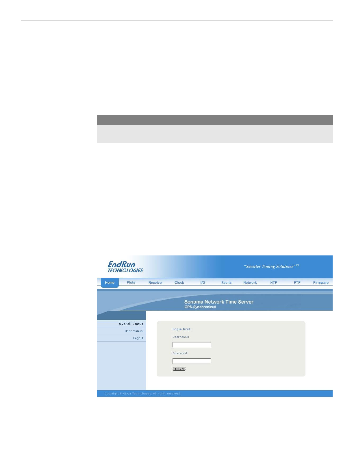
57
S o n o m a U s e r M a n u a l
H T T P S I N T E R FA C E
HTTPS Interface Description
C H A P T E R S E V E N
For security reasons the web pages on the Sonoma show status and conguration information only.
You cannot change any operational settings, however you can perform upgrades to the Sonoma rmware, which is done with several security measures in place. To make other changes to the Sonoma
you will need to use the command line interfact via either a network or serial port.
NOTE
For proper operation, your web browser must be configured to allow pop-up windows.
To get started with the web interface simply point your browser to the IP address of the Sonoma and
log in securely with HTTPS. Following are examples for IPv4 and IPv6:
IPv4: http://192.168.1.1
IPv6: http://[fe80:0:0:0:20e:f3ff:fe01:1f] Do not forget the brackets [].
A warning dialog page will be presented for the certicate. Acknowledge the dialog page and the
server will continue to load, protected by SSL. The browser should change from http: to https:, indicating that the page is protected by SSL. To maximize security you should replace the SSL Certicate. See Chapter 5 - Security, HTTPS for details.
Below is a picture of the login page:
56
S o n o m a U s e r M a n u a l
Page 73
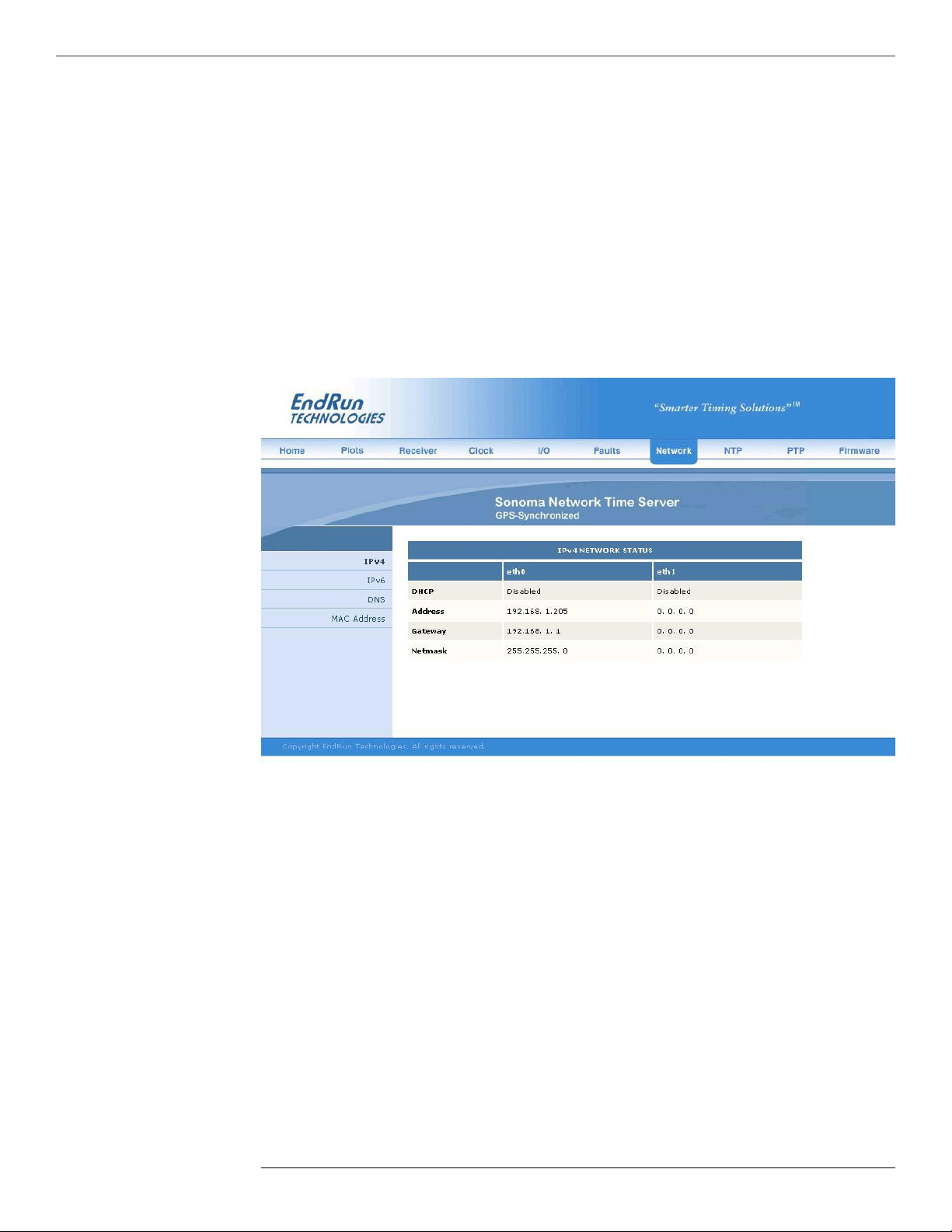
H T T P S I N T E R FA C E
Navigation
The main menu tabs across the top of each webpage allow you to navigate through the status information in the Sonoma while links on the left side of each webpage provide subcategory navigation.
For example, in the page below the main menu tabs are: Home, Receiver, Plots, Clock, I/O, Faults,
Network, NTP, PTP and Firmware. The subcategory links on this particular page are: IPv4, IPv6,
DNS and MAC Address. IPv4 is selected. The tabs across the top and the left-side links are logically
arranged for easy navigation.
57
S o n o m a U s e r M a n u a l
Page 74

59
S o n o m a U s e r M a n u a l
H T T P S I N T E R FA C E
Page Descriptions
C H A P T E R S E V E N
Home: Overall Status Page
Data elds for this page are described below.
Overall Status
Model Sonoma N12
Serial Number Serial number of the Sonoma N12. This eld will not be shown for units
shipped before August 2015.
UTC Time, The current UTC date and time is shown. This date will show year 1980 if
UTC Date the time has not yet been acquired.
Receiver This is the locked status of the GPS Subsystem/Receiver as follows:
WRM: Warmup period for units with oscillator upgrades.
ACQ: Acquring. Searching for a signal.
LKG: Locking to the GPS signal.
LKD: Locked. Fully synchronized to signal.
Stratum The NTP stratum eld has these possible values:
Stratum 1: The server is fully synchronized and accurate.
Stratum 2: The server is synchronized to a Stratum 1 server.
Stratum x: The server is synchronized to a Stratum x-1 server.
Stratum 16: The server is unsynchronized. NTP clients will not use a
Stratum 16 server.
System Status This eld indicates whether a system fault exists. Possible values are OK and
FAULT. If it shows FAULT then go to the Faults Page to see which particular
fault is the problem.
CPU Statistics
Current CPU temperature, CPU free memory and CPU load average are all shown.
Home: User Manual
This link provides access to the Sonoma User Manual that is resident in the FLASH memory. The
most recent version of the User Manual is on the EndRun website at:
http://www.endruntechnologies.com/pdf/USM3029-0000-000.pdf
Home: Logout
Clicking on this link will immediately log you out of the Sonoma HTTPS Interface.
58
S o n o m a U s e r M a n u a l
Page 75
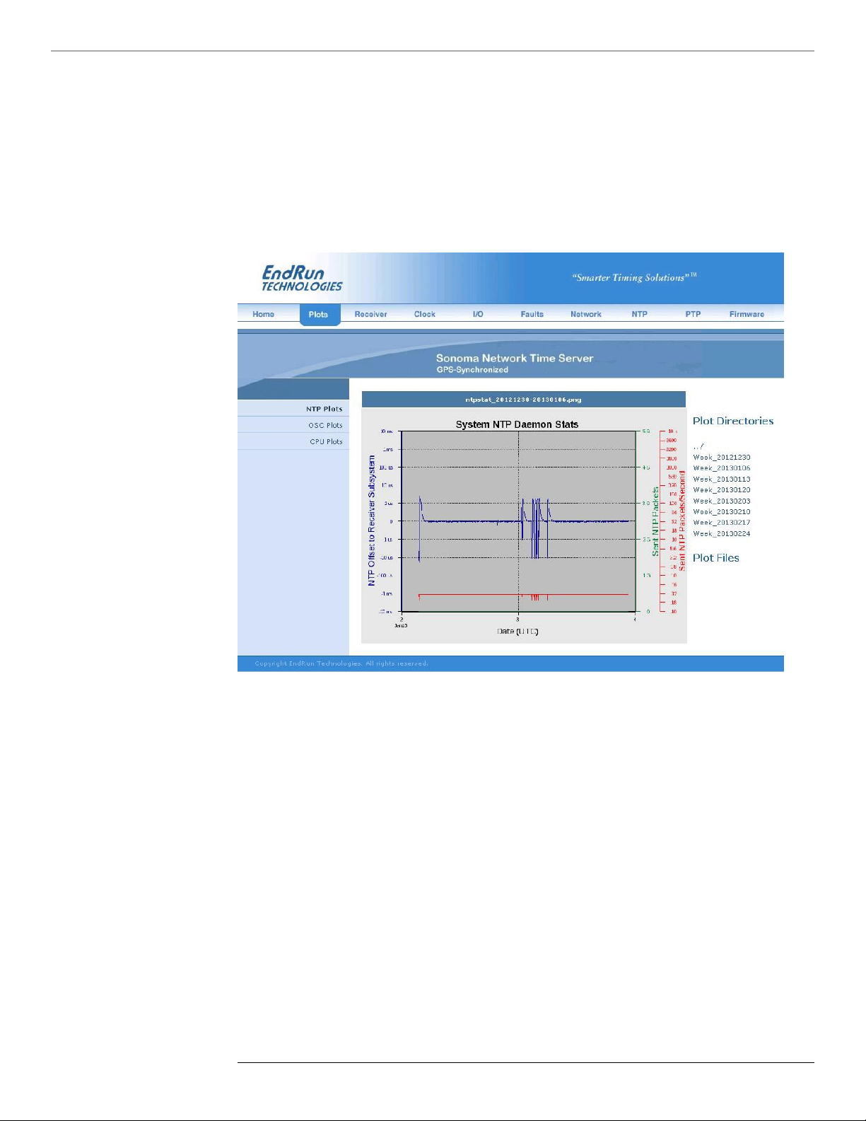
H T T P S I N T E R FA C E
Plots Page
Information available on this page are performance statistics related to NTP. Links on the right give
access to the daily plot les - going back up to 10 years. Links on the left give access to performance
statistics for CPU and Oscillator. A sample data plot is shown below:
There are three types of data plots available for viewing: CPU, NTP, Oscillator and Receiver (for
units shipped after May 2017, with the EndRun GPS Receiver). The large data plot shown on any of
the plot pages is the last data plot viewed. This could be from any one of the three data types (CPU,
NTP, Oscillator or Receiver).
All plot les are kept in directories. There is one directory for each week. To choose a new plot to
view, use the selections on the right side of the page. First, click to select a directory. Then you can
either click to select one of the listed plot les, or you can use your mouse to hover over one of the
plot les. Hovering over a plot le will display a small plot next to the large main plot. In this way
you can compare plots from different types to correlate data. For example, you can compare an NTP
data plot with a CPU data plot.
Plots les can also be downloaded from the Sonoma as .PNG les. They can be found in the directory /logs/png.
59
S o n o m a U s e r M a n u a l
Page 76

C H A P T E R S E V E N
61
S o n o m a U s e r M a n u a l
H T T P S I N T E R FA C E
Receiver: Receiver Page
This page contains information related to the GPS Subsystem/Receiver. Data elds are described
below. For units shipped after May 2017, with the EndRun GPS Receiver, there will be additional
elds.
GPS Receiver Status
State Shows the current state of the GPS Subsystem/Receiver:
WRM: Warmup period for units with oscillator upgrades.
ACQ: Acquring. Searching for a signal.
LKG: Locking to the GPS signal.
LKD: Locked. Fully synchronized to signal.
TFOM Shows the current TFOM value. See Appendix A - TFOM for more
information.
Satellite ID This eld lists the satellites that are currently being tracked. Up to 12 may be
tracked at a time. Click on the Satellite-Info link for details.
Average C/No The carrier-to-noise ratio is an indicator of the GPS signal quality.
This number typically ranges from 30 to 45 dB when the Sonoma is locked.
GPS Dynamic This eld shows whether the dynamic mode is set or not. Dynamic mode should
Mode be OFF when the Sonoma is in a static (not moving) position. To change the
dynamic mode setting use the gpsdynmode command.
WGS-84 Reference Position
Position Source The source of the reference position can be:
UNK: Unknown position.
DYN: Dynamic. Position determined while in Dynamic Mode.
USR: User-entered reference position.
AVG: Average is a 24-hour average of GPS xes.
To change the reference position source use the gpsrefpos command.
Latitute, The WGS-84 latitude and longitude in degrees, minutes and seconds format,
Longitude, and the height above the WGS-84 reference ellipsoid in meters is shown.
Height Refer to Appendix D - Installing the GPS Antenna, About WGS-84.
WGS-84 Last Position Fix
Latitude, These elds show information for the most recent position x. The WGS-84
Longitude, latitude and longitude in degrees, minutes, seconds format and the height above
Height the WGS-84 reference ellipsoid in meters is shown. Refer to Appendix D Installing the GPS Antenna, About WGS-84.
GPS-UTC Almanac Info
These elds show the ICD-GPS-200 almanac parameters which are used to relate GPS time to UTC.
LS, LSF These elds contain the current leap second and future leap second values.
S o n o m a U s e r M a n u a l
60
Page 77

H T T P S I N T E R FA C E
WNLSF, DN These elds show the GPS week number and day number of week at the end of
which the future leap second will take effect. This could be in the past if a leap
second insertion has recently taken place. Leap second events occur every few
years on either June 30 or December 31.
A0, A1, These elds show the parameters for calculating the small residual offset
WNt, tot between the GPS master clock ensemble and UTC-USNO. This is typically
less than 10 nanoseconds.
Current This is the current value of the GPS-UTC offset, which includes leap seconds
(GPS-UTC) plus the small residual offset explained above. Time and date of most recently
received satellite transmission containing this data is also shown.
Conguration
Clock Calibration Clock calibration is used to advance or retard the clock in order to correct for
GPS Receiver delay and any propagation delay due to GPS antenna cable.
It may also be used to compensate for the inherent time offsets that may exist
with external hardware such as distribution ampliers, etc. Calibration range is
±500,000 nanoseconds.
Receiver: Oscillator Page
This page shows system oscillator control information such as:
Oscillator Status
Oscillator Type This eld shows the system oscillator type that is installed in the Sonoma. It
will be either TCXO (standard), OCXO (option) or Rubidium (option).
DAC The system oscillator control DAC value indicates the frequency control setting.
The system automatically sets this value to remove frequency errors. Values
may range from 0 to 1,048,575. Values close to the minimum or maximum will
set the DAC fault ag.
Measured This eld shows the last measured time offset of the GPS Subsystem relative to
Time Error GPS while locked, in second.
Time Deviation This eld shows the time deviation (TDEV) of the offset measurements in
seconds. The tau associated with this measurement is one second, which is the
update interval of the position xes received from the GPS Receiver.
Oscillator This eld shows the regression-computed system oscillator ageing rate per day
Ageing Rate (several-hours delay before the rst measurements are displayed).
Control Loop TAU This eld shows the system oscillator control loop averaging time constant, in
seconds. It’s value is automatically adjusted to maintain optimum offset and
stability.
61
S o n o m a U s e r M a n u a l
Page 78

C H A P T E R S E V E N
63
S o n o m a U s e r M a n u a l
H T T P S I N T E R FA C E
Coast Duration This shows the number of seconds the GPS Subsystem has been in coast mode,
while the Sonoma is unlocked to GPS. Coast mode is another term for holdover
mode.
Estimated Time This is the estimated time error of the GPS Subsystem when in coast/holdover
Error mode, in seconds.
Internal Chassis Internal chassis temperature in °C. Available with OCXO or Rubidium
Temperature oscillator.
Clock Page
This page shows the conguration of the Sonoma Time Server except for any optional I/O which is
listed on the I/O page.
Clock Conguration
Time Mode This eld shows the current time mode setting. Possible settings are UTC, GPS
and Local. Since NTP always uses UTC, this setting only affects any optional
Time Code or Serial Time outputs. To change the time mode setting
use the systimemodeconfig command via the console port.
Time Zone This eld shows the offset from UTC and is only valid when the Time Mode is
Offset Local. A positive Time Zone Offset implies a longitude east of the Greenwich
meridian. To change the time zone use the systimemodeconfig command.
Daylight Savings This eld will show whether DST control is enabled or not.
Time DST elds are only used when the Time Mode is Local.
DST Start, These elds will only display if the Daylight Savings Time eld above shows
DST End enabled. If enabled, then these elds show when DST starts and ends during the
year. For example, in most of the U.S.A. the DST Start Time is the 2nd Sunday
in March at 2 a.m. The DST End Time is the 1st Sunday in November at 2
a.m. DST settings are used when the time mode is Local. To change the DST
settings use the systimemodeconfig command.
I/O Page
This page shows any installed CPU Options and their settings. These are optional outputs that are
generated from the CPU Module in the Sonoma. A basic Sonoma Time Server has no CPU Options
installed. Use commands cpuioconfig and sysioconfig via the console port to change the settings of the CPU Options. See Chapter 10 - Options for information on the various options.
Faults: System Faults Page
This page lists all possible fault conditions of the Sonoma. For details on each fault see Appendix G
- System Faults.
62
S o n o m a U s e r M a n u a l
Page 79

H T T P S I N T E R FA C E
Faults: Fault Mask Page
This page shows the fault masks available.
Fault Masks
Signal Fault This eld shows the current mask setting for the Signal Fault, either Masked or
Enabled. When the signal fault is Masked it will prevent a Signal Loss Fault
from occurring. Some installations may need to mask this fault when operating
the Sonoma with no GPS signal. (An example of this would be when
congured as a Stratum 2 NTP Server.) To change the Signal Fault Mask use
the setsigfltmask command.
Antenna Fault This eld shows the current mask setting for the Antenna Fault. When the
antenna fault is Masked it will prevent an Antenna Fault from occurring.
Some installations may need to mask this fault due to special antenna situations
like splitters. To change the Antenna Fault Mask use the setantfltmask
command.
Primary and These elds will display ONLY if your Sonoma has the Dual Power Supply
Secondary Power option installed. See Chapter 10 - Options, Masking Dual Power Supply
Fault Alarms Fault Alarms for more information.
Network: IPv4 Page
This page shows the IPv4 network conguration.
IPv4 Network Status
DHCP By default, the Sonoma will congure itself using the Dynamic Host
Conguration Protocol (DHCP). If you need to set up static IP conguration,
you must use the netconfig command via the console port. Thie eld will
show whether DHCP is enabled or disabled.
Address, Gateway These elds show the settings for the IP address, gateway and netmask.
Netmask To change these settings use the netconfig command via the console port.
Network: IPv6 Page
This page shows information related to the IPv6 network parameters. For more information on IPv6
see Chapter 8 - IPv6 Information.
Network: DNS Page
This page shows the IP addresses of the primary and secondary domain name servers.
Network: MAC Address Page
This page shows the media-access-control (MAC) address for both ethernet ports (eth0 and eth1).
63
S o n o m a U s e r M a n u a l
Page 80

C H A P T E R S E V E N
65
S o n o m a U s e r M a n u a l
H T T P S I N T E R FA C E
NTP Page
The NTP Status page shows all information related to NTP operation.
NTP Status
Status The stratum eld has several possible values:
Stratum 1: The server is fully synchronized and accurate.
Stratum 2: The server is synchronized to a Stratum 1 server.
Stratum x: The server is synchronized to a Stratum x-1 server.
Stratum 16: The server is unsynchronized. NTP clients will not use a
Stratum 16 server.
Source This eld will show the source of time which is usually GPS. If the Sonoma is
congured as a Stratum 2 server then it will show the IP address of the
upstream Stratum 1 server.
Offset This eld shows the offset in seconds between the NTP system clock and the
GPS Subsystem clock. Positive implies that the NTP system clock is ahead of
the GPS Subsystem clock.
Leap Indicator This eld shows whether a leap second is pending.
Bits Leap seconds occur about every 1 to 3 years. Possible indicator values are:
00: Normal, locked operation.
01: Leap second insertion will occur after 23:59:59 UTC.
10: Leap second deletion will occur after 23:59:58 UTC.
11: Fault. Unsynchronized state.
I/O Statistics
Time Since Reset, These elds show statistics accumulated since the last reboot of the system.
Packets Sent/Received,
Packets Sent Rate,
Packets Dropped
PTP: Status and Configuration Pages
The elds on these pages show the status and the conguration for the optional PTP/IEEE-1588 protocol. If your Sonoma does not have PTP enabled then there will be no elds shown. For more information on PTP and an explanation of the data elds on this page see Chapter 4 - PTP/IEEE-1588.
Firmware: Firmware Status Page
The rmware status page shows part numbers and revisions for Sonoma rmware.
Firmware Status
Linux RFS PN, These elds show the Linux root le system part number, version & date.
Linux RFS Version
Linux Kernel PN, These elds show the Linux kernel part number, version & date.
Linux Kernel Version
S o n o m a U s e r M a n u a l
64
Page 81

H T T P S I N T E R FA C E
GPS Subsystem This eld shows the GPS Subsystem rmware version.
Firmware
GPS Subsystem This eld shows the GPS Subsystem Field Programmable Gate Array (FPGA)
FPGA version.
Firmware: Linux RFS Upgrade Page
This page is used for upgrading the Linux RFS rmware. You must be logged in as “root” in order to
have access to this page. The latest released versions of Sonoma rmware are freely available on the
EndRun Technologies website. For detailed information on how to perform the upgrade either via the
network port, the serial port, or the HTTPS interface see Appendix B - Upgrading The Firmware.
Firmware: Linux Kernel Upgrade
This page is used for upgrading the Linux kernel rmware. You must be logged in as “root” in order
to have access to this page. The latest released versions of Sonoma rmware are freely available on
the EndRun Technologies website. For detailed information on how to perform the upgrade either via
the network port, the serial port, or the HTTPS interface see Appendix B - Upgrading The Firm-
ware.
Disable or Restrict Access
Firmware: GPS Subsystem Upgrade Page
This page is used for upgrading the rmware. You must be logged in as “root” in order to have
access to these pages. The latest released versions of Sonoma rmware are freely available on the
EndRun Technologies website. For detailed information on how to perform the upgrade either via the
network port, the serial port, or the HTTPS interface see Appendix B - Upgrading The Firmware.
Firmware: Reboot Page
This page will allow you to perform a software reboot of both the Linux Subsystem and the GPS
Subsystem. This is normally used after a rmware upgrade but can be done anytime you wish to
reset the Sonoma.
To disable HTTPS, see Chapter 5 - Security, Disable SNMP, SSH and HTTPS. To restrict access to
specic hosts see Chapter 5 - Security, Restrict Access - HTTPS.
65
S o n o m a U s e r M a n u a l
Page 82

C H A P T E R S E V E N
This page intentionally left blank.
66
S o n o m a U s e r M a n u a l
Page 83

"Smarter Timing Solutions"
IPv6 Capabilities
Chapter
Eight
IPv6
The Sonoma Time Servers support IPv6 out-of-the-box with a modern version 3.2.2 Linux kernel.
During network conguration, you have the option to disable IPv6 on either or both Ethernet ports.
The IPv6 addressing scheme will see expanding deployment in the near future due to the fact that
there are no longer any IPV4 addresses to be allocated in many regions of the world.
The presence of an IPv6-capable kernel will automatically enable most of the IPv6 capabilities. By
default, autoconguration of the Ethernet interfaces via IPv6 Router Advertisements is enabled. To
disable acceptance of Router Advertisements, or to congure a static IPv6 address and default IPv6
gateway, and to congure IPv6 domain name servers, you must run the interactive netconfig script.
Either method will allow you to congure your Ethernet interface for both IPv4 and IPv6 operation.
Using the netconfig script has the advantage that you can also congure the hostname and domainname for the unit.
OpenSSH
By default, sshd is factory-congured to listen on both IPv4 and IPv6 addresses. It may be forced to
listen on either IPv4 only, or IPv6 only by editing the /etc/ssh/sshd_config le and modifying the Ad-
dressFamily directive, and then copying it to /boot/etc/ssh. Refer to the sshd_config man page for
detailed information (man sshd_config).
Apache HTTP
By default, httpd is factory-congured to listen on both IPv4 and IPv6 addresses. It may be forced
to listen on either IPv4 only, or IPv6 only by editing the /etc/httpd/httpd.conf conguration le and
adding a Listen directive, and then copying it to /boot/etc/httpd. Refer to the Apache HTTP documentation for details.
Net-SNMP
By default, snmpd is factory-congured to listen on both IPv4 and IPv6 addresses. This may be
changed by editing /etc/rc.d/rc.snmpd and modifying the agent address argument passed to snmpd at
start-up, and then copying it to /boot/etc/rc.d.
67
S o n o m a U s e r M a n u a l
Page 84

C H A P T E R E I G H T
NTP
By default, ntpd is factory-congured to listen on both IPv4 and IPv6 addresses on all interfaces.
This may be changed by editing /etc/ntp.conf and adding the desired interface directives to
achieve the desired behavior, and then copying it to /boot/etc. For example, adding this line:
interface ignore ipv6
will cause ntpd to not bind to any IPv6 addresses. Refer to the NTP documentation for details on the
interface directive.
IPv4-Only Protocols
There are several protocols running on the Sonoma which are not IPv6 capable: telnet (client and
server), ftp and dhcpcd. Due to their intrinsic insecurity, telnet and ftp are rapidly being deprecated, and probably have little business running over an IPv6 network. The address autoconguration
capabilities of IPv6 along with the Neighbor Discovery Protocol (NDP) make the DHCP protocol less
important in IPv6 networks. The optional PTP/IEEE-1588 protocol is also not available on IPv6.
68
S o n o m a U s e r M a n u a l
Page 85

"Smarter Timing Solutions"
Console Ports
General Linux Operation
Chapter
Nine
Console Port Control and Status
This chapter describes the Sonoma control and status commands used via the Linux console. The
console is accessed via any of the ethernet ports or the RS-232 serial port. The Sonoma supports several application-specic commands for conguration and for monitoring the performance and status
of the Linux and GPS Subsystems.
You do not need knowledge of Linux commands in order to operate the Sonoma. However, the Sonoma does support a subset of the standard Linux commands and utilities and it uses the bash shell,
which is the Linux standard, full-featured shell. A wealth of information is available from a variety of
other sources on Linux.
The Sonoma-specic commands will be described in this chapter. For a brief description of some of
the most useful Unix/Linux commands, see Appendix C - Helpful Linux Information.
Three interface ports are available on the Sonoma N12. Two are 10/100/1000Base-T ethernet ports
and one is an RS-232 serial port. Network cables and a serial cable are provided with each Sonoma
shipment. The serial cable is wired as a null-modem adapter and can be used to connect the Sonoma
to the serial port on your computer. Detailed specications on the ports, including the RS-232 pinout,
are in Appendix H - Specifications.
You do not need to know Linux in order to operate the Sonoma. However, for those interested, the
command shell used by the Sonoma is the Linux standard: bash. All commands and le names are
case sensitive, which is standard for Unix-like operating systems. For a brief description of some of
the most useful Unix/Linux commands, see Appendix C - Helpful Linux Information.
If you are unfamiliar with Unix-like operating systems, and you would like to be able to more closely
monitor or optimize the performance of your Sonoma then you should consult good Linux reference
books or the Linux Documentation Project at::
http://www.tldp.org
69
S o n o m a U s e r M a n u a l
Page 86

71
S o n o m a U s e r M a n u a l
C O N T R O L A N D S TA T U S C O M M A N D S
Available User Commands
C H A P T E R N I N E
COMMAND FUNCTION
accesscong Interactive script that guides you in conguring
telnet, ssh and snmpd access to the Sonoma that is limited
to specic hosts. The resulting /etc/hosts.allow and
/etc/hosts.deny les are saved to the non-volatile FLASH disk.
Factory default conguration allows access by all hosts.
anttmask Prints the current setting for the Antenna Fault Mask.
See the setantfltmask command.
caldelay Prints the calibration delay. See the setcaldelay command.
cpuio
(optional)
Returns the current settings for any installed, user-selectable,
CPU Module options. See Chapter 10 - Options, CPU Module
Options for more information.
cpuiocong
(optional)
An interactive utility that allows you to modify the settings
for the CPU Module options. See Chapter 10 - Options, CPU
Module Options for more information.
cpustat Prints the current Linux CPU core temperature, system load as
percent of maximum and free memory available.
faultstat Prints the summary of all system fault states in a user-friendly
format.
get_sw_opts Returns the current software options enabled in your Sonoma.
See Chapter 10 - Options, Software Options for more information.
gpsdynmode Prints the GPS dynamic mode currently in effect.
See the setgpsdynmode command.
gpslastx Prints the last computed GPS position x.
gpsrefpos Prints the GPS reference position.
See the setgpsrefpos command.
gpsstat Prints the GPS Subsystem status information.
gpstrkstat Prints the GPS satellite tracking status. Azimuth, elevation and
signal level (C/No) are shown for each satellite.
gpsutcinfo Prints the GPS UTC Almanac parameters per the GPS-ICD-
200. Also shows the current calculated GPS-UTC offset, which
includes leap seconds and a small sub-second offset.
gpsversion Prints the GPS Subsystem rmware and FPGA version infor-
mation.
help
help command
Prints help for all Sonoma-specic (not Linux) commands.
Prints command-specic help. For example: help gpsstat.
inetdcong Interactive script that allows you to congure the list of pro-
tocol servers which are started by the inetd server daemon
running in the Sonoma.
kernelversion Prints the Linux operating system kernel version.
netcong Interactive script that allows you to congure the IP network
subsystem of the Sonoma.
70
S o n o m a U s e r M a n u a l
Page 87

C O N T R O L A N D S TA T U S C O M M A N D S
ntpcong Interactive script that guides you in conguring the NTP
Subsystem. Allows conguration of MD5 authentication and
broadcast/multicast mode. All parameters are retained in nonvolatile FLASH disk storage.
ntpstat Prints the values of several key parameters indicating the status
of the NTP daemon. These include the current offset between
the NTP-steered system clock and the GPS Subsystem clock,
and the current counts of received packets, sent packets and
dropped packets. In addition the current sent packet rate is
shown.
oscctrlstat Prints the system oscillator disciplining parameters.
passwd Used to change the password for the user that you are logged
in as.
ptpcong0
ptpcong1
(optional)
ptpstat0
ptpstat1
Interactive script that guides you in conguring parameters for
the optional PTP/IEEE-1588 protocol. See Chapter 4 - PTP/
IEEE-1588 for more information.
Prints the status of the optional PTP/IEEE-1588 Subsystem.
See Chapter 4 - PTP/IEEE-1588 for more information.
(optional)
pwrtmask
(optional)
Prints the current settings of the optional Dual Power Supply
Input Fault Alarm Masks. See Chapter 10 - Options, Masking
Dual Power Supply Fault Alarms for more information.
rcvrserialnumber
Prints the serial number of the GPS Receiver. This command is
not available in units shipped before June 2017.
rcvrstat
Prints the status of the GPS Receiver. This command is not
available in units shipped before June 2017.
rcvrversion Prints the GPS Receiver rmware and FPGA version informa-
tion. This command is not available in units shipped before
June 2017.
resetlastgpswn
For use with a GPS simulator. This command is not available in
units shipped before June 2017.
resetleaphistory
For use with a GPS simulator. This command is not available in
units shipped before June 2017.
rcvrserialnumber
Prints the serial number of the GPS Receiver. This command is
not available in units shipped before June 2017.
rcvrstat
Prints the status of the GPS Receiver. This command is not
available in units shipped before June 2017.
rcvrversion Prints the GPS Receiver rmware and FPGA version informa-
tion. This command is not available in units shipped before
June 2017.
resetlastgpswn
For use with a GPS simulator. This command is not available in
units shipped before June 2017.
resetleaphistory
For use with a GPS simulator. This command is not available in
units shipped before June 2017.
71
S o n o m a U s e r M a n u a l
Page 88

C H A P T E R N I N E
73
S o n o m a U s e r M a n u a l
C O N T R O L A N D S TA T U S C O M M A N D S
serialnumber
Prints the serial number of the Sonoma. The serial number
is not available using this command in units shipped before
August 2015.
setanttmask Command to enable or mask the Antenna Fault.
See the antfltmask command.
setcaldelay An interactive utility that allows you to change the clock cali-
bration delay. See the caldelay command.
setgpsdynmode Command to set the dynamic mode of operation of the GPS
Subsystem. See the gpsdynmode command.
setgpsrefpos Interactive utility that prompts you for an accurate reference
position, performs syntax and argument validity checking then
passes the position to the GPS Subsystem.
See the gpsrefpos command.
setpwrtmask
(optional)
Command to enable or mask the optional Dual Power Supply
Input Faults. See Chapter 10 - Options, Masking Dual Power
Supply Fault Alarms for more information.
setsigtmask Command to enable or mask the Signal Loss Fault.
See the sigfltmask command.
sigtmask Prints the current setting for the Signal Loss Fault mask.
See the setsigfltmask command.
subsysreset Command that performs a GPS Subsystem reset.
syskernel Prints the currently booted Linux kernel, either 0 or 1, where 0
is the factory-installed kernel and 1 is the upgraded kernel.
sysosctype Prints the installed system oscillator type, which is one of
TCXO, OCXO or Rubidium.
sysrootfs Prints the currently loaded Linux root le system image, either
0 or 1, where 0 is the factory-installed root le system, and 1 is
the upgraded root le system.
sysstat Prints detailed NTP status information. Included is the offset
of the NTP-steered system clock to the GPS Subsystem clock,
the NTP daemon leap indicator bit values, the TFOM, the time
of the most recent update and the current leap seconds value.
systemio
(optional)
Returns the current settings for any installed, system options.
See Chapter 10 - Options, CPU Module Options for more
information.
systemiocong
(optional)
An interactive utility that allows you to modify the settings for
the system options. See Chapter 10 - Options, CPU Module
Options for more information.
systimemode Prints the time mode settings in effect for the any optional Time
Code or Serial Time output.
See the systimemodeconfig command.
systimemodecong Interactive utility that guides you in conguring the time mode
settings for any optional Time Code or Serial Time output.
Allows setting to the LOCAL, GPS or UTC timescale. See the
systimemode command.
sysversion Prints the Linux root le system version information.
72
S o n o m a U s e r M a n u a l
Page 89

C O N T R O L A N D S TA T U S C O M M A N D S
updatekernelag Command to update the ag stored in FLASH that is read by
the Linux bootloader at boot time to select operation with either
the factory-installed or upgraded kernel.
updaterootag Command to update the ag stored in FLASH that is read by
the Linux bootloader at boot time to select operation with either
the factory-installed or upgraded root le system.
upgradekernel Command that performs the Linux kernel upgrade process.
upgradercvr Command that performs the GPS Receiver upgrade process.
This command is not available in units shipped before June
2017.
upgradercvrfpga Command that upgrades the FPGA resident on the GPS Re-
ceiver. This command is not available in units shipped before
June 2017.
upgradercvr Command that performs the GPS Receiver upgrade process.
This command is not available in units shipped before June
2017.
upgradercvrfpga Command that upgrades the FPGA resident on the GPS Re-
ceiver. This command is not available in units shipped before
June 2017.
upgraderootfs Command that performs the Linux root le system upgrade
process.
upgradesubsys Command that performs the GPS Subsystem rmware upgrade
process.
wrt_sw_opt Command to enable a software option. See Chapter 10 - Op-
tions, Software Options for information.
Detailed Command Descriptions
accessconfig
This command starts an interactive script that will allow the root user to congure access limitation
via telnet, ssh and snmp to the Sonoma. By default, the unit is congured to allow access by all
users. If you need to limit telnet, ssh or snmp access, e.g. for security reasons, you must run this
script as root from either the RS-232 serial I/O port or from a telnet or ssh session.
This script modies these les: /etc/hosts.allow and /etc/hosts.deny. These are non-volatilely stored
in the FLASH disk /boot/etc directory. You must reboot the Sonoma after running this script for the
changes to take effect.
Command: accessconfig
Sonoma reply: Interactive script is started.
73
S o n o m a U s e r M a n u a l
Page 90

C H A P T E R N I N E
75
S o n o m a U s e r M a n u a l
C O N T R O L A N D S TA T U S C O M M A N D S
antfltmask
This command displays the current setting for the Antenna Fault Mask.
Command: antfltmask
Sonoma reply: Antenna Fault is ENABLED
caldelay
This command displays the current calibration delay setting. The allowable calibration delay range is
±500,000 nanoseconds.
Command: caldelay
Sonoma reply: +0 nanoseconds
cpuio (Optional)
See Chapter 10 - Options, CPU Module Options for information on this command.
cpuioconfig (Optional)
See Chapter 10 - Options, CPU Module Options for information on this command.
cpustat
This command shows a group of key values for monitoring the health of the Linux CPU and operating system status. The format is:
YYYYMMDD.HH:MM:SS LLL% FREEkB +TT.TC
Where:
YYYY is the year of the UTC timestamp of the most recent update.
MMDD is the month and day-of-month of the UTC timestamp of the most recent update.
HH:MM:SS is the hour, minute and second of the UTC timestamp of the most recent update.
LLL% is the percentage of maximum load as returned using the Linux vmstat command.
FREEkB is the available free memory in kilobytes as returned using the Linux vmstat command.
+TT.TC is the temperature in degrees centigrade of the Linux CPU die temperature.
Command: cpustat
Sonoma reply: 20170116.22:24:00 23% 320056kB +67.9C
74
S o n o m a U s e r M a n u a l
Page 91

C O N T R O L A N D S TA T U S C O M M A N D S
faultstat
This command returns the summary of all system fault states in a user-friendly format. It decodes the
fault status word (FLTS) returned in the gpsstat command and displays the result in a tabular form
with verbose descriptions. (For units shipped after May 2017 there will be additional faults for the
GPS Receiver.) For details on the various faults see Appendix G - System Faults.
Command: faultstat
Sonoma reply: System Fault Status:
System Oscillator DAC -------------------------> OK
GPS Signal ------------------------------------> OK
FPGA Configuration ----------------------------> OK
FLASH Writes ----------------------------------> OK
GPS Receiver Communication --------------------> OK
GPS Reference Time ----------------------------> OK
Subsystem Communication -----------------------> OK
GPS Antenna -----------------------------------> OK
System Oscillator PLL Unlocked-----------------> OK
System Power/Configuration --------------------> OK
get_sw_opts
See Chapter 10 - Options, Software Options for information on this command.
gpsdynmode
This command displays the current GPS Subsystem dynamic mode of operation. It has two possible
settings: ON or OFF. When it is ON, it is assumed that the Sonoma is installed on a moving platform. When it is OFF, it is assumed that the Sonoma is installed in a stationary location.
When the dynamic mode is OFF, the Sonoma will use its accurate reference position to implement
Timing Receiver Autonomous Integrity Monitoring (TRAIM) for the utmost in reliability during any
GPS system faults. In addition, single satellite operation is possible once an initial accurate position
has been determined.
When the dynamic mode is ON, only a very minimal TRAIM algorithm is in effect because the accurate reference position is not static. In addition, a minimum of four satellites must be visible and
only 3-D position xes are used. When the dynamic mode is ON, the source reported for the accurate
reference position by gpsrefpos is set to DYN.
Command: gpsdynmode
Sonoma reply: OFF
gpslastfix
This command provides the last computed GPS position. When tracking four or more satellites, the
GPS Receiver provides a 3D-position x. When only three satellites are in view, this will drop to
a 2D-position x. The last-x position is unaveraged and typically less accurate than the reference
position, but it does provide a good indication that the receiver is working properly. Position is provided in latitude, longitude and height above the WGS-84 ellipsoid.
Command: gpslastfix
Sonoma reply: LAST POSITION FIX = N38d24m54.28s W122d45m10.89s +00010.9 meters
75
S o n o m a U s e r M a n u a l
Page 92

C H A P T E R N I N E
77
S o n o m a U s e r M a n u a l
C O N T R O L A N D S TA T U S C O M M A N D S
gpsrefpos
This command displays the current GPS Subsystem reference position. The source of the position,
which is one of UNK (unknown), DYN (dynamic), USR (user entered) or AVG (24 hour average of
GPS xes) is displayed rst. The WGS-84 latitude and longitude in degrees, minutes, seconds format
and the height above the WGS-84 reference ellipsoid in meters follow.
Command: gpsrefpos
Sonoma reply:
CURRENT REFERENCE POSITION = AVG N38d26m36.11s W122d42m56.50s +00032.5 meters
gpsstat
This command allows you to query the status of the GPS Subsystem. During normal operation, the
NTP daemon polls the GPS Subsystem every 16 seconds. The results of this poll are used to steer the
system clock and are saved to a log le. This command parses and formats the data contained therein
and prints this xed-length string having these elds:
LKSTAT TFOM = ? YEAR DOY HH:MM:SS LS LF S NN EFCDAC C/No FLTS
or
LKSTAT TFOM = ? YEAR DOY HH:MM:SS LS LF S NN AGC EFCDAC C/No FLTR FLTS
Where:
LKSTAT is the tracking status of the GPS Subsystem, either LOCKED or NOTLKD.
TFOM = ? is a value between 3 and 9 and indicates clock accuracy.
A detailed explanation of TFOM is in Appendix A - TFOM.
YEAR is the year of the UTC timestamp of the most recent update.
DOY is the day-of-year of the UTC timestamp of the most recent update.
HH:MM:SS is the hour, minute and second of the UTC timestamp of the most recent update.
LS is the current number of leap seconds difference between the UTC and GPS timescales
(18 at the time of this writing).
LF is the future (at the next UTC midnight) number of leap seconds difference between the
UTC and GPS timescales (18 at the time of this writing).
S is the Signal Processor State, one of 0 (Acquiring), 1 (GPS Locking), 2 (GPS Locked), 9
(Warming Up).
NN is the number of GPS satellites being tracked, 0 to 12.
AGC is the current receiver Automatic Gain Control DAC word, 0 to 255. This eld is
not shown in units shipped before June 2017.
S o n o m a U s e r M a n u a l
76
Page 93

C O N T R O L A N D S TA T U S C O M M A N D S
EFCDAC is the system oscillator Electronic Frequency Control 20-bit DAC value, 0 to 1048575
with larger numbers implying higher oscillator frequency. Typical range is 320000 to
680000.
C/No is the received GPS Carrier Signal-to-Noise Ratio, 0.00 to 99.9, measured in dB in a 1Hz
bandwidth. Typical range is 30 to 45.
FLTR is the fault status for the GPS Receiver. (This eld is not shown in units shipped before
June 2017.) This is a numeric value consisting of four hexadecimal characters where
each bit indicates a particular fault. Assertion of any of these bits will light the Alarm
LED. Bit denitions are shown below. Decoding the bits can be difcult for non programmers. For a more user-friendly method of reading the fault status use the
faultstat command. For details on each receiver fault see Appendix G - System
Faults.
Bit 3 Bit 2 Bit 1 Bit 0
Char 0 FLASH Writes FPGA
Conguration
Char 1 GPS Receiver
Oscillator
GPS Reference
Time
Char 2 N/A GPS Receiver
Oscillator PLL
GPS Signal GPS Receiver
Oscillator DAC
Local Oscillator
Synthesizer
GPS Antenna
Open
Local Oscillator
Synthesizer Tuning
GPS Antenna
Short
Char 3 N/A N/A N/A N/A
FLTS is the fault status for the GPS Subsystem. This is a numeric value consisting
of four hexadecimal characters where each bit indicates a particular system fault.
Assertion of any of these bits will light the Alarm LED. Bit denitions are shown below.
Decoding the bits can be difcult for non-programmers. For a more user-friendly method
of reading the fault status use the faultstat command. For details on each system
fault see Appendix G - System Faults.
Bit 3 Bit 2 Bit 1 Bit 0
Char 0 FLASH Writes FPGA
Conguration
Char 1 GPS Antenna Subsystem
Communication
Char 2 N/A System Osc PLL Secondary Power
Char 3 System Power/
N/A N/A N/A
GPS Signal System Oscillator
DAC
GPS Reference
Time
GPS Receiver
Communication
Primary Power
Supply
Supply
Conguration
The Primary and Secondary Power Supply bits are only used if your Sonoma has the Dual-Redundant
Power Supply option.
The example reply below indicates that there has been a period without tracking a GPS signal that
exceeded the time-out period, that there was a FLASH Write Fault and that there is an Antenna Fault.
77
S o n o m a U s e r M a n u a l
Page 94

C H A P T E R N I N E
79
S o n o m a U s e r M a n u a l
C O N T R O L A N D S TA T U S C O M M A N D S
Command: gpsstat
Sonoma reply:
LOCKED TFOM = 4 2001 092 04:48:56 13 13 2 7 328605 41.6 008A
or
LOCKED TFOM = 4 2017 092 04:48:56 18 18 2 7 181 328605 41.6 0100 008A
gpstrkstat
This command displays the current GPS Subsystem satellite tracking status. A list of twelve satellite
numbers along with azimuth, elevation and C/No is displayed for each receiver channel. Satellite
number 0 is an invalid number and indicates that no satellite is being tracked on that channel. Valid
satellite numbers range from 1 to 32. Azimuth and elevation are in degrees and C/No is in dB.
Command: gpstrkstat
Sonoma reply: Ch SV Azimuth Elev C/No
1 23 -108.41 +15.70 41.7
2 11 -118.21 +45.58 46.9
3 22 +107.41 +21.04 37.9
4 14 +52.10 +29.76 40.4
5 32 -40.36 +58.18 45.2
6 1 -79.14 +55.53 46.6
7 31 +127.87 +62.60 47.3
8 0 +0.00 +0.00 0.0
9 0 +0.00 +0.00 0.0
10 0 +0.00 +0.00 0.0
11 0 +0.00 +0.00 0.0
12 0 +0.00 +0.00 0.0
gpsutcinfo
This command displays the ICD-GPS-200 almanac parameters which are used to relate GPS time to
UTC. The rst line of output contains the current (LS) and future (LSF) leap second values and the
GPS week number (WN_lsf) and day of week (DN) at the end of which the future leap second will
take effect. This could be in the past if a leap second insertion has recently taken place. Leap second
events occur every few years on either June 30 or December 31.
The second line of output contains the parameters for calculating the small residual offset between
the GPS master clock ensemble and UTC-USNO. This is typically less than 10 nanoseconds. The
remaining output shows the current value of the GPS-UTC offset.
Command: gpsutcinfo
Sonoma reply: GPS UTC Almanac Parameters:
LS = 16 LSF = 16 WN_lsf = 1694 DN = 7
a0 = +9.313226e-10 a1 = -1.243450e-14 WN_t = 1727 t_ot = 61440
Current (GPS - UTC) Offset:
GPS - UTC = (16 + 3.810e-09) s @ WN = 1726, TOW = 434757
78
S o n o m a U s e r M a n u a l
Page 95

C O N T R O L A N D S TA T U S C O M M A N D S
gpsversion
This command displays the rmware and hardware versions of the GPS Subsystem.
Command: gpsversion
Sonoma reply:
F/W 6010-0071-000 Ver 1.00 - FPGA 6020-0012-000 Ver 01 - JAN 15 17:03:27 2013
help
This command displays a list of the Sonoma commands (not Linux commands). To get help on a
particular command you would type help, followed by the command.
Command: help
Sonoma reply: Sonoma commands are displayed.
Command: help gpsstat
Sonoma reply: Information specic to the gpsstat command is displayed.
inetdconfig
This command starts an interactive script that allows you to congure the list of protocol servers
which are started by the inetd super-server daemon running in the Sonoma. Three protocol servers
may be congured: Time, Daytime, and Telnet. By default, the unit is congured to start all of these
protocol servers. If you need to disable start-up of some or all of these, e.g. for security reasons, you
must run this script as root from either the RS-232 serial I/O port or from a telnet or ssh session.
This script modies the /etc/inetd.conf le, which is non-volatilely stored in the FLASH disk /boot/
etc directory. You must reboot the Sonoma after running this script for the changes to take effect.
Command: inetdconfig
Sonoma reply: Interactive script is started.
kernelversion
This command prints the current Linux operating system kernel rmware version.
Command: kernelversion
Sonoma reply:
6010-0064-000_v1.00 Linux Kernel 3.2.2-Sonoma #2 Dec 19 01:08:43 2012
netconfig
This command starts an interactive script that allows you to congure the IP network subsystem of
the Sonoma. By default, the unit is congured to congure itself using the Dynamic Host Conguration Protocol (DHCP). If you need to set up static IP conguration, you must run this script as root
from the RS-232 serial I/O port during the installation process. Refer to Chapter 2 - Basic Installa-
tion, Using netconfig to Set Up Your IP for details on the use of the command.
79
S o n o m a U s e r M a n u a l
Page 96

C H A P T E R N I N E
81
S o n o m a U s e r M a n u a l
C O N T R O L A N D S TA T U S C O M M A N D S
This script creates or modies these les: /etc/HOSTNAME, /etc/hosts, /etc/networks, /etc/resolv.conf
and /etc/rc.d/rc.inet1.conf. All of these are non-volatilely stored in the FLASH disk /boot/etc direc-
tory. You must reboot the Sonoma after running this script for the changes to take effect.
Command: netconfig
Sonoma reply: Interactive script is started.
ntpconfig
This command starts an interactive script that allows you to congure the NTP Subsystem of the
Sonoma. By default, the unit is congured to authenticate its replies to clients using its default MD5
keys in the /etc/ntp.keys le. If you need to create your own MD5 keys (recommended) or set up
broadcast/multicast operation, you must run this script as root. Refer to Chapter 3 - Configure the
NTP Server for details on the use of this command.
The two les that are modied are /etc/ntp.keys and /etc/ntp.conf. Both of these are non-volatilely
stored in the FLASH disk /boot/etc directory. You must reboot the Sonoma after running this script
for the changes to take effect.
Command: ntpconfig
Sonoma reply: Interactive script is started.
ntpstat
This command provides some key information regarding the operation of the NTP daemon. It shows
the current offset between the NTP-steered system clock and the GPS Subsystem, the counts of received, sent and dropped packets, and the sent packet rate. The format of the response is:
YYYYMMDD.HH:MM:SS +S.sssssssss RCVDCNT SENTCNT SENT/sec DROPCNT
Where:
YYYY is the year of the UTC timestamp of the most recent update received from the GPS Sub
system.
MMDD is the month and day-of-month of the UTC timestamp of the most recent update received
from the GPS Subsystem.
HH:MM:SS is the hour, minute and second of the UTC timestamp of the most recent update received
from the GPS Subsystem.
+S.sssssssss is the offset in seconds between the NTP system clock and the GPS Subsystem clock.
Positive implies that the system clock is ahead of the GPS Subsystem clock.
RCVDCNT is a count of the number of NTP packets received since startup of the NTP daemon.
This is a 32-bit counter so it will wrap back to zero after 4,294,967,295 packets.
SENTCNT is a count of the number of NTP packets sent since startup of the NTP daemon.
This is a 32-bit counter so it will wrap back to zero after 4,294,967,295 packets.
S o n o m a U s e r M a n u a l
80
Page 97

C O N T R O L A N D S TA T U S C O M M A N D S
SENT/sec is the current rate of NTP packets being sent per second.
DROPCNT is a count of the number of NTP packets dropped since startup of the NTP daemon.
This is a 32-bit counter so it will wrap back to zero after 4,294,967,295 packets.
Below is an example of a typical response to this command:
Command: ntpstat
Sonoma reply:
20170117.00:02:40 -0.000000051 129127988 129015079 1594.4/sec 15
oscctrlstat
This command displays the current values of the system oscillator control parameters. These parameters are related to the disciplined system oscillator. The command formats the data and prints this
xed-length string having these elds:
YYYYMMDD.HH:MM:SS LKSTAT COAST ESTERR MEASERR TIMEDEV AGERATE TAU EFCDAC TEMP
Where:
YYYY is the year of the UTC timestamp of the most recent update received from the
GPS Subsystem.
MMDD is the month and day-of-month of the UTC timestamp of the most recent update
received from the GPS Subsystem.
HH:MM:SS is the hour, minute and second of the UTC timestamp of the most recent update
received from the GPS Subsystem.
LKSTAT is the GPS Subsystem control status, either WRM (warming up),
ACQ (acquiring), LKG (locking) or LKD (locked).
COAST is the number of seconds the GPS Subsystem has been in coast mode
(unlocked to GPS).
ESTERR is the estimated time error of the GPS Subsystem when in coast mode, in
seconds.
MEASERR is the last measured time offset of the GPS Subsystem to GPS while locked, in
seconds.
TIMEDEV is the time deviation (TDEV) of the offset measurements in seconds. The tau
associated with this measurement is one second, which is the update interval
of the position xes received from the GPS Receiver.
AGERATE is the regression-computed system oscillator ageing rate per day (several-hour
delay before the rst measurements are displayed).
81
S o n o m a U s e r M a n u a l
Page 98

C H A P T E R N I N E
83
S o n o m a U s e r M a n u a l
C O N T R O L A N D S TA T U S C O M M A N D S
TAU is the system oscillator control loop averaging time constant, in seconds. It’s
value is automatically adjusted to maintain optimum offset and stability.
EFCDAC is the system oscillator Electronic Frequency Control 20-bit DAC value. The
system automatically sets this value to remove frequency errors. Values may
range from 0 to 1048575. Values close to the maximum or minimum will set the
DAC fault ag that will appear in the fault status display. The Time/Status
display will also indicate a fault condition.
TEMP is the chassis internal temperature in °C.
Below is an example of a typical response to this command:
Command: oscctrlstat
Sonoma reply:
20170117.00:23:10 LKD 0 6.26e-09 -6.26000e-09 1.25e-09 -6.93e-13 1955.3
524281 +50.750
passwd
This command is used to change the password for the user that you are logged in as. It affects the
serial port, SSH, Telnet and HTTP. passwd is a Linux command that is also described in Appendix
C - Helpful Linux Information.
Command: passwd
Sonoma reply: Interactive script is started.
ptpconfig0 and ptpconfig1 (Optional)
These commands are only available if the Precision Time Protocol (PTP) option has been installed.
Refer to Chapter 4 - PTP/IEEE-1588 for more information.
ptpstat0 and ptpstat1 (Optional)
These commands are only available if the Precision Time Protocol (PTP) option has been installed.
Refer to Chapter 4 - PTP/IEEE-1588 for more information.
pwrfltmask (Optional)
See Chapter 10 - Options, Masking Dual Power Supply Fault Alarms for information on this command.
rcvrserialnumber
This command is not available in units shipped before June 2017. It shows the serial number of the
EndRun GPS Receiver inside Sonoma. See Chapter 1 - Introduction, GPS Receivers for information on EndRun’s GPS Receiver.
S o n o m a U s e r M a n u a l
82
Page 99

C O N T R O L A N D S TA T U S C O M M A N D S
Command: rcvrserialnumber
Sonoma reply: 17080056
rcvrstat
This command is not available in units shipped before June 2017. It shows three critical status
parameters of the GPS Receiver: the number of satellites currently being tracked, the automatic gain
control DAC value for the receiver front end, and the average Carrier-to-Noise ratio of the tracked
satellites. See Chapter 1 - Introduction, GPS Receivers for information on EndRun’s GPS Receiver.
Command: rcvrstat
Sonoma reply: 20150622.23:35:50 8 125 45.0
rcvrversion
This command is not available in units shipped before June 2017. It displays the rmware and
hardware versions of the EndRun GPS Receiver. See Chapter 1 - Introduction, GPS Receivers for
information on EndRun’s GPS Receiver.
Command: rcvrversion
Sonoma reply:
F/W 6010-0081-000 Ver 1.00 - FPGA 6020-0014-000 Ver 01 - MAR 24 15:05:36 2015
or
rcvrversion: command not found
If the command is not found then your Sonoma does not have an EndRun GPS Receiver.
resetlastgpswn
This command is not available in units shipped before June 2017. It is for use with a GPS simulator.
Not for general use - contact EndRun for details.
resetleaphistory
This command is not available in units shipped before June 2017. It is for use with a GPS simulator.
Not for general use - contact EndRun for details.
serialnumber
This command shows the serial number of the Sonoma. The serial number is not available using this
command for units shipped before August 2015.
Command: serialnumber
Sonoma reply: 15080056
setantfltmask
This command allows you to enable or mask the GPS antenna fault. Parameter for this command is
either MASKED or ENABLED. Setting this command to MASKED will prevent the antenna fault
83
S o n o m a U s e r M a n u a l
Page 100

C H A P T E R N I N E
85
S o n o m a U s e r M a n u a l
C O N T R O L A N D S TA T U S C O M M A N D S
from creating an alarm condition. Some installations may need to mask this fault due to special
antenna situations like splitters or DC blocks that confuse the antenna detection circuit. The factory
default setting is ENABLED.
Command: setantfltmask MASKED
Sonoma reply: Antenna Fault Mask set to MASKED
setcaldelay
This command starts an interactive utility that allows you to change the clock calibration delay. This
setting is used to advance or retard the clock in order to compensate for antenna cable length or other
external hardware or cabling. Allowable range is ±500,000 nanoseconds.
Command: setcaldelay
Sonoma reply: Interactive utility is started.
setgpsdynmode
This command accepts a single argument: ON or OFF to allow you to set the dynamic mode of
operation of the GPS Subsystem. By default, the unit is congured for static operation, so this setting
is OFF. If the Sonoma will be mounted on a moving platform, like a ship, then this setting must be
changed to ON. The change takes place immediately and is stored non-volatilely.
It is important that the dynamic mode be set OFF when the instrument is in a static installation. This
is the factory-default setting. Set the dynamic mode to ON only if the instrument is installed on a
moving platform such as a ship.
Command: setgpsdynmode ON
Sonoma reply: GPS Dynamic Mode is ON
setgpsrefpos
This command starts an interactive utility that allows you to set the accurate reference position of
Sonoma. This utility must be run as the root user. By default, the unit is congured to locate itself
using the GPS satellites. In some situations, visibility of the sky is limited and Sonoma will not be
able to determine its position. In this case, you must determine an accurate WGS-84 position by
other means and input it using this command. Changes you make to the position take place immediately. Refer to Appendix E - Installing the GPS Antenna, GPS Reference Position for details. If
the GPS dynamic mode setting is ON (see gpsdynmode/setgpsdynmode commands), then running
this utility will have no effect.
In addition to setting a new reference position, you can also invalidate an existing one. We recommend you do this if Sonoma has an established position and then you move your GPS antenna. You
can invalidate an old position by setting the position mode to UNKNOWN. This will speed up the
time it takes for Sonoma to acquire a new position and relock to the GPS signal. A cold start in unknown position mode should take about 20 minutes to lock, assuming a decent antenna installation.
84
S o n o m a U s e r M a n u a l
 Loading...