

Page 1
BA155R/24/ae/10.04
51006562
Operating Instructions
TMT122 DIN rail
iTEMP
®
HART
®
Temperature Transmitter
Page 2

Temperature DIN rail transmitter
2 Endress+Hauser
Page 3

Temperature DIN rail transmitter Table of Contents
Endress+Hauser 3
Table of Contents
Safety Message . . . . . . . . . . . . . . . . . . . . . . . . . . . . . . 4
Short form instructions
. . . . . . . . . . . . . . . . . . . . . . 5
1 Safety notes
. . . . . . . . . . . . . . . . . . . . . . . . . . .
6
1.1 Designated use . . . . . . . . . . . . . . . . . . . . . . . . . . . . 6
1.2 Installation, commissioning and operation . . . . . . . . 6
1.3 Operational safety . . . . . . . . . . . . . . . . . . . . . . . . . . 7
1.4 Returns . . . . . . . . . . . . . . . . . . . . . . . . . . . . . . . . . . 7
1.5 Safety pictograms and symbols . . . . . . . . . . . . . . . . . 7
2 Identification . . . . . . . . . . . . . . . . . . . . 8
2.1 Unit identification . . . . . . . . . . . . . . . . . . . . . . . . . . 8
2.2 Registered trademarks . . . . . . . . . . . . . . . . . . . . . . . 9
2.3 Delivery contents . . . . . . . . . . . . . . . . . . . . . . . . . . 9
3 Installation . . . . . . . . . . . . . . . . . . . . . 9
3.1 Installation conditions . . . . . . . . . . . . . . . . . . . . . . . 9
3.2 Installation . . . . . . . . . . . . . . . . . . . . . . . . . . . . . . 10
3.2.1 Typical North American installation . . . . . . 10
3.2.2 Typical European installation . . . . . . . . . . . 11
4Wiring . . . . . . . . . . . . . . . . . . . . . . . . . . . . . . . 12
4.1 Overview . . . . . . . . . . . . . . . . . . . . . . . . . . . . . . . 12
4.2 Measurement unit connection . . . . . . . . . . . . . . . . 12
4.2.1 Sensors . . . . . . . . . . . . . . . . . . . . . . . . . . . 12
4.2.2 Output signal and power supply . . . . . . . . . 12
4.2.3 HART
®
connection . . . . . . . . . . . . . . . . . . 12
4.3 Potential grounding . . . . . . . . . . . . . . . . . . . . . . . . 13
4.4 Ground the Transmitter . . . . . . . . . . . . . . . . . . . . . 14
5 Operation . . . . . . . . . . . . . . . . . . . . . 14
5.1 Communication . . . . . . . . . . . . . . . . . . . . . . . . . . 14
5.1.1 HART® Communicator DXR 275/375 . . . 14
5.1.2 COMMUWIN II-operating program . . . . . . 15
6Commissioning . . . . . . . . . . . . . . . . . . . . . . 16
6.1 Installation and function check . . . . . . . . . . . . . . . . 16
6.2 Commissioning . . . . . . . . . . . . . . . . . . . . . . . . . . . 16
6.2.1 Quick Setup . . . . . . . . . . . . . . . . . . . . . . . . 16
6.2.2 Configuration with HART® protocol and DXR
275/375 hand operated module . . . . . . . . 17
6.2.3 Configuration with HART® protocol and
COMMUWIN II . . . . . . . . . . . . . . . . . . . . 18
6.2.4 Configuration using HART® protocol and PC
configuration software ReadWin® 2000 . . 20
6.2.5 Description of unit functions . . . . . . . . . . . 21
6.2.6 Supported HART® commands . . . . . . . . . 25
7 Maintenance . . . . . . . . . . . . . . . . . . . . . . . . . 26
8 Accessories . . . . . . . . . . . . . . . . . . . . . 26
9 Trouble-shooting . . . . . . . . . . . . . . . . 26
9.1 Trouble-shooting instructions . . . . . . . . . . . . . . . . . 26
9.2 Application fault messages . . . . . . . . . . . . . . . . . . . 26
9.3 Application faults without messages . . . . . . . . . . . . 27
9.4 Returns . . . . . . . . . . . . . . . . . . . . . . . . . . . . . . . . . 28
9.5 Disposal . . . . . . . . . . . . . . . . . . . . . . . . . . . . . . . . . 28
9.6 Software history . . . . . . . . . . . . . . . . . . . . . . . . . . . 29
10 Technical Data . . . . . . . . . . . . . . . . . . 29
10.1 Function and system design . . . . . . . . . . . . . . . . . . 29
10.2 Input . . . . . . . . . . . . . . . . . . . . . . . . . . . . . . . . . . . 29
10.3 Output . . . . . . . . . . . . . . . . . . . . . . . . . . . . . . . . . 30
10.4 Power supply . . . . . . . . . . . . . . . . . . . . . . . . . . . . . 31
10.5 Performance characteristics . . . . . . . . . . . . . . . . . . 31
10.6 Installation conditions . . . . . . . . . . . . . . . . . . . . . . 32
10.7 Environmental conditions . . . . . . . . . . . . . . . . . . . 33
10.8 Mechanical construction . . . . . . . . . . . . . . . . . . . . 33
10.9 Human interface . . . . . . . . . . . . . . . . . . . . . . . . . . 34
10.10 Certificates and approvals . . . . . . . . . . . . . . . . . . . 34
Page 4

Safety Message Temperature DIN rail transmitter
4 Endress+Hauser
Safety Message
Instructions and procedures in the operating instructions may require special precautions to ensure
the safety of the personnel performing the operations. Information that potentially raises safety
issues is indicated by safety pictograms and symbols. Please refer to the safety messages before performing an operation preceded by pictograms and symbols, see chapter 1.5.
Though the information provided herein is believed to be accurate, be advised that the information
contained herein is NOT a guarantee of satisfactory results. Specifically, this information is neither
a warranty nor guarantee, expressed or implied, regarding performance; merchantability, fitness, or
other matter with respect to the products; and recommendation for the use of the product / process
information in conflict with any patent. Please note that Endress+Hauser reserves the right to
change and / or improve the product design and specifications without notice.
#
Warning!
Failure to follow these installation guidelines could result in death or serious injury.
– Make sure only qualified personnel perform the installation.
Explosions could result in death or serious injury.
– Do not remove the connection head cover in explosive atmospheres when the circuit is live.
– Before connecting a Model 275/375 HART
®
Communicator in an explosive atmosphere, make
sure the instruments in the loop are installed in accordance with instrinsically safe or nonincendive field wiring practices.
– Verify that the operating atmosphere of the transmitter is consistent with the appropriate hazar-
dous locations certifications.
– All connection head covers must be fully engaged to meet explosion-proof requirements.
Process leaks could result in death or serious injury.
– Do not remove the thermowell while in operation.
– Install and tighten thermowells and sensors before applying pressure
Electrical shock could cause death or serious injury.
– Use extreme caution when making contact with the leads and terminals.
Page 5
Temperature DIN rail transmitter Short form instructions
Endress+Hauser 5
Short form instructions
Using the following short form instructions you can commission your system easily and quickly:
Safety notes page 6
↓
Installation page 9
↓
Wiring page 12
↓
Commissioning (including a description of the unit functions)
A complete description of all the functions as well as a detailed overview of the function
matrix can be found in this chapter.
Quick Setup - Fast entry into the unit configuration for standard
measuring.
page 16
↓
Trouble-shooting / fault-finding
If problems occur after commissioning or during operation always start fault
finding using the check list. Special questions will act as a guide to the cause of the fault
and the necessary cure.
page 26
Page 6

1 Safety notes Temperature DIN rail transmitter
6 Endress+Hauser
1 Safety notes
Safe and secure operation of the DIN rail transmitter can only be guaranteed if the
operating instructions and all safety notes are read, understood and followed.
1.1 Designated use
Designated use • The unit is a universal, presettable temperature transmitter for resistance thermometer (RTD),
thermocouple (TC) as well as resistance and voltage sensors. The unit is constructed for mounting
on a DIN rail.
• The manufacturer cannot be held responsible for damage caused by misuse of the unit.
• Separate Ex documentation is part of this operating manual, for measurement systems in hazardous areas. The installation conditions and connection values
indicated in these instructions must be followed!
1.2 Installation, commissioning and operation
Installation, commissioning and operation
The unit is constructed using the most up-to-date production equipment and complies to the safety
requirements of the local guidelines. The TMT122 temperature transmitter is fully factory tested
according to the specifications indicated on the order. However, if it is installed incorrectly or is
misused, certain application dangers can occur. Installation and wiring of the unit must only be done
by trained, skilled personnel who are authorized to do so by the plant operator. This skilled staff
must have read and understood these instructions and must follow them to the letter. The plant
operator must make sure that the measurement system has been correctly wired to the connection
schematics. Due to its construction, the transmitter cannot be repaired. When disposing of the DIN
rail transmitter, please take note of the local disposal regulations.
Electrical temperature sensors such as RTD's and thermocouples produce low-level signals proportional to their sensed temperature. The TMT122 temperature transmitter converts the low-level
sensor signal to a standard 4 to 20 mA DC signal that is relatively insensitive to lead length and electrical noise. This current signal is then transmitted to the control room via two wires.
The transmitter can be commissioned before or after installation. It may be useful to commission it
on the bench, before installation, to ensure proper operation and to become familiar with its functionality. Make sure the instruments in the loop are installed in accordance with intrinsically safe or
non-incendive field wiring practices before connecting a HART
®
communicator in an explosive
atmosphere.
The printed circuit board of the transmitter is protected by the DIN rail housing, resisting moisture
and corrosive damage. Verify that the operating atmosphere of the transmitter is consistent with the
appropriate hazardous locations certifications.
#
Warning!
Electrical shock could cause death or serious injury. If the sensor is installed in a high voltage environment and a fault or installation error occurs, high voltage may be present on the transmitter leads
and terminals.
SAFETY INSTRUMENTED SYSTEMS (SIS)
Third party validated metrics are available for the TMT122 temperature transmitter. Testing is done
per IEC 61508 for Safety Instrumented Systems. The safety manual can be ordered separately under
order code:
SD007R09EN.
More details and download see:
www.us.endress.com
Page 7

Temperature DIN rail transmitter 1 Safety notes
Endress+Hauser 7
1.3 Operational safety
Operational safety Hazardous areas
When installing the unit in a hazardous area, the national safety requirements must be met. Make
sure that all personnel are trained in these areas. Strict compliance with installation instructions and
ratings as stated in this documentation is mandatory.
The measuring device complies with the general safety requirements in accordance with IEC61010,
the EMC requirements of IEC61326 and NAMUR recommendation NE21 and NE43.
Technical advancement
The manufacturer reserves the right to modify technical data without prior notice. Your E+H distributor can supply you with current information and updates to these Operating Instructions.
1.4 Returns
Returns Please follow the Return Authorization Policy at the end of these instructions.
1.5 Safety pictograms and symbols
Safety pictograms and symbols
Safe and reliable operation of this unit can only be guaranteed if the safety notes and warnings in
these operating instructions are followed. The safety notes in these
instructions are highlighted using the following symbols.
!
Note!
This icon indicates activities and actions that, if not followed correctly, could have an indirect influence on the unit operation or could lead to an unforeseen unit reaction.
"
Caution!
This icon indicates activities and actions that, if not followed correctly, could lead to faulty unit operation or even damage to the unit.
#
Warning!
This icon indicates activities and actions that, if not followed correctly, could lead to personal injury,
a safety risk or even total damage to the unit.
-
Hazardous area
This symbol identifies the hazardous area in the diagrams in these Operating Instructions.
– Devices that are used in hazardous areas or cables for such devices must have the corresponding
type of protection.
.
Safe area (non-hazardous areas)
This symbol identifies the non-hazardous area in the diagrams in these Operating Instructions.
– Devices in non-hazardous areas must also be certified if connection cables run through a hazar-
dous area.
120
Explosion protected, type examined operating equipment
If one of these icons is on the device’s nameplate, the device can be used in hazardous areas.
Page 8
2 Identification Temperature DIN rail transmitter
8 Endress+Hauser
2 Identification
2.1 Unit identification
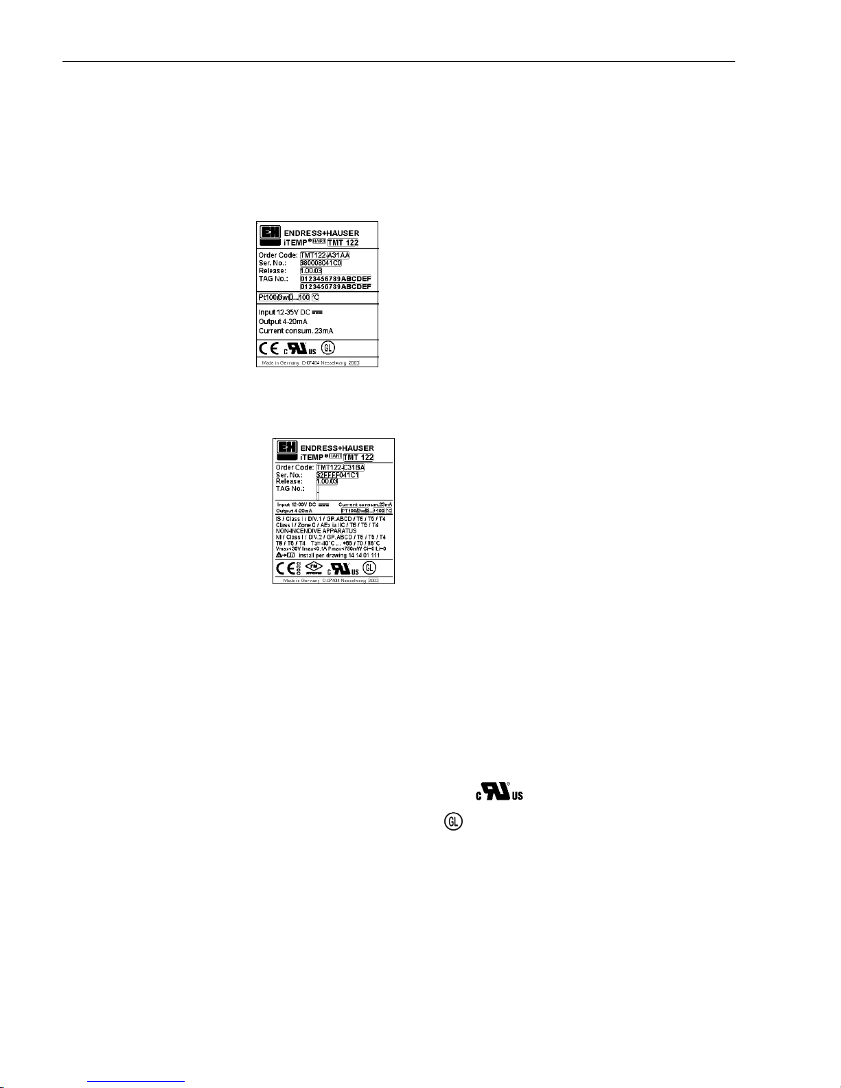
Unit identification Compare the legend plates on the DIN rail transmitter with the following figures:
fig. 1: DIN rail transmitter legend plate (examples)
fig. 2: Identification for hazardous area use (example, only on FM certified units)
CE Mark, declaration of conformity 4
The devices are designed to meet state-of-the-art safety requirements, have been tested, and left the
factory in a condition in which they are safe to operate. The devices comply with the applicable standards and regulations in accordance with IEC61010 "Protection Measures for Electrical Equipment
for Measurement, Control, Regulation and Laboratory Procedures" and with the EMC requirements
of IEC61326.
The measuring system described in these Operating Instructions thus complies with the statutory
requirements of the EC Directives. Endress+Hauser confirms successful testing of the device by affixing to it the CE mark.
UL recognized component to UL 3111-1
GL German Lloyd marine approval
GL Type Approval for temperature measurements in hazardous locations on GL Classed Vessels,
Marine and Offshore Installations.
Page 9

Temperature DIN rail transmitter 3Installation
Endress+Hauser 9
2.2 Registered trademarks
•HART
®
Registered trademark of HART® Communication Foundation, Austin, Tx, USA
• PROFIBUS
®
Registered trademark of PROFIBUS Nutzerorganisation e. V., Karlsruhe, Germany
• Microsoft
®
Windows NT® and Windows® 2000
Registered trademarks of Microsoft Corporation, Redmond, USA
• iTEMP
®
and ReadWin® 2000
are registered trademarks of Endress+Hauser Wetzer GmbH + Co. KG, Nesselwang, Germany
2.3 Delivery contents
Delivery contents The delivery contents of a DIN rail temperature transmitter are as follows:
• Transmitter TMT 122
• Operating instructions
• Control drawing for use in hazardous areas
3Installation
3.1 Installation conditions
Installation conditions Caution!
The unit must only be powered by a power supply that operates using an IEC 61010-1 compliant
energy limited circuit: ’SELV or Class 2 circuit’.
• When installing and operating the unit, please take note of the allowable ambient
temperature (see chapter 10 "Technical Data").
• When using the unit in a hazardous area, the limits indicated in the certification must be adhered
to (see control drawing).
Dimensions
The DIN rail transmitter dimensions can be found in chapter 10 "Technical Data".
Installation point
Installation on DIN rail according to EN 50 022-35, e.g. in control panel.
Installation angle
There are no limits as to the angle of installation.
Page 10
3 Installation Temperature DIN rail transmitter
10 Endress+Hauser
3.2 Installation
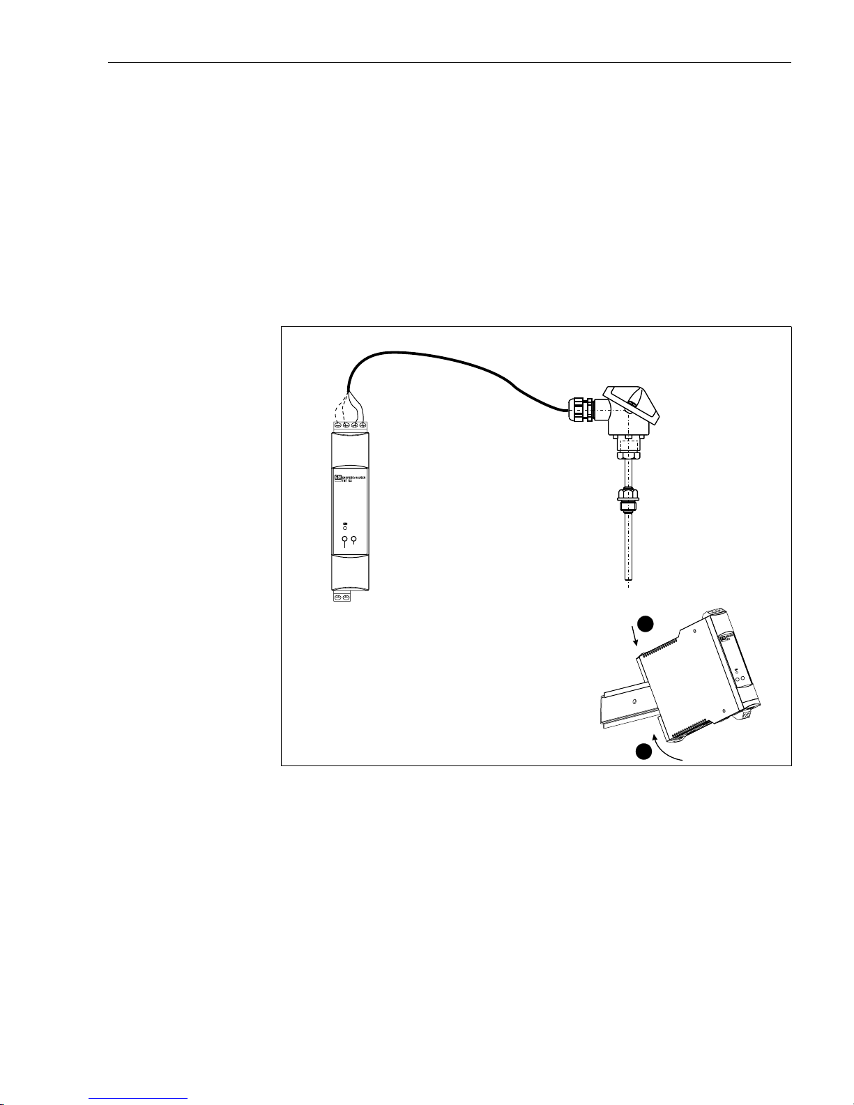
3.2.1 Typical North American installation
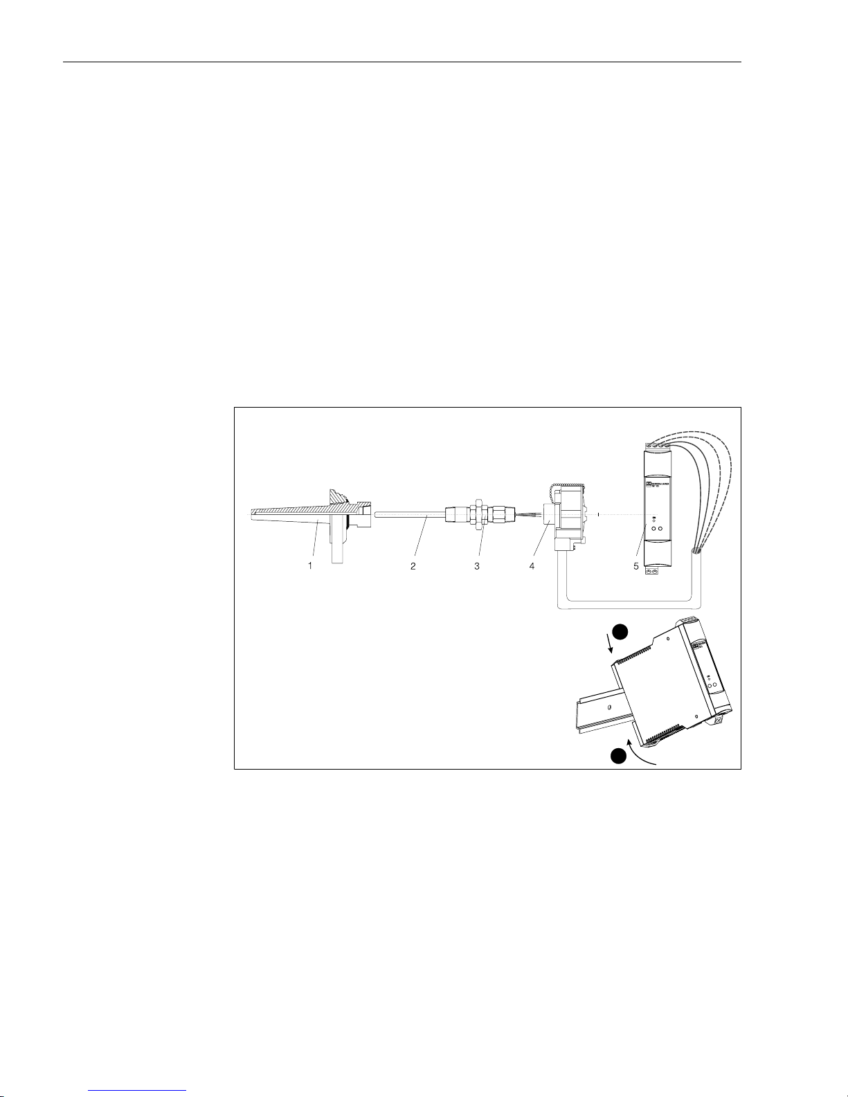
Installation For installation, proceed as follows:
• Attach the TMT 122 transmitter to a suitable rail or panel.
• Attach thermowell (1) to pipe or process container wall. Install and tighten the thermowell before
applying process pressure.
• Attach necessary extension nipples and adapters (3) to the thermowell (1). Seal the nipple and
adapter threads with silicone tape.
• Screw the sensor (2) into the thermowell (1). Install drain seals if required for harsh environments
or to satisfy code requirements.
• Screw the connection head (4) to the sensor assembly.
• Attach the sensor lead wires to the connection head terminals.
• Connect sensor wires from the terminals inside the head to the TMT 122 transmitter (5).
• Install and tighten the connection head cover. Enclosure covers must be completely engaged to
meet explosion-proof area requirements.
fig. 3: Installation of DIN rail TMT 122 transmitter.
1 thermowell
2 sensor
3 extension nipples and adapters
4 connection head
5 TMT 122 transmitter
2
1
35mm
IEC 60715
Page 11
Temperature DIN rail transmitter 3Installation
Endress+Hauser 11
3.2.2 Typical European installation
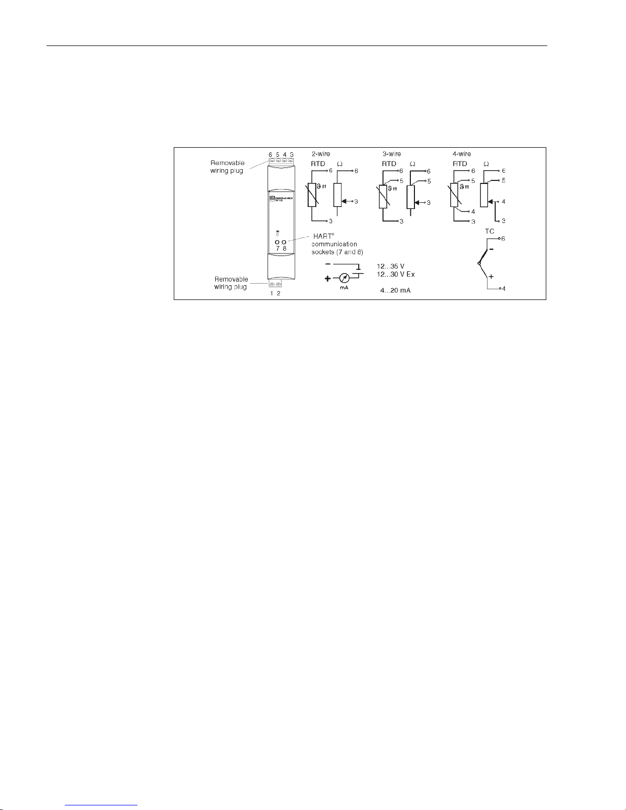
For installation, proceed as follows:
• Attach the TMT 122 transmitter to a suitable rail or panel.
• Attach thermowell to pipe or process container wall. Install and tighten the thermowell before
applying any pressure.
• Attach and connect appropriate lengths of sensor lead wire from the connection head to the sensor terminal block.
• Tighten the connection head cover. Enclosure covers must be completely engaged in order to
meet explosion-proof area requirements.
• Run the sensor lead wires from the sensor assembly to the TMT 122 transmitter.
• Attach the sensor wires to the TMT 122 transmitter.
fig. 4: Installing the TMT 122 DIN rail transmitter
2
1
35mm
IEC 60715
Page 12
4 Wiring Temperature DIN rail transmitter
12 Endress+Hauser
4Wiring
4.1 Overview
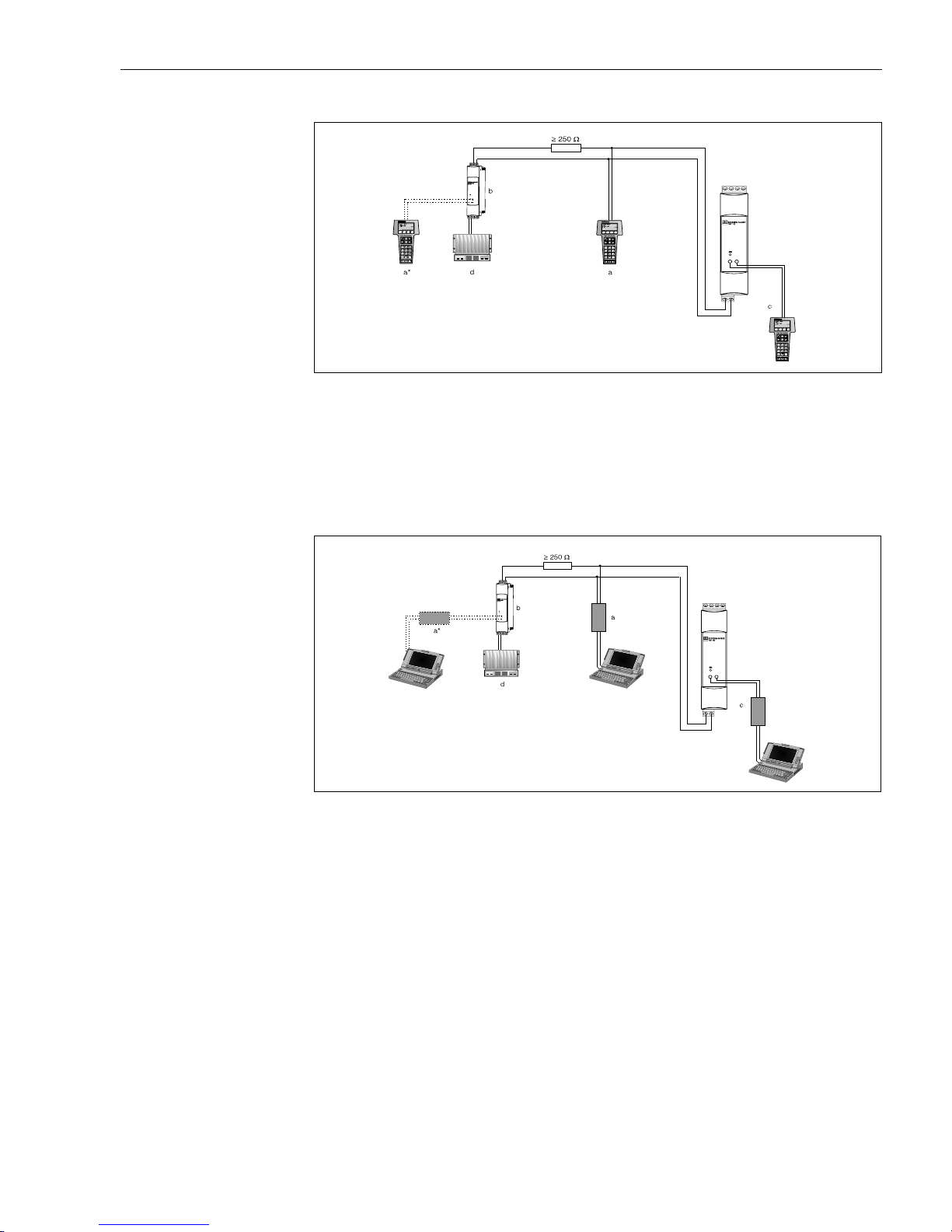
Wiring overview Terminal layout
fig. 5: DIN rail transmitter wiring
4.2 Measurement unit connection
Measurement unit
connection
"
Caution!
Switch off power supply before opening housing cover of the temperature sensor. Do not install or
connect the unit to power supply before the sensor is connected to the transmitter. If this is not followed, parts of the electronic circuit will be damaged.
4.2.1 Sensors
Connect the sensor cables to the respective DIN rail transmitter terminals (Terminals
3 to 6) by following the wiring diagram (see fig. 5). Wiring plugs are removable for easy access.
4.2.2 Output signal and power supply
Connect the cable wires from the power supply to terminal 1 and 2 according to the wiring diagram
(see fig. 5). For convenient installation, the connection is designed as a removable plug, so the connection can be made on the terminals, then plug in the connection socket to the transmitter housing.
!
Note!
The screws on the terminals must be screwed in tightly.
4.2.3 HART® connection
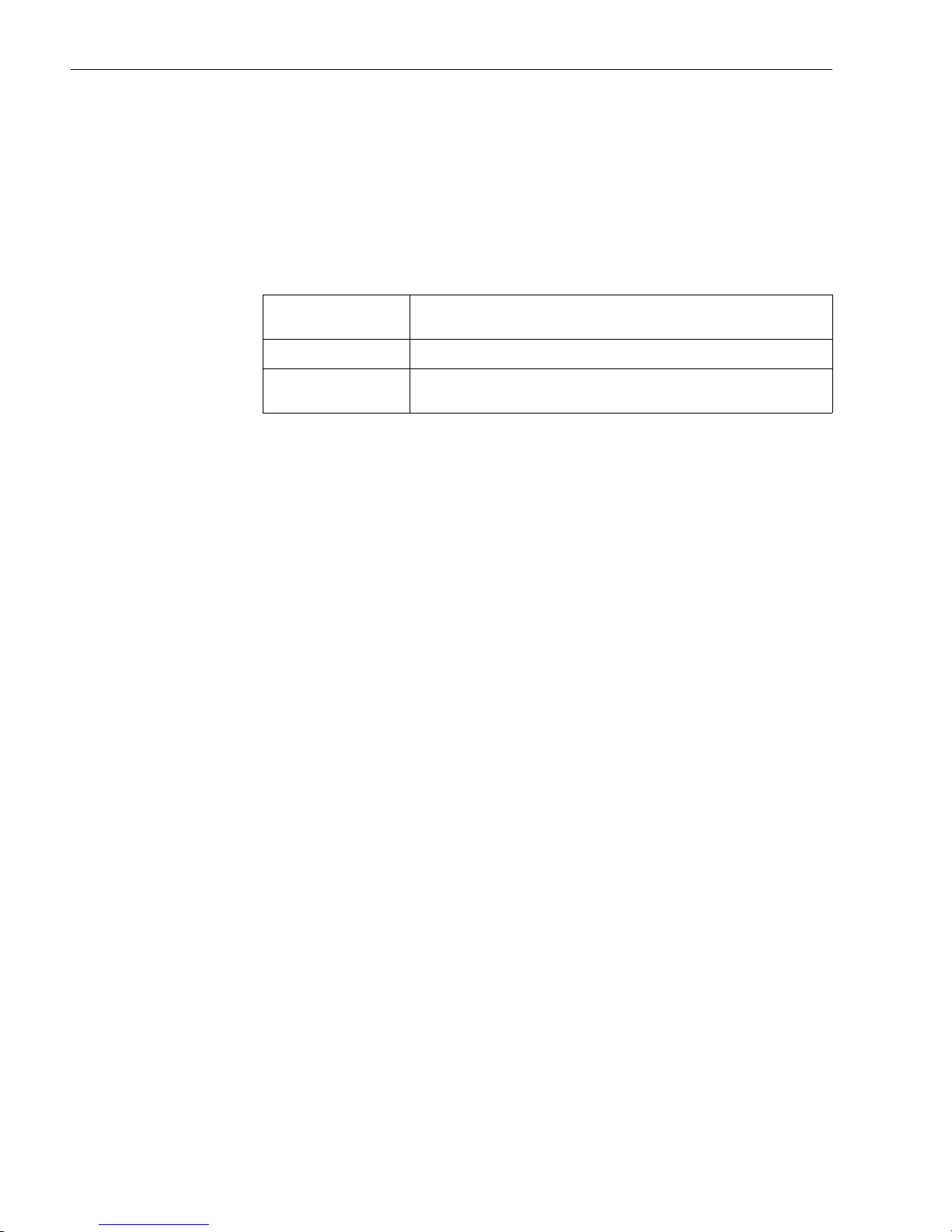
Connection is made directly at the communication socket 7 and 8 at the front wall of the transmitter. The sockets are inside the loop to a power supply or barrier. In order to connect the transmitter
in a hazardous area, please read the separate Ex documentation.
!
Note!
The measurement circuit must have a load of at least 250 Ω. If using the E+H power
supplies RNS 221 and RN 221N, this resistance is already installed in the unit and is therefore not
required externally (see fig. 6, and see fig. 7)!
Page 13
Temperature DIN rail transmitter 4 Wiring
Endress+Hauser 13
Connection of a HART® hand operated module DXR 275/375
fig. 6: Electrical connection of the HART® operated module
a = HART
®
module, a* = HART® module connected to the communication sockets of a power
supply, b = Loop power supply (e.g. RNS 221 power supply or RN 221N active barrier), c = HART® module connected
directly to the transmitter, d = PLC with passive input
Connection of Commubox FXA 191
!
Note!
Set the Commubox DIP switch to ’HART
®
’!
fig. 7: Electrical connection of the Commubox FXA 191
a = Commubox FXA 191 (in combination with a PC - E+H operating software ’Commuwin II’),
a* = Commubox FXA 191 connected to the communication sockets of a power supply unit,
b = Loop power supply (e.g. RNS 221 power supply or RN 221N active barrier), c = Commubox FXA 191 connected directly to the transmitter, d = PLC with a passive input
4.3 Potential grounding
!
Note!
Please take note of the following when installing the transmitter. The shield on the 4 to 20 mA signal
output must have the same potential as the shield at the sensor connections.
In plants with strong electromagnetic fields, shielding of all cables with a low ohm connection to
ground is recommended.
It is recommended that shielded cable be used in installations outside buildings, due to the danger
of lightning strikes.
Page 14

5 Operation Temperature DIN rail transmitter
14 Endress+Hauser
4.4 Ground the Transmitter
The transmitter will operate with the current signal loop either floating or grounded. However, the
extra noise in floating systems affects many types of readout devices. If the signal appears noisy or
erratic, grounding the current signal loop at a single point may solve the problem. The best place to
ground the loop is at the negative terminal of the power supply. Do not ground the current signal
loop at more than one point. The transmitter is galvanically isolated to 2 kV AC (from the sensor
input to the output), so the input circuit may also be grounded at any single point. When using a
grounded thermocouple, the grounded junction serves as this point.
5Operation
5.1 Communication
The temperature DIN rail transmitter is set up using the HART® protocol. The values
measured can also be read using the HART
®
protocol. In order to do this the user has two possibi-
lities:
• Operation using a universal hand operated module “HART
®
Communicator DXR 275/375”.
• Operation using a PC and operating software (e.g. Commuwin II) as well as a HART
®
modem
(e.g. “Commubox FXA 191”).
5.1.1 HART® Communicator DXR 275/375
Selection of the unit functions using the “HART® Communicator” is done using various menu
levels as well as with the help of a special HART
®
function matrix (see page 18).
!
Note!
• When using the HART
®
hand unit all parameters can be read out, however,
programming is locked. It is possible to access the HART
®
function matrix by entering 281 in the
LOCK function. This condition remains even after a power failure. The HART
®
function matrix
can be locked again by entering the personal code number.
• More detailed information on the HART
®
hand operation module can be found in the respective
operating manual in the carrying case.
Page 15

Temperature DIN rail transmitter 5 Operation
Endress+Hauser 15
5.1.2 COMMUWIN II-operating program
Commuwin II is a universal program for remote operation of field and panel-mounted instrumentation. Application of the Commuwin II operating program is possible
independent of the type of unit and communication mode (HART
®
or PROFIBUS®).
Commuwin II offers the following functions:
• Setting up unit functions
• Visualization of measured values
• Data security of unit parameters
• Unit diagnostics
• Measurement point documentation
!
Note!
More detailed information on Commuwin II can be found in the E+H documentation:
• System Information: SI 018F/00/en “Commuwin II”
• Operating manual: BA 124F/00/en “Commuwin II” operating program
More details see:
www.us.endress.com
Page 16
6 Commissioning Temperature DIN rail transmitter
16 Endress+Hauser
6 Commissioning
6.1 Installation and function check
Installation check Monitor all connections making sure they are tight. In order to guarantee fault-free
operation, the terminal screws must be screwed tightly onto the connection cables.
Function check Measuring the analog 4 to 20 mA output signal or following failure signals:
6.2 Commissioning
Commissioning Once the power supply has been connected, the DIN rail transmitter is operational.
!
Note!
If there are any communication faults in the Microsoft
®
Windows NT
®
Version 4.0, Windows®
2000, or Windows
®
XP operating system, please follow these instructions:
Switch of the ’FIFO active’ setting.
In order to do this proceed as follows:
•Windows NT
®
Version 4.0:
Using the menu 'START' 'SETTINGS' 'SYSTEM CONTROL' 'CONNECTIONS' select the menu
point 'COM-Port'. Switch off the ’FIFO active’ command off using the menu path 'SETTINGS’
’EXPANDED'.
•Windows
®
2000:
Select 'Advanced settings for COM1' from the 'START' → 'SETTINGS' → 'SYSTEM CONTROL'
→ 'SYSTEM' → 'HARDWARE' → 'DEVICE MANAGER' → 'CONNECTIONS (COM and LPT)'
→ 'COMMUNICATION CONNECTION (COM1) → 'CONNECTION SETTINGS' → 'ADVAN-
CED' menu. Deactivate "Use FIFO buffer".
•Windows
®
XP:
Select "Port settings" from connections Port (Com 1) → ’START’ → ’SETTING’ → ’SYSTEM’ →
'HARDWARE' → 'DEVICE MANAGER' →'PORTS (COM and LPT)' → 'COMMUNICATION
PORT (COM1) → 'PORT SETTING' → 'ADVANCED' menu. Deactivate "Use FIFO buffer".
6.2.1 Quick Setup
Using the Quick Setup, the operator is led through all the most important unit functions that must
be set up for standard measurement operation of the unit.
Using the HART
®
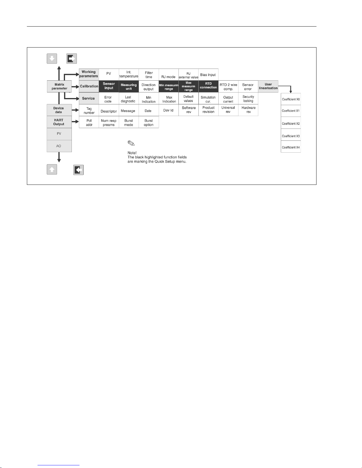
hand module a quick setup of the black highlighted fields of the HART® function
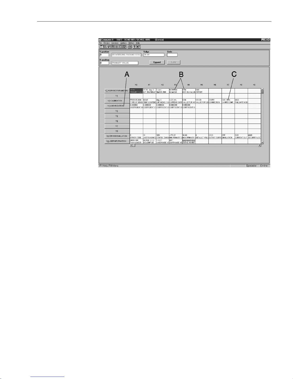
matrix (see fig. 9) is possible. Using the Commuwin II operating matrix (see fig. 10) a quick setup
is possible with the following fields:
• Type of sensor (V2H0)
• Unit meas. value (V2H2)
• Value for 4 mA (V2H4)
• Value for 20 mA (V2H5)
• Connection (V2H6)
Measurement range undercut
linear fall to 3.8 mA
Measurement range excess linear rise to 20.5 mA
Sensor break; sensor short
circuit
a
a. not for thermocouples
≤ 3.6 mA or ≥ 21.0 mA
Page 17
Temperature DIN rail transmitter 6 Commissioning
Endress+Hauser 17
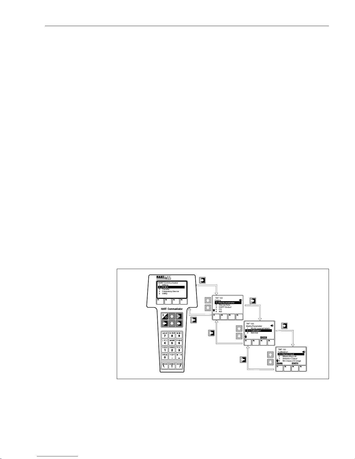
6.2.2 Configuration with HART
®
protocol and DXR 275/375 hand
operated module
!
Note!
Selection of all DIN rail transmitter functions using the HART
®
hand module is done with various
menu levels with the help of the E+H function matrix (see fig. 9). All transmitter functions are
described in 6.2.5 "Description of unit functions".
What needs to be done:
1. Switch on hand module:
– Measurement unit is not yet connected. The HART
®
main menu appears. This menu level
appears for all HART
®
programming independent of the type of instrumentation. Information on off-line programming can be found in the “Communicator DXR 275/375” operating
manual.
– Measuring unit is connected. The menu level “Online” appears. In this “Online” menu level
the actual measured data such as measured value (PV) and output current (AO) are continuously displayed. Entry into the transmitter operating matrix is done using the line “Matrix
Parameter”. This matrix systematically contains all HART
®
accessible functions.
2. Using “Matrix Parameter” the function group can be selected (e.g. basic calibration) and then
followed by the required function, e.g. “Sensor input”.
3. Enter numeric values or change settings. Then acknowledge using the F4 "Entry" function key.
4. "SEND" appears when operating the F2 function key. Once the F2 key has been pressed all
values entered in the hand module are transmitted to the transmitter measurement system.
5. A return to the "Online" menu level is made using the F3 "HOME" function key. Here, the
actual transmitter values measured with the new settings can be read.
!
Note!
• When using the HART
®
hand unit all parameters can be read out, however, programming is blo-
cked. It is possible to access the HART
®
function matrix by entering 281 in the LOCK function.
This condition remains even after a power failure. The HART
®
function matrix can be locked
again by entering the personal code number.
• More detailed information on the HART
®
hand operated module can be found in the respective
operating manual in the carrying case.
fig. 8: Configuration of hand module example, "Sensor input"
Page 18
6 Commissioning Temperature DIN rail transmitter
18 Endress+Hauser
HART® function matrix
fig. 9: HART® function matrix
6.2.3 Configuration with HART
®
protocol and COMMUWIN II
Commuwin II is a universal program for remote operation of field and panel-mounted instrumentation. Application of the Commuwin II operating program is possible independent of the type of
unit and communication mode (HART
®
or PROFIBUS®). Commuwin II offers the following func-
tions:
• Setting up unit functions
• Display
• Data security of unit parameters
• Unit diagnostics
• Measurement point documentation
!
Note!
More detailed information on Commuwin II can be found in the E+H documentation:
• System Information: SI 018F/00/en “Commuwin II”
• Operating manual: BA 124F/00/en “Commuwin II” operating program
More details see:
www.us.endress.com
Page 19
Temperature DIN rail transmitter 6 Commissioning
Endress+Hauser 19
Commuwin II operating matrix
fig. 10: Commuwin II operating matrix:
A = Unit functions active only on customer specific linearization
B = Unit functions active only on TC connection
C = Unit functions active only on RTD 2 wire connection
Page 20

6 Commissioning Temperature DIN rail transmitter
20 Endress+Hauser
6.2.4 Configuration using HART® protocol and PC configuration software ReadWin
®
2000
The configuration of the transmitter can be done using both the HART® protocol and the ReadWin
®
2000 configuration software. The following table shows the structure of the interactive menu
led operation of READWIN
®
2000.
For detailed ReadWin
®
2000 operating instructions, please read the on-line documentation contai-
ned in the ReadWin
®
2000 software. ReadWin® 2000 can be downloaded free of charge from the
Internet at the following address:
• www.readwin2000.com
Customer-specific linearization
Customer-specific linearization and sensor matching are activated after the POLYNOM RTD sen-
sor type is selected. Pressing the “LINEARIZATION” key starts the SMC 32 module. The sensor's
support points and temperature deviation are entered in the SMC 32. Pressing the “CALCU-
LATE” key calculates the linearization and “OK” adopts it into ReadWin
®
2000.
Linearization coefficients X0 to X4 are entered into the COMMUWIN II operating matrix or in the
DXR 275/375 HART
®
handheld terminal.
Configurable parameters (Unit function description see “Description of unit functions” on page 21)
Standard settings – Type of sensor
– Connection mode (2-,3-, or 4-wire connection on RTD)
– Units (°C, °F or K)
– Measurement range start value
– Measurement range end value
– Coefficient X0 to X4 (on sensor type polynom RTD/TC)
– Temp.-compensation (on sensor type polynom TC)
Expanded settings – Cold junction compensation internal/external (on TC)
– Temperature external (on TC with cold junction compensation external)
– Cable resistance compensation (on RTD 2-wire connection)
– Fault condition reaction
– Output (4 to 20 mA/20 to 4 mA)
– Damping (filter)
–Offset
– TAG (Measurement point description)
– Identifier (Descriptor)
Service functions – Simulation (on/off)
– Reset/factory default
– Series number (only display)
– Operation code (=release code 281)
Page 21

Temperature DIN rail transmitter 6 Commissioning
Endress+Hauser 21
6.2.5 Description of unit functions
The following table contains a listing and description of all unit functions of the HART® protocol
that can be used for setting up the temperature DIN rail transmitter.
!
Note!
Factory default values are shown in bold text.
The HART
®
operating module (DXR275/375) display is indicated by the following symbol 7.
Function group: WORKING PARAMETERS
Primary value
•V0H0
• 7 (PV)
Display of actual measured temperature.
Display: 7-digit number with floating decimal point and engineering unit.
(e.g. 199.98 Ohm; -62.36 °C, 407.76 °F)
Int: temperature
•V0H1
Display of the actual measured temperature of the internal comparison measurement
point.
! Note!
Display: 7-digit number with floating decimal point and engineering unit. (e.g. 23.70
°C, 71.04 °F)
a
a. Only for Commuwin II operating matrix
Time filter
•V0H2
Digital filter selection 1st grade.
Input: 0 to 100 seconds
0 sec.
RJ Mode
•V0H3
Selection of internal (Pt100) or external (32 to 176 °F/0 to 80 °C) cold
junction compensation.
Entry: internal; external
internal
! Note!
Entry only possible on selection of thermocouple (TC) in unit function
SENSOR TYPE.
1
Ext. RJ Value
•V0H4
Entry of external cold junction value.
Entry: -40.00 to 185.00 °F (-40.00 to 85.00 °C) (°C, °F, K)
0 °C
! Note!
Entry only possible on selection of an external cold junction compensation in unit
function RJ MODE.
OFFSET
•V0H5
Entry of zero point correction (Offset).
Entry: -18.00 to 18.00 °F (10.00 to 10.00 °C) (°C, °F, K)
0.00 °C
! Note!
Entry returns to factory default values when changing sensor type!
Page 22

6 Commissioning Temperature DIN rail transmitter
22 Endress+Hauser
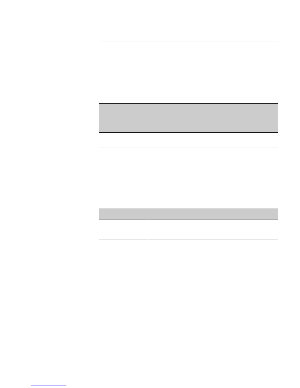
Function group: BASIC CALIBRATION
Type of sensor
•V2H0
Entry of sensor used:
Sensor type Range start Range end value
-10..75 mV -10 mV 75 mV
10..400 Ohm 10 Ω 400 Ω
10..2000 Ohm 10 Ω 2000 Ω
Pt100 DIN -200 °C (-328 °F) 850 °C (1562 °F)
Pt100 JIS -200 °C (-328 °F) 649 °C (482 °F)
Pt500 -200 °C (-328 °F) 250 °C (482 °F)
Pt1000 -200 °C (-328 °F) 250 °C (482 °F)
Ni100 -60 °C (-76 °F) 180 °C (356 °F)
Ni500 -60 °C (-76 °F 150 °C (302 °F)
Ni1000 -60 °C (-76 °F 150 °C (302 °F)
Polynom RTD -270 °C (-454 °F) 2500 °C (4532 °F)
Type B 0 °C (32 °F) 1820 °C (3308 °F)
Type C 0 °C (32 °F) 2320 °C (4208 °F)
Type D 0 °C (32 °F) 2495 °C (4523 °F)
Type E -270 °C (-454 °F) 1000 °C (1832 °F)
Type J -210 °C (-346 °F) 1200 °C (2192 °F)
Type K -270 °C (-454 °F) 1372 °C (2501 °F)
Type L -200 °C (-328 °F) 900 °C (1652 °F)
Type N -270 °C (-454 °F) 1300 °C (2372 °F)
Type R -50 °C (-58 °F) 1768 °C (3214 °F)
Type S -50 °C (-58 °F) 1768 °C (3214 °F)
Type T -270 °C (-454 °F) 400 °C (752 °F)
Type U -200 °C (-328 °F) 600 °C (1112 °F)
Pt100 DIN
Unit meas. value
•V2H2
Enter engineering units.
Entry: °C
°F
K
°C
Current output
•V2H3
Enter standard (4 to 20 mA) or inverse (20 to 4 mA) current output signal.
Entry: 4 to 20 mA
20 to 4 mA
4 to 20 mA
Value for 4 mA
•V2H4
Entry: For limits see unit function SENSOR TYPE.
0 °C
Value for 20 mA
•V2H5
Entry: For limits see unit function SENSOR TYPE.
100 °C
Connection
•V2H6
•
7
RTD connection
Entry of RTD connection mode
Entry: 2 wire
3 wire
4 wire
3 wire
! Note!
Function field is only active on selection of resistance thermometer (RTD) in the unit
function SENSOR TYPE (V2H0)
a
.
a. Only for Commuwin II operation matrix
Page 23
Temperature DIN rail transmitter 6 Commissioning
Endress+Hauser 23
2 wire comp.
•V2H7
Entry of cable compensation on RTD 2 wire connection.
Entry: 0.00 to 30.00 Ohm
0.00 Ohm
! Note!
Function field is only active on selection of 2 wire cable connection in unit function
CONNECTION TYPE (V2H6)a.
a. Only for Commuwin II operation matrix
Failsafe mode
•V2H8
Entry of failure signal on sensor open or short circuit.
b
Entry: max (≥ 21.0 mA)
min (≤ 3.6 mA)
max
b. Not for thermocouples (TC)
Function group: LINEARIZATION
7 USER linearization
The following function fields are only active in the unit function SENSORTYPE (V2H0) on selection of customer-speci-
fic linearization (polynome RTD or polynome TC).
1
Coefficient X0
•V3H0
Input of first coefficient for customer-specific linearization (polynome
4
th
grade with five coefficients), see chapter 6.2.4
Coefficient X1
•V3H1
Input COEFFICIENT X1, see chapter 6.2.4.
Coefficient X2
•V3H2
Input
COEFFICIENT X2, see chapter 6.2.4.
Coefficient X3
•V3H3
Input
COEFFICIENT X3, see chapter 6.2.4.
Coefficient X4
•V3H4
Input
COEFFICIENT X4, see chapter 6.2.4.
Function group: SERVICE
Error code
•V9H0
Display of actual error code.
Display: See “Application fault messages” on page 26.
0
Last diagnostic
•V9H1
Display of previous error code.
Display: See “Application fault messages” on page 26.
0
Config. changed
•V9H2
Parameter changes are done.
Display: Yes/No
No
Min primary value
•V9H3
Display the minimum process value. The process value is accepted at the beginning of
the measurement.
! Note!
Min. process value will be changed to the actual process value on access. On reset to
factory default, the default value is entered.
+10000
Page 24

6 Commissioning Temperature DIN rail transmitter
24 Endress+Hauser
Max primary value
•V9H4
Display the maximum process value. The process value is accepted at the beginning
of the measurement.
! Note!
Max. process value will be changed to the actual process value on access. On reset to
factory default, the default value is entered.
-10000
Default values
•V9H5
Entry: 182 (Reset to factory default settings)
0
Output current
•V9H6
Display of the actual output current signal.
Simulation
•V9H7
Entry of simulation mode.
Entry: Off
On
Off
Current out (sim)
•V9H8
Entry of simulation value (current).
Entry: 3.58 to 21.7 mA
Security locking
•V9H9
Release code for setting up.
Entry: Lock = 0
Release = 281
281
Function group: USER INFORMATION
Tag number
•VAH0
Entry and display of measurement point description (TAG).
Entry: 8 characters
-
Descriptor
•VAH1
Entry and display of plant description.
Entry: 16 characters
-
Hardware Version
•VAH2
Display of unit version,
e.g.: 1.0000 indicates version 1.00.00.
Software Version
•VAH3
•
7 Software Rev.
Display of software version,
e.g.:
8010 indicates version 1.0
8011 indicates version 1.1
Serial number
•VAH4
8-digit display of E+H device serial numbers (see legend plates on the device).
Page 25
Temperature DIN rail transmitter 6 Commissioning
Endress+Hauser 25
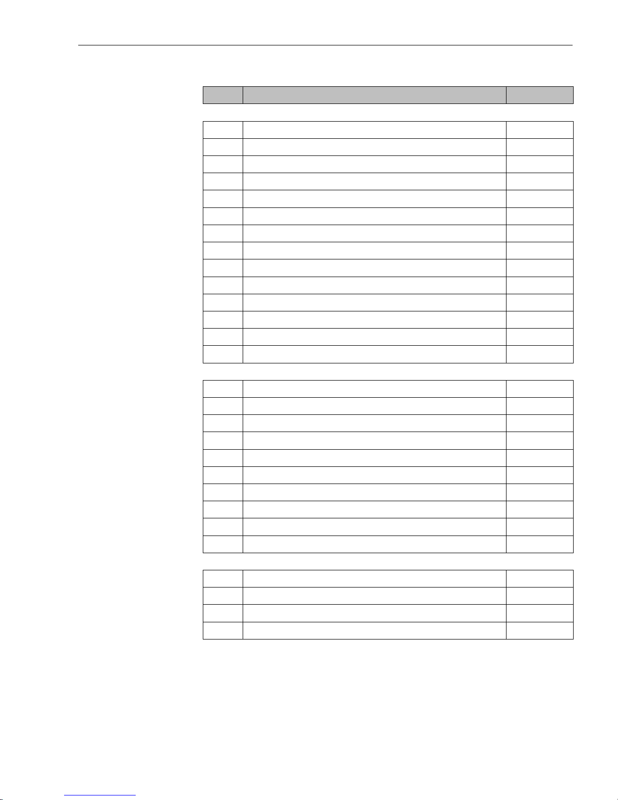
6.2.6 Supported HART® commands
No. Description Access
Universal Commands
00 Read unique identifier r
01 Read primary variable r
02 Read p.v. current and percent of range r
03 Read dynamic variables and p.v. current r
06 Write polling address w
11 Read unique identifier associated with tag r
12 Read message r
13 Read tag, descriptor, date r
14 Read primary variable sensor information r
15 Read primary variable output information r
16 Read final assembly number r
17 Write message w
18 Write tag, descriptor, date w
19 Write final assembly number w
Common practice
34 Write primary variable damping value w
35 Write primary variable range values w
38 Reset configuration changed flag w
40 Enter/Exit fixed primary varaible current mode w
42 Perform master reset w
44 Write primary variable units w
48 Read additional transmitter status r
59 Write number of response preambles w
108 Write burst mode command number w
109 Burst mode control w
E+H specific
144 Read matrix parameter r
145 Write matrix parameter w
148 Upload r
149 Download w
Page 26
7 Maintenance Temperature DIN rail transmitter
26 Endress+Hauser
7 Maintenance
Maintenance The TMT 122 temperature DIN rail transmitter has no moving parts and requires minimal sche-
duled maintenance.
Sensor Checkout
To determine whether the sensor is at fault, replace it with another sensor or connect a test sensor
locally at the transmitter to test remote sensor wiring. Select any standard, off-the-shelf sensor for
use with a TMT122 temperature transmitter, or consult the factory for a replacement special sensor
or transmitter combination.
8 Accessories
Accessories Commubox FXA 191, PC-Software Commuwin II and ReadWin® 2000, DIN rail clip according to
IEC 60715 for E+H temperature DIN rail transmitters
ReadWin
®
2000 can be downloaded free of charge from the internet from the following address:
www.readwin2000.com
Please contact your supplier when ordering!
9 Trouble-shooting
9.1 Trouble-shooting instructions
If faults occur after commissioning or during measurement, always start any trouble-shooting
sequence using the following check. The user is led towards the possible fault cause and its rectification via question and answer.
9.2 Application fault messages
Application fault
messages
Application fault messages are shown in the display of the HART® hand operating
module "DXR 275/375" once the menu point "ERROR CODE" has been selected or in the PC operating surface of Commuwin II (V9H0 - ERROR CODE)
.
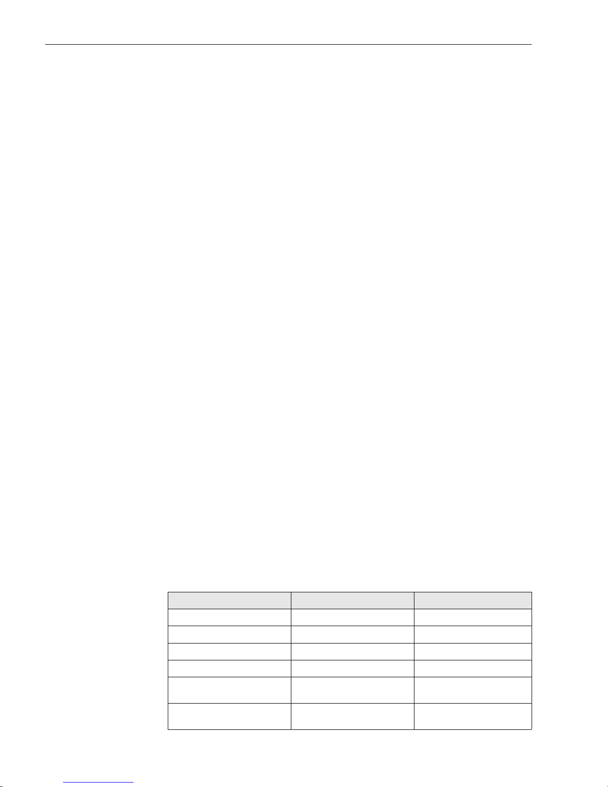
Fault code Cause Action/cure
0 No fault, Warning None
10 Hardware fault (unit defective) Replace DIN rail transmitter
11 Sensor short circuit Check sensor
12 Sensor cable open circuit Check sensor
13 Reference measurement point defec-
tive
None
14 Unit not calibrated Return DIN rail transmitter to
manufacturer
Page 27
Temperature DIN rail transmitter 9 Trouble-shooting
Endress+Hauser 27
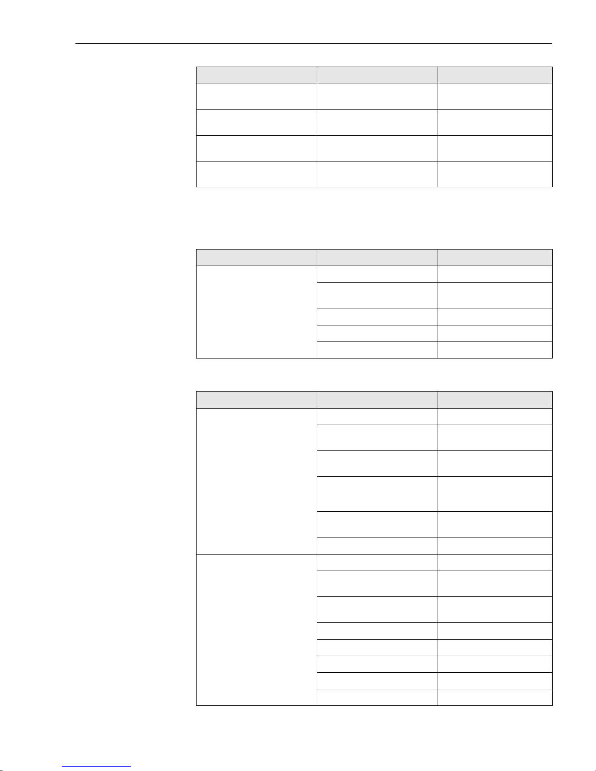
9.3 Application faults without messages
Application fault without
messages
General application faults
Application faults for RTD connection (Pt100/Pt500/Pt1000/Ni100)
106 Up-/Download active None (will be automatically
acknowledged)
201 Warning: Measured value too small Enter other values for measured
value range start
202 Warning: Measured value too large Enter other values for measured
value range end
203 Unit is reset (to factory default
settings)
None
Fault code Cause Action/cure
Fault Cause Action/cure
No communication No power supply on 2 wire circuit Check current loop
Power supply too low (<10 V) Connect cables correctly to terminal
plan (polarity)
Defective interface cable Check interface cable
Defective interface Check PC interface
Defective DIN rail transmitter Replace DIN rail transmitter
Fault Cause Action/cure
Fault current
(≤ 3.6 mA or ≥ 21 mA)
Defective sensor Check sensor
Incorrect RTD connection Reconnect cables correctly (connec-
tion diagram)
Incorrect 2 wire connection Connect cables correctly to terminal
plan (polarity)
Transmitter programming faulty (wire
number)
Change parameter ’CONNECTION’
(See “Description of unit functions”
on page 21.)
Programming Thermocouple set up (see
chapter 6.2.5); change to RTD
Defective DIN rail transmitter Replace DIN rail transmitter
Measured value incorrect/inaccurate Faulty sensor installation Install sensor correctly
Heat conducted via sensor Take note of sensor installation
length
Transmitter programming faulty (wire
number)
Change parameter ‘Connection type’
Transmitter programming faulty (scale) Change scale
Wrong RTD used Change parameter ‘Sensor type’
Sensor connection (2 wire) Check sensor connections
Sensor cable (2 wire) not compensated Compensate cable resistance
Offset incorrectly set Check offset
Page 28
9 Trouble-shooting Temperature DIN rail transmitter
28 Endress+Hauser
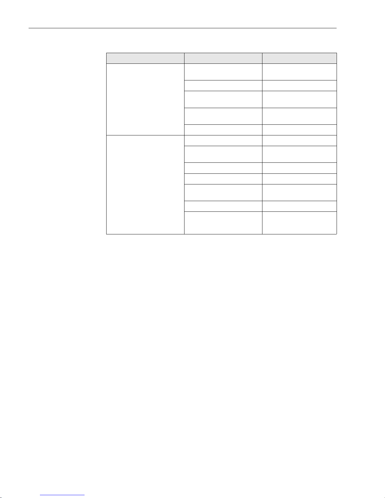
Application faults for TC connection
9.4 Returns
Returns Please follow the return Authorization Policy at the end of these instructions.
9.5 Disposal
Disposal Due to its construction, the DIN rail transmitter cannot be repaired. When disposing of the DIN rail
transmitter please take note of the local disposal regulations.
Fault Cause Action/cure
Fault current
(≤ 3.6 mA or ≥ 21 mA)
Sensor incorrectly connected Connect sensor correctly to
terminal plan (polarity)
Defective sensor Replace sensor
Programming Sensor type ’RTD’ setup; set up cor-
rect thermocouple
Incorrect 2 wire connection (current
loop)
Connect the cables correctly (see
connection diagram)
Defective DIN rail transmitter Replace DIN rail transmitter
Measured value incorrect/inaccurate Faulty sensor installation Install sensor correctly
Heat conducted via sensor Take note of sensor installation
length
Transmitter programming faulty (scale) Change scale
Incorrect thermocouple setup Change parameter ‘Sensor type’
Incorrect cold junction setup See chapter ‘Operation’ and ‘Techni-
cal data’
Offset incorrectly set up Check offset
Fault on the thermowell welded
thermo wire (coupling of interference
voltages)
Use sensor where the thermo wire is
not welded
Page 29

Temperature DIN rail transmitter 10 Technical Data
Endress+Hauser 29
9.6 Software history
10 Technical Data
10.1 Function and system design
Measuring principle Electronic monitoring and conversion of input signals in industrial temperature measurement.
Measuring system The iTEMP
®
HART® DIN rail TMT 122 temperature DIN rail transmitter is a two wire transmitter
with an analog output. It has measurement input for resistance thermometers (RTD) in 2-, 3- or 4wire connection, thermocouples and voltage transmitters. Setup of the TMT 122 is done using the
HART
®
-Protocol with hand operating module (DXR 275/375) or PC (COMMUWIN II or Read-
Win
®
2000 operating software).
10.2 Input
Measured variable Temperature (temperature linear transmission behavior), resistance and voltage
Measuring range The transmitter monitors different measuring ranges depending on the sensor connection and input
signals.
Software version / date Changes to software Changes to documentation
V 1.1 / 12.2001 Original software
compatible with:
•HART® Communicator DXR
275/375 (from OS 4.6) with DevRev 2, DDRev 1
•Readwin® 2000
• Commuwin II (version 2.07.01-4
and higher
• AMS (version 5.X and higher)
• PDM (version 5.2 and higher)
Page 30
10 Technical Data Temperature DIN rail transmitter
30 Endress+Hauser
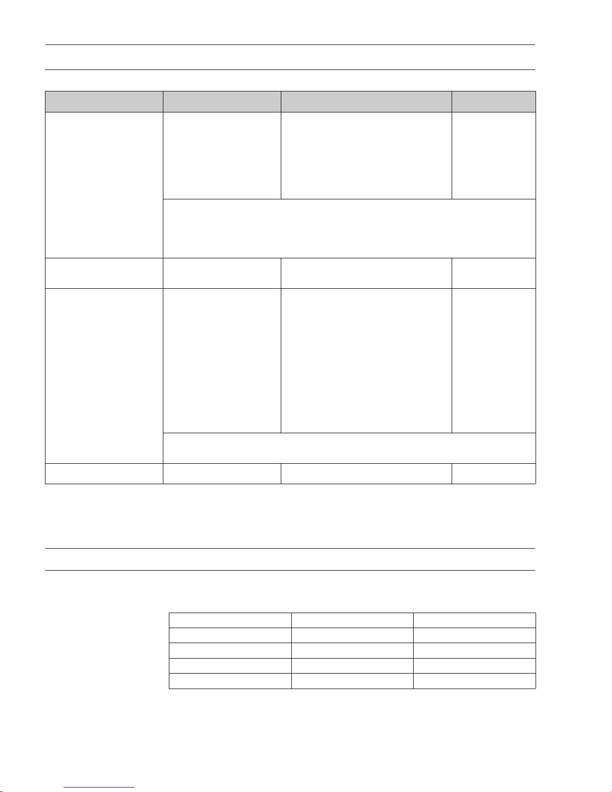
Type of input
10.3 Output
Output signal Analog 4 to 20 mA, 20 to 4 mA
Breakdown information Breakdown information to NAMUR NE 43
Breakdown information is created when the measuring information is invalid or not present anymore and gives a complete listing of all errors occuring in the measuring system.
Input Designation Measuring range limits Min. span
Resistance thermometer (RTD)
to IEC 751
(α = 0.00385)
to DIN 43760
(α = 0.006180)
Pt100
Pt500
Pt1000
Ni100
Ni500
Ni1000
-328 to 1562 °F (-200 to 850 °C)
-328 to 482 °F (-200 to 250 °C)
-328 to 482 °F (-200 to 250 °C)
-76 to 482 °F (-60 to 250 °C)
-76 to 302 °F (-60 to 150 °C)
-76 to 302 °F (-60 to 150 °C)
18 °F (10 °C)
18 °F (10 °C)
18 °F (10 °C)
18 °F (10 °C)
18 °F (10 °C)
18 °F (10 °C)
• Connection type: 2-, 3- or 4-wire connection
• Software compensation of cable resistance possible in the 2 wire system
(0 to 30 Ω)
• Sensor cable resistance max. 20 Ω per cable in the 3 and 4 wire system
• Sensor current: ≤ 0.2 mA
Resistance transmitter Resistance Ω 10 to 400 Ω
10 to 2000 Ω
10 Ω
100 Ω
Thermocouples (TC)
to NIST Monograph 175,
IEC 584
to ASTM E988
to DIN 43710
Type B (PtRh30-PtRh6)
a
Type E (NiCr-CuNi)
Type J (Fe-CuNi)
Type K (NiCr-Ni)
Type N (NiCrSi-NiSi)
Type R (PtRh13-Pt)
Type S (PtRh10-Pt)
Type T (Cu-CuNi)
Type C (W5Re-W26Re)
Type D (W3Re-W25Re)
Type L (Fe-CuNi)
Type U (Cu-CuNi)
32 to 3308 °F (0 to +1820 °C)
-454 to 1832 °F (-270 to +1000 °C)
-346 to 2192 °F (-210 to +1200 °C)
-454 to 2501 °F (-270 to +1372 °C)
-454 to 2372 °F (-270 to +1300 °C)
-58 to 3214 °F (-50 to +1768 °C)
-58 to 3214 °F (-50 to +1768 °C)
-454 to 752 °F ( -270 to +400 °C)
32 to 4208 °F (0 to +2320 °C)
32 to 4523 °F (0 to +2495 °C)
-328 to 1652 °F (-200 to +900 °C)
-328 to 1112 °F (-200 to +600 °C)
900 °F (500 °C)
90 °F (50 °C)
90 °F (50 °C)
90 °F (50 °C)
90 °F (50 °C)
900 °F (500 °C)
900 °F (500 °C)
90 °F (50 °C)
900 °F (500 °C)
900 °F (500 °C)
90 °F (50 °C)
90 °F (50 °C)
• Internal cold junction (Pt100)
• Accuracy of cold junction: ± 1.8 °F (1 °C)
Voltage transmitter (mV) Millivolt transmitter (mV) -10 to 75 mV 5 mV
a.High measuring error increase for temperature lower than 572 °F (300 °C)
Signal (mA)
Under ranging Standard 3.8
Over ranging Standard 20.5
Sensor break; sensor short circuit low To NAMUR NE 43 ≤ 3.6
Sensor break; sensor short circuit high To NAMUR NE 43 ≥ 21.5
Page 31
Temperature DIN rail transmitter 10 Technical Data
Endress+Hauser 31
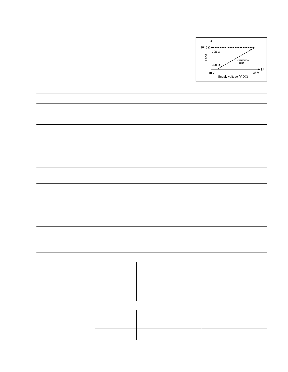
Source impedance max. (V
Power supply
- 12 V) / 0.022 A (current output)
e.g. (24 V-12 V)/0.022 A = 545.5 Ω
Transmission behavior Temperature linear, resistance linear, voltage linear
Filter 1st order digital filter: 0 to 100 s
Galvanic isolation U = 2 kV AC (input/output)
Input current required ≤ 3.5 mA
Current limit ≤ 23 mA
Switch on delay 4 s (during power up I
a
≤ 3.8 mA)
10.4 Power supply
Electrical connection See “Overview” on page 12.
Supply voltage U
b
= 12 to 35 V, polarity protected (For hazardous location please see control drawing)
Residual ripple Allowable ripple U
ss
≤ 3 V at Ub ≥ 13 V, f
max.
= 1 kHz
10.5 Performance characteristics
Response time 1 s
Reference operating
conditions
Calibration temperature: 73.4 °F ± 9 °F (+23 °C ± 5 °C)
Maximum measured error
Type Measurement accuracy
1
Resistance thermometer
RTD
Pt100, Ni100
Pt500, Ni500
Pt1000, Ni1000
0.36 °F (0.2 °C) or 0.08%
0.9 °F (0.5 °C) or 0.20%
0.54 °F (0.3 °C) or 0.12%
Thermocouple TC
K, J, T, E, L, U
N, C, D
S, B, R
typ. 0.9 °F (0.5 °C) or 0.08%
typ. 1.8 °F (1.0 °C) or 0.08%
typ. 3.6 °F (2.0 °C) or 0.08%
Measurement range Measurement accuracy
a
a.% is related to the adjusted measurement range. The value to be applied is the greater.
Resistance transmitter
(Ω)
10 to 400 Ω
10 to 2000 Ω
± 0.1 Ω or 0.08%
± 1.5 Ω or 0.12%
Voltage transmitters
(mV)
-10 to 75 mV ± 20 µV or 0.08%
Page 32

10 Technical Data Temperature DIN rail transmitter
32 Endress+Hauser
Influence of supply voltage ≤ ±0.01%/V deviation from 24 V
Percentages refer to the full scale value.
Influence of ambient temperature (Temperature
drift)
• Resistance thermometer (RTD):
T
d
= ±(8.3 ppm/°F * max. span + 27.8 ppm/°F * calibrated span) * ∆ ϑ
T
d
= ±(15 ppm/K * max. span + 50 ppm/K * calibrated span) * ∆ ϑ
• Resistance thermometer Pt100:
T
d
= ±(8.3 ppm/°F * (full scale point or 20 mA temperature + 328) + 27.8 ppm/°F * span) * ∆ ϑ
T
d
= ±(15 ppm/K * (full scale point or 20 mA temperature + 200) + 50 ppm/K * span) * ∆ ϑ
• Thermocouple (TC):
T
d
= ±(27.8 ppm/°F * max. span + 27.8 ppm/°F * calibrated span) * ∆ ϑ
T
d
= ±(50 ppm/K * max. span + 50 ppm/K * calibrated span) * ∆ ϑ
Influence of load ± 0.02%/100 Ω
Values refer to the full scale value
Long-term stability ≤ 0.18 °F/year (0.1 °C/year) or ≤ 0.05%/year
Values under reference operating conditions. % refer to the set span. The highest value is valid.
Influence of cold junction Pt100 IEC 751 Cl. B (internal cold junction for thermocouples TC)
10.6 Installation conditions
Installation instructions • Installation angle:
no limit
• Installation area:
Installation on DIN rail, e.g. in control panel
∆ ϑ Deviation of the ambient temperature according to the reference condition (73.4 °F ± 9
°F) (+23 °C ± 5 K).
Calibrated span 100 °F if unit calibrated from 50 °F to 150 °F.
max. span Pt100 would be 1890 °F (1050 °C).
Full scale point or 20
mA temperature
150 °F if unit calibrated from 50 °F to 150 °F.
Page 33
Temperature DIN rail transmitter 10 Technical Data
Endress+Hauser 33
10.7 Environmental conditions
Ambient temperature
limits
-40 to 185 °F (-40 to +85 °C) for Ex-area, see Ex-certification or control drawing
Storage temperature -40 to 212 °F (-40 to +100 °C)
Climate class as per IEC 60654-1, class C
Condensation allowed
Degree of protection NEMA 1 (IP 20)
Shock and vibration resistance
4g / 2 to 150 Hz as per IEC 60 068-2-6
Electromagnetic compatibility (EMC)
CE Electromagnetic Compatibility Compliance
The device meets all requirements listed under IEC 61326 Amendment 1, 1998 and
NAMUR NE 21
This recommendation is a uniform and practical way of determining whether the devices used in
laboratory and process control are immune to interference with an objective to increase its functional safety.
10.8 Mechanical construction
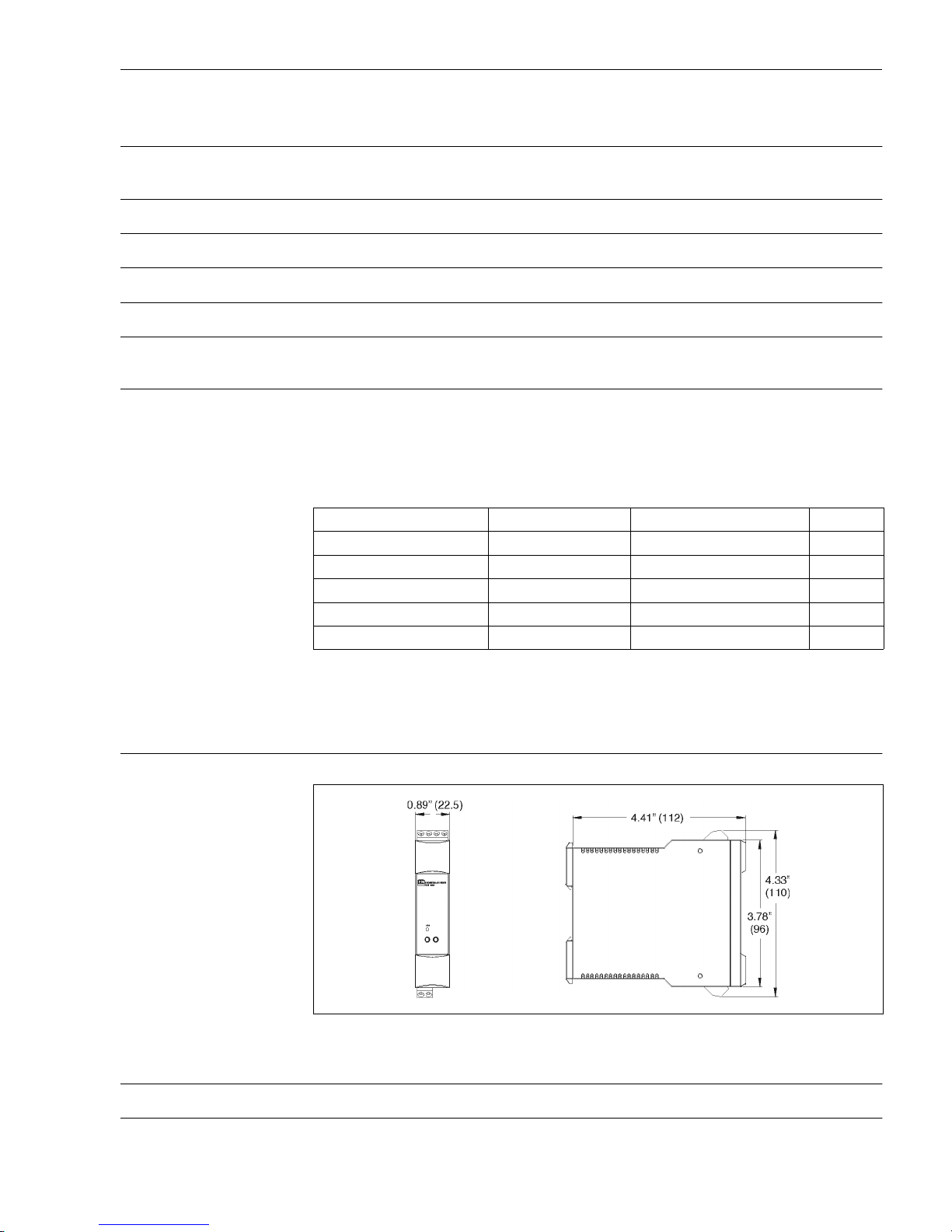
Design, dimensions
fig. 11: Dimensions of the DIN rail transmitter in inches (mm)
Weight approx. 3.2 oz (90 g)
Material • Housing:
Discharge of static electricity IEC 61000-4-2 6 kV cont., 8 kV air
Electromagnetic fields IEC 61000-4-3 80 to 1000 Hz 10 V/m
Burst (signal) IEC 61000-4-4 1 kV 2 kV(B)
a
a. self recovery
Transient voltage IEC 61000-4-5 1 kV unsym. / 0.5 kV sym.
HF coupling IEC 61000-4-6 0.15 to 80 MHz 10 V
Line interference IEC 61000-4-16 10 kHz to 150 kHz 10 V
Page 34

10 Technical Data Temperature DIN rail transmitter
34 Endress+Hauser
Plastic PC/ABS, UL 94V0
Terminals Keyed plug-in screw terminals, core size max. 16 AWG solid, or strands with ferrules.
10.9 Human interface
Display elements No display elements are present directly on the temperature transmitter.
The measured value display can be called up using the ReadWin
®
2000 or
COMMUWIN II PC software.
Operating elements No operating elements are present directly on the transmitter to prevent manipulation. The device
parameters of the temperature transmitter are configured using the DXR 275/375 handheld terminal or a PC with Commubox FXA 191 and operating software (e.g. COMMUWIN II or ReadWin
®
2000)
Remote operation Configuration
Handheld terminal DXR 275/375 or PC with Commubox FXA 191 and operating software
(ReadWin
®
2000 or COMMUWIN II).
Interface
PC interface RS232 and Commubox FXA 191.
Configurable parameters
Sensor type and connection type, engineering units (°C/°F), measurement range, internal/external
cold junction, compensation of wire resistance with 2-wire connection, failure mode, output signal
(4 to 20/20 to 4 mA), digital filter (damping), offset, TAG + descriptor (8 + 16 characters), output
simulation, customer specific linearization, min./max. process value indicator function
10.10 Certificates and approvals
CE-Mark The measurement system fulfills the requirements demanded by the EU regulations. Endress+Hau-
ser acknowledges successful unit testing by adding the CE mark.
Hazardous area
approvals
• FM IS, Class I, Div. 1+2, Group A, B, C, D / FM NI, Class I, Div. 2, Group A, B, C, D
• CSA IS, Class I, Div. 1+2, Group A, B, C, D
• ATEX II1G EEx ia IIC T4/T5/T6
• ATEX II3G EEx nA IIC T4/T5/T6
• ATEX II3D in compliance with EN 50281.1
GL Ship building approval (Germanischer Lloyd)
UL Recognized component to UL 3111-1
Other standards and
guidelines
• IEC 60529:
Degrees of protection by housing (IP-Code)
• IEC 61010:
Safety requirements for electrical measurement, control and laboratory instrumentation.
• IEC 61326:
Electromagnetic compatibility (EMC requirements)
•NAMUR
Standardization association for measurement and control in chemical and pharmaceutical industries. (www.namur.de)
•NEMA
Standardization association for the electrical industry
Page 35

Temperature DIN rail transmitter Index
Endress+Hauser 3
5
Index
C
CE-marks . . . . . . . . . . . . . . . . . . . . . . . . . . . . . . . . . . . . . . 8
Commubox FXA 191 . . . . . . . . . . . . . . . . . . . . . . . . . . . . 13
Commuwin II operating matrix . . . . . . . . . . . . . . . . . . . . . 19
Commuwin II operating program. . . . . . . . . . . . . . . . . . . . 15
conformity description. . . . . . . . . . . . . . . . . . . . . . . . . . . . . 8
Customer-specific linearization . . . . . . . . . . . . . . . . . . . . . 20
D
Dimensions. . . . . . . . . . . . . . . . . . . . . . . . . . . . . . . . . . . . . 9
F
Fault code . . . . . . . . . . . . . . . . . . . . . . . . . . . . . . . . . . . . . 26
FIFO active . . . . . . . . . . . . . . . . . . . . . . . . . . . . . . . . . . . . 16
Function group
BASIC CALIBRATION . . . . . . . . . . . . . . . . . . . . . . . . . 22
LINEARIZATION. . . . . . . . . . . . . . . . . . . . . . . . . . . . . 23
SERVICE . . . . . . . . . . . . . . . . . . . . . . . . . . . . . . . . . . 23
USER INFORMATION. . . . . . . . . . . . . . . . . . . . . . . . . 24
WORKING PARAMETERS. . . . . . . . . . . . . . . . . . . . . . 21
G
GL German Lloyd marine approval . . . . . . . . . . . . . . . . . . . 8
H
HART® function matrix . . . . . . . . . . . . . . . . . . . . . . . . . . 18
HART® hand operating module DXR 275/375 . . . . . . . . . 13
HART® protocol . . . . . . . . . . . . . . . . . . . . . . . . . . . . . . . . 14
Hazardous areas . . . . . . . . . . . . . . . . . . . . . . . . . . . . . . . . . 7
Head transmitter . . . . . . . . . . . . . . . . . . . . . . . . . . . . . . . . . 9
I
Installation angle . . . . . . . . . . . . . . . . . . . . . . . . . . . . . . . . . 9
Installation point . . . . . . . . . . . . . . . . . . . . . . . . . . . . . . . . . 9
L
legend plates . . . . . . . . . . . . . . . . . . . . . . . . . . . . . . . . . . . . 8
M
Measurement range excess . . . . . . . . . . . . . . . . . . . . . . . . 16
Measurement range undercut . . . . . . . . . . . . . . . . . . . . . . 16
R
Returns . . . . . . . . . . . . . . . . . . . . . . . . . . . . . . . . . . . . . . . 28
S
Safety Instrumented Systems (SIS) . . . . . . . . . . . . . . . . . . . . 6
Safety Message . . . . . . . . . . . . . . . . . . . . . . . . . . . . . . . . . . 4
Sensor break . . . . . . . . . . . . . . . . . . . . . . . . . . . . . . . . . . . 16
Sensor Checkout . . . . . . . . . . . . . . . . . . . . . . . . . . . . . . . . 26
sensor short circuit . . . . . . . . . . . . . . . . . . . . . . . . . . . . . . 16
Short form instructions . . . . . . . . . . . . . . . . . . . . . . . . . . . . 5
T
Technical advancement . . . . . . . . . . . . . . . . . . . . . . . . . . . . 7
Terminal layout . . . . . . . . . . . . . . . . . . . . . . . . . . . . . . . . . 12
U
UL recognized component . . . . . . . . . . . . . . . . . . . . . . . . . . 8
W
Windows NT® Version 4.0 . . . . . . . . . . . . . . . . . . . . . . . . 16
Windows® 2000. . . . . . . . . . . . . . . . . . . . . . . . . . . . . . . . 16
Windows® XP . . . . . . . . . . . . . . . . . . . . . . . . . . . . . . . . . 16
Page 36

Index Temperature DIN rail transmitter
3
6 Endress+Hauser
Page 37
IMPORTANT NOTICE
RETURN AUTHORIZATION POLICY
Endress+Hauser must pre-approve and assign a Return Authorization number to any instrument you plan to return.
Please identify the Return Authorization number clearly on all shipping cartons and paperwork.
Please note that the issuance of a Return Authorization number does not automatically mean that credit will be issued, or
that the return is covered by our warranty. An Endress+Hauser associate will contact you regarding the disposition of your
returned equipment.
In order to serve you better, and to protect our employees from any potentially hazardous contaminants, Endress+Hauser must
return unopened, at the sender’s expense, all items that do not have a Return Authorization number.
To get a Ret
To get a Return Authorization number for
To get a Return Authorization number
Please be sure to include the following information when requesting a Return Authorization number. This information will help
us speed up the repair and return process.
Customer name:
Customer address:
Customer phone number:
Customer contact:
Equipment type:
Original sales order or purchase order number:
Reason for return:
Failure description, if applicable:
Process material(s) to which the equipment has been exposed:
The employees of Endress+Hauser sincerely appreciate your cooperation in following this policy.
urn Authorization number for credit, call 888-ENDRESS
calibration or repair, call 800-642-8737
in Canada, call 800-668-3199
OSHA Hazard Communication Standard 29CFR 1910.1200 mandates that we take specific steps to protect
our employees from exposure to potentially hazardous materials. Therefore, all equipment so exposed must
be accompanied by a letter certifying that the equipment has been decontaminated prior to its acceptance
by Endress+Hauser.
Address your equipment to: In Canada:
Endress+Hauser, Inc. Endress+Hauser Canada
Flowtec, Dock C 1075 Sutton Drive
2330 Endress Place
Greenwood, IN 46143
Return Authorization number:
Effective November 1987
Revised August 2004
Burlington, Ontario
Canada L7L 5Z8
Return Authorization number:
Page 38
BA155R/24/ae/10.04
51006562
FM+SGML6.0
© 2004 Endress+Hauser, Inc.
 Loading...