

Page 1
Products Solutions Services
BA00427G/08/EN/02.17
71244421
Operating Instruction
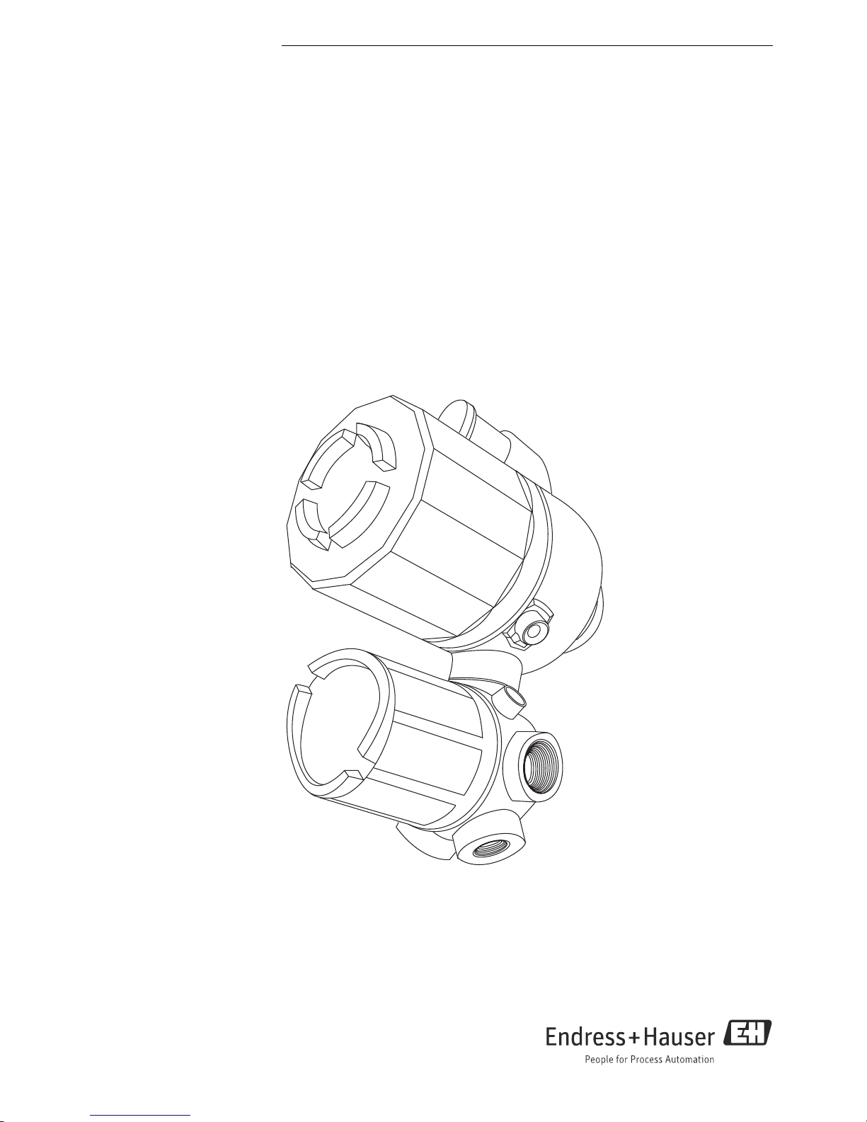
TMD1000 TMD1
Digital Transmitter
Page 2

Digital transmitter TMD1 TMD1000
2 Endress+Hauser
Table of contents
1 Safety instructions . . . . . . . . . . . . . . . . . . . . . . . . . . . . 3
1.1 Designated use . . . . . . . . . . . . . . . . . . . . . . . . . . . . . . . . . 3
1.2 Installation, commissioning, and operation . . . . . . . . . 3
1.3 Product requirements . . . . . . . . . . . . . . . . . . . . . . . . . . . 3
1.4 Operational safety . . . . . . . . . . . . . . . . . . . . . . . . . . . . . . . 4
1.5 Notes on safety conventions and symbols . . . . . . . . . . 4
1.6 Symbols for certain types of information . . . . . . . . . . . 4
2 Identification . . . . . . . . . . . . . . . . . . . . . . . . . . . . . . . . . 5
2.1 Device designation . . . . . . . . . . . . . . . . . . . . . . . . . . . . . . 5
2.2 Order information . . . . . . . . . . . . . . . . . . . . . . . . . . . . . . 8
2.3 Scope of delivery . . . . . . . . . . . . . . . . . . . . . . . . . . . . . . . 10
2.4 Registered trademarks . . . . . . . . . . . . . . . . . . . . . . . . . . 10
3 Installation . . . . . . . . . . . . . . . . . . . . . . . . . . . . . . . . . . 11
3.1 Incoming acceptance, transport, storage . . . . . . . . . . 11
3.2 Installation conditions . . . . . . . . . . . . . . . . . . . . . . . . . . 11
3.3 General view (Standard). . . . . . . . . . . . . . . . . . . . . . . . . 12
3.4 General view (Optical FFi specification) . . . . . . . . . . . 13
3.5 Installing TMD1 on float gauge (LT5) . . . . . . . . . . . . . 14
3.6 Installation TMD and LT to tank side . . . . . . . . . . . . . 16
4 Cable connection . . . . . . . . . . . . . . . . . . . . . . . . . . . . . 18
4.1 Calculation of wiring transmission distance . . . . . . . . 18
4.2 Wiring . . . . . . . . . . . . . . . . . . . . . . . . . . . . . . . . . . . . . . . . 21
5 Operation settings. . . . . . . . . . . . . . . . . . . . . . . . . . . . 23
5.1 Level adjustment operation flow . . . . . . . . . . . . . . . . . 23
6 Operations and device settings . . . . . . . . . . . . . . . . 24
6.1 HHT2 (Hand Held Terminal) . . . . . . . . . . . . . . . . . . . . 24
7 Specifications, modules and mode in HHT2 . . . . . 25
7.1 Basic specifications . . . . . . . . . . . . . . . . . . . . . . . . . . . . 25
7.2 Output1 specifications . . . . . . . . . . . . . . . . . . . . . . . . . 25
7.3 Output 2 specifications . . . . . . . . . . . . . . . . . . . . . . . . . 26
7.4 Input specifications . . . . . . . . . . . . . . . . . . . . . . . . . . . . 27
8 Maintenance . . . . . . . . . . . . . . . . . . . . . . . . . . . . . . . . 28
8.1 Exterior cleaning . . . . . . . . . . . . . . . . . . . . . . . . . . . . . . 28
8.2 Seal replacement . . . . . . . . . . . . . . . . . . . . . . . . . . . . . . 28
9 Troubleshooting . . . . . . . . . . . . . . . . . . . . . . . . . . . . . 29
9.1 Error message . . . . . . . . . . . . . . . . . . . . . . . . . . . . . . . . 29
9.2 Error confirmation . . . . . . . . . . . . . . . . . . . . . . . . . . . . . 29
9.3 Error message table . . . . . . . . . . . . . . . . . . . . . . . . . . . . 30
9.4 Malfunction diagnosis . . . . . . . . . . . . . . . . . . . . . . . . . 30
9.5 Return . . . . . . . . . . . . . . . . . . . . . . . . . . . . . . . . . . . . . . . . 31
9.6 Disposal . . . . . . . . . . . . . . . . . . . . . . . . . . . . . . . . . . . . . . 31
9.7 Software history . . . . . . . . . . . . . . . . . . . . . . . . . . . . . . . 31
10 Option . . . . . . . . . . . . . . . . . . . . . . . . . . . . . . . . . . . . . . 32
10.1 Modules . . . . . . . . . . . . . . . . . . . . . . . . . . . . . . . . . . . . . 32
10.2 Module types . . . . . . . . . . . . . . . . . . . . . . . . . . . . . . . . . 32
11 Technical data . . . . . . . . . . . . . . . . . . . . . . . . . . . . . . . 33
Table of Contents
Page 3

Digital transmitter TMD1 TMD1000
Endress+Hauser 3
1 Safety instructions
1.1 Designated use
Digital transmitter TMD1 transfers the signal relate to liquid level and liquid temperature in a tank, or
the status of power outage and malfunction via an external device and also transfers all tank data to a
receiver including that of the peripheral equipment by digital transmission system. TMD1 is used in
combination with float level gauge LT5.
1.2 Installation, commissioning, and operation
• Mounting, electrical installation, start-up, and maintenance of the instrument may only be performed by trained personnel authorized by the operator of the facility.
• Personnel must read and understand these installation instructions before performing the procedures.
• The instrument may only be operated by personnel who are authorized and trained by the operator
of the facility. All instructions in this manual must be observed.
• The installer must make sure that the measuring system is correctly wired according to the wiring
diagrams. The measuring system must be grounded.
• Observe all law and regulations applicable and valid for your country and pertaining to the opening
and repairing of electrical devices.
1.3 Product requirements
Power source
Check the voltage of the power supply before connecting it to the product. It should be the exact voltage
required for proper operation of the product.
Connection to other devices
It is possible to connect to other devices explained in this instruction. Refer to each operation instruction when connecting to devices.
Ground
Do not remove earth terminal or earth wire when the power is on.
Power cable
Use a power cable specified by our company. The product should be protectively grounded before it is
connected to a measurement object or an external control circuit.
1 Safety instructions
Page 4
Digital transmitter TMD1 TMD1000
4 Endress+Hauser
1.4 Operational safety
Hazardous area
• Use the explosion proof type for measurement in areas where explosion hazards are present.
• Devices installed in areas having explosion hazards must not be opened when the power is on.
• Strict compliance with installation instructions and - ratings, as directed in this supplementary doc-
umentation, is mandatory.
• Device maintenance and repair is restricted to meet explosion proof regulations.
• Tighten the cable gland firmly.
• Devices employed in areas having explosion hazards should be installed and wired in keeping with
explosion proof regulations.
• Ensure that all personnel are properly qualified.
• Observe the certification requirements as well as national and local regulations.
Changes or modifications other than those expressly approved by Endress+Hauser
are strictly prohibited. Unauthorized modifications can cause malfunction or damage, resulting in serious injury or death.
1.5 Notes on safety conventions and symbols
To highlight safety-relevant or alternative operating procedures in this manual, the following conventions have been used, each indicated by a corresponding symbol on the left.
1.6 Symbols for certain types of information
Symbol Meaning
A0011189-EN
DANGER!
This symbol alerts you to a dangerous situation. Failure to avoid this situation will result in
serious or fatal injury.
A0011190-EN
WARNING!
This symbol alerts you to a dangerous situation. Failure to avoid this situation can result in
serious or fatal injury.
A0011191-EN
CAUTION!
This symbol alerts you to a dangerous situation. Failure to avoid this situation can result in
minor or medium injury.
A0011192-EN
NOTICE!
This symbol contains information on procedures and other facts which do not result in
personal injury.
Symbol Meaning
A0011182
Allowed
Indicates procedures, processes or actions that are allowed.
A0011183
Recommendation
Indicates procedures, processes or actions that are recommended.
A0011184
Forbidden
Indicates procedures, processes or actions that are forbidden.
A0011193
Tip
Indicates additional information.
WARNING
DANGER
WARNING
CAUTION
NOTICE
1 Safety instructions
Page 5
Digital transmitter TMD1 TMD1000
Endress+Hauser 5
2 Identification
2.1 Device designation
2.1.1 Nameplate
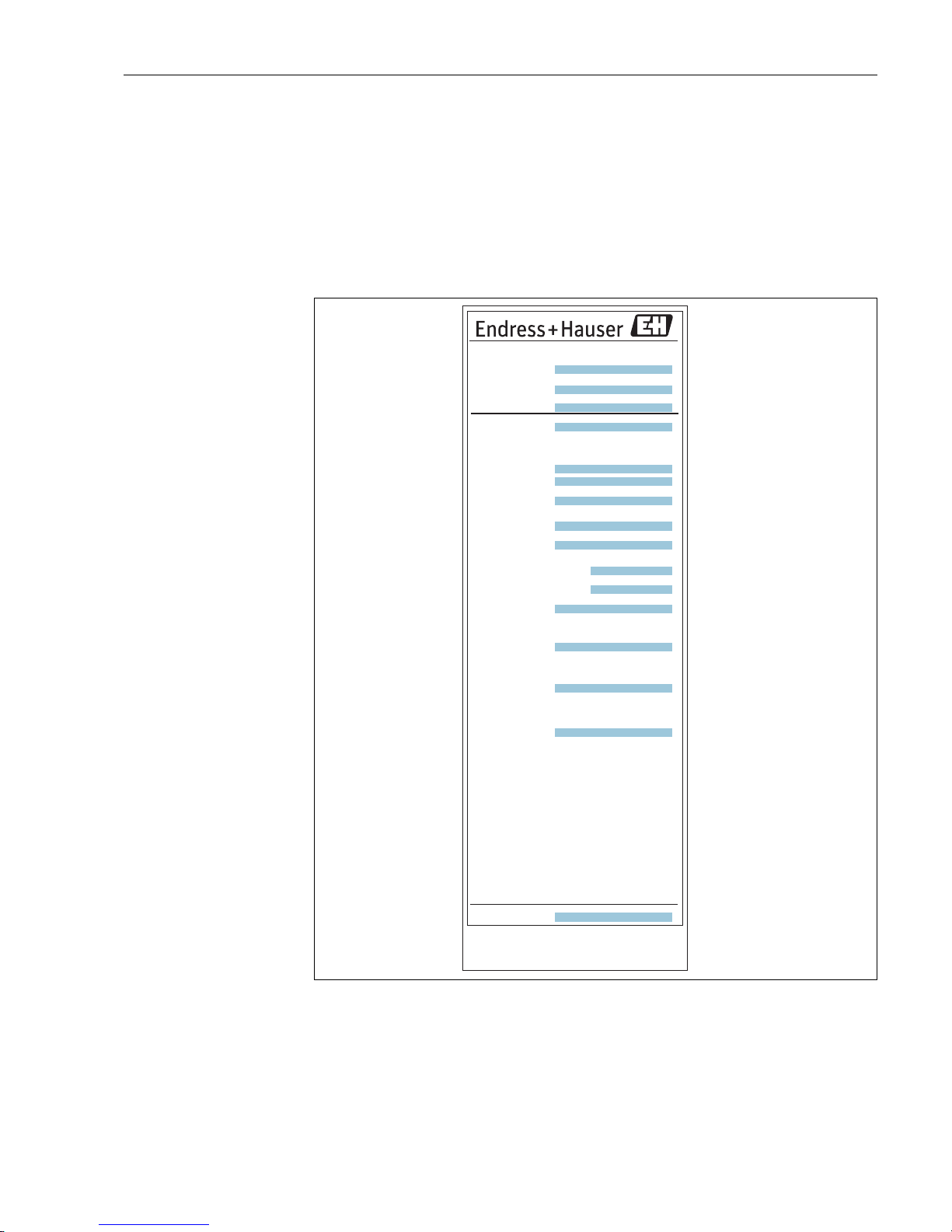
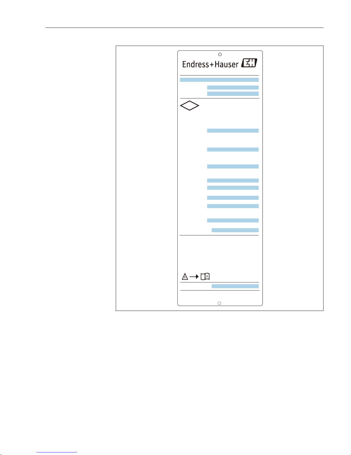
The following technical data are given on the instrument nameplate.
Figure 1: TMD1 nameplate
1. Tag number
2. Order code
3. Serial number
4. Protection class
5. Power supply
6. Power consumption
7. Transmission circuit
8. Transmission circuit
9. Analog output
ᾮ㠃ィⓎಙჾ
Level Transmitter
Serial no.
Order code
㜵⇿ᵓ㐀㸸
Protection class :
ᐃ᱁Rating
㟁※
Power Supply
㺡㺼㺎㺞ఏ㏦ᅇ㊰
Transmission
circui t
㺏㺣㺹㺖㺼ฟຊ
$QDORJRXWSXW
ධຊಙྕ
㺏㺣㺹㺖㺼
Input signal Analog
ᗘ
Tem p
᥋Ⅼධຊᅇ㊰
Contact input
(୍᥋Ⅼᐜ㔞)
(1 co nt act )
᥋Ⅼฟຊᅇ㊰
Contact output
(一接点容量)
(1 co nt act )
እ㒊⾲♧ฟຊ
Display output
࿘ᅖ ᗘ-20 Υ㹼 +60 Υ
Ambient temp
〇㐀ᖺ᭶᪥
Manufacturing date
Wiring code :
㆙࿌㸸
⇿Ⓨᛶ㞺ᅖẼࡀᏑᅾࡋ࡞࠸ࡇࢆ☜ㄆࡋ࡚ࡽᐜჾࢆ㛤
ࡅ࡚ࡃࡔࡉ࠸ࠋ
㏻㟁≧ែ࡛ࡣࢆ㛤ࡅ࡞࠸࡛ࡃࡔࡉ࠸ࠋ
HHT᥋⥆௨እࡣග㺘㺦㺖㺞ࡢࢆ㛤ࡅ࡞࠸࡛ࡃࡔࡉ࠸ࠋ
⪏⇕ ᗘΥ௨ୖࡢ㺗㺎㺪㺼㺷ࢆ⏝ࡋ࡚ࡃࡔࡉ࠸ࠋ
Warning:
Before opening the cover, to confirm that there is
no explosive atmosphere.
Do not open the cover when energized.
Do not open the cover of the optical connector
except when HHT will be connected.
Use supply wires suitable for 65℃minimum.
NP-2660-1
ỺὅἛἾἋἡỸἈὊޛషఇࡸ˟ᅈ
Yamanashi 406-0846
Made in Japan
Endress+Hauser Yamanashi Co.,Ltd.
IP65
1
2
3
4
5
6
7
8
9
12
13
14
10
11
15
16
2 Identification
Page 6
Digital transmitter TMD1 TMD1000
6 Endress+Hauser
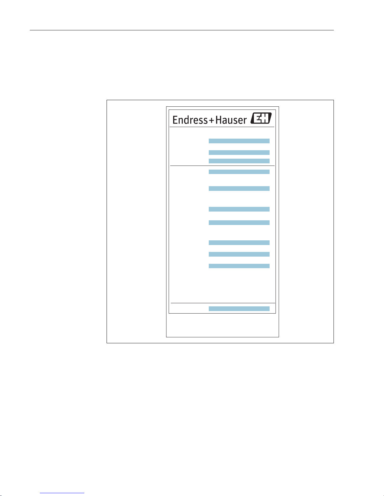
10. Input signal (Analog)
11. Input signal (Temperature)
12. Contact input circuit
13. Contact output circuit
14. Display output
15. Manufacturing date
16. Wiring code
Figure 2: TMD1 with Optical FFi Specification
1. Old model code
2. Order code
3. Serial number
4. Explosion proof model
5. Protection class
6. Power supply
7. Power consumption
8. Input signal
9. Contact input
10. Contact output
11. Wiring code
ᾮ㠃ィⓎಙჾLevel Transmitter
㆙࿌㸸㏻㟁≧ែ࡛ࡣࢆ㛤ࡅ࡞࠸࡛ࡃࡔࡉ࠸ࠋ
Warning: Do not open the cover when energized.
㜵⇿ᆺᘧ㸸
Explosion proof model :
㜵⇿ᵓ㐀㸸
Protection class :
Serial no.
Order code
NP-2033-3
Wiring code :
ỺὅἛἾἋἡỸἈὊޛషఇࡸ˟ᅈ
Yamanashi 406-0846
ᐃ᱁5DWLQJ㸸
㟁※㟁ᅽ㸸
ࠉ ࢹ࣮ࢱ࣮ఏ㏦ᅇ㊰DC 48 V 500 mA max.
Transmission circuit :
ධຊಙྕ
Input signal :
᥋Ⅼධຊ
Contact input :
᥋Ⅼฟຊࠉ
Contact output :
࿘ᅖ ᗘࠉ-10 Υ㹼 +60 Υ
$PELHQWWHPSHUDWXUH
Power Supply :
IP65
Made in Japan
Endress+Hauser Yamanashi Co.,Ltd.
1
2
3
4
5
6
7
8
9
10
11
2 Identification2 Identification
Page 7
Digital transmitter TMD1 TMD1000
Endress+Hauser 7
Figure 3: Nameplate for FM approval
1. Required contents by a customer (e.g. Tag No.)
2. Order code
3. Serial number
4. Rating
5. Data
6. Analog output
7. Analog input
8. Temperature input
9. Contact input
10. Contact output
11. Display output
12. Manufacturing date
13. Wiring code
Digital Transmitter TMD1
Order code
Serial no.
Rating:
Power Supply
Data
communication
Analog output
Analog input
Temp. input
(RTD input)
Contact input
(1 contact c ap.)
Contact output
(1 contact c ap.)
Display output
Manufacturing date
Warning:
- Before opening the cover, to confirm that there is
no explosive atmosphere.
- Do not open the cover when energized.
- Do not open the cover of the optical connector
except when HHT will be connected.
- Using the cable that has heat resistance more
than 65Υ.
NP-2682
Yamanashi 406-0846
Made in Japan
Endress+Hauser Yamanashi Co.,Ltd.
XA01089G
BA00427G
Wiring code :
APPROVED
FM
XP Class I, Div.1, Gp. C, D, T4
Cert. No. FM16US0252X
Ambient temperature: -20 㹼 +60Υ
Type 4X, IP65
1
2
3
4
5
6
7
8
9
10
11
12
13
2 Identification
Page 8
Digital transmitter TMD1 TMD1000
8 Endress+Hauser
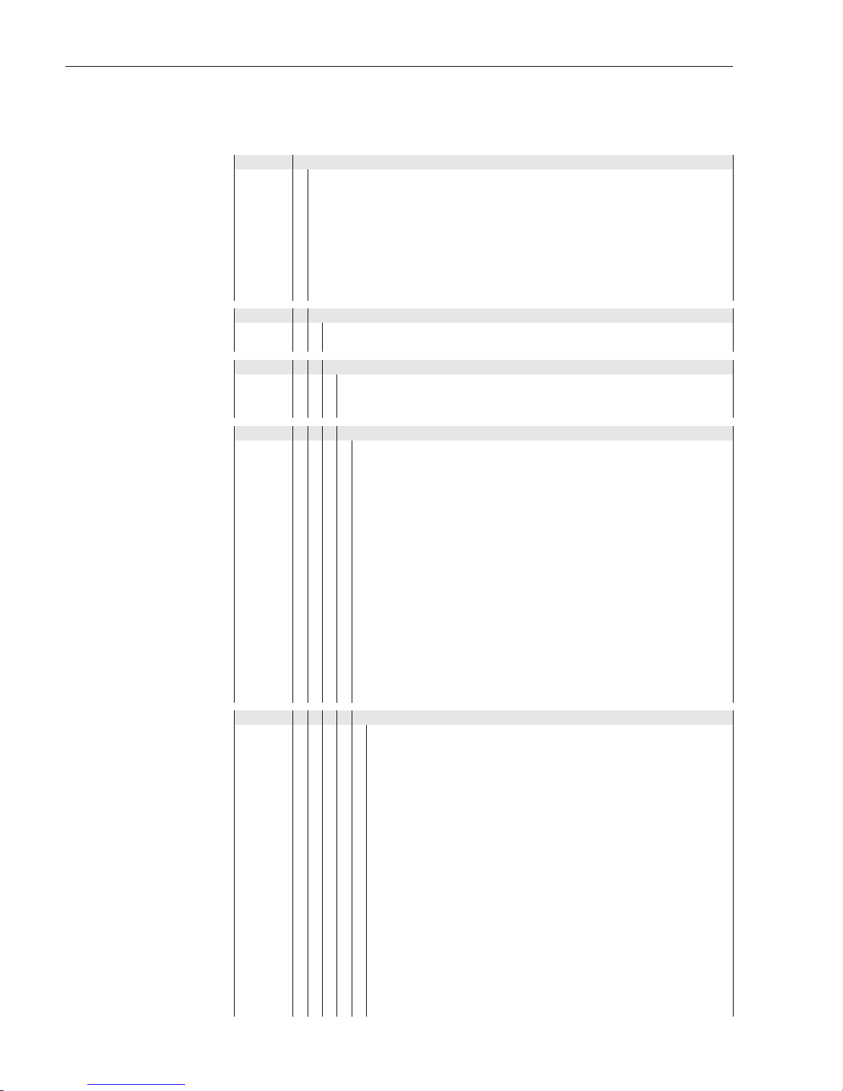
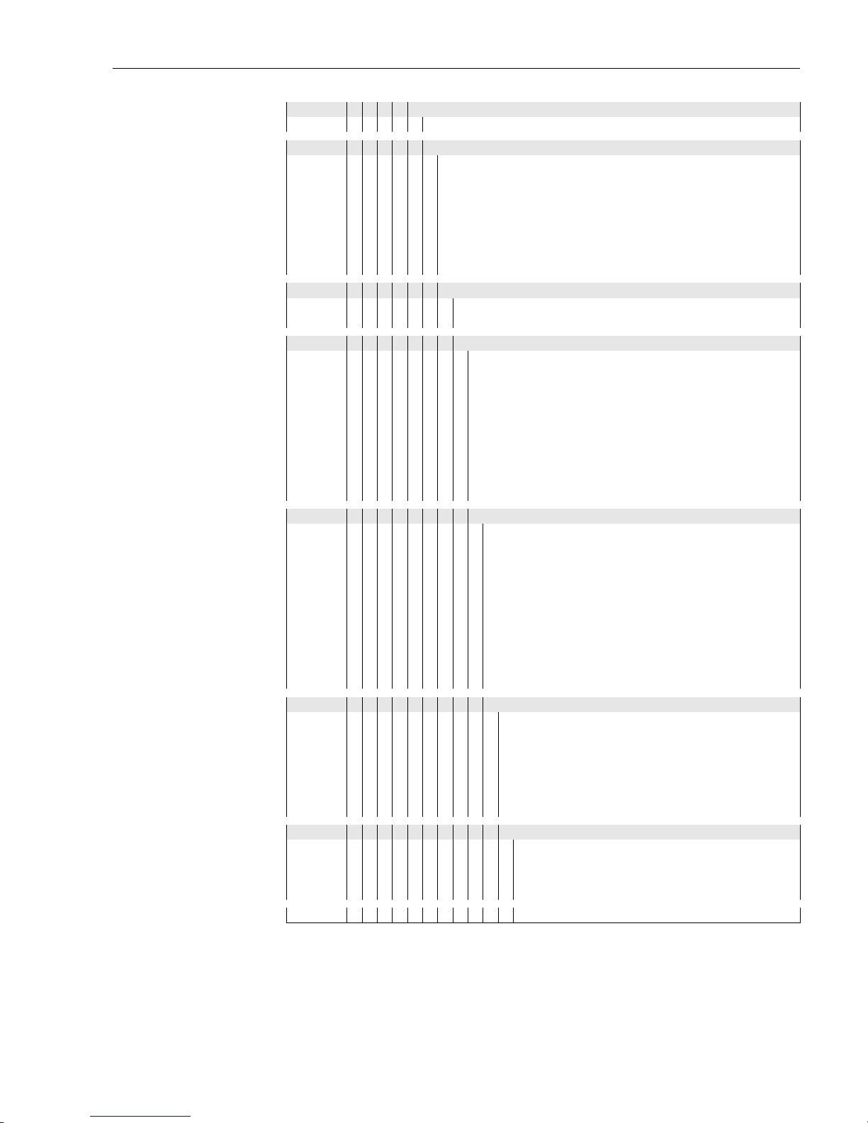
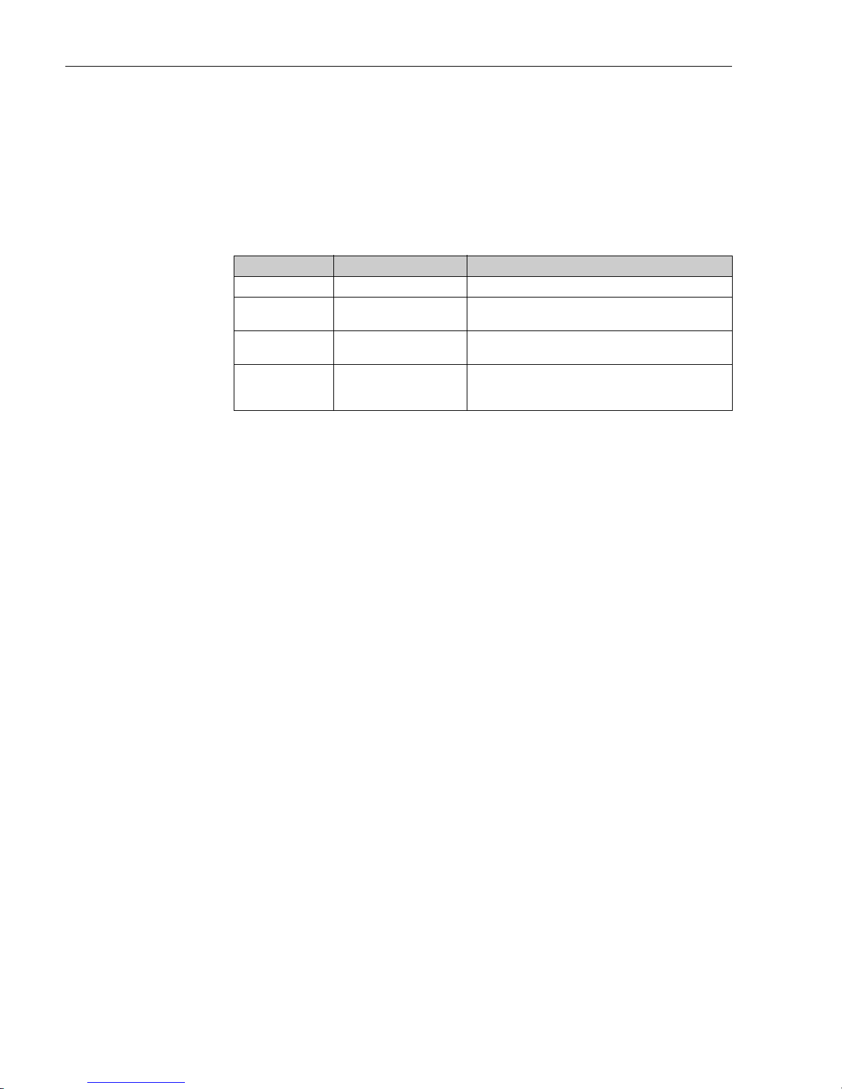
2.2 Order information
010 Output 1
0 Not selected
14-20 mA
22-way 2-wire (MDP protocol)
3BCD parallel
4 Sakura code parallel
52-way 2-wire (MIC, BBB protocol)
6 2-way 2-wire (V1 protocol)
7 Optical FFi
9 Special version, TSP-no. to be spec.
020 Function:
B HART input (NMT5xx, NRF560)
9 Special version, TSP-no. to be spec.
030 Approval:
0 Weather proof IP65
4 Exd IIB T4, TIIS
5 FM XP Cl.I Div.1 Gr.C-D, AEx d IIB T4
040 Output 2:
0 Not selected
14-20 mA
2 4 x alarm (open collector)
3 Monitor DRM
4 2 x gauge operation command
5 2 x gauge operation command, 6x outer equipment operation command
6 8 x outer equipment operation command
A4-20 mA, 4 x alarm (open collector)
B 4-20 mA, monitor DRM
C 4x alarm (open collector), monitor DRM
D 4-20 mA, 4 x alarm (open collector), monitor DRM
E 4-20 mA, 2 x gauge operation command
F 2 x gauge operation command, monitor DRM
G 4 x alarm (relay)
H 4-20 mA, 4 x alarm (relay)
J 4 x alarm (relay), monitor DRM
K 4-20 mA, 4 x alarm (relay), monitor DRM
Y Special version, TSP-no. to be spec.
050 Input:
0Not used
14-20 mA
24 x status
3 1 x spot temperature Pt100/JPt100
4 3 x spot temperature Pt100/JPt100
5 Multi element average temperature
6 Multi spot average temperature
A 4-20 mA, 1 x spot temperature Pt100/JPt100
B 4-20 mA, 3 x point spot temperature Pt100/JPt100
C 4-20 mA, multi element average temperature
D 4-20 mA, multi spot average temperature Pt100/JPt100
E 4 x status, 1 x spot temperature Pt100/JPt100
F 4 x status, 3 x spot temperature Pt100/JPt100
G 4 x status, multi element average temperature
H 4 x status, multi spot average temperature
J4-20 mA, 4 x status
K 4-20 mA, 4 x status, 1 x spot temperature Pt100/JPt100
L 4-20 mA, 4 x status, 3 x spot temperature Pt100/JPt100
M 4-20 mA, multi element average temperature, 4 x status
N 4-20 mA, multi spot average temperature, 4 x status
2 Identification
Page 9
Digital transmitter TMD1 TMD1000
Endress+Hauser 9
Y Special version, TSP-no. to be spec.
060 Power Supply:
C Loop powered
B 20-32VDC
5 60VAC, 50/60Hz
1 100VAC, 50/60Hz
2 110VAC, 50/60Hz
3 200VAC, 50/60Hz
4 220VAC, 50/60Hz
9 Special version, TSP-no. to be spec.
070 Color:
1Blue + white
9 Special version, TSP-no. to be spec.
080 Cable Entry:
0 A: PF(G)1-1/2, B: PF(G)3/4, C: PF(G)1, D: PF(G)1
H 2 x thread G1 EXPC-28B, 2 x blind plug see additional spec.
J 3 x thread G1 EXPC-28B, 1 x blind plug see additional spec.
K 4 x thread G1 EXPC-28B see additional spec.
L 2 x thread G3/4 EXPC-22B,2 x blind plug see additional spec.
M 3 x thread G3/4 EXPC-22B,1 x blind plug see additional spec.
N 4 x thread G3/4 EXPC-22B see additional spec.
P4 x thread NPT 1
Q4 x thread NPT 3/4
9 Special version, TSP-no. to be spec.
090 Communication:
0Not used
2 2-way 2-wire (MIC, BBB protocol)
3 2-way 2-wire (MDP protocol)
4 2-way 2-wire (V1 protocol)
A Emitter common
B Collector common
F Store box (Optical FFi)
H M42 x P1.5 (Optical FFi)
J 4-20 mA HART
KMODBUS RS485
9 Special version, TSP-no. to be spec.
100 Temperature Input:
0Not used
1 Pt100, JIS=IEC, -50...+200°C
2 Pt100, JIS=IEC, +70...+350°C
3 JPt100, JIS, -50...+200°C
4 JPt100, JIS, +70...+350°C
5NMT
9 Special version, TSP-no. to be spec.
110 Application:
3 LT11/LT12/LT31/LT32
4 LT14/LT16/LT34/LT36
5 LTC2230/LTC2240
9 Special version, TSP-no. to be spec.
TMD1- Complete product designation
050 Input:
2 Identification
Page 10
Digital transmitter TMD1 TMD1000
10 Endress+Hauser
2.3 Scope of delivery
It is extremely important to follow the instructions concerning the unpacking, transportation and storage of measuring instruments provided in the chapter “Incoming acceptance, transportation, storage”.
The scope of delivery consists of:
• Assembled instrument
• Documents
Documents list for TMD1
2.4 Registered trademarks
HART®
Registered trademark of HART Communication Foundation, Austin, USA
Document No. Type of documents Descriptions
BA00427G Operating Instructions Installation, wiring, and maintenance
BA00428G
Module Setting/Adjustment
Instructions
Installation, Operations, Adjustment, Descriptions of
errors
BA00429G
HHT2 Operating Instructions
Operations, commissioning for TMD1
XA01073G Safety Instructions
Device versions approved for use in explosion hazardous
areas; nameplate specifies, which of these documents is
relevant for your instrument version
2 Identification
Page 11
Digital transmitter TMD1 TMD1000
Endress+Hauser 11
3Installation
3.1 Incoming acceptance, transport, storage
3.1.1 Incoming acceptance
Check the packing and contents for any signs of damage.
Check the shipment, and make sure that nothing is missing and that the items match your order.
3.1.2 Transport
• Follow the safety instructions and conditions of transportation for instruments in excess of 18kg
(40 lbs.).
• Do not lift the measuring instrument by its housing during transportation.
3.1.3 Storage
Pack the measuring instrument so that it is protected against impacts during storage and transportation.
The original packing material provides the optimum protection for this.
The allowed storage temperature is -20°C to +60°C (-4°F to +140°F)
3.2 Installation conditions
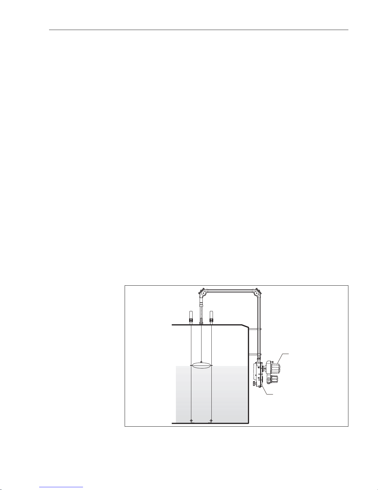
Digital Transmitter TMD1 is designed to be installed on the rear of a level gauge and placed at outside
the tank as shown below. The unit (level gauge and transmitter) is primarily employed in measurement
level; particularly for crude or other oil in refineries and storage tanks. Other applications may include
acid, alkaline fluid and fat products in chemical industry storage tanks.
Figure 4: TMD1 installation
1. Digital transmitter TMD1
2. Float level gauge LT5
1
2
3 Installation
Page 12
Digital transmitter TMD1 TMD1000
12 Endress+Hauser
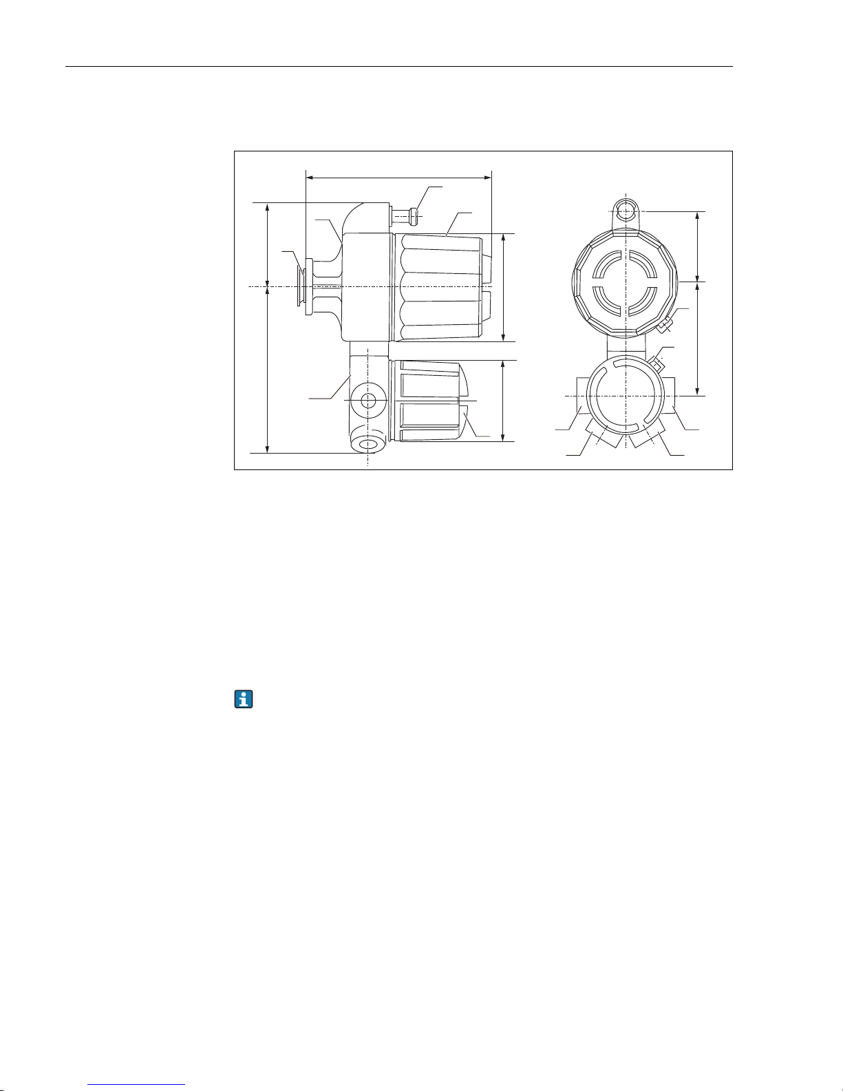
3.3 General view (Standard)
Figure 5: General view, Unit: mm (in)
A Cable gland: position of cable entry A, B, C, D
B Cable gland: position of cable entry A, B, C, D
C Cable gland: position of cable entry A, B, C, D1
D Cable gland: position of cable entry A, B, C, D
a 325 mm (12.79 in) for all spec., excluding FM spec./335 mm (13.19 in) for FM spec.
1. Coupling (Material: ADC6/Quantity: 1)
2. Electrical housing (Material: AC4C-T6/Quantity: 1)
3. Cover of Electrical housing (Material: AC4C-T6/Quantity: 1)
4. Terminal box (Material: ADC12/Quantity: 1)
5. Locking (Material: ADC6/Quantity: 1)
6. Connection of Hand Held Terminal (HHT2)
7. Terminal box cover (AC4C-T6/Quantity: 1)
The position of the cable entry (optional: H, J, K, L, M, N) in order information 080 must be specified by a customer.
140 (5.51)
˓
˓
a
AB
CD
1
4
5
5
3 Installation
Page 13
Digital transmitter TMD1 TMD1000
Endress+Hauser 13
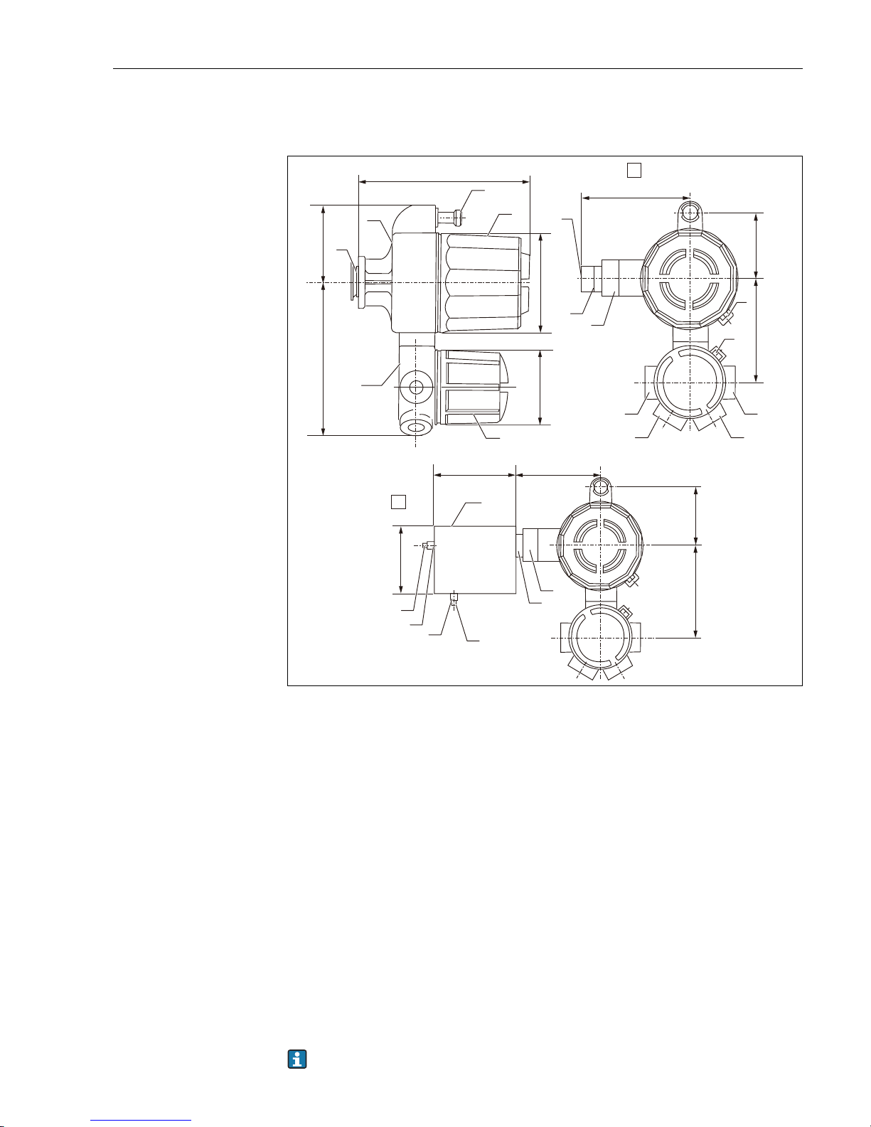
3.4 General view (Optical FFi specification)
Figure 6: General view
A Cable gland: position of cable entry A, B, C, D
B Cable gland: position of cable entry A, B, C, D
C Cable gland: position of cable entry A, B, C, D1
D Cable gland: position of cable entry A, B, C, D
F Terminal box type
H M42 x P1.5 slide coupling type
a 325 mm (12.79 in) for all spec., excluding FM spec./335 mm (13.19 in) for FM spec.
1. Coupling (Material: ADC6/Quantity: 1)
2. Electrical housing (Material: AC4C-T6/Quantity: 1)
3. Cover of electrical housing (Material: AC4C-T6/Quantity: 1)
4. Terminal box (Material: ADC12/Quantity: 1)
5. Locking (Material: ADC6/Quantity: 1)
6. Connection of Hand Held Terminal (HHT2)
7. Optical unit adapter (Material: SUS304/Quantity: 1)
8. Optical unit 6D (Quantity: 1)
9. Connection box (Material: Aluminum/Quantity: 1)
10. Lead-in cable (Rc1/2) (Material: Ferrous casting/Quantity: 1)
11. Blind plug (Material: FCMB310/Quantity: 1)
12. FC inlet connection (M42 x P1.5/Quantity: 1)
13. Terminal box cover (AC4C-T6/Quantity: 1)
The position of the cable entry (optional: H, J, K, L, M, N) in order information 080 must be specified by a customer.
118 (4.65) 191 (7.52)
118 (4.65) 191 (7.52)
AB
CD
140 (5.51)
˓ ˓
280 (11.02)
a
1
2
12
6
4
5
5
7
8
8
180 (7.09)
200 (7.87) 159 (6.26)
150 (5.91)
10
10
11
11
9
7
H
F
3 Installation
Page 14
Digital transmitter TMD1 TMD1000
14 Endress+Hauser
3.5 Installing TMD1 on float gauge (LT5)
Digital transmitter TMD1 is designed to be installed on the rear of the float gauge head by using a
flange.
Installation procedure
Stud bolt, nut, washer, and coupling are supplied with TMD1 in a plastic bag.
1. Insert the stud bolt in the rear cover of the float gauge.
2. Make sure that the coupling on TMD is secure when installing on low pressure float gauges.
• Make sure that coupling on both TMD and float gauge is secure when installing on medium or
high pressure float gauges.
This completes installation procedure.
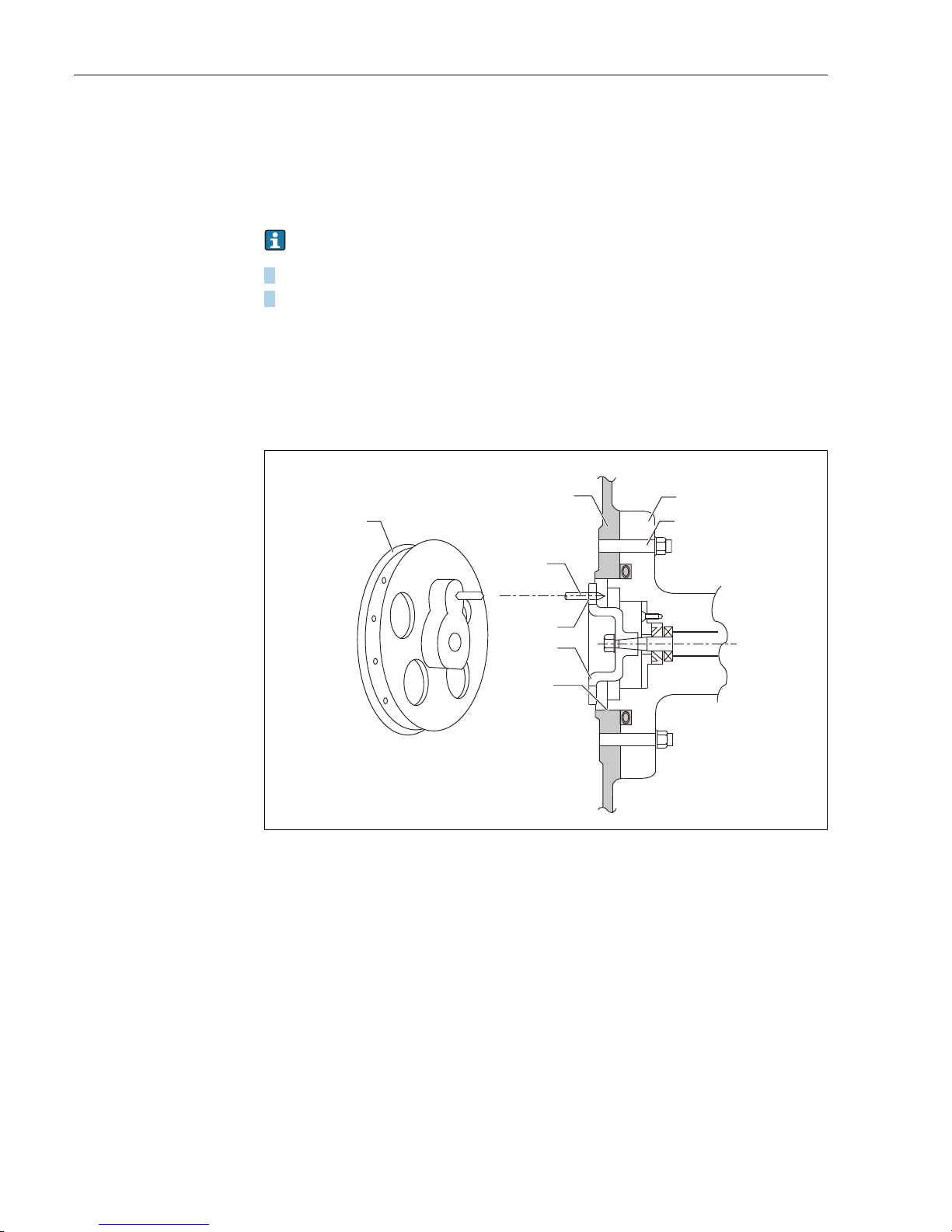
3.5.1 Coupling installation
Figure 7: Coupling installation for low pressure float gauge
a Be careful to install this part.
b Ensure installation of this part.
1. Transmitter
2. Stud bolt
3. Float level gauge
4. Sprocket pin
5. Coupling
6. Sprocket
6
1
2
3
4
a
5
b
3 Installation
Page 15
Digital transmitter TMD1 TMD1000
Endress+Hauser 15
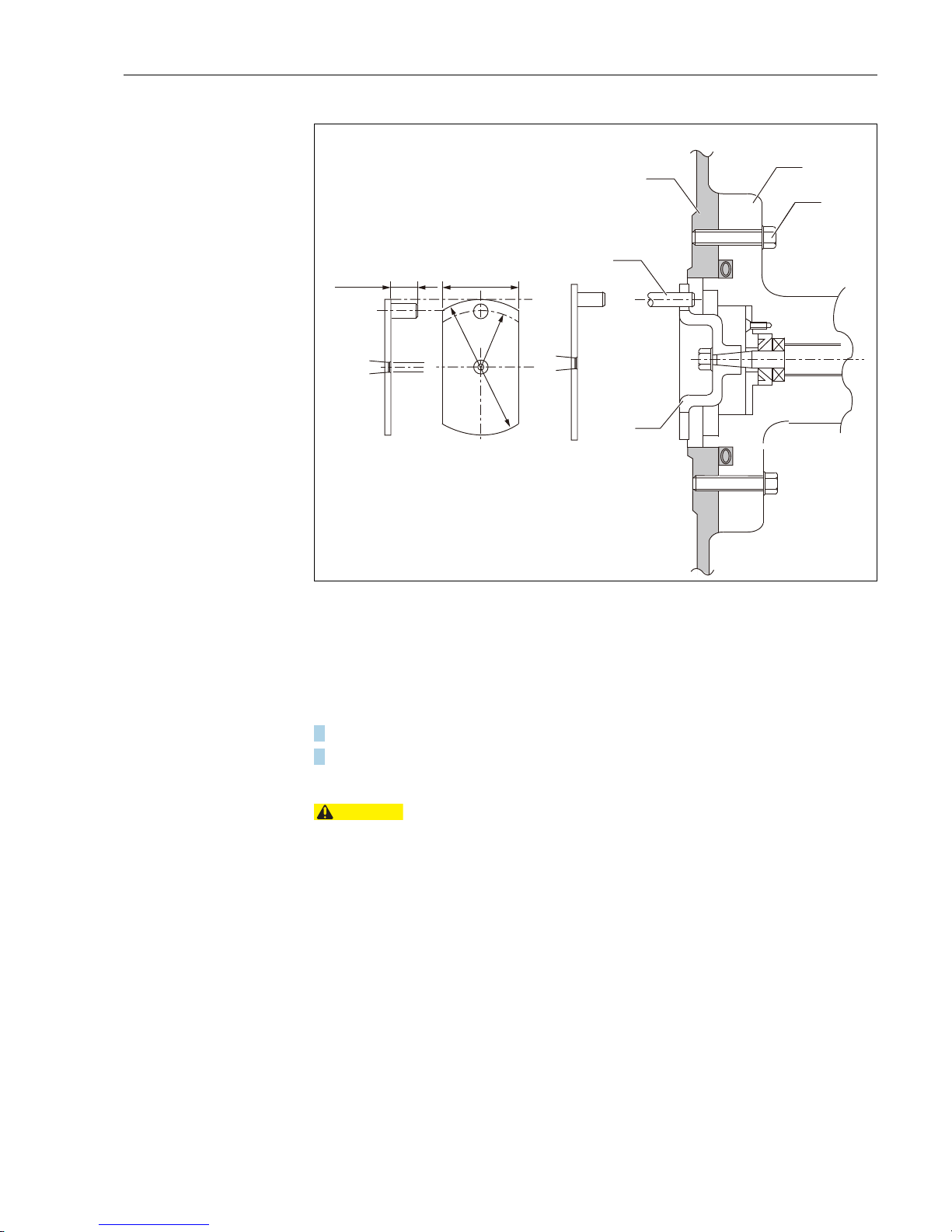
Figure 8: Coupling installation for medium and high pressure float gauge
1. Transmitter
2. Stud bolt
3. Level gauge
4. Coupling pin
5. Coupling (Transmitter)
Installation procedure
1. Remove the TMD rear cover.
2. Install TMD in float gauge while engaging coupling groove with coupling pin.
This completes installation procedure.
• If the coupling groove and the pin positions are not aligned, the installation surface between LT and
TMD will rise and not match with the position. Do not install the coupling using excessive force.
Check coupling position and reinstall TMD, if needed.
• When the professional installation and adjustment service of Endress+Hauser are required, all procedures, including unpacking, are conducted by our service technician.
30 (1.18)
10 (0.39)
1
2
3
4
5
R20
(0.79)
Ø50 (1.97)
CAUTION
3 Installation
Page 16
Digital transmitter TMD1 TMD1000
16 Endress+Hauser
3.6 Installation TMD and LT to tank side
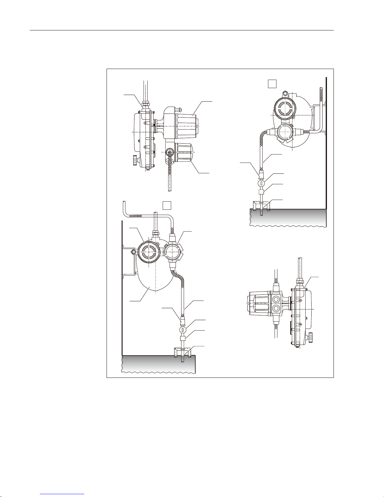
Figure 9: Tank installation (Standard)
A Standard installation
B Special installation when the flexible fitting [4] cannot be mounted in the standard position (Not recom-
mended due to high risk of rain water).
1. Float level gauge
2. Electrical housing of TMD1
3. Terminal box of TMD1
4. Flexible fitting
5. Cable gland or cable conduit
6. Tumbler switch
7. Flexible fitting
8. Thick steel conduit tube
1
2
3
4
5
5
6
7
8
4
6
7
8
1
2
3
1
A
B
3 Installation
Page 17
Digital transmitter TMD1 TMD1000
Endress+Hauser 17
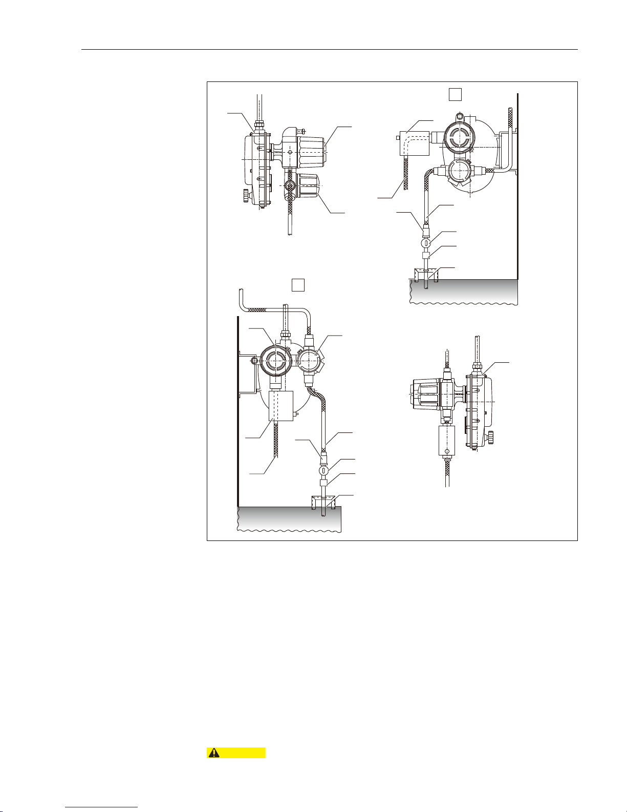
Figure 10: Tank installation (FFi Specification)
A Standard installation
B Special installation when the flexible fitting [4] cannot be mounted in the standard position (Not recom-
mended due to high risk of rain water).
1. Float level gauge
2. Electrical housing of TMD1
3. Terminal box of TMD1
4. Connection box for FFi optical communication
5. Flexible fitting for optical fiber
6. Flexible fitting
7. Cable gland or cable conduit
8. Tumbler switch
9. Flexible fitting
10. Thick steel conduit tube
3.6.1 HHT2 (Hand Held Terminal)
Always make data setting using HHT2 during operations (conditioning setting). If
conditions are not set, proper readings cannot be obtained.
1
2
3
4
5
6
7
8
9
10
1
2
5
6
7
8
9
10
4
3
A
B
CAUTION
3 Installation
Page 18
Digital transmitter TMD1 TMD1000
18 Endress+Hauser
4 Cable connection
For TMD cable connections, the terminal configuration and internal wiring vary depending
on specifications. Be sure to confirm delivery specifications to prevent incorrect wiring.
Select cables so that TMD terminal power supply can reach to a nominal voltage of 90% or
more in the following cases.
4.1 Calculation of wiring transmission distance
Calculation sample
1. Calculation object is to find resistance between circuits and electrical capacity limits.
• One-way resistance: Max. 120 Ω
• Maximum capacity between circuits: 30 μF
2. Maximum capacity of cable resistance and between circuits (see the following table).
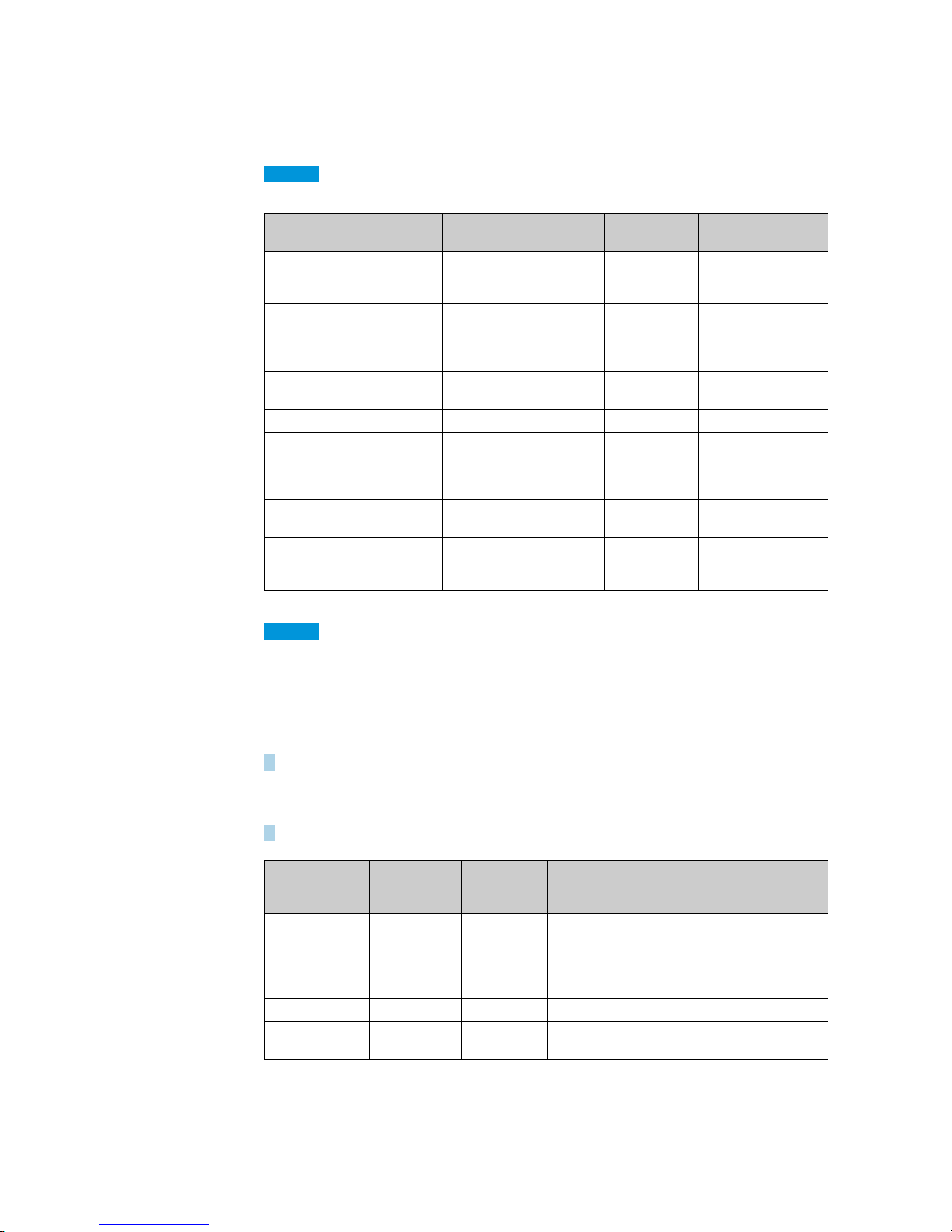
I/O signal Recommended cable type
Recommended
cable
Remarks
Power supply
PVC, PE 600V dielectric
strength voltage cable with
shield or equivalent
CVV-S
Define core area based
on the power consumption 20VAC.
Digital signal
(2-way 2-wire transmission,
DRM9700 communication)
Twisted pair cable for digital
communication
CPEV
KPEV
The data can be transferred in a range of up
to 6km with CPEV Ø1.2
cable.
(NMT, NRF communication)
Twisted pair cable with shield
for digital communication
CPEV-S
KPEV-S
I/O 4 to 20 mA PVC or PE dielectric cable CVV-S
Output contact PVC or PE dielectric cable CVV-S
Use contact output max.
voltage rating: 30DCV
and contact input:
12DCV.
RCV, RCS/NC
Temperature input (PT 100
Ω)
Standard control cable
(conduit, flexible tube) Ω
IV Cable
Use CCV-S cable if cable
conduit is not employed.
BCD, Sakura code parallel output
Multicore twisted pair cable or
equivalent
CPEV-S
KPEV-S
If level transmission is
19999mm, 18 cores (9
pairs) are required.
Cables
Conductor
resistance
(
Ω/km)
Electric
capacity
(μF/km)
Max.
transmission
distance (Km)
Remarks
CPEV, CPEE Ø0.9 Max. 30 Max. 0.05 4 Calculation based on 30
Ω
KMPEV. KPEV-S
KMPEE 0.9 mm
2
Max. 21.5 0.05 5.58 Calculation based on 21.5 Ω
CPEV Ø1.2 16.5 0.05 6 Calculation based on 0.05μF
CPEV (T) Ø0.9 Max. 30 0.06 μF 4 Calculation based on 30 Ω
CVV2 mm2 (CEE) 9.5
0.09
(0.06)
3.3 (5)
Calculation based on
0.09
(0.06) μF
NOTICE
NOTICE
4 Cable connection
Page 19
Digital transmitter TMD1 TMD1000
Endress+Hauser 19
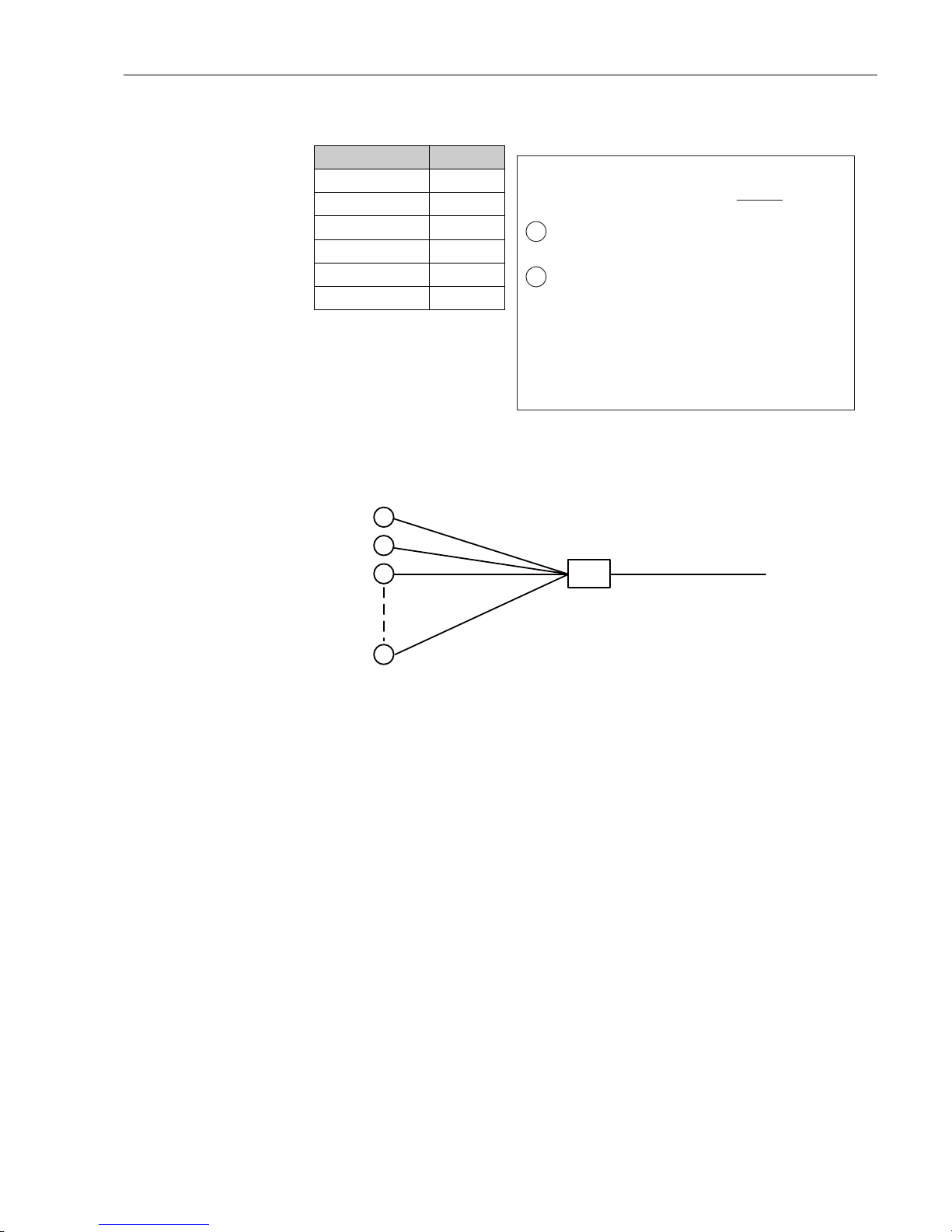
In case of TMD1 with 100VAC
Power supply cable data
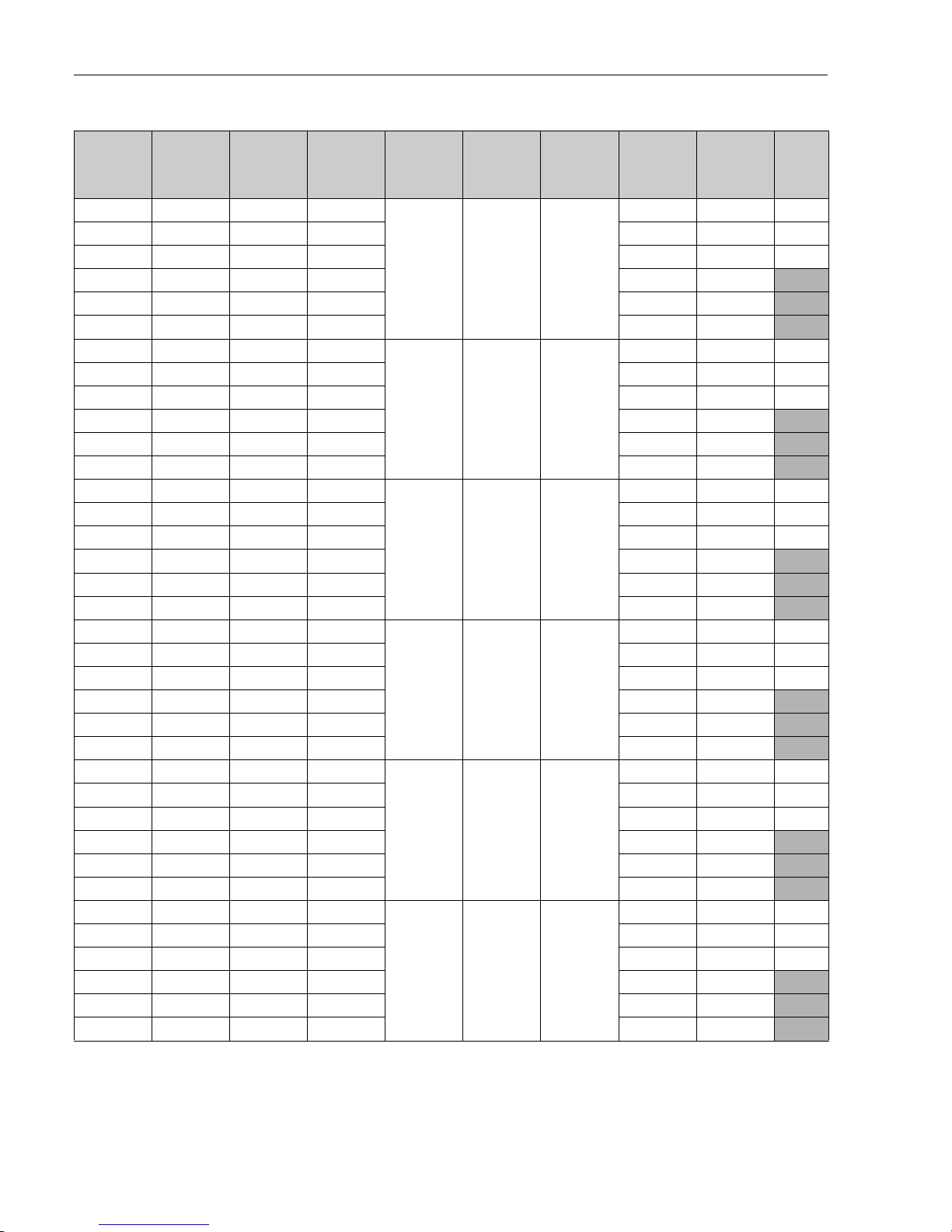
The following table shows values outcomes when assigning the following values to the formula above.
• Cable 1 length: 100 m
• Cable 2 length: 2 km
Cross-section area Ω/1km
1.25 mm
2
14.7 Ω
2.0 mm
2
9.7 Ω
3.5 mm
2
5.3 Ω
5.5 mm
2
3.4 Ω
8 mm
2
2.3 Ω
14 mm
2
1.3 Ω
Voltage drop calculation formula
Supply current for one transmitter: = 0.1 A
100 V
10 VA
1
Voltage drops by cable 1:
10 transmitters x 0.1 A x Rʹ = 1 Rʹ (V)
2
Voltage drops by cable 2:
1 transmitter x 0.1 A x Rʺ
5ʺ (V)
Maximum allowable voltage drops for cable 1 and 2:
From allowable power fluctuation of power supply -10 %
100 (V) x 10 % = 10 (V)
The result is:
10 (V) > 1 Rʹ (V) + 0.1 Rʺ (V)
JB
#2
#3
#10
Power supply
Cable 2
Distance Lʺ (Km)
Cable 1
Distance Lʹ (Km)
5ʹ
5ʺ
TMD1
#1
4 Cable connection
Page 20
Digital transmitter TMD1 TMD1000
20 Endress+Hauser
Cable 1
Cross-sec-
tion area
(mm
2
)
Ω/1km Ω/2km
Cable 2
Voltage
drops (V)
Cable 2
Cross-sec-
tion (mm
2
)
Ω/100mm
Cable 2
voltage
drops (V)
Cable1 and
2 voltage
drops (V)
TMD1 ter-
minal volt-
age (V)
Result
1.25 14.70 29.40 29.40
1.25 2.94 0.294
29.694 70.306 NG
2.00 9.50 19.00 19.00 19.294 80.706 NG
3.50 5.30 10.60 10.60 10.894 89.106 NG
5.50 3.40 6.80 6.80 7.094 92.906
OK
8.00 2.30 4.60 4.60 4.894 95.106
OK
14.00 1.30 2.60 2.60 2.894 97.106 OK
1.25 14.70 29.40 29.40
21.90.19
29.59 70.41 NG
2.00 9.50 19.00 19.00 19.19 80.81 NG
3.50 5.30 10.60 10.60 10.79 89.21 NG
5.50 3.40 6.80 6.80 6.99 93.01
OK
8.00 2.30 4.60 4.60 4.79 95.21
OK
14.00 1.30 2.60 2.60 2.79 97.21 OK
1.25 14.70 29.40 29.40
3.5 1.06 0.106
29.506 70.494 NG
2.00 9.50 19.00 19.00 19.106 80.894 NG
3.50 5.30 10.60 10.60 10.706 89.294 NG
5.50 3.40 6.80 6.80 6.906 93.094
OK
8.00 2.30 4.60 4.60 4.706 95.294
OK
14.00 1.30 2.60 2.60 2.706 97.294
OK
1.25 14.70 29.40 29.40
5.5 0.68 0.068
29.468 70.532 NG
2.00 9.50 19.00 19.00 19.068 80.932 NG
3.50 5.30 10.60 10.60 10.668 89.332 NG
5.50 3.40 6.80 6.80 6.868 93.132
OK
8.00 2.30 4.60 4.60 4.668 95.332
OK
14.00 1.30 2.60 2.60 2.668 97.332
OK
1.25 14.70 29.40 29.40
8 0.46 0.046
29.446 70.554 NG
2.00 9.50 19.00 19.00 19.046 80.954 NG
3.50 5.30 10.60 10.60 10.646 89.354 NG
5.50 3.40 6.80 6.80 6.846 93.154
OK
8.00 2.30 4.60 4.60 4.646 95.354
OK
14.00 1.30 2.60 2.60 2.646 97.354
OK
1.25 14.70 29.40 29.40
14 0.26 0.026
29.426 70.574 NG
2.00 9.50 19.00 19.00 19.026 80.974 NG
3.50 5.30 10.60 10.60 10.626 89.374 NG
5.50 3.40 6.80 6.80 6.826 93.174
OK
8.00 2.30 4.60 4.60 4.626 95.374
OK
14.00 1.30 2.60 2.60 2.626 97.374
OK
4 Cable connection
Page 21
Digital transmitter TMD1 TMD1000
Endress+Hauser 21
4.2 Wiring
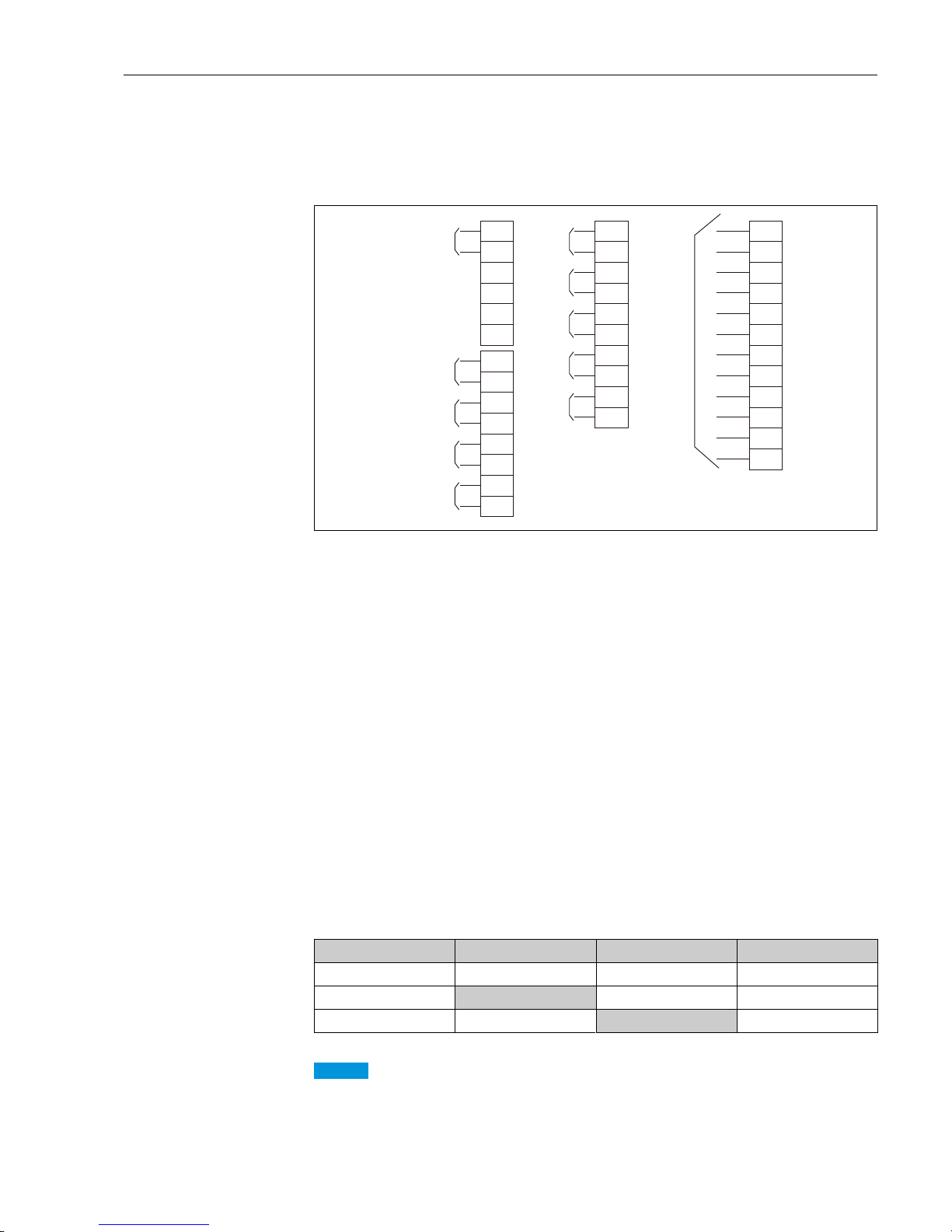
The following is a typical TMD1 terminal connection diagram. For wiring cables, refer to delivery specifications.
Figure 11: TMD1 Terminal table (e.g. TMD1 B-2)
AAC power supply
B 2-way 2-wire transmission
C DC 4 to 20 mA output
D DRM9700 output
E DC 4 to 20 mA input
F HART signal (see NOTICE.)
GAlarm output 1
HAlarm output 2
IAlarm output 3
JAlarm output 4
K Average temperature input
A1 Spot1
A2 Spot1
A3 Spot1
A4 Spot2
A5 Spot2
A6 Spot2
A7 Spot3
A8 Spot3
A9 Spot3
Contact switch
Temperature input connection may be either HART signal or RTD input. Both connection
types cannot be utilized at one time.
Operation SW1 (Terminal No.4) SW2 (Terminal No.5) SW3 (Terminal No.6)
Level measurement OFF OFF OFF
Hoist up
ON OFF OFF
Stop OFF
ON OFF
1
2
3
4
5
6
7
8
9
10
11
12
13
14
A
+
-
+
-
+
-
+
-
B
C
D
E
15
16
17
18
19
20
21
22
23
24
+
-
+
-
+
-
+
-
+
-
F
G
H
I
J
25
26
27
28
29
30
31
32
33
34
35
36
(B)
(b)
(A1)
(A2)
(A3)
(A4)
(A5)
(A6)
(A7)
(A8)
(A9)
(A10)
K
NOTICE
4 Cable connection
Page 22
Digital transmitter TMD1 TMD1000
22 Endress+Hauser
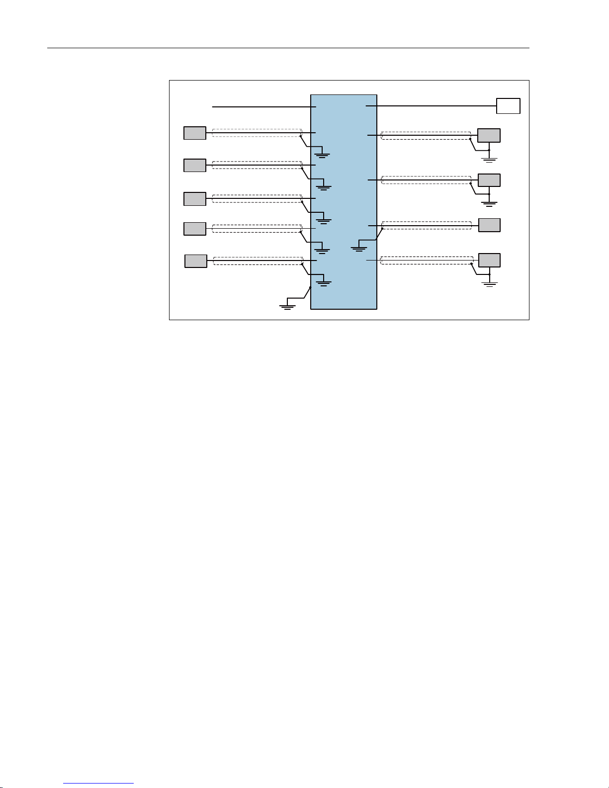
Figure 12: Grounding wires for units and shield cables
ATMD1 terminal box
B Power supply
C 2-way 2-wire transmission
D Receiver
E Temperature NMT53x
F Tank side monitor NRF560
G Temperature RCV/RCS
HContact input
I DC 4 to 20 mA input
J Installing exterior of TMD1 to a tank.
K Contact output
L DC 4 to 20 mA output
M DRM9700 communication
N BCD/Sakura code communication
A
B
D
E
F
G
H
I
J
K
L
M
N
C
4 Cable connection
Page 23
Digital transmitter TMD1 TMD1000
Endress+Hauser 23
5 Operation settings
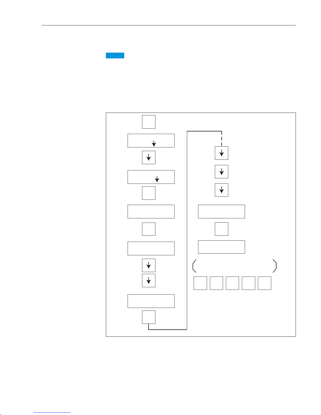
• Prepare HHT2 (Hand Held Terminal) Operation and Setting Instructions for calibration.
• After wiring check, confirm power-supply voltage (differs depending on specifications) and turn
power on. Do not turn off power, except for adjustment and maintenance.
5.1 Level adjustment operation flow
Figure 13: Flow chart
NOTICE
SELECT
䚷䚷䚷
DEVICE
E䠖I/F
䚷䚷䚷䚷 䠖
NEXT
ON
E
E
E
MODE
SELECT䚷䚷DEVICE
E䠖TMG/TM 䠖NEXT
ITEM䚷No. 04
SET LEVEL?
SET䚷LEVEL㻌㻔mm
㻕
2 0 0 0 E
Input specified level value (mm)using
numeric keys (e.g.) 2000.
PUSH
䚷䚷䚷䚷
MODE
HHT2䚷䚷 ROM VX.X
MODE䚷No. 01䚷TGM
OPERATION?
MODE䚷No. 03䚷TGM
No.1䚷SET䚷(LEVEL) ?
5 Operation settings
Page 24
Digital transmitter TMD1 TMD1000
24 Endress+Hauser
6 Operations and device settings
6.1 HHT2 (Hand Held Terminal)
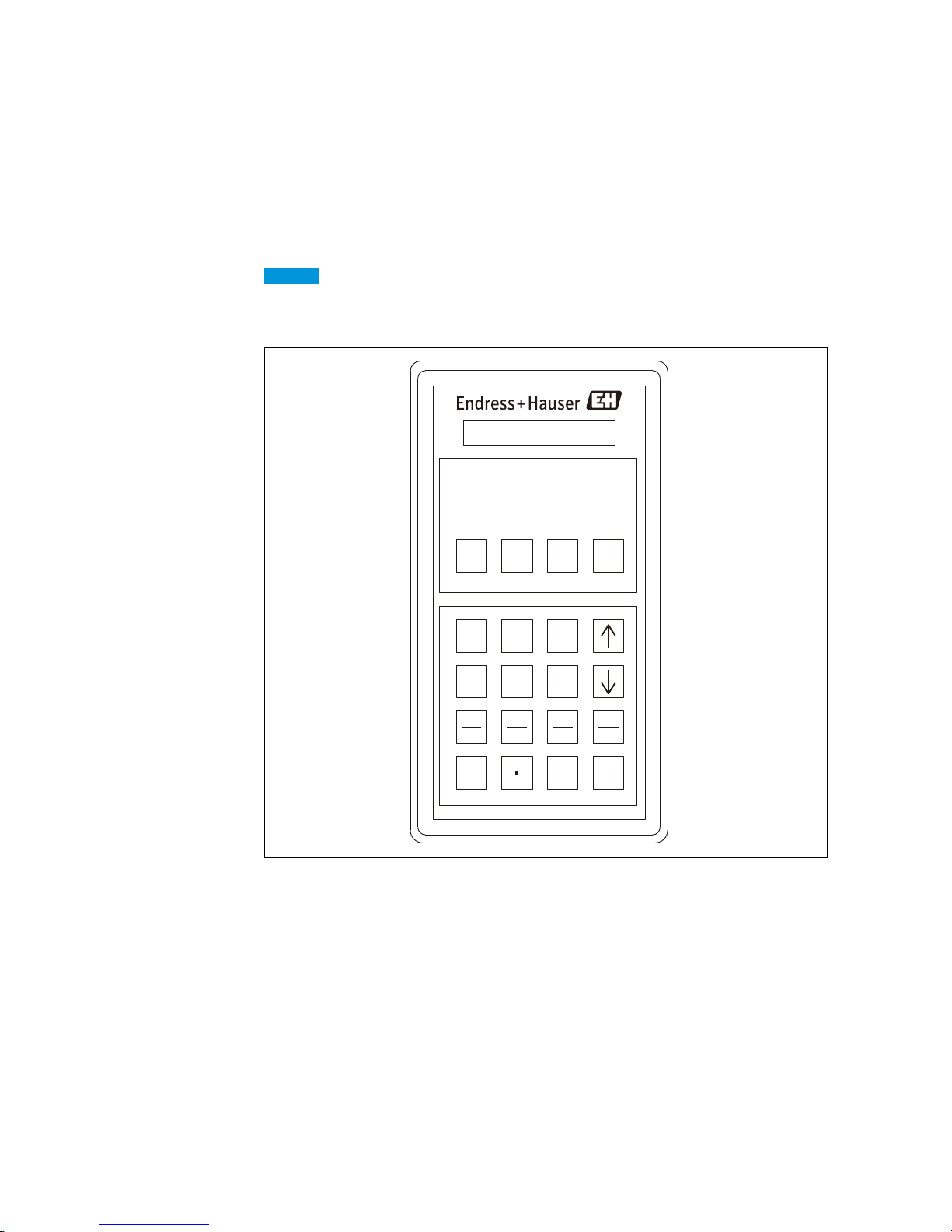
The TMD1 series operation, settings, and adjustments are easily done using the convenient Hand Held
Terminal (HHT2).
• TMD1s with HART input specification require the latest HHT2 software version (HHT V5.8 or later).
• Always take care when using explosion proof products in hazardous areas.
Figure 14: HHT2 (Hand Held Terminal)
NOTICE
SFT
MODE
OFF ON
HAND HELD TERMINAL
HHT-2-
789
0
ENT
456
123
DEF
ABC
6 Operations and device settings
Page 25
Digital transmitter TMD1 TMD1000
Endress+Hauser 25
7 Specifications, modules and mode in HHT2
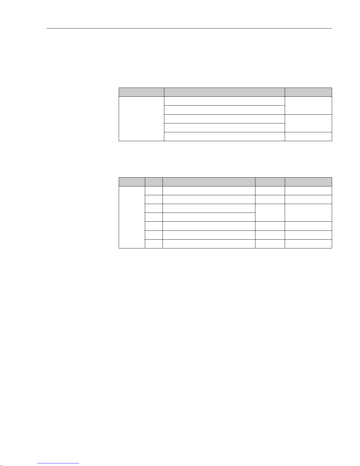
7.1 Basic specifications
7.2 Output1 specifications
Function Description Mode No.
Basic operations
Check all positions and names of installed board.
MODE00
Memory address setting/memory data display
Error status display
MODE02
Data display
Level adjustment MODE03
Function Spec. Description Module Mode No.
Output 1
1 4 to 20 mA DAC-1 MODE11
2 2-way 2-wire (MDP protocol) Exp-A MODE13
3BCD parallel
OUT-3/4 MODE05
4 Sakura code parallel
5 2-way 2-wire (MIC, BBB protocol) Exp-A MODE13
62-way 2-wire (V1 protocol) Exp-A MODE13
7 Optical FFi ODC-1 MODE15
7 Specifications, modules and mode in HHT2
Page 26

Digital transmitter TMD1 TMD1000
26 Endress+Hauser
7.3 Output 2 specifications
Function Spec. Description Module Mode No.
Output 2
A
4 to 20 mA DAC-1 MODE11, 12
4 x alarm (open collector) Exp-A MODE06
B
4 to 20 mA DAC-1 MODE11, 12
Monitor DRM DRMM-A
C
4x alarm (open collector) Exp-A MODE06
Monitor DRM DRMM-A
D
4-20 mA DAC-1 MODE11, 12
4 x alarm (open collector) Exp-A MODE06
Monitor DRM DRMM-A
E
4-20 mA DAC-1 MODE11, 12
2 x gauge operation command CNT-2 MODE01
F
2 x gauge operation command DRMM-A
Monitor DRM CNT-2 MODE01
G 4 x alarm (relay) Exp-A + CD688 MODE06
H
4-20 mA DAC-1 MODE11, 12
4 x alarm (relay) Exp-A + CD688 MODE06
J
4 x alarm (relay) Exp-A + CD688 MODE06
Monitor DRM DRMM-A
K
4-20 mA DAC-1 MODE11, 12
4 x alarm (relay) Exp-A + CD688 MODE06
Monitor DRM DRMM-A
1 4 to 20 mA DAC-1 MODE11, 12
2 4 x alarm (open collector) Exp-A MODE06
3 Monitor DRM DRMM-A
4 2 x gauge operation command CNT-2 MODE01
5
2 x gauge operation command
CNT-2 MODE01
6x outer equipment operation command
6 8 x outer equipment operation command CNT-2 MODE01
7 Specifications, modules and mode in HHT2
Page 27
Digital transmitter TMD1 TMD1000
Endress+Hauser 27
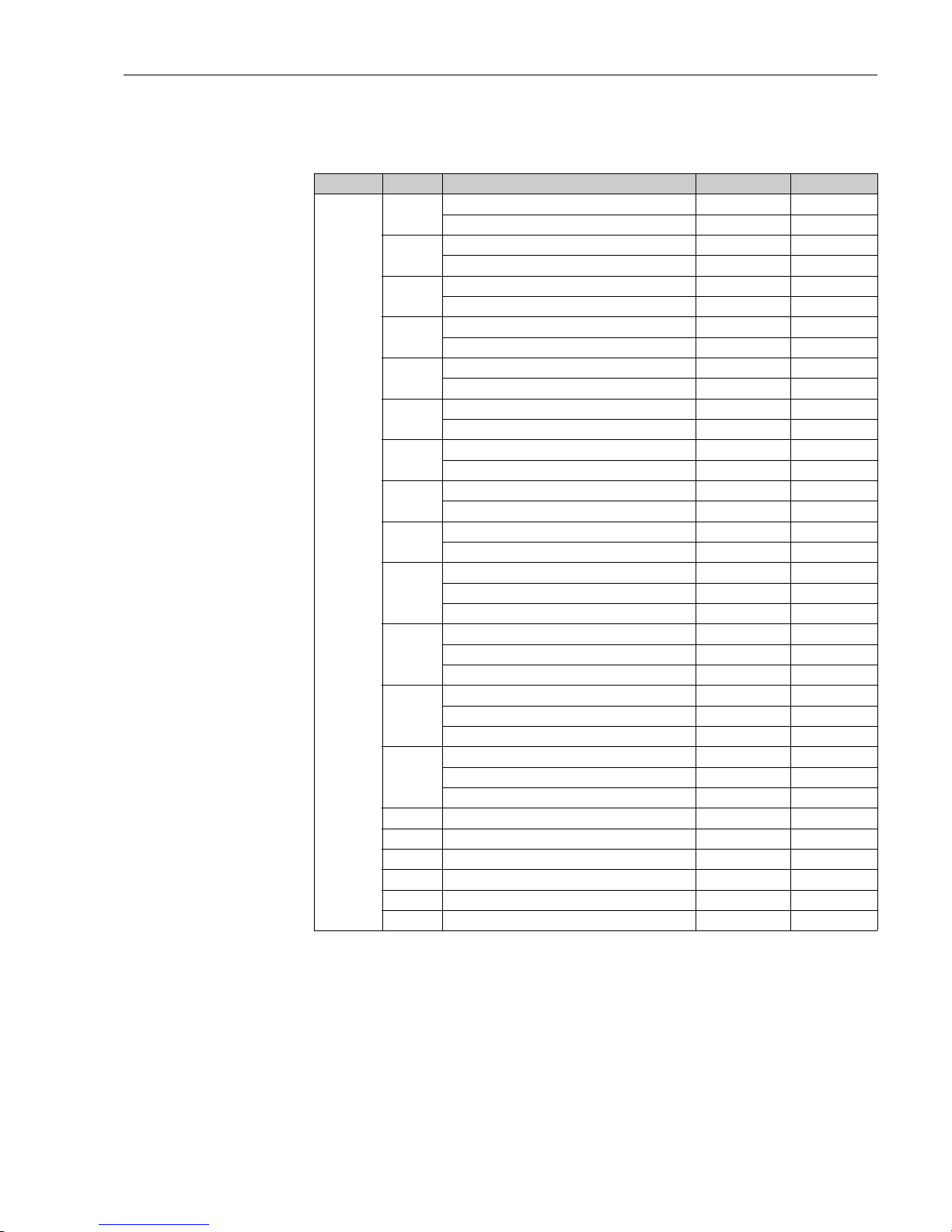
7.4 Input specifications
Function Spec. Description Module Mode No.
Input
A
4-20 mA ADC-2 MODE14
1 x spot temperature Pt100/JPt100 Thermo-A MODE07
B
4-20 mA ADC-2 MODE14
3 x point spot temperature Pt100/JPt100 Thermo-A MODE08
C
4-20 mA ADC-2 MODE14
Multi element aver mAage temperature Thermo-A MODE09
D
4-20 mA ADC-2 MODE14
Multi spot average temperature Pt100/JPt100 Thermo-A MODE10
E
4 x status INT-1/Exp-A
1 x spot temperature Pt100/JPt100 Thermo-A MODE07
F
4 x status INT-1/Exp-A
3 x spot temperature Pt100/JPt100 Thermo-A MODE08
G
4 x status INT-1/Exp-A
Multi element average temperature Thermo-A MODE09
H
4 x status INT-1/Exp-A
Multi spot average temperature Thermo-A MODE10
J
4-20 mA ADC-2 MODE14
4 x status INT-1/Exp-A
K
4-20 mA ADC-2 MODE14
4 x status Thermo-A MODE07
1 x spot temperature Pt100/JPt100 INT-1/Exp-A
L
4-20 mA ADC-2 MODE14
4 x status Thermo-A MODE08
3 x spot temperature Pt100/JPt100 INT-1/Exp-A
M
4-20 mA ADC-2 MODE14
Multi element average temperature Thermo-A MODE09
4 x status INT-1/2, Exp-A
N
4-20 mA ADC-2 MODE14
Multi spot average temperature Thermo-A MODE10
4 x status INT-1/Exp-A
1 4-20 mA ADC-2 MODE14
2 4 x status INT-1/Exp-A
3 1 x spot temperature Pt100/JPt100 Thermo-A MODE07
4 3 x spot temperature Pt100/JPt100 Thermo-A MODE08
5 Multi element average temperature Thermo-A MODE09
6 Multi spot average temperature Thermo-A MODE10
7 Specifications, modules and mode in HHT2
Page 28

Digital transmitter TMD1 TMD1000
28 Endress+Hauser
8 Maintenance
TMD requires no special maintenance.
8.1 Exterior cleaning
When cleaning the exterior of TMD, always use cleaning agents which will not cause corrosion or other
damage to the housing and its surface seals.
8.2 Seal replacement
The TMD process seal may need replacing periodically, and more frequently in extreme climates. The
period between changes will depend on cleaning frequency, temperature of target material (liquid) and
cleaning temperature.
8 Maintenance
Page 29

Digital transmitter TMD1 TMD1000
Endress+Hauser 29
9 Troubleshooting
9.1 Error message
Error message can be confirmed at the error code display MODE02 TIME13 of HTT2.
Figure 15: Error Message
The all generated error values are converted into decimals, then shown in the error code display
screen.
9.2 Error confirmation
Confirmation procedure 1
When the decimal shows 2057, value is converted into binary as follows.
The generated decimal error code shows descriptions for each error.
Confirmation procedure 2
Subtract large numbers in descending order from each error code (decimal) in 2057 (decimal), and
confirm the error description corresponding to error code in "9.3 Error message table".
00000000
DEVICE ERR. CODE
1000 0000 1001䠄Binary䠅
2057䠄Decimal
䠅
(1) NMT communication, no response
(8) NRF DEVICE Error
(2048) MIF-4, noresponse
2057䚷-
䚷
: Unable to subtract
2057䚷-
䚷
=
䚷䚷
9- =
1
9䚷䠄Error arose in error code 2048.䠅
1䚷䠄Error arose in error code 8.䠅
䠄Error arose in error code 1.䠅
0000 0000 0000 0000
0000 1000 0000 0000
0000 0000 0000 1000
0000 0000 0000 0001
8
4096
2048
Error code
9 Troubleshooting
Page 30
Digital transmitter TMD1 TMD1000
30 Endress+Hauser
9.3 Error message table
9.4 Malfunction diagnosis
Error codes Displays Items Error descriptions Causes
1 0000 0000 0000 0001 HART communication NMT communication No response
2 0000 0000 0000 0010 NMT device Error code
4 0000 0000 0000 0100 NRF COMM
8 0000 0000 0000 1000 NRF Devise
256 0000 0001 0000 0000 EEROM EEROM Inaccessible
8192 0010 0000 0000 0000 SRAM
512 0000 0010 0000 0000 System External 12V Disconnection
1024 0000 0100 0000 0000 Internal 12V Disconnection
2048 0000 1000 0000 0000 MIF-4 No response
4096 0001 0000 0000 0000 Temperature system Element trouble Open, short
Conditions Causes
Off-line of communication between
HHT2 and TMD
TMD main power is off.
(power switch is off, internal fuse breakage or disconnection of internal power cable)
Abnormal level data
Level encoder circuit malfunction
(level encoder or level A/D I/F malfunction)
No change in level data
Looseness between level gauge and coupling
Looseness of gear set screw on gear unit
Misaligning of shaft gear and internal panel gear
Abnormal output 1 data Data is not set appropriately.
Abnormal output 2 data Data is not set appropriately.
Abnormal input data Data is not set appropriately.
9 Troubleshooting
Page 31
Digital transmitter TMD1 TMD1000
Endress+Hauser 31
9.5 Return
The measuring device must be returned if repairs or a factory calibration are required, or if the wrong
measuring device has been ordered or delivered. According to legal regulations, Endress+Hauser, as an
ISO-certified company, is required to follow certain procedures when handling returned products that
are in contact with medium. To ensure swift, safe and professional device returns, please read the
return procedures and conditions on the Endress+Hauser website at www.services.endress.com/
return-material
9.6 Disposal
Observe the following notes during disposal:
• Observe valid federal/national regulations.
• Ensure proper separation and reuse of the device components.
9.7 Software history
Main CPU-B
Software version/date Software changes Documentation changes
V1.10/2008.09 Original versions BA1007N
V1.11/2009.05 Valve control -
V1.12/2010.08 V1 NMT data BA01007G
V1.13/2017.09
Update the Tankvision level value to
correspond to the float level
BA00427G
9 Troubleshooting
Page 32
Digital transmitter TMD1 TMD1000
32 Endress+Hauser
10 Option
10.1 Modules
TMD1 is available in variety option modules. By installing modules as necessary, various customer
specification requests may be built and filled economically.
10.2 Module types
Name Functions Size
Number of
terminals for
standard use
Remakes
Main CPU - B CPU module A 6 Be sure to install this module.
Exp - A
2-way 2-wire digital pulse
Contact output (alarm) 4 points
Contact input (status) 4 points
A
2
8
8
Transistor output
Thermo - A
Average temperature
Spot temperature
A
12
3
For average and sport temperatures
DAC - 1 4 to 20 mA analog output C 2 2 modules are available to install.
OUT- 3/4 BCD parallel output B 18
OUT-3: Collector common
OUT-4: Emitter common
ADC - 2
DC 4 to 20 mA
Analog signal input
C2
Available for use with 2-wire
transmission board only
INT - 2 Status input C 16
Available for use with 2-wire
transmission board only (max. 8
points)
INT - 1 Status input C 8
Available for use with 2-wire
transmission board only (max. 4
points)
DRMM- A DRM communication C 2
ODC-1
Optical communication
(2-way half-duplex transmission)
Optical digital pulse
C0
CNT-2
External operation device output
B16Max. 8 points
CD-688 Alarm contact output C 8
Standard 4 points
Mechanical relay output
10 Option
Page 33

Digital transmitter TMD1 TMD1000
Endress+Hauser 33
11 Technical data
Items Descriptions
Level A/D conversion
Method: Optical non-contact absolute encoder
Range: 0 to 99999 mm
Accuracy: ±1 mm
Power supply
AC 60, 100, 110, 200, 220V ± 10 50/60 Hz
DC 20 to 32V
When ordering special specifications, contact Endress+Hauser representatives.
Power consumption
AC: max. 14 W
DC: max. 10 W
Allowable ambient
temperature
-20 to +60 ºC (-4 to 140 ºF) (Ex type)
-10 to +40 ºC (-14 to 104 ºF) (Non Ex type)
Approval Weather proof: IP65 Flame proof: Ex d IIB T4
Cable Entry
0:
A: PF(G)1-1/2, B: PF(G)3/4, C: PF(G)1, D: PF(G)1
(Screw position is fixed (refer to External dimension.))
H:
2 x thread G1 EXPC-28B, 2 x blind plug
(The position of screw hole can be specified by either of A, B,C, D.)
J:
3 x thread G1 EXPC-28B, 1 x blind plug
(The position of screw hole can be specified by either of A, B,C, D.)
K:
4 x thread G1 EXPC-28B
(The position of screw hole can be specified by either of A, B,C, D.)
L:
2 x thread G3/4 EXPC-22B,2 x blind plug
(The position of screw hole can be specified by either of A, B,C, D.)
M:
3 x thread G3/4 EXPC-22B,1 x blind plug
(The position of screw hole can be specified by either of A, B,C, D.)
N:
4 x thread G3/4 EXPC-22B
(The position of screw hole can be specified by either of A, B,C, D.)
P: 4 x thread NPT 1
Q: 4 x thread NPT 3/4
Arrester Standard equipment
Weight Approximately 10kg
Material
Electrical housing: AC4C-T6
Cover of electrical housing: AC4C-T6
Terminal box: ADC12
Cover of electrical housing: AC4C-T6
Color Blue and white
11 Technical data
Page 34

www.addresses.endress.com
 Loading...