

Page 1
TI00112R/09/EN/14.18
71404946
2018-05-31
Products
Solutions Services
Technical Information
TH53, TH54 and TH55
Thermocouple assemblies in thermowells with
spring loaded insert and enclosure for process
industry
Application
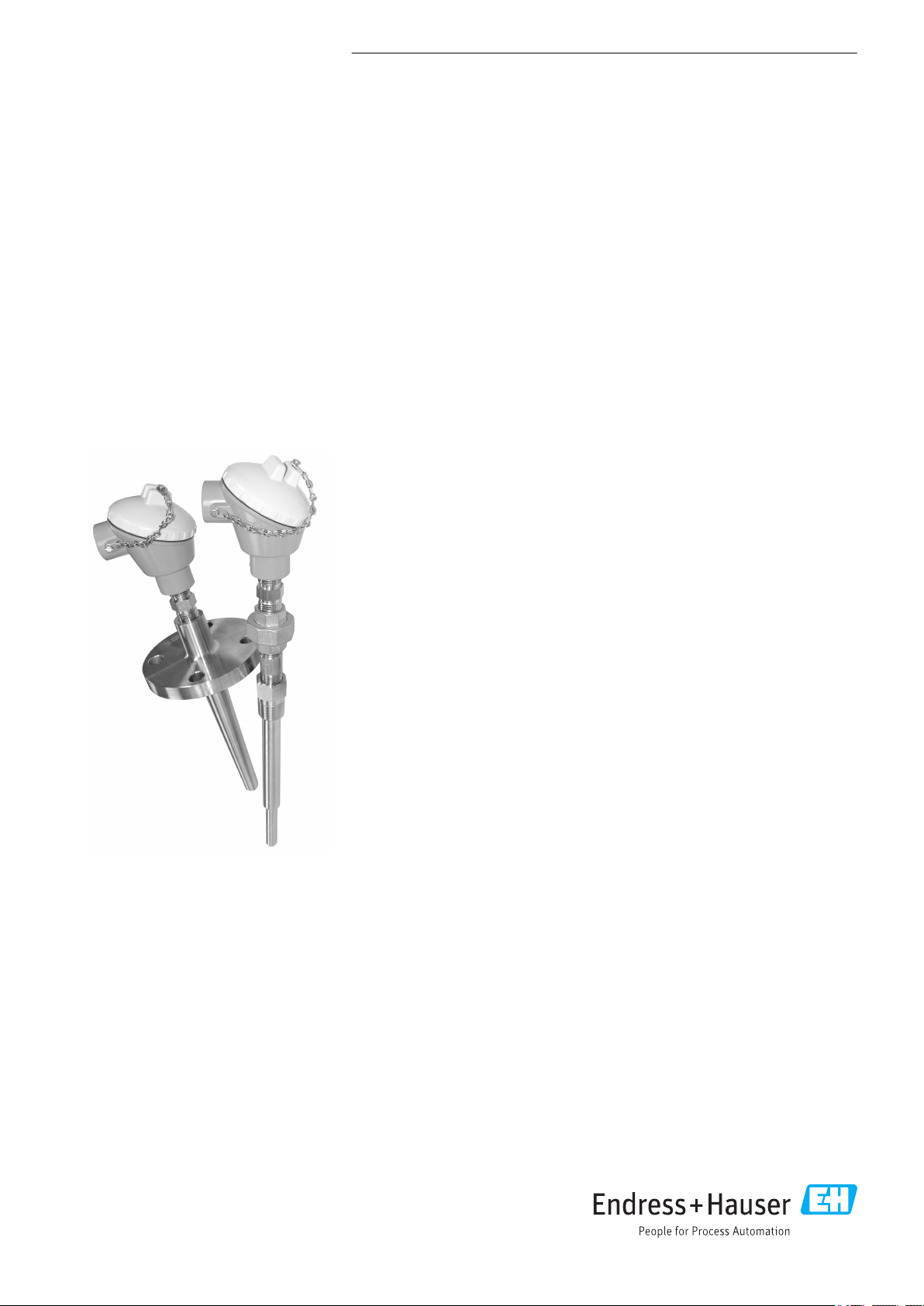
The TH53, TH54 and TH55 temperature sensors are thermocouple assemblies
installed in thermowells and designed for use in all types of process industries,
including heavy industries, due to their rugged design. They are made up of a
magnesium oxide insulated thermocouple as a measurement probe and a thermowell
made of barstock material.
The sensor assemblies can be used in process industries such as:
• Chemicals
• Petrochemicals
• Power plants
• Refineries
• Offshore platforms
Head transmitter
All Endress+Hauser transmitters are available with enhanced accuracy and reliability
compared to directly wired sensors. Instead of directly wiring your temperature
sensors to your control system, use transmitters to reduce wiring and maintenance
costs while increasing measurement accuracy.
Field transmitter
Temperature field transmitters with HART® or FOUNDATION Fieldbus™ protocol for
highest reliability in harsh industrial environments. Backlit display with large
measured value, bargraph and fault condition indication for ease of reading.
Your benefits
• One source shopping for temperature measurement solutions. World class
transmitter with integrated sensor offering for heavy process industry applications.
• Remove and install straight out of the box!
• Improved galvanic isolation on most devices (2 kV).
• Simplified model structure: Competitively priced, offers great value. Easy to order
and reorder. A single model number includes sensor, thermowell and transmitter
assembly for a complete point solution.
• All iTEMP transmitters provide long-term stability ≤ 0.05% per year.
Page 2
Function and system design
K
E
E
P
T
I
G
H
T
W
H
E
N
C
I
R
C
U
I
T
A
L
I
V
E
I
N
E
X
P
L
O
S
I
V
E
A
T
M
O
S
P
H
E
R
E
°C
°F
%
K
10
0
20
30
40
50
60
70
80
90
100
!
K
E
E
P
T
I
G
H
T
W
H
E
N
C
I
R
C
U
I
T
A
L
I
V
E
I
N
E
X
P
L
O
S
I
V
E
A
T
M
O
S
P
H
E
R
E
°C
°F
%
K
10
0
20
30
40
50
60
70
80
90
100
!
Endress+Hauser
RMS 621
On
∆p (Q)
T2
T1
Deltabar S
TMT162
TMT162
TH54
flanged thermowell
TH53
tilted,
threaded
thermowell
RMS621
Heat
exchange
process
Measuring principle Thermocouples (TC)
Thermocouples are comparatively simple, robust temperature sensors which use the Seebeck effect
for temperature measurement: if two electrical conductors made of different materials are connected
at a point, a weak electrical voltage can be measured between the two open conductor ends if the
conductors are subjected to a thermal gradient. This voltage is called thermoelectric voltage or
electromotive force (emf.). Its magnitude depends on the type of conducting materials and the
temperature difference between the "measuring point" (the junction of the two conductors) and the
"cold junction" (the open conductor ends). Accordingly, thermocouples primarily only measure
differences in temperature. The absolute temperature at the measuring point can be determined
from these if the associated temperature at the cold junction is known or is measured separately and
compensated for. The material combinations and associated thermoelectric voltage/temperature
characteristics of the most common types of thermocouple are standardized in the IEC 60584 and
ASTM E230/ANSI MC96.1 standards.
Measuring system
TH53, TH54 and TH55
A0027371-EN
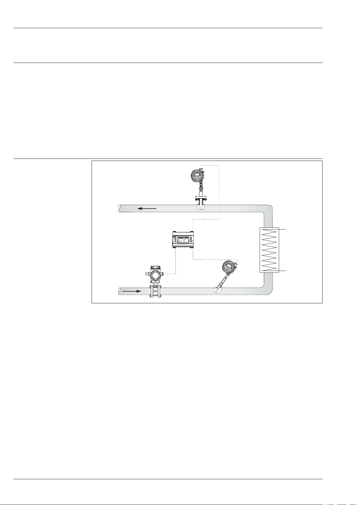
1 Application example
Calculation of heat quantity which is emitted or absorbed by a water flow in a heating or cooling
system. The quantity of heat is calculated from the process variable for Δp flow (Q) and the
differential from the feed and return temperature (T2 - T1). Bidirectional energy calculations, such
as the calculating systems with changing flow direction (charging/ discharging the heat
accumulator) are also possible.
Energy manager RMS621
Energy conservation and cost expenditures are significant issues in today's industry. Accurate flow monitoring
2 Endress+Hauser
and calculation is the basis for thorough analysis and billing of energy. This data can serve as a basis to
maximize savings potential and help in controlling operational costs on a daily basis. Endress+Hauser's energy
managers provide accurate and reliable calculations for the monitoring and control of energy consumption
(both produced and consumed) according to international standards, e.g. IAPWS-IF 97, AGA8, ISO 5167 etc.
For RMS621 details, see "Documentation".
iTEMP TMT162 Temperature Field Transmitter
Aluminum or stainless steel dual compartment explosion - proof enclosure and compact, fully potted electronics
provide the ultimate protection in harshest environments. TMT162 prevents costly plant shutdowns by
detecting corrosion on RTDs or thermocouples before it corrupts the measured value. Endress+Hauser's Field
Temperature Transmitters with backlit display and sensor backup functionality are designed with safety in
mind to keep your plant, equipment and personnel safe. More information on this can be found in the Technical
Information, see "Documentation".
Page 3
TH53, TH54 and TH55
Deltabar S/Cerabar S
The evolution series of Cerabar S/Deltabar S represents a decisive step ahead in making pressure
instrumentation better and safer for the process industry. The development of new products thrives especially
on the knowledge, commitment and experience of staff members. Permanent high performance can only be
achieved if dedicated and enthusiastic people provide their ideas. Endress+Hauser's instruments are not only
supposed to distinguish themselves for customers and users by technological novelties but also by the presence
of people supporting this progress, be it in service, sales or production. More information on this can be found
in the Technical Information, see "Documentation".
Input
Measured variable
Measurement range
Temperature (temperature-linear transmission behavior)
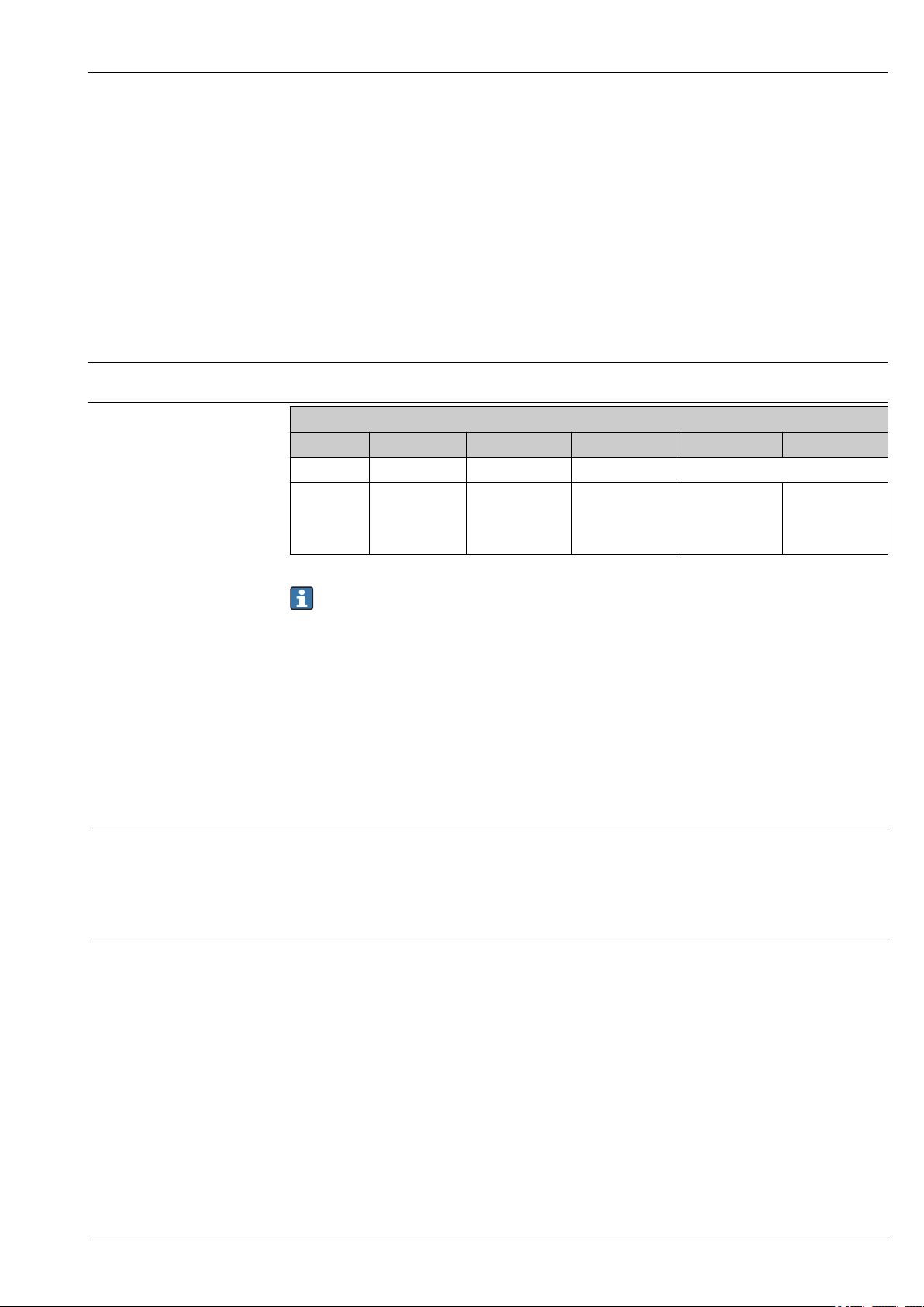
Upper Temperature limits for various thermocouple types in °C (°F)
Sheath OD Type T Type J Type E Type K Type N
⌀¼" 370 °C (700 °F) 720 °C (1 330 °F) 820 °C (1 510 °F) 1 150 °C (2 100 °F)
Maximum
element
temperature
range limits
–270 to +400 °C
(–
454 to +752 °F)
–210 to +1 200 °C
(–
346 to +2 192 °F)
–270 to +1 000 °C
(–
454 to +1 832 °F)
–270 to +1 372 °C
(–
454 to +2 500 °F)
–270 to +1 300 °C
454 to +2 372 °F)
These values are valid for single and duplex thermocouples. The temperature limits given are
intended only as a guide to the user and should not be taken as absolute values or as
guarantees of satisfactory life or performance. These types and sizes are sometimes used at
temperatures above the given limits, but usually at the expense of stability or life or both. In
other instances, it may be necessary to reduce the above limits in order to achieve adequate
service.
Thermocouples with 316 SS sheath and assemblies with 316 SS thermowells are rated for a
maximum temperature of 927 °C (1 700 °F).
Output
(–
Output signal
Generally, the measured value can be transmitted in one of two ways:
• Directly-wired sensors - sensor measured values forwarded without a transmitter.
• Via all common protocols by selecting an appropriate Endress+Hauser iTEMP temperature
transmitter. All the transmitters listed below are mounted directly in the terminal head or as field
transmitter and wired with the sensory mechanism.
Family of temperature transmitters
Thermometers fitted with iTEMP transmitters are an installation-ready complete solution to
improve temperature measurement by significantly increasing accuracy and reliability, when
compared to direct wired sensors, as well as reducing both wiring and maintenance costs.
PC programmable head transmitters
They offer a high degree of flexibility, thereby supporting universal application with low inventory
storage. The iTEMP transmitters can be configured quickly and easily at a PC. Endress+Hauser offers
free configuration software which can be downloaded from the Endress+Hauser Website. More
information can be found in the Technical Information.
HART® programmable head transmitters
The transmitter is a 2-wire device with one or two measuring inputs and one analog output. The
device not only transfers converted signals from resistance thermometers and thermocouples, it also
transfers resistance and voltage signals using HART® communication. It can be installed as an
intrinsically safe apparatus in Zone 1 hazardous areas and is used for instrumentation in the
terminal head (flat face) as per DIN EN 50446. Swift and easy operation, visualization and
Endress+Hauser 3
Page 4
TH53, TH54 and TH55
maintenance using universal device configuration tools like FieldCare, DeviceCare or
FieldCommunicator 375/475. For more information, see the Technical Information.
PROFIBUS® PA head transmitters
Universally programmable head transmitter with PROFIBUS® PA communication. Conversion of
various input signals into digital output signals. High accuracy over the complete ambient
temperature range. The configuration of PROFIBUS PA functions and of device-specific parameters is
performed via fieldbus communication. For more information, see the Technical Information.
FOUNDATION Fieldbus™ head transmitters
Universally programmable head transmitter with FOUNDATION Fieldbus™ communication.
Conversion of various input signals into digital output signals. High accuracy over the complete
ambient temperature range. All transmitters are released for use in all important process control
systems. The integration tests are performed in Endress+Hauser's "System World". For more
information, see the Technical Information.
Advantages of the iTEMP transmitters:
• Dual or single sensor input (optionally for certain transmitters)
• Pluggable display (optionally for certain transmitters)
• Unsurpassed reliability, accuracy and long-term stability in critical processes
• Mathematical functions
• Monitoring of the thermometer drift, sensor backup functionality, sensor diagnostic functions
• Sensor-transmitter matching for dual sensor input transmitters, based on Callendar/Van Dusen
coefficients
Field transmitter
Field transmitter with HART® or FOUNDATION Fieldbus™ communication and backlit display. Can
be read easily from a distance, in sunlight and at night. Large measurement value, bargraph and
fault indication displayed. Benefits are: dual sensor input, highest reliability in harsh industrial
environments, mathematic functions, thermometer drift monitoring and sensor back-up
functionality, corrosion detection.
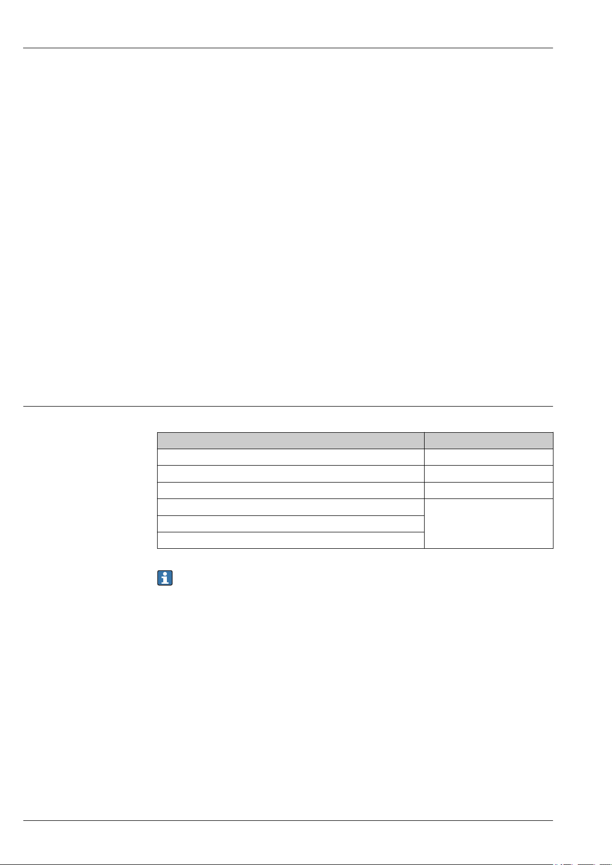
Galvanic isolation
Galvanic isolation of Endress+Hauser iTEMP transmitters
Transmitter type Sensor
TMT181 PCP Û = 3.75 kV AC
TMT182 HART® U = 2 kV AC
TMT162 HART® Field transmitter U = 2 kV AC
TMT82 HART®
U = 2 kV ACTMT84 PA
TMT85 FF
In applications where fast response time is needed, grounded thermocouples are recommended.
This thermocouple design may cause a ground loop. This can be avoided by using iTEMP
transmitters with high galvanic isolation.
4 Endress+Hauser
Page 5
TH53, TH54 and TH55
1
2
11.5...35 V
11.5...30 V Ex
4
6
TC
mA
4...20 mA
-
+
+
1
-
2
7
6
5
4
3
1
2
7
6
5
4
3
Sensor
input 2
Sensor
input 1
Bus connection
and supply voltage
Display connection
TC
TC
+
-
1
2
3
4
5
6
+
-
3
4
S1
3
S2
-
+
+
-
#
Sensor 1
Sensor 2 (not TMT142)
Power supply
field transmitter and
analog output 4 to 20 mA,
or bus connection
1
6
2
5
TC
TC
Sensor 1
Sensor 2 (not TMT142)
Power supply
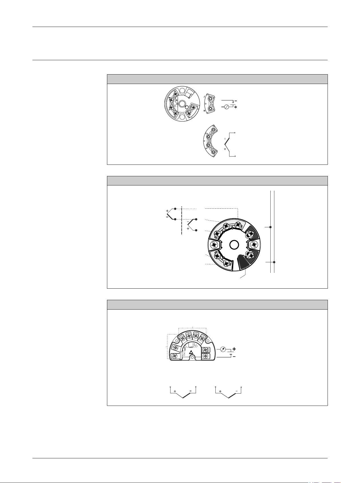
Terminal assignment
Type of sensor connection
Head transmitter mounted TMT18x (single input)
A0026046
Head mounted transmitter TMT8x (dual input)
Endress+Hauser 5
A0012699-EN
Field mounted transmitter
A0026944-EN
Page 6
TH53, TH54 and TH55
1
2
-
-
+
+
Sensor 2
Sensor 1
4
+
-
1
2
3
5
6
+
-
3
4
S1
3
S2
-
+
+
-
!
+
Sensor 2
Sensor 1
-
Bus connection and
supply voltage
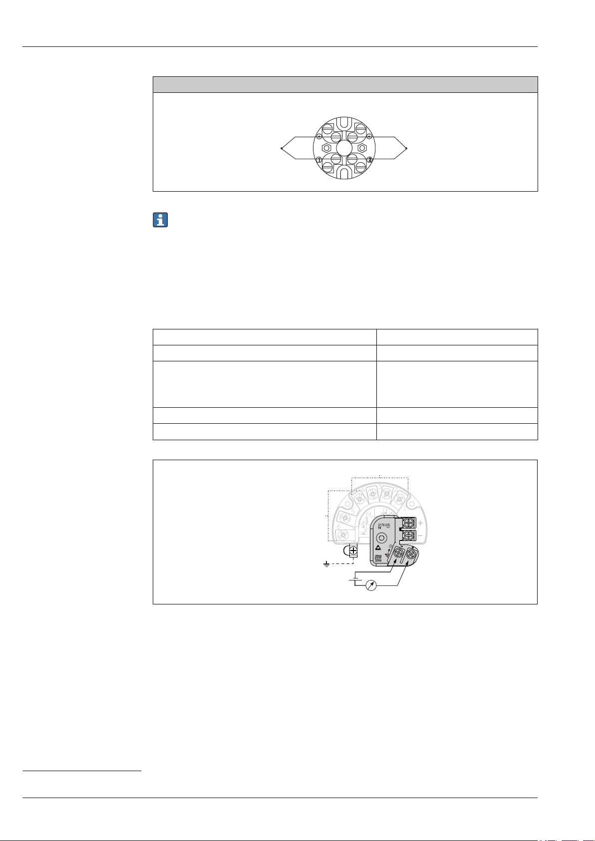
Terminal block mounted
A0026045-EN
The blocks and transmitters are shown as they sit inside the heads in reference to the conduit
opening.
Integrated overvoltage protection
The integrated overvoltage protection module can be ordered as an optional extra
protects the electronics from damage from overvoltage. Overvoltage occurring in signal cables (e.g.
4 to 20 mA, communication lines (fieldbus systems) and power supply is diverted to ground. The
functionality of the transmitter is not affected as no problematic voltage drop occurs.
Connection data:
1)
. The module
Maximum continuous voltage (rated voltage) UC = 42 V
Nominal current I = 0.5 A at T
Surge current resistance
• Lightning surge current D1 (10/350 µs)
• Nominal discharge current C1/C2 (8/20 µs)
• I
• In = 5 kA (per wire)
DC
amb.
= 1 kA (per wire)
imp
= 80 °C (176 °F)
In = 10 kA (total)
Temperature range –40 to +80 °C (–40 to +176 °F)
Series resistance per wire 1.8 Ω, tolerance ±5 %
2 Electrical connection of the overvoltage protection
A0033027-EN
Grounding
The device must be connected to the potential equalization. The connection between the housing and the local
ground must have a minimum cross-section of 4 mm2 (13 AWG) . All ground connections must be secured
tightly.
1) Available for the field transmitter with HART® 7 specification
6 Endress+Hauser
Page 7
TH53, TH54 and TH55
1
2
Wire specifications
Thermocouple color codes according to ASTM E-230
Thermocouple grade, TFE insulated 20AWG, 7 strands with stripped ends
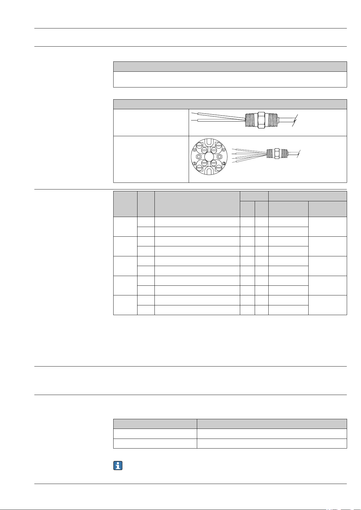
Electrical connection
Flying leads, standard 139.7 mm (5.5 in) for wiring in connection head, head mounted transmitter or terminal
block mounted, and for wiring with TMT162 or TMT142 assemblies
Design of leads
Flying leads 139.7 mm (5.5 in)
with stripped ends
A0027297
Connection with terminal block (4
pole) with stripped ends
A0027298
T.C. Type POS
E EP (+) Nickel - 10% chromium X Purple Brown
J JP (+) Iron X White Brown
K KP (+) Nickel - 10% chromium X Yellow Brown
T TP (+) Copper X Blue Brown
N NP (+) Nickel - 14% chromium - 1.5% silicon X Orange Brown
Material MAGNETIC Insulation
NEG
EN (-) Copper - 45% nickel (constantan) X Red
JN (-) Copper - 45% nickel (constantan) X Red
KN (-) Nickel - 5% (aluminum, silicon)
TN (-) Copper - 45% nickel (constantan) X Red
NN (-) Nickel - 4.5% silicon - 0.1% magnesium X Red
1)
YES NO Single conductor Overall T.C.
X Red
wire
1) Silicon, or aluminum and silicon may be present in combination with other elements.
Performance characteristics
Reference conditions
Response time
Endress+Hauser 7
These data are relevant for determining the accuracy of the temperature transmitters used. More
information on this can be found in the Technical Information of the iTEMP temperature
transmitters.
63% response time per ASTM E839
Thermocouple assembly TH55 without thermowell
Junction style Thermocouple insert ⌀¹⁄₄"
Grounded 1.3 s
Ungrounded 2.9 s
Response time for the sensor assembly without transmitter.
Page 8
TH53, TH54 and TH55
Response time examples for thermocouples assemblies with thermowell TH53 and TH54
Construction Stepped thermowell Tapered thermowell ³⁄₄" straight thermowell
Time 15 s 20 s 25 s
Response times for thermocouple assemblies with thermowell are provided for general design
guidance without transmitter.
When the temperature of a process media changes, the output signal of a Thermocouple assembly
follows this change after a certain time delay. The physical cause is the time related to heat transfer
from the process media through the thermowell and the insert to the sensor element
(thermocouple). The manner in which the reading follows the change in temperature of the
assembly over time is referred to as the response time. Variables that influence or impact the
response time are:
• Wall thickness of thermowell
• Spacing between thermocouple insert and thermowell
• Sensor packing
• Process parameters such as media, flow velocity, etc.
Maximum measured error
Transmitter long-term stability
Insulation resistance
Thermocouples corresponding to ASTM E839
Type Temperature range Standard tolerance (IEC class 2) Special tolerance (IEC class 1)
[°C] whichever is greater [°C] whichever is greater
E 0 to 870 °C (32 to 1 600 °F)
J 0 to 760 °C (32 to 1 400 °F) ±2.2 or ±0.75% ±1.1 or ±0.4%
K 0 to 1 260 °C (32 to 2 300 °F) ±2.2 or ±0.75% ±1.1 or ±0.4%
T 0 to 370 °C (32 to 700 °F) ±1 or 0.75% ±0.5 or ±0.4%
N 0 to 1 260 °C (32 to 2 300 °F) ±2.2 or ±0.75% ±1.1 or ±0.4%
±1.7 or ±0.5% ±1 or ±0.4%
For measurement errors in °F, calculate using equation above in °C, then mulitply the outcome
by 1.8.
≤ 0.1 °C (0.18 °F) / year or ≤ 0.05 % / year
Data under reference conditions; % relates to the set span. The larger value applies.
Insulation resistance for MgO insulated thermocouples with ungrounded hot junction between
terminals and probe sheath, test voltage 500 VDC.
1000 MΩ at 25 °C (77 °F)
These values for insulation resistance also apply between each thermocouple wire at single and
duplex constructions with ungrounded hot junction.
Calibration specifications
The manufacturer provides an option to provide comparison temperature calibrations from
–20 to 300 °C (–4 to 572 °F)
2)
on the International Temperature Scale of 1990. Calibrations are
traceable to standards maintained by the National Institute of Standards and Technology (NIST).
Calibration services are in conformance with ASTM E220, IEC 17025 and ANSI/NCSL Z540-1-1994.
The report of calibration is referenced to the serial number of the assembly.
Three point calibrations are provided, given that the specified temperatures are within the
recommended range and the minimum length requirements are met as specified. The minimum
length is based on the overall length "x" of the spring loaded insert.
2) Other ranges may be available on request.
8 Endress+Hauser
Page 9
TH53, TH54 and TH55
U
U
B
A
U
C
Installation conditions
Orientation
Installation instructions
No restrictions.
A0025312
3 Installation examples
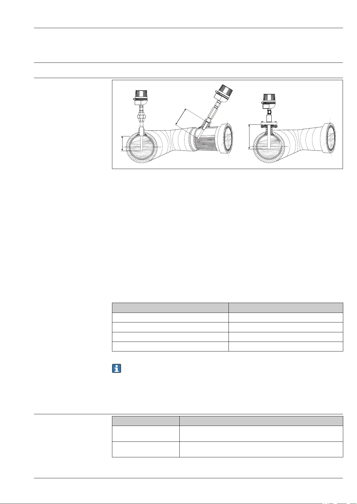
A-C In pipes with a small cross section the thermowell tip should reach or extend slightly past the center line of
the pipe (= U)
B Threaded, angled installation of TH53 assembly
C Flange installation of TH54 assembly
The immersion length of the thermometer influences the accuracy. If the immersion length is too
small then errors in the measurement are caused by heat conduction via the process connection and
the container wall. If installing into a pipe then the immersion length should be at least half of the
pipe diameter. A further solution could be an angled (tilted) installation (see B). When determining
the immersion length all thermometer parameters and the process to be measured must be taken
into account (e.g. flow velocity, process pressure).
• Installation possibilities: Pipes, tanks or other plant components
• Minimum immersion length per ASTM E644, ΔT ≤ 0.05 °C (0.09 °F):
For temperature assemblies with thermowell (TH53 and TH54) the minimum immersion is the
depth to which the thermowell is immersed in the medium, measured from the tip. To minimize
errors from ambient temperature the following minimum immersion lengths are recommended:
Construction Minimum immersion
Stepped thermowell 63.5 mm (2.5 in)
Tapered thermowell 114.3 mm (4.5 in)
¾" straight thermowell 101.6 mm (4 in)
Weld-in thermowell 114.3 mm (4.5 in)
TH55 assemblies can only be used in existing thermowells.
Environment
Ambient temperature range
Endress+Hauser 9
Terminal head Temperature in °C (°F)
Without mounted head
transmitter
With mounted head
transmitter
Depends on the terminal head used and the cable gland or fieldbus connector,
see 'Terminal heads' section
–40 to 85 °C (–40 to 185 °F)
SIL mode (HART 7 transmitter): –40 to 70 °C (–40 to 158 °F)
Page 10

Terminal head Temperature in °C (°F)
With mounted head
transmitter and display
With mounted field
transmitter
–20 to 70 °C (–4 to 158 °F)
• Without display: –40 to 85 °C (–40 to 185 °F)
• With display and/or integrated overvoltage protection module:
–40 to +80 °C (–40 to +176 °F)
• SIL mode: –40 to +75 °C (–40 to +167 °F)
TH53, TH54 and TH55
Shock and vibration resistance
4 g/2 to 150 Hz as per IEC 60068-2-6
10 Endress+Hauser
Page 11
TH53, TH54 and TH55
A
¾”
¼”
¼”
¼”
"¼”
½”
½”
½”
½”
NPT
½”
NPT
½”
"¼”
"5/8”"5/8”
"½”
T
1¾” + T
1¾” + T
U
Q
Q
Q
U
U
2½”
1”
A
A
P P
X
E
E
X
A
X
X
A
2 1/4” + T
U
Q
4
5
6
7
8
1
2
3
"0.26”
"0.26”
"0.26”
X
A
"0.26”
"5/8”
¼”
¼”
"¾”
Full penetration
weld thermowell
Standard weld
thermowell
Mechanical construction
Design, dimensions
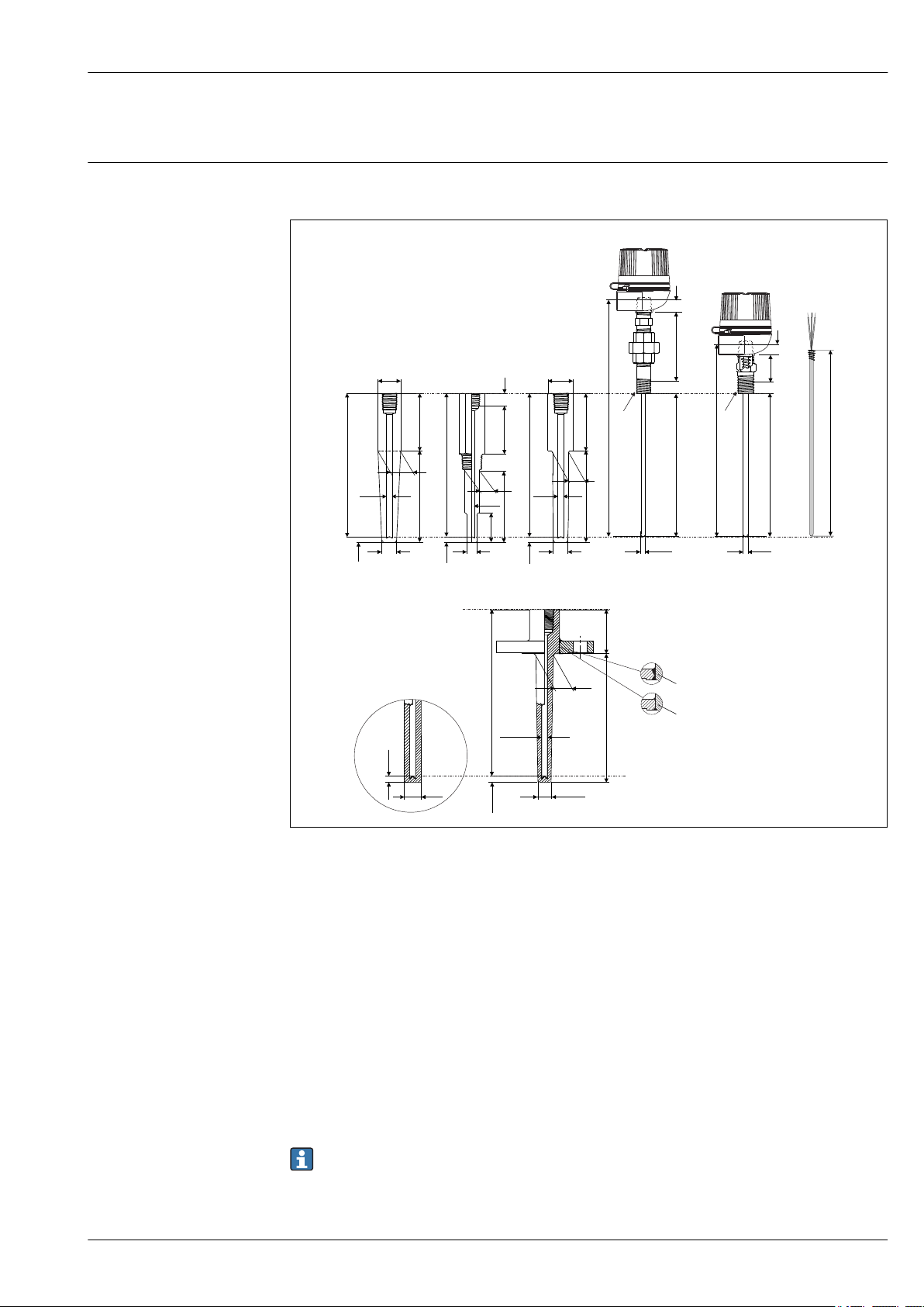
All dimensions in inch. For values related to the graphics please refer to the tables and equations
below.
4 Dimensions of the sensor assemblies
1 TH53 weld-in thermowell (tapered)
2 TH53 threaded thermowell (stepped)
3 TH53 socket weld thermowell (tapered)
4 TH53/TH54 extension, nipple-union-nipple (NUN), without thermowell
5 TH55 extension hex nipple without thermowell
6 TU121 spring loaded insert
7 TH54 flange thermowell (tapered)
8 Straight thermowell tip
E Extension length
P Pipe size
Q Thermowell root diameter
T Lag dimension
U Thermowell immersion length
XA Immersion length thermocouple sensor
A Drill depth of thermowell
X Overall insert length
A0027685-EN
For TH53 thermowells with ½" NPT and 1" process thread length and ¾" hex length dimensions,
spring loaded sensor assemblies must be used with the thermowells.
Endress+Hauser 11
Page 12
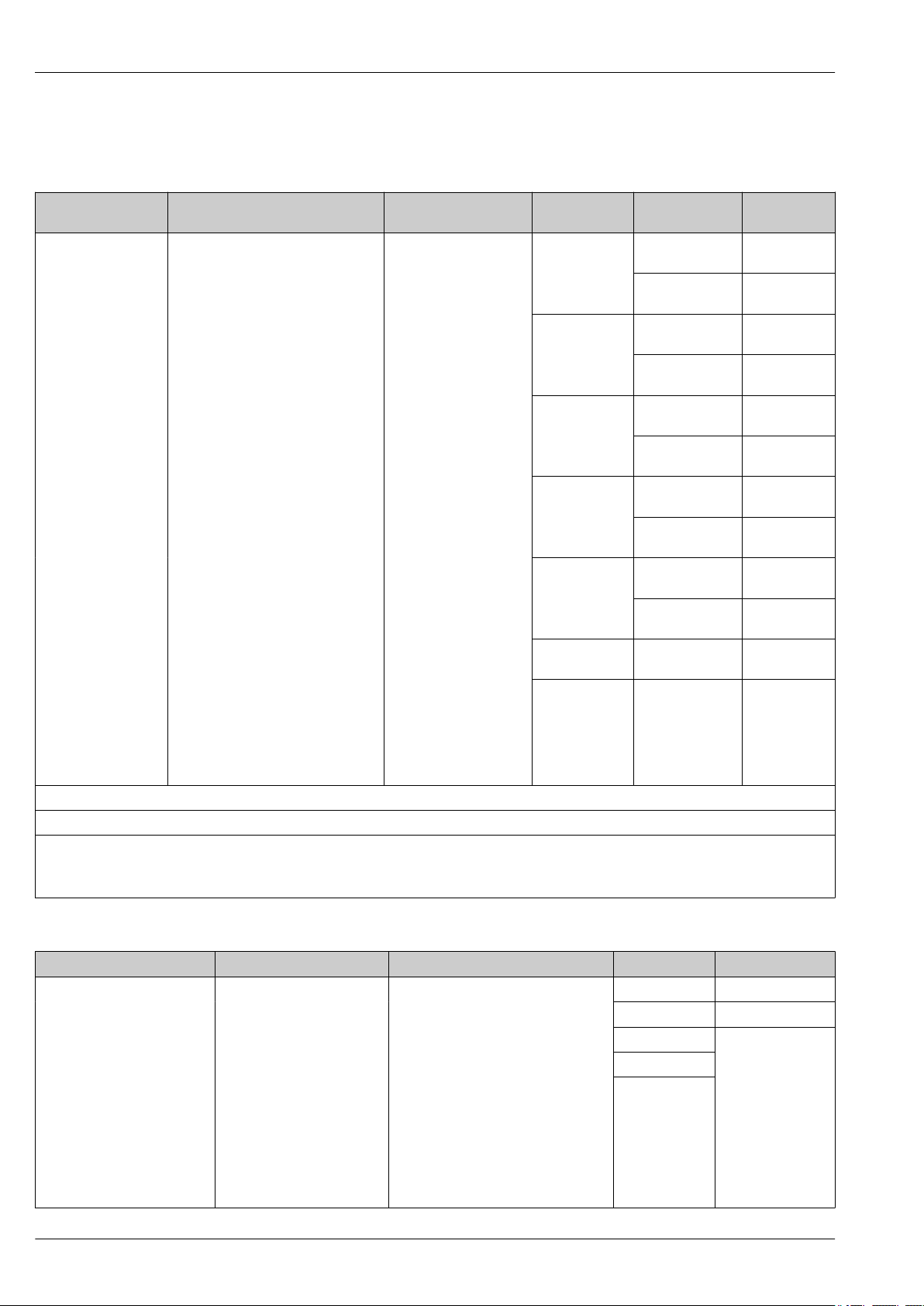
Dimensions of TH53
TH53, TH54 and TH55
All thermowells are marked with a material ID, CRN (Canadian Registration Number) and heat
number.
U E (nominal dimension) T Process
connection
63.5 mm (2.5 in) Material: Steel or 316
Hex nipple = 25.4 mm (1 in)
Nipple Union Nipple (NUN) =
114.3 mm (4.5 in)
190.5 mm (7.5 in)
266.7 mm (10.5 in)
342.9 mm (13.5 in)
419.1 mm (16.5 in)
571.5 mm (22.5 in)
specified length
50.8 to 609.6 mm
(2 to 24 in) in ½"
increments
Immersion length thermocouple sensor = thermowell drilled length X A= A = U + 38.1 mm (1.5 in) + T
Overall insert length X = A + E
P = Pipe size
• ¾" Nominal utilizes 1.050"
• 1" Nominal utilizes 1.315"
101.6 mm (4 in)
177.8 mm (7 in)
76.2 mm (3 in) or
specified length
25.4 to 152.4 mm
(1 to 6 in) in ½"
increments
½" NPT Stepped (standard
¾" NPT Stepped (standard
1" NPT Stepped (standard
¾" socket weld Stepped (standard
1" socket weld Stepped (standard
¾" weld in Tapered (heavy
1" weld in Tapered (heavy
Shape of
thermowell
duty)
Tapered (heavy
duty)
duty)
Tapered (heavy
duty)
duty)
Tapered (heavy
duty)
duty)
Tapered (heavy
duty)
duty)
Tapered (heavy
duty)
duty)
duty)
⌀Q
16 mm (⁵⁄₈ in)
16 mm (⁵⁄₈ in)
19.05 mm
(³⁄₄ in)
22.3 mm
(⁷⁄₈ in)
22.3 mm
(⁷⁄₈ in)
26.9 mm (1¹⁄₁₆
in)
19.05 mm
(³⁄₄ in)
22.3 mm
(⁷⁄₈ in)
22.3 mm
(⁷⁄₈ in)
25.4 mm (1 in)
26.6 mm
(1.050 in)
33.4 mm
(1.315 in)
Dimensions of TH54
U E (nominal dimension) T Flange size ⌀Q, tapered version
50.8 mm (2 in) Hex nipple = 25.4 mm (1 in) or specified length 25.4 mm (1 in) 22.3 mm (⁷⁄₈ in)
101.6 mm (4 in) Nipple Union Nipple (NUN) =
177.8 mm (7 in)
254 mm (10 in)
330.2 mm (13 in)
406.4 mm (16 in)
558.8 mm (22 in)
specified length
50.8 to 609.6 mm (2 to 24 in)
in ½" increments
101.6 mm (4 in)
177.8 mm (7 in)
25.4 to 254 mm (1 to 10 in) in ½"
increments
38.1 mm (1¹⁄₂ in) 26.9 mm (1¹⁄₁₆ in)
50.8 mm (2 in) 26.9 mm (1¹⁄₁₆ in)
76.2 mm (3 in)
12 Endress+Hauser
Page 13
TH53, TH54 and TH55
U E (nominal dimension) T Flange size ⌀Q, tapered version
Immersion length thermocouple sensor = thermowell drilled
length
Overall insert length X = A + E
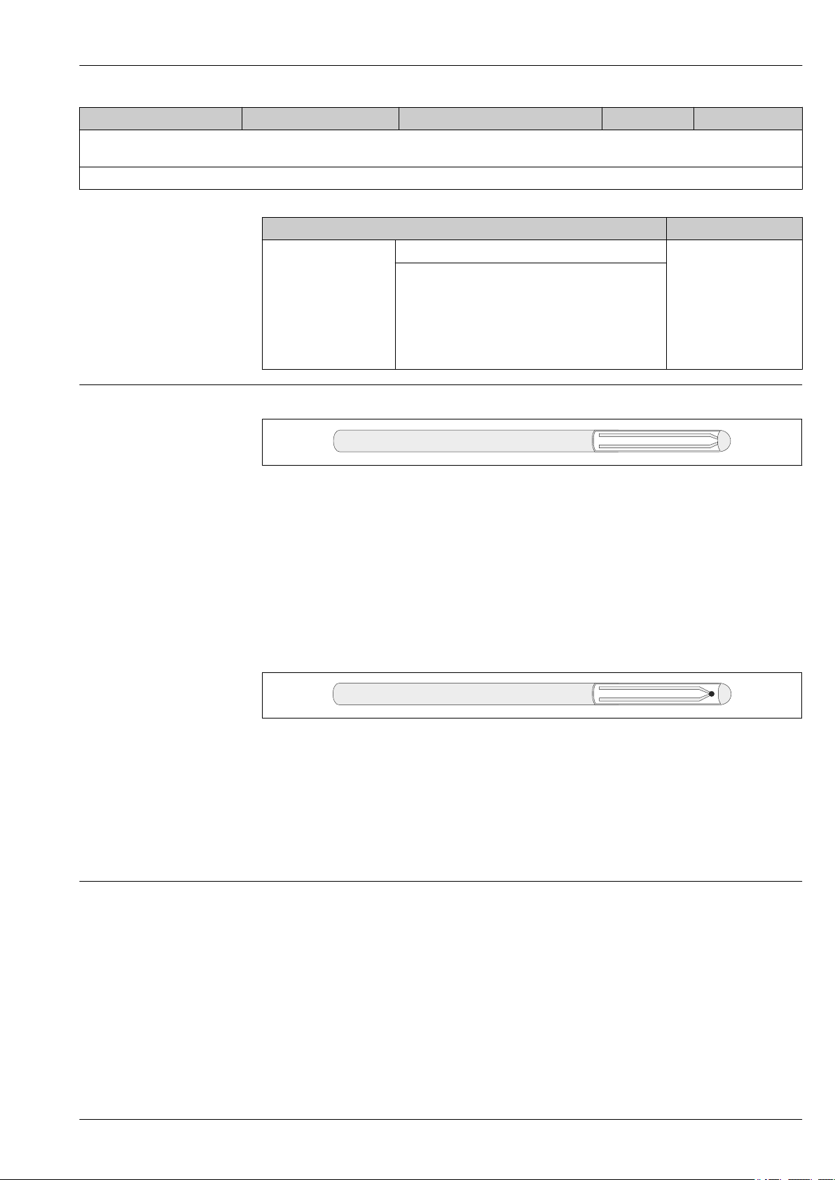
Dimensions of TH55 (without thermowell) Extension E
Immersion length Thermocouple sensor X
Hot or measuring junction Grounded junction
X = A = U + 50.8 mm (2 in) + T
A
101.6 mm (4 in)
152.4 mm (6 in)
228.6 mm (9 in)
304.8 mm (12 in)
355.6 mm (14 in)
specified length 101.6 to 762 mm (4 to 30 in) in ½"
increments
Hex nipple =
25.4 mm (1 in)
or
Nipple Union Nipple
(NUN) = 101.6 mm (4 in)
177.8 mm (7 in)
A0026086
5 Grounded junction
The thermocouple junction is welded securely into the closure end of the sheath, becoming an
integral part of the weld. This is a good general purpose, low cost junction providing faster response
times than an ungrounded junction of similar sheath diameter. Grounded junctions should not be
used with Type T thermocouples, due to the copper wire. For a reliable temperature reading of
grounded thermocouples transmitters with galvanic isolation are strongly recommended. iTEMP
transmitters have galvanic isolation of min. 2 kV (from the sensor input to the output and the
housing).
Ungrounded junction
A0026087
6 Ungrounded junction
The welded thermocouple junction is fully isolated from the welded closed end sheath. This junction
provides electrical isolation to reduce problems associated with electrical interference. Ungrounded
junctions are also recommended for use in extreme positive or negative temperatures, rapid thermal
cycling and for ultimate corrosion resistance of the sheath alloy. iTEMP transmitters have an
excellent noise immunity (EMC) meeting all requirements listed under IEC 61326 for use in noisy
environments.
Weight
1 to 30 lbs
Endress+Hauser 13
Page 14
TH53, TH54 and TH55
Material
Process connection and thermowell
The temperatures for continuous operation specified in the following table are only intended as
reference values for use of the various materials in air and without any significant compressive load.
The maximum operation temperatures are reduced considerably in some cases where abnormal
conditions such as high mechanical load occur or in aggressive media.
Material
name
AISI 316/
1.4401
AISI 316L/
1.4404
1.4435
Alloy600 NiCr15Fe 1 100 °C (2 012 °F) • A nickel/chromium alloy with very good resistance to
Short form Recommended
max. temperature
for continuous
use in air
X5CrNiMo17-12-2 650 °C (1 202 °F)
X2CrNiMo17-12-2
650 °C (1 202 °F)
X2CrNiMo18-14-3
Properties
1)
• Austenitic, stainless steel
• High corrosion resistance in general
• Particularly high corrosion resistance in chlorinebased and acidic, non-oxidizing atmospheres through
the addition of molybdenum (e.g. phosphoric and
sulfuric acids, acetic and tartaric acids with a low
concentration)
1)
• Austenitic, stainless steel
• High corrosion resistance in general
• Particularly high corrosion resistance in chlorinebased and acidic, non-oxidizing atmospheres through
the addition of molybdenum (e.g. phosphoric and
sulfuric acids, acetic and tartaric acids with a low
concentration)
• Increased resistance to intergranular corrosion and
pitting
• Compared to 1.4404, 1.4435 has even higher
corrosion resistance and a lower delta ferrite content
aggressive, oxidizing and reducing atmospheres, even
at high temperatures
• Resistant to corrosion caused by chlorine gas and
chlorinated media as well as many oxidizing mineral
and organic acids, sea water etc.
• Corrosion from ultrapure water
• Not to be used in a sulfur-containing atmosphere
Process connection
1) Can be used to a limited extent up to 800 °C (1472 °F) for low compressive loads and in non-corrosive
media. Please contact your Endress+Hauser sales team for further information.
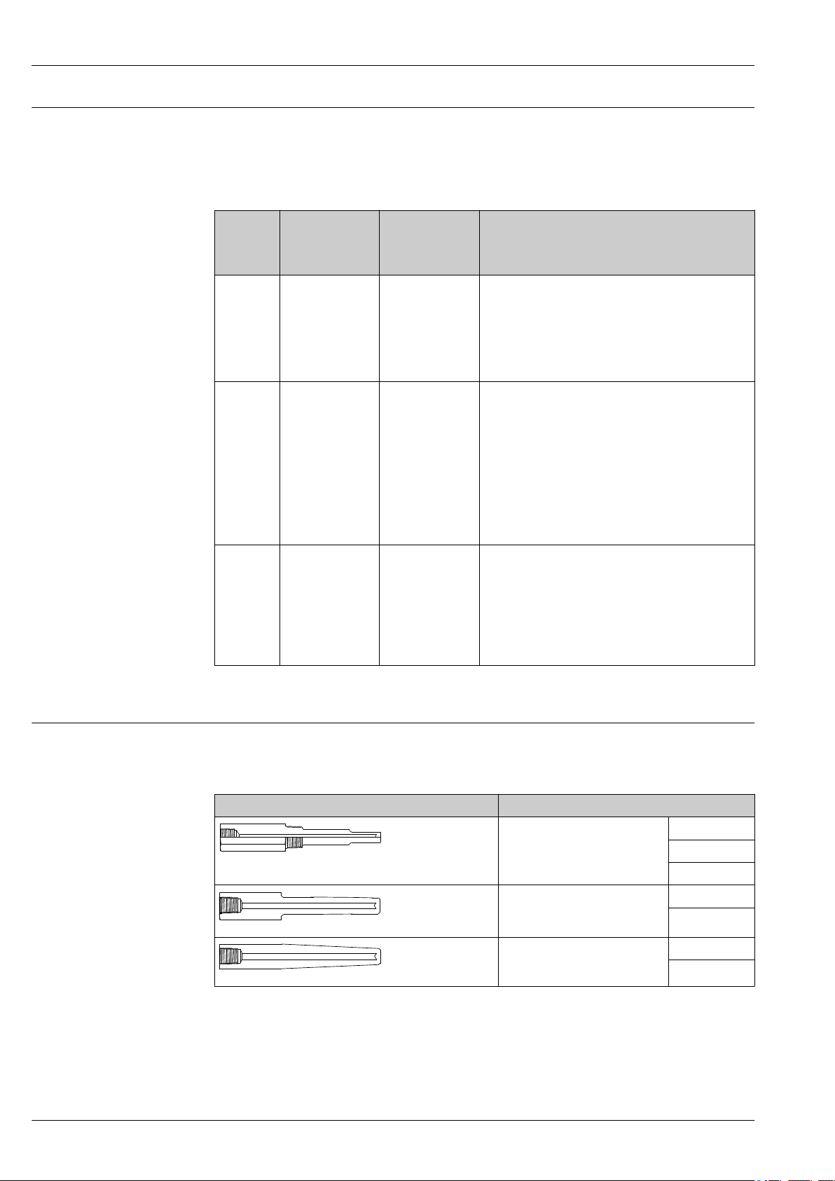
The process connection is the means of connecting the thermometer to the process. The following
process connections are available:
TH53
Thread Version
NPT thread NPT 1/2"
A0026110
NPS for socket weld NPS 3/4"
A0026111
NPS for weld-in NPS 3/4"
A0026108
NPT 3/4"
NPT 1"
NPS 1"
NPS 1"
14 Endress+Hauser
Page 15
TH53, TH54 and TH55
L
D
K
d
b
f
N
N
ML
TL
ML
Type
N
Type
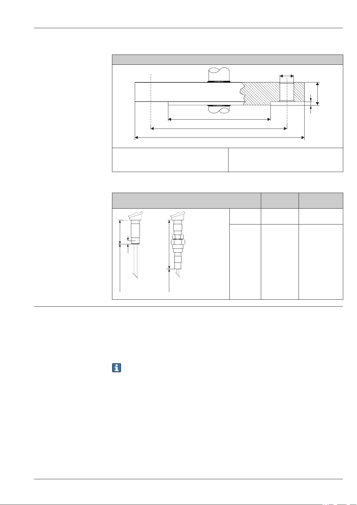
NUN
TH54
Flange
For detailed information on the flange dimensions
refer to the following flange standard:
ANSI/ASME B16.5
TH55
A0010471
The flange material must be the same as of the stem
of the thermowell.
Type Thermowell
Housing Terminal heads
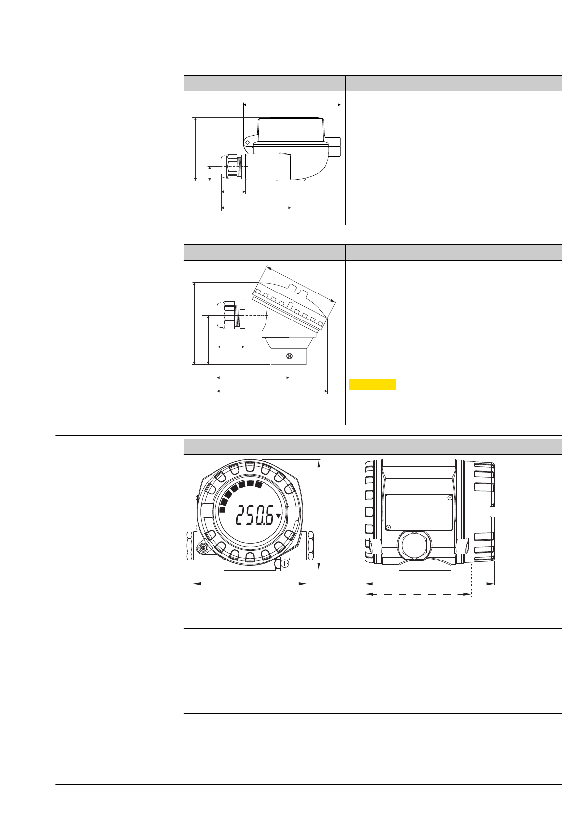
All terminal heads have an internal shape and size in accordance with DIN EN 50446, flat face and a
thermometer connection with a ½" NPT thread. All dimensions in mm (in). Specifications without
head transmitter installed. For ambient temperatures with head transmitter installed, see the
'Environment' section.
As a special feature, Endress+Hauser offers terminal heads with optimized terminal accessibility for
easy installation and maintenance.
Some of the specifications listed below may not be available on this product line.
Type N ½" NPT external
Type NUN ½" NPT external
A0026181
connection
thread
thread
Extension neck
lengths in mm (in)
25.4 mm (1 in)
101.6 mm (4 in)
177.8 mm (7 in)
Endress+Hauser 15
Page 16
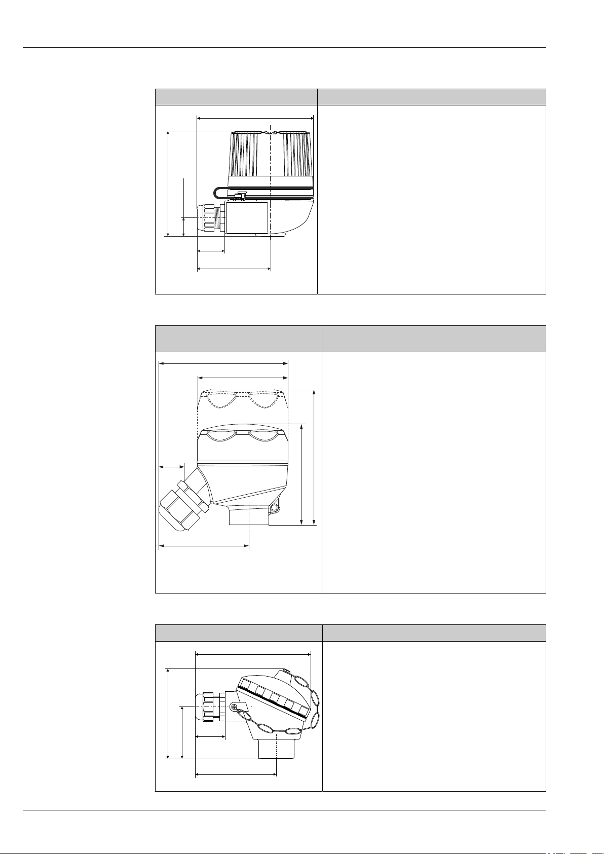
TA30H with display window in cover Specification
125 (4.92)
115 (4.53)
28
(1.1)
78 (3.01)
20.5 (0.8)
64 (2.52)
96 (3.8)
64 (2.52)
71 (2.8)
25 (1)
96 (3.8)*
84 (3.3)
95 (3.9)
57 (2.2)
122 (4.8)
28 (1.1)
• Flameproof (XP) version, explosion-protected, captive screw
cap, available with one or two cable entries
• Degree of protection: IP 66/68, NEMA Type 4x Encl.
Ex-version: IP 66/67
• Temperature: –50 to +150 °C (–58 to +302 °F) for rubber seal
without cable gland (observe max. permitted temperature of
cable gland!)
• Material:
– Aluminum with polyester powder coating
– Stainless steel 316L without coating
• Thread: ½" NPT, ¾" NPT, M20x1.5, G½"
• Extension neck/thermowell connection: ½" NPT
• Color of aluminum head: blue, RAL 5012
• Color of aluminum cap: gray, RAL 7035
• Weight:
– Aluminum: approx. 860 g (30.33 oz)
A0009831
– Stainless steel: approx. 2 900 g (102.3 oz)
• Head transmitter optionally available with TID10 display
TH53, TH54 and TH55
TA30R (optionally with display window in
cover)
A0017145
* Dimensions of version with display window
in cover
Specification
• Degree of protection - standard version: IP69K (NEMA Type
4x encl.)
Degree of protection - version with display window: IP66/68
(NEMA Type 4x encl.)
• Temperature: –50 to +130 °C (–58 to +266 °F) without cable
gland
• Material: stainless steel 316L, abrasive-blasted or polished
Seals: EPDM
Display window: polycarbonate (PC)
• Cable entry thread ½" NPT and M20x1.5
• Weight
– Standard version: 360 g (12.7 oz)
– Version with display window: 460 g (16.23 oz)
• Display window in cover optionally for head transmitter with
display TID10
• Protection armature connection: M24x1.5 or ½" NPT
• Ground terminal: internal in standard version; external
terminal optionally available
• Available in conjunction with 3-A marked sensors
TU401 Specification
• Protection class: IP65 (NEMA Type 4x encl.)
16 Endress+Hauser
• Temperature: –40 to 130 °C (–40 to 266 °F) silicone, up to
100 °C (212 °F) rubber seal without cable gland (observe
max. permitted temperature of the cable gland!)
• Material: aluminum alloy with polyester or epoxy coating,
rubber or silicone seal under the cover
• Cable entry: M20x1.5 or plug M12x1 PA
• Protection armature connection: M24x1.5, G 1/2" or NPT
1/2"
• Head color: blue, RAL 5012
• Cap color: gray, RAL 7035
• Weight: 300 g (10.58 oz)
A0008669
Page 17
TH53, TH54 and TH55
107.5 (4.23)
68.5 (2.7)
28
(1.1)
78 (3.1)
15.5 (0.6)
122 (4.8)
28
(1.1)
78 (3.1)
50 (1.97)
87 (3.43)
81.7 (3.22)
K
E
E
P
T
I
G
H
T
W
H
E
N
C
I
R
C
U
I
T
A
L
I
V
E
I
N
E
X
P
L
O
S
I
V
E
A
T
M
O
S
P
H
E
R
E
°C
10
0
20
30
40
50
60
70
80
90
100
110 (4.33)
112 (4.41)
132.5 (5.22)*
TU401 (TA30A style) Specification
• Available with one or two cable entries
• Protection class: IP66/68 (NEMA Type 4x encl.)
• Temperature: –50 to +150 °C (–58 to +302 °F) without cable
gland
• Material: aluminum, polyester powder coated
Seals: silicone
• Threaded cable entry: ½" NPT, ¾" NPT or plug 7/8" FF
• Protection armature connection: M24x1.5
• Head color: blue, RAL 5012
• Cap color: gray, RAL 7035
• Weight: 330 g (11.64 oz)
• Ground terminal, internal and external
A0009820
• With 3-A symbol
TU401 (TA30S style) Specification
• Degree of protection: IP65 (NEMA Type 4x encl.)
• Temperature: –40 to +85 °C (–40 to +185 °F) without cable
gland
• Material: polypropylene (PP), FDA-compliant, seals: O-ring
EPDM
• Cable entry thread: ¾" NPT (with adapter for ½" NPT),
M20x1.5
• Protective assembly connection: ½" NPT
• Color: white
• Weight: approx. 100 g (3.5 oz)
• Ground terminal: only internal via auxiliary terminal
CAUTION
L
Potential electrostatic charging hazard
A0017146
Not recommended for use in hazardous (classified)
‣
locations.
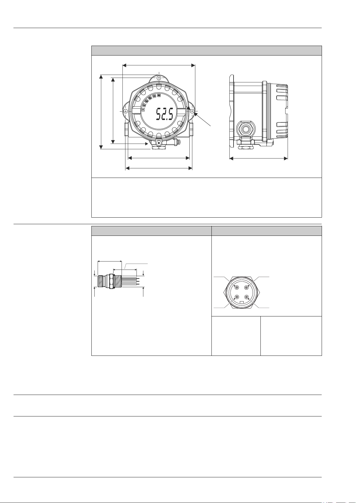
Field transmitters
Temperature field transmitter iTEMP TMT162
* Dimensions without display = 112 mm (4.41 in)
• Separate electronics compartment and connection compartment
• Protection class: IP67, NEMA type 4x
• Material: Die-cast aluminum housing AlSi10Mg with powder coating on polyester base, 316L
• Display rotatable in 90° increments
• Cable entry: 2x ½" NPT
• Brilliant backlit display with ease of visibility in bright sunshine or pitch darkness
• Gold plated terminals to avoid corrosion and additional measurement errors
• SIL certification as per IEC 61508:2010 (HART-protocol)
Endress+Hauser 17
A0024608
Page 18
TH53, TH54 and TH55
132 (5.2)
135 (5.3)
112 (4.4)
106 (4.2)
121 (4.8)
121 (4.8)
!6.4
(0.25)
0
10
30
40
50
20
°F
190 (7.48)
26.5
(1.040)
NPT 1/2”
A
1 3
2 4
Temperature field transmitter iTEMP HART® TMT142
• Protection class: IP67, NEMA type 4x
• Material: Die-cast aluminum housing AlSi10Mg with powder coating on polyester base
• Display rotatable in 90° increments
• Cable entry: 3x ½" NPT
• Brilliant blue backlit display with ease of visibility in bright sunshine or pitch darkness
• Gold plated terminals to avoid corrosion and additional measurement errors
A0025824
Fieldbus connector
CE Mark
Type, dimensions in mm (in) Specification
Fieldbus connector to PROFIBUS PA or FOUNDATION
Fieldbus™
Pos. A: M12 on PROFIBUS PA connector 7/8-16 UNC on
FOUNDATION Fieldbus™ connector
• Ambient temperature:
–40 to 150 °C (–40 to 300 °F)
• Degree of protection: IP67
Wiring diagram:
A0027381
PROFIBUS PA
Pos 1: gray (shield)
Pos 2: brown (+)
Pos 3: blue (-)
Pos 4: not connected
A0006023
FOUNDATION Fieldbus™
Pos 1: blue (-)
Pos 2: brown (+)
Pos 3: not connected
Pos 4: ground (green/
yellow)
Certificates and approvals
The device meets the legal requirements of the EC directives if applicable. Endress+Hauser confirms
that the device has been successfully tested by applying the CE mark.
Other standards and guidelines
18 Endress+Hauser
• IEC 60529: Degree of protection of housing (IP code)
• IEC 61010-1: Safety requirements for electrical equipment for measurement, control, and
laboratory use – Part 1: General requirements
• IEC 60584 and ASTM E230/ANSI MC96.1: Thermocouples
• ASTM E-230: Standard Specification and Temperature-Electromotive Force (EMF) Tables for
Standardized Thermocouples
Page 19

TH53, TH54 and TH55
• ASTM E839: American society for testing and materials, standard test methods for sheathed
thermocouples and sheathed thermocouple material
• NEMA - ANSI/NEMA 250: Enclosures for Electrical Equipment
• ASME PTC 19.3 TW2010: Performance test codes
UL
CSA GP
Temperature transmitters UL recognized components under Category Code.file number
QUYX8.E225237 and QUYX2.E225237
The installed and assembled temperature transmitters (iTEMP series) are CSA GP approved.
Ordering information
Detailed ordering information is available from the following sources:
• In the Product Configurator on the Endress+Hauser website: www.endress.com -> Click "Corporate"
-> Select your country -> Click "Products" -> Select the product using the filters and search field ->
Open product page -> The "Configure" button to the right of the product image opens the Product
Configurator.
• From your Endress+Hauser Sales Center: www.addresses.endress.com
Product Configurator - the tool for individual product configuration
• Up-to-the-minute configuration data
• Depending on the device: Direct input of measuring point-specific information such as
measuring range or operating language
• Automatic verification of exclusion criteria
• Automatic creation of the order code and its breakdown in PDF or Excel output format
• Ability to order directly in the Endress+Hauser Online Shop
Endress+Hauser 19
Page 20
TH53, TH54 and TH55
Accessories
Various accessories, which can be ordered with the device or subsequently from Endress+Hauser, are
available for the device. Detailed information on the order code in question is available from your
local Endress+Hauser sales center or on the product page of the Endress+Hauser website:
www.endress.com.
Device-specific accessories
Communication-specific accessories
Adapter M20x1.5 - ½" NPT cable entry
Order code: 51004387
Cable gland ½" NPT, D4.5-8.5, IP 68
Order code: 51006845
Integrated overvoltage
protection module
Configuration kit TXU10 Configuration kit for PC-programmable transmitter with setup software and
Commubox FXA195
HART
Commubox FXA291 Connects Endress+Hauser field devices with a CDI interface (= Endress+Hauser
Wireless HART adapter
SWA70
The module protects the electronics from overvoltage. Available for TMT162
housing (not T17 hygienic version).
interface cable for PC with USB port
Order code: TXU10-xx
For intrinsically safe HART communication with FieldCare via the USB interface.
For details, see "Technical Information" TI00404F
Common Data Interface) and the USB port of a computer or laptop.
For details, see "Technical Information" TI00405C
Is used for the wireless connection of field devices.
The WirelessHART adapter can be easily integrated into field devices and existing
infrastructures, offers data protection and transmission safety and can be operated
in parallel with other wireless networks with minimum cabling complexity.
For details, see Operating Instructions BA061S
Service-specific accessories
Field Xpert SFX350 Field Xpert SFX350 is a mobile computer for commissioning and maintenance. It
enables efficient device configuration and diagnostics for HART and FOUNDATION
Fieldbus devices in the non-Ex area.
For details, see Operating Instructions BA01202S
Field Xpert SFX370 Field Xpert SFX370 is a mobile computer for commissioning and maintenance. It
enables efficient device configuration and diagnostics for HART and FOUNDATION
Fieldbus devices in the non-Ex area and the Ex area.
For details, see Operating Instructions BA01202S
Accessories Description
Applicator Software for selecting and sizing Endress+Hauser measuring devices:
• Calculation of all the necessary data for identifying the optimum measuring
device: e.g. pressure loss, accuracy or process connections.
• Graphic illustration of the calculation results
Administration, documentation and access to all project-related data and
parameters over the entire life cycle of a project.
Applicator is available:
• Via the Internet: https://portal.endress.com/webapp/applicator
• On CD-ROM for local PC installation.
20 Endress+Hauser
Page 21

TH53, TH54 and TH55
Configurator Product Configurator - the tool for individual product configuration
• Up-to-the-minute configuration data
• Depending on the device: Direct input of measuring point-specific information
such as measuring range or operating language
• Automatic verification of exclusion criteria
• Automatic creation of the order code and its breakdown in PDF or Excel output
format
• Ability to order directly in the Endress+Hauser Online Shop
The Configurator is available on the Endress+Hauser website: www.endress.com ->
Click "Corporate" -> Select your country -> Click "Products" -> Select the product
using the filters and the search field -> Open the product page -> The "Configure"
button to the right of the product image opens the Product Configurator.
W@M Life cycle management for your plant
W@M supports you with a wide range of software applications over the entire
process: from planning and procurement, to the installation, commissioning and
operation of the measuring devices. All the relevant device information, such as
the device status, spare parts and device-specific documentation, is available for
every device over the entire life cycle.
The application already contains the data of your Endress+Hauser device. Endress
+Hauser also takes care of maintaining and updating the data records.
W@M is available:
• Via the Internet: www.endress.com/lifecyclemanagement
• On CD-ROM for local PC installation.
System components
FieldCare SFE500 FDT-based plant asset management tool from Endress+Hauser.
It can configure all smart field units in your system and helps you manage them. By
using the status information, it is also a simple but effective way of checking their
status and condition.
For details, see Operating Instructions BA00027S and BA00065S
DeviceCare SFE100 Configuration tool for devices via fieldbus protocols and Endress+Hauser service
protocols.
DeviceCare is the tool developed by Endress+Hauser for the configuration of
Endress+Hauser devices. All smart devices in a plant can be configured via a pointto-point or point-to-bus connection. The user-friendly menus enable transparent
and intuitive access to the field devices.
For details, see Operating Instructions BA00027S
Accessories Description
Energy manager RMS621 Accurate and reliable calculations for the monitoring and control of energy
consumption (both produced and consumed) according to international standards.
For details, see the "Technical Information" document TI00092R/09/EN
Deltabar S/Cerabar S Pressure transmitters with diaphragm seal for level measurements in gases or
liquids.
For details, see "Technical Information"
Process display RIA15 Process display, digital loop-powered display for 4 to 20 mA circuit, panel
mounting, with optional HART® communication. Displays 4 to 20 mA or up to 4
HART® process variables
For details, see "Technical Information", TI01043K/09/en
Endress+Hauser 21
Page 22

TH53, TH54 and TH55
Active barrier RN221N Active barrier with power supply for safe separation of 4 to 20 mA standard signal
circuits. Has bidirectional HART® transmission and optional HART® diagnostics if
transmitters are connected with monitoring of 4 to 20 mA signal or HART® status
byte analysis and an E+H-specific diagnostic command.
For details, see "Technical Information", TI00073R/09/en
22 Endress+Hauser
Page 23

TH53, TH54 and TH55
Documentation
Brief operating instructions - thermocouple assemblies
• TH53 Thermocouple assembly in thermowell (KA00196R/24/EN)
• TH54 (KA00197R/24/AE)
• TH55 (KA00198R/24/AE)
Technical information temperature transmitter iTEMP
• HART® TMT82 (TI01010T/09/)
• PROFIBUS PA TMT84 (TI00138R/09/)
• FOUNDATION Fieldbus™ TMT85 (TI00134R/09/)
• Field transmitter:
– TMT162 HART® 5, PROFIBUS PA and FOUNDATION Fieldbus™ (TI00086R/09/EN)
– TMT162 HART® 7 and SIL certification (TI01344T/09/EN)
– TMT142 HART® (TI00107R/09/EN)
• PCP TMT181 (TI00070R/09/)
• Pt TMT180 (TI00088R/09/)
• HART® TMT182 (TI00078R/09/)
Application example - Technical information
• Temperature transmitter iTEMP PCP DIN rail TMT121 (TI00087R/09/EN)
• Technical information Cerabar S (TI00383P/00/EN)
• Technical information Deltabar S (TI384r/24/AE)
Endress+Hauser 23
Page 24

www.addresses.endress.com
 Loading...