

Page 1
Technical Information
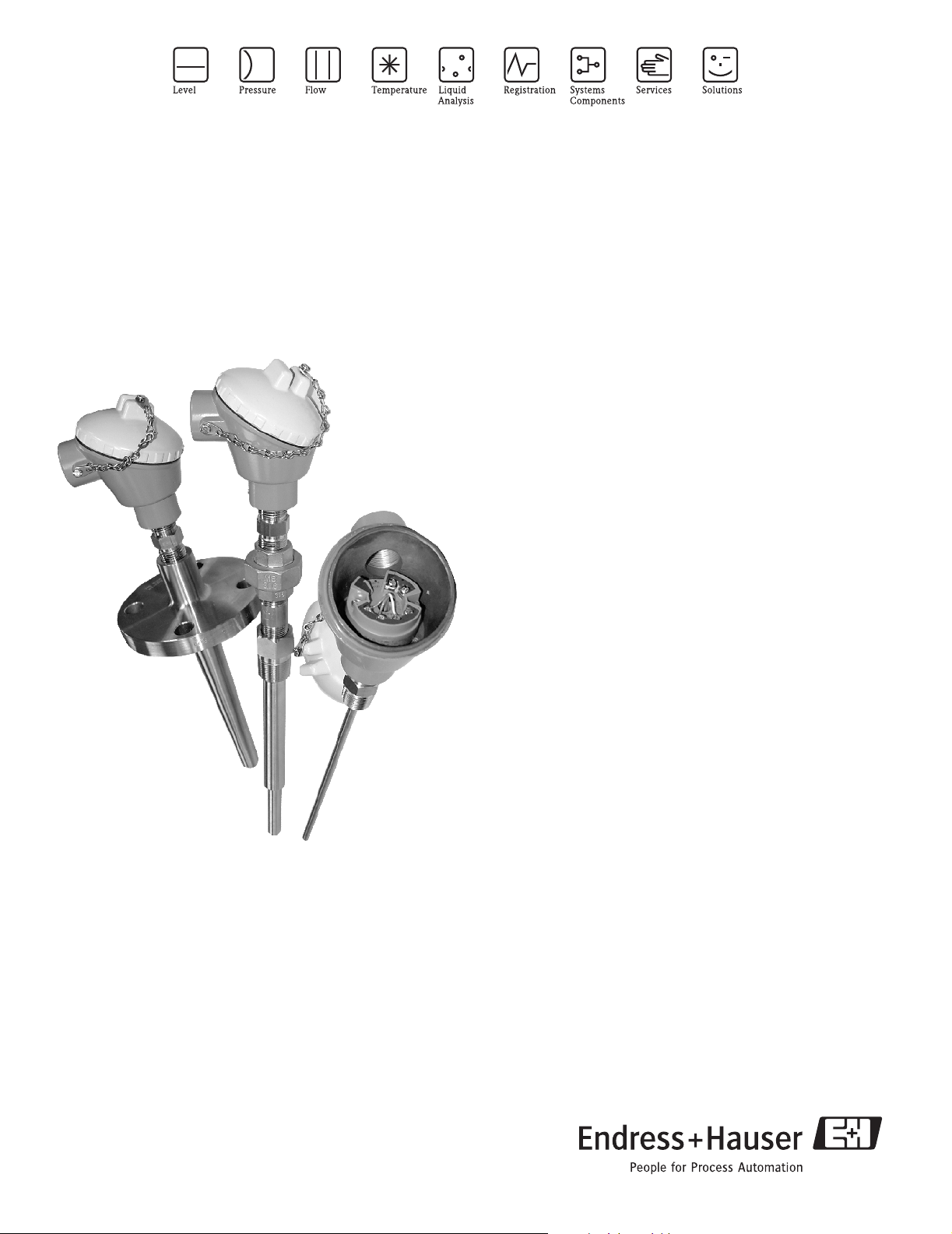
RTD TH13, TH14 and TH15
RTD assemblies in Thermowells with spring loaded insert and
enclosure for process industry
Areas of application
The TH13, TH14 and TH15 temperature sensors are RTD
assemblies installed in Thermowells and designed for use in
all types of process industries, including harsh environments,
due to their rugged design.
The sensor is made up of a measurement probe with an
insulated RTD element, sheath and a thermowell made of
bar-stock material.
The sensor assemblies can be used in process industries such
as:
• Chemicals
• Petrochemical
• Power plants
• Refineries
• Offshore Platforms
Head transmitters
Instead of directly wiring your temperature sensors to your
control system, use transmitters to reduce wiring and
maintenance costs while increasing measurement accuracy.
Field transmitters
Temperature field transmitters with HART
FOUNDATION Fieldbus™ protocol for highest reliability in
harsh industrial environments. Blue backlit display with large
measured value, bargraph and fault condition indication for
ease of reading.
Your benefits
• One source shopping for temperature measurement
solutions. World class transmitter with integrated sensor
offering for heavy process industry applications.
• Remove and install straight out of the box!
• Improved galvanic isolation on most devices (2 kV)
• Simplified model structure: Competitively priced, offers
great value. Easy to order and reorder. A single model
number includes sensor, thermowell and transmitter
assembly for a complete point solution
• All iTEMP
stability ≤ 0.05 % per year
®
transmitters provide long term
®
or
TI110R/24/ae
Page 2

TH13, TH14, TH15
Function and system design
Measuring principle The RTD (Resistance Temperature Detector) element consists of an electrical resistance with a value of 100 Ω
at 0 °C (called Pt100, in compliance with IEC 60751), which increases at higher temperatures according to a
coefficient characteristic of resistor material (platinum). In industrial thermometers that comply with the
IEC 60751 standard, the value of this coefficient is α = 0.00385 °C
(32 and 212 °F).
Measuring system
-1
, calculated between 0 and 100 °C
Example of an application of the temperature assemblies
Water - heat Differential
Calculation of heat quantity which is emitted or absorbed by a water flow in a heating or cooling system. The quantity of
heat is calculated from the process variable for ∆p flow (Q) and the differential from the feed and return temperature
(T
- T1). Bidirectional energy calculations, such as the calculating systems with changing flow direction (charging/
2
discharging the heat accumulator) are also possible.
Energy manager RMS621
Energy conservation and cost expenditures are significant issues in today's industry. Accurate flow monitoring
and calculation is the basis for thorough analysis and billing of energy. This data can serve as a basis to maximize
savings potential and help in controlling operational costs on a daily basis. Endress+Hauser's energy managers
provide accurate and reliable calculations for the monitoring and control of energy consumption (both
produced and consumed) according to international standards, e.g. IAPWS-IF 97, AGA8, ISO 5167 etc. For
RMS621 details see Technical Information.
®
iTEMP
TMT162 Temperature Field Transmitter
Aluminum or stainless steel dual compartment explosion - proof enclosure and compact, fully potted
electronics provide the ultimate protection in harshest environments. TMT162 prevents costly plant
shutdowns by detecting corrosion on RTDs or thermocouples before it corrupts the measured value.
Endress+Hauser's Field Temperature Transmitters with backlit display and sensor backup functionality are
designed with safety in mind to keep your plant, equipment and personnel safe. For TMT162 details see
Technical Information.
Deltabar S/Cerabar S
The evolution series of Cerabar S/Deltabar S represents a decisive step ahead in making pressure
instrumentation better and safer for the process industry. The development of new products thrives especially
on the knowledge, commitment and experience of staff members. Permanent high performance can only be
achieved if dedicated and enthusiastic people provide their ideas. Endress+Hauser's instruments are not only
supposed to distinguish themselves for customers and users by technological novelties but also by the presence
of people supporting this progress, be it in service, sales or production. For Deltabar S & Cerabar S details see
Technical Information.
2 Endress+Hauser
Page 3
TH13, TH14, TH15
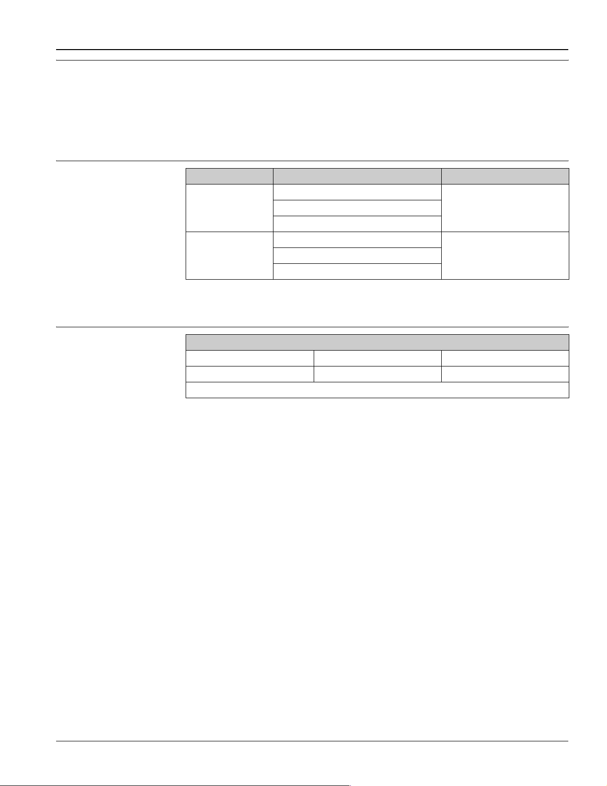
Equipment architecture The single and duplex element RTDs are designed to measure temperature in a variety of processes and
laboratory applications. These RTDs are specifically designed for use in two different process temperature
ranges and they will provide accurate and repeatable temperature measurement through a broad temperature
range of -328 to 1112 °F (-200 to 600 °C). Low range thin film RTDs -58 to 392 °F (-50 to 200 °C) are
constructed using silver plated and copper internal leads, PTFE wire insulations with potting compounds to
resist moisture penetration. High range RTDs -328 to 1112 °F (-200 to 600 °C) are constructed with nickel
internal leads inside swaged MgO insulated cables to allow higher temperature measurements at the RTD
element and to provide higher temperature lead protection along the sheath.
Measurement range
!
Calibration specifications
!
Construction Model code (class and type of sensor) max. range
TH13-_ _ _ _ _ (A/C/E/G/J/L) _ _ _ _ _
Low temperature range
TH15-_ _ _ (A/C/E/G/J/L) _ _ _ _ _
TH13-_ _ _ _ _ (B/D/F/H/K/M) _ _ _ _ _
High temperature range
TH15-_ _ _ (B/D/F/H/K/M) _ _ _ _ _ _
Note!
Options J, K, L, M are duplex platinum elements of two sensors inside the same sheath.
3 point sensor calibration
-40 to 0 °C 0 to 100 °C +40 to 215 °C
-40 to 32 °F 32 to 212 °F 104 to 420 °F
Minimum length requirements for calibrated sensors = 6"
Note!
Use option code ’B’ (Block: Test; calibration) for RTD calibration, the three temperature points need to be
specified in 5 °C (9 °F) increments.
The manufacturer provides comparison temperature calibrations from -40 to +215 °C (-40 to +420 °F) on the
international temperature scale of 1990. Calibrations are traceable to standards maintained by the national
institute of standards and technology (NIST). Calibration services are in conformance with ASTM E220, IEC
17025 and ANSI/NCSL Z540-1-1994. The report of calibration is referenced to the serial number of the RTD
assembly.
Three point calibrations are provided, given that the specified temperatures are within the recommended range
and the minimum length requirements are met as specified. The minimum length is based on overall length ’x’
of the spring loaded insert.
-58 to 392 °F (-50 to 200 °C)TH14-_ _ _ _ _ (A/C/E/G/J/L) _ _ _ _ _
-328 to 1112 °F (-200 to 600 °C)TH14-_ _ _ _ _(B/D/F/H/K/M) _ _ _ _ _
Endress+Hauser 3
Page 4

Electronics
TH13, TH14, TH15
Family of temperature transmitters
PC programmable devices TMT180 and TMT181
HART® TMT182 head
transmitter
Field transmitter TMT162 Dual compartment housing
Field transmitter TMT142 Single compartment housing
Measurement assemblies with iTEMP® transmitters are an installation ready solution to improve the
functionality of temperature measurement by increasing accuracy and reliability when compared to direct
wired sensors. Overall installation costs are lower than with direct wired sensors, since an inexpensive pair of
signal (4 to 20 mA) wires can be run over long distances.
PC programmable head transmitters offer you extreme flexibility and help control costs with the ability to stock
one device and program it for your needs. Regardless of your choice of output, all iTEMP
configured quickly and easily with a PC. To help you with this task, Endress+Hauser offers free software
ReadWin® 2000 which can be downloaded from our website. Go to www.readwin2000.com to download
ReadWin
HART® communication is all about easy, reliable data access and getting better information more
inexpensively. iTEMP
access to preventative diagnostic information.
Configuration with a DXR275 or 375 hand-held or a PC with configuration program (FieldCare, ReadWin®
2000) or configure with AMS or PDM. For details, see Technical Information.
Field transmitter with HART
Can be read easily from a distance, in sunlight and at night. Large measurement value, bargraph and fault
indication display. Benefits are: dual sensor input, highest reliability in harsh industrial environments,
mathematic functions, thermometer drift monitoring, sensor back-up functionality, corrosion detection and
sensor transmitter matching by accepting Callendar Van Dusen constants. For details, see Technical
Information.
Field transmitter with HART
of smaller transmitters with tiny display and old style analog transmitters. Large and brilliant blue backlit
display. Regardless of whether you install the transmitter in a dark location or in direct sunlight, you still get a
clear temperature reading. Reliable temperature measurement through advanced diagnostics. For details, see
Technical Information.
®
2000 today. For details see Technical Information.
®
transmitters integrate seamlessly into your existing control system and provide painless
®
communication, FOUNDATION Fieldbus™ protocol and blue backlit display.
®
communication. The one channel TMT142 allows for cost effective replacement
®
transmitters can be
PROFIBUS
transmitter
PA TMT184 head
Universally programmable head transmitter with PROFIBUS®-PA fieldbus communication. Converting various
input signals into a digital output signal. High accuracy in the total ambient temperature range. Swift and easy
operation, visualisation and maintenance using a PC direct from the control panel, e. g. using operating
software such as FieldCare, Simatic PDM or AMS. DIP switch for address setting, makes start up and
maintenance save and reliable. For details, see Technical Information.
®
Performance characteristics
Response time 63% response time per ASTM E644
RTD assembly TH15 without thermowell
Construction RTD insert ø ¼"
High temperature range 3 s
Low temperature range 9 s
!
Note!
Response time for the sensor assembly without transmitter.
4 Endress+Hauser
Page 5
TH13, TH14, TH15
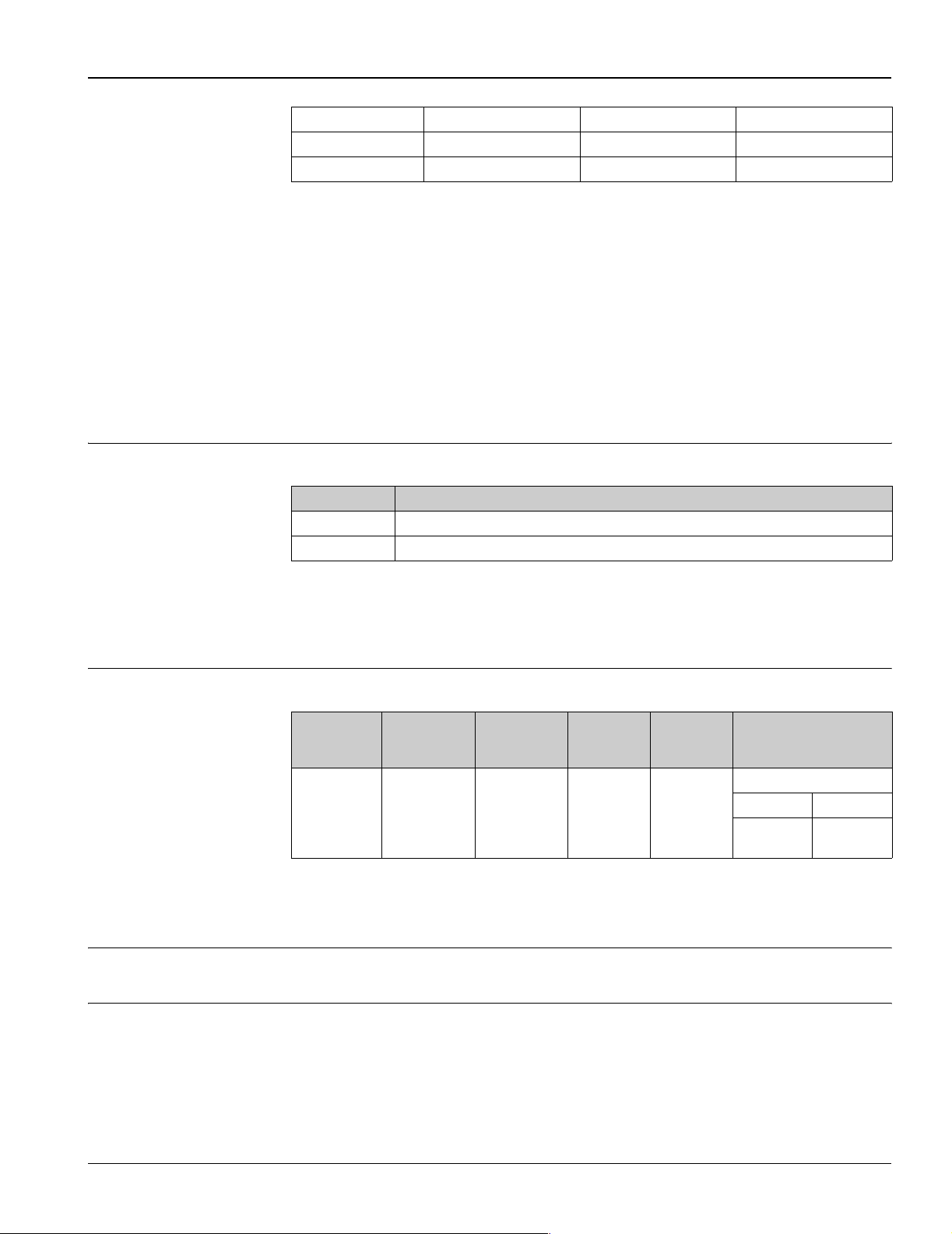
Response time examples for RTD assemblies with thermowell TH13 and TH14
Construction Stepped thermowell Tapered thermowell ¾" straight thermowell
High temperature range 20 s 25 s 30 s
Low temperature range 25 s 30 s 35 s
!
Note!
Response times for RTD assemblies with thermowell are provided for general design guidance without
transmitter
When the temperature of a process media changes, the output signal of a RTD assembly follows this change
after a certain time delay. The physical cause is the time related to heat transfer from the process media through
the thermowell and the insert to the sensor element (RTD). The manner in which the reading follows the
change in temperature of the assembly over time is referred to as the response time. Variables that influence
or impact the response time are:
• Wall thickness of thermowell
• Spacing between RTD insert and thermowell
• Sensor packaging
• Process parameters such as media, flow velocity, etc.
Maximum measured error RTD corresponding to IEC 60751
Class max. Tolerances (°C)
A ±(0.15 + 0.002 · |t|1), Temperature range: -100 °C to 450 °C
B ±(0.3 + 0.005 · |t|
1) |t| = absolute value °C
!
Note!
For measurement errors in °F, calculate using equation above in °C, then multiply the outcome by 1.8.
1
), Temperature range: -200 °C to 600 °C
Measurement accuracy transmitter
Transmitter long-term stabiltiy
TMT180
Pt100 PCP
0.36 °F (0.2 °C)
or 0.08%
1) % is related to the adjusted measurement range (the larger value applies)
2) % relates to the set span. Accuracy = digital + D/A accuracy
≤ 0.18 °F / year (≤ 0.1 °C/year) or ≤ 0.05% / year
Data under reference conditions; % relates to the set span. The larger value applies.
TMT181 multi-
functional PCP
0.36 °F (0.2 °C)
1
or 0.08%
0.36 °F (0.2 °C)
2
TMT182
®
HART
or 0.08%
2
TMT184
PROFIBUS
PA
0.27 °F
(0.15 °C)
TMT162 FF
®
-
Field trans-
mitter
0.18 °F
(0.1 °C)
Insulation resistance Insulation resistance between terminals and probe sheath, test voltage 250 V.
• ≥100 MΩ at 77 °F (25 °C)
• ≥10 MΩ at 572 °F (300 °C)
TMT142 and TMT162
®
HART
Field transmitter
Accuracy
Digital D/A
0.18 °F
(0.1 °C)
0.02%
2
Endress+Hauser 5
Page 6
TH13, TH14, TH15
Self heating RTD elements are not self-powered and require a small current be passed through the device to provide a
voltage that can be measured. Self-heating is the rise of temperature within the element itself, caused by the
current flowing through the element. This self-heating appears as a measurement error and is affected by the
thermal conductivity and velocity of the process being measured; it is negligible when an Endress+Hauser
®
temperature transmitter is connected.
iTEMP
®
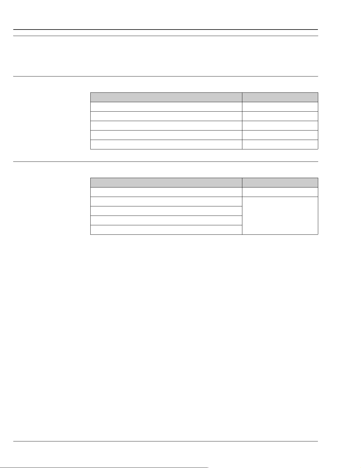
Sensor current Sensor current of Endress+Hauser iTEMP
Transmitter type Sensor current
TMT180 & TMT181 PCP ≤ 0.6 mA
TMT182 HART
TMT184 PROFIBUS
TMT162 HART
TMT142 HART® Field transmitter ≤ 0.3 mA
®
®
-PA ≤ 0.2 mA
®
, FF Field transmitter ≤ 0.3 mA
transmitters
≤ 0.2 mA
Galvanic isolation Galvanic isolation of Endress+Hauser iTEMP
Transmitter type Galvanic isolation
TMT181 PCP Û = 3.75 kV AC
TMT182 HART
TMT184 PROFIBUS®-PA
TMT162 HART®, FF Field transmitter
TMT142 HART
®
®
Field transmitter
®
transmitters (input/output)
U = 2 kV AC
6 Endress+Hauser
Page 7
TH13, TH14, TH15
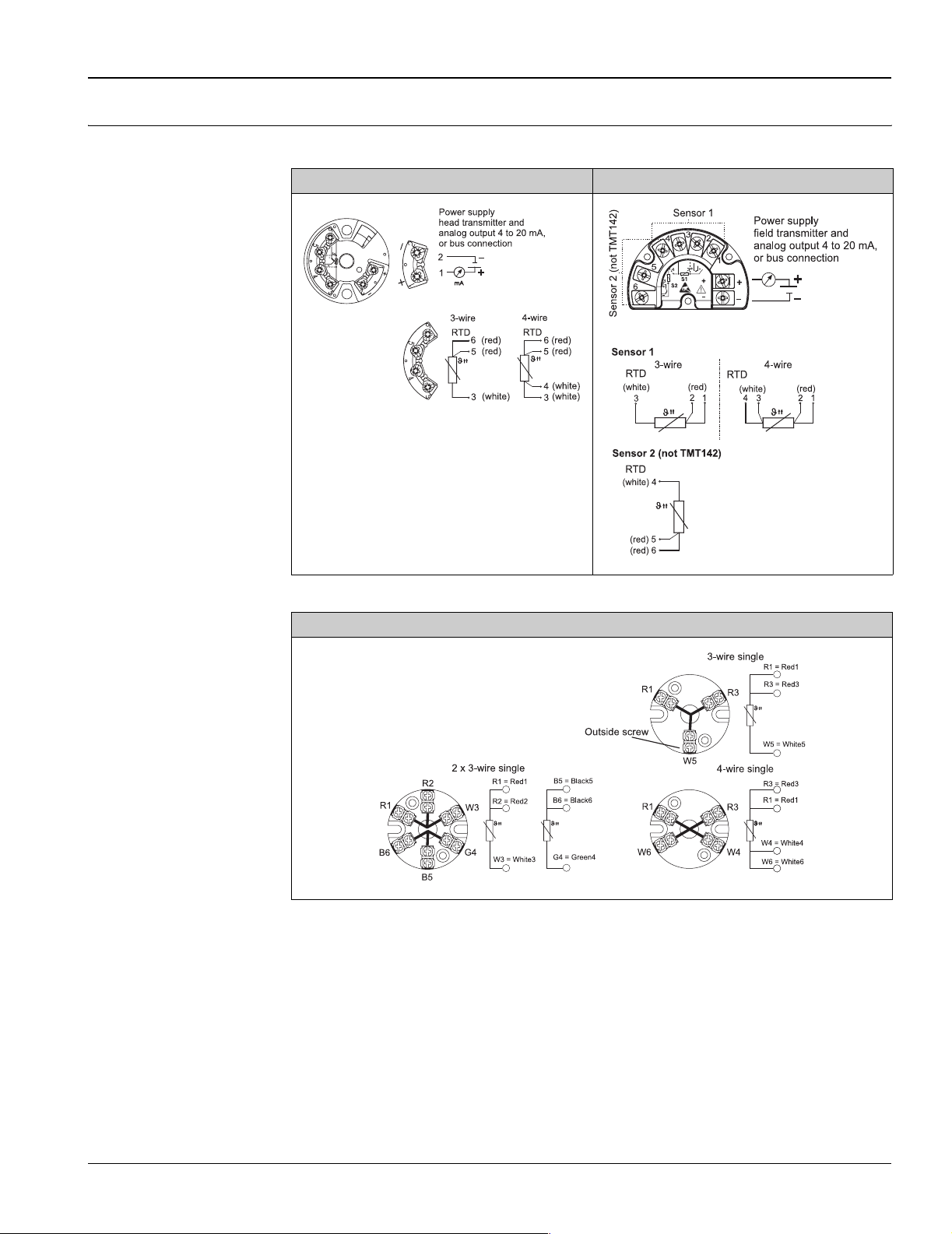
Wiring
Wiring diagrams Type of sensor connection
Head mounted transmitter Field mounted transmitter
!
T09-TH1112xx-04-xx-XX-ae-000
Terminal block mounted
Note!
The blocks and transmitters are shown as they sit inside the heads in reference to the conduit opening.
T09-TH131415-04-xx-xx-ae-000
T09-TH1112xx-04-xx-XX-ae-001
Endress+Hauser 7
Page 8
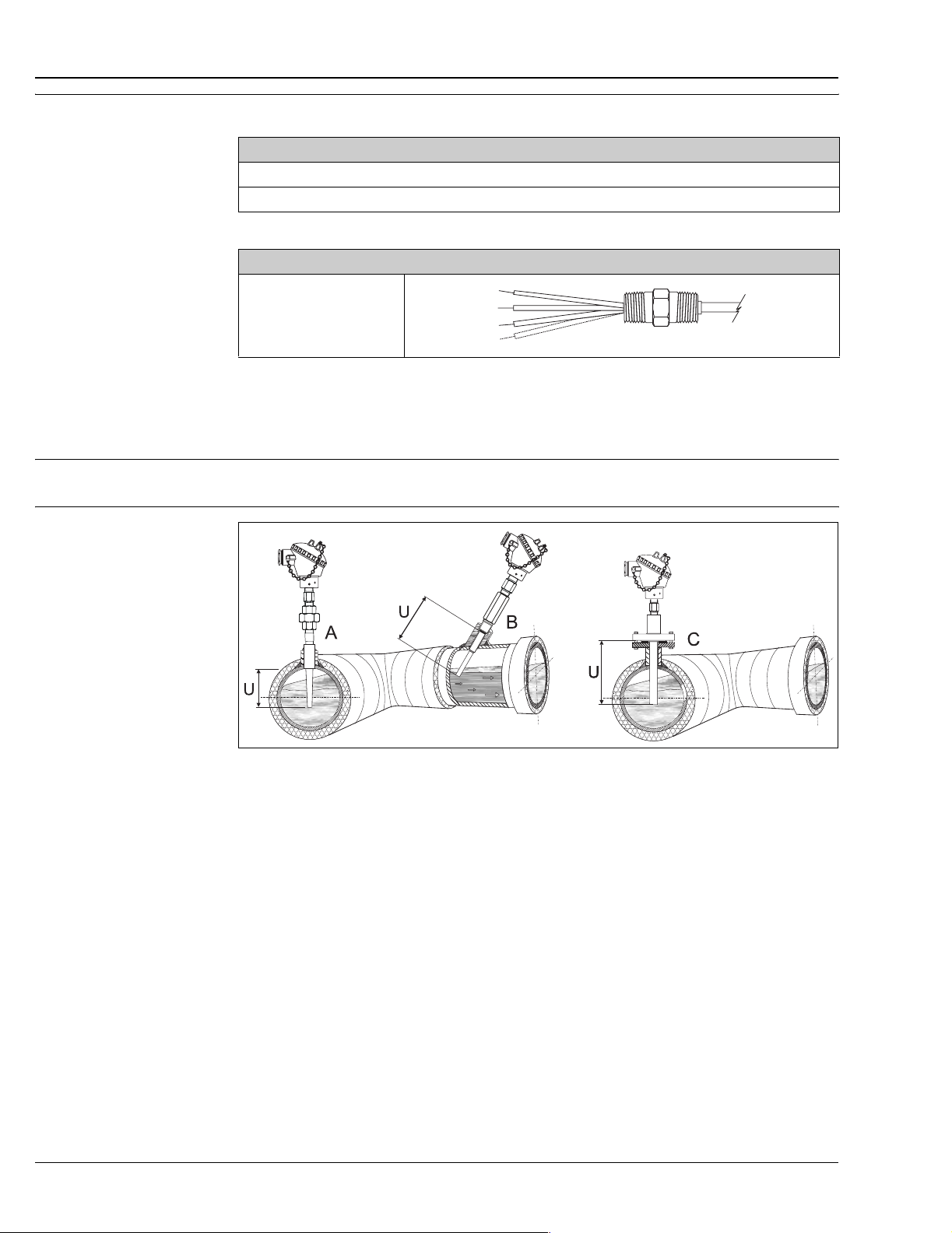
Wire specifications 24AWG, 19 strand silver plated copper with 0.010” PTFE extruded outer.
Electrical connection
Flying leads, standard 3" for wiring in connection head, head mounted transmitter or terminal block mounted
Flying leads, 5½" for wiring with TMT162 or TMT142 assemblies
Design of leads
Flying leads 3" or 5½" with
brass crimped sleeves
Installation conditions
Orientation No restrictions for installation orientation.
TH13, TH14, TH15
Installation instructions
T09-TH1314x15-11-xx-xx-ae-000
Examples for pipe installation - In pipes with a small cross section the sensor tip should reach or extend slightly past the
center line of the pipe (=U).
A: TH13 assembly socket weld installation
B: Threaded, tilted installation of TH13 assembly
C: Flange installation of TH14 assembly
8 Endress+Hauser
Page 9
TH13, TH14, TH15
Immersion
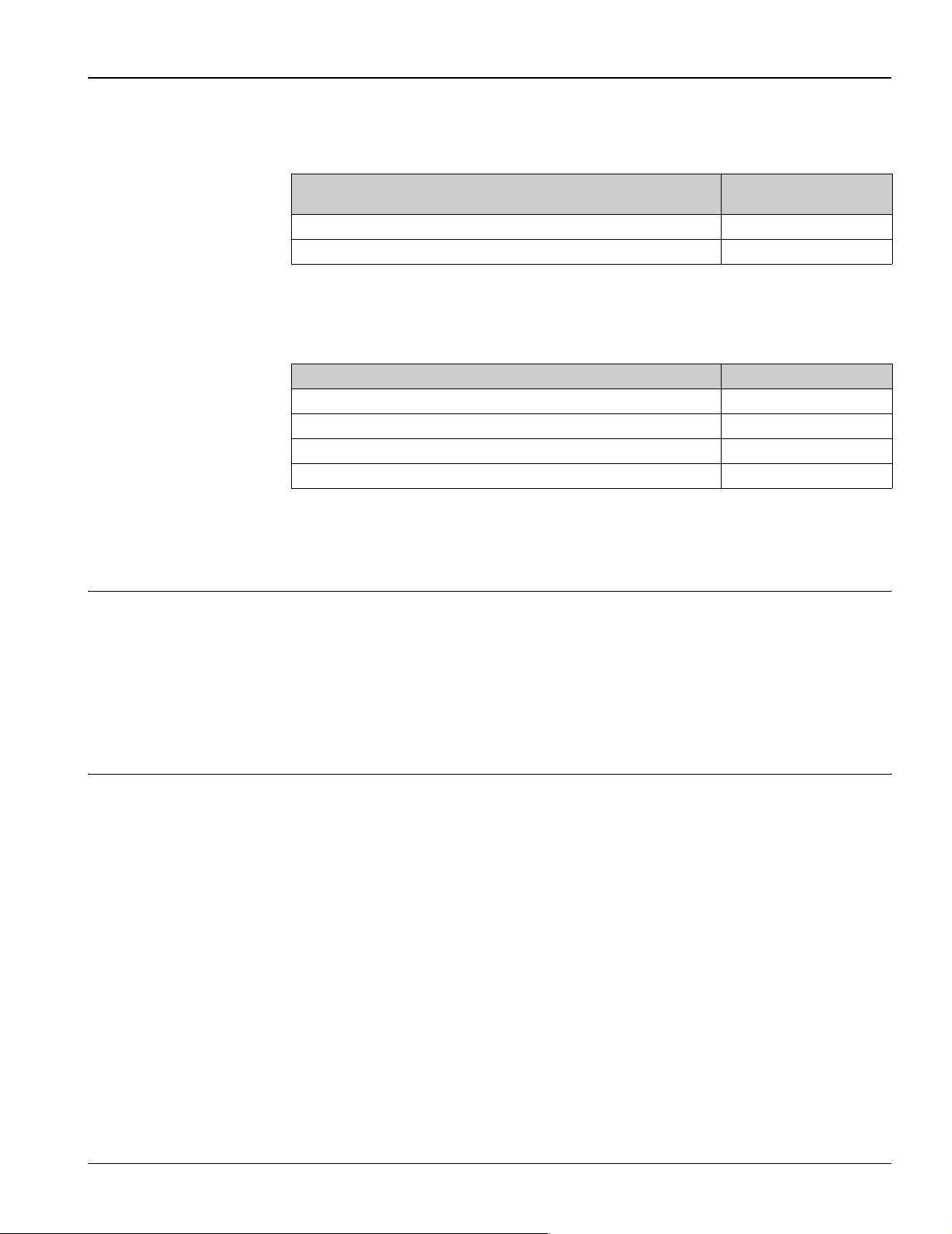
Minimum immersion per ASTM E644, ∆T ≤ 0.09 °F (0.05 °C)
Immersion RTD assembly TH15 without thermowell
Construction RTD Insert ø ¼"
Minimum Immersion (Inch)
High temperature range 1¼"
Low temperature range ¾"
For temperature assemblies with themowell (TH13 and TH14) the minimum immersion is the depth to which
the thermowell is immersed in the medium, measured from the tip. To minimize errors from ambient
temperature the following minimum immersion lengths are recommended:
Construction Minimum Immersion (Inch)
Stepped thermowell 2½"
Tapered thermowell 4½"
¾" straight thermowell 4"
Weld in thermowell 4½"
Environmental conditions
Ambient temperature Housing without head-mounted transmitter
• Aluminum pressure die-cast housing -40 to 300 °F (-40 to 150 ºC)
• Plastic housing -40 to 185 °F (-40 to 85 °C)
• Deep drawn SS housing without display -40 to 300 °F (-40 to 150 °C)
Housing with head-mounted transmitter
• -40 to 185 °F (-40 to 85 °C)
Field transmitter without display
• -40 to 185 °F (-40 to 85 °C)
Shock and vibration resistance 4g / 2 to 150 Hz as per IEC 60 068-2-6
Process conditions
Thermowells are used in measuring the temperature of a moving fluid in a conduit, where the stream exerts
an appreciable force. The limiting value for the thermowells is governed by the temperature, the pressure and
the speed of the medium, the immersion length, the materials of the thermowells and the medium, etc.
Calculations for stress and vibration of thermowells can be done according to ASME PTC 19.3-1974 standard,
please consult Endress+Hauser.
Endress+Hauser 9
Page 10
TH13, TH14, TH15
Mechanical construction
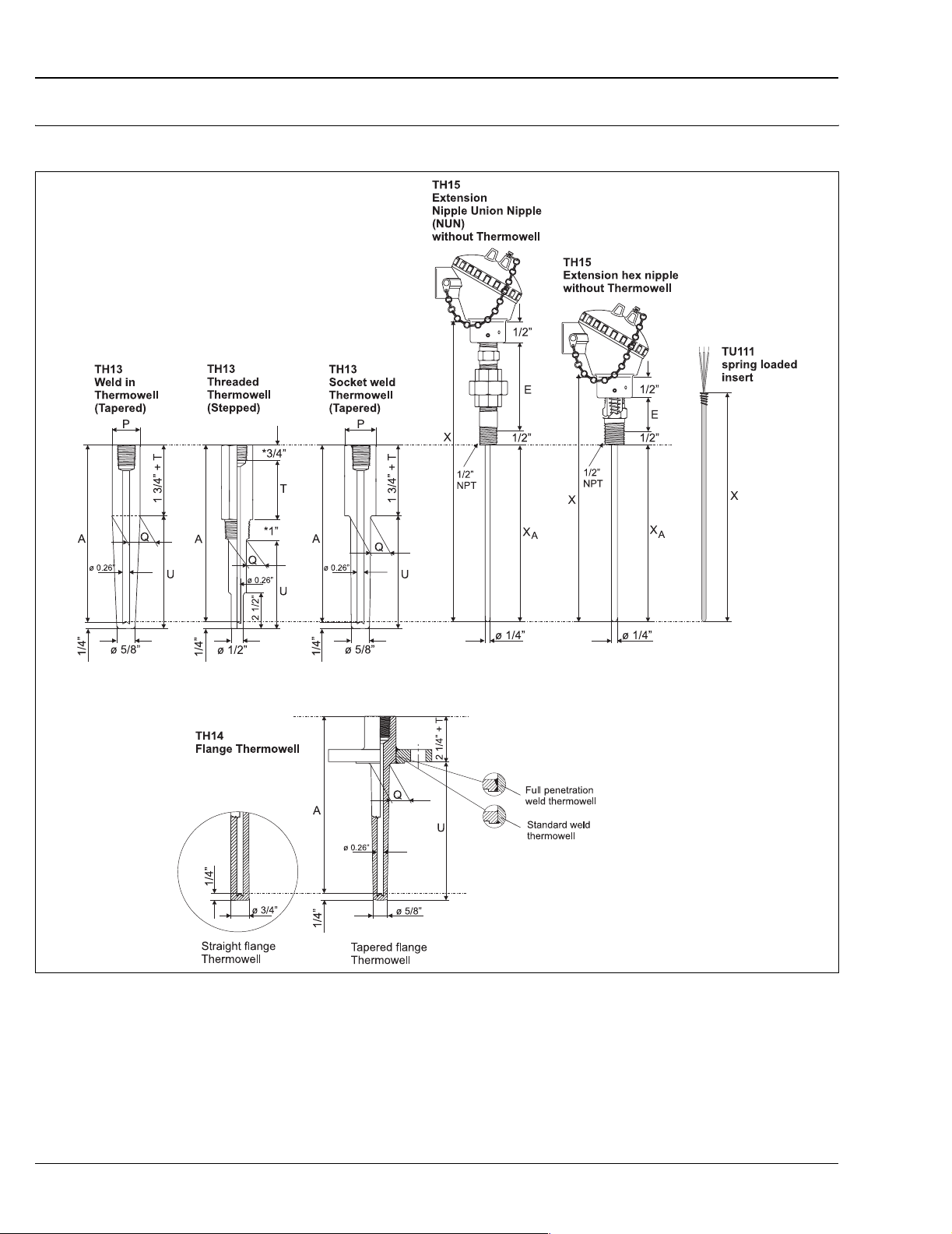
Design, dimensions All dimensions in inches. For the values related to this graphic please refer to the tables and equations below.
T09-TH131415-06-xx-xx-ae-000
*For TH13 thermowells with ½"NPT - 1" Process thread length and ¾" Hex length dimensions are reversed.
Pos. P: Pipe size
Pos. Q: Thermowell diameter
Pos. T: Lag dimension (see product structure)
Pos. U: Thermowell immersion length
Pos. X
, A: Immersion length RTD sensor; Thermowell drilled length
A
Pos. X: Insert overall length
10 Endress+Hauser
Page 11
TH13, TH14, TH15
All thermowells are marked with:
• Material I.D.
• CRN# (Canadian Registration Number)
•Heat No.
Dimensions of TH13
U E T Process
2½", 4½", 7½",
10½"
specified length
2" to 18" in
½" increments
Hex nipple = 1"
or
Nipple Union
Nipple
(NUN) = 4" or 7"
3" or
specified length
1" to 6" in
½" increments
Material:
Steel or 316SS
Immersion length RTD sensor = Thermowell drilled length X
Insert overall length X = A + E + 1"
P = Pipe size
• Nom. ¾"; Dia. = 1.050"
• Nom. 1"; Dia. = 1.315"
connection
½" NPT Stepped (Standard duty)
¾" NPT Stepped (Standard duty)
1" NPT Stepped (Standard duty)
¾" Socket weld Stepped (Standard duty)
1" Socket weld Stepped (Standard duty)
¾" weld in Tapered (Heavy duty) 1.050"
1" weld in Tapered (Heavy duty) 1.315"
= A = U + 1½" + T
A
Shape of Thermowell ø Q
5/8"
Tapered (Heavy duty)
11
/16"
Tapered (Heavy duty)¾"7/8"
7/8"
Tapered (Heavy duty)
1
1
Tapered (Heavy duty)¾"¾"
7/8"
Tapered (Heavy duty)
1"
/16"
Dimensions of TH14
Flange rating: ASME B16.5
U E T Flange size ø Q, Tapered
2", 4", 7", 10"
specified length
2" to 18"
in ½" increments
Immersion length RTD sensor - Thermowell drilled length X
Insert overall length X = A + E + 1"
Dimensions of TH15 (without Thermowell)
Immersion length RTD sensor X
4", 6", 9", 12", 14"
specified length 4" to 30" in ½" increments
Weight From 1 to 10 lbs
Hex nipple = 1"
or
Nipple Union
Nipple
(NUN) = 4" or 7"
Material:
Steel or 316SS
A
specified length
1" to 10" in
½" increments
1" 7/8"
1½" 1
2" 11/16"
= A = U + 2" + T
A
E
Hex nipple = 1"
or
Nipple Union Nipple (NUN) = 4" or 7"
version
1
/16"
Endress+Hauser 11
Page 12
Material Wetted parts 316SS
Thermowell material
Wetted parts 316SS for usage up to 1700 °F (927 °C). 316SS has good oxidation and corrosion resistance in a
wide range of industrial environments with improved resistance to mild acid and pitting corrosion. Exposure
to carbide precipitation, reduces corrosion resistance in the 800 to 1000 °F (427 to 538 °C) temperature range.
Good mechanical properties for -300 to 1450 °F (-184 to 788 °C) temperature range. Generally regarded as
standard protection tube material, other materials are available upon request.
System components
Housing
Type of housing Specification
Connection head Aluminum
• Material: Die-cast Aluminum head
• Sensor connection: ½" NPT Female
• Cable entry: ½" NPT or ¾" NPT Female. ½" NPT has a Al reducer bushing
• Body paint: Spray SPU, RAL5012
Cover paint: Spray SPU, RAL7035
• Coating thread (body-cover), lubricant acc. E+H standard, MgO coating;
benefits include ease of opening/closing cover and improved thread
engagement. Improves lifetime of the connection head.
• Degree of protection NEMA 4X (IP 66)
TH13, TH14, TH15
Connection head plastic
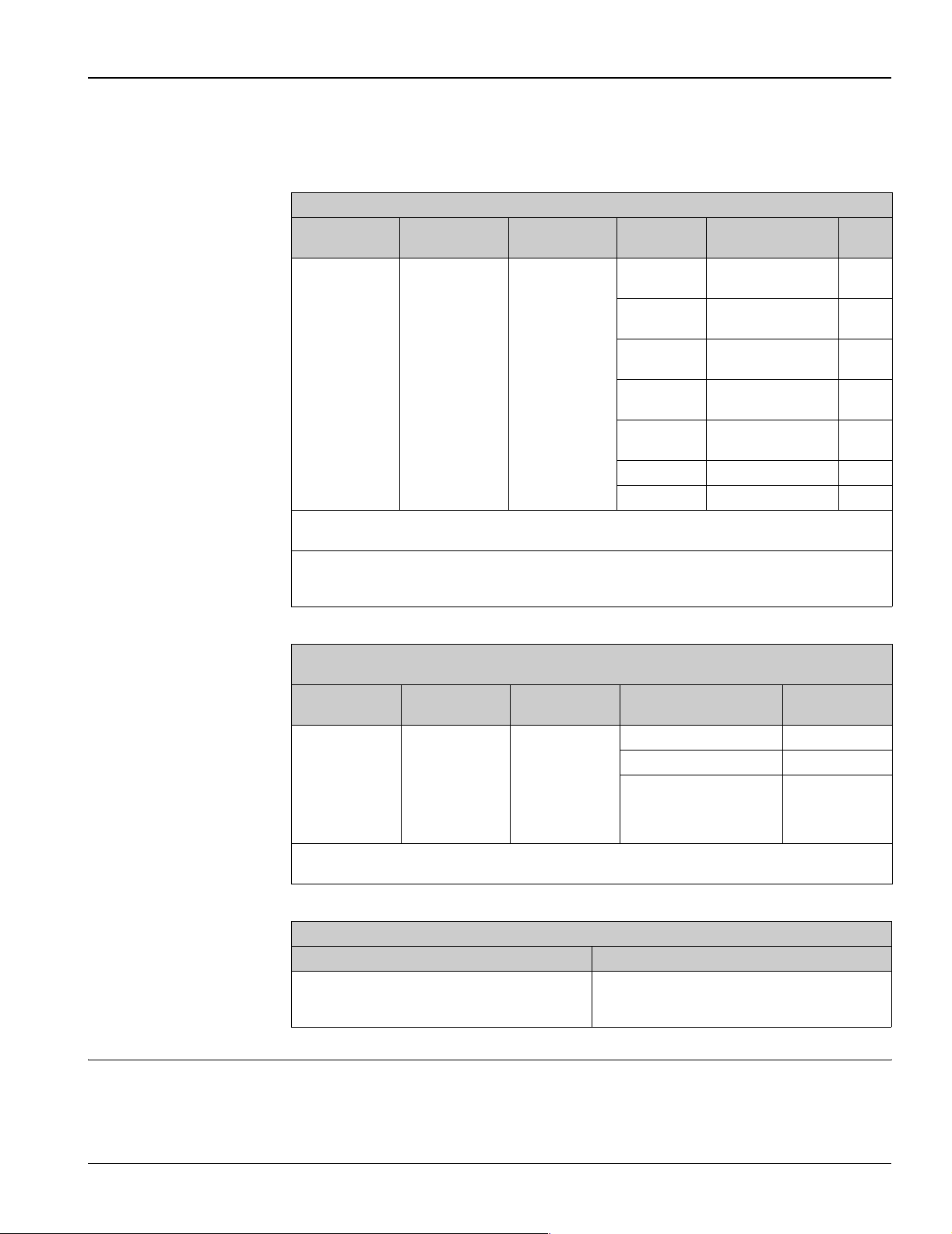
Temperature field transmitter iTEMP
®
TMT162
T09-TH11xxxx-06-xx-xx-ae-001
• Polyprolylene, FDA compliant
• Sensor connection: ½" NPT Female
• Cable entry: ½" NPT or ¾" NPT Female. ½" NPT with nylon reducer bushing
(FDA compliant)
• Degree of protection NEMA 4X
T09-TH11xxxx-06-xx-xx-ae-000
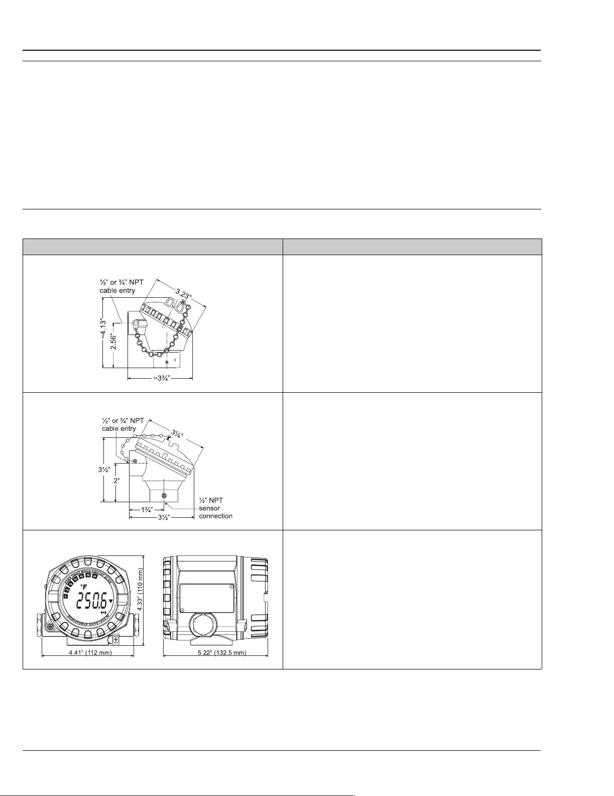
• Material: Die-cast aluminum housing AlSi10Mg with powder coating on
polyester base
• Separate electronics compartment and connection compartment
• Display rotatable in 90° increments
• Cable entry: 2 x ½" NPT
• Degree of protection NEMA 4X (IP 67)
• Brilliant blue backlit display with ease of visibility in bright sunshine or pitch
darkness
• Gold plated terminals to avoid corrosion and additional measurement errors
Details see Technical Information (see 'Documentation')
T09-TMT162ZZ-06-00-xx-ae-001
12 Endress+Hauser
Page 13
TH13, TH14, TH15
Type of housing Specification
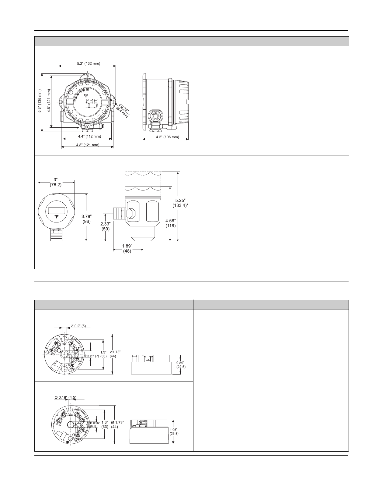
Temperature field transmitter iTEMP® HART® TMT142
T09-TMT142ZZ-06-00-06-ae-001
Connection head deep drawn stainless steel, TA20J style
• Material: Die-cast aluminum housing AlSi10Mg with powder coating on
polyester base
• Display rotatable in 90° increments
• Cable entry: 3 x ½" NPT
• Degree of protection NEMA 4X (IP 67)
• Brilliant blue backlit display with ease of visibility in bright sunshine or pitch
darkness
• Gold plated terminals to avoid corrosion and additional measurement errors
Details see Technical Information (see 'Documentation')
• Material: Deep drawn stainless steel AISI 316L SS (hygienic design)
• Optional with display and/or head transmitter
• Sensor connection: ½" NPT female
• Cable entry: ½" NPT female
• Degree of protection NEMA 4X (IP 66)
Display:
• 4 digits 7-segments LC display (loop powered)
• Maximum error: 0.1% of programmed range
• Loop drop: 2.5 V at 22 mA
• Max. ambient temperature: -4 to 160 °F (-20 to 70 °C)
The programming is executed through 3 keys mounted on the bottom of the
display.
a0005938
* dimensions with optional display
Head transmitter
Type of transmitter) Specification
®
iTEMP
iTEMP
TMT18x
®
PA TMT184
R09-TMT182ZZ-06-06-xx-ae-001
•Material
Housing: PC
Potting: PUR
• Terminals: Cable up to max. 16 AWG (secure screws) or with wire end
ferrules
• Eyelets for easy connection of a HART
clips
• Degree of protection NEMA 4 (see also type of connection head)
Details see Technical Information (see ’Documentation’)
®
-handheld terminal with alligator
T09-TMT184ZZ-06-06-xx-ae-001
Endress+Hauser 13
Page 14
TH13, TH14, TH15
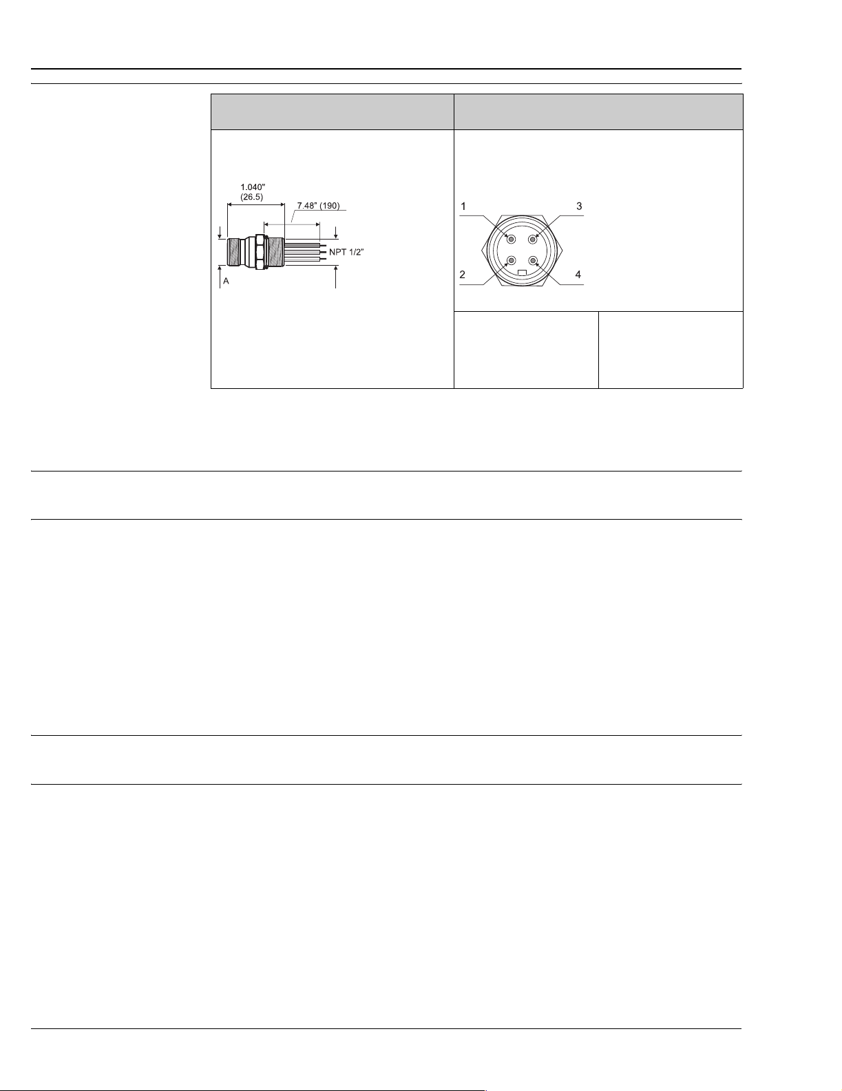
Fieldbus connector
Type (dimensions in inches [mm]) Specification
Fieldbus connector to PROFIBUS
FOUNDATION Fieldbus™
Pos. A:
M12 on PROFIBUS
7/8-16 UNC on FOUNDATION Fieldbus™
connector
®
-PA connector
®
-PA or
T09-FFCONNEC-06-xx-x x-ae-000
• Ambient temperature: -40 to 300 °F (-40 to 150 °C)
• Degree of protection IP 67
Wiring diagram:
PROFIBUS® -PA
Pos 1: grey (shield)
Pos 2: brown (+)
Pos 3: blue (-)
Pos 4: not connected
a0006023
FOUNDATION Fieldbus™
Pos 1: blue (-)
Pos 2: brown (+)
Pos 3: not connected
Pos 4: ground (green/yellow)
Certificates and approvals
CE Mark The iTEMP® Series of temperature transmitters complies with the legal requirements laid out within the EU
regulations.
Other standards and
guidelines
• IEC 60529:
Degrees of protection by housing (IP-Code).
• IEC 61010:
Safety requirements for electrical measurement, control and laboratory instrumentation.
• ASTM E644:
American society for testing and materials, standard test methods for testing industrial
resistance thermometers.
• NEMA - ANSI / NEMA 250
Standardization association for the electrical industry.
• IEC 60571
Industrial platinum resistance thermometer
• ASME PTC 19.3 - 1974
Performance test codes
UL Temperature transmitters are recognized components to UL 3111-1 (iTEMP
PROFIBUS
CSA GP The installed and assembled transmitters (iTEMP
®
-PA.
®
Series) are CSA GP approved, except TMT184 PROFIBUS®
PA
®
Series) except for TMT184
14 Endress+Hauser
Page 15
TH13, TH14, TH15
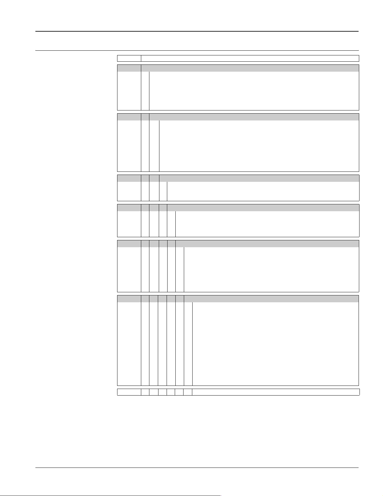
Ordering information
Product structure, RTD assembly in thermowell TH13
TH13- RTD assembly in thermowell, TH13
TW Immersion length U:
1 2½ inch
2 4½ inch
3 7½ inch
4 10½ inch
8 .... inch (0.5" increments)
Y special
Process connection, TW Material, 1 inch:
A1 ½" NPT 316SS
A2 ¾" NPT 316SS
A3 1" NPT 316SS
B1 Socket weld ¾" 316SS
B2 Socket weld 1" inch 316SS
C1 Weld in ¾" 316SS
C2 Weld in 1" inch 316SS
YY Special
Shape of TW:
2 Stepped, Standard Duty
3 Tapered, Heavy Duty
9 Special
Lag of TW T:
A None
E 3 inch
X ... inch (0.5" increments)
Y Special
Extension:
1 Hex nipple 316SS, E=1"
2 Nipple Union Nipple 316SS, E=4"
3 Hex nipple steel, E=1"
4 Nipple Union Nipple, steel, E=4"
5 Nipple Union Nipple, steel, E=7"
6 Nipple Union Nipple, 316SS, E=7"
9 Special
Class; Type Sensor IEC751; Connection:
A 1 Pt100 class B, 3 wire low, -50 to 200 °C (-58 to 392 °F)
B 1 Pt100 class B, 3 wire high, -200 to 600 °C (-328 to 1112 °F)
C 1 Pt100 class A, 3 wire low, -50 to 200 °C (-58 to 392 °F)
D 1 Pt100 class A, 3 wire high, -200 to 600 °C (-328 to 1112 °F)
E 1 Pt100 class B, 4 wire low, -50 to 200 °C (-58 to 392 °F)
F 1 Pt100 class B, 4 wire high, -200 to 600 °C (-328 to 1112 °F)
G 1 Pt100 class A, 4 wire low, -50 to 200 °C (-58 to 392 °F)
H 1 Pt100 class A, 4 wire high, -200 to 600 °C (-328 to 1112 °F)
J 2 Pt100 class B, 3 wire low, -50 to 200 °C (-58 to 392 °F)
K 2 Pt100 class B, 3 wire high, -200 to 600 °C (-328 to 1112 °F)
L 2 Pt100 class A, 3 wire low, -50 to 200 °C (-58 to 392 °F)
M 2 Pt100 class A, 3 wire high, -200 to 600 °C (-328 to 1112 °F)
Y Special
TH13- ← Order code (Part 1)
Endress+Hauser 15
Page 16
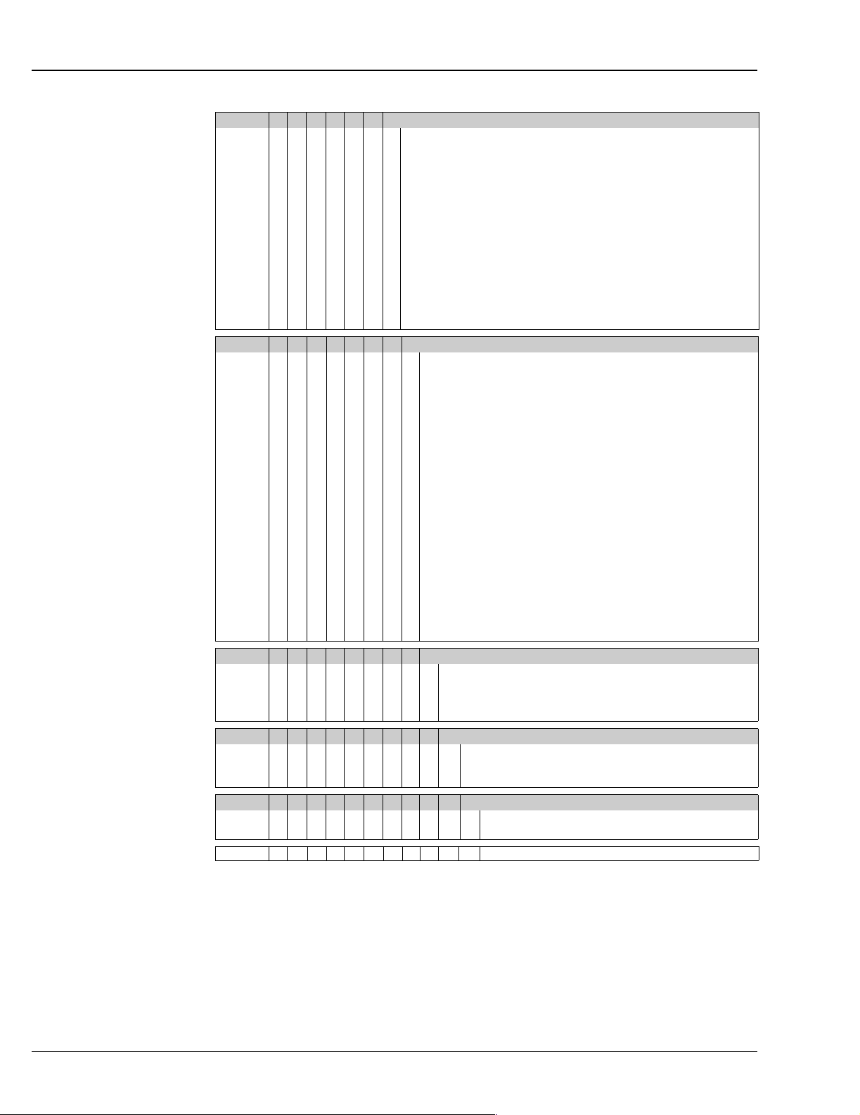
Enclosure; communication:
A None
B E+H blue Al + cover, ½" NPT cable entry
C E+H blue Al + cover, ¾" NPT cable entry
D Plastic PP white ½" NPT cable entry
E Plastic PP white ¾" NPT cable entry
F SS316L (TA20J), ½" NPT
G SS316L (TA20J), LCD, ½" NPT
H AL Field Housing, 1 Input, ½" NPT, HART
I AL Field Housing, 1 Input, Display, HART, ½" NPT
J AL Field Housing, 2 Input, ½" NPT, HART
K AL Field Housing, 2 Input, Display, HART, ½" NPT
L AL Field Housing, 2 Input, ½" NPT, FF
M AL Field Housing, 2 Input, Display, FF, ½" NPT
Y Special
Electrical connection:
A Programmable RTD TMT180
C Programmable TMT181 NON Ex
D Programmable TMT181 FM IS
E Programmable TMT181 CSA IS
F Profibus PA TMT184, non Ex
G Profibus PA TMT184, FM IS
H Profibus PA TMT184, CSA IS
I TMT162, non Ex, Dual Compartment
J TMT162, FM IS, Dual Compartment
K TMT162, CSA IS, Dual Compartment
L HART TMT142 non Ex, Single Compartment
M HART TMT142, FM IS, Single Compartment
N HART TMT142, CSA IS, Single Compartment
O HART TMT182, FM IS Advanced Diagnostic
P HART TMT182 NON Ex
R HART TMT182 FM IS
T HART TMT182 CSA IS
Y Special
2 Flying Leads
3 Terminal block
Additional option:
1 None
2 Profibus PA Plug M12
3 Foundation Fieldbus Plug 7/8"
9 special version
Test; Calibration:
A None
B Sensor calibration certificate
Y Special version
Model:
K Standard model, North American region
Y Special version
TH13- ← Order code (complete)
TH13, TH14, TH15
16 Endress+Hauser
Page 17
TH13, TH14, TH15
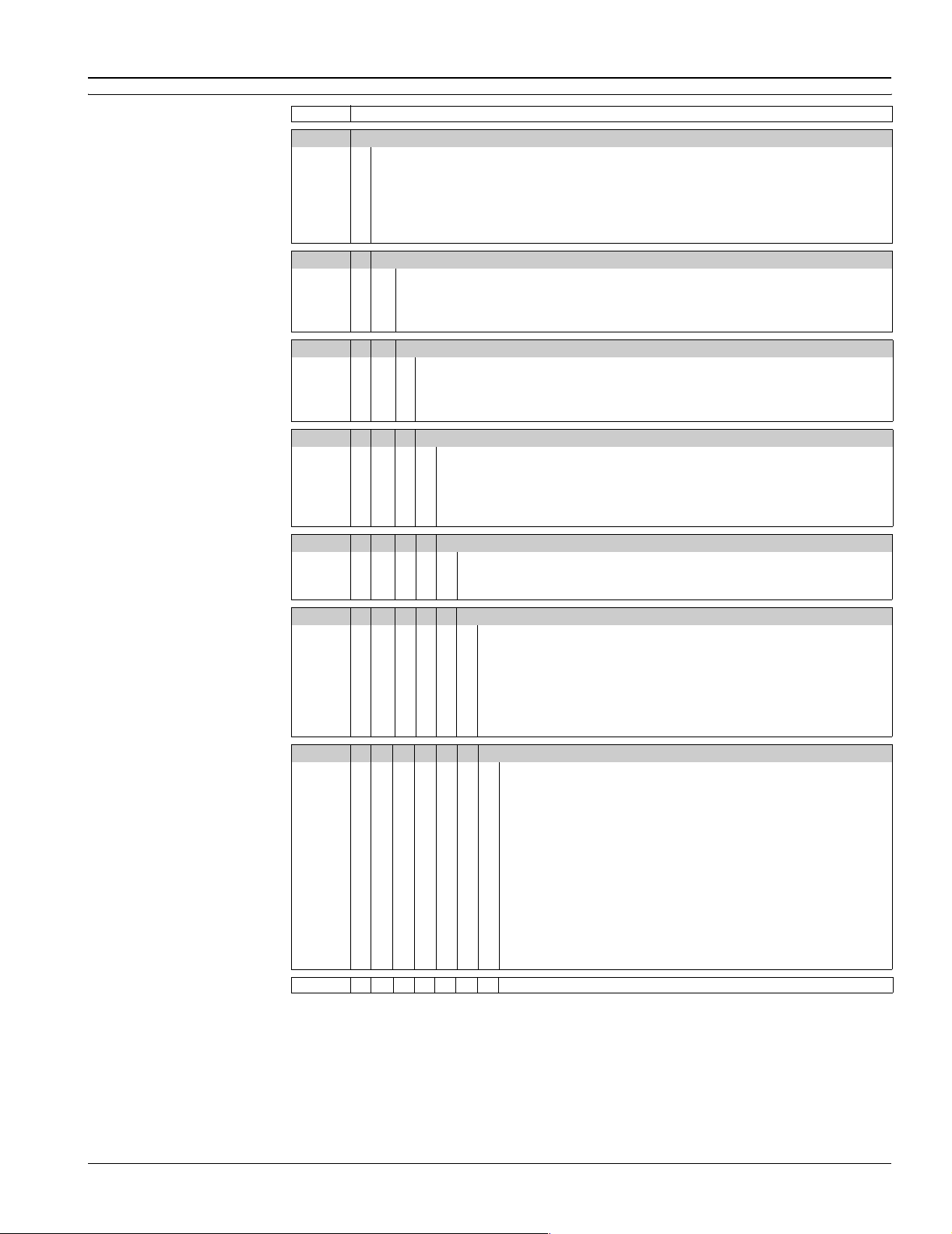
Product structure, RTD assembly in flanged thermowell TH14
TH14- RTD assembly in flanged thermowell, TH14
TW Immersion length U
1 2 inch
2 4 inch
3 7 inch
4 10 inch
8 .... inch (0.5" increments)
Y Special version
Flange size; TW Material per 1 inch:
A 1 inch 316SS
B 1½ inch 316SS
C 2 inch 316SS
Y Special
Rating; Type:
1 150 psi; RF
2 300 psi; RF
3 600 psi; RF
9 Special
Shape of TW; Welding:
1 Straight; standard
2 Tapered; standard
3 Straight; full penetration
4 Tapered; full penetration
9 Special
Lag of TW, T:
A None
X .... inch (0.5" increments)
Y Special
Extension:
1 Hex nipple 316SS, E=1"
2 Nipple Union Nipple 316SS, E=4"
3 Hex nipple steel, E=1"
4 Nipple Union Nipple, steel, E=4"
5 Nipple Union Nipple, steel, E=7"
6 Nipple Union Nipple, 316SS, E=7"
9 Special
Class; Type Sensor IEC751; Connection:
A 1 Pt100 class B, 3 wire low, -50 to 200 °C (-58 to 392 °F)
B 1 Pt100 class B, 3 wire high, -200 to 600 °C (-328 to 1112 °F)
C 1 Pt100 class A, 3 wire low, -50 to 200 °C (-58 to 392 °F)
D 1 Pt100 class A, 3 wire high, -200 to 600 °C (-328 to 1112 °F)
E 1 Pt100 class B, 4 wire low, -50 to 200 °C (-58 to 392 °F)
F 1 Pt100 class B, 4 wire high, -200 to 600 °C (-328 to 1112 °F)
G 1 Pt100 class A, 4 wire low, -50 to 200 °C (-58 to 392 °F)
H 1 Pt100 class A, 4 wire high, -200 to 600 °C (-328 to 1112 °F)
J 2 Pt100 class B, 3 wire low, -50 to 200 °C (-58 to 392 °F)
K 2 Pt100 class B, 3 wire high, -200 to 600 °C (-328 to 1112 °F)
L 2 Pt100 class A, 3 wire low, -50 to 200 °C (-58 to 392 °F)
M 2 Pt100 class A, 3 wire high, -200 to 600 °C (-328 to 1112 °F)
Y Special
TH14- ← Order code (Part 1)
Endress+Hauser 17
Page 18
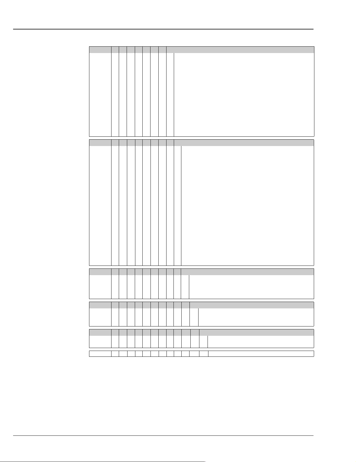
Enclosure; communication:
A None
B E+H blue Al + cover, ½" NPT cable entry
C E+H blue Al + cover, ¾" NPT cable entry
D Plastic PP white ½" NPT cable entry
E Plastic PP white ¾" NPT cable entry
F SS316L (TA20J), ½" NPT
G SS316L (TA20J), LCD, ½" NPT
H AL Field Housing, 1 Input, ½" NPT, HART
I AL Field Housing, 1 Input, Display, HART, ½" NPT
J AL Field Housing, 2 Input, ½" NPT, HART
K AL Field Housing, 2 Input, Display, HART, ½" NPT
L AL Field Housing, 2 Input, ½" NPT, FF
M AL Field Housing, 2 Input, Display, FF, ½" NPT
Y Special
Electrical connection:
A Programmable RTD TMT180
C Programmable TMT181 NON Ex
D Programmable TMT181 FM IS
E Programmable TMT181 CSA IS
F Profibus PA TMT184, non Ex
G Profibus PA TMT184, FM IS
H Profibus PA TMT184, CSA IS
I TMT162, non Ex, Dual Compartment
J TMT162, FM IS, Dual Compartment
K TMT162, CSA IS, Dual Compartment
L HART TMT142 non Ex, Single Compartment
M HART TMT142, FM IS, Single Compartment
N HART TMT142, CSA IS, Single Compartment
O HART TMT182, FM IS Advanced Diagnostic
P HART TMT182 NON Ex
R HART TMT182 FM IS
T HART TMT182 CSA IS
Y Special
2 Flying Leads
3 Terminal block
Additional option:
1 None
2 Profibus PA Plug M12
3 Foundation Fieldbus Plug 7/8"
9 special version
Test; Calibration:
A None
B Sensor calibration certificate
Y Special version
Model:
K Standard model, North American region
Y Special version
TH14- ← Order code (complete)
TH13, TH14, TH15
18 Endress+Hauser
Page 19

TH13, TH14, TH15
Product structure, RTD assembly TH15
TH15- RTD assembly, TH15
Immersion length X
1 4 inch
2 6 inch
3 9 inch
4 12 inch
5 14 inch
8 .... inch (0.5" increments)
Y Special version
A
Sheath diameter price per 2 inch:
A ¼ inch 316SS
Y Special
Extension:
1 Hex nipple 316SS, E=1"
2 Nipple Union Nipple 316SS, E=4"
3 Hex nipple steel, E=1"
4 Nipple Union Nipple, steel, E=4"
5 Nipple Union Nipple, steel, E=7"
6 Nipple Union Nipple, 316SS, E=7"
9 Special
Class; Type Sensor IEC751; Connection:
A 1 Pt100 class B, 3 wire low, -50 to 200 °C (-58 to 392 °F)
B 1 Pt100 class B, 3 wire high, -200 to 600 °C (-328 to 1112 °F)
C 1 Pt100 class A, 3 wire low, -50 to 200 °C (-58 to 392 °F)
D 1 Pt100 class A, 3 wire high, -200 to 600 °C (-328 to 1112 °F)
E 1 Pt100 class B, 4 wire low, -50 to 200 °C (-58 to 392 °F)
F 1 Pt100 class B, 4 wire high, -200 to 600 °C (-328 to 1112 °F)
G 1 Pt100 class A, 4 wire low, -50 to 200 °C (-58 to 392 °F)
H 1 Pt100 class A, 4 wire high, -200 to 600 °C (-328 to 1112 °F)
J 2 Pt100 class B, 3 wire low, -50 to 200 °C (-58 to 392 °F)
K 2 Pt100 class B, 3 wire high, -200 to 600 °C (-328 to 1112 °F)
L 2 Pt100 class A, 3 wire low, -50 to 200 °C (-58 to 392 °F)
M 2 Pt100 class A, 3 wire high, -200 to 600 °C (-328 to 1112 °F)
Y Special
Enclosure; communication:
A None
B E+H blue Al + cover, ½" NPT cable entry
C E+H blue Al + cover, ¾" NPT cable entry
D Plastic PP white ½" NPT cable entry
E Plastic PP white ¾" NPT cable entry
F SS316L (TA20J), ½" NPT
G SS316L (TA20J), LCD, ½" NPT
H AL Field Housing, 1 Input, ½" NPT, HART
I AL Field Housing, 1 Input, Display, HART, ½" NPT
J AL Field Housing, 2 Input, ½" NPT, HART
K AL Field Housing, 2 Input, Display, HART, ½" NPT
L AL Field Housing, 2 Input, ½" NPT, FF
M AL Field Housing, 2 Input, Display, FF, ½" NPT
Y Special
TH15- ← Order code (part 1)
Endress+Hauser 19
Page 20
Electrical connection:
A Programmable RTD TMT180
C Programmable TMT181 NON Ex
D Programmable TMT181 FM IS
E Programmable TMT181 CSA IS
F Profibus PA TMT184, non Ex
G Profibus PA TMT184, FM IS
H Profibus PA TMT184, CSA IS
I TMT162, non Ex, Dual Compartment
J TMT162, FM IS, Dual Compartment
K TMT162, CSA IS, Dual Compartment
L HART TMT142 non Ex, Single Compartment
M HART TMT142, FM IS, Single Compartment
N HART TMT142, CSA IS, Single Compartment
O HART TMT182, FM IS Advanced Diagnostic
P HART TMT182 NON Ex
R HART TMT182 FM IS
T HART TMT182 CSA IS
Y Special
2 Flying Leads
3 Terminal block
Documentation Requirement:
1 Standard
9 Other
Test; Calibration:
A None
B Sensor calibration certificate
Y Other
Model:
K Standard model, North American region
Y Other
Additional option:
1 None
2 Profibus PA Plug M12
3 Foundation Fieldbus Plug 7/8"
9 special version
TH15- ← Order code (complete)
TH13, TH14, TH15
20 Endress+Hauser
Page 21

TH13, TH14, TH15
Documentation
• Compact instructions TH13 RTD assembly in thermowell (KA190r/24/ae)
• Compact instructions TH14 RTD assembly in flanged thermowell (KA192r/24/ae)
• Compact instructions TH15 RTD assembly - spring loaded (KA195r/24/ae)
• Technical information Temperature field transmitter iTEMP
• Technical information Temperature field transmitter iTEMP® HART® TMT142 (TI107r/24/ae)
• Technical information Temperature head transmitter iTEMP
• Technical information Temperature head transmitter iTEMP® PCP TMT181 (TI070r/24/ae)
• Technical information Temperature head transmitter iTEMP® HART® TMT182 (TI078r/24/ae)
• Technical information Temperature head transmitter iTEMP
Application example:
• Technical information Energy manager RMS621 (TI092r/24/ae)
• Technical information Cerabar S (TI383r/24/ae)
• Technical information Deltabar S (TI384r/24/ae)
®
TMT162 (TI086r/24/ae)
®
Pt TMT180 (TI088r/24/ae)
®
PA® TMT184 (TI079r/24/ae)
Endress+Hauser 21
Page 22

TH13, TH14, TH15
Page 23

TH13, TH14, TH15
Page 24

TH13, TH14, TH15
United States
Endress+Hauser, Inc.
2350 Endress Place
Greenwood, IN 46143
Tel: 317-535-7138
Sales: 888-ENDRESS
Service: 800-642-8737
FAX: 317-535-8498
[email protected]
www.us.endress.com
TI110R/24/ae/06.06
FM+SGML 6.0 ProMoDo
Canada
Endress+Hauser Canada
1075 Sutton Drive
Burlington, ON L7L 5Z8
Tel: 905-681-9292
800-668-3199
FAX: 905-681-9444
www.ca.endress.com
Mexico
Endress+Hauser (Mexico) S.A. de C.V.
Av. Gustavo Baz No. 43
Fracc. Bosques de Echegaray
Naucalpan de Juárez, C.P. 53310,
Estado de Mexico
Mexico
Tel: (52) 55 5371 1110
FAX: (52) 55 5371 1128
E-mail: [email protected]
 Loading...