

Page 1
BA 202C/07/en/02.00
No.51500561
Software version 2.00 or later
mypro
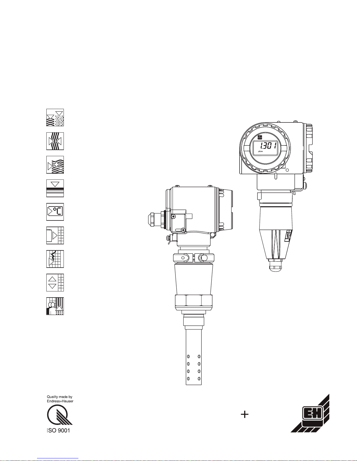
CLM 431 / CLD 431
Conductive
Two-Wire Transmitter
for Conductivity and
Resistance
Operating Instructions
Endress Hauser
The Power of Know How
Page 2

Page 3
Please familiarise yourself with the instrument before
you take any other steps:
Safety
General information
You wish to install and prepare the instrument for startup. The required steps are described in these chapters:
Installation
You wish to operate or reconfigure the instrument. The
operating concept is explained in these chapters:
Operation
Functional description
Interfaces
When you encounter problems or when the instrument
requires maintenance, refer to these chapters for help:
Troubleshooting
Service and maintenance
Accessories
Technical data
Page 4

LM431CE0.CHP
Table of contents
1 General information . . . . . . . . . . . . . . . . . . . . . . . . . . . . . . . . . . . . . . . . . . . . . . . . . . . 2
1.1 Symbols used . . . . . . . . . . . . . . . . . . . . . . . . . . . . . . . . . . . . . . . . . . . . . . . . . . . . . . . . . 2
1.2 Storage and transport . . . . . . . . . . . . . . . . . . . . . . . . . . . . . . . . . . . . . . . . . . . . . . . . . . . 2
1.3 Unpacking . . . . . . . . . . . . . . . . . . . . . . . . . . . . . . . . . . . . . . . . . . . . . . . . . . . . . . . . . . . . 2
1.4 Packaging and disposal . . . . . . . . . . . . . . . . . . . . . . . . . . . . . . . . . . . . . . . . . . . . . . . . . 2
1.5 Productstructure....................................................... 3
2 Safety ............................................................... 5
2.1 Intendeduse.......................................................... 5
2.2 Generalsafetynotes.................................................... 5
2.3 Installation, start-up, operation . . . . . . . . . . . . . . . . . . . . . . . . . . . . . . . . . . . . . . . . . . . . 5
2.4 Monitoringandsafetyfeatures............................................ 6
2.5 Immunity to interference . . . . . . . . . . . . . . . . . . . . . . . . . . . . . . . . . . . . . . . . . . . . . . . . . 6
2.6 Certificate of conformity . . . . . . . . . . . . . . . . . . . . . . . . . . . . . . . . . . . . . . . . . . . . . . . . . 6
2.7 Notes for installation in hazardous areas . . . . . . . . . . . . . . . . . . . . . . . . . . . . . . . . . . . . 6
3 Installation . . . . . . . . . . . . . . . . . . . . . . . . . . . . . . . . . . . . . . . . . . . . . . . . . . . . . . . . . . 7
3.1 Measuring system . . . . . . . . . . . . . . . . . . . . . . . . . . . . . . . . . . . . . . . . . . . . . . . . . . . . . 7
3.2 Dimensions . . . . . . . . . . . . . . . . . . . . . . . . . . . . . . . . . . . . . . . . . . . . . . . . . . . . . . . . . . . 8
3.3 Mounting............................................................ 10
3.4 Connection of conductivity measuring cells . . . . . . . . . . . . . . . . . . . . . . . . . . . . . . . . . 14
3.5 Electrical connection. . . . . . . . . . . . . . . . . . . . . . . . . . . . . . . . . . . . . . . . . . . . . . . . . . . 17
3.6 Connection of MyPro in Ex area . . . . . . . . . . . . . . . . . . . . . . . . . . . . . . . . . . . . . . . . . . 19
4 Operation . . . . . . . . . . . . . . . . . . . . . . . . . . . . . . . . . . . . . . . . . . . . . . . . . . . . . . . . . . . 20
4.1 Start-up ............................................................. 20
4.2 Power-up, factory settings. . . . . . . . . . . . . . . . . . . . . . . . . . . . . . . . . . . . . . . . . . . . . . . 20
4.3 Operating concept / operating elements . . . . . . . . . . . . . . . . . . . . . . . . . . . . . . . . . . . 21
4.4 Display. . . . . . . . . . . . . . . . . . . . . . . . . . . . . . . . . . . . . . . . . . . . . . . . . . . . . . . . . . . . . . 22
4.5 Lockingconcept...................................................... 22
4.6 Operatinglevel1 ..................................................... 23
4.7 Operatinglevel2...................................................... 26
5 Functional description. . . . . . . . . . . . . . . . . . . . . . . . . . . . . . . . . . . . . . . . . . . . . . . . 27
5.1 Main parameters . . . . . . . . . . . . . . . . . . . . . . . . . . . . . . . . . . . . . . . . . . . . . . . . . . . . . . 27
5.2 Basic functions . . . . . . . . . . . . . . . . . . . . . . . . . . . . . . . . . . . . . . . . . . . . . . . . . . . . . . . 29
5.3 Calibration parameters . . . . . . . . . . . . . . . . . . . . . . . . . . . . . . . . . . . . . . . . . . . . . . . . . 31
5.4 Alpha table ...................................................... 32
5.5 Polarisationdetection.................................................. 33
5.6 Diagnosis............................................................ 33
5.7 Service and simulation . . . . . . . . . . . . . . . . . . . . . . . . . . . . . . . . . . . . . . . . . . . . . . . . . 35
5.8 Userinfo............................................................. 36
6 Interfaces . . . . . . . . . . . . . . . . . . . . . . . . . . . . . . . . . . . . . . . . . . . . . . . . . . . . . . . . . . . 37
6.1 HART.............................................................. 37
6.2 PROFIBUS-PA . . . . . . . . . . . . . . . . . . . . . . . . . . . . . . . . . . . . . . . . . . . . . . . . . . . . . . . . 41
7 Troubleshooting . . . . . . . . . . . . . . . . . . . . . . . . . . . . . . . . . . . . . . . . . . . . . . . . . . . . . 42
7.1 Error indication . . . . . . . . . . . . . . . . . . . . . . . . . . . . . . . . . . . . . . . . . . . . . . . . . . . . . . . 42
7.2 Diagnostic codes (error codes) . . . . . . . . . . . . . . . . . . . . . . . . . . . . . . . . . . . . . . . . . . 42
8 Service and maintenance . . . . . . . . . . . . . . . . . . . . . . . . . . . . . . . . . . . . . . . . . . . . . 44
8.1 Cleaning............................................................. 44
8.2 Repairs. . . . . . . . . . . . . . . . . . . . . . . . . . . . . . . . . . . . . . . . . . . . . . . . . . . . . . . . . . . . . . 44
9 Accessories . . . . . . . . . . . . . . . . . . . . . . . . . . . . . . . . . . . . . . . . . . . . . . . . . . . . . . . . . 45
10 Technical data. . . . . . . . . . . . . . . . . . . . . . . . . . . . . . . . . . . . . . . . . . . . . . . . . . . . . . . 46
11 Index............................................................... 49
mypro CLM 431 / CLD 431 conductive Table of contents
Endress+Hauser 1
Page 5

1 General information
1.1 Symbols used
Warning:
This symbol alerts to hazards which
may cause serious injuries as well as
damage to equipment if ignored.
Note:
This symbol indicates important
items of information. Ignoring this
information may result in malfunction.
1.2 Storage and transport
The packaging material used to store or transport the instrument must provide shock protection. Optimal protection is provided by the
original packaging materials.
Conformance with the ambient conditions
(see Technical data) must be assured.
1.3 Unpacking
Verify that the packaging and contents are
undamaged! Inform the post office or freight
carrier of any damage. Damaged merchandise must be retained until the matter has
been settled.
Check that the delivery is complete and
agrees with the shipping documents and your
order (refer to nameplate for type and variant).
The delivery includes:
MyPro CLM 431:
• Measuring transmitter MyPro CLM 431
• Housing fastening elements
• Prepared cable (depending on version)
• Operating instructions BA 202C/07/en
• Certificate of conformity
(depending on version)
MyPro CLD 431:
• Measuring transmitter MyPro CLD 431
with measuring cell CLS 12
• Operating instructions BA 202C/07/en
• Certificate of conformity
(depending on version)
Keep the original packaging materials for
future storage or shipping of the instrument.
If you have any questions, consult your supplier or the Endress+Hauser sales agency in
your area (see back cover of these operating
instructions for addresses).
1.4 Packaging and disposal
Package the assembly properly for reuse at a
later point in time. Optimal protection is
provided by the original packaging materials.
Observe local regulations for disposal.
General information mypro CLM 431 / CLD 431 conductive
2 Endress+Hauser
Page 6
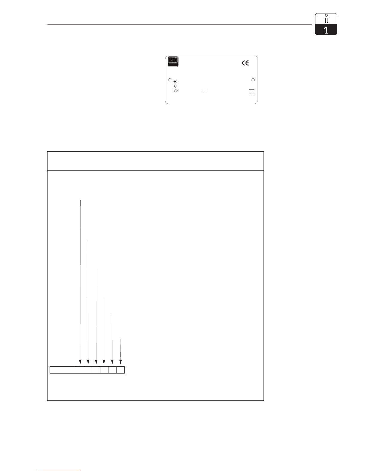
1.5 Product structure
You can identify the instrument variant by the
order code on the nameplate.
4 ... 20mA , HART
s er.-no.
or der code
MYPRO
ENDRESS+HAUSER
U min 12V
U max 30V
Pmax 750mW
xxx xx
-35°C ... 250°C
0 ... 60mS / 0 ... 200 MΩ0 ... 60mS / 0 ... 200 MΩ
CLM431-A3C2ME
Fig. 1.1
Example of
nameplate of CLM 431
LM431CE1.CHP
Certificate type
A Version for non-Ex area
H Cenelec EEx ia/ib IIC T4 (dir. 76/117/EEC; dir. 94/9/EC)
Cable entry for power supply
1 Cable gland Pg 13.5
3 Cable entry M 20 x 1.5
5 Cable entry NPT ½ “
7 Cable entry G ½
8 Cable entry M 12
Electronics, communication, display
A 4 ... 20 mA, HART, without display
B 4 ... 20 mA, HART, liquid crystal display
C PROFIBUS-PA, without display
D PROFIBUS-PA, liquid crystal display
Accessories
1 No accessories
2 For wall and pipe mounting (DN 60)
3 For wall and pipe mounting (DN 30 ... 200)
4 With angle bracket for flange mounting
Preset measuring parameter
C Conductive, conductivity measurement
M Conductive, resistance measurement
Cable, measuring cell connection
A Without cable
C With CYK 71 cable, length 1 m
E With CYK 71 cable, length 2 m
CLM 431-
complete order code
MyPro CLM 431 conductive
mypro CLM 431 / CLD 431 conductive General information
Endress+Hauser 3
Page 7
4 ... 20mA , HART
s er.-no.
or der code
MYPRO
ENDRESS+HAUSER
U min 12V
U max 30V
Pmax 750mW
xxx xx
-35°C ... 160°C
0,04 ...20 S /cm/ 0 ... 25 MµΩ0,04 ...20 S /cm/ 0 ... 25 MµΩ
CL D-A 1D1CA
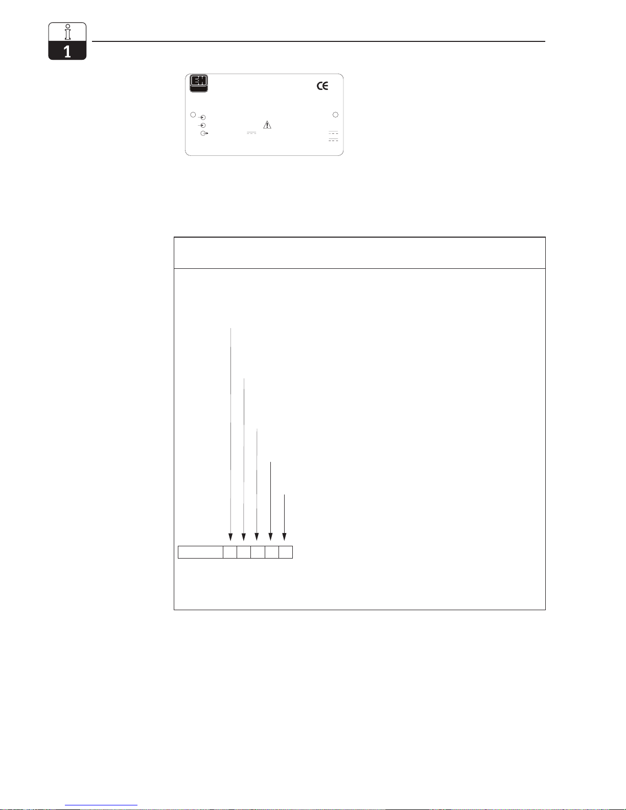
Fig. 1.2
Example of
nameplate of CLD 431
Certificate type
A Version for non-Ex area
H Cenelec EEx ia/ib IIC T4 (dir. 76/117/EEC; dir. 94/9/EC)
Cable entry for power supply
1 Cable gland Pg 13.5
3 Cable entry M 20 x 1.5
5 Cable entry NPT ½ “
7 Cable entry G ½
8 Cable entry M 12
Electronics, communication, display
A 4 ... 20 mA, HART, without display
B 4 ... 20 mA, HART, liquid crystal display
C PROFIBUS- PA, without display
D PROFIBUS-PA, liquid crystal display
Accessories
1 No accessories
Measuring cell, process connection and material
CA CLS 12, 0.04 ... 20 µS, G1, stainless steel1.4571
CB CLS 12, 0.1 ...200 µS, G1, stainless steel 1.4571
CLD 431-
complete order code
MyPro CLD 431 conductive
General information mypro CLM 431 / CLD 431 conductive
4 Endress+Hauser
Page 8
2 Safety
2.1 Intended use
The MyPro CLM 431 / CLD 431 is a fieldtested and reliable measuring transmitter
for determining the conductivity and specific
resistance of liquid media.
In particular, the MyPro CLM 431 / CLD 431
is suitable for use in the following areas of
application:
• Chemical industry
• Pharmaceutical industry
• Foodstuffs industry
• Drinking water treatment
• Condensate processing
• Municipal sewage treatment plants
• Industrial effluent treatment
The instrument design permits operation in
explosive atmospheres (zone 1 according to
ElexV).
2.2 General safety notes
This device has been manufactured for safe
operation according to the state of the art in
engineering and conforms to the applicable
regulations and European standards (see
Technical data). It has been designed
according to EN 61010-1 and has left the
manufacturer’s works in perfect condition.
However, if used improperly or for purposes
other than the intended purpose, it may be
dangerous, e.g. due to incorrect connection.
Warning:
• Operating this instrument in any
way other than as described in
these instructions may compromise the safety and function of the
measuring system and is therefore impermissible.
• The notes and warnings in these
installation and operating instructions must be strictly adhered to!
2.3 Installation, start-up, operation
Warning:
• This device may only be installed,
connected electrically, commissioned, operated and serviced by
properly trained personnel authorized by the system operator.
• The personnel must be familiar
with these operating instructions
and must adhere to the instructions
described therein.
• Before connecting the instrument
to the mains, make sure that the
mains voltage matches the voltage
rating on the nameplate.
• When connecting an instrument in
an explosive atmosphere, adherence to the applicable regulations
is mandatory (see chapter 2.7).
• Check that all connections have
been properly made before powering up the system!
• The instrument housing must be
grounded before start-up!
• Damaged equipment that may be
dangerous must not be operated
and should be clearly identified as
being defective.
• Any troubleshooting of the measur-
ing system is to be performed
exclusively by authorized, trained
personnel.
• If faults cannot be remedied, the
instrument must be removed from
service and secured to prevent
accidental start-up.
• Repair work must be carried out
directly by the manufacturer or
by the Endress+Hauser Service
Organization.
LM431CE2.CHP
mypro CLM 431 / CLD 431 conductive Safety
Endress+Hauser 5
Page 9
2.4 Monitoring and safety features
Monitoring features
If a problem ever occurs, an alarm symbol
flashes on the display, and a defined error
current (22 mA +/– 0.5 mA) is output via the
current interface.
Safety features
This instrument is protected against external
influences and damage by the following
design measures:
• Massive metal housing
• UV-resistant front panel
• Housing protection type IP 65
2.5 Immunity to interference
This instrument has been tested according to
the applicable European standards for industrial applications with regard to electromagnetic compatibility and has been protected
against electromagnetic interference (see
Technical data in chapter 10).
Warning:
• The specified immunity to inter-
ference only applies for devices
connected as outlined in these
operating instructions.
2.6 Certificate of conformity
The MyPro CLM / CLD 431 transmitter has
been developed and manufactured in
accordance with currently valid European
standards and directives and is suitable for
use in hazardous areas.
Compliance with the harmonised European
standards for the use of the equipment in
hazardous areas is confirmed by this certificate of conformity.
Note:
For the CLM 431-G/H and
CLD 431-H versions an EC
conformity certificate is supplied.
For the -H versions additional safety
instructions (XA 173C/07/en) are
supplied.
2.7 Notes for installation in hazardous areas
The MyPro CLM 431 / CLD 431 transmitter
has been manufactured and tested in
accordance with the harmonised European
regulations (CENELEC) for »electric equipment for hazardous areas«. The equipment
complies with the basic requirements of the
76/117/EEC and directive and is suitable for
use in hazardous areas.
Warning:
• The applicable national regula-
tions are to be observed for installation and operation.
• All lines conducting signals are to
be shielded according to VDE
0165 and to be routed separately
from other control lines.
Note:
For helpful information on the installation and operation of electric
equipment in hazardous areas,
please refer to the Endress+Hauser
fundamental information brochure
GI 003/11/d »Explosionsschutz von
elektrischen Betriebsmitteln und
Anlagen« (»Explosion protection of
electric equipment and systems«).
This brochure can be ordered from
the Endress+Hauser sales offices.
Safety mypro CLM 431 / CLD 431 conductive
6 Endress+Hauser
Page 10
3 Installation
3.1 Measuring system
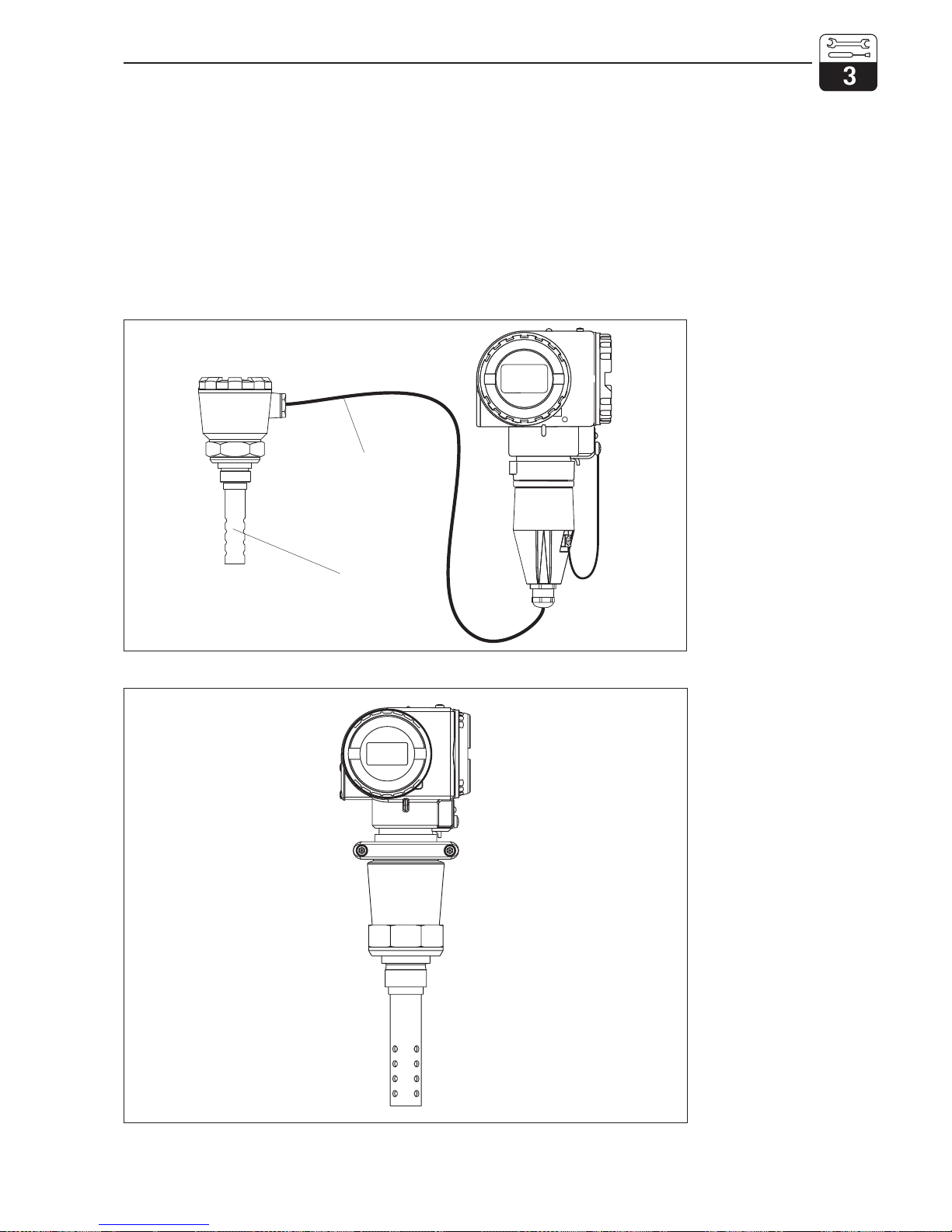
The complete measuring system comprises:
• the MyPro CLM 431 transmitter
• a conductive two-electrode
measuring cell with an integrated
temperature sensor, e.g. CLS 12
• a measuring cable, e.g. CYK 71
• or the compact unit MyPro CLD 431 with
conductivity measuring cell CLS 12
CLS 12
conductive conductivity
measuring cell
with integrated temperature
sensor
Measuring cable
CYK 71
Measuring transmitter
MyPro CLM 431
LM431SYS.CDR
Fig. 3.1
Complete measuring
system consisting of
MyPro CLM 431 with
measuring cable CYK 71
and conductivity
measuring cell
CLS 12
Measuring transmitter
MyPro CLD 431
LM431SY2.CDR
Fig. 3.2
Compact unit
MyPro CLD 431
with integrated
conductivity measuring
cell CLS 12
LM431CE3.CHP
mypro CLM 431 / CLD 431 conductive Installation
Endress+Hauser 7
Page 11
3.2 Dimensions
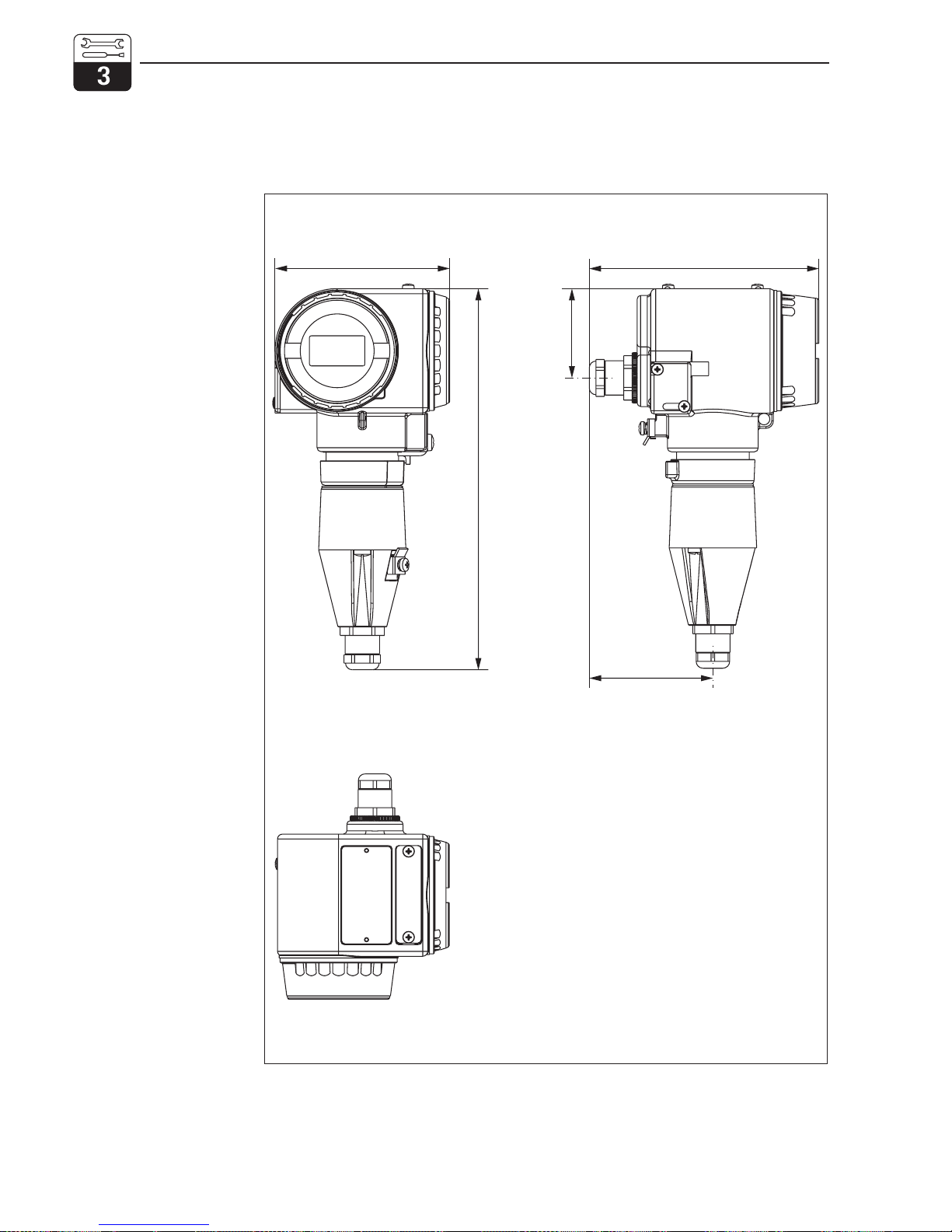
3.2.1 MyPro CLM 431 conductive
104
137
53
74
227
MASSCLM.CDR
Fig. 3.3
Dimensions of
MyPro CLM 431
Installation mypro CLM 431 / CLD 431 conductive
8 Endress+Hauser
Page 12
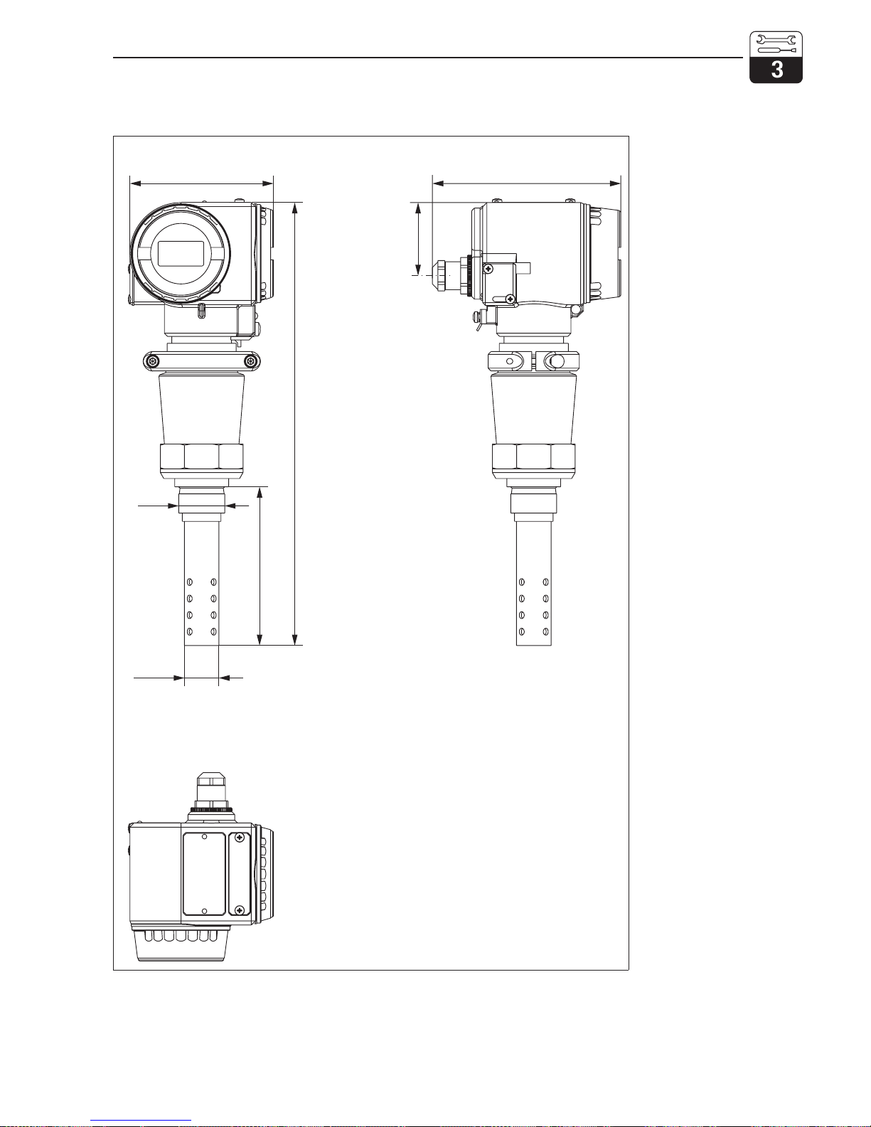
3.2.2 MyPro CLD 431 conductive
MASSCLD.CDR
104 137
321
115
∅ 25
53
Fig. 3.4
Dimensions of
MyPro CLD 431
with CLS 12
G1
LM431CE3.CHP
mypro CLM 431 / CLD 431 conductive Installation
Endress+Hauser 9
Page 13
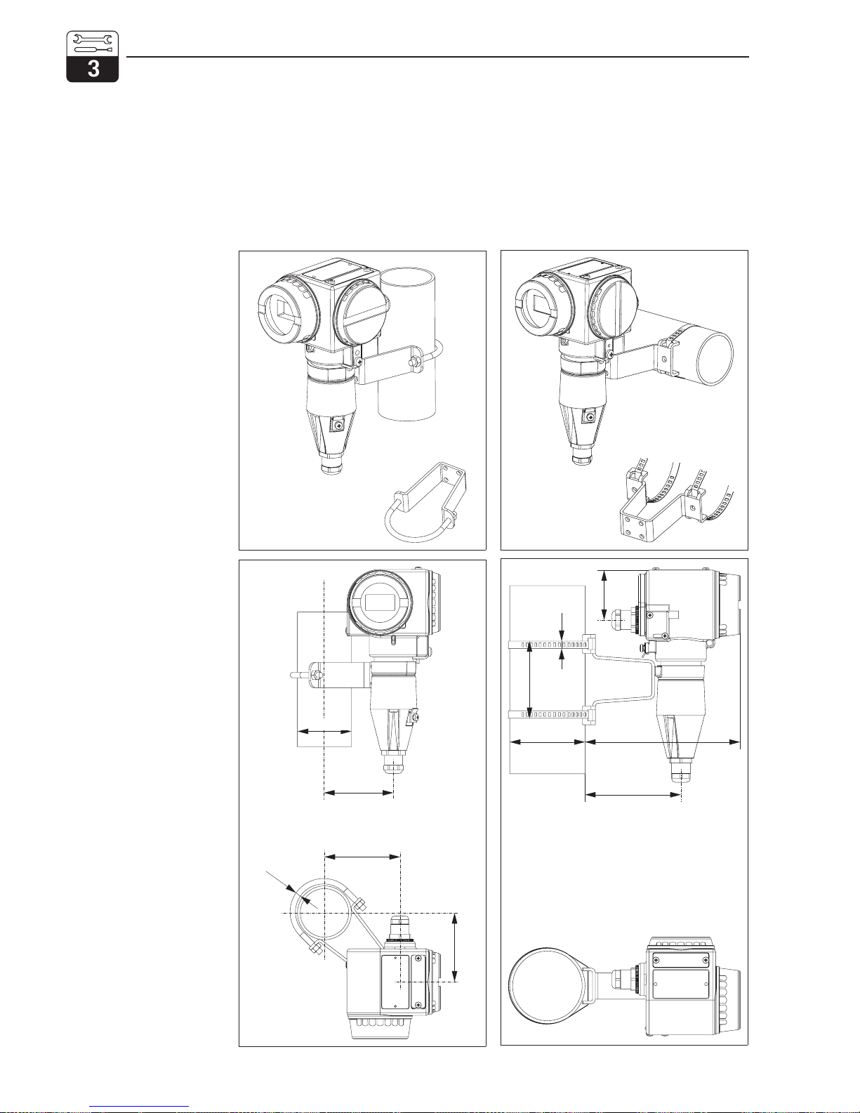
3.3 Mounting
3.3.1 MyPro CLM 431 conductive
The measuring transmitter MyPro CLM 431
can be installed on a wall or pipe using the
holder (depending on version) supplied with
the instrument.
The holder is attached to the MyPro housing
with two screws. The housing can be rotated
90° thanks to four boreholes.
MOUNT3D2.CDR
MOUNT2D2.CDR
82
8
53
∅ 30 ... 200
165
102
MOUNT3D1.CDR
Fig. 3.5
Left:
Pipe mounting DN 60,
with mounting bracket
Right:
Pipe mounting
DN 30 ... 200,
with mounting bracket
(horizontal attachment)
MOUNT2D1.CDR
∅ 60.3
77
84
∅ 6
77
Fig. 3.6
Left:
Pipe mounting DN 60,
with mounting bracket
Right:
Pipe mounting
DN 30 ... 200,
with mounting bracket
(vertical attachment)
Installation mypro CLM 431 / CLD 431 conductive
10 Endress+Hauser
Page 14
MOUNT3D3.CDR MOUNT3D4.CDR
69
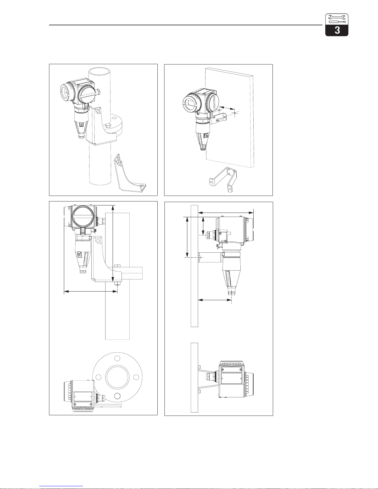
Fig. 3.7
Left:
Flange mounting with
angle bracket
Right:
Wall mounting with
mounting bracket
MOUNT2D3.CDR
177
254
MOUNT2D4.CDR
97
118
160
53
Fig. 3.8
Left:
Flange mounting with
angle bracket
Right:
Wall mounting with
mounting bracket
LM431CE3.CHP
mypro CLM 431 / CLD 431 conductive Installation
Endress+Hauser 11
Page 15
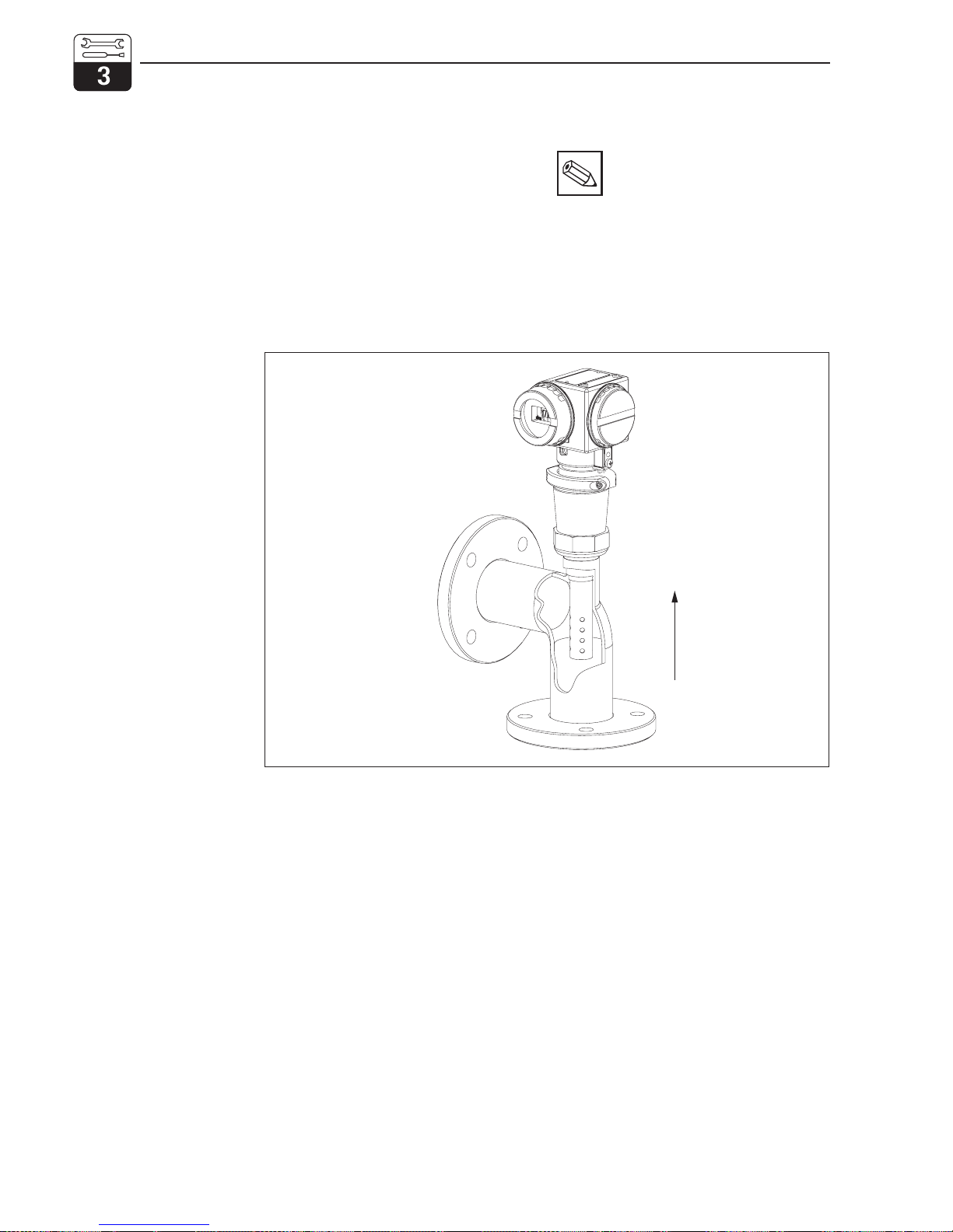
3.3.2 MyPro CLD 431 conductive
The compact version can be installed in a
pipe with medium flow. The distance of the
measuring cell from the inside pipe wall
does not influence the accuracy of the
measurement.
Note:
• The torque to fasten the thread
must not exceed 25 Nm.
• Observe the temperature limits
when installing the compact
version (see Technical data,
fig. 10.1).
MONTAGE6.CDR
flow direction
Fig. 3.9
Pipe mounting of
MyPro CLD 431
Installation mypro CLM 431 / CLD 431 conductive
12 Endress+Hauser
Page 16
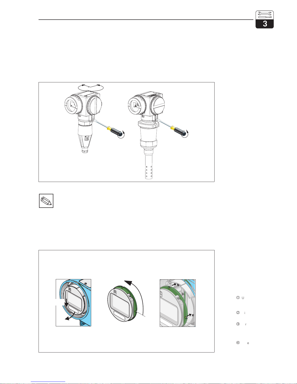
3.3.3 Instrument orientation
Housing orientation
Following horizontal or vertical attachment to
a wall or pipe, the orientation of the housing
can be changed to provide optimal
accessibility.
Note:
Pay attention to the keypad position
during installation. The keys should
be easily accessible.
Display rotation
The display can be rotated to permit perfect
viewing in different mounting positions. It can
be rotated in four 90° steps.
Refer to the figure below for the procedure to
follow.
270°
AUSRICHT.CDR
Fig. 3.10
Housing orientation
Left:
MyPro CLM 431
Right:
MyPro CLD 431
4 x 90°
press
EINBAU.CDR
Fig. 3.11
Removal and installation
of display
Unscrew the lid over
the display. Push the tab
towards the outside.
Tilt the display
forward and remove.
Turn the removed
display in 90° steps.
Reinstall in the desired
orientation.
To reinstall, latch the
display back into the
guide.
LM431CE3.CHP
mypro CLM 431 / CLD 431 conductive Installation
Endress+Hauser 13
Page 17
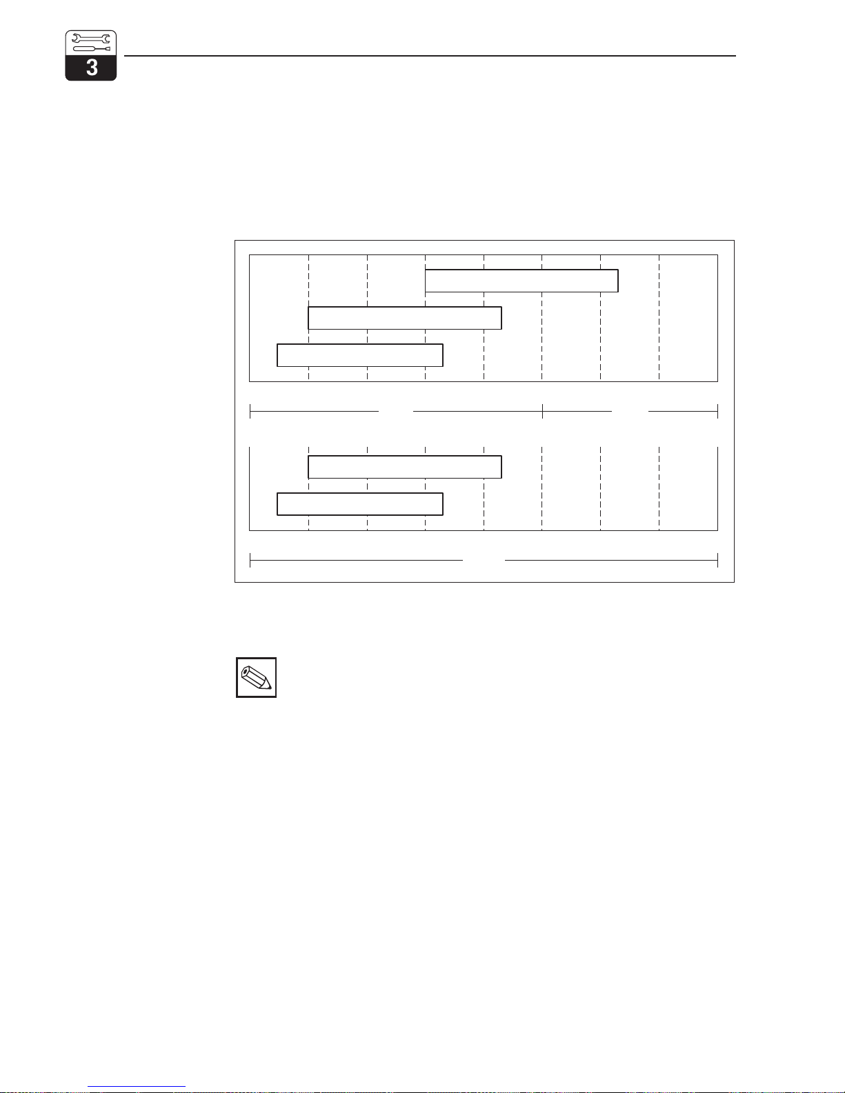
3.4 Connection of conductivity measuring cells
3.4.1 Suitable measuring cells
The following conductive conductivity measuring cells can be used for the measuring transmitter MyPro CLM 431:
Note:
The measuring range depends
on the application range of the
measuring cells used.
3.4.2 Measuring cable connection
Conductivity measuring cells are connected
by means of a special preassembled,
shielded, multi-core measuring cable, type
CYK 71. Should an extension of the measuring cable be necessary, use junction box VS
in conjunction with extension cable CYK 71.
10
0.01
0.0010.01
0.1
0.1
1
1
10
10
100
100
1 100 1000
k
=1CLS 21
k
= 0.1
CLS 12 / 13 / 15 / 19
k
= 0.1
CLS 12 / 13 / 15 / 19
k
= 0.01CLS 12 / 13 / 15 / 19
k
= 0.01CLS 12 / 13 / 15 / 19
µS/cm mS/cm
M·cmΩ
TI172E02.CDR
Fig. 3.12
Overview of suitable
measuring cells with
measuring ranges
Installation mypro CLM 431 / CLD 431 conductive
14 Endress+Hauser
Page 18
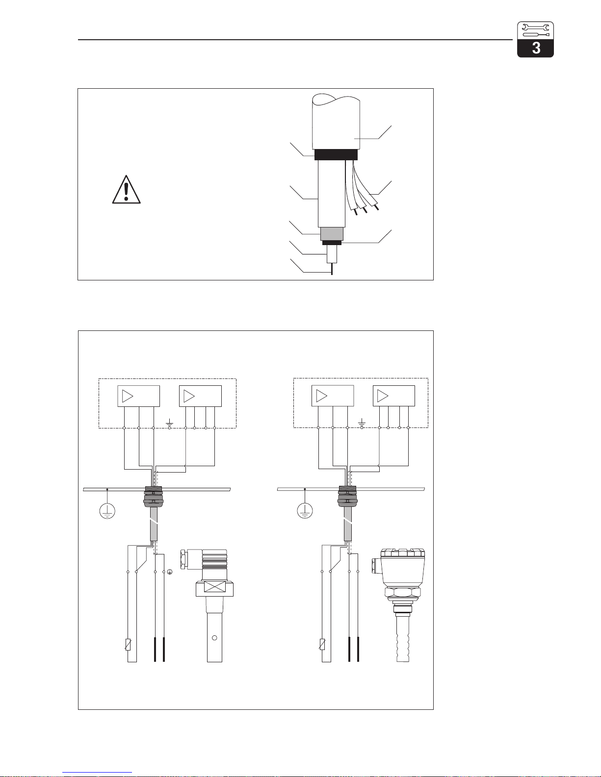
Construction and preparation of CYK 71 cable with examples for connection
13
13
12
12
11
11
14
14
15
15
16
16
17
17
ϑ
ϑ
Cd /MΩ
Cd /MΩ
ϑ
ϑ
bk
bk
gn wt ye
31 2
34 21
gn wt ye
gn wt ye
gn wt ye
LM431C2E.CDR
Fig. 3.14
Connection examples
Left:
Connection of measuring
cell CLS 19 with CYK 71
Right:
Connection of measuring
cell CLS 12 with CYK 71
7
6
3
8
5
4
2
1
Warning:
Semiconductor layer must
be removed down to inner
screen for connection!
LM431K71.CDR
Fig. 3.13
Construction / preparation
of special measuring
cable CYK 71
1 Inner conductor
(measuring signal)
2 Inner insulation
3 Black semiconductor
layer
4 Inner screen
(measuring signal)
5 2nd insulation
6 Auxiliary cores for
Pt 100 (gn/wt/ye)
7 Outer insulation
8 Outer screen
LM431CE3.CHP
mypro CLM 431 / CLD 431 conductive Installation
Endress+Hauser 15
Page 19
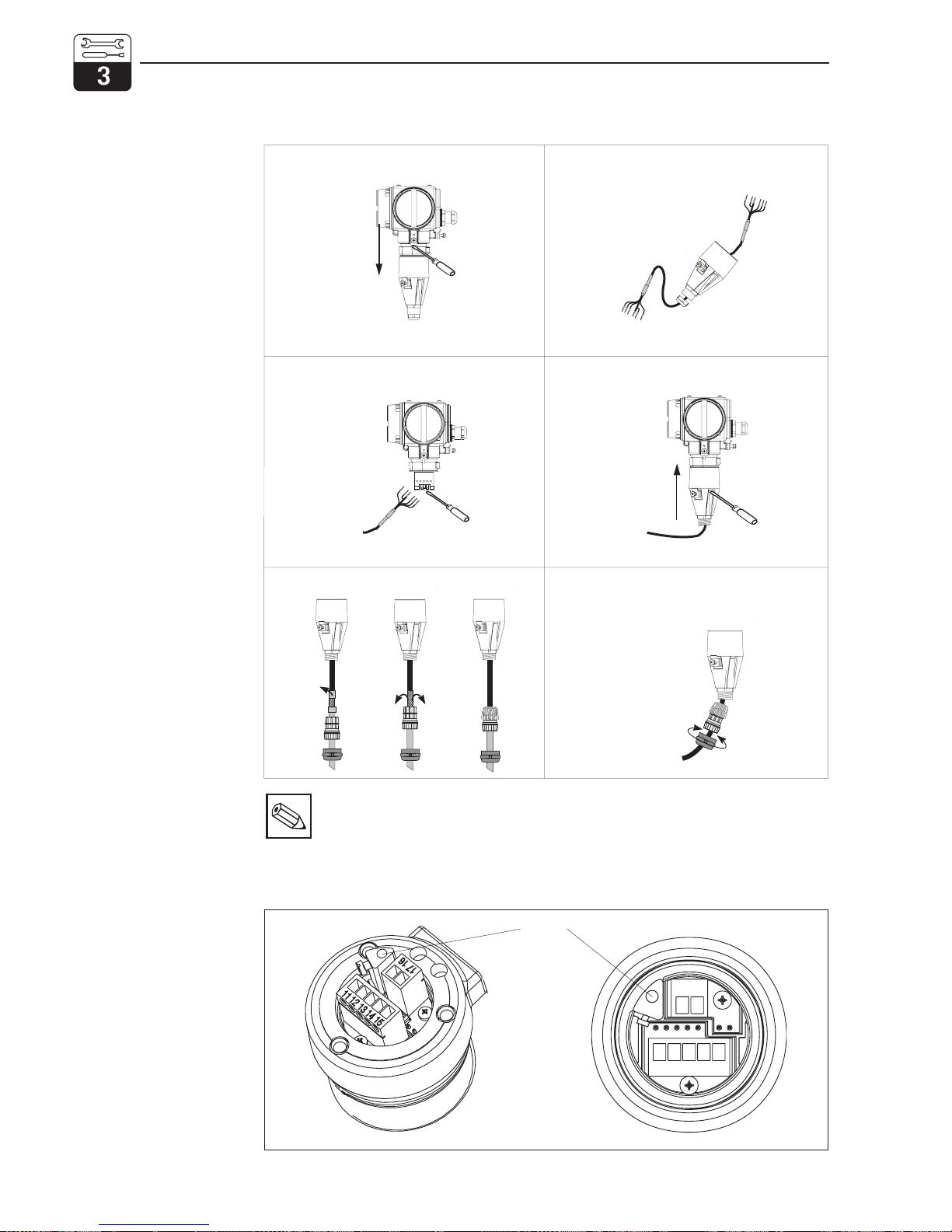
Instructions for measuring cable connection to CLM 431
Note:
The screen can also be connected
to the screen terminal on the
terminal block.
Loosen fastening screws and pull off
connection hood.
Loosen connection hood Pg cable gland and
thread cable through.
Connect cable ends accordingto terminal
assignment diagram (figure 3.14).
Replace connection hood and tighten
fastening screws.
ANSCHL2.CDR
Connect the screen following sequence a to c.
ab c
Pull the cable through until the Pg cable gland can
grasp the cable insulation.Tighten the Pg cable
gland.
Fig. 3.15
Measuring cable
connection
1514131211
17
16
ANSCHL.CDR
Screen
Fig. 3.16 Terminal block
Installation mypro CLM 431 / CLD 431 conductive
16 Endress+Hauser
Page 20
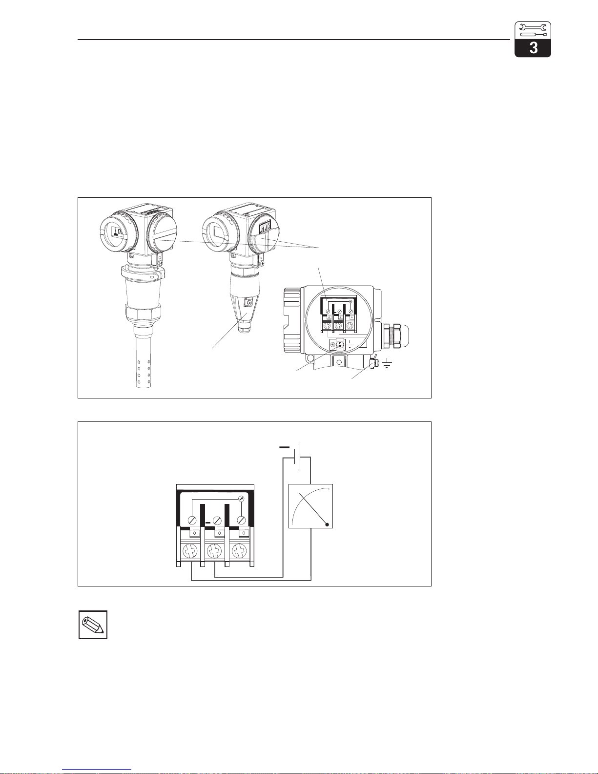
3.5 Electrical connection
The measuring transmitter MyPro CLM 431 /
CLD 431 has separate connection compartments for the power supply and measuring
cell connections.
The terminals for the two-wire line are located
under the screwed cover on the right side of
the instrument.
Proceed as described below to connect the
MyPro CLM 431 / CLD 431:
• Connect the MyPro CLM 431 / CLD 431
transmitter to a 12 ... 30 V power source
• Ground the instrument via the outer
ground terminal.
• Ground the two-wire line screen via the
ground terminal in the connection
compartment.
Note:
• Keep the screen ground line as
short as possible. Connect the
screen directly to the ground
terminal. This also applies to
connection of junction box VS.
• If the instrument is mounted on a
post, ground the post to increase
immunity to interference. Running
the cable in the post will improve
interference suppression.
• Immunity to interference is only
guaranteed when the instrument is
grounded via the shielded twowire line.
4...20 mA
Test
1
3
2
+
0000
Power supply
connection compartment
Measuring cell
connection
compartment
Ground terminal for
cable screen
Ground terminal for
instrument
LM431AN1.CDR
Fig. 3.17
Electrical connection
compartment
4...20 mA
Tes t
1
3
2
+
+
0000
LM431AN2.CDR
Supply voltage
12 ... 30 V DC
Signal output
4 ... 20 mA current
Fig. 3.18 Electrical connection
LM431CE3.CHP
mypro CLM 431 / CLD 431 conductive Installation
Endress+Hauser 17
Page 21
Resistance
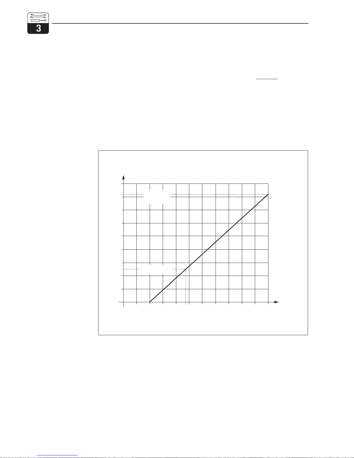
The required minimum supply voltage of the
transmitter depends on the resistance of the
evaluation instrument connected.
The following diagram shows the required
supply voltage when connecting the HART
interface and the maximum admissible
resistance in the transmitter circuit.
The maximum admissible resistance R
max
is
derived from the following formula:
with UV= supply voltage of the
transmitter circuit (DC)
UM= terminal voltage of the
transmitter (12 V DC)
I
max
= maximum current of the
transmitter (22 mA)
R
UU
VM
ax
ma x
m
I
=
−
30
U [V DC]
V
U [V DC
]
V
20
17,5
12
10
100
200
820
750
250
300
400
500
600
700
800
900
R [ ]ΩR [ ]Ω
supply voltage
resistance with
HART interface
resistance
maximum
admissible
resistance
BUERDE.CDR
Fig. 3.19
Admissible resistance in
the transmitter circuit
Installation mypro CLM 431 / CLD 431 conductive
18 Endress+Hauser
Page 22
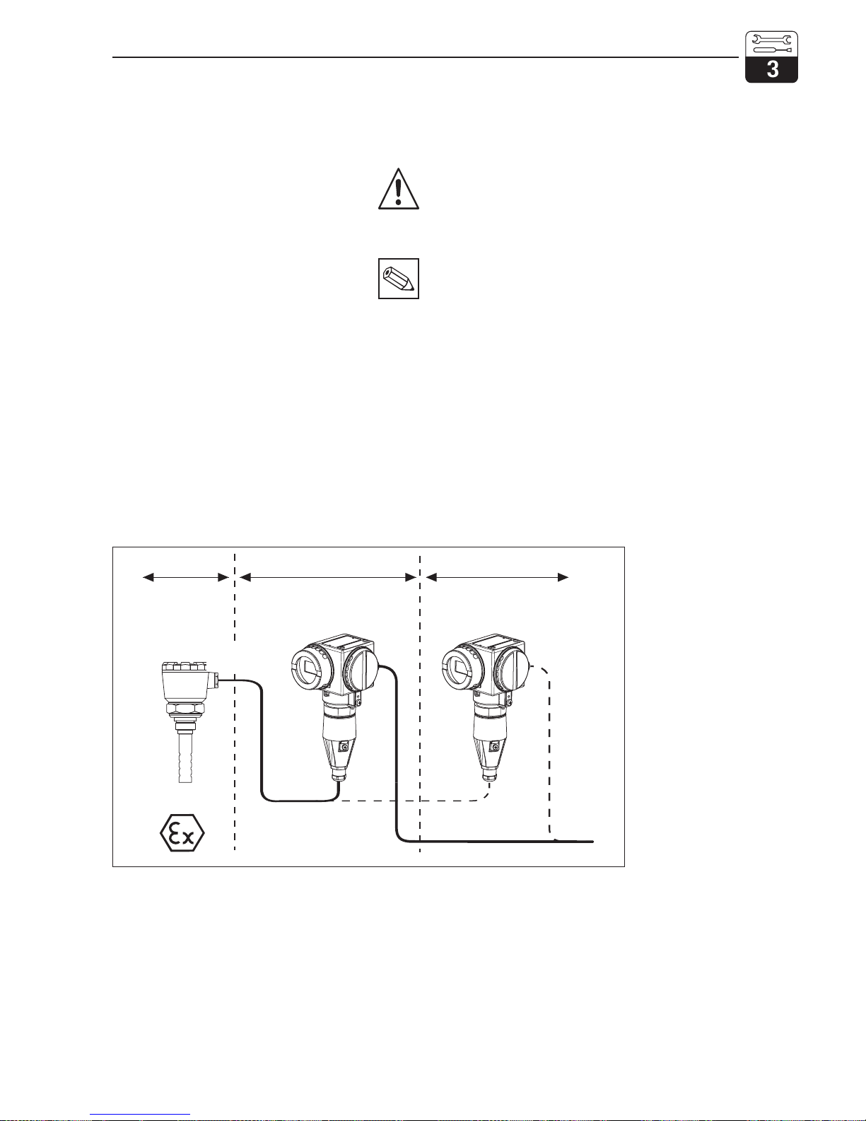
3.6 Connection of MyPro in Ex area
Connection of MyPro CLM 431-G
The CLM 431-G instrument approved
according to directive 76/117/EEC may be
installed in Ex area 1 or 2. Observing the
European directive IEC 60079-14, the
intrinsically safe sensor circuit (ia) may also
pass through zone 0.
Connection of MyPro CLM 431-H
The CLM 431-H instrument approved
according to directive 76/117/EEC may be
installed in Ex area 1 or 2. Observing the
European directive IEC 60079-14, the
intrinsically safe sensor circuit (ia) may also
pass through zone 0.
Connection of MyPro CLD 431-H
The CLD 431-H instrument approved
according to directive 76/117/EEC may be
installed in Ex area 1 or 2.
Only devices with an intrinsically safe output
circuit may be connected to Ex versions of
the measuring transmitter.
Warning:
The display and connection
compartment covers must remain
closed during operation.
Note:
Also observe the safety notes for
instrument installation in explosive
atmospheres in chapter 2.7 of these
operating instructions.
Ex zone 1
Control room (non-Ex)
ia circuit
(sensor)
ib circuit
(signal output / power supply)
LM431-EX.CDR
Ex zone 0 / 1
Fig. 3.20
Measuring transmitter and
measuring cell in Ex area
LM431CE3.CHP
mypro CLM 431 / CLD 431 conductive Installation
Endress+Hauser 19
Page 23
4 Operation
4.1 Start-up
Note:
• Familiarise yourself with the opera-
tion of the measuring instrument
before switching it on for the first
time!
• Before power-up, check that all
connections have been properly
made!
• Make sure that the measuring cell
is immersed in the medium to be
measured or a calibration solution.
This ensures that a plausible value
will be displayed.
4.2 Power-up, factory settings
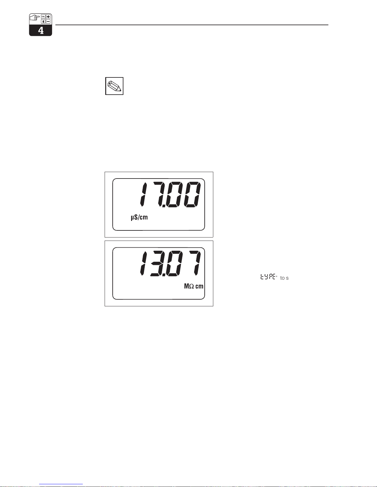
The MyPro CLM 431 / CLD 431 does not have
an “ON switch”. When power is applied, the
instrument performs a self-test and then starts
up in the measuring mode using the parameters last set. The display should be similar to
one of the figures below. Of course, the dis-
play value may be different. µS/cm or mS/cm
on the display stands for conductivity, MΩ cm
or kΩ cm stands for resistance measurement.
If the display indicates a plausible value, the
cell constant can be entered, allowing the
transmitter to display the measured values
correctly. The instrument is then ready for
measurement.
Use the function “
type
” to switch between
the operating modes conductivity and
resistance, see chapter 5.1.
Refer to chapters 4.6.4 and 5 for notes on
calibration.
Fig. 4.1 Conductivity measurement
Fig. 4.2 Resistance measurement
Operation mypro CLM 431 / CLD 431 conductive
20 Endress+Hauser
Page 24
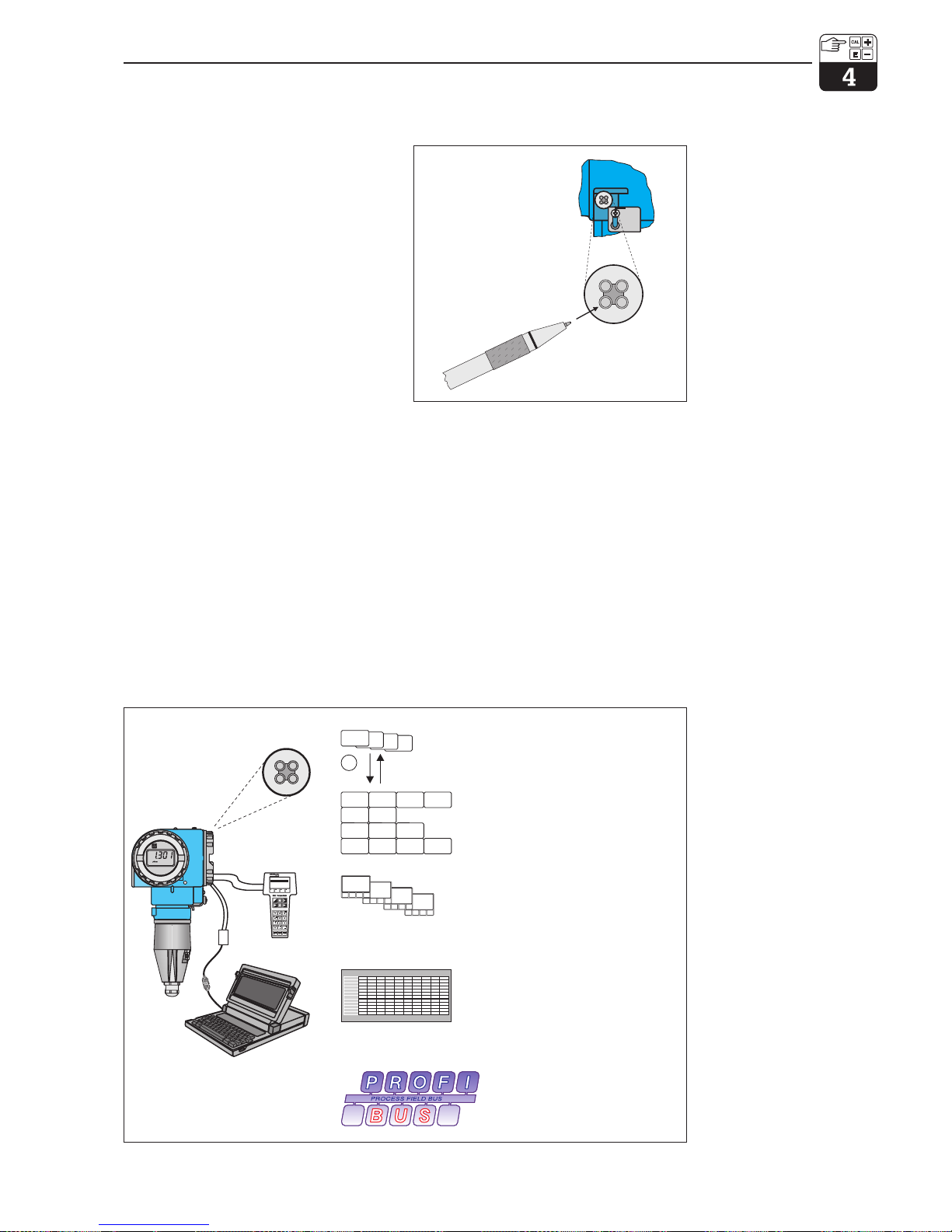
4.3 Operating concept / operating elements
The intelligent MyPro CLM 431 / CLD 431
transmitter can be operated in the field with 4
keys or via the HART interface (hand-held
terminal or Commuwin II) or via Profibus PA.
The 4 keys are located on the side of the
instrument under a hinged cover and can be
actuated with a pointed object, such as, for
example, the tip of a ball point pen.
The printing on the adhesive label above the
key pad shows the key arrangement .
The following functions can be accessed in
the field via the keypad:
Operating level 1
• Verification of active settings (secondary
parameter)
• Error diagnosis (diagnostic parameters)
• Current interface settings (instrument
parameters)
• Calibration
Operating level 2
This level comprises all other settings, e.g.
switching from conductivity to resistance
measurement.
Key functions at operating level 1:
+ Select secondary parameter /
set values
– Select diagnostic parameters /
set values
F Instrument configuration
C Sensor calibration
HARTHandterminal
1 Offline
3 Transfer
4 Frequenzgerät
5Extras
2 Online➔
I
O
–
+
C
F
F
>3s
Keypad on
instrument
Hand-held
HART terminal
Commuwin II via HART
Commuwin II
via PROFIBUS PA
LM431OP.CDR
Operating level 1
• Daily workand diagnosis
Operating level 2
• Configuration and diagnosis
• Plain-textmenu guidance
• Clearoverall view in the form of
a matrix
• Graphicaluser interface
• Dataentry/recorder function
• Upload/download archiving
• Off-lineparameter setting
• Extendedcommunication functions
• Access toall instrument parameters
• Permitsinterconnectionof units from
different manufacturers
Fig. 4.4
Operation of MyPro
CLM 431 / CLD 431 is
possible via:
– keys on instrument
– hand-held HART terminal
– Commuwin II via HART
– Commuwin II via
PROFIBUS-PA.
–
+
C
E
–
+
C
F
KA010Y52.CDR
Key actuation, e.g.
with the tip of a
ball point pen
Fig. 4.3 Keypad
LM431CE4.CHP
mypro CLM 431 / CLD 431 conductive Operation
Endress+Hauser 21
Page 25
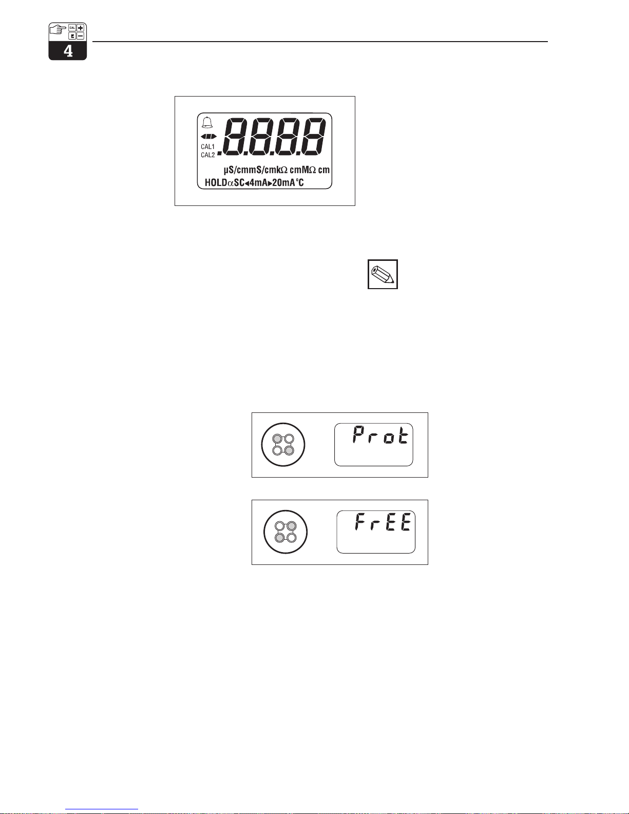
4.4 Display
The figure on the left shows the complete
MyPro display.
Various symbols are displayed depending on
the instrument settings.
4.5 Locking concept
Access to instrument operation and write protection for field operation can be disabled via
the keypad or the communication interface.
The keypad has priority over the interface, i.e.
an instrument which has been locked in the
field cannot be unlocked via the communication interface.
Note:
• The previous locking status is
retained after a power failure or
reset.
• The factory setting (status at time
of delivery) is ‘unlocked’.
Unlocking / locking via interface and field operation (operating level 2):
See chapters 4.7 and 5.
%
LM431DIS.CDR
–
+
C
F
–
+
C
F
Instrument is locked
Parameters can only be
read in the field and via
communication; „Prot“
(= write-protected) is displayed when operation is
attempted
Instrument is
unlocked
Press „–“ and
„C“ once at the
same time
Press „+“and
„F“ once at the
same time
Operation mypro CLM 431 / CLD 431 conductive
22 Endress+Hauser
Page 26
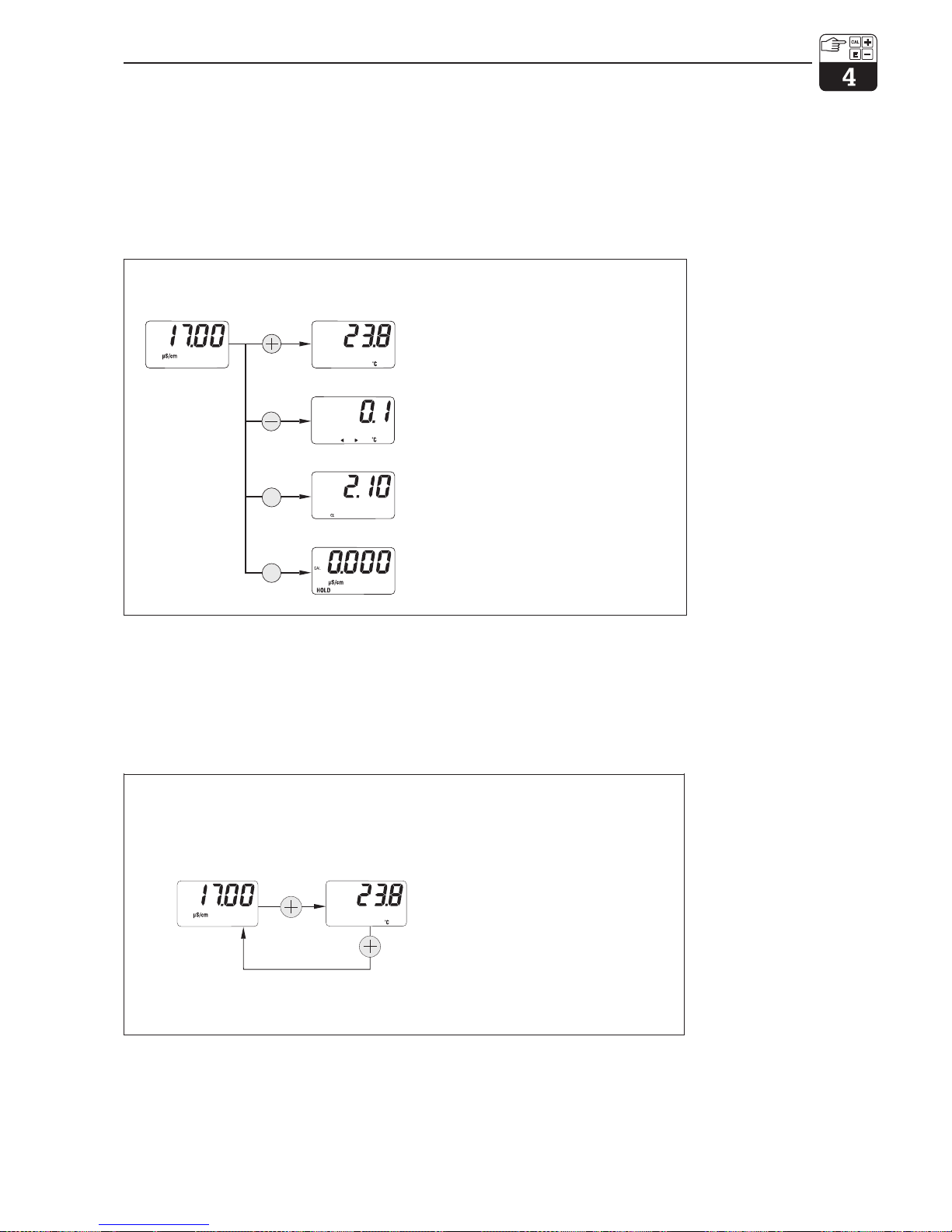
4.6 Operating level 1
Display mode selection
The display normally shows the currently
measured value. The four operating keys are
used to access the various display modes
explained on the pages to follow.
4.6.1 Secondary parameter menu (temperature)
The secondary parameter menu is used
to display parameters that influence the
measured value (temperature).
If no other key is pressed for 30 s, the
instrument automatically switches back
to the measured value display.
F
C
Normal meas.
mode
Key Display
Description
Temperature menu
Call up with „+” and continue
See chapter 4.6.1
Diagnostic parameter menu
Call up with „–“ and continue
See chapter 4.6.2
Parameter setting menu
Call up with „F” and continue
See chapter 4.6.3
Calibration menu
Request calibration with „C”, continue
See chapters 4.6.4 and 4.7
ANZ1.CDR
Normal meas.
mode
Key Display
Description
Temperature
Current temperature in °C
at the temperature sensor
ANZ2.CDR
LM431CE4.CHP
mypro CLM 431 / CLD 431 conductive Operation
Endress+Hauser 23
Page 27
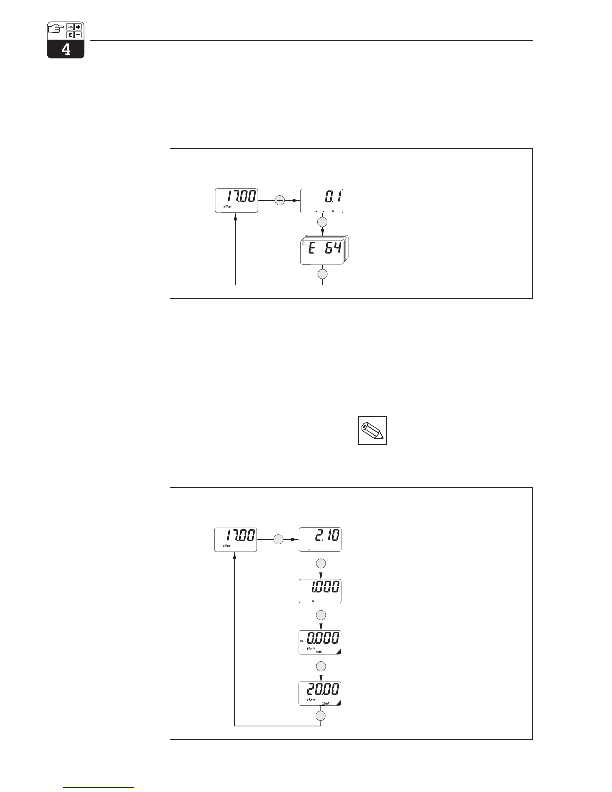
4.6.2 Diagnostic parameter menu
The diagnostic parameters show the current
temperature offset (from temperature calibration) and the diagnostic codes (error messages) that are active, beginning with the
highest priority (Prio_1). If no other key is
pressed for 30 s, the instrument automatically
switches back to the measured value display.
4.6.3 Parameter settings
This function can be used to display and set
the values that are essential for start-up.
These are:
• Temperature coefficient (α value)
• Cell constant
• Meas. value for 4 mA current output
• Meas. value for 20 mA current output
The value being edited flashes. When the
desired value has been entered, it is
accepted with „F”, and the system advances
to the next parameter.
Adjustment ranges
Temperature coeff. α:0.00 to 10.00 %/K
Cell constant C: 0.0025 to 99.99 cm
–1
Minimum distance 20 µS/cm / 200 µS/cm
4/20 mA value: 2 mS/cm / 20 mS/cm
(dep. on meas. range)
Note:
A minimum distance between the 4
and 20 mA values is required (see
chapter 10) ➞ an error is signalled if
this condition is not fulfilled.
Diagnostic codes (up to 5 messages)
Continue with „–“
Display of „E–––“ indicates ‘no error’
Temperature offset
For checking of and information on temperature calibration (see chapter 4.6.4 )
ANZ3.CDR
Normal meas.
mode
Key Display
Description
F
F
F
F
F
Temperature coefficient
Display of current α value
Edit with „+“or„–“ (value flashes)
Cell constant
Display of current cell constant
Edit with „+“or„–“ (value flashes).
Measured value at 4 mA
Display of current value at 4 mA
Edit with „+“or„–“ (value flashes)
Measured value at 20 mA
Display of current value at 20 mA
Edit with „+“or„–“ (value flashes)
ANZ4.CDR
Normal meas.
mode
Key Display
Description
Operation mypro CLM 431 / CLD 431 conductive
24 Endress+Hauser
Page 28
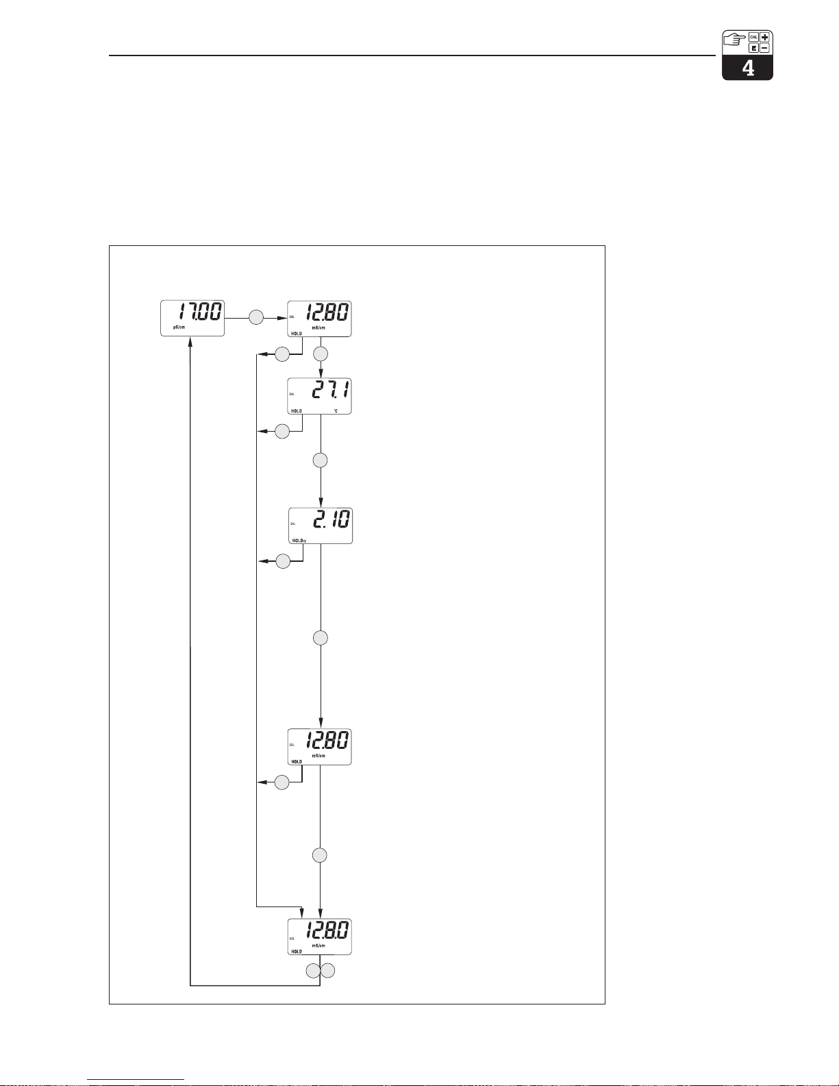
4.6.4 Calibration
The calibration menu of the MyPro CLM 431 /
CLD 431 is used for temperature and conductivity calibration. The conductivity calibration,
i.e. the determination of the cell constant, can
be performed with or without automatic temperature compensation. The temperature
coefficient and the uncompensated conducti-
vity of the calibration solutions as a function of
temperature are documented.
The calibration menu can be exited anytime
by pressing the „F“ key; an error message
(calibration aborted) will be displayed.
C
C
C
C
F
F
F
C
F
C
F
Beginning of calibration
Place measuring cell in calibration solution.
Continue with „C“, abort with „F“
Temperature calibration
The measured value determined by the
MyPro is displayed. The value can be edited
directly with „+“ and „–“ for adjustment to the
correct value. The MyPro automatically determines the temperature offset (see chapter
4.6.2 „Diagnostic parameter menu“)
Temperature coeff. of calibration solution
If the temperature of the calibration solution
differs from the reference temperature (instrument), you must choose one of the following
alternatives to proceed:
1.) Calibration with uncompensated
conductivity, i.e. α =0.
Enter the uncomp. conductivity of the
calibration solution at the current
temperature.
2.) Calibration with automatic
temperature compensation,
i.e. enter the α value of the calibration
solution at the current temperature.
Conductivity calibration
Entry of conductivity of calibration solution
with „+“and„–“
Depending on preceding step:
For 1.) Determine uncomp. conductivity of
calibration solution at current
temperature and enter.
For 2.) Enter compensated value of
calibration solution at reference
temperature.
Cell constant editing may be performed
by entering the cell constant from the
nameplate or from the quality certificate of
End of calibration
Continue measurement with „C“or„F“; the
current output is re-enabled.
ANZ6.CDR
Normal meas.
mode
Key Display Description
LM431CE4.CHP
mypro CLM 431 / CLD 431 conductive Operation
Endress+Hauser 25
Page 29
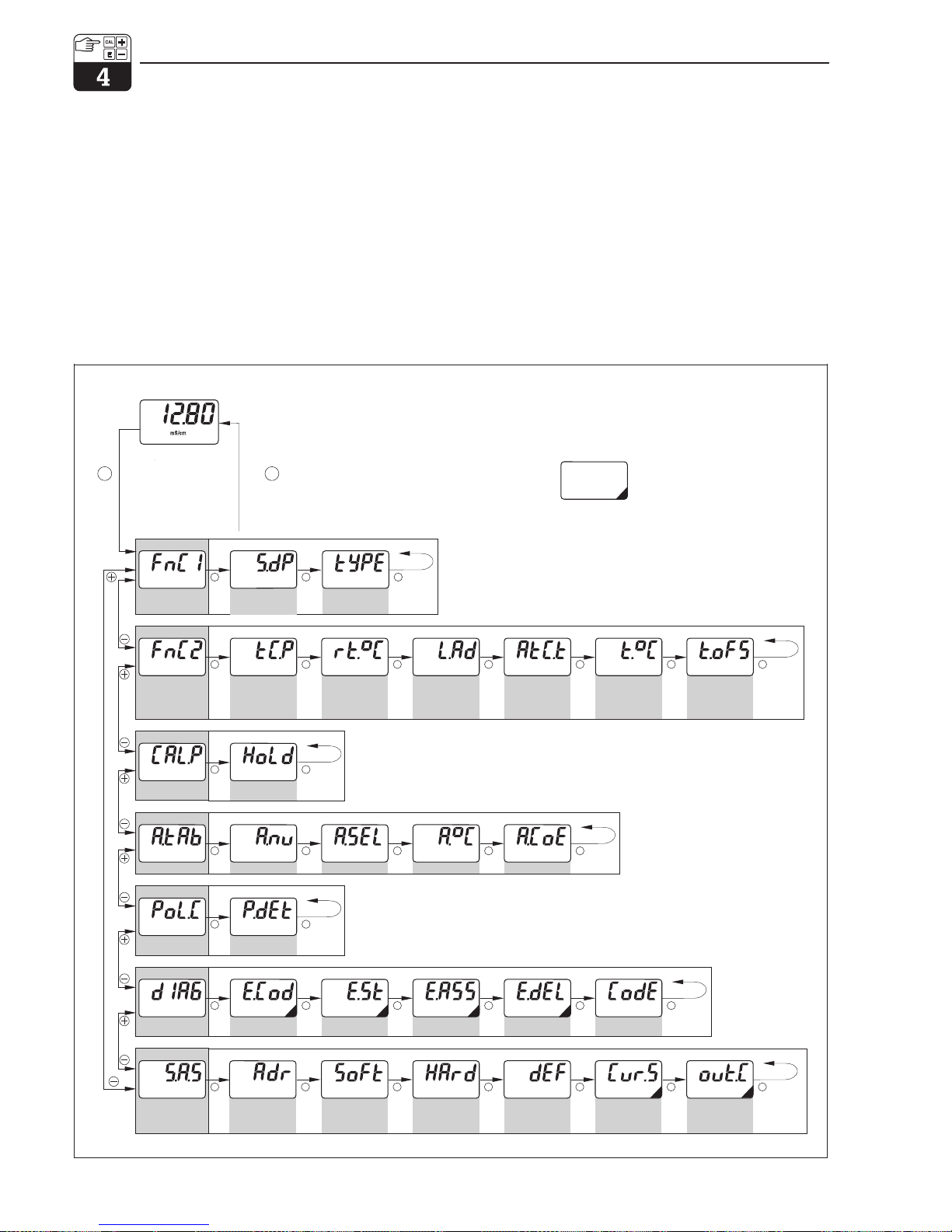
4.7 Operating level 2
Operating level 2 covers all operating functions of the MyPro 431 / CLD 431 not included
in level 1. These functions are arranged in
menus by function group.
• This level is accessed from the normal
measuring mode by pressing and holding
the „F“ key for more than 3 seconds.
• Press the „+“or„–“ key to select the
desired function group.
• The function groups and functions within a
function group are accessed by pressing
the „F“ key.
• When the desired function appears on the
display, the value or selection can be
changed with „+“ or „–“.
• Press the „F“ key to acknowledge and
proceed.
• The „advanced“ operating level is exited
by pressing the „F“ key for more than 3
seconds or automatically after 3 minutes
if no other key is pressed (value is not
stored).
Main parameter
Basic functions
Calibr.param.
a table
Monitoring
Diagnosis
Service and sim.
Signal damping
T.comp. medium
Autom.HOLD
No.of elements
Polarisation detection
Error code Error status Error assignment Error delay Unlock/Lock
Software version
Device address
Hardware version Factory defaults Current simulation Output current
Selection of elem. Temp. value Temp. coeff.
Reference temp. Cable resistance ATC/MTC MTC temperature Temp. offset
Cond./MOhm
nonE LIn
nACL tAb
Pur
on oFF
2...10
on oFF
1 ... 255 0
1
no YES
0 ... 30 0000 .... 9998
00.00 ... 99.99
0 ... 126
00.00 ... 31.99
no InSt
SEnS uSEr
on oFF
4.00 ... 22.00
1 ... number –20 ... 250 [°C] 0.00 ... 10.00
–20 ... 250 [°C] 0.00 ... 50.00 Ω
oFF on t
oFF t..
–20 ... 250 [°C] –20 ... 20 [°C]
Cond rES
Normal meas.mode
>3 s
F
F
F
F
F
F
F
F
F
F
F
F
F F F F F
F FF F F F
F F F
F F F F F
F
F
>3 sor
no key pressed in
> 3 min
F
1...10
MENUESTR.CDR
The displays shown in this overview are examples and
may differ during actual operation.
Functions marked with a blackened
corner are not available in the
PROFIBUS-PA variant.
p. 27
p. 29
p. 31
p. 32
p. 33
p. 33
p. 35
Operation mypro CLM 431 / CLD 431 conductive
26 Endress+Hauser
Page 30
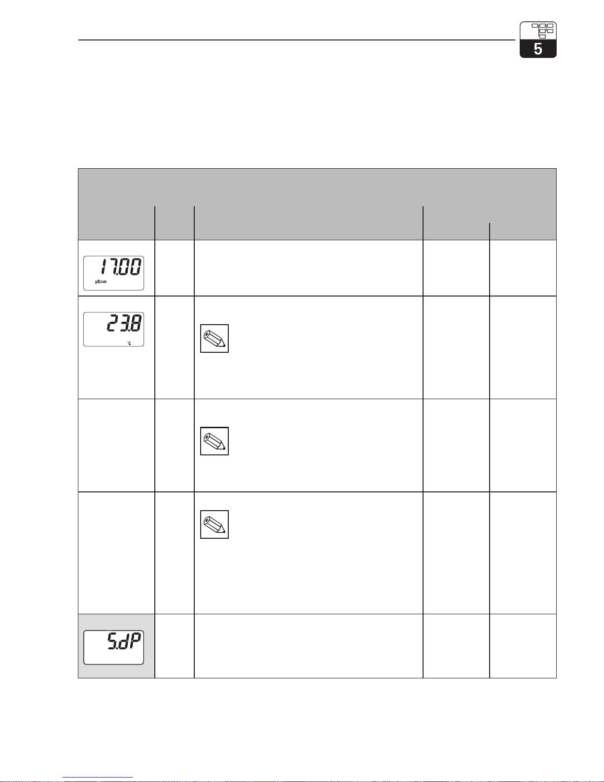
5 Functional description
This chapter contains detailed descriptions of
and information on the individual MyPro func-
tions referred to the matrix representation of
the hand-held terminal or Commuwin II.
5.1 Main parameters
Function group
MAIN PARAMETERS
Function/display
Matrix
VH
1)
Description
Setting
Default Customer
Measured value
VH00Displays the currently measured conductivity or
resistance value.
–
Temperature
VH01Displays the currently measured temperature value (see
chapter 4.6.1).
Note:
This is only displayed if the temperature
measurement is enabled (see VH 17: type of
temperature compensation).
Value range:
–35.0 ... 250.0 °C
–
Operating state
VH02Output of current operating state, e.g. indicates when field
calibration is currently being performed.
Note:
This function is only intended for operation with
the Commuwin II user interface or the
hand-held HART®terminal.
Commuwin: Meas., cal. active, parameter setting
–
Unit of main
parameter
VH03Selects the unit for the parameter measured.
Note:
• This is only relevant for the data transfer
via the interface. The unit on the 4-digit field
display changes automatically based on
the auto range function.
• Depending on operating mode cond. / MΩ
Value range:
µS/cm, mS/cm, S/m
kΩ⋅cm, MΩ⋅cm
µS/cm
or
MΩ⋅cm
Input damping
VH04This function describes the transmitter’s response to the
input signal. The value entered here corresponds to the
number of samples used for averaging.
Value range:
1...10
3
■ Operating level 2
LM431CE5.CHP
mypro CLM 431 / CLD 431 conductive Functional description
Endress+Hauser 27
Page 31
Function group
MAIN PARAMETERS
Function/display
Matrix
VH
1)
Description
Setting
Default Customer
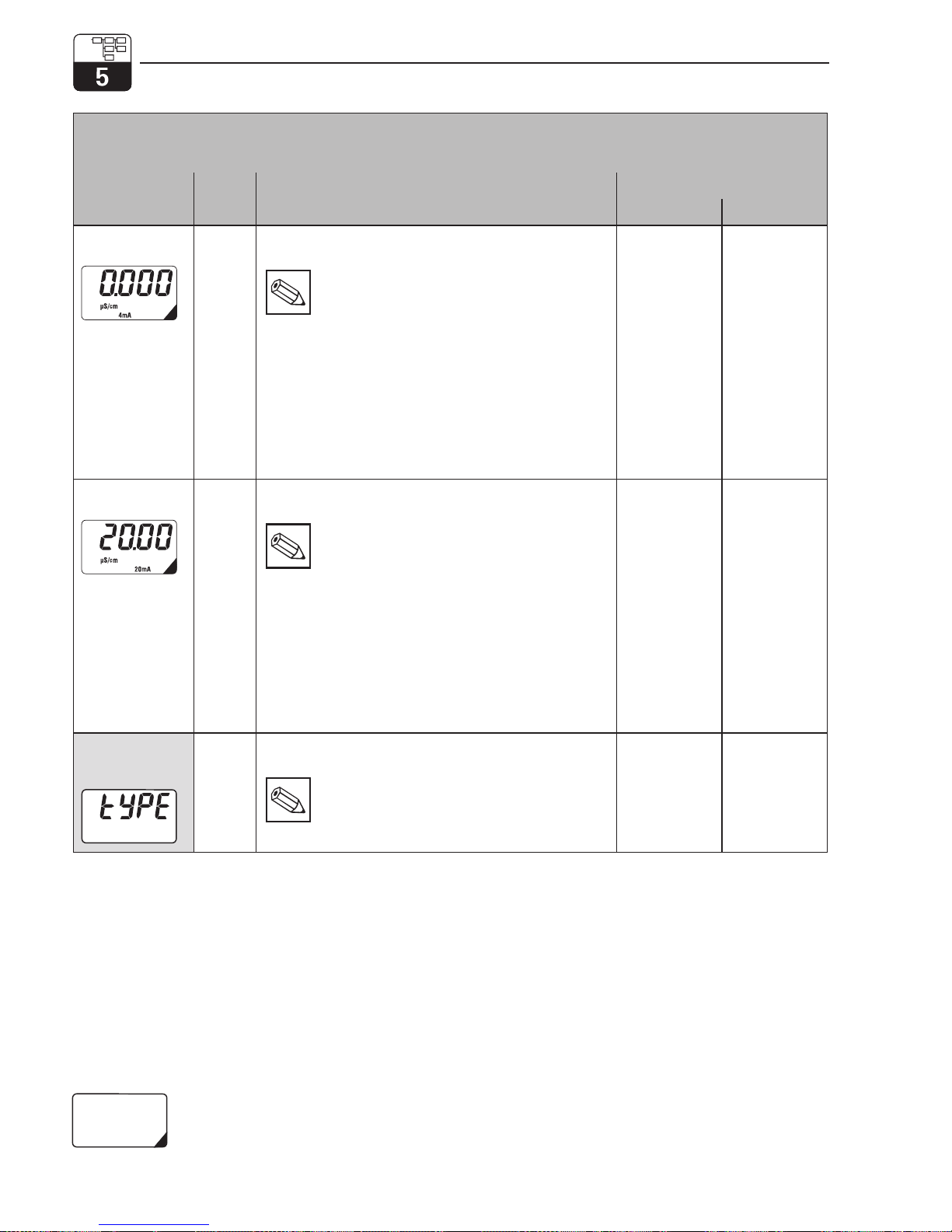
Set
4 mA value
VH05Entry of conductivity or resistance value for a current
value of 4 mA (see chapter 4.6.3).
Note:
A specific minimum distance from the 20 mA
value must be observed.
Value range:
0 ... 60 mS/cm
0...200MΩ⋅cm
Minimum distance:
Meas. value betw. 0 ... 199,9 µS/cm: 20 µS/cm / 25 kΩ⋅cm
Meas. value betw. 200 ... 1999 µS/cm: 200 µS/cm / 0,25 MΩ⋅cm
Meas. value betw. 2 ... 19,99 mS/cm: 2 mS/cm / 2,5 MΩ⋅cm
Meas. value > 20 mS/cm: 20 mS/cm / 25 MΩ⋅cm
0.0 µS/cm
Set
20 mA value
VH06Entry of conductivity or resistance value for a current
value of 20 mA (see chapter 4.6.3).
Note:
A specific minimum distance from the 4 mA
value must be observed.
Value range:
0 ... 60 mS/cm
0...200MΩ⋅cm
Minimum distance:
Meas. value betw. 0 ... 199,9 µS/cm: 20 µS/cm / 25 kΩ⋅cm
Meas. value betw. 200 ... 1999 µS/cm: 200 µS/cm / 0,25 MΩ⋅cm
Meas. value betw. 2 ... 19,99 mS/cm: 2 mS/cm / 2,5 MΩ⋅cm
Meas. value > 20 mS/cm: 20 mS/cm / 25 MΩ⋅cm
20.00 µS/cm
Operating mode
conductivity /
resistance
VH09Sets the transmitter operating mode to conductivity or
resistance measurement.
Note:
Changing the operating modes resets the
current output values to default.
conductivity
or
resistance
■ Operating level 2
Functions marked this way are not available in the Profibus instrument variant.
Functional description mypro CLM 431 / CLD 431 conductive
28 Endress+Hauser
Page 32
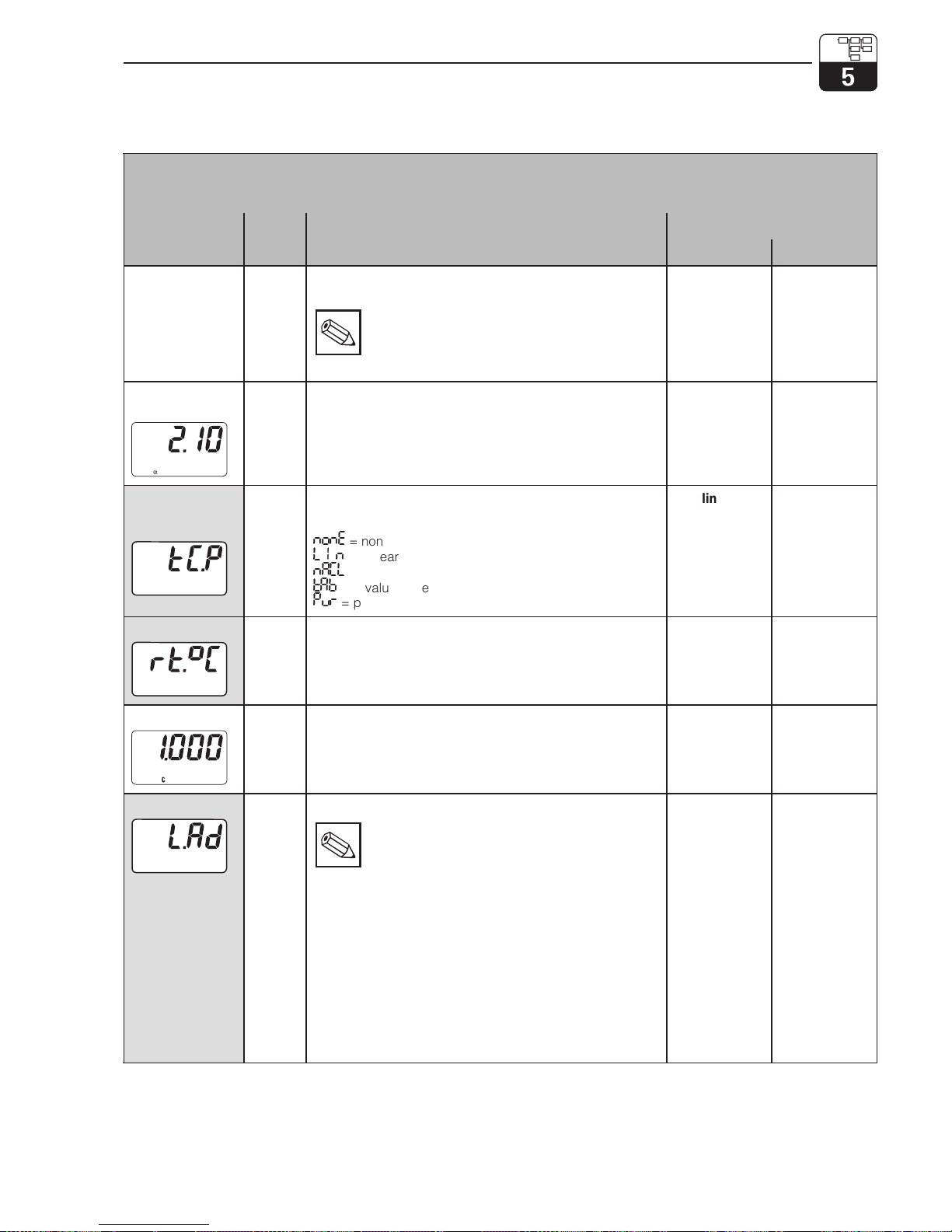
5.2 Basic functions
Function group
BASIC FUNCTIONS
Function/display
Matrix
VH
1)
Description
Setting
Default Customer
Remote
calibration
control
VH10This function controls the calibration sequence when
operated via the interface (see chapter 4.6.4 ).
Note:
The measuring system can be calibrated in
the field or via the interface (hand-held
HART®terminal or Commuwin II).
–
Temperature
coefficient α
VH11Entry of linear temperature coefficient for the process in
measuring mode.
Value range:
0 ... 10 % /K
2.10 % / K
Temperature
compensation
type
VH12Selection of medium temperature compensation type.
Value range:
nonE
= none
LI N
= linear
nACL
= NaCl
tAb
= α value table
Pur
= pure water NaCl
linear
Reference temp.
VH13Reference temperature for automatic temperature
compensation.
Value range:
–35 ... 250 °C
25 °C
Cell constant
VH15Entry of cell constant or information on cell constant
determined during calibration.
Value range:
0.0025 ... 99.99 cm
–1
1cm
–1
Line resistance
VH16Entry of line resistance for conductivity measuring cell.
Note:
The line resistance does not affect the accuracy
in the case of measured values below 1 mS.
With measured values above 5 mS and line
lengths (CYK 71) exceeding 10 m, the error is
greater than 0.5% of the measuring value
and therefore requires compensation.
Note:
The total line resistance of measuring cable
CYK 71 is 0.17 Ω/m.
Value range:
0.00 ... 50 ohms
0
■ Operating level 2
LM431CE5.CHP
mypro CLM 431 / CLD 431 conductive Functional description
Endress+Hauser 29
Page 33
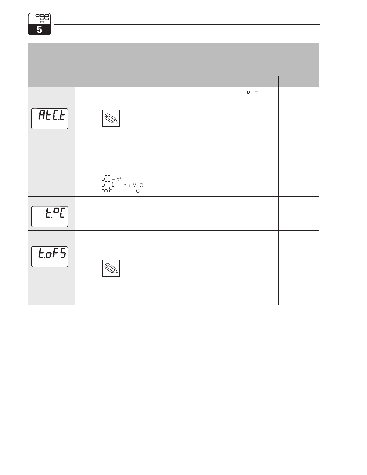
Function group
BASIC FUNCTIONS
Function/display
Matrix
VH
1)
Description
Setting
Default Customer
Temperature
compensation
type
VH17Switches the temperature measurement on/off and
toggles between manual and automatic temperature
compensation (MTC/ATC).
Note:
• If set to „off+MTC“, the preset MTC
temperature is used for compensation
• If set to „on+MTC“, the temperature can be
additionally measured via a temperature
sensor and output via the HART®interface
or in the field
• If set to „on+ATC“, the value measured by
the temp. sensor is used for compensation
Value range:
oFF
=off+MTC
oFF.t
= on + MTC
on.T
= on + ATC
on + ATC
MTC temp.
VH18Entry of reference temperature for manual temperature
compensation.
Value range:
–35.0 ... 250.0 °C
25.0 °C
Temperature
offset
VH19Adjustment of temperature measurement by an offset
value. Entry of an offset value or of the offset determined
during calibration (at operating level 1, this value can only
be viewed but not edited).
Note:
Only exists if temperature measurement
has been switched on (see VH 17
„Temperature compensation type“).
Value range:
–20.0 ... 20.0 °C
0.0 °C
■ Operating level 2
Functional description mypro CLM 431 / CLD 431 conductive
30 Endress+Hauser
Page 34
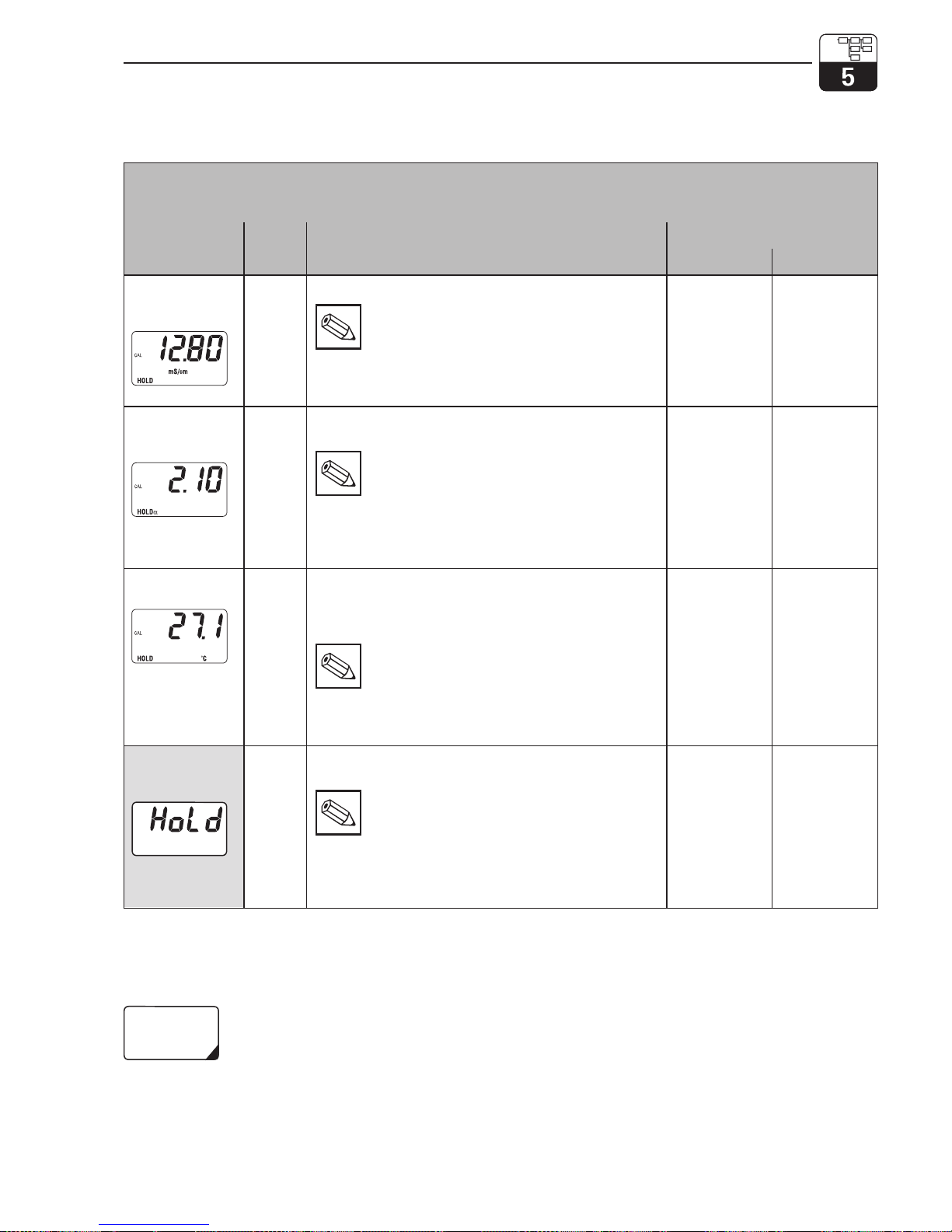
5.3 Calibration parameters
Function group
CALIBRATION PARAMETERS
Function/display
Matrix
VH
1)
Description
Setting
Default Customer
Entry of
calibration
solution
VH20Conductivity of calibration solution.
Note:
The unit is µS/cm or mS/cm.
Value range:
0.000 µS/cm to 9999 mS/cm
1000 µS/cm
Temperature
coefficient α of
calibr. solution
VH21Temperature coefficient of calibration solution for
calibration with automatic temperature compensation.
Note:
The α value of the solution is temperaturedependent and must be determined for the
current calibration temperature.
Value range:
0.00 ... 10.00 % / K
2.10 % / K
Temperature of
calibr. solution
VH23Temperature calibration: Field for entry of current
calibration temperature. The temperature offset is
automatically computed from this and displayed in field
VH 19 “Temperature offset”.
Note:
• With ATC: Entry of actual temperature
• With MTC: Entry of MTC calibration temp.
Value range:
–35 ... 250 °C
–
Automatic
HOLD during
calibration
VH29Activates or deactivates the automatic HOLD function for
the current output during calibration.
Note:
Hold during calibration is always active for
resistance measurement.
Value range:
Autom. HOLD during calibration off
Autom. HOLD during calibration on
on
■ Operating level 2
Functions marked this way are not available in the Profibus instrument variant.
LM431CE5.CHP
mypro CLM 431 / CLD 431 conductive Functional description
Endress+Hauser 31
Page 35
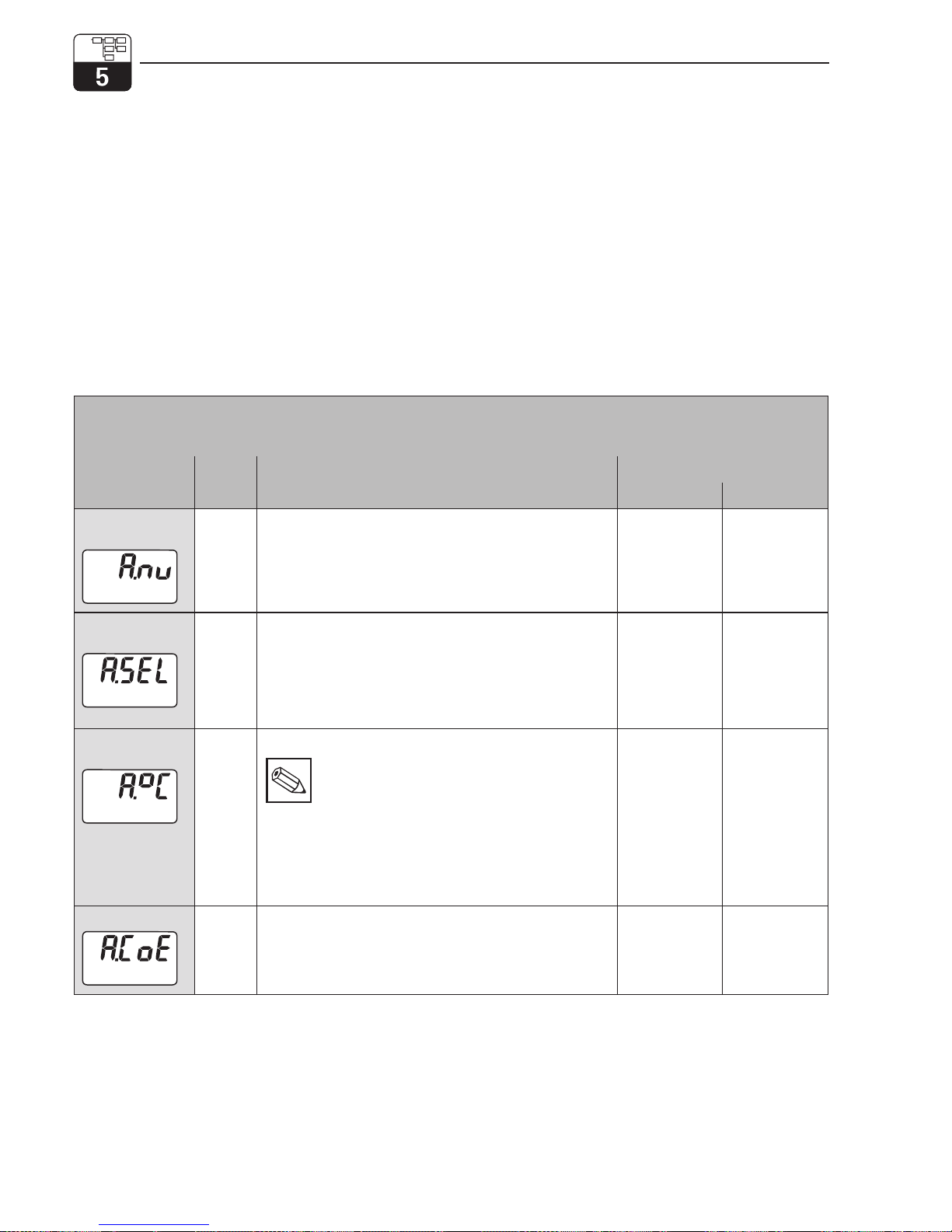
5.4
Alpha table
In order to implement a special, mediumspecific temperature compensation function,
a table is stored in the MyPro CLM 431 / CLD
431. The α characteristic is entered in a table
which may contain 2 to 10 elements. Each
table element consists of an α value and the
associated temperature.
The α table is activated via the “tab” mode in
matrix position VH 12. However, the activation
should not be performed unless the values
have been edited (VH 60 ff) since changes in
the α table become effective immediately
(resulting in error message 150 in position
VH 62).
Programming sequence for αtable:
1. Enter number of elements (VH 60)
2. Select element 1 (VH 61)
3. Enter temperature value 1 (VH 62)
4. Enter αvalue 1 (VH 63)
5. Repeat steps 2 to 4 for all other
elements of the table
■ Operating level 2
Function group
αTABLE
Function/display
Matrix
VH
1)
Description
Setting
Default Customer
Number of
elements
VH60Entry of number of table elements.
Value range:
2...10
2
Selection of
element
VH61Programming of the selected table element starts with the
selection of the element. This is followed by the entry of
the temperature value and corresponding α value for the
table element.
Value range:
1 ... number of elements
1
Temperature
value
VH62Temperature value of current table element.
Note:
The temperature values must increase from one
element to the next. The required minimum
distance between temperature values is 10 K.
Error message E150 indicates an incorrect
temperature entry.
Value range:
–35 ... 250 °C
0
αvalue
VH63Temperature coefficient of current table element.
Value range:
0.0 ... 10.00 % / K
2.10 % / K
Functional description mypro CLM 431 / CLD 431 conductive
32 Endress+Hauser
Page 36
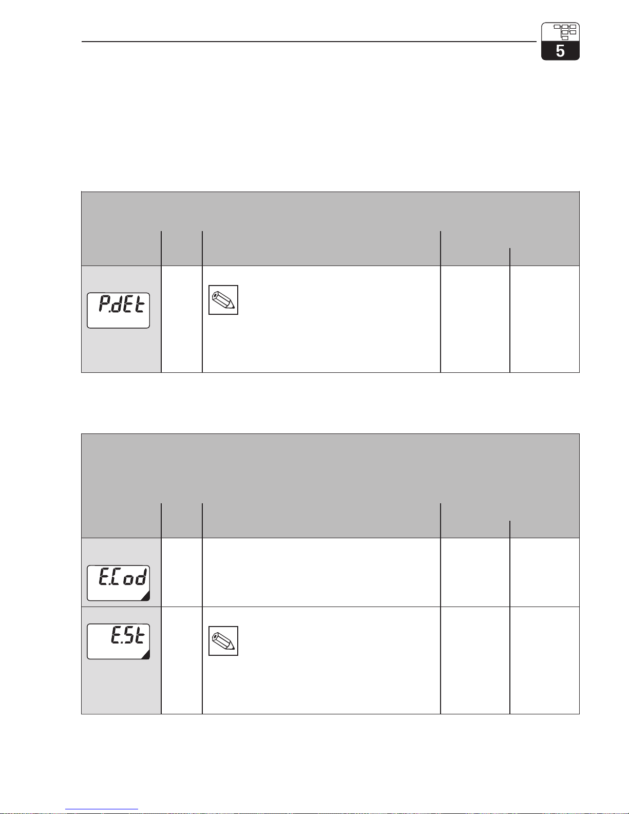
5.5 Polarisation detection
Conductive conductivity measuring cells are
characterised by a limited measuring range
which mainly depends on the cell constant.
However, the exact application range limits
of a measuring cell also depend on other
factors, such as, for example, frequency of
measurement, electrode material, coating on
electrode and medium to be measured,
all of which complicate the determination of
the application limit. The MyPro CLM 431 /
CLD 431 transmitter employs a procedure
permitting direct measurement of the polarisation effect. This method evaluates signals and
issues an alarm whenever the cell constant
has changed by more than 5% due to polarisation effects.
5.6 Diagnosis
Function group
DIAGNOSIS
This function group can be used to define
the error current assignments for each
individual error and to disable (lock) field operation.
Function/display
Matrix
VH
1)
Description
Setting
Default Customer
Selection of
diagnostic code
VH80Selection of a diagnostic (error) code (see chapter 7.2).
Value range:
E 1 ... E 150
1
Error status
VH81Display of status for selected diagnostic code.
Note:
The error status can be evaluated with the
hand-held HART®terminal or with the
Commuwin II user interface.
Value range:
0 = inactive
1 = active
depending on
code
■ Operating level 2
Function group
BASIC MONITORING FUNCTIONS
Function/display
Matrix
VH
1)
Description
Setting
Default Customer
Polarisation
monitoring
VH70Switches the polarisation monitoring function on or off.
Note:
If polarisation monitoring is on and polarisation
is detected, then error message E071
„Polarisation error“ is signalled (does not
appear for MΩ measurement)
Value range:
On
Off
on
LM431CE5.CHP
mypro CLM 431 / CLD 431 conductive Functional description
Endress+Hauser 33
Page 37
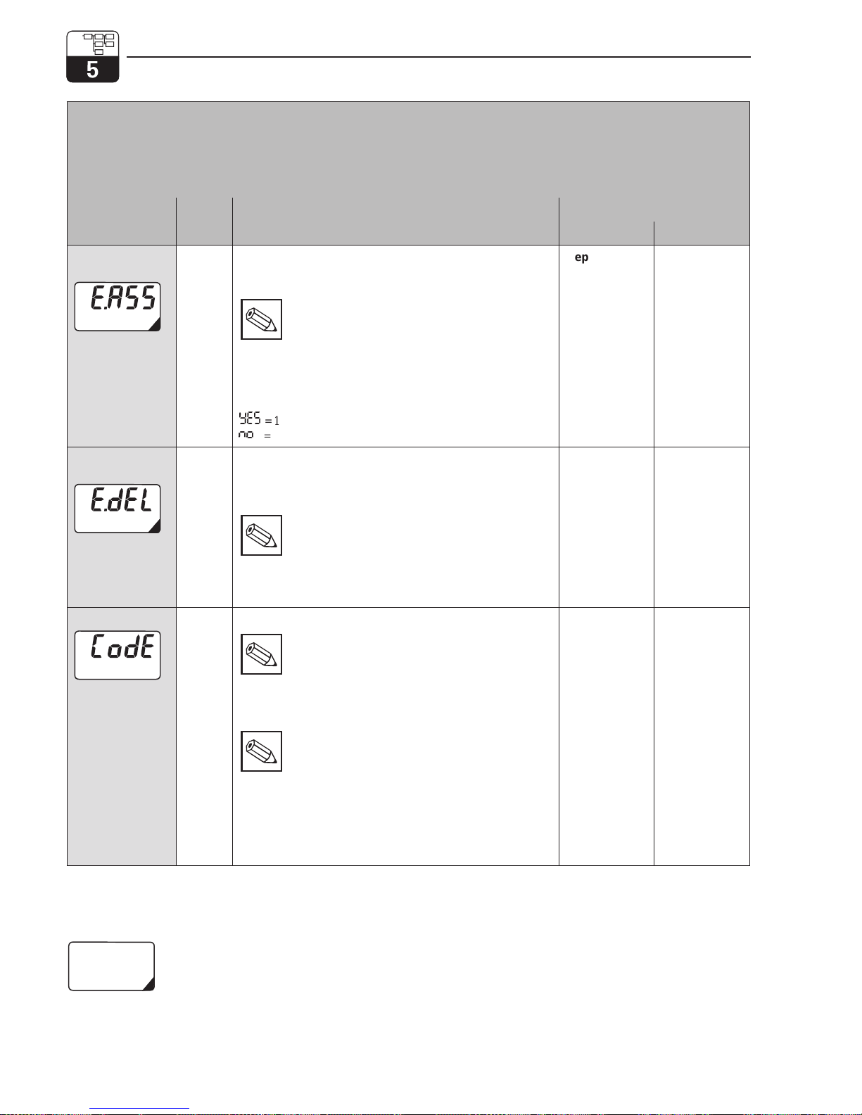
Function group
DIAGNOSIS
This function group can be used to define
the error current assignments for each
individual error and to disable (lock) field operation.
Function/display
Matrix
VH
1)
Description
Setting
Default Customer
Error
assignment
VH82This function is used to define whether or not an error
current of 22 mA is output for the selected error code on
the current output.
Note:
If set to „yes“ (effective), an error current is
output for an error set by the MyPro.
A diagnostic code with the setting „no“
(not effective) has no effect on the current
output.
Value range:
Yes
=1
no
=0
depending on
code
Error current
delay
VH83Sets the delay for a diagnostic code for which the error
current assignment „yes“ (effective) has been set. If such
a diagnostic code is set by the MyPro, this error becomes
effective as an error current after the delay defined here.
Note:
This delay applies to all
diagnostic codes.
Value range:
0 ... 30 s
2s
Unlock/Lock
VH89Unlock/locks field operation (see chapter 4.5).
Note:
Field operation can be locked and unlocked
with the hand-held HART®terminal, with the
Commuwin II user interface or in the field.
Locking via the keypad has precedence over
software locking.
Note:
0097 = instrument unlocked (any other
entry locks the instrument)
9999 = instrument locked in field with key
combination “+” and “F” (unlocking via
the HART®interface or via operating
level 2 is not possible)
Value range:
0000 ... 9998
0097
■ Operating level 2
Functions marked this way are not available in the Profibus instrument variant.
Functional description mypro CLM 431 / CLD 431 conductive
34 Endress+Hauser
Page 38
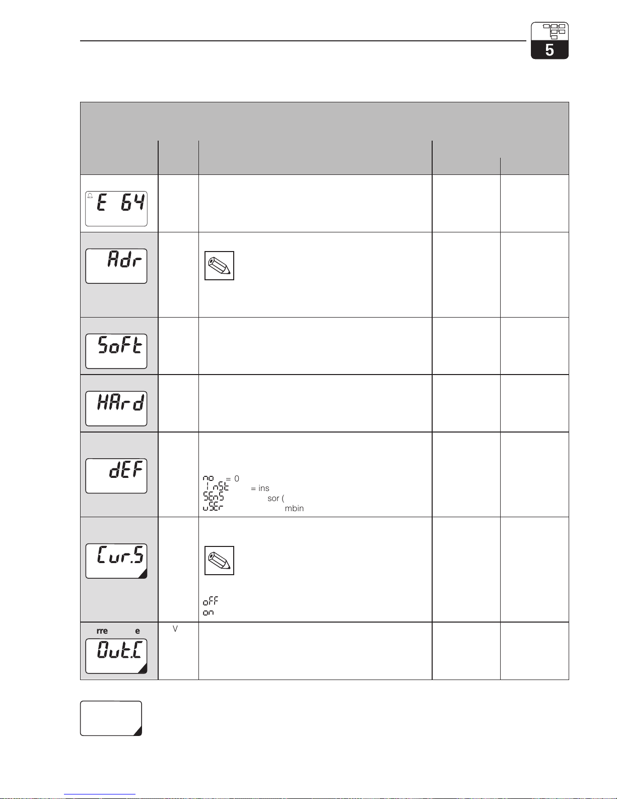
5.7 Service and simulation
Function group
SERVICE/SIMULATION
Function/display
Matrix
VH
1)
Description
Setting
Default Customer
Diagnostic code
VH90Displays the active diagnostic codes with the highest
priority levels (see chapters 4.6.2 and 7.2).
Value range:
E1...E150
–
Device address
VH 92 Entry of device address.
Note:
Only available for PROFIBUS-PA.
Value range:
0 ... 126
126
Software version
VH93Displays the software version of the instrument.
depends on
instrument
version
Hardware version
VH94Displays the hardware version of the instrument.
depends on
instrument
version
Factory settings
(set default)
VH95This function is used to selectively reset the data areas of
the instrument to the factory settings.
Value range:
no
= 0 = no reset
InSt
= 1= instrument (data specific to instrument)
SEnS
= 2 = sensor (data specific to sensor)
uSEr
= 3 = user (combination of 1+2)
no
Output current
simulation
VH98This function is used to switch the output current
simulation on or off.
Note:
Reset back to „0“ (simulation off) after
simulation.
Value range:
off
=0=off
on
=1=on
0
Current value
VH99Entry of a current value (independent of the measurement)
to be output at the current output.
Value range:
4.00 ... 22.00 mA
10 mA
■ Operating level 2
Functions marked this way are not available in the Profius variant.
LM431CE5.CHP
mypro CLM 431 / CLD 431 conductive Functional description
Endress+Hauser 35
Page 39
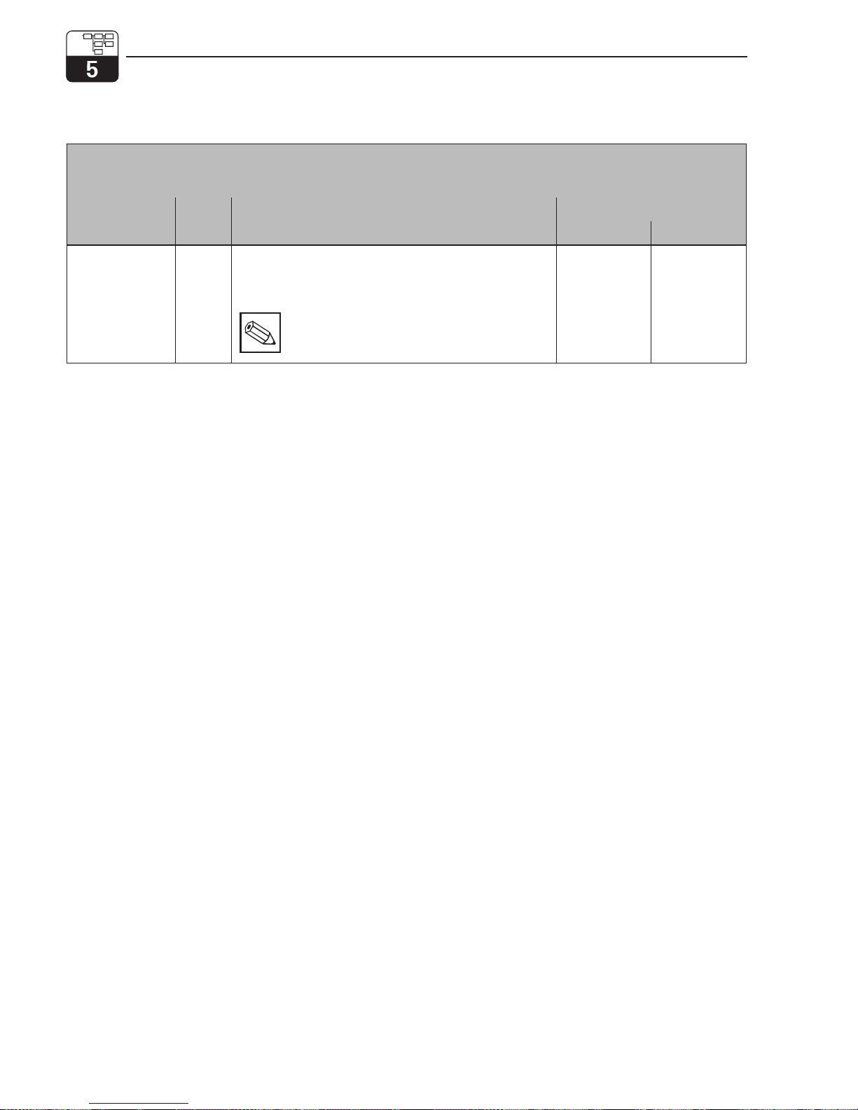
5.8 User info
Function group
USER INFO
Function/display
Matrix
VH
1)
Description
Setting
Factory Customer
Tag number
VHA0Entry of a measuring point designation (tag number).
Value range:
Any sequence of 8 alphanumeric characters.
Note:
This function is only available for operation via
the Hart interface but not via PROFIBUS.
“”
(8 spaces)
■ Operating level 2
Functional description mypro CLM 431 / CLD 431 conductive
36 Endress+Hauser
Page 40
6 Interfaces
6.1
HART
6.1.1
HART
with hand-held terminal or HARTCommunicator
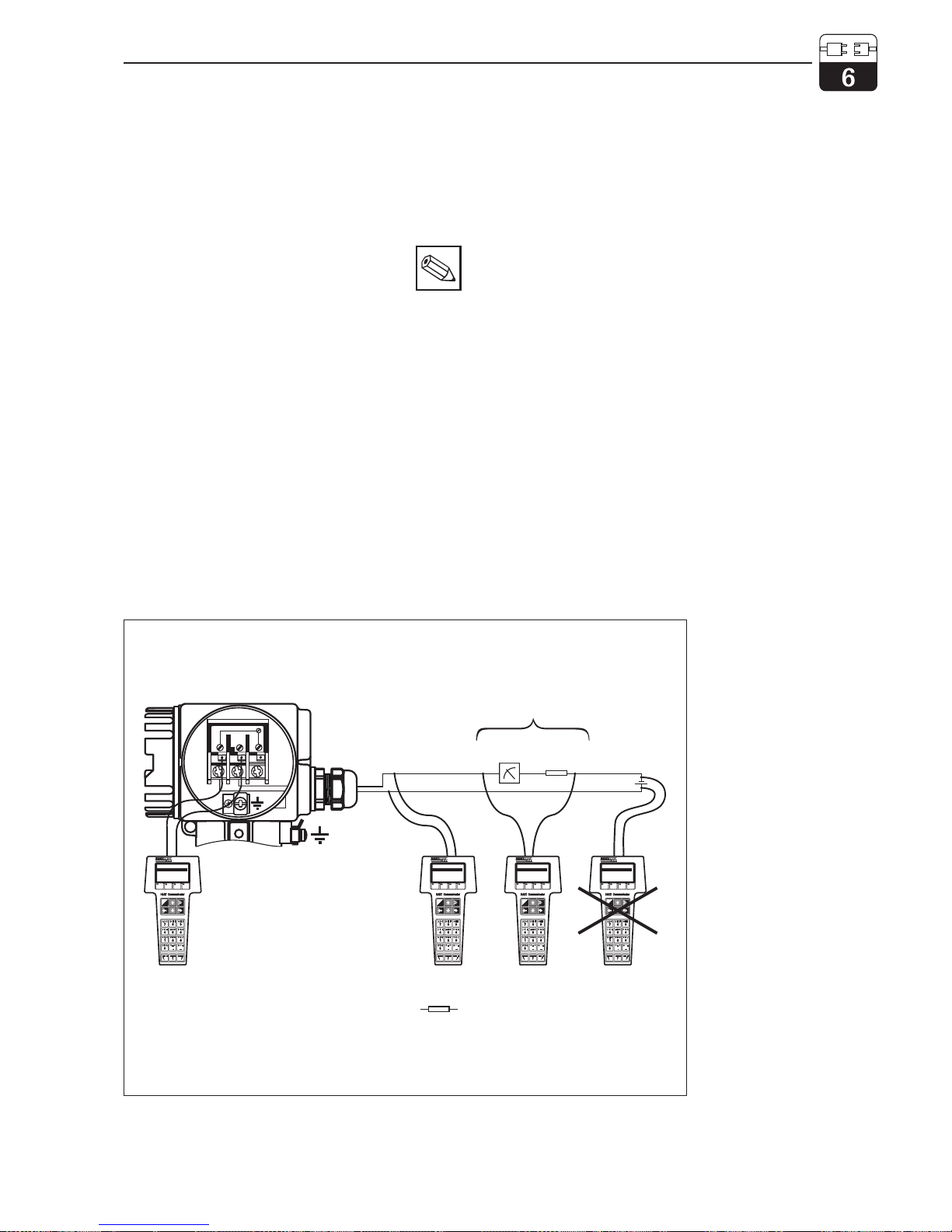
In addition to field operation, the MyPro
CLM 431 / CLD 431 transmitter can also be
accessed via the universal hand-held terminal
DXR 275 or a PC with a HARTmodem
(Commubox) using the HARTprotocol to
query or change parameter settings. This
chapter contains essential information on:
• electrical connection
• operation of HART Communicator
• E+H operating matrix for HART
Note:
Refer to the DXR 275 operating
instructions for details on the handheld HART terminal.
Connection of hand-held terminal DXR 275
There are two alternatives for connecting the
hand-held terminal (see fig. 6.1.):
• Direct connection to the measuring transmitter via terminals 1 and 2
• Connection via the 4 ... 20 mA analog
signal line
In both cases, the measuring circuit must
have a resistance of at least 250 Ω between
the power source and the hand-held terminal.
The max. load at the current output depends
on the supply voltage. The measuring transmitter input voltage for the maximum current
consumption of 22 mA must be at least
12 V DC.
4...20 mA
Test
1
3
2
+
0000
HARTHandterminal
1 Offline
3 Transfer
4 Frequenzgerät
5Extras
2 Online➔
I
O
HARTHandterminal
1 Offline
3 Transfer
4 Frequenzgerät
5Extras
2 Online➔
I
O
HARTHandterminal
1 Offline
3 Transfer
4 Frequenzgerät
5Extras
2 Online➔
I
O
HARTHandterminal
1 Offline
3 Transfer
4 Frequenzgerät
5Extras
2 Online➔
I
O
any connected device/resistance
Min. 250 Ω
4...20 mA
BE018Y40.CDR
Fig. 6.1
Electrical connection of
hand-held HARTterminal
LM431CE6.CHP
mypro CLM 431 / CLD 431 conductive Interfaces
Endress+Hauser 37
Page 41
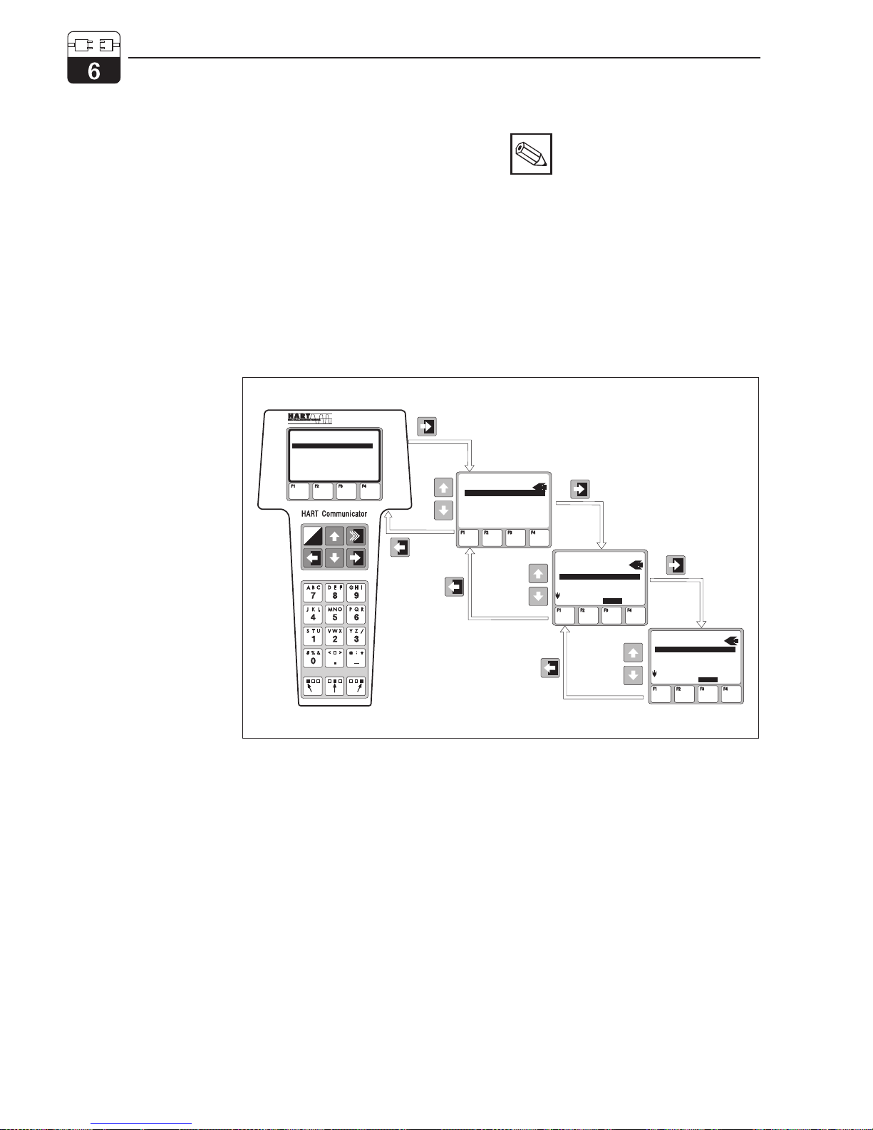
Operation of MyPro CLM 431 / CLD 431 with the HARTCommunicator
Operating the MyPro CLM 431 / CLD 431
measuring system via the hand-held terminal
is quite different from field operation via the
pushbuttons on the keypad. When using the
HARTCommunicator, all MyPro CLM 431
functions are selected at different menu levels
(see figure 6.2) and with the aid of a special
E+H operating menu (see figure 6.3).
Note:
• The MyPro measuring instrument
can only be controlled with a
HARTCommunicator if the proper software (DD = device description of MyPro CLM 431 / CLD
431) is installed in the Communicator. If this is not the case, the
memory module may have to be
replaced, or the software may
have to be adapted. Contact E+H
Service if you have any questions.
• All MyPro functions are described
in detail in chapter 5.
HARTHANDTERMINAL
1 OFFLINE
3 TRANSFER
4 FREQUENCY DEVICE
5 EXTRAS
2 ONLINE➔
I
O
MyProLFC: ABC0001
ONLINE
2 DEVICEDATA
3 HART OUTPUT
4 PV 1000 mS/cm
5 AO 12.00mA
1 MATRIXGROUP SEL.➔
MyProLFC: ABC0001
MATRIXGROUP SEL.
1 MAIN PARAMETER
3 CALIBR. PARAMETER
4 ALPHA TABLE
5 POL. CHECK
2 MAINFUNCTIONS➔
MyProLf: ABC0001
MAINFUNCTION
2 TEMP. COEFFICIENT
3 Tc MEDIUM
4 CELLCONSTANT
5 CABLERESISTANCE
1 CALIBRATION➔
HOME
HOME
Fig. 6.2
Operation of hand-held
HART terminal
Procedure:
1. Switch on the hand-held terminal:
a) Measuring instrument not connected
➜ The HART
main menu appears. This menu
level appears for any HART
programming, i.e.
independent of the instrument type. Refer to the
„Communicator DXR 275“ operating instructions
for further information.
b) Measuring instrument is connected ➜ The program
goes directly to the „Online“ menu level.
The „Online“ menu level is used to display the current data
measured, such as conductivity, temperature, etc., and also
allows you to access the MyPro CLM 431 / CLD 431 operating matrix via the „matrix group selection“ (see figure 6.2). All
function groups and functions accessible through HART are
displayed in this matrix in a systematic arrangement.
2. The function group is selected using „matrix group
selection“ (e.g. basic functions), and then the
desired function, e.g. remote calibration. All
settings or numeric values relating to the function
are immediately displayed.
3. Enter numeric value or change setting as required.
4. Press function key „F2“ to call up „SEND“.
Press the F2 key to transfer all the values entered/
settings changed with the hand-held terminal to the
MyPro CLM 431 / CLD 431 measuring system.
5. Press the HOME function key „F3“ to return to the
„Online“ menu level. Here, you can read the current
values measured by the MyPro CLM 431 / CLD 431
instrument with the new settings.
Interfaces mypro CLM 431 / CLD 431 conductive
38 Endress+Hauser
Page 42
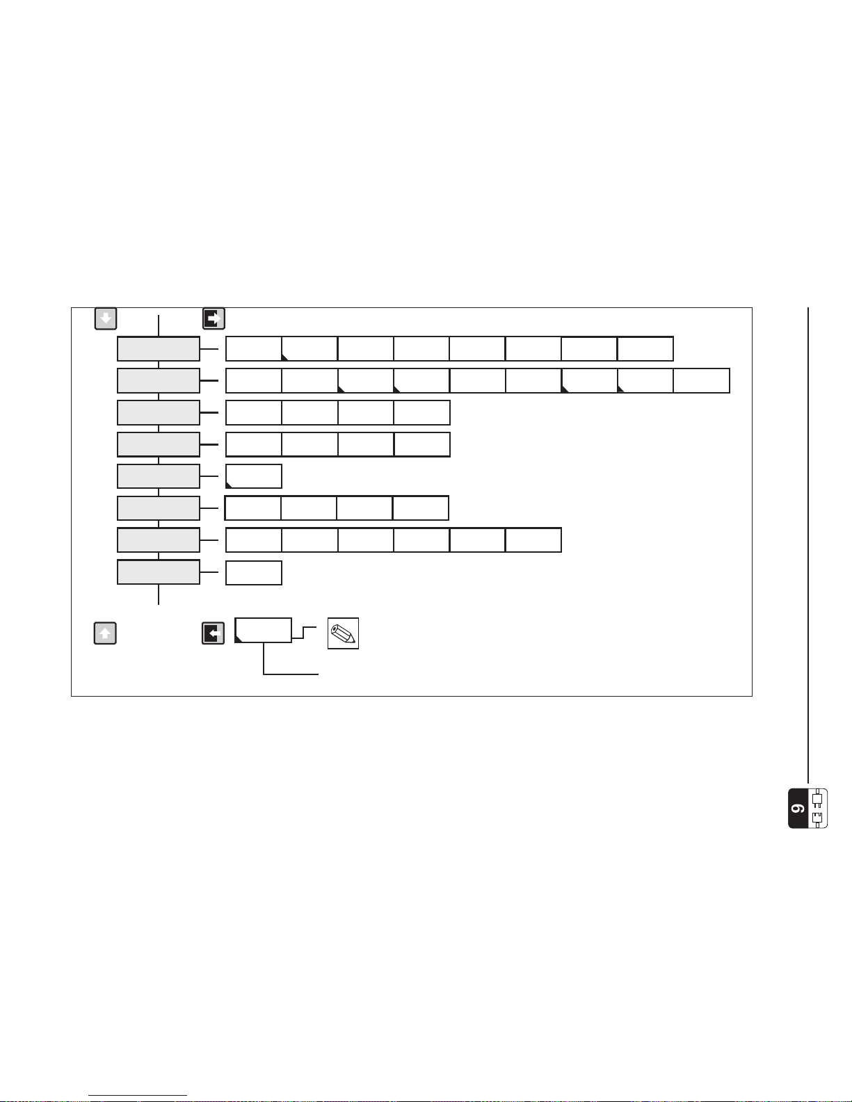
HART
operating matrix
MAIN
PARAMETERS
Meas. point
(tag number)
Software
version
Error code
No. of elements
Pol. alarm
Element selection
Hardware
version
Current
simulation
Defaults
Output current
T of solution
c
Cond. of solution
Temp. of solution
Auto hold dur. cal.
Cal. (contr. field)
Operating state
Temp. coefficient
Meas. value unit
T of medium
c
Reference temp.
Cell constant
Temperature
Meas. value
Signal damping
Value for
4mA
Value for
20 mA
BASIC
FUNCTIONS
CALIBR.
PARAMETERS
ALPHA
TABLE
POL.
MONITORING
DIAGNOSIS
SERVICE
SIMULATION
USER INFO
Mode: cond./MΩ
Cable resistance
Temp. compens.
MTC temp. entry
Temp. correction
Temperature
value
Alpha value
Error status
Error current
delay
Locking
Note:
These functions only appear if other functions
have been configured accordingly.
In some cases, the MyPro CLM 431 / CLD 431 function designations
for the HART terminal may deviate slightly from the designations
listed in chapter 5.
....................
Error current
assignment
BA018E42.CDR
Fig. 6.3
If the instrument has been
locked in the field, the
parameters cannot be
changed via the
hand-held terminal (see
chapter 4.5)
HART
operating matrix
for MyPro CLM 431 /
CLD 431 (conductive
conductivity
measurement)
LM431CE6.CHP
mypro CLM 431 / CLD 431 conductive Interfaces
Endress+Hauser 39
Page 43
6.1.2
HART
with Commuwin
Description
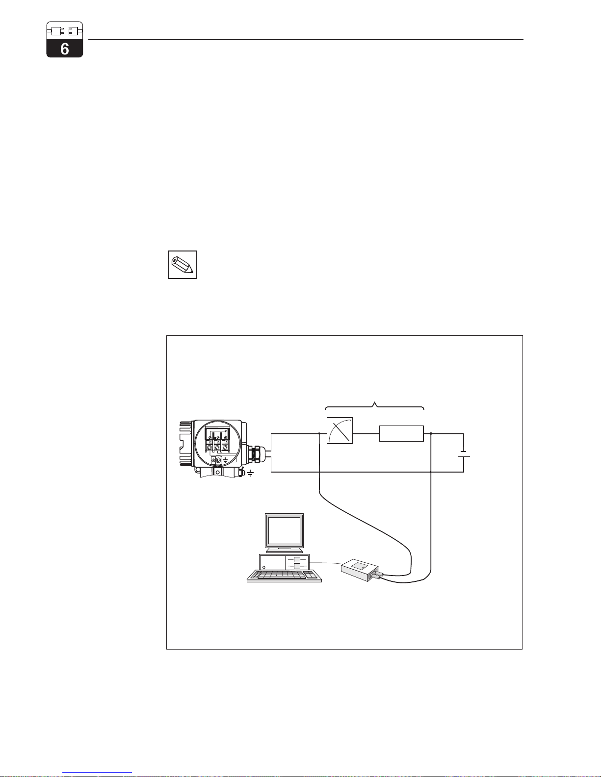
The MyPro CLM 431 / CLD 431 measuring
transmitter can also be operated via its
HARTinterface using Commuwin II.
Commuwin II is a graphical control program
for intelligent measuring instruments and can
handle various communication protocols. The
program supports the following functions:
• On-line and off-line measuring transmitter
parameter changes
• Loading and saving of instrument data
(upload/download)
Note:
Refer to the Commuwin II operating
instructions (BA 124F/00/en) for a
detailed description.
A program extension additionally supports
recording of measured values on a line
recorder.
Commuwin offers two alternatives for operation and parameter changes (instrument
data menu):
• Graphical operation
• Matrix operation
4...20 mA
4...20mA
Test
1
3
2
+
0000
MyPro CLM 431 /
CLD 431
any connecteddevice
or resistance
min. 250 Ω
Supply voltage
17,5 ... 30 V DC
Commuwin II
Commubox
FXA 191
BA018Y43.CDR
Fig. 6.4
Electrical connection
of the Commubox
Interfaces mypro CLM 431 / CLD 431 conductive
40 Endress+Hauser
Page 44
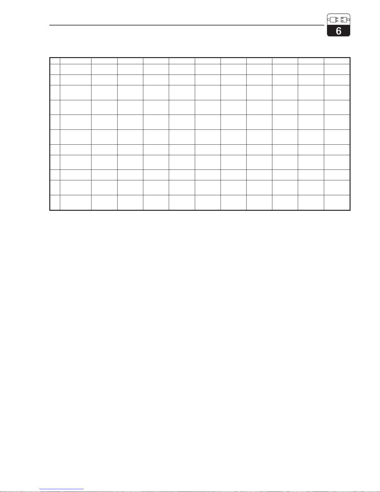
Commuwin II operating matrix
6.2 PROFIBUS-PA
Please refer to separate operating
instructions for instruments equipped
with the PROFIBUS interface.
H0 H1 H2 H3 H4 H5 H6 H7 H8 H9
V0
MAIN
PARAMETERS
Meas. value Temperature
Operating
state
Unit of
meas. value
Signal
damping
Value for
4 mA
Value for
20 mA
Oper. mode
cond./MΩ
V1
BASIC
FUNCTIONS
Calibration
(control field)
Temp.
coefficient
α value
of medium
Reference
temperature
Cell constant
Line
resistance
Temperature
compens.
Entry of
MTC temp.
Temperature
correction
V2
CALIBR.
PARAMETERS
Conductivity
of solution
αvalue
of solution
Temperature
of solution
Autom.
HOLD dur.
calibration
V3
V4
V5
V6
ALPHA
TABLE
Number of
elements
Selection of
elements
Temperature
value
Alpha value
V7
POL.
MONITORING
Pol. alarm
V8
DIAGNOSIS
Selection of
error code
Error
Status
Error
assignment
Error current
delay
Unlock/Lock
V9
SERVICE/
SIMULATION
Error
code
Software
version
Hardware
version
Factory
defaults
Current
output
simulation
Current value
VA
USER
INFO
Meas. point
(tag number)
LM431CE6.CHP
mypro CLM 431 / CLD 431 conductive Interfaces
Endress+Hauser 41
Page 45
7 Troubleshooting
7.1 Error indication
The MyPro CLM 431 / CLD 431 indicates
errors by means of an alarm symbol flashing
on the display. It also outputs an error current
of 22 mA +/- 0.5 mA at the current output if
configured accordingly (VH 80 – 83).
The error can then be identified in the diagnostic parameters via the diagnostic code.
Up to five entries are listed according to
priority.
7.2 Diagnostic codes (error codes)
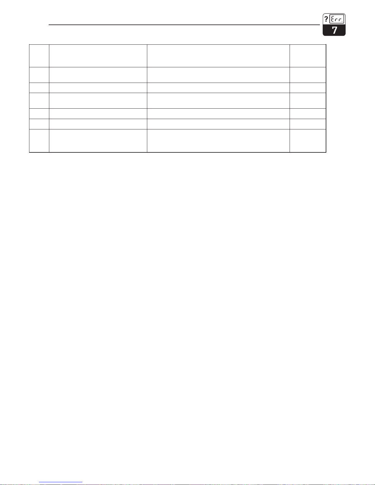
The following table describes the diagnostic/error codes of this instrument variant.
The default error current assignment (active
or not active) for each code is also listed.
Failure
no.
Display Measures Error current
assignment
(default)
E1
EEPROM memory error
Switch instrument off and on again,
return instrument to your local Endress+Hauser sales
agency or exchange instrument.
active
E2
Instrument not adjusted, adjustment
data invalid, no user data available or
user data invalid (EEPROM error)
active
E7
Transmitter malfunction
active
E10
No temperature sensor connected or
temperature sensor short-circuited
(temperature sensor faulty)
Check temperature sensor and connections;
if necessary, check instrument and measuring cable with
temperature simulator.
active
E36
Measuring cell calibration range
exceeded
Recalibrate measuring cell; if necessary, check measuring
cell and connections; check instrument and measuring
cable with conductivity simulator.
active
E37
Below measuring cell calibration range
active
E45
Calibration aborted Repeat calibration. active
E46
Current output parameter limits
interchanged
Set value for 20 mA to a value > value for 4 mA. active
E55
Below main parameter measuring
range
Immerse sensor in conductive medium. active
E57
Main parameter measuring range
exceeded
Check measurement, process control and connections; if
necessary, check instrument and measuring cable with
simulator.
active
E59
Below temperature measuring range
active
E61
Temperature measuring range
exceeded
active
E63
Below current output range
Check configuration; if necessary, check instrument and
measuring cable with simulator.
not active
E64
Current output range exceeded Check measured value and current assignment.
not active
E71
Inaccurate measurement/polarisation
Clean measuring cell; check table; select suitable
measuring cell.
active
E77
Temperature outside α value table
range
Check process / table assignment.
not active
Troubleshooting mypro CLM 431 / CLD 431 conductive
42 Endress+Hauser
Page 46
Failure
no.
Display Measures Error current
assignment
(default)
E80
Current output parameter range too
small
Spread current output. not active
E100
Current simulation active Choose correct current output parameter.
not active
E101
Service function active
Switch off service function or switch instrument off and on
again.
not active
E106
Download active Wait for download to be finished. not active
E116
Download error Repeat download.
active
E150
Distance between temperature values
in α value table too small or not
monotonously increasing
Enter correct values in αvalue table (minimum distance
between temperature values of 10 K required).
not active
LM431CE7.CHP
mypro CLM 431 / CLD 431 conductive Troubleshooting
Endress+Hauser 43
Page 47

8 Service and maintenance
8.1 Cleaning
We recommend using commercially available
cleaning agents to clean the front of the instrument.
The instrument front is resistant to
(DIN 42 115 test method):
• alcohol (short-term)
• diluted acids (max. 2 % HCI)
• diluted lyes (max. 3 % NaOH)
• soap-based household detergents
Note:
Do not use concentrated mineral
acids or lyes, benzyl alcohol,
methylene chloride or high-pressure
steam to clean the front panel.
8.2 Repairs
Repairs may only be carried out by the
manufacturer or through the Endress+Hauser
service organization.
An overview of the Endress+Hauser service
network can be found on the back cover of
these operating instructions.
Service and maintenance mypro CLM 431 / CLD 431 conductive
44 Endress+Hauser
Page 48

9 Accessories
The following accessories may be ordered
separately:
• Transmitter power supply units
– RN 221 power separator (non-Ex)
– RN 221 Z power separator (Ex)
– NX 9120 power supply (1 channel,
non-Ex)
– NX 9121 power supply unit (3 channels,
Ex)
– 1-channel transmitter power supply
units with galvanically separated power
output
Output voltage: typ. 24 V DC ±1 V
Output current: max. 33 mA
Current limiting: 38 mA ±5 mA
• Hand-held HARTterminal DXR 275
The hand-held terminal communicates with
any HART-compatible unit via the 4 ... 20 mA
line.
Refer to the E+H sales agency in your area
for details and further information on programming (see back cover of these operating instructions for addresses).
• Commuwin II with Commubox
Commuwin II is a graphical, PC based operating program for intelligent measuring instruments.
Refer to the E+H-System Information
SI 018F/00/en for further information on
Commuwin II. A gratis update of the commuwin device description is available via internet
http://www.endress.com.
The Commubox serves as the required interface between the HARTinterface and the
serial PC interface.
Refer to the E+H sales agency in your area
for further information (see back cover of
these operating instructions for addresses).
• Extension cable CYK 71
Extension cable for conductive measuring
cells for use with junction box VS.
Order no. 50085333
• Junction box VS
Junction box with receptacle and 7-pin
connector for extension of measuring
cable connection between measuring cell
and instrument. Protection type: IP 65
Order no. 50001054
LM431CE9.CHP
mypro CLM 431 / CLD 431 conductive Accessories
Endress+Hauser 45
Page 49
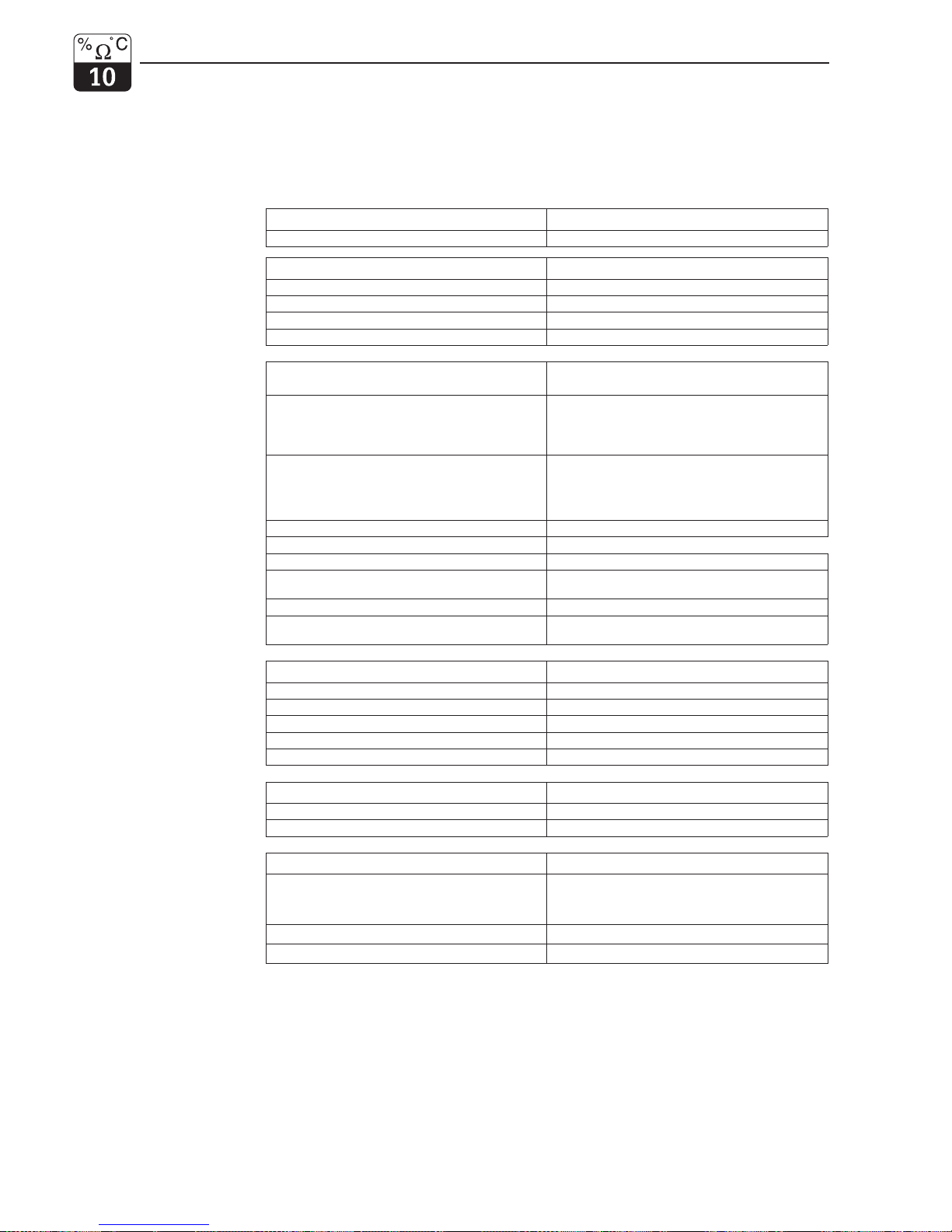
10 Technical data
MyPro CLM 431 conductive
General specifications
Manufacturer Endress+Hauser
Equipment designation MyPro CLM 431 conductive
Physical data
Dimensions (H × W × D) 227 × 104 × 137 mm
Weight max. 1.25 kg
Protection type IP 65
Housing material GD-AlSi 10 Mg, plastic-coated
Measured value display liquid crystal display
Conductivity/resistance
measurement
Measuring range
with cell constant k = 1
0 ... 600 mS/cm (uncompensated)
0...2MΩ⋅cm (uncompensated)
Conductivity measurement
Min. distance 4 ... 20 mA signal
with cell constant k = 1
meas. value 0 ... 199,9 µS/cm: 20 µS/cm
meas. value 200 ... 1999 µS/cm: 200 µS/cm
meas. value 2,000 ... 19,99 mS/cm: 2,000 mS/cm
meas. value > 20 mS/cm: 20 mS/cm
Resistance measurement
Min. distance 4 ... 20 mA signal
with cell constant k = 0,01
meas. value 0 ... 199,9 kΩ⋅cm: 25 kΩ⋅cm
meas. value 200 ... 1999 kΩ⋅cm: 0,25 MΩ⋅cm
meas. value 2,000 ... 19,99 MΩ⋅cm 2,5 MΩ⋅cm
meas. value > 20 MΩ⋅cm 25 MΩ⋅cm
Measurement deviation
1
(with CLS 12) ±0.5 % of measured value ± 4 digits
Reproducibility
1
(with CLS 12) ±0.1 % of measured value ± 2 digits
Usable cell constant k = 0.0025 ... 99.99 cm
–1
Max. sensor cable length conductivity
resistance
100 m
15 m
Max. resolution (in most sensitive measuring range) 10 nS/cm
Measuring frequency conductivity
resistance
299.75 ... 1077.6 Hz
32.5 ... 425 Hz
Temperature measurement
Temperature sensor connected Pt 100
Measuring range of Pt 100 –35 ... +250 °C
Measurement deviation
1
(entire measuring range) max. 0.5 % of MR
Measured value resolution 0.1 °C
Reproducibility
1
± 0.1 K
Adjustable temperature offset ±20 K
Temperature compensation
Compensation types linear, NaCl, ultrapure water, table
Range –35 ... +250 °C
Reference temperature adjustable; factory setting 25 °C
Signal output
Current range 4 ... 20 mA
Measurement deviation
1
± 22 µA ± 0,5 µA ⋅ I
real
/mA ⋅∆T/K
∆T=T
a
– 25 °C for Ta≥ 25 °C
∆T = 25 °C – T
a
for Ta< 25 °C
Load
max. 820 Ω
Resolution
< 6 µA
1
acc. to DIN IEC 60746 part 1, for nominal operating conditions
Technical data mypro CLM 431 / CLD 431 conductive
46 Endress+Hauser
Page 50
Electrical data
Supply voltage +12 ... +30 V DC
Power consumption max. 660 mW
Signal output 4 ... 20 mA, potential separated from sensor circuit
Error current signal output 22 mA ± 0.02 mA
HART
®
transfer: load
250 ... 820 Ω
HART
®
transfer: signal output 0.8 ... 1.2 mA (peak to peak)
Terminals, max. cable cross section 2.5 mm², screen 4 mm²
Vibration stability acc. to IEC 770
Mounting position pipeline
Vibration frequency 10 ... 60 Hz
Maximum amplitude 0.21 mm
Ambient conditions
Electromagnetic compatibility (EMC) Interference emission and interference immunity
acc. to EN 61326-1:1998
Ambient temperature T
a
(nominal operating conditions) –15 ... +55 °C
Relative humidity (nominal operating conditions) 10 ... 95 %, non-condensing
Ambient temperature T
a
(limit operating conditions) –20 ... +60 °C (Ex: –20 ... +55 °C)
Storage and transport temperature –20 ... +70 °C
Ex version of instrument
CLM 431-G
Intrinsically safe power supply and signal circuit, protection type EEx ib IIC T4
Max. input voltage
U
i
30 V DC
Max. input current
I
i
100 mA
Max. input power
P
i
750 mW
Max. internal inductance
L
i
200 µH
Max. internal capacitance
C
i
≈ 0, to PE = 5.3 nF
Intrinsically safe sensor circuit, protection type EEx ia IIC T4
Max. output voltage
U
o
± 5.4 ( 10.8) V DC
Max. output current
I
o
320 mA
Max. output power
P
o
200 mW
Max. external inductance
L
o
100 µH
Max. external capacitance
C
o
100 nF
CLM 431-H
Intrinsically safe power supply and signal circuit, protection type EEx ib IIC T4
Max. input voltage
U
i
30 V DC
Max. input current
I
i
100 mA
Max. input power
P
i
750 mW
Max. internal inductance
L
i
200 µH
Max. internal capacitance
C
i
≈ 0, to PE = 5.3 nF
Intrinsically safe sensor circuit, protection type EEx ia IIC T4
Max. output voltage
U
o
± 6.3 (12.6) V DC
Max. output current
I
o
130 mA
Max. output power
P
o
211 mW
Max. external inductance
L
o
100 µH
Max. external capacitance
C
o
100 nF
Supplementary documentation
TI CLS 12 order no. 50059349
TI CLS 13 order no. 50059350
TI CLS 15 order no. 50065950
TI CLS 19 order no. 50065951
TI CLS 21 order no. 50059352
mypro CLM 431 / CLD 431 conductive Technical data
Endress+Hauser 47
Page 51
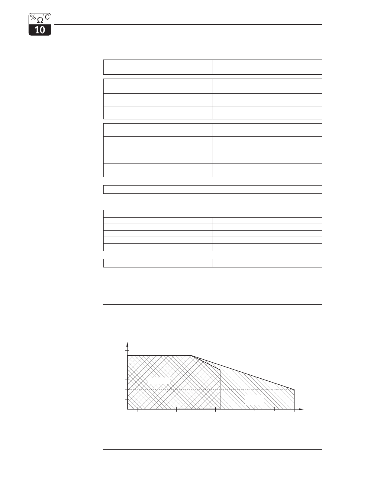
MyPro CLD 431 conductive
General specifications
Manufacturer Endress+Hauser
Equipment designation MyPro CLD 431 conductive
Physical data
Length with CLS 12 321 mm
Process connection G1 thread
Weight approx. 2 kg
Protection type IP 65
Housing material GD-AlSi 10 Mg, plastic-coated
Measured value display liquid crystal display
Conductivity/
resistance measurement
Measuring cell CLS 12
Conductivity measuring range version CA
version CB
0.04 ... 20 µS
0.1 ... 200 µS
Resistance measuring range version CA
version CB
0.05 ... 25 MΩ⋅cm
0.005 ... 10 MΩ⋅cm
Cell constant k = 0.01/cm in 0.04 ... 20 µS/cm measuring range
k = 0.1 /cm in 0.1 ... 200 µS/cm measuring range
Other data
Same as CLM 431 conductive
Ex version of instrument
CLD 431-H
Intrinsically safe power supply and signal circuit, protection type EEx ia/ib IIC T4
Max. input voltage
U
i
30 V
Max. input current
I
i
100 mA
Max. input power
P
i
750 mW
Max. internal inductance
L
i
200 µH
Max. internal capacitance
C
i
≈ 0, to PE = 5.3 nF
Supplementary documentation
TI CLS 12 order no. 50059349
Subject to modifications.
LM431CEX.CHP
60
80
100
120
140
16020
40
55
85
0
10
20
30
40
50
55
60
[° C]
[° C]
Ambient temperature
Ex area
Medium temperature
Non-Ex
area
TDIAGR.CDR
Fig. 10.1
Permissible temperature
ranges of MyPro CLD 431
Technical data mypro CLM 431 / CLD 431 conductive
48 Endress+Hauser
Page 52

11 Index
A
atable ............................. 32
Accessories . . . . . . . . . . . . . . . . . . . . . . . . . 45
Adjustment ranges. . . . . . . . . . . . . . . . . . . . 24
Alpha table. . . . . . . . . . . . . . . . . . . . . . . . . . 32
Angle bracket. . . . . . . . . . . . . . . . . . . . . . . . 11
B
Basic functions. . . . . . . . . . . . . . . . . . . . . . . 29
C
Ckey .............................. 21
Calibration . . . . . . . . . . . . . . . . . . . . . . . . . . 25
Calibration menu . . . . . . . . . . . . . . . . . . . . . 25
Calibration parameters . . . . . . . . . . . . . . . . 31
Calibration solution . . . . . . . . . . . . . . . . . . . 20
Cell constant . . . . . . . . . . . . . . . . . . 24-25, 46
Cleaning. . . . . . . . . . . . . . . . . . . . . . . . . . . . 44
Commubox. . . . . . . . . . . . . . . . . . . . . . . . . . 45
Commuwin . . . . . . . . . . . . . . . . . . . . . . . 40, 45
Commuwin operating matrix . . . . . . . . . . . . 41
Conductivity measuring cells. . . . . . . . . . . . 14
Conformity certificate. . . . . . . . . . . . . . . . . . . 6
Connection of CLS 12 . . . . . . . . . . . . . . . . . 15
Connection of CLS 19 . . . . . . . . . . . . . . . . . 15
Connection of conductivity measuring cells 14
Connection of MyPro in Ex area . . . . . . . . . 19
D
Damage . . . . . . . . . . . . . . . . . . . . . . . . . . . . . 2
Default values . . . . . . . . . . . . . . . . . 28-36, 42
Delivery, items included in. . . . . . . . . . . . . . . 2
Diagnosis . . . . . . . . . . . . . . . . . . . . . . . . . . . 33
Diagnostic code. . . . . . . . . . . . . . . . . . . 24, 42
Diagnostic parameter . . . . . . . . . . . . . . . . . 24
Dimensions . . . . . . . . . . . . . . . . . . . . . . . . . . 8
Display . . . . . . . . . . . . . . . . . . . . . . . . . . 13, 22
Display mode. . . . . . . . . . . . . . . . . . . . . . . . 23
Disposal . . . . . . . . . . . . . . . . . . . . . . . . . . . . . 2
E
Electrical connection . . . . . . . . . . . . . . . . . . 17
Electrical data . . . . . . . . . . . . . . . . . . . . . . . 47
Electromagnetic compatibility . . . . . . . . . . . 47
Error code . . . . . . . . . . . . . . . . . . . . . . . . . . 42
Error current . . . . . . . . . . . . . . . . . . . . . . . . . . 6
Error current assignment . . . . . . . . . . . . . . . 42
Error indication. . . . . . . . . . . . . . . . . . . . . . . 42
Error messages . . . . . . . . . . . . . . . . . . . . . . 24
Exareas............................ 19
Ex instrument version. . . . . . . . . . . . . . . 47-48
Examples for connection . . . . . . . . . . . . . . . 15
Extension cable CYK 71 . . . . . . . . . . . . 14, 45
F
Fkey............................ 21,26
Factorysettings...................... 20
Flange mounting . . . . . . . . . . . . . . . . . . . . . 11
Functional description . . . . . . . . . . . . . . 27-36
Functions........................... 21
G
General information . . . . . . . . . . . . . . . . . . 2-4
Generalsafetynotes....................5
Ground terminal . . . . . . . . . . . . . . . . . . . . . . 17
Grounding. . . . . . . . . . . . . . . . . . . . . . . . . . . 17
H
Hand-held HART terminal. . . . . . . . . 37-38, 45
HART Communicator . . . . . . . . . . . . . . . . . . 38
HART interface . . . . . . . . . . . . . . . . . . . . . . . 37
HART operating matrix . . . . . . . . . . . . . . . . . 39
Hazardous areas . . . . . . . . . . . . . . . . . . . . . . 6
Hazards. . . . . . . . . . . . . . . . . . . . . . . . . . . . . . 2
I
Immunity to interference. . . . . . . . . . . . . . 6, 17
Inquiries . . . . . . . . . . . . . . . . . . . . . . . . . . . . . 2
Installation....................... 5,7-19
Instructions for measuring cable connection 16
Instrument orientation . . . . . . . . . . . . . . . . . . 13
Intendeduse..........................5
Interfaces ..................... 21,37-41
Intrinsically safe power supply. . . . . 19, 47-48
Intrinsically safe sensor circuit . . . . . . . . . . . 19
J
JunctionboxVS ...................14,45
K
Keyactuation ........................21
Keyfunctions ........................21
Keypad . . . . . . . . . . . . . . . . . . . . . . . . . . 13, 21
Keys . . . . . . . . . . . . . . . . . . . . . . . . . . . . . . . 21
L
Lockingconcept......................22
M
Main parameters. . . . . . . . . . . . . . . . . . . . . . 27
Maintenance.........................44
Measuring cable connection . . . . . . . . . . . . 14
Measuring cable CYK 71 . . . . . . . . . . . . . . . 14
Measuringcell........................14
Measuringrange......................46
Measuring system. . . . . . . . . . . . . . . . . . . . . . 7
Monitoringfeatures.....................6
Mounting............................10
Mounting bracket . . . . . . . . . . . . . . . . . . 10-11
N
Nameplate. . . . . . . . . . . . . . . . . . . . . . . . . . 3-4
O
Operatingconcept....................21
Operatingelements ...................21
Operatinglevel1...................21,23
Operatinglevel2...................21,26
Operatingoptions.....................21
Operation ...................... 5,20-26
mypro CLM 431 / CLD 431 conductive Index
E+H Conducta 49
Page 53

INDEX-E.CHP
P
Packaging. . . . . . . . . . . . . . . . . . . . . . . . . . . . 2
Parameter settings . . . . . . . . . . . . . . . . . . . . 24
Physical data . . . . . . . . . . . . . . . . . . . . . . . . 46
Pipe mounting, DN 30 ... 200 . . . . . . . . . . . . 10
Pipe mounting, DN 60. . . . . . . . . . . . . . . . . . 10
Polarisation detection . . . . . . . . . . . . . . . . . . 33
Polarisation effects . . . . . . . . . . . . . . . . . . . . 33
Post mounting. . . . . . . . . . . . . . . . . . . . . . . . 17
Power supply . . . . . . . . . . . . . . . . . . . . . . . . 17
Power-up. . . . . . . . . . . . . . . . . . . . . . . . . . . . 20
Product structure . . . . . . . . . . . . . . . . . . . . . . 3
PROFIBUS interface . . . . . . . . . . . . . . . . . . . 41
Protection type, Ex . . . . . . . . . . . . . . . . . 47-48
Q
Questions . . . . . . . . . . . . . . . . . . . . . . . . . . . . 2
R
Repairs . . . . . . . . . . . . . . . . . . . . . . . . . . . 5, 44
Resistance . . . . . . . . . . . . . . . . . . . . . . . . . . 18
S
Safety . . . . . . . . . . . . . . . . . . . . . . . . . . . . . 5-6
Safety features . . . . . . . . . . . . . . . . . . . . . . . . 6
Secondary parameter. . . . . . . . . . . . . . . . . . 23
Secondary parameter menu. . . . . . . . . . . . . 23
Service . . . . . . . . . . . . . . . . . . . . . . . . . . 35, 44
Signal output . . . . . . . . . . . . . . . . . . . . . . . . 46
Simulation . . . . . . . . . . . . . . . . . . . . . . . . . . 35
Start-up .......................... 5,20
Storage. . . . . . . . . . . . . . . . . . . . . . . . . . . . . . 2
Symbols . . . . . . . . . . . . . . . . . . . . . . . . . . . . . 2
T
Technicaldata.....................46-48
Temperature coefficient. . . . . . . . . . . . . . 24-25
Temperature compensation . . . . . . . . . 25, 46
Temperature measurement. . . . . . . . . . . . . 46
Temperature sensor . . . . . . . . . . . . . . . . 7, 46
Terminal block . . . . . . . . . . . . . . . . . . . . . . . 16
Terminals . . . . . . . . . . . . . . . . . . . . . . . . . 16-17
Transmitter power supply units . . . . . . . . . . 45
Transport . . . . . . . . . . . . . . . . . . . . . . . . . . . . 2
Troubleshooting. . . . . . . . . . . . . . . . . 5, 42-43
Two-wire line . . . . . . . . . . . . . . . . . . . . . . . . 17
U
Uncompensated conductivity . . . . . . . . . . . 25
Unpacking . . . . . . . . . . . . . . . . . . . . . . . . . . . 2
Use................................. 5
Userinfo............................ 36
W
Wallmounting ....................... 11
Write protection . . . . . . . . . . . . . . . . . . . . . . 22
Index mypro CLM 431 / CLD 431 conductive
50 E+H Conducta
Page 54

Europe
Austria
❑ Endress+Hauser Ges.m.b.H.
Wien
Tel. ++43 (1) 88056-0, Fax (1) 88056-35
Belarus
Belorgsintez
Minsk
Tel. ++375(172) 263166, Fax (1 72) 263111
Belgium / Luxembourg
❑ Endress+Hauser S.A./N.V.
Brussels
Tel. ++32 (2) 2480600, Fax (2) 2480553
Bulgaria
INTERTECH-AUTOMATION
Sofia
Tel. ++359(2)664869, Fax (2) 9631389
Croatia
❑ Endress+Hauser GmbH+Co.
Zagreb
Tel. ++385(1)6637785, Fax (1) 66378 23
Cyprus
I+G Electrical Services Co.Ltd.
Nicosia
Tel. ++357(2) 484788, Fax (2) 484690
Czech Republic
❑ Endress+Hauser GmbH+Co.
Praha
Tel. ++420(26)6784200,Fax (26) 67841 79
Denmark
❑ Endress+Hauser A/S
Søborg
Tel. ++45 (70) 131132, Fax (70) 132133
Estonia
Elvi-Aqua
Tartu
Tel. ++372(7) 422726, Fax (7) 422727
Finland
❑ Endress+Hauser Oy
Espoo
Tel. ++358(9)8596155, Fax (9) 85960 55
France
❑ Endress+Hauser
Huningue
Tel. ++33 (3) 89696768, Fax (3) 89 694802
Germany
❑ Endress+Hauser Meßtechnik GmbH+Co.
Weil am Rhein
Tel. ++49 (7621) 97501, Fax (76 21) 9755 55
Great Britain
❑ Endress+Hauser Ltd.
Manchester
Tel. ++44 (161) 2865000,
Fax(161)9981841
Greece
I & G Building ServicesAutomationS.A.
Athens
Tel. ++30 (1) 9241500, Fax (1) 9221714
Hungary
Mile Ipari-Elektro
Budapest
Tel. ++36 (1) 2615535, Fax (1) 2615535
Iceland
VatnshreinsunHF
Reykjavik
Tel. ++354(5) 619616, Fax (5) 619617
Ireland
Flomeaco Company Ltd.
Kildare
Tel. ++353(45) 868615, Fax (45) 868182
Italy
❑ Endress+Hauser Italia S.p.A.
Cernusco s/N Milano
Tel. ++39 (02) 92106421,
Fax (02) 921071 53
Latvia
Raita Ltd.
Riga
Tel. ++371(7) 312897, Fax (7) 312894
Lithuania
Agava Ltd.
Kaunas
Tel. ++370(7) 202410, Fax (7) 207414
Netherlands
❑ Endress+Hauser B.V.
Naarden
Tel. ++31 (35) 6958611, Fax (35) 69588 25
Norway
❑ Endress+Hauser A/S
Tranby
Tel. ++47 (32) 859850, Fax (32) 859851
Poland
❑ Endress+Hauser Polska Sp.zo.o.
Warszawy
Tel. ++48 (22) 72010 90, Fax (22) 7 201085
Portugal
Tecnisis - Tecnica de Sistemas Industriais
Linda-a-Velha
Tel. ++351(1)4172637, Fax (1) 41852 78
Romania
Romconseng SRL
Bucharest
Tel. ++40 (1) 4101634, Fax (1) 4101634
Russia
❑ Endress+Hauser Moscow Office
Moscow
Tel.++709(5) 1587571, Fax (5) 15898 64
Slovak Republic
Transcom Techniks.r.o.
Bratislava
Tel. ++421(74)4888684,Fax (74) 48871 12
Slovenia
❑ Endress+Hauser D.O.O.
Ljubljana
Tel. ++386(61)1592217,Fax (61) 15922 98
Spain
❑ Endress+Hauser S.A.
Barcelona
Tel. ++34 (93) 48033 66, Fax (93) 4 733839
Sweden
❑ Endress+Hauser AB
Sollentuna
Tel. ++46 (8) 55 511600, Fax (8) 55511600
Switzerland
❑ Endress+Hauser AG
Reinach/BL 1
Tel. ++41 (61) 71575 75, Fax (61) 7 111650
Turkey
Intek Endüstriyel Ölcü ve Kontrol Sistemleri
Istanbul
Tel. ++90 (212)2751355,
Fax(212) 2662775
Ukraine
Industria Ukraïna
Kiev
Tel. ++380(44)26881, Fax (44) 2 6908
Yugoslavia
Meris d.o.o.
Beograd
Tel. ++381(11)4446164,Fax (11) 44419 66
Africa
Egypt
Anasia
Heliopolis/Cairo
Tel. ++20 (2) 417900, Fax (2) 417900
Morocco
Oussama S.A.
Casablanca
Tel. ++212(2)241338, Fax (2) 402657
Nigeria
J F TechnicalInvest.Nig. Ltd.
Lagos
Tel. ++234(1) 62234546, Fax (1) 622345 48
South Africa
❑ Endress+Hauser Pty. Ltd.
Sandton
Tel. ++27 (11) 44413 86, Fax (11) 4 441977
Tunisia
Controle, Maintenance et Regulation
Tunis
Tel. ++216(1)793077, Fax (1) 788595
America
Argentina
❑ Endress+Hauser Argentina S.A.
Buenos Aires
Tel. ++54 (1) 145227970,
Fax(1) 145227909
Bolivia
Tritec S.R.L.
Cochabamba
Tel. ++591(42)56993, Fax (42) 5 0981
Brazil
❑ Samson Endress+Hauser Ltda.
Sao Paulo
Tel.++55 (11) 50313455,
Fax (11) 5031 3067
Canada
❑ Endress+Hauser Ltd.
Burlington, Ontario
Tel.++1 (905) 6819292,
Fax(905)6819444
Chile
DIN Instrumentos Ltda.
Santiago
Tel.++56 (2) 2050100, Fax (2) 22581 39
Colombia
Colsein Ltd.
Bogota D.C.
Tel.++57 (1) 2367659, Fax (1) 61078 68
Costa Rica
EURO-TEC S.A.
San Jose
Tel.++506(2) 961542, Fax ( 2) 961542
Ecuador
Insetec Cia. Ltda.
Quito
Tel.++593(2)269148, Fax (02) 46 1833
Guatemala
ACISA Automatizacion Y Control Industrial S.A.
Ciudad de Guatemala, C.A.
Tel.++502(3) 345985, Fax (2) 327431
Mexico
❑ Endress+Hauser I.I.
Mexico City
Tel.++52 (5) 568965, Fax (5) 568418
Paraguay
Incoel S.R.L.
Asuncion
Tel.++595(21) 213989, Fax (21) 226583
Uruguay
Circular S.A.
Montevideo
Tel.++598(2) 925785, Fax (2) 929151
USA
❑ Endress+Hauser Inc.
Greenwood, Indiana
Tel.++1 (317) 5357138,
Fax(317)5358489
Venezuela
H.Z.InstrumentosC.A.
Caracas
Tel.++58 (2) 9440966, Fax (2) 94445 54
Asia
China
❑ Endress+Hauser Shanghai
Instrumentation Co.Ltd.
Shanghai
Tel.++86 (21) 54902300,
Fax (21) 549023 03
❑ Endress+Hauser Beijing Office
Beijing
Tel.++86 (10) 68344058,
Fax (10) 683440 68
❑ Endress+Hauser (H.K.) Ltd.
Hong Kong
Tel.++852(2)5283120, Fax (2) 86541 71
India
❑ Endress+Hauser India Branch Office
Mumbai
Tel.++91 (22) 8521458, Fax (22) 85219 27
Indonesia
PT Grama Bazita
Jakarta
Tel.++62 (21) 7975083, Fax (21) 79750 89
Japan
❑ Sakura Endress Co., Ltd.
Tokyo
Tel.++81 (422) 540611, Fax (4 22) 550275
Malaysia
❑ Endress+Hauser (M) Sdn. Bhd.
PetalingJaya,SelangorDarul Ehsan
Tel.++60 (3) 7334848, Fax (3) 73388 00
Pakistan
Speedy Automation
Karachi
Tel.++92 (21) 7722953, Fax (21) 77368 84
Papua New Guinea
SBS Electrical Pty Limited
Port Moresby
Tel.++675 (3) 251188, Fax (3) 259556
Philippines
Brenton Industries Inc.
Makati Metro Manila
Tel.++63 (2) 6388041, Fax (2) 63880 42
Singapore
❑ Endress+Hauser (S.E.A.)Pte., Ltd.
Singapore
Tel.++65 (5) 66 8222,Fax(2) 666848
South Korea
❑ Endress+Hauser (Korea)Co.,Ltd.
Seoul
Tel.++82 (2) 6587200, Fax (2) 65928 38
Taiwan
Kingjarl Corporation
Taipei R.O.C.
Tel.++886 (2) 27183938, Fax (2) 27134190
Thailand
❑ Endress+Hauser Ltd.
Bangkok
Tel.66 (2) 996781120,Fax (2) 99678 10
Vietnam
Tan Viet Bao Co. Ltd.
Ho Chi Minh City
Tel.++84 (8) 8335225, Fax (8) 83352 27
Iran
Telephone TechnicalServicesCo.Ltd.
Tehran
Tel.++98 (21) 8746750, Fax (21) 87372 95
Israel
Instrumetrics Industrial ControlLtd.
Tel-Aviv
Tel.++972 (3) 6480205, Fax (3) 6471992
Jordan
A.P. Parpas Engineering S.A.
Amman
Tel.++962 (6) 4643246, Fax (6) 4645707
Kingdom of Saudi Arabia
Anasia
Jeddah
Tel.++966 (2) 6710014, Fax (2) 6725929
Kuwait
Kuwait Maritime & Mercantile Co.K.S.C.
Safat
Tel.++965(2) 441481, Fax (2) 441486
Lebanon
Nabil Ibrahim
Jbeil
Tel.++961 (3) 254052, Fax (9) 548038
Sultanate of Oman
Mustafa& Jawad Science & Industry Co.
L.L.C.
Ruwi
Tel.++968 (60) 2009,Fax(60) 7066
United Arab Emirates
Descon Trading EST.
Dubai
Tel.++971 (4) 653651, Fax (4) 653264
Yemen
Yemen Company for Ghee and Soap Industry
Taiz
Tel.++976 (4) 230664, Fax (4) 212338
Australia + New Zealand
Australia
ALSTOM Australia Ltd.
Sydney
Tel.++61 (2) 97224777, Fax (2) 97224888
New Zealand
EMC Industrial Instrumentation
Auckland
Tel.++64 (9) 4155110, Fax (9) 41551 15
All other countries
❑ Endress+Hauser GmbH+Co.
Instruments International
D-Weil am Rhein
Germany
Tel.++49 (7621) 97502, Fax (7 621)9753 45
BA 202C/07/en/02.00
Printed in Germany / CV5 / Lf
❑ Members of the Endress+Hauser group
Endress Hauser
The Power of Know How
51500561
 Loading...