

Page 1
TI01118T/09/EN/02.19
71443145
2019-06-05
Products
Solutions Services
Technical Information
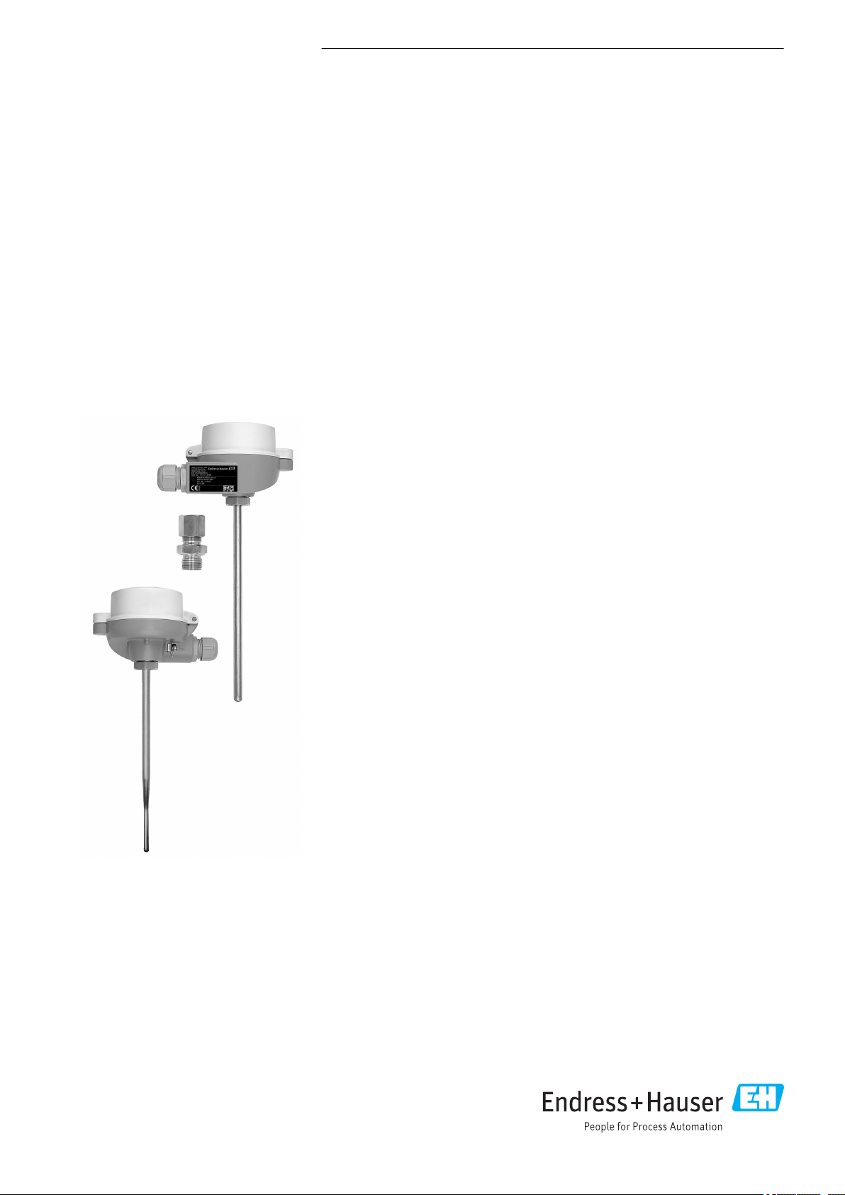
Omnigrad M TR12, TC12
Modular thermometer
TR12 with resistance insert (RTD)
TC12 with thermocouple insert (TC)
with thermowell and compression fitting
Application
• Universal range of application
• Measuring range:
• Resistance insert (RTD): –200 to 600 °C (–328 to 1 112 °F)
• Thermocouple (TC): –40 to 1 100 °C (–40 to 2 012 °F)
• Pressure range up to 40 bar (580 psi)
• Degree of protection up to IP68
Head transmitter
All Endress+Hauser transmitters are available with enhanced accuracy and reliability
compared to directly wired sensors. Easy customizing by choosing one of the
following outputs and communication protocols:
• Analog output 4 to 20 mA
• HART
• PROFIBUS® PA
• FOUNDATION Fieldbus™
Your benefits
• High degree of flexibility thanks to modular design with standard terminal heads
• High degree of compatibility and design as per DIN 43772
• Fast response time with reduced/tapered tip form
• Types of protection for use in hazardous locations:
®
as per DIN EN 50446 and customer-specific immersion lengths
• Intrinsic Safety (Ex ia)
• Non-sparking (Ex nA)
Page 2

Function and system design
Measuring principle Resistance thermometer (RTD)
These resistance thermometers use a Pt100 temperature sensor according to IEC 60751. The
temperature sensor is a temperature-sensitive platinum resistor with a resistance of 100 Ω at
0 °C (32 °F) and a temperature coefficient α = 0.003851 °C-1.
There are generally two different kinds of platinum resistance thermometers:
• Wire wound (WW): Here, a double coil of fine, high-purity platinum wire is located in a ceramic
support. This is then sealed top and bottom with a ceramic protective layer. Such resistance
thermometers not only facilitate very reproducible measurements but also offer good long-term
stability of the resistance/temperature characteristic within temperature ranges up to
600 °C (1 112 °F). This type of sensor is relatively large in size and it is comparatively sensitive to
vibrations.
• Thin film platinum resistance thermometers (TF): A very thin, ultrapure platinum layer,
approx. 1 μm thick, is vaporized in a vacuum on a ceramic substrate and then structured
photolithographically. The platinum conductor paths formed in this way create the measuring
resistance. Additional covering and passivation layers are applied and reliably protect the thin
platinum layer from contamination and oxidation, even at high temperatures.
The primary advantages of thin film temperature sensors over wire wound versions are their smaller
sizes and better vibration resistance. A relatively low principle-based deviation of the resistance/
temperature characteristic from the standard characteristic of IEC 60751 can frequently be observed
among TF sensors at high temperatures. As a result, the tight limit values of tolerance category A as
per IEC 60751 can only be observed with TF sensors at temperatures up to approx. 300 °C (572 °F).
Omnigrad M TR12, TC12
Thermocouples (TC)
Thermocouples are comparatively simple, robust temperature sensors which use the Seebeck effect
for temperature measurement: if two electrical conductors made of different materials are connected
at a point, a weak electrical voltage can be measured between the two open conductor ends if the
conductors are subjected to a thermal gradient. This voltage is called thermoelectric voltage or
electromotive force (emf.). Its magnitude depends on the type of conducting materials and the
temperature difference between the "measuring point" (the junction of the two conductors) and the
"cold junction" (the open conductor ends). Accordingly, thermocouples primarily only measure
differences in temperature. The absolute temperature at the measuring point can be determined
from these if the associated temperature at the cold junction is known or is measured separately and
compensated for. The material combinations and associated thermoelectric voltage/temperature
characteristics of the most common types of thermocouple are standardized in the IEC 60584 and
ASTM E230/ANSI MC96.1 standards.
2 Endress+Hauser
Page 3
Omnigrad M TR12, TC12
A
= 20-250V DC/AC
» 50/60Hz
4...20 mA
24V DC / 30 mA
B
C
°C
1 2
3
4
5
66a 6b
IL
IL
L
35
(1.38)
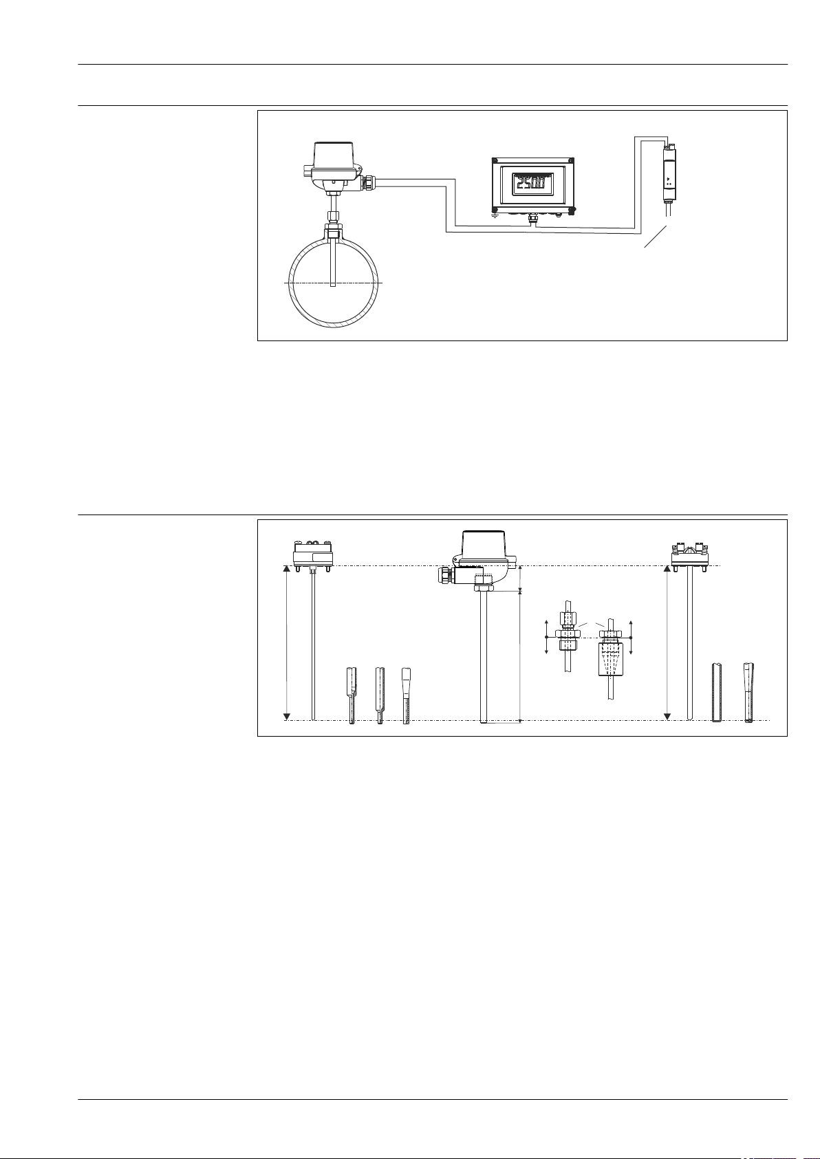
Measuring system
A0009647
1 Application example
A Thermometer with built-in head transmitter
B RIA16 field display unit - The display unit records the analog measuring signal from the head transmitter and
shows this on the display. The LC display shows the current measured value in digital form and as a bar graph
indicating a limit value violation. The display unit is looped into the 4 to 20 mA circuit and gets the required
energy from there. More information on this can be found in the Technical Information (see "Documentation").
C Active barrier RN221N - The RN221N active barrier (24 V DC, 30 mA) has a galvanically isolated output for
powering 2-wire transmitters. The universal power supply works with an input supply voltage of 20 to 250 V
DC/AC, 50/60 Hz, which means that it can be used in all international power grids. More information on this
can be found in the Technical Information (see "Documentation").
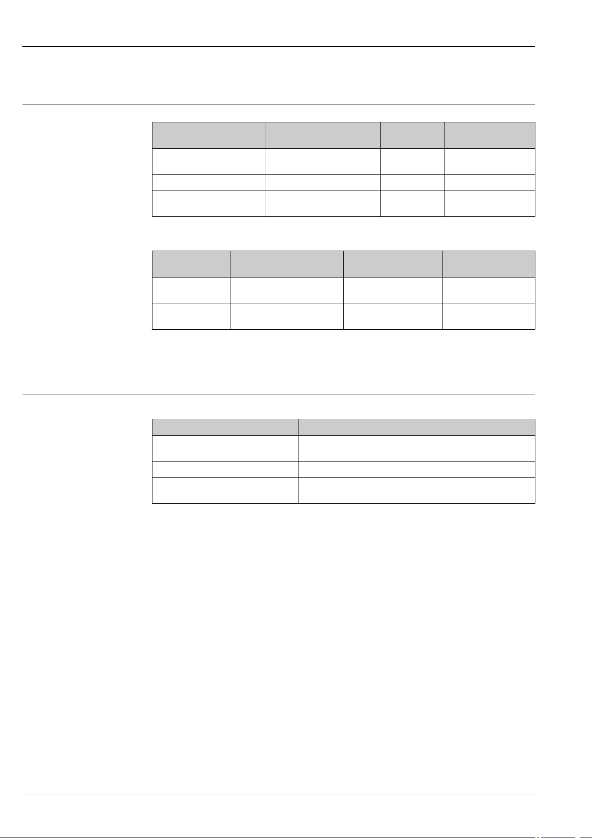
Design
A0009648
2 Thermometer design
1 Insert with mounted head transmitter (example with 3 mm (0.12 in))
2 Insert with mounted ceramic terminal block (example with 6 mm (0.24 in))
3 Terminal head
4 Protective assembly
5 Process connection: compression fittings TA50, TA70
6 Various tip shapes - for detailed information see "Shape of tip" section:
6a Reduced or tapered tip for inserts with 3 mm (0.12 in)
6b Straight or tapered tip for inserts with 6 mm (0.24 in)
L Immersion length
IL Insertion length = L + 35 mm (1.38 in)
Thermometers from the Omnigrad M TR12 and TC12 series have a modular design. The terminal
head is used as a connection module for the mechanical and electrical connection of the insert. The
position of the actual thermometer sensor in the insert ensures that it is mechanically protected. The
insert can be replaced or calibrated without interrupting the process. Either ceramic terminal blocks
or transmitters can be fitted to the internal terminal block. The thermometer can be mounted on a
pipe or tank using a compression fitting. The most commonly used compression fittings are available
for installation → 19.
Endress+Hauser 3
Page 4
Input
Omnigrad M TR12, TC12
Measuring range
RTD resistance thermometers
Sensor type Measuring range Connection type Temperature-sensitive
length
Pt100 (IEC 60751, TF)
iTHERM StrongSens
Pt100 thin-film sensor (TF) –50 to 400 °C (–58 to 752 °F) 3- or 4-wire 10 mm (0.39 in)
Pt100 wire-wound sensor
(WW)
–50 to +500 °C
(–58 to +932 °F)
–200 to 600 °C
(–328 to 1 112 °F)
3- or 4-wire 7 mm (0.27 in)
3- or 4-wire 10 mm (0.39 in)
TC thermocouples:
Sensor type Measuring range Connection type Temperature-sensitive
length
Thermocouple type K –40 to +1 100 °C
(–40 to +2 012 °F)
Thermocouple type J –40 to +750 °C
(–40 to +1 382 °F)
Grounded or insulated
connection
Grounded or insulated
connection
Insert length
Insert length
Performance characteristics
Operating conditions Ambient temperature range
Terminal head Temperature in °C (°F)
Without mounted head transmitter
With mounted head transmitter –40 to 85 °C (–40 to 185 °F)
With mounted head transmitter and
display
Process pressure
The maximum process pressure depends on the process connection used. See the "Process
connection" section for an overview of the process connections that can be used→ 19.
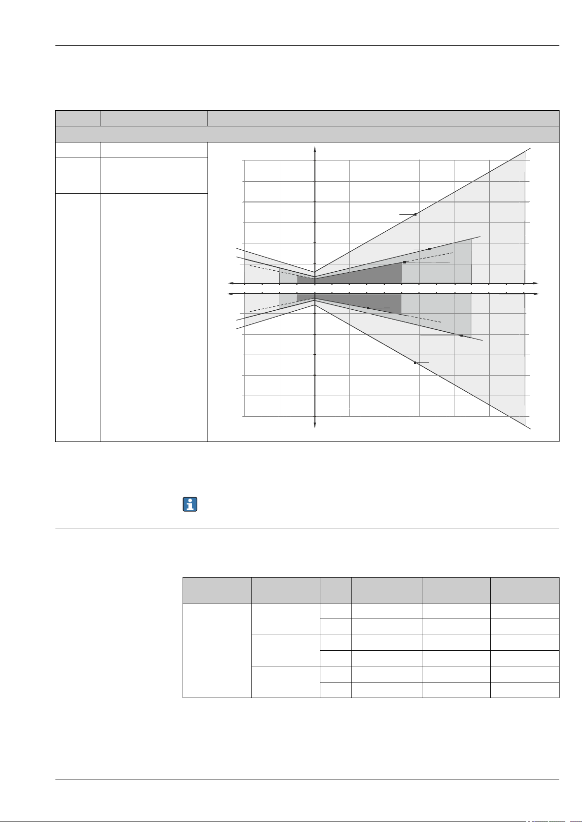
Maximum flow velocity
The maximum flow velocity tolerated by the thermowell diminishes with increasing immersion of
the sensor in the liquid flow. See the figures below for more detailed information.
Depends on the terminal head used and the cable gland or fieldbus
connector, see 'Terminal heads' section
–20 to 70 °C (–4 to 158 °F)
4 Endress+Hauser
Page 5

Omnigrad M TR12, TC12
100 200 300 400 500
v (m/s)
A
100 200 300 400 500
v (m/s)
B
4
8
12 16 20
4
8
12 16
v (ft/s)
v (ft/s)
L (mm)
0
10
20
30
40
50
60
70
80
90
L (in)
20
0
30
65
100
130
165
200
230
260
295
0
5
10
15
20
25
30
35
40
45
0
15
30
50
65
80
100
115
130
145
L (mm)
L (in)
50
2
50
2
A0008605
3 Flow velocity depending on the immersion depth
A Medium water at T = 50 °C (122 °F)
B Medium superheated steam at T = 400 °C (752 °F)
L Immersion length
v Flow velocity
___ Thermowell diameter 9 x 1 mm (0.35 in)
- - - Thermowell diameter 12 x 2.5 mm (0.47 in)
Endress+Hauser 5
Page 6
Omnigrad M TR12, TC12
Shock and vibration resistance
The Endress+Hauser inserts meet the requirements of IEC 60751, which specify shock and vibration
resistance of 3g in the range from 10 to 500 Hz.
The vibration resistance at the measuring point depends on the sensor type and design, see the
following table:
Version Vibration resistance for the sensor tip
Pt100 (WW or TF) 30 m/s2 (3g)
iTHERM® StrongSens Pt100 (TF)
> 600 m/s2 (60g) for sensor tip
iTHERM® QuickSens Pt100 (TF), version: 6 mm (0.24 in)
1) vibration resistance also applies to the quick-fastening iTHERM QuickNeck
1)
Accuracy
Permissible deviation limits of thermoelectric voltages from the standard characteristic for
thermocouples as per IEC 60584 or ASTM E230/ANSI MC96.1:
Standard Type Standard tolerance Special tolerance
IEC 60584 Class Deviation Class Deviation
J (Fe-CuNi) 2 ±2,5 °C (–40 to 333 °C)
±0,0075 |t|
K (NiCr-NiAl) 2 ±2,5 °C (–40 to 333 °C)
±0,0075 |t|
1)
(333 to 750 °C)
1)
(333 to 1 200 °C)
1) |t| = absolute value in °C
Standard Type Standard tolerance Special tolerance
ASTM E230/ANSI
MC96.1
J (Fe-CuNi) ±2,2 K or ±0,0075 |t|
K (NiCrNiAl)
Deviation, the larger respective value applies
1)
(0 to 760 °C) ±1,1 K or ±0,004 |t|
±2,2 K oder ±0,02 |t|
±2,2 K or ±0,0075 |t|
1)
(–200 to 0 °C)
1)
(0 to 1 260 °C)
1) |t| = absolute value in °C
1 ±1,5 °C (–40 to 375 °C)
±0,004 |t|
1 ±1,5 °C (–40 to 375 °C)
±0,004 |t|
1)
(375 to 750 °C)
1)
(375 to 1 000 °C)
(0 to 760 °C)
±1,1 K or ±0,004 |t|
(0 to 1 260 °C)
1)
1)
6 Endress+Hauser
Page 7
Omnigrad M TR12, TC12
A
AA
-200 -100 0 100 200 300 400 500 600°C
0.5
1.0
1.5
2.0
B
2.5
3.0
- 0.5
- 1.0
- 1.5
- 2.0
- 2.5
- 3.0
B
A
AA
Max. deviation (°C)
Max. deviation (°C)
RTD resistance thermometer as per IEC 60751
Class max. tolerances (°C) Characteristics
RTD maximal error Type TF
Cl. A ± (0,15 + 0,002 · |t|
Cl. AA,
± (0,1 + 0,0017 · |t|)
former 1/3
Kl. B
Cl. B ± (0,3 + 0,005 · |t|)
1)
)
1) |t| = absolute value in °C
In order to obtain the maximum tolerances in °F, the results in °C must be multiplied by a factor
of 1.8.
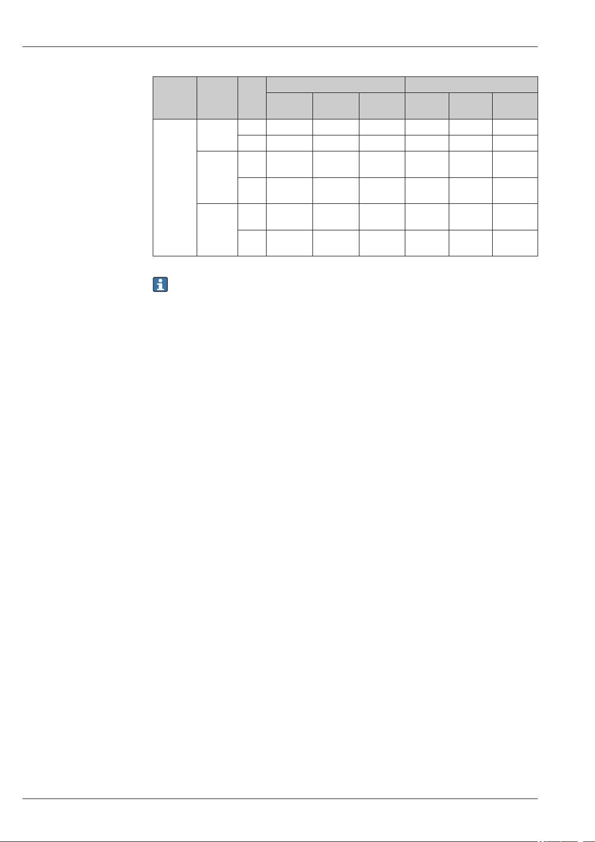
Response time
Calculated at an ambient temperature of approx. 23 °C by immersing in running water (0.4 m/s flow
rate, 10 K excess temperature):
Complete design:
Thermometer
type
Resistance
thermometer
(measuring probe
Pt100, TF/WW)
Diameter t
9 mm (0.35 in) t
11 mm (0.43 in) t
12 mm (0.47 in) t
A0008588-EN
Reduced tip Tapered tip Straight tip
(x)
7.5 s 11 s 18 s
50
t
t
t
21 s 37 s 55 s
90
7.5 s not available 18 s
50
21 s not available 55 s
90
not available 11 s 38 s
50
not available 37 s 125 s
90
Endress+Hauser 7
Page 8
Omnigrad M TR12, TC12
Thermom
eter type
Diameter t
(x)
Reduced
tip
Thermoco
uple
9 mm
(0.35 in)
11 mm
t
5.5 s 9 s 15 s 6 s 9.5 s 16 s
50
t
13 s 31 s 46 s 14 s 33 s 49 s
90
t
5.5 s not
50
(0.43 in)
t
13 s not
90
12 mm
(0.47 in)
t
not
50
available
t
not
90
available
Response time for insert without transmitter.
Grounded Not grounded
Tapered
tip
Straight
tip
Reduced
tip
Tapered
tip
15 s 6 s not
available
available
46 s 14 s not
available
8.5 s 32 s not
available
9 s 34 s
available
20 s 106 s not
22 s 110 s
available
Straight
tip
16 s
49 s
8 Endress+Hauser
Page 9
Omnigrad M TR12, TC12
Tested in accordance with IEC 60751 in flowing water (0.4 m/s at 30 °C):
Insert:
Sensor type Diameter ID Response time
iTHERM® StrongSens 6 mm (0.24 in) t
3 mm (0.12 in) t
TF sensor
6 mm (0.24 in) t
3 mm (0.12 in) t
WW sensor
6 mm (0.24 in) t
3 mm (0.12 in) t
Thermocouple (TPC100)
Grounded
6 mm (0.24 in) t
3 mm (0.12 in) t
Thermocouple (TPC100)
Not grounded
6 mm (0.24 in) t
50
t
90
50
t
90
50
t
90
50
t
90
50
t
90
50
t
90
50
t
90
50
t
90
50
t
90
< 3.5 s
< 10 s
2.5 s
5.5 s
5 s
13 s
2 s
6 s
4 s
12 s
0.8 s
2 s
2 s
5 s
1 s
2.5 s
2.5 s
7 s
Insulation resistance
Self heating
Calibration
Response time for sensor design without transmitter.
• RTD:
Insulation resistance according to IEC 60751 > 100 MΩ at 25 °C between terminals and sheath
material measured with a minimum test voltage of 100 V DC
• TC:
Insulation resistance according to IEC 1515 between terminals and sheath material with a test
voltage of 500 V DC:
• > 1 GΩ at 20 °C
• > 5 MΩ at 500 °C
RTD elements are passive resistances that are measured using an external current. This
measurement current causes a self-heating effect in the RTD element itself which in turn creates an
additional measurement error. In addition to the measurement current, the size of the measurement
error is also affected by the temperature conductivity and flow velocity of the process. This selfheating error is negligible when an Endress+Hauser iTEMP temperature transmitter (very small
measurement current) is connected.
Endress+Hauser provides comparison temperature calibration from
–80 to +1 400 °C (–110 to +2 552 °F) based on the International Temperature Scale (ITS90).
Endress+Hauser 9
Page 10

Omnigrad M TR12, TC12
Calibrations are traceable to national and international standards. The calibration certificate is
referenced to the serial number of the thermometer. Only the insert is calibrated.
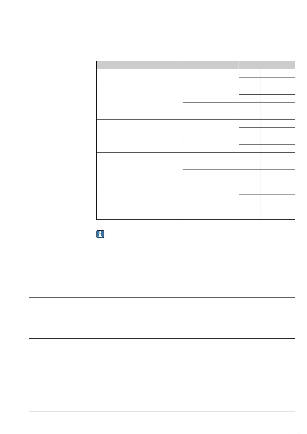
Material
Insert:
⌀6 mm (0.24 in) and 3 mm (0.12 in)
Temperature range without head transmitter with head transmitter
–80 to 250 °C (–110 to 480 °F) No minimum immersion length required
250 to 550 °C (480 to 1 020 °F) 300 (11.81)
550 to 1 400 °C (1 020 to 2 552 °F) 450 (17.72)
Minimum insertion length of insert in mm (in)
Thermowell, process connection and insert.
The temperatures for continuous operation specified in the following table are only intended as
reference values for use of the various materials in air and without any significant compressive load.
The maximum operating temperatures are reduced considerably in some cases where abnormal
conditions such as high mechanical loads occur, or in aggressive media.
Designation Short form Recommended
max.
temperature for
continuous use
in air
AISI 316L/
1.4404
1.4435
AISI 316Ti/
1.4571
AISI 310/
1.4841
AISI 316/
1.4401
X2CrNiMo17-12-2
X2CrNiMo18-14-3
X6CrNiMoTi17-12-2 700 °C
X15CrNiSi25-20 1 100 °C
X5CrNiMo17-12-2 650 °C
650 °C
(1 202 °F)
(1 292 °F)
(2 012 °F)
(1 202 °F)
1)
1)
1)
Properties
• Austenitic, stainless steel
• High corrosion resistance in general
• Particularly high corrosion-resistance in
chlorine-based and acidic, non-oxidizing
atmospheres through the addition of
molybdenum (e.g. phosphoric and sulfuric
acids, acetic and tartaric acids with a low
concentration)
• Increased resistance to intergranular corrosion
and pitting
• Compared to 1.4404, 1.4435 has even higher
corrosion resistance and a lower delta ferrite
content
• Properties comparable with AISI316L
• The addition of titanium increases resistance to
intergranular corrosion even after welding
• Broad range of uses in the chemical,
petrochemical and oil industries as well as in
coal chemistry
• Can only be polished to a limited extent,
titanium streaks can form
• Austenitic, stainless steel
• Generally well resistant to oxidizing and
reducing atmospheres
• Due to the higher chromium content, well
resistant to oxidizing aqueous solutions and
neutral salts melting at higher temperatures
• Low resistance to sulfur-containing gases
• Austenitic, stainless steel
• High corrosion resistance in general
• Particularly high corrosion-resistance in
chlorine-based and acidic, non-oxidizing
atmospheres through the addition of
molybdenum (e.g. phosphoric and sulfuric
acids, acetic and tartaric acids with a low
concentration)
10 Endress+Hauser
Page 11

Omnigrad M TR12, TC12
Designation Short form Recommended
max.
temperature for
continuous use
in air
Inconel600/
2.4816
Hastelloy
C276/ 2.4819
PTFE (Teflon) Polytetrafluorethylene 200 °C (392 °F) • Resistance to almost all chemicals
1) Can be used to a limited extent up to 800 °C (1472 °F) for low compressive loads and in non-corrosive
media. Please contact your Endress+Hauser sales team for further information.
NiCr15Fe 1 100 °C
(2 012 °F)
NiMo16Cr15W 1 100 °C
(2 012 °F)
Properties
• A nickel/chromium alloy with very good
resistance to aggressive, oxidizing and reducing
atmospheres, even at high temperatures
• Resistance to corrosion caused by chlorine
gases and chlorinated media as well as many
oxidizing mineral and organic acids, sea water
etc.
• Corrosion from ultrapure water
• Not to be used in sulfur-containing
atmospheres
• Nickel-based alloy with very good resistance to
oxidizing and reducing atmospheres, even at
high temperatures
• Particularly resistant to chlorine gas and
chlorides as well as many oxidizing mineral and
organic acids
• High temperature-resistance
Endress+Hauser 11
Page 12

Components
Omnigrad M TR12, TC12
Family of temperature transmitters
Thermometers fitted with iTEMP transmitters are an installation-ready complete solution to
improve temperature measurement by significantly increasing accuracy and reliability, when
compared to direct wired sensors, as well as reducing both wiring and maintenance costs.
4 to 20 mA head transmitters
They offer a high degree of flexibility, thereby supporting universal application with low inventory
storage. The iTEMP transmitters can be configured quickly and easily at a PC. Endress+Hauser offers
free configuration software which can be downloaded from the Endress+Hauser Website. More
information can be found in the Technical Information.
HART® head transmitters
The transmitter is a 2-wire device with one or two measuring inputs and one analog output. The
device not only transfers converted signals from resistance thermometers and thermocouples, it also
transfers resistance and voltage signals using HART® communication. Swift and easy operation,
visualization and maintenance using universal device configuration tools like FieldCare, DeviceCare
or FieldCommunicator 375/475. Integrated Bluetooth® interface for the wireless display of
measured values and configuration via E+H SmartBlue (app), optional. For more information, see the
Technical Information.
PROFIBUS® PA head transmitters
Universally programmable head transmitter with PROFIBUS® PA communication. Conversion of
various input signals into digital output signals. High accuracy over the complete ambient
temperature range. The configuration of PROFIBUS PA functions and of device-specific parameters is
performed via fieldbus communication. For more information, see the Technical Information.
FOUNDATION Fieldbus™ head transmitters
Universally programmable head transmitter with FOUNDATION Fieldbus™ communication.
Conversion of various input signals into digital output signals. High accuracy over the complete
ambient temperature range. All transmitters are released for use in all important process control
systems. The integration tests are performed in Endress+Hauser's "System World". For more
information, see the Technical Information.
Advantages of the iTEMP transmitters:
• Dual or single sensor input (optionally for certain transmitters)
• Pluggable display (optionally for certain transmitters)
• Unsurpassed reliability, accuracy and long-term stability in critical processes
• Mathematical functions
• Monitoring of the thermometer drift, sensor backup functionality, sensor diagnostic functions
• Sensor-transmitter matching for dual sensor input transmitters, based on Callendar/Van Dusen
coefficients
12 Endress+Hauser
Page 13

Omnigrad M TR12, TC12
107.5 (4.23)
68.5 (2.7)
28
(1.1)
78 (3.1)
15.5 (0.6)
107.5 (4.23)
91.6 (3.61)
28
(1.1)
78 (3.1)
15.5 (0.6)
107.5 (4.23)
110 (4.3)
28
(1.1)
78 (3.1)
15.5 (0.6)
Terminal heads
All terminal heads have an internal shape and size in accordance with DIN EN 50446, flat face and a
thermometer connection of M24x1.5, G1/2" or 1/2" NPT thread. All dimensions in mm (in). The
cable glands in the diagrams correspond to M20x1.5 connections. Specifications without head
transmitter installed. For ambient temperatures with built-in head transmitter, see the "Operating
conditions" section.
TA30A Specification
• Degree of protection:
• IP66/68 (NEMA Type 4x encl.)
• For ATEX: IP66/67
• Temperature: –50 to +150 °C (–58 to +302 °F) without cable
gland
• Material: aluminum, polyester powder coated
Seals: silicone
• Cable entry thread: G ½", ½" NPT and M20x1.5;
• Cable entry plug: M12x1 PA, 7/8" FF
• Protective fitting connection: M24x1.5
• Color of head: blue, RAL 5012
• Color of cap: gray, RAL 7035
A0009820
• Weight: 330 g (11.64 oz)
• Ground terminal, internal and external
• Available with sensors with 3-A® symbol
TA30A with display window in cover Specification
• Degree of protection:
• IP66/68 (NEMA Type 4x encl.)
• For ATEX: IP66/67
• Temperature: –50 to +150 °C (–58 to +302 °F) without cable
gland
• Material: aluminum, polyester powder coated
Seals: silicone
• Cable entry thread: G ½", ½" NPT and M20x1.5
• Cable entry plug: M12x1 PA, 7/8" FF
• Protective fitting connection: M24x1.5
• Color of head: blue, RAL 5012
Color of cap: gray, RAL 7035
• Weight: 420 g (14.81 oz)
• With TID10 display
A0009821
• Ground terminal, internal and external
• Available with sensors with 3-A® symbol
TA30D Specification
• Degree of protection:
• IP66/68 (NEMA Type 4x encl.)
• For ATEX: IP66/67
• Temperature: –50 to +150 °C (–58 to +302 °F) without cable
gland
• Material: aluminum, polyester powder coated
Seals: silicone
• Cable entry thread: G ½", ½" NPT and M20x1.5
• Cable entry plug: M12x1 PA, 7/8" FF
Endress+Hauser 13
• Protective fitting connection: M24x1.5
• Two head transmitters can be mounted. In the standard
configuration one transmitter is mounted in the terminal
head cover and an additional terminal block is installed
directly on the insert.
• Color of head: blue, RAL 5012
• Color of cap: gray, RAL 7035
A0009822
• Weight: 390 g (13.75 oz)
• Ground terminal, internal and external
• Available with sensors with 3-A® symbol
Page 14

TA30P Specification
!83 (3.3)
114 (4.5)
11
(0.43)
68 (2.7)
41.5 (1.63)
116 (6.54)
25 (1)
84 (3.3)
73 (2.87)
84 (3.3)
95 (3.9)
57 (2.2)
122 (4.8)
28 (1.1)
• Protection class: IP65
• Max. temperature: –40 to +120 °C (–40 to +248 °F)
• Material: polyamide (PA), antistatic
Seals: silicone
• Threaded cable entry: M20x1.5
• Protection armature connection: M24x1.5
• Two head transmitters can be mounted. In the standard
version, one transmitter is mounted in the terminal head
cover and an additional terminal block is installed directly on
the insert.
• Head and cap color: black
• Weight: 135 g (4.8 oz)
• Types of protection for use in hazardous locations: Intrinsic
Safety (G Ex ia)
• Ground terminal: only internal via auxiliary clamp
A0012930
• With 3-A® symbol
TA20B Specification
• Protection class: IP65
• Max. temperature: –40 to +80 °C (–40 to +176 °F) without
cable gland
• Material: polyamide (PA)
• Cable entry: M20x1.5
• Head and cap color: black
• Weight: 80 g (2.82 oz)
• 3-A® marked
Omnigrad M TR12, TC12
A0008663
TA21E Specification
• Protection class: IP65 (NEMA Type 4x encl.)
• Temperature: –40 to 130 °C (–40 to 266 °F) silicone, up to
100 °C (212 °F) rubber seal without cable gland (observe
max. permitted temperature of the cable gland!)
• Material: aluminum alloy with polyester or epoxy coating,
rubber or silicone seal under the cover
• Cable entry: M20x1.5 or plug M12x1 PA
• Protection armature connection: M24x1.5, G 1/2" or NPT
1/2"
• Head color: blue, RAL 5012
• Cap color: gray, RAL 7035
• Weight: 300 g (10.58 oz)
• 3-A® marked
A0008669
14 Endress+Hauser
Page 15

Omnigrad M TR12, TC12
79 (3.11)
53 (2.1)
54 (2.13)
81 (3.2)
28 (1.1)
!55 (2.17)
TA20R Specification
• Protection class: IP66/67
• Max. temperature: –40 to +100 °C (–40 to +212 °F) without
cable gland
• Material: SS 316L (1.4404) stainless steel
• Cable entry: 1/2" NPT, M20x1.5 or plug M12x1 PA
• Head and cap color: stainless steel
• Weight: 550 g (19.4 oz)
• LABS-free
• 3-A® marked
A0008667
Maximum ambient temperatures for cable glands and fieldbus connectors
Type Temperature range
Cable gland ½" NPT, M20x1.5 (non Ex) –40 to +100 °C (–40 to +212 °F)
Cable gland M20x1.5 (for dust ignition-proof area) –20 to +95 °C (–4 to +203 °F)
Fieldbus connector (M12x1 PA, 7/8" FF) –40 to +105 °C (–40 to +221 °F)
Endress+Hauser 15
Page 16

Omnigrad M TR12, TC12
M4x1
!44 (1.73)
!33 (1.3)
!6
(0.24)
L
10
(0.4)
10 (0.4)
!33 (1.3)
!42 (1.65)
!D
!ID
!ID
A B
IL
D
25
(0.98)
!33 (1.3)
!42 (1.65)
C
90 (3.54) " 1x Pt100
180 (7.1) "
2x Pt100
Design
All dimensions in mm (in).
4 Dimensions of the Omnigrad M TR12 and TC12
A Insert with terminal block mounted
B Insert with head transmitter mounted
C Insert with flying leads
D Compression fittings
⌀ID Insert diameter
IL Insertion length = L + 35 mm (1.38 in)
L Immersion length
⌀D Thermowell diameter
A0009649
16 Endress+Hauser
Page 17

Omnigrad M TR12, TC12
40 (1.6)
T
R
M
W
!D
!6.6 (0.26)
!5.3 (0.21)
!5.3 (0.21)
S
3.2
(0.13)
~3.5
(0.14)
!7 (0.28)
1-2.5 (0.04-0.1)
!9 (0.35)
!D
!D
!D
!D
20 (0.8)
3
(0.12)
3 (0.12)
40 (1.6)
20
(0.8)
3
(0.12)
5 (0.2)
35
(1.34)
50
(1.97)
6.1 (0.24)
3.2
(0.13)
1
Tip shape
5 Thermowell tips available (reduced, straight or tapered). Maximum surface roughness Ra ≤ 0.8 μm
(31.5 μin)
1 Welded seam, welded seam quality according to EN ISO 5817 - quality level B
Item Tip shape, L = immersion depth ⌀D = thermowell
diameter
M Reduced, L ≥ 50 mm (1.97 in) ⌀9 mm (0.35 in)
⌀11 mm (0.43 in)
R Reduced, L ≥ 30 mm (1.18 in) ⌀9 mm (0.35 in) ⌀3 mm (0.12 in)
S Straight, according to DIN 43772 ⌀9 mm (0.35 in)
⌀11 mm (0.43 in)
⌀12 mm (0.47 in)
⌀14 mm (0.55 in)
⌀15 mm (0.59 in)
T Tapered, L ≥ 70 mm (2.76 in) ⌀9 mm (0.35 in) ⌀3 mm (0.12 in)
W Tapered, according to DIN 43772-3G,
L ≥ 90 mm (3.54 in)
⌀12 mm (0.47 in) ⌀6 mm (0.24 in)
⌀ID = insert diameter
⌀3 mm (0.12 in)
⌀6 mm (0.24 in)
A0008621
Endress+Hauser 17
Page 18

Omnigrad M TR12, TC12
Insert
RTD
Sensor Standard thin-film iTHERM® StrongSens Wire wound
Sensor design;
connection method
Vibration resistance of
the insert tip
Measuring range;
accuracy class
Diameter 3 mm (¹⁄₈ in), 6 mm (¹⁄₄ in) 6 mm (¹⁄₄ in) 3 mm (¹⁄₈ in), 6 mm (¹⁄₄ in)
Insert type TPR100 iTHERM® TS111 TPR100
TC
Selection in the order code A B E F
Sensor design; material 1x K; INCONEL600 2x K; INCONEL600 1x J; 316L 2x J; 316L
Measuring range according to:
DIN EN 60584 –40 to 1 200 °C –40 to 750 °C
ANSI MC 96.1 0 to 1 250 °C 0 to 750 °C
TC standard; accuracy IEC 60584-2; Class 1
Insert type TPC100
Diameter 3 mm (0.12 in) or 6 mm (0.24 in), depending on the thermowell tip selected
(–58 to +752 °F), Class A or AA
Different inserts are available for the thermometer depending on the application:
1x Pt100, 3- or 4-wire, mineral
insulated
Up to 3g
–50 to +400 °C
1x Pt100, 3- or 4-wire, mineral
insulated
Enhanced vibration resistance >
60g
–50 to +500 °C
(–58 to +932 °F), Class A or AA
ASTM E230-03; special
1x Pt100, 3- or 4-wire,
mineral insulated
–200 to +600 °C (–328 to +1 112 °F), Class A or AA
2x Pt100, 3-wire, mineral
insulated
Up to 3g
Weight
0.5 to 2.5 kg (1 to 5.5 lbs) for standard options.
18 Endress+Hauser
Page 19

Omnigrad M TR12, TC12
F
L
C
D
D
F
L
B
SW/AF
Process connection
The process connection refers to the connection between the thermometer and the process. When a
compression fitting is used, the thermometer is pushed through a gland and fixed in place using a
clamping ring (can be released) or a metal clamping ring (cannot be released).
Process connection
Threaded compression fitting (TA50) Compression fitting with weld-in adapter (TA70)
Version F in mm (in) L ~ in mm (in) C in mm
(in)
TA50 G½" SW/AF 27 47 (1.85) - 15 (0.6) SS316
G¾" SW/AF 32 63 (2.48) - 20 (0.8) SS316
G1" SW/AF 41 65 (2.56) - 25 (0.98) SS316
NPT½" AF 22/27
3)
50 (1.97) - 20 (0.8) SS316
R½" SW/AF 22 52 (2.05) - 20 (0.8) PTFE
R¾" SW/AF 27 52 (2.05) - 20 (0.8) PTFE
TA70 For weld-in 30 (1.18) 76 (3) 34 (1.34) - Silopren
B in mm
(in)
Clamping
ring
material
PTFE
PTFE
PTFE
A0009650
Max. process
temperature
1)
800 °C (1 472 °F) 40 bar at 20 °C
Max. process
pressure
(580 psi at 68 °F)
2)
200 °C (392 °F) 5 bar at 20 °C
(72.5 psi at 68 °F)
1)
800 °C (1 472 °F) 40 bar at 20 °C
(580 psi at 68 °F)
2)
200 °C (392 °F) 5 bar at 20 °C
(72.5 psi at 68 °F)
1)
800 °C (1 472 °F) 40 bar at 20 °C
(580 psi at 68 °F)
2)
200 °C (392 °F) 5 bar at 20 °C
(72.5 psi at 68 °F)
1)
800 °C (1 472 °F) 40 bar at 20 °C
(580 psi at 68 °F)
2)
200 °C (392 °F) 5 bar at 20 °C
(72.5 psi at 68 °F)
2)
200 °C (392 °F) 5 bar at 20 °C
(72.5 psi at 68 °F)
2)
®
180 °C (356 °F) 20 bar at 20 °C
(290 psi at 68 °F)
1) SS316 clamping ring: can only be used once. Once released the compression fitting cannot be repositioned on the thermowell. Fully adjustable
immersion length on initial installation
2)
PTFE/Silopren® clamping ring: can be reused, once released the fitting can be moved up and down the thermowell. Fully adjustable immersion
length
3) Depending on insert diameter
Information on the available models is available in the Technical Information "TA Fittings & Sockets"
(TI091t/02/en) or on request.
Endress+Hauser 19
Page 20

Omnigrad M TR12, TC12
Spare parts
• The thermowell is available as spare part TW12 → 27
• The RTD insert is available as spare part TPR100 → 27
• The iTHERM® StrongSens is available as spare part TS111 → 27
• The TC insert is available as spare part TPC100 → 27
The inserts are made from mineral insulated cable (MgO) with a sheath of AISI316L/1.4404 (RTD)
or Inconel600 (TC).
If spare parts are required, please note the following equation:
Insertion length L = L + 35 mm (1.38 in)
Spare part Material No.
Seal set M24x1.5, aramid+NBR (10 pieces) 60001329
Silopren coupling for TA70, ⌀11 mm (0.43 in), 10 pieces 60011606
Silopren coupling TA70, ⌀9 mm (0.35 in), 10 pieces 60011607
20 Endress+Hauser
Page 21

Omnigrad M TR12, TC12
3
5
6
RTD
3
4
5
6
RTD
1
2
3-wire
4-wire
Power supply
head transmitter and
analog output 4 to 20 mA,
or bus connection
(red) (red)
(red) (red)
(white) (white)
(white)
mA
-
+
+
1
-
2
7
6
5
4
3
1
2
7
6
5
4
3
Sensor input 2
Sensor input 1
RTD - and 3-wire: 4
RTD 3-wire:
Bus connection
and supply voltage
Display connection
red
white
red
red
red
white
white
(black)
(black)
(yellow)
1 x Pt100
1 x Pt100
2 x Pt100
red
red
white
black
4 wires 3 wires 3 wires
white
red
red
black
yellow
red
white
red
white
Wiring
Wiring diagrams for RTD
Type of sensor connection
Head mounted transmitter TMT18x (single input)
A0016433-EN
Head mounted transmitter TMT8x (dual input)
Terminal block mounted
Wiring diagram for TC
Endress+Hauser 21
Thermocouple wire colors
As per IEC 60584 As per ASTM E230
• Type J: black (+), white (-)
• Type K: green (+), white (-)
• Type J: white (+), red (-)
• Type K: yellow (+), red (-)
A0008848-EN
A0008591-EN
Page 22

Omnigrad M TR12, TC12
-
+
6
4
1
2
Power supply
head transmitter and
analog output 4...20 mA
or bus connection
-
+
+
1
-
2
7
6
5
4
3
1
2
7
6
5
4
3
Sensor
input 2
Sensor
input 1
Bus connection
and supply voltage
Display connection
TC
TC
1 x TC
2 x TC
-
+
-
+
+
-
Head mounted transmitter TMT18x (single
input)
A0012698-EN
Terminal block mounted
Head mounted transmitter TMT8x (dual input)
A0012699-EN
22 Endress+Hauser
A0012700
Page 23

Omnigrad M TR12, TC12
A
B
C
D
L
h
L
h
Installation conditions
Orientation
No restrictions.
A0009651
6 Installation examples
A - BIn pipes with a small cross-section, the sensor tip should reach or extend slightly past the center axis of the
pipe (= L).
C - D Slanted orientation.
CE mark
Hazardous area approvals
The immersion length of the thermometer influences the accuracy. If the immersion length is too
small, errors in the measurement are caused by heat conduction via the process connection and the
container wall. For installation in a pipe, therefore, the recommended installation depth ideally
corresponds to half of the pipe diameter. Installation at an angle (see C and D) could be another
solution. When determining the immersion length or installation depth all the parameters of the
thermometer and of the process to be measured must be taken into account (e.g. flow velocity,
process pressure).
• Installation possibilities: Pipes, tanks or other plant components
• Recommended minimum immersion depth: 80 to 100 mm (3.15 to 3.94 in)
The immersion depth should be at least 8 times the diameter of the thermowell. Example:
Thermowell diameter 12 mm (0.47 in) x 8 = 96 mm (3.8 in). A standard immersion depth of
120 mm (4.72 in) is recommended.
• ATEX certification: Observe the installation instructions in the Ex documentation!
Certificates and approvals
The product meets the requirements of the harmonized European standards. As such, it complies
with the legal specifications of the EC directives. The manufacturer confirms successful testing of the
product by affixing to it the CE-mark.
For further details on the available Ex versions (ATEX, CSA, FM etc.), please contact your nearest
Endress+Hauser sales organization. All relevant data for hazardous areas can be found in separate
Ex documentation.
Other standards and guidelines
Endress+Hauser 23
• IEC 60529: Degrees of protection provided by enclosures (IP code)
• IEC/EN 61010-1: Safety requirements for electrical equipment for measurement, control and
laboratory use
• IEC 60751: Industrial platinum resistance thermometers
Page 24

• IEC 60584 and ASTM E230/ANSI MC96.1: Thermocouples
• DIN 43772: Thermowells
• DIN EN 50446: Terminal heads
Omnigrad M TR12, TC12
Material certification
Test on thermowell
Test report and calibration
The material certificate 3.1 (according to standard EN 10204) can be requested separately. The
"short form" certificate includes a simplified declaration with no enclosures of documents related to
the materials used in the design of the individual sensor and guarantees the traceability of the
materials through the identification number of the thermometer. The data related to the origin of
the materials can subsequently be requested by the client if necessary.
Thermowell pressure tests are carried out in accordance with the specifications in DIN 43772. With
regard to thermowells with tapered or reduced tips that do not comply with this standard, these are
tested using the pressure of corresponding straight thermowells. Sensors for use in hazardous areas
are also always subjected to a comparative pressure during the tests. Tests according to other
specifications can be carried out on request. The liquid penetration test verifies that there are no
cracks in the welded seams of the thermowell.
The "Factory calibration" is carried out according to an internal procedure in a laboratory of Endress
+Hauser accredited by the European Accreditation Organization (EA) to ISO/IEC 17025. A
calibration which is performed according to EA guidelines (SIT/Accredia) or (DKD/DAkkS) may be
requested separately. The calibration is performed on the replaceable insert of the thermometer. In
the case of thermometers without a replaceable insert, the entire thermometer - from the process
connection to the tip of the thermometer - is calibrated.
Ordering information
Detailed ordering information is available for your nearest sales organization
www.addresses.endress.com or in the Product Configurator under www.endress.com :
1. Click Corporate
2. Select the country
3. Click Products
4. Select the product using the filters and search field
5. Open the product page
The Configuration button to the right of the product image opens the Product Configurator.
Product Configurator - the tool for individual product configuration
• Up-to-the-minute configuration data
• Depending on the device: Direct input of measuring point-specific information such as
measuring range or operating language
• Automatic verification of exclusion criteria
• Automatic creation of the order code and its breakdown in PDF or Excel output format
• Ability to order directly in the Endress+Hauser Online Shop
24 Endress+Hauser
Page 25

Omnigrad M TR12, TC12
Accessories
Various accessories, which can be ordered with the device or subsequently from Endress+Hauser, are
available for the device. Detailed information on the order code in question is available from your
local Endress+Hauser sales center or on the product page of the Endress+Hauser website:
www.endress.com.
Communication-specific accessories
Configuration kit TXU10 Configuration kit for PC-programmable transmitter with setup software and
interface cable for PC with USB port
Order code: TXU10-xx
Commubox FXA195
HART
Commubox FXA291 Connects Endress+Hauser field devices with a CDI interface (= Endress+Hauser
HART Loop Converter
HMX50
Wireless HART adapter
SWA70
Fieldgate FXA320 Gateway for the remote monitoring of connected 4-20 mA measuring devices via a
For intrinsically safe HART communication with FieldCare via the USB interface.
For details, see "Technical Information" TI00404F
Common Data Interface) and the USB port of a computer or laptop.
For details, see "Technical Information" TI00405C
Is used to evaluate and convert dynamic HART process variables to analog current
signals or limit values.
For details, see "Technical Information" TI00429F and Operating Instructions
BA00371F
Is used for the wireless connection of field devices.
The WirelessHART adapter can be easily integrated into field devices and existing
infrastructures, offers data protection and transmission safety and can be operated
in parallel with other wireless networks with minimum cabling complexity.
For details, see Operating Instructions BA061S
Web browser.
For details, see "Technical Information" TI00025S and Operating Instructions
BA00053S
Service-specific accessories
Fieldgate FXA520 Gateway for the remote diagnostics and remote configuration of connected HART
measuring devices via a Web browser.
For details, see "Technical Information" TI00025S and Operating Instructions
BA00051S
Field Xpert SFX100 Compact, flexible and robust industry handheld terminal for remote configuration
and for obtaining measured values via the HART current output (4-20 mA).
For details, see Operating Instructions BA00060S
Accessories Description
Applicator Software for selecting and sizing Endress+Hauser measuring devices:
• Calculation of all the necessary data for identifying the optimum measuring
device: e.g. pressure loss, accuracy or process connections.
• Graphic illustration of the calculation results
Administration, documentation and access to all project-related data and
parameters over the entire life cycle of a project.
Applicator is available:
Via the Internet: https://portal.endress.com/webapp/applicator
Endress+Hauser 25
Page 26

Omnigrad M TR12, TC12
Configurator Product Configurator - the tool for individual product configuration
• Up-to-the-minute configuration data
• Depending on the device: Direct input of measuring point-specific information
such as measuring range or operating language
• Automatic verification of exclusion criteria
• Automatic creation of the order code and its breakdown in PDF or Excel output
format
• Ability to order directly in the Endress+Hauser Online Shop
The Configurator is available on the Endress+Hauser website: www.endress.com ->
Click "Corporate" -> Select country -> Click "Products" -> Select the product using the
filters and search field -> Open product page -> The "Configure" button to the right
of the product image opens the Product Configurator.
DeviceCare SFE100 Configuration tool for devices via fieldbus protocols and Endress+Hauser service
protocols.
DeviceCare is the tool developed by Endress+Hauser for the configuration of
Endress+Hauser devices. All smart devices in a plant can be configured via a pointto-point or point-to-bus connection. The user-friendly menus enable transparent
and intuitive access to the field devices.
For details, see Operating Instructions BA00027S
FieldCare SFE500 FDT-based plant asset management tool from Endress+Hauser.
It can configure all smart field units in your system and helps you manage them. By
using the status information, it is also a simple but effective way of checking their
status and condition.
For details, see Operating Instructions BA00027S and BA00065S
System components
W@M Life cycle management for your plant
W@M supports with a wide range of software applications over the entire process:
from planning and procurement, to the installation, commissioning and operation
of the measuring devices. All the relevant device information, such as the device
status, spare parts and device-specific documentation, is available for every device
over the entire life cycle.
The application already contains the data of your Endress+Hauser device. Endress
+Hauser also takes care of maintaining and updating the data records.
W@M is available:
Via the Internet: www.endress.com/lifecyclemanagement
Accessories Description
Field display unit RIA16 The display unit records the analog measuring signal from the head transmitter
and shows this on the display. The LC display shows the current measured value in
digital form and as a bar graph indicating a limit value violation. The display unit is
looped into the 4 to 20 mA circuit and gets the required energy from there.
For details, see the "Technical Information" document TI00144R/09/en
RN221N Active barrier with power supply for safe separation of 4-20 mA standard signal
circuits. Offers bidirectional HART transmission.
For details, see "Technical Information" TI00073R and Operating Instructions
BA00202R
RNS221 Supply unit for powering two 2-wire measuring devices solely in the non-Ex area.
Bidirectional communication is possible via the HART communication jacks.
For details, see "Technical Information" TI00081R and Brief Operating
Instructions KA00110R
26 Endress+Hauser
Page 27

Omnigrad M TR12, TC12
Supplementary documentation
Technical Information:
• iTEMP® temperature head transmitter:
• TMT180, PC-programmable, single-channel, Pt100 (TI088R/09/en)
• PCP TMT181, PC-programmable, single-channel, RTD, TC, Ω, mV (TI00070R/09/en)
• HART® TMT182, single-channel, RTD, TC, Ω, mV (TI078R/09/en)
• HART® TMT82, two-channel, RTD, TC, Ω, mV (TI01010T/09/en)
• PROFIBUS® PA TMT84, two-channel, RTD, TC, Ω, mV (TI00138R/09/en)
• FOUNDATION FieldbusTM TMT85, two-channel, RTD, TC, Ω, mV (TI00134R/09/en)
• Inserts:
• Omniset TPR100 resistance thermometer insert (TI268t/02/en)
• Thermocouple insert Omniset TPC100 (TI278t/02/en)
• iTHERM® TS111 insert for installing in thermometer (TI01014T/09/en)
• Thermowell for Omnigrad M TW12 temperature sensors (TI263T/02/en)
• Application example:
• RN221N Active barrier, for powering 2-wire transmitters (TI073R/09/en)
• RIA16 Field display unit, loop-powered (TI00144R/09/en)
Supplementary documentation ATEX/IECEx:
• Omnigrad TRxx, TCxx, TSTxxx, TxCxxx; Omniset TPR100, TET10x, TPC100, TEC10x, iTHERM
TS111 ATEX II 3GD Ex nA (XA00044R/09/a3)
• RTD/TC thermometer Omnigrad TRxx, TCxx, TxCxxx, ATEX II 1GD or II 1/2GD Ex ia IIC T6...T1
(XA00072R/09/a3)
• Omniset inserts TPR100, TPC100, ATEX II 1G (XA087R/09/a3)
• iTHERM® TS111, TM211 Omnigrad TST310, TSC310 Omniset TPR100, TPC100 IECEx Ex ia IIC
T6…T1 (XA00100R/09/a3)
®
Endress+Hauser 27
Page 28

www.addresses.endress.com
 Loading...