

Page 1
Brief Operating Instructions
Micropilot M FMR244
Level-Radar
These are Brief Operating Instructions.
For more detailed information, please refer to the Operating Instructions and the
additional documentation on the CD-ROM provided.
These Brief Operating Instructions are not intended to replace the Operating
Instructions provided in the scope of supply.
The complete device documentation consists of:
• These Brief Operating Instructions
• A CD-ROM with:
– The Operating Instructions
– Approvals and safety certificates
– Additional device-specific information
KA1010F/00/EN/12.09
71030600
Page 2

Table of Contents Micropilot M FMR244 PROFIBUS PA
Table of Contents
1 Safety instructions . . . . . . . . . . . . . . . . . . . . . . . . . . . . . . . . . . . . . . . . . . . . . . . . 3
1.1 Designated use . . . . . . . . . . . . . . . . . . . . . . . . . . . . . . . . . . . . . . . . . . . . . . . . . . . . . . . . . . . . . . . . . . . . . . . . . . 3
1.2 Installation, commissioning and operation . . . . . . . . . . . . . . . . . . . . . . . . . . . . . . . . . . . . . . . . . . . . . . . . . . . . . . 3
1.3 Operational safety and process safety . . . . . . . . . . . . . . . . . . . . . . . . . . . . . . . . . . . . . . . . . . . . . . . . . . . . . . . . . . 3
1.4 Return . . . . . . . . . . . . . . . . . . . . . . . . . . . . . . . . . . . . . . . . . . . . . . . . . . . . . . . . . . . . . . . . . . . . . . . . . . . . . . . . 4
1.5 Safety icons . . . . . . . . . . . . . . . . . . . . . . . . . . . . . . . . . . . . . . . . . . . . . . . . . . . . . . . . . . . . . . . . . . . . . . . . . . . . . 4
2 Mounting . . . . . . . . . . . . . . . . . . . . . . . . . . . . . . . . . . . . . . . . . . . . . . . . . . . . . . . 5
2.1 Quick installation guide . . . . . . . . . . . . . . . . . . . . . . . . . . . . . . . . . . . . . . . . . . . . . . . . . . . . . . . . . . . . . . . . . . . 5
2.2 Incoming acceptance, transport, storage . . . . . . . . . . . . . . . . . . . . . . . . . . . . . . . . . . . . . . . . . . . . . . . . . . . . . . . 5
2.3 Installation . . . . . . . . . . . . . . . . . . . . . . . . . . . . . . . . . . . . . . . . . . . . . . . . . . . . . . . . . . . . . . . . . . . . . . . . . . . . . 6
2.4 Post-installation check . . . . . . . . . . . . . . . . . . . . . . . . . . . . . . . . . . . . . . . . . . . . . . . . . . . . . . . . . . . . . . . . . . . 13
3 Wiring . . . . . . . . . . . . . . . . . . . . . . . . . . . . . . . . . . . . . . . . . . . . . . . . . . . . . . . . 14
3.1 Wiring in F12 housing . . . . . . . . . . . . . . . . . . . . . . . . . . . . . . . . . . . . . . . . . . . . . . . . . . . . . . . . . . . . . . . . . . . 14
3.2 Wiring in T12 housing . . . . . . . . . . . . . . . . . . . . . . . . . . . . . . . . . . . . . . . . . . . . . . . . . . . . . . . . . . . . . . . . . . . 15
3.3 Wiring with M12 plug . . . . . . . . . . . . . . . . . . . . . . . . . . . . . . . . . . . . . . . . . . . . . . . . . . . . . . . . . . . . . . . . . . . 15
3.4 Terminal assignment . . . . . . . . . . . . . . . . . . . . . . . . . . . . . . . . . . . . . . . . . . . . . . . . . . . . . . . . . . . . . . . . . . . . . 16
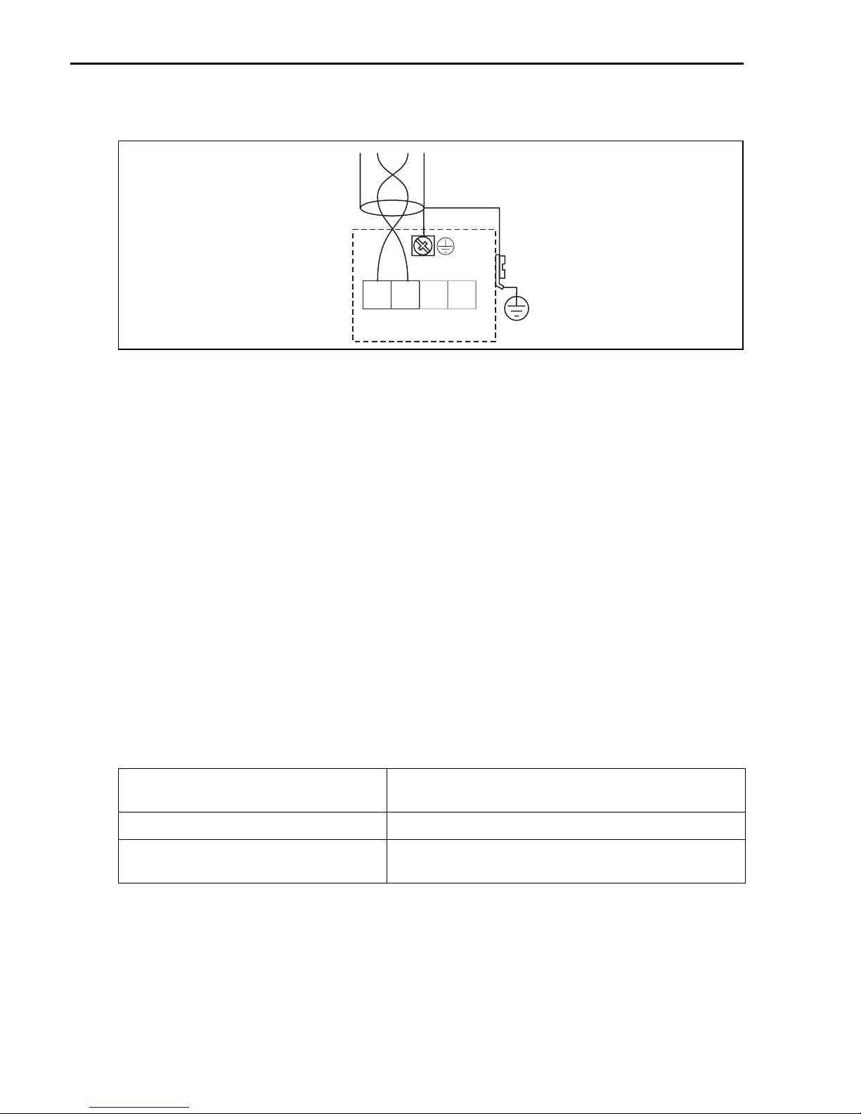
3.5 Cable specification PROFIBUS . . . . . . . . . . . . . . . . . . . . . . . . . . . . . . . . . . . . . . . . . . . . . . . . . . . . . . . . . . . . . . 16
3.6 Connecting the measuring unit . . . . . . . . . . . . . . . . . . . . . . . . . . . . . . . . . . . . . . . . . . . . . . . . . . . . . . . . . . . . . 16
3.7 Screening/potential matching . . . . . . . . . . . . . . . . . . . . . . . . . . . . . . . . . . . . . . . . . . . . . . . . . . . . . . . . . . . . . . 17
3.8 Degree of protection . . . . . . . . . . . . . . . . . . . . . . . . . . . . . . . . . . . . . . . . . . . . . . . . . . . . . . . . . . . . . . . . . . . . . 17
3.9 Post-connection check . . . . . . . . . . . . . . . . . . . . . . . . . . . . . . . . . . . . . . . . . . . . . . . . . . . . . . . . . . . . . . . . . . . 17
4 Operation. . . . . . . . . . . . . . . . . . . . . . . . . . . . . . . . . . . . . . . . . . . . . . . . . . . . . . 18
4.1 General structure of the operating menu . . . . . . . . . . . . . . . . . . . . . . . . . . . . . . . . . . . . . . . . . . . . . . . . . . . . . . 18
4.2 Display and operating elements . . . . . . . . . . . . . . . . . . . . . . . . . . . . . . . . . . . . . . . . . . . . . . . . . . . . . . . . . . . . . 19
4.3 Device address . . . . . . . . . . . . . . . . . . . . . . . . . . . . . . . . . . . . . . . . . . . . . . . . . . . . . . . . . . . . . . . . . . . . . . . . . 22
5 Commissioning . . . . . . . . . . . . . . . . . . . . . . . . . . . . . . . . . . . . . . . . . . . . . . . . . 23
5.1 Function check . . . . . . . . . . . . . . . . . . . . . . . . . . . . . . . . . . . . . . . . . . . . . . . . . . . . . . . . . . . . . . . . . . . . . . . . . 23
5.2 Switching on the measuring device . . . . . . . . . . . . . . . . . . . . . . . . . . . . . . . . . . . . . . . . . . . . . . . . . . . . . . . . . . 23
5.3 Overview Basic Setup . . . . . . . . . . . . . . . . . . . . . . . . . . . . . . . . . . . . . . . . . . . . . . . . . . . . . . . . . . . . . . . . . . . . 24
5.4 Basic Setup with the device display . . . . . . . . . . . . . . . . . . . . . . . . . . . . . . . . . . . . . . . . . . . . . . . . . . . . . . . . . . 26
5.5 Envelope curve with the instrument display . . . . . . . . . . . . . . . . . . . . . . . . . . . . . . . . . . . . . . . . . . . . . . . . . . . 35
2 Endress+Hauser
Page 3

Micropilot M FMR244 PROFIBUS PA Safety instructions
1 Safety instructions
1.1 Designated use
The Micropilot M is a compact radar level transmitter for the continuous, contactless
measurement of liquids, pastes, sludge and solids. The device can also be freely mounted outside
closed metal vessels because of its operating frequency of about 26 GHz and a maximum
radiated pulsed energy of 1 mW (average power output 1μW). Operation is completely harmless
to humans and animals.
1.2 Installation, commissioning and operation
• The instrument must only be installed, connected, commissioned and maintained by qualified
and authorized specialists (e.g. electrical technicians) in full compliance with the instructions
in this manual, the applicable norms, legal regulations and certificates (depending on the
application).
• The specialist must have read and understood this manual and must follow the instructions it
contains. If you are unclear on anything in these Brief Operating Instructions, you must read
the Operating Instructions (on the CD-ROM). The Operating Instructions provide detailed
information on the instrument/measuring system.
• The instrument may only be modified or repaired if such work is expressly permitted in the
Operating Instructions (see CD-ROM).
• If faults cannot be rectified, the instrument must be taken out of service and secured against
unintentional commissioning.
• Do not operate damaged instruments. Mark them as defective.
1.3 Operational safety and process safety
• Alternative monitoring measures must be taken to ensure operational safety and process safety
during confiugration, testing and maintenance work on the instrument.
• The instrument is safely built and tested according to state-of-the-art technology and has left
the factory in perfect condition as regards technical safety. The applicable regulations and
European standards have been taken into account.
• Pay particular attention to the technical data on the nameplate.
• If the instrument is to be installed in an explosion hazardous area, then the specifications in
the certificate as well as all national and local regulations must be observed. The instrument
is accompanied by separate "Ex documentation", which is an integral part of this Operating
Instructions. The installation regulations, connection values and Safety Instructions listed in
this Ex document must be observed. The documentation number of the related Safety Instructions is also indicated.
Endress+Hauser 3
Page 4

Safety instructions Micropilot M FMR244 PROFIBUS PA
1.3.1 FCC approval
This instrument complies with part 15 of the FCC Rules. Operation is subject to the following
two conditions:
1. This instrument may not cause harmful interference, and
2. this instrument must accept any interference received, including interference that may
cause undesired operation.
Caution!
"
Changes or modifications not expressly approved by the part responsible for compliance could
void the user’s authority to operate the equipment.
1.4 Return
Follow the instructions on returning the instrument as outlined in the Operating Instructions on
the CD-ROM provided.
1.5 Safety icons
Safety conventions
Warning!
#
"
!
A warning highlights actions or procedures which, if not performed correctly, will lead to personal injury,
a safety hazard or destruction of the instrument.
Caution!
Caution highlights actions or procedures which, if not performed correctly, may lead to personal injury or
incorrect functioning of the instrument.
Note!
A note highlights actions or procedures which, if not performed correctly, may indirectly affect operation
or may lead to an instrument response which is not planned.
4 Endress+Hauser
Page 5
Micropilot M FMR244 PROFIBUS PA Mounting
t
2 Mounting
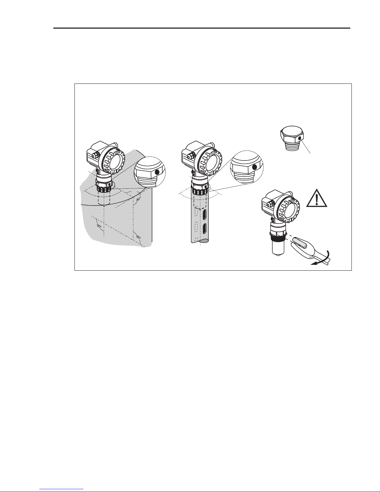
2.1 Quick installation guide
#
Observe orientation when installing!
Installation in tank (free space):
Mark on process connector facing
the nearest tank wall!
90°90°
90°
90°
90°
90°
Installation in stilling well:
Mark on process connector
pointed towards the slots
or vent holes!
mark at threaded boss
90°90°
Caution!
Tighten instrumen
only at the
threaded boss.
AF 60
60
max. torque: 20 Nm (14.75 lbf ft)
L00-FMR244xx-17-00-00-en-006
2.2 Incoming acceptance, transport, storage
2.2.1 Incoming acceptance
Check the packing and contents for any signs of damage. Check the shipment, make sure
nothing is missing and that the scope of supply matches your order.
2.2.2 Transport
Caution!
"
Follow the safety instructions and transport conditions for instrument of more than 18 kg
(39.69 lbs). Do not lift the measuring instrument by its housing in order to transport it.
2.2.3 Storage
Pack the measuring instrument so that is protected against impacts for storage and transport. The
original packing material provides the optimum protection for this.
The permissible storage temperature is -40 °C to +80 °C (-40 °F to +176 °F) or
-50 °C to +80 °C (-58 °F to +176 °F).
Endress+Hauser 5
Page 6
Mounting Micropilot M FMR244 PROFIBUS PA
2.3 Installation
2.3.1 Mounting kit
Beside a key AF 60 for installation you need the following tool:
• 4 mm (0.16 in) Allen wrench for turning the housing.
2.3.2 General installation instructions
• Marker is aligned towards tank wall.
• Install the device using the threaded boss (AF 60) only. Observe the max. torque of 20 Nm
(14.75 lbf ft)!
• After mounting, the housing can be turned 350° in order to simplify access to the display and
the terminal compartment, → ä 13.
2.3.3 Installation in tank (free space)
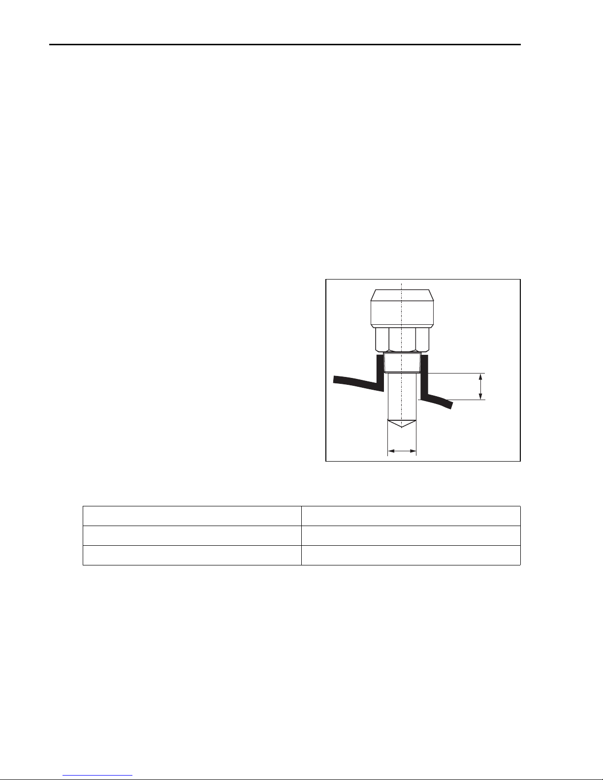
Standard installation - 40 mm (1.57 in)
antenna
• For optimum measurement, the horn antenna
should extend below the nozzle. Nozzle
heights up to 500 mm (19.7 in) can be accepted if this should not be possible due to
mechanical reasons.
!
Note!
Please contact Endress+Hauser for application
with higher nozzle.
• The antenna must be aligned vertically.
Antenna size 40 mm (1½")
D [mm (in)] 39 (1.54)
H [mm (in)] < 85 (3.35)
H
ØD
L00-FMR244xx-17-00-00-en-002
6 Endress+Hauser
Page 7
Micropilot M FMR244 PROFIBUS PA Mounting
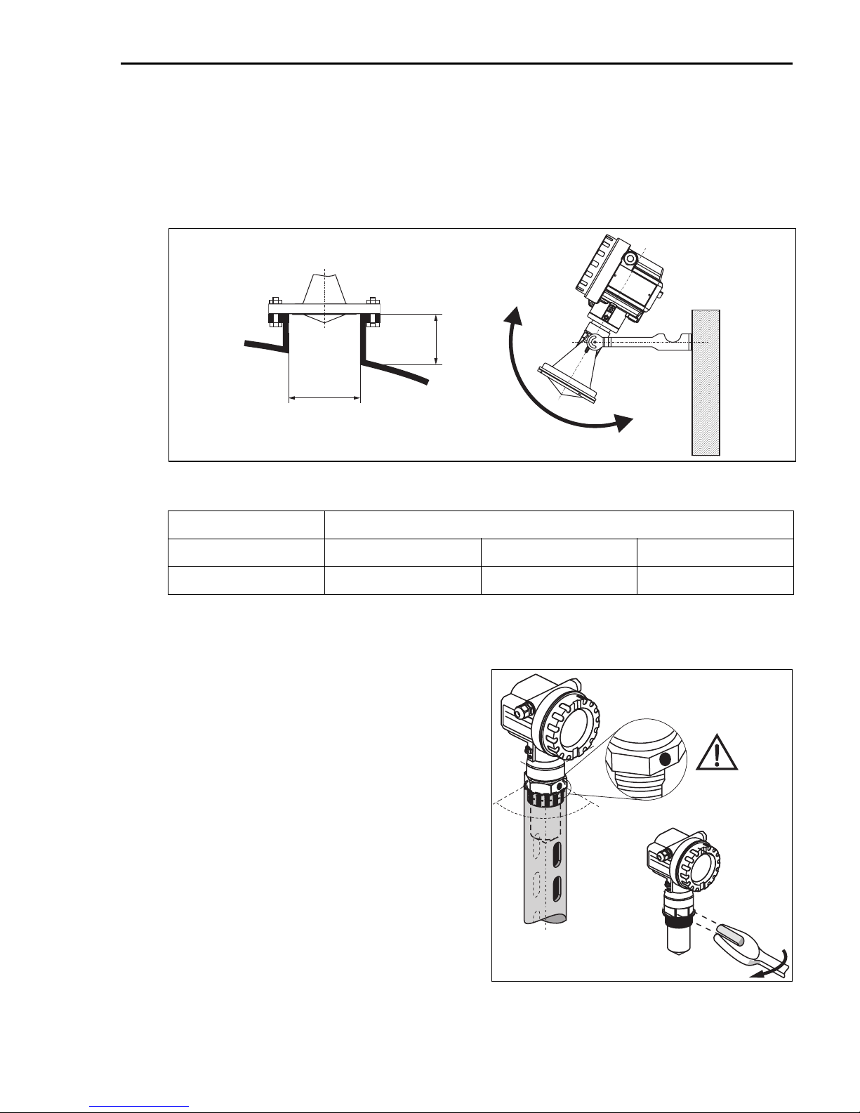
Standard installation - 80 mm (3.15 in) antenna
• The marker is located directly below the housing neck on the stainless steel feedthrough.
• As an option for flange mounting, a variable flange seal (see "Accessories") can be used to align
the device (solid applications).
• If using a mounting bracket , the device can be aligned at the bracket (solid applications).
H
ØD
L00-FMR244xx-17-00-00-xx-011
Antenna size 80 mm (3")
D [mm (in)] 80 (3.15) 100 (3.94) 150 (5.91)
H [mm (in)] < 500 (19.7) < 500 (19.7) < 500 (19.7)
2.3.4 Installation in stilling well
For installations in a stilling well, follow the
engineering hints (→ ä 9) and note the
following points:
• Marker is aligned toward slots.
• Measurements can be performed through
an open ball valve without any problems.
90°90°
Caution!
Use only the
threaded boss
Endress+Hauser 7
max. torque: 20 Nm (14.75 lbf ft)
L00-FMR244xx-17-00-00-en-007
AF 60
60
Page 8
Mounting Micropilot M FMR244 PROFIBUS PA
2.3.5 Orientation
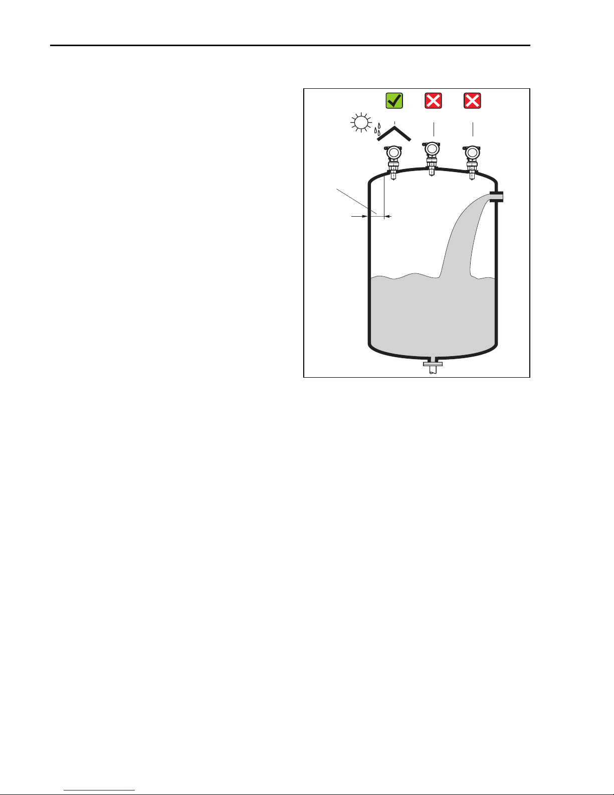
• Recommended distance (1) wall - outer
edge of nozzle: ~1/6 of tank diameter.
Nevertheless the device should not be
234
installed closer than 15 cm (5.91 in) to the
tankwall.
• Not in the centre (3), interference can
cause signal loss.
• Not above the fill stream (4).
1
• It is recommended to use a weather protection cover (2) in order to protect the
transmitter from direct sun or rain.
Assembly and disassembly is simply done
by means of a tension clamp (see Operation Instruction on the CD-ROM).
L00-FMR2xxxx-17-00-00-xx-008
8 Endress+Hauser
Page 9
Micropilot M FMR244 PROFIBUS PA Mounting
2.3.6 Engineering hints
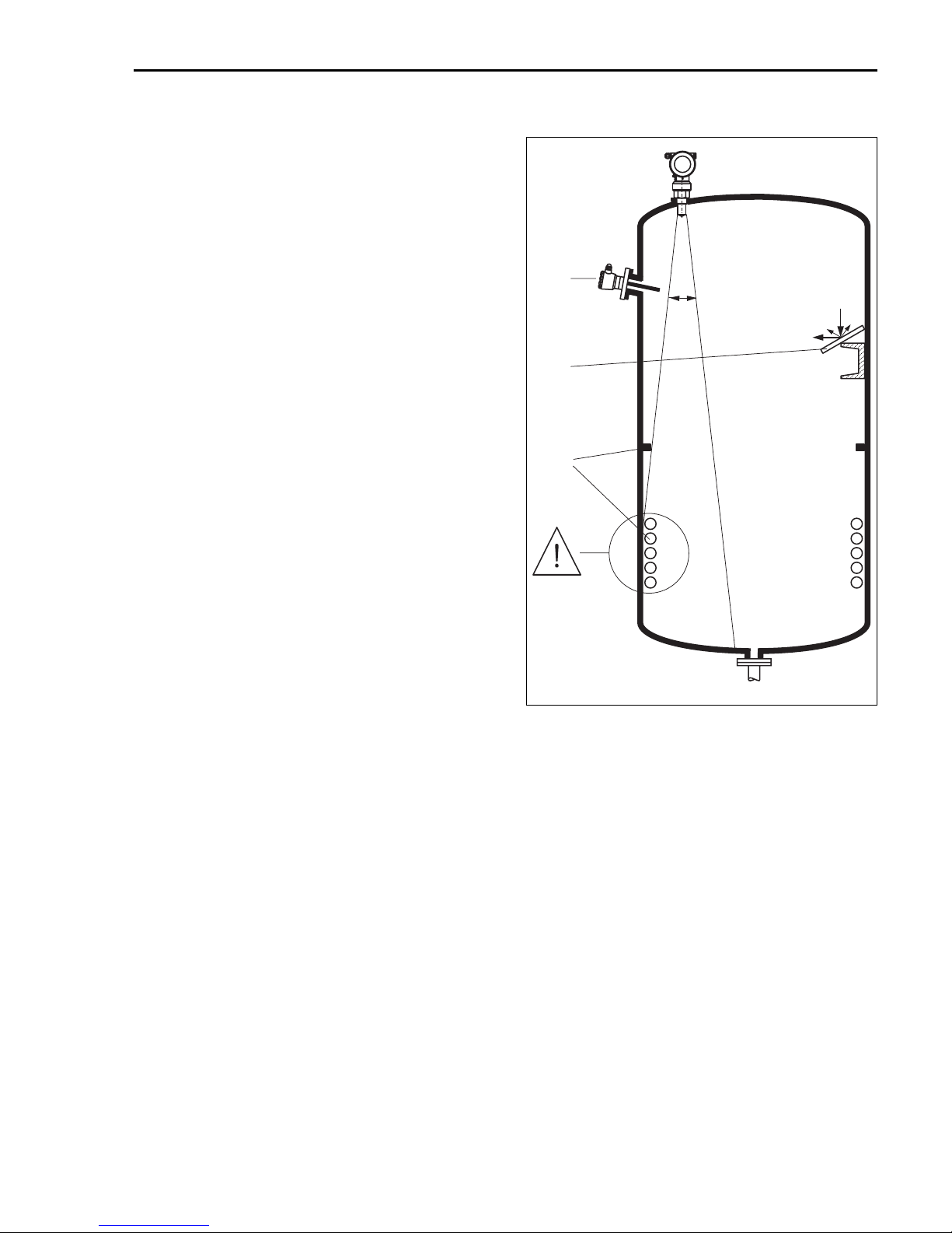
Tank installations
• Avoid any installations (1), like limit
switches, temperature sensors, etc., inside
the signal beam (→ ä 10).
• Symmetrical installations (2), i.e. vacuum
rings, heating coils, baffles, etc., can also
interfere with the measurement.
1
a
Optimization options
• Antenna size: the bigger the antenna, the
smaller the beam angle, the less
3
interference echoes.
• Mapping: the measurement can be
optimized by means of electronic
suppression of interference echoes.
• Antenna alignment: refer to
2
BA249F/00/EN.
• Stilling well: a stilling well can always be
used to avoid interference.
• Metallic screens (3) mounted at a slope
spread the radar signals and can,
therefore, reduce interference echoes.
• For mounting in solid applications use the
variable flange seal to align the device
towards the product surface (see
TI345F/00/EN, "Accessories").
L00-FMR2xxxx-17-00-00-xx-009
Please contact Endress+Hauser for further
information.
Endress+Hauser 9
Page 10
Mounting Micropilot M FMR244 PROFIBUS PA
2.3.7 Beam angle
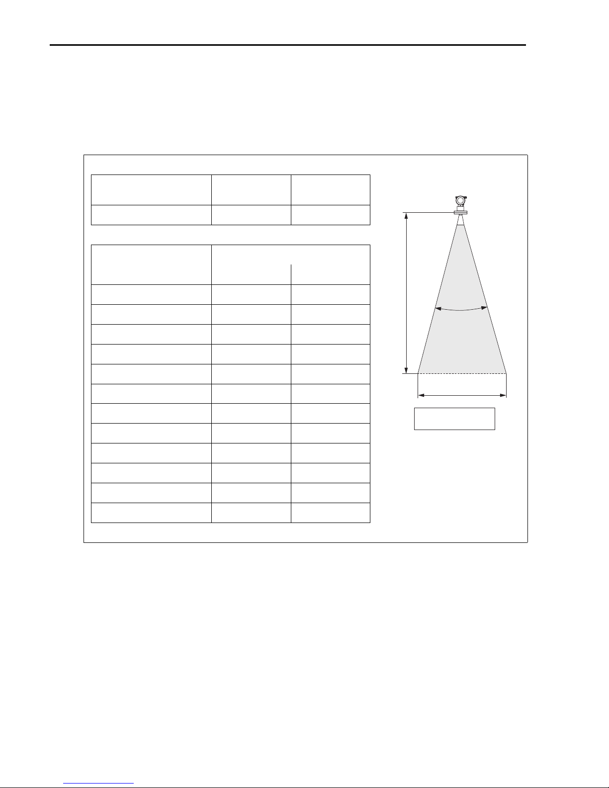
The beam angle is defined as the angle α where the energy density of the radar waves reaches
half the value of the maximum energy density (3dB-width). Microwaves are also emitted outside
the signal beam and can be reflected off interfering installations. Beam diameter W as function
of antenna type (beam angle α) and measuring distance D:
Antenna size
(horn diameter)
Beam angle α 23° 10°
Measuring
distance (D)
3 m (9.8 ft) 1,22 m (4 ft) 0,53 m (1.7 ft)
6 m (20 ft) 2,44 m (8 ft) 1,05 m (3.4 ft)
9 m (30 ft) 3,66 m (12 ft) 1,58 m (5.2 ft)
12 m (39 ft) 4,88 m (16 ft) 2,10 m (6.9 ft)
15 m (49 ft) 6,10 m (20 ft) 2,63 m (8.6 ft)
20 m (66 ft) 8,14 m (27 ft) 3,50 m (11 ft)
25 m (82 ft) 10,17 m (33 ft) 4,37 m (14 ft)
30 m (98 ft) − 5,25 m (17 ft)
35 m (115 ft) − 6,12 m (20 ft)
40 m (131 ft) − 7,00 m (23 ft)
40 mm (1½") 80 mm (3")
Beam diameter (W)
40 mm (1½") 80 mm (3")
D
a
W
a
tan
_
2
..
=
W
2
D
L00-FMR2xxxx-14-00-06-de-027
45 m (148 ft) − 7,87 m (26 ft)
60 m (197 ft) − 10,50 m (34 ft)
2.3.8 Measuring conditions in liquids
• In case of boiling surfaces, bubbling or tendency for foaming, use FMR230 or FMR231.
Depending on its consistence, foam can either absorb microwaves or reflect them off the foam
surface. Measurement is possible under certain conditions.
• In case of heavy steam development or condensate the max. measuring range of FMR240
may decrease depending on density, temperature and composition of the steam
È use FMR230 or FMR231.
10 Endress+Hauser
Page 11
Micropilot M FMR244 PROFIBUS PA Mounting
• For the measurement of absorbing gases such as ammonia NH3 or some fluorocarbons1),
please use FMR230 in a stilling well.
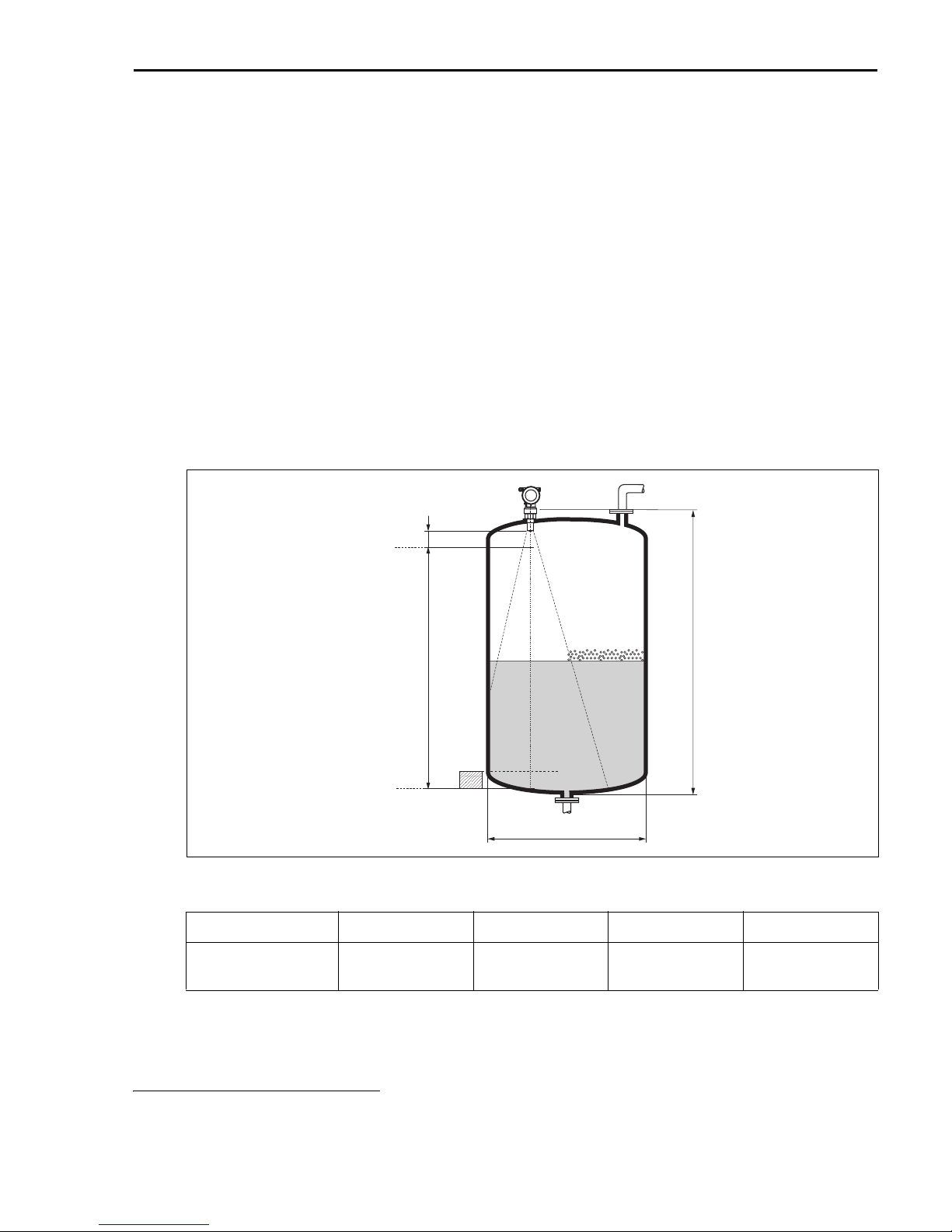
• The measuring range begins, where the beam hits the tank bottom. Particularly with dish
bottoms or conical outlets the level cannot be detected below this point.
• In case of media with a low dielectric constant (groups A and B), the tank bottom can be
visible through the medium at low levels (low height C). Reduced accuracy has to be expected
in this range. If this is not acceptable, we recommend positioning the zero point at a distance
C (see Fig.) above the tank bottom in these applications.
• In principle it is possible to measure up to the tip of the antenna with FMR230/231/240.
However, due to considerations regarding corrosion and build-up, the end of the measuring
range should not be chosen any closer than A (see Fig.) to the tip of the antenna.
For FMR244/245, the end of measuring range should not be chosen closer than A (see Fig.)
to the tip of the antenna, especially if there is development of condensate.
• The smallest possible measuring range B depends on the antenna version (see Fig.).
• The tank diameter should be greater than D (see Fig.), the tank height at least H (see Fig.).
0%
A
B
C
ØD
50 to 250
(1.97 to 9.84)
H
L00-FMR2xxxx-17-00-00-en-009
> 0,2 (0.7) > 0,3 (1)
100%
A [mm (in)] B [m (ft)] C [mm (in)] D [m (ft)] H [m (ft)]
150 (5.91) > 0,2 (0.7)
1) Affected compounds are e.g. R134a, R227, Dymel 152a
Endress+Hauser 11
Page 12
Mounting Micropilot M FMR244 PROFIBUS PA
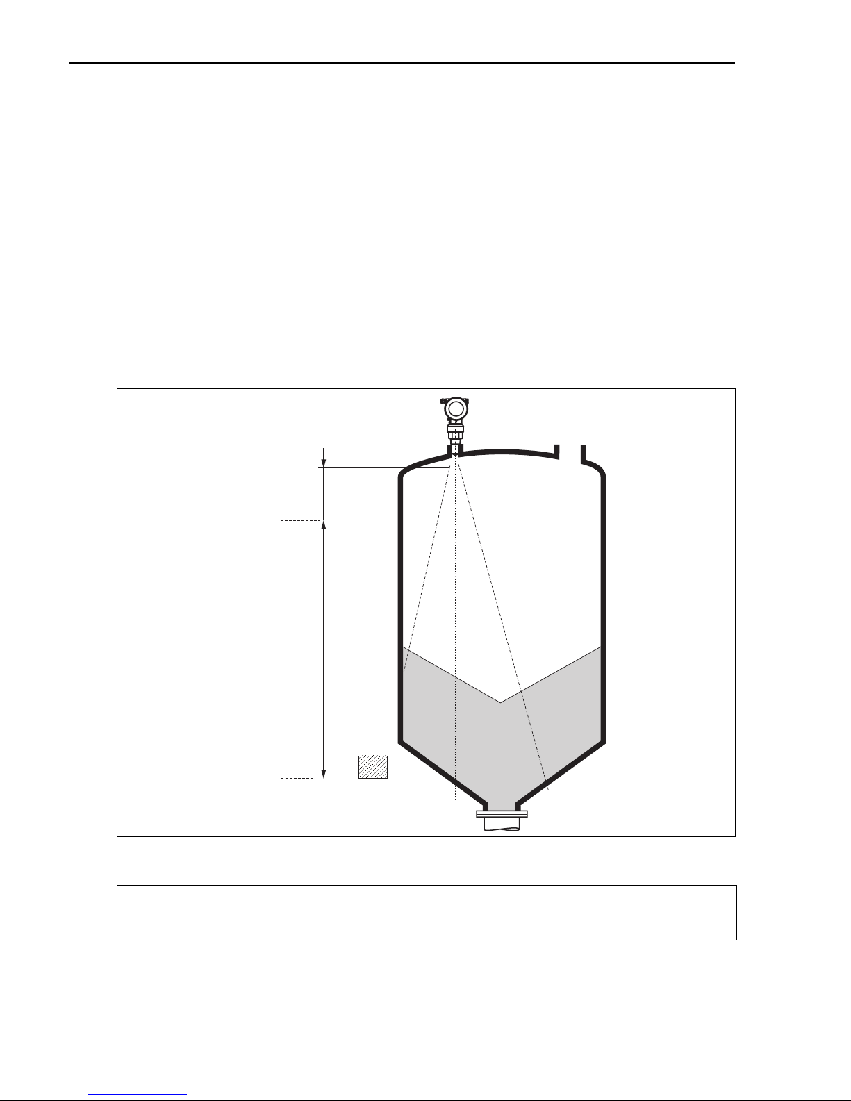
2.3.9 Measuring conditions in solids
• The measuring range begins, where the beam hits the bottom. Particularly with conical outlets
the level cannot be detected below this point.
The maximum measuring range can be increased in such applications by using a top target
positioner (see TI345F/00/EN).
• In case of media with a low dielectric constant (groups A and B), the bottom can be visible
through the medium at low levels. In order to guarantee the required accuracy in these cases,
it is recommended to position the zero-point at a distance C above the bottom (see Fig.).
• In principle it is possible to measure up to the tip of the antenna with the Micropilot M.
However, due to considerations regarding abrasion and build-up and depending on the
orientation of the product surface (angel of repose), the end of the measuring range should be
at a distance of A (see Fig). If required, and if some conditions (high DC value, flat angle of
repose) are met, shorter distances can be achieved.
100%
0%
A
Measuring range
C
L00-FMR250xx-17-00-00-en-001
A [mm (in)] C [mm (in)]
approx. 400 (15.7) 50 to 150 (1.97 to 5.91)
12 Endress+Hauser
Page 13
Micropilot M FMR244 PROFIBUS PA Mounting
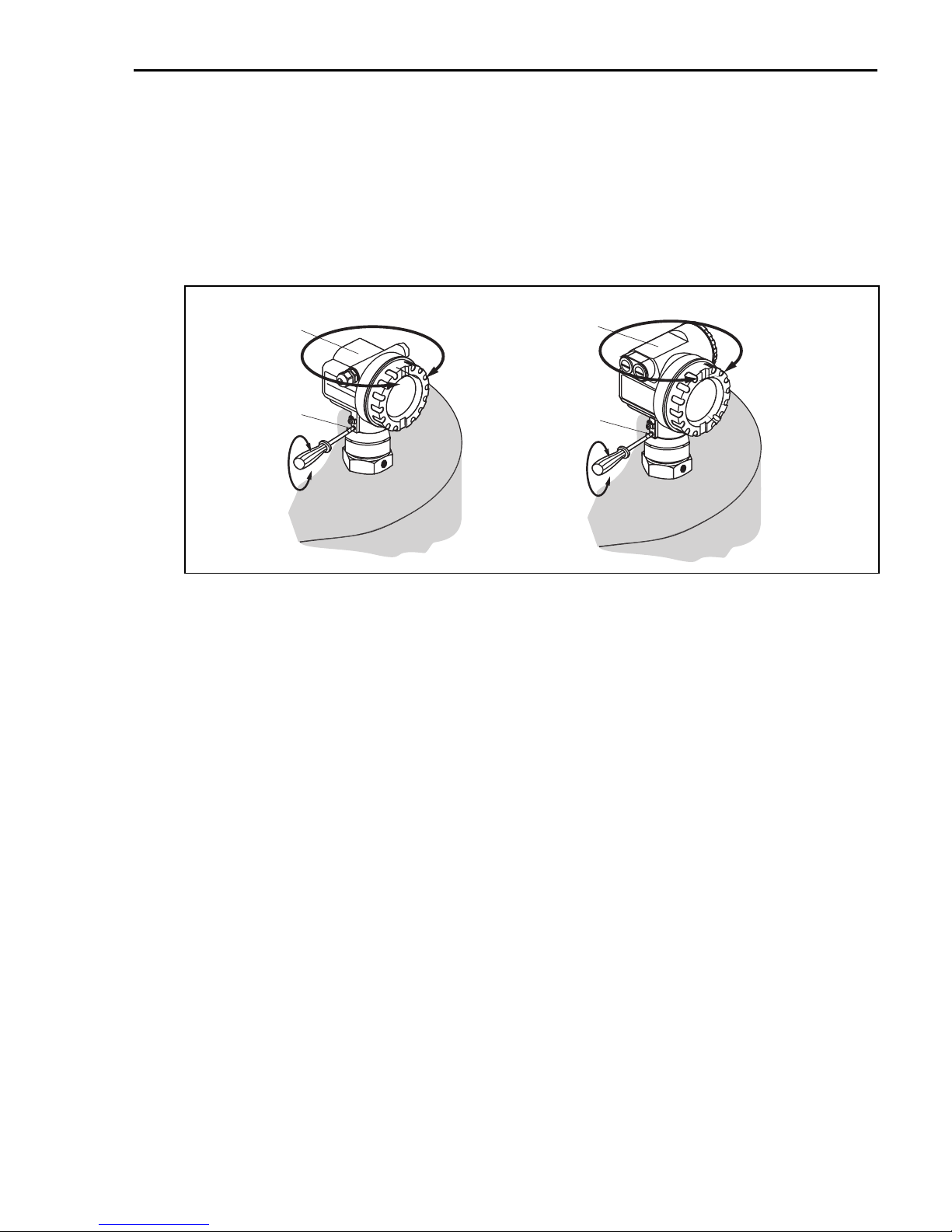
2.3.10 Turn housing
After mounting, the housing can be turned 350° in order to simplify access to the display and
the terminal compartment. Proceed as follows to turn the housing to the required position:
• Undo the fixing screws (1).
• Turn the housing (2) in the required direction.
• Tighten up the fixing screws (1).
F12 housing T12 housing
2
1
allen key
4 mm (0.16 in)
max. torque 0.5 Nm (0.37 lbf ft)
2
1
L00-FMR2xxxx-17-00-00-en-011
2.4 Post-installation check
After the measuring instrument has been installed, perform the following checks:
• Is the measuring instrument damaged (visual check)?
• Does the measuring instrument correspond to the measuring point specifications such as process temperature/pressure, ambient temperature, measuring range, etc.?
• Is the flange marking correctly aligned (→ ä 5)?
• Have the flange screws been tightened up with the respective tightening torque?
• Are the measuring point number and labeling correct (visual check)?
• Is the measuring instrument adequately protected against rain and direct sunlight (see Chapter
"Accessories" in the Operating Instruction on the CD-ROM)?
Endress+Hauser 13
Page 14
Wiring Micropilot M FMR244 PROFIBUS PA
ENDRESS+HAUSER
3 Wiring
Warning!
#
When using the measuring instrument in hazardous areas, installation must comply with the
corresponding national standards and regulations and the Safety Instructions or Installation or
Control Drawings.
Caution!
"
Before connection please note the following:
• The power supply must be identical to the data on the nameplate.
• Switch off power supply before connecting up the instrument.
• Use screened, twisted wire pair.
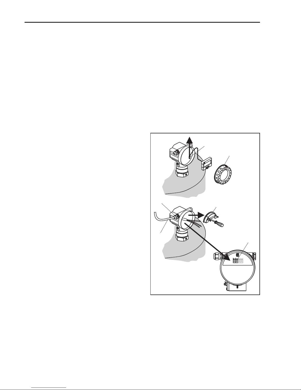
3.1 Wiring in F12 housing
1. Unscrew housing cover (1).
2. Remove any display (2) if fitted.
3. Remove cover plate from terminal
compartment (3).
4. Pull out terminal module (4) slightly
using "pulling loop".
5. Insert cable (5) through gland (6).
6. Make connection (see terminal
assignment).
7. Re-insert terminal module (4).
8. Tighten cable gland (6).
9. Tighten screws on cover plate (3).
10. Insert display (2) if fitted.
11. Screw on housing cover (1).
12. Switch on power supply.
2
1
6
5
3
4
1234
14 Endress+Hauser
L00-FMR244xx-04-00-00-xx-001
Page 15
Micropilot M FMR244 PROFIBUS PA Wiring
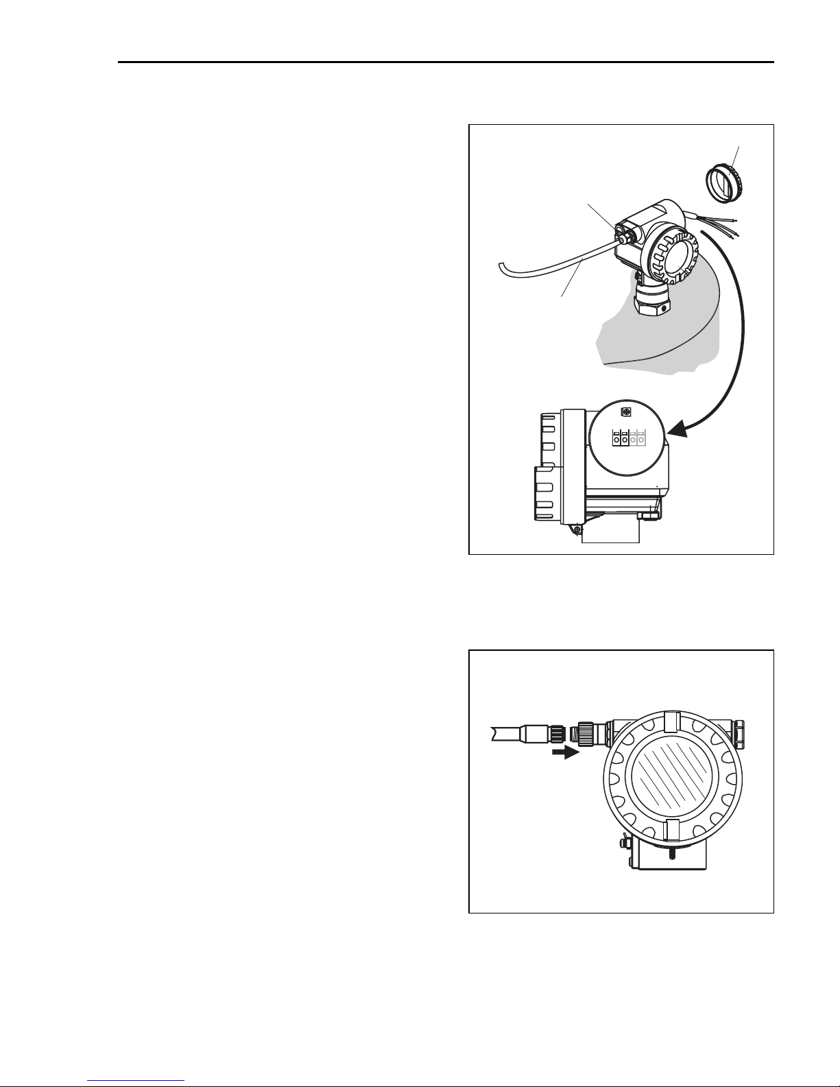
3.2 Wiring in T12 housing
1. Unscrew housing cover (1).
2. Insert cable (2) through gland (3).
3. Connect cable screen to the grounding
terminal (4) within the terminal
compartment.
4. Make connection (see terminal
assignment).
5. Tighten cable gland (3).
6. Screw on housing cover (1).
7. Switch on power supply.
1
3
2
1234
3.3 Wiring with M12 plug
1. Insert plug (1) into bushing (2).
2. Screw firmly.
3. Ground the device according to the
desired safety concept.
L00-FMR244xxx-04-00-00-xx-002
2
1
L00-FMP4xxxx-04-00-00-xx-002
Endress+Hauser 15
Page 16
Wiring Micropilot M FMR244 PROFIBUS PA
3.4 Terminal assignment
plant ground
3
4
L00-FMP4xxxx-04-00-00-en-007
2
1
PA- PA+
3.5 Cable specification PROFIBUS
Twisted, screened pairs must be used. The following cable types can be used, for example:
• Siemens 6XV1 830-5BH10 (grey)
• Kerpen CEL-PE/OSCR/PCV/FRLA FB-02YS(ST)YFL (grey)
• Belden 3076F (orange)
3.6 Connecting the measuring unit
Cable entry
• Cable gland: M20x1.5
• Cable entry: G½ or ½NPT
• PROFIBUS PA M12 plug
Supply voltage
The following values are the voltages across the terminals directly at the instrument:
Supply voltage 9 V to 32 V (non Ex)
Polarity sensitive No
FISCO / FNICO compliant in accordance to
IEC60079-27
Current consumption
• Device basic current: max. 13 mA
• Error current FDE (Fault Disconnection Electronic): 0 mA
16 Endress+Hauser
max. voltage: 35 V
Yes
Page 17

Micropilot M FMR244 PROFIBUS PA Wiring
Overvoltage protector
The level transmitter Micropilot M with T12-housing (housing version "D", see ordering
information) is equipped with an internal overvoltage protector (600 V surge arrester) according
to DIN EN 60079-14 or IEC 60060-1 (impulse current test 8/20 μs, Î = 10 kA, 10 pulses).
Connect the metallic housing of the Micropilot M to the tank wall or screen directly with an
electrically conductive lead to ensure reliable potential matching.
Connection with M12 plug
The Micropilot M PROFIBUS PA sensor version with M12 plug is supplied ready wired and need
only be connected to the bus by means of a suitable cord set.
3.7 Screening/potential matching
• You achieve optimum screening against disturbances if the screening is connected on both
sides (in the cabinet and on the device). If you have to reckon with potential equalisation currents in the plant, only earth screening on one side, preferably at the transmitter.
• When using in hazardous areas, you must observe the applicable regulations and the separate
Ex documentation.
3.8 Degree of protection
• with closed housing: IP65, NEMA4X (higher degree of protection e. g. IP68 on request)
• with open housing: IP20, NEMA1 (also ingress protection of the display)
• antenna: IP68 (NEMA6P)
Caution!
"
Degree of protection IP68 NEMA 6P applies for M12 PROFIBUS PA plugs only when the
PROFIBUS cable is plugged in.
3.9 Post-connection check
After wiring the measuring instrument, perform the following checks:
• Is the terminal allocation correct (→ ä 16)?
• Is the cable gland tight?
• Is the M12 plug screwed tight?
• Is the housing cover screwed tight?
• If auxiliary power is available:
Is the instrument ready for operation and does the liquid crystal display show any value?
Endress+Hauser 17
Page 18
Operation Micropilot M FMR244 PROFIBUS PA
4Operation
4.1 General structure of the operating menu
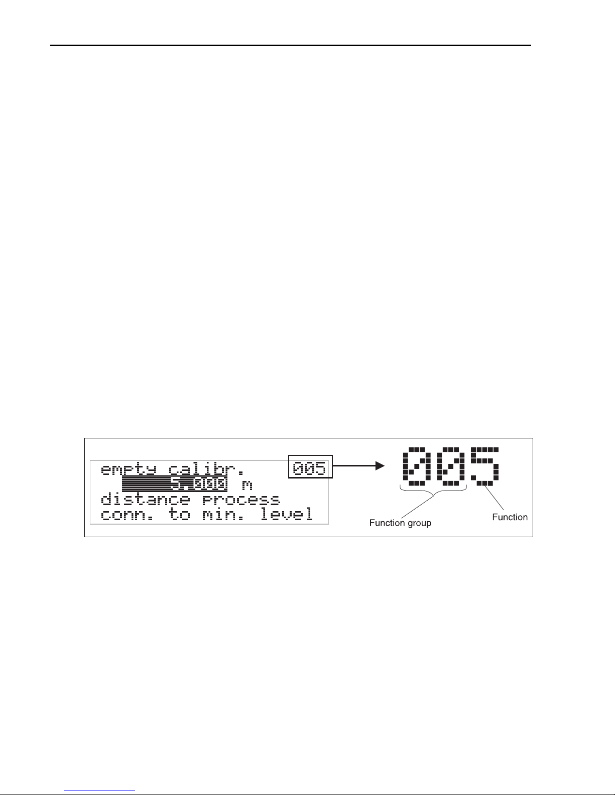
The operating menu is made up of two levels:
• Function groups (00, 01, 03, …, 0C, 0D):
The individual operating options of the instrument are split up roughly into different function
groups. The function groups that are available include, e.g.: "basic setup", "safety
settings.", "output", "display", etc.
• Functions (001, 002, 003, …, 0D8, 0D9):
Each function group consists of one or more functions. The functions perform the actual
operation or parameterisation of the instrument. Numerical values can be entered here and
parameters can be selected and saved. The available functions of the "basic setup" (00)
function group include, e.g.: "tank shape" (002), "medium property" (003), "process
cond." (004), "empty calibr." (005), etc.
If, for example, the application of the instrument is to be changed, carry out the following procedure:
1. Select the "basic setup" (00) function group.
2. Select the "tank shape" (002) function (where the existing tank shape is selected).
4.1.1 Identifying the functions
For simple orientation within the function menus, for each function a position is shown on the
display.
L00-FMRxxxxx-07-00-00-en-005
The first two digits identify the function group:
• basic setup 00
• safety settings 01
• linearisation 04
...
18 Endress+Hauser
Page 19
Micropilot M FMR244 PROFIBUS PA Operation
E
N
D
RE
SS
+HA
U
SE
R
MI
C
R
OP
I
L
OTII
I
P65
O
rd
e
r
Co
d
e:
Ser.-N
o
.:
Messb
e
reich
M
e
a
su
ri
ng
range
U
16...3
6
V
DC
4...
2
0
mA
max.
20
m
MadeinGermany Maulburg
T>
7
0
°C
:
A
t
>85°
C
The third digit numbers the individual functions within the function group:
• basic setup 00 → • tank shape 002
• medium property 003
• process cond 004
...
Here after the position is always given in brackets (e.g. "tank shape" (002)) after the described
function.
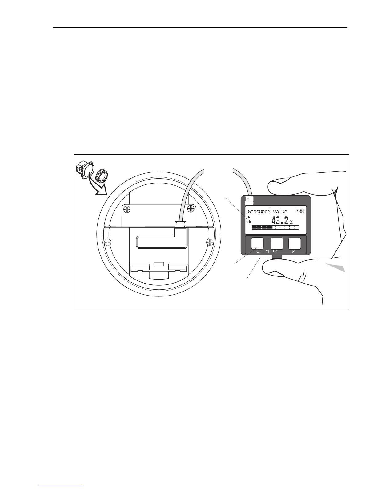
4.2 Display and operating elements
Four lines with 20 characters each. Display contrast adjustable through key combination.
E
N
DR
MI
E
O
SS+H
r
C
d
e
RO
r
C
S
o
e
d
P
r
e
A
.
-
IL
:
N
USE
o
OT
.
:
R
II
M
e
s
s
M
b
e
e
r
a
e
s
i
c
u
h
r
in
g
r
a
n
g
e
U
m
1
a
6
x
.
.
.
4
.
2
3
.
.
0
6
.
2
m
V
0
D
m
C
A
I
P65
T>
A
7
0
°
C
:
t
>
8
5
°C
MadeinGermany Maulburg
(liquid crystal display)
Symbols
LCD
ENDRESS + HAUSER
–
+
E
3 keys
snap-fit
L00-FMxxxxxx-07-00-00-en-001
The LCD display can be removed to ease operation by simply pressing the snap-fit (see graphic
above). It is connected to the device by means of a 500 mm (19.7 in) cable.
Endress+Hauser 19
Page 20
Operation Micropilot M FMR244 PROFIBUS PA
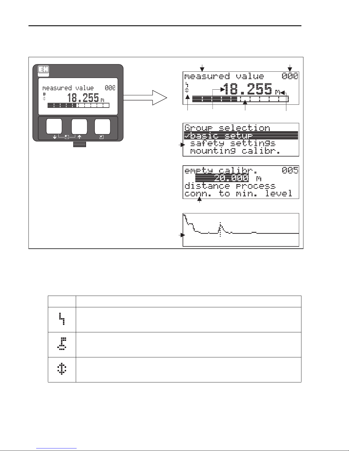
4.2.1 Display
Headline Position indicator
ENDRESS + HAUSER
–
+
E
4.2.2 Display symbols
Selection list
Envelope
curve
Symbol
Help text
0.00
Main value
+21dB 09C
Bargraph
Unit
10.002.305m
L00-FMRxxxxx-07-00-00-en-003
The following table describes the symbols that appear on the liquid crystal display:
Symbol Meaning
ALARM_SYMBOL
This alarm symbol appears when the instrument is in an alarm state. If the symbol flashes, this indicates a
warning.
LOCK_SYMBOL
This lock symbol appears when the instrument is locked, i.e. if no input is possible.
COM_SYMBOL
This communication symbol appears when a data transmission via e.g. HART, PROFIBUS PA or
FOUNDATION Fieldbus is in progress.
20 Endress+Hauser
Page 21

Micropilot M FMR244 PROFIBUS PA Operation
4.2.3 Key assignment
Key(s) Meaning
O
S
X
O
S
and S and
O
or
or
or
F
and
or
and
V
W
Z
F
F
F
Navigate upwards in the selection list.
Edit numeric value within a function.
Navigate downwards in the selection list.
Edit numeric value within a function.
Navigate to the left within a function group.
Navigate to the right within a function group, confirmation.
Contrast settings of the LCD.
Hardware lock / unlock
After a hardware lock, an operation of the instrument via display or communication is
not possible!
The hardware can only be unlocked via the display. An unlock parameter must be
entered to do so.
Endress+Hauser 21
Page 22
Operation Micropilot M FMR244 PROFIBUS PA
EN
D
R
ESS+HA
USER
MIC
R
OPILOT I
I
IP 65
O
r
d
er
C
ode
:
Se
r
.N
o.:
M
e
ss
b
er
ei
c
h
Mea
s
ur
i
ng
ra
ng
e
U 16.
..3
6V
D
C
4...2
0
mA
m
a
x.20
m
Made in Germany Maulburg
T
>7
0°C :
A
t
>85°
C
4.3 Device address
4.3.1 Software addressing
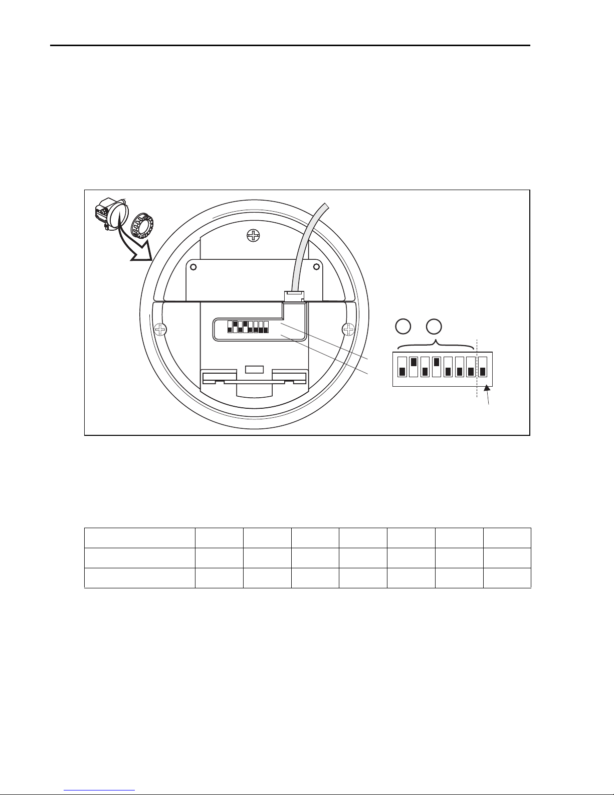
Software addressing comes into operation, when DIP-switch 8 is in the position "ON".
BA034S/04/EN describes, how to set the address in this case.
4.3.2 Hardware addressing
E
N
D
R
M
E
O
I
S
r
C
d
e
S
R
r
+
C
O
S
o
H
e
d
P
r
e
A
.
-
:
I
N
U
L
o
O
S
.
:
T
E
R
I
I
M
e
s
s
M
b
e
e
r
a
e
s
i
c
u
h
r
i
n
g
r
a
n
g
e
U
m
1
a
6
x
.
.
.
4
.
2
3
.
0
.
6
.
2
m
V
0
D
m
C
A
I
P
6
5
T
A
>
7
0
°
C
:
t
>
8
5
°
C
Made in Germany Maulburg
on
off
2
1
SW
HW
6
8
5
3
7
4
2 + 8 = 10
ON
OFF
1234
5678
SW
HW
address
method of
addressing
L00-FMU4xxxx-19-00-00-en-014
Hardware addressing comes into operation, when DIP switch 8 is in the position "HW (OFF)".
In this case the address is determinded by the position of DIP-switches 1 to 7 according to the
following table:
Switch No. 1234567
Value in position "OFF"0000000
Value in position "ON" 1 2 4 8 16 32 64
The new address becomes valid 10 seconds after switching.
It results a new device restart.
22 Endress+Hauser
Page 23
Micropilot M FMR244 PROFIBUS PA Commissioning
5Commissioning
5.1 Function check
Make sure that all final checks have been completed before you start up your measuring point:
• Checklist "Post-installation check", → ä 13.
• Checklist "Post-connection check", → ä 17.
5.2 Switching on the measuring device
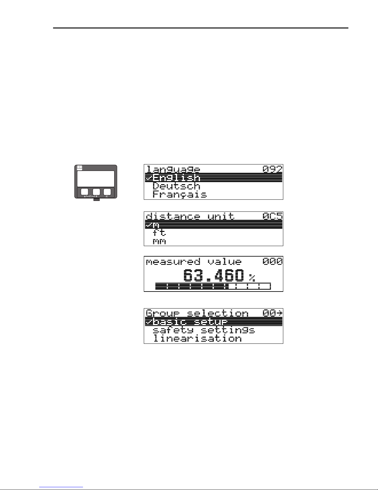
When the instrument is switched on for the first time, the following messages appear in a
sequence of 5 s on the display: software version, communication protocoll and language
selection.
ENDRESS + HAUSER
–
+
E
⇒
⇓
⇓
⇓
Select the language (this
message appears the first
time the instrument is
switched on)
Select the basic unit (this
message appears the first
time the instrument is
switched on)
The current measured
value is displayed
After F is pressed, you
reach the group selection
This selection enables you
to perform the basic setup
Endress+Hauser 23
Page 24
Commissioning Micropilot M FMR244 PROFIBUS PA
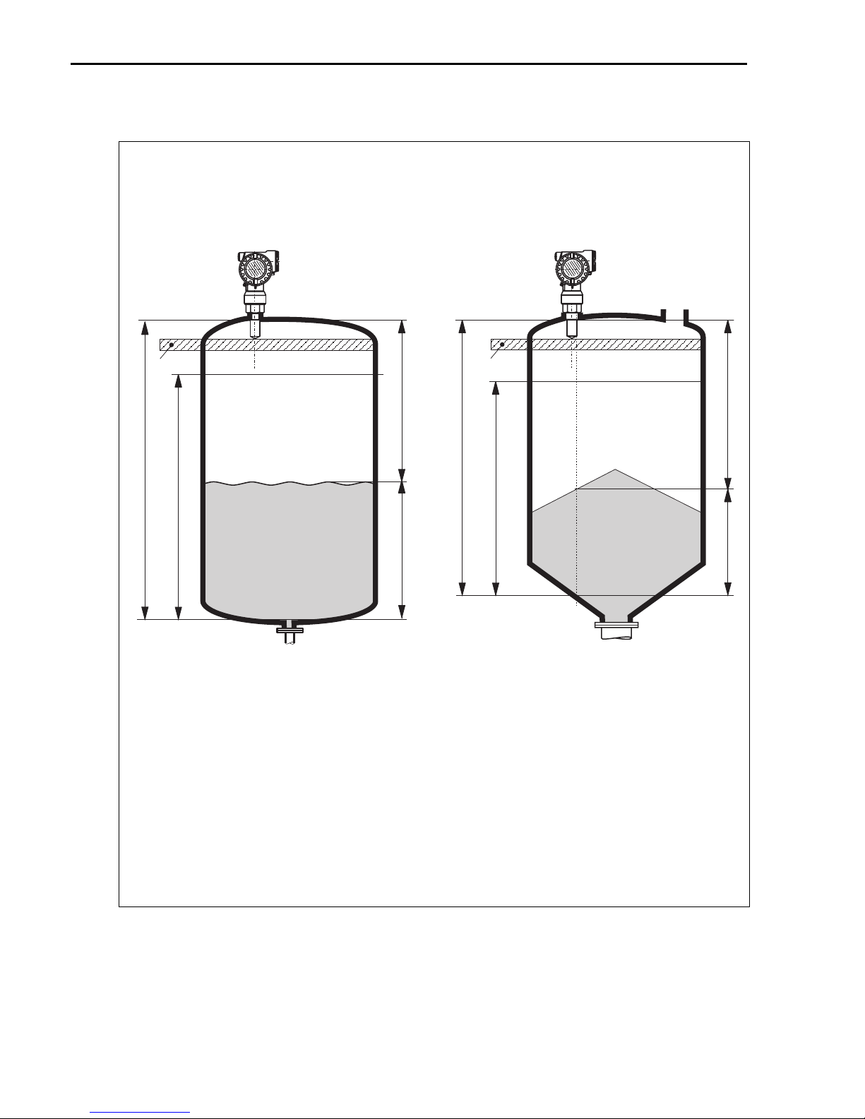
5.3 Overview Basic Setup
level measurement in liquids
flange:
reference point of
measurement
SD
E
F
level measurement in solids
flange:
reference point of
measurement
SD
D
D
E
F
L
L
E = empty calibr. (= zero), setting in 005
F = full calibr. (= span), setting in 006
D = distance (distance flange / product), display in 0A5
L = level, display in 0A6
SD = safety distance, setting in 015
24 Endress+Hauser
L00-FMR244xx-19-00-00-en-003
Page 25

Micropilot M FMR244 PROFIBUS PA Commissioning
Caution!
"
The basic setup is sufficient for successful commissioning in most applications. Complex
measuring operations necessitate additional functions that the user can use to customise the
Micropilot as necessary to suit his specific requirements. The functions available to do this are
described in detail in the BA291F/00/EN.
!
Comply with the following instructions when configuring the functions in the
• Select the functions as described in BA249F/00/EN.
• Some functions can only be used depending on the parameterisation of the instrument. For
example, the pipe diameter of a stilling well can only be entered if "stilling well" was
selected beforehand in the "tank shape" (002) function.
• Certain functions (e.g. starting an interference echo mapping (053)) prompt you to confirm
your data entries. Press
now started.
• If you do not press a key during a configurable time period (
(09)), an automatic return is made to the home position (measured value display).
Note!
• The instrument continues to measure while data entry is in progress, i.e. the current measured
values are output via the signal outputs in the normal way.
• If the envelope curve mode is active on the display, the measured values are updated in a
slower cycle time. Thus, it is advisable to leave the envelope curve mode after the measuring
point has been optimised.
• If the power supply fails, all preset and parameterised values remain safely stored in the
EEPROM.
• All functions are described in detail, as is the overview of the operating menu itself, in the
manual "BA291F - Description of Instrument Functions", which is found on the
enclosed CD-ROM
• The default values of the parameters are typed in boldface.
or S to select "YES" and press F to confirm. The function is
O
→ function group "display"
"basic setup"
(00):
Endress+Hauser 25
Page 26
Commissioning Micropilot M FMR244 PROFIBUS PA
5.4 Basic Setup with the device display
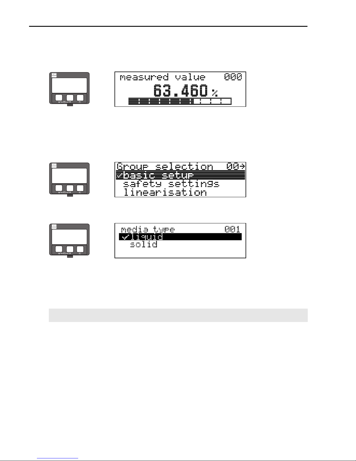
5.4.1 Function "measured value" (000)
ENDRESS + HAUSER
–
+
E
This function displays the current measured value in the selected unit (see "customer
unit"(042) function). The number of digits after decimal point can be selected in the "no.of
decimals" (095) function.
5.4.2 Function group "basic setup" (00)
ENDRESS + HAUSER
⇒
⇒
–
+
E
5.4.3 Function "media type" (001)
ENDRESS + HAUSER
⇒
–
+
E
This function is used to select the media type.
Selection:
• liquid
• solid
With the selection "liquid" only the following
functions can be adjusted:
• tank shape 002 • vessel / silo 00A
• medium property 003 • medium property 00B
• process cond. 004 • process cond. 00C
• empty calibr. 005 • empty calibr. 005
• full calibr. 006 • full calibr. 006
• pipe diameter 007 • check distance 051
• check distance 051 • range of mapping 052
• range of mapping 052 • start mapping 053
• start mapping 053 • ....
•...
With the selection "solids" only the following
functions can be adjusted:
26 Endress+Hauser
Page 27
Micropilot M FMR244 PROFIBUS PA Commissioning
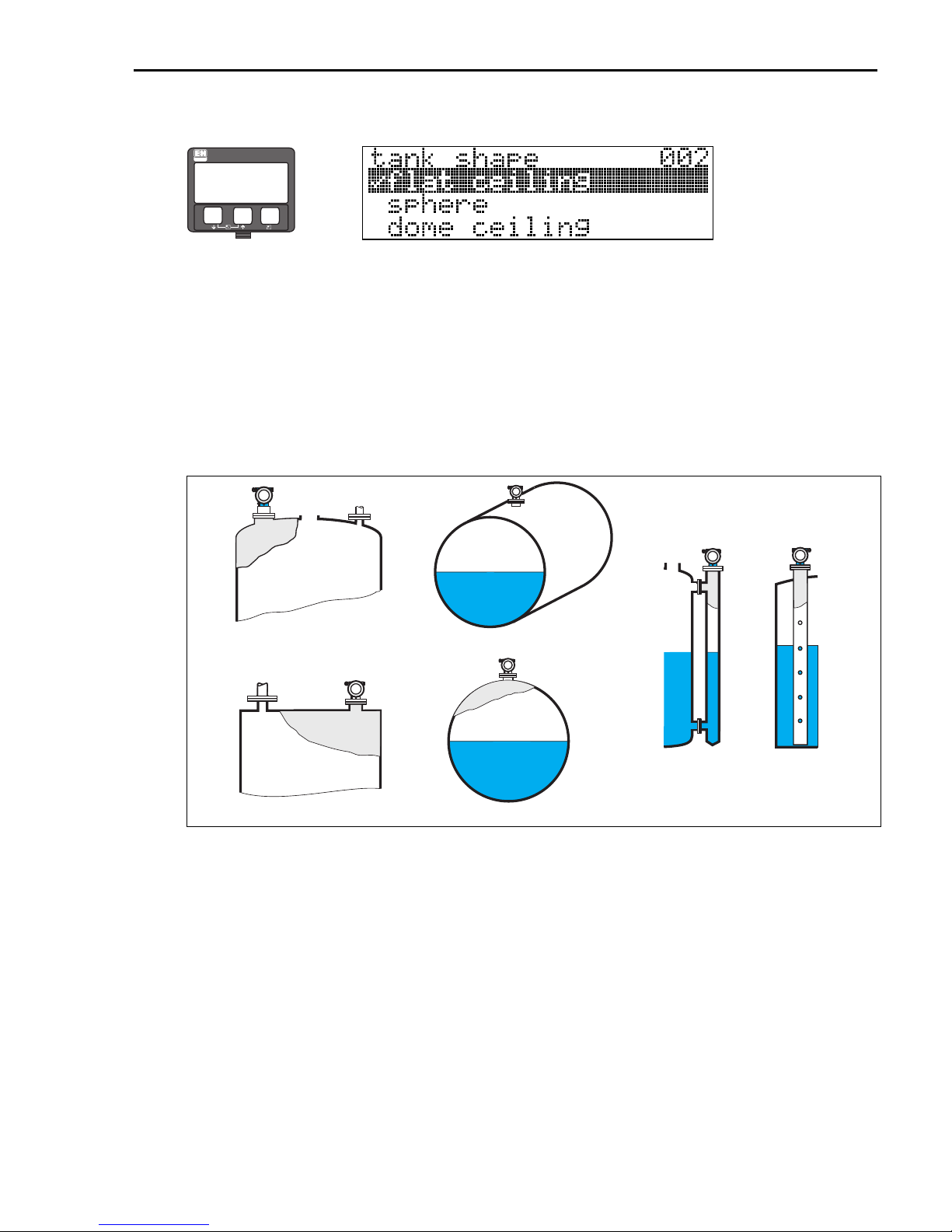
5.4.4 Function "tank shape" (002), liquids only
ENDRESS + HAUSER
–
⇒
+
E
This function is used to select the tank shape.
Selection:
• dome ceiling
• horizontal cyl
•bypass
• stilling well
• flat ceiling
•sphere
dome ceiling
horizontal cyl
flat ceiling sphere
Endress+Hauser 27
bypass stilling well
L00-FMR2xxxx-14-00-06-en-007
Page 28
Commissioning Micropilot M FMR244 PROFIBUS PA
5.4.5 Function "medium property" (003), liquids only
ENDRESS + HAUSER
–
⇒
+
E
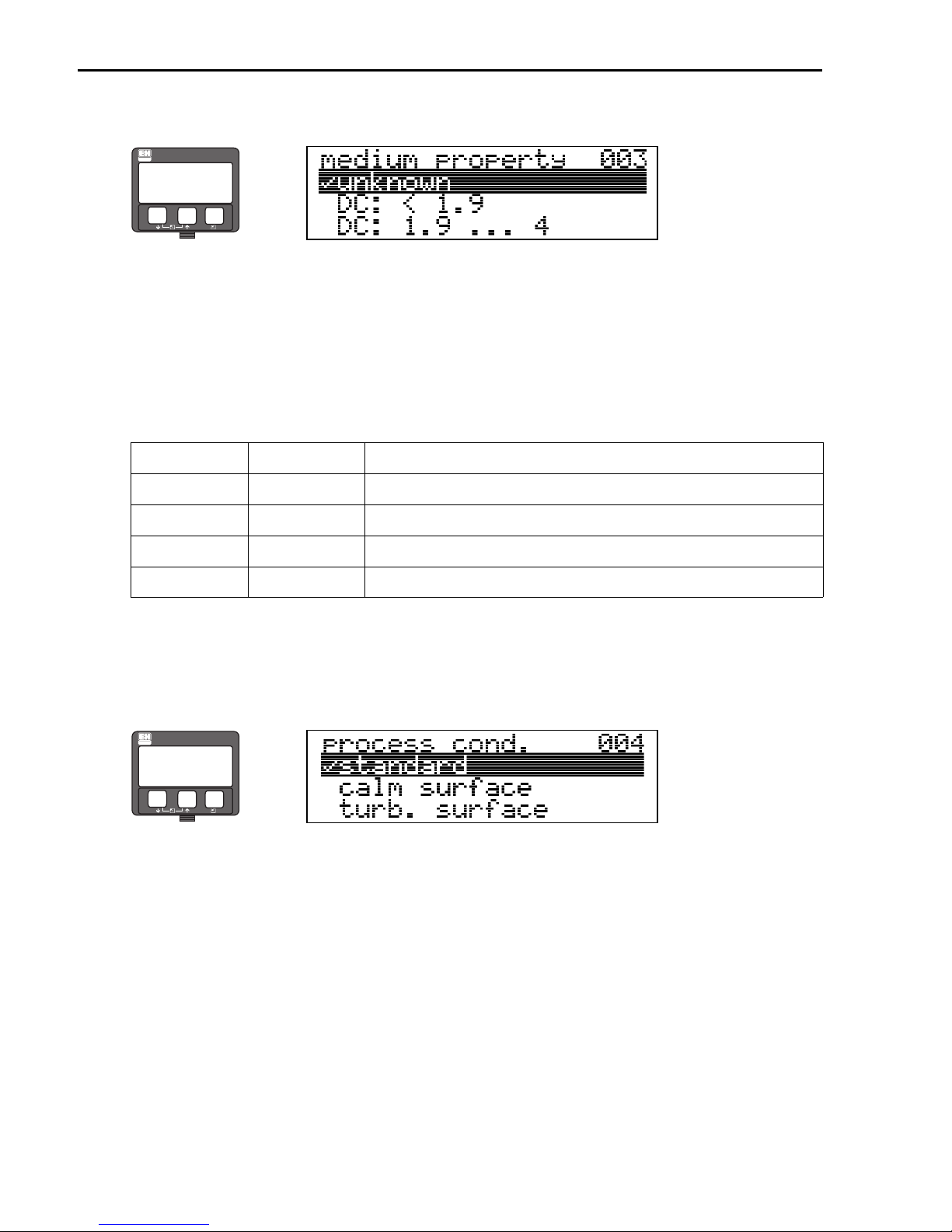
This function is used to select the dielectric constant.
Selection:
• unknown
• DC: < 1.9
• DC: 1.9 ... 4
• DC: 4 ... 10
• DC: > 10
Media group DC (εr) Examples
A < 1.9 non-conducting liquids, e.g. liquefied gas
B 1.9 to 4 non-conducting liquids, e.g. benzene, oil, toluene ...
C 4 to 10 e.g. concentrated acids, organic solvents, esters, aniline, alcohol, acetone, ...
D > 10 conducting liquids, e.g. aqueous solutions, dilute acids and alkalis
1) Treat Ammonia NH3 as a medium of group A, i.e. use FMR230 in a stilling well.
1)
5.4.6 Function "process cond." (004) , liquids only
ENDRESS + HAUSER
⇒
–
+
E
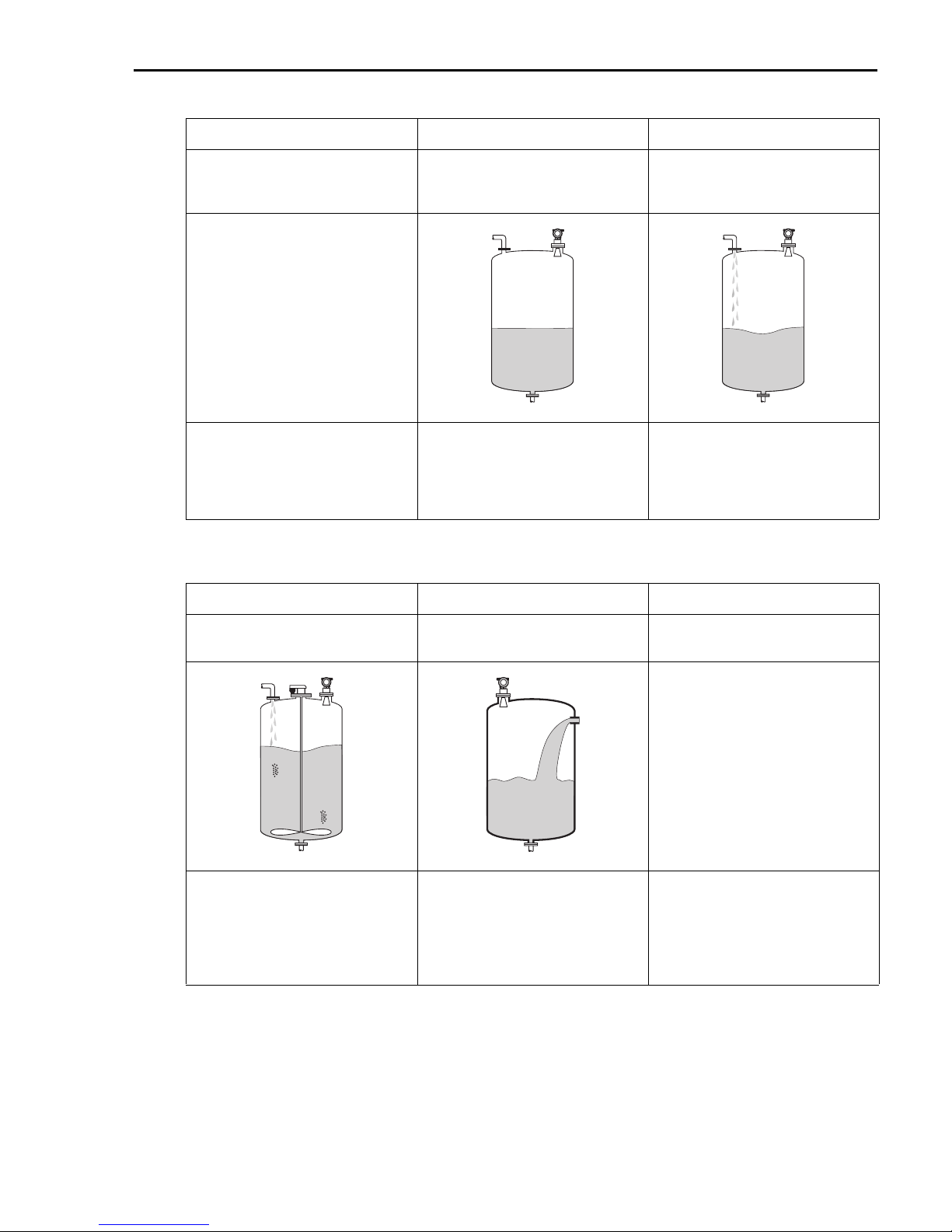
This function is used to select the process conditions.
Selection:
• standard
• calm surface
•turb. surface
•agitator
• fast change
• test: no filter
28 Endress+Hauser
Page 29
Micropilot M FMR244 PROFIBUS PA Commissioning
standard calm surface turb. surface
For all applications that do not fit into
any of the following groups.
The filter and output damping are set
to average values.
agitator fast change test: no filter
Storage tanks with immersion tube or
bottom filling.
a0006540 a0006538
The averaging filters and output
damping are set to high values.
→ steady meas. value
→ precise measurement
→ slower reaction time
Storage / buffer tanks with rough
surface due to free filling or mixer
nozzles.
Special filters to smooth the input
signals are emphasised.
→ smoothed meas. value
→ medium fast reaction time
Agitated surfaces (with possible
vortex) due to agitators.
Special filters to smooth the input
signals are set to high values.
→ smoothed meas. value
→ medium fast reaction time
→ minimization of effects
by agitator blades.
Rapid change of level, particularly in
small tanks.
a0006537 a0006539
The averaging filters are set to low
values. The output damping is set to 0.
→ rapid reaction time
→ possibly unsteady meas. value
All filters can be switched off for
service / diagnostic purposes.
All filters off.
Endress+Hauser 29
Page 30
Commissioning Micropilot M FMR244 PROFIBUS PA
5.4.7 Function "vessel / silo" (00A), solids only
ENDRESS + HAUSER
–
+
E
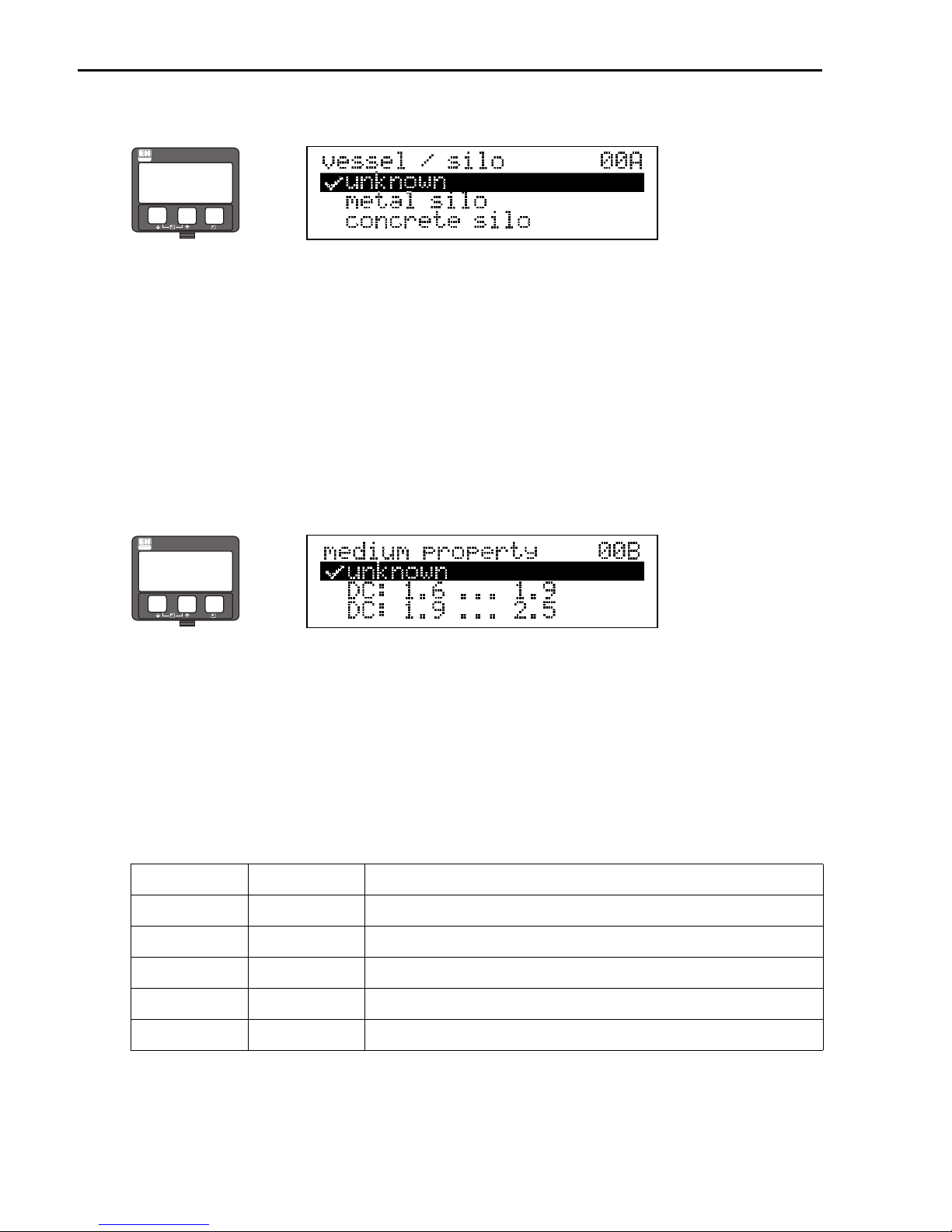
This function is used to select the vessel / silo.
Selection:
• unknown
• metal silo
• concrete silo
• bin / bunker
•dome
• stockpile
• conveyor belt
5.4.8 Function "medium property" (00B), solids only
ENDRESS + HAUSER
⇒
–
+
E
This function is used to select the dielectric constant.
⇒
Selection:
• unknown
• DC: 1.6 ... 1.9
• DC: 1.9 ... 2.5
• DC: 2.5 ... 4
• DC: 4 ... 7
• DC: > 7
Media group DC (εr) Examples
A 1.6 to 1.9 Plastic granulate, White lime, special cement, sugar
B 1.9 to 2.5 Portland cement, plaster
C 2.5 to 4 Grain, seeds, ground stones, sand
D 4 to 7 naturally moist (ground) stones, ores, salt
E > 7 Metallic powder, carbon black, coal
The respective lower group applies for very loose or loosened bulk solids.
30 Endress+Hauser
Page 31
Micropilot M FMR244 PROFIBUS PA Commissioning
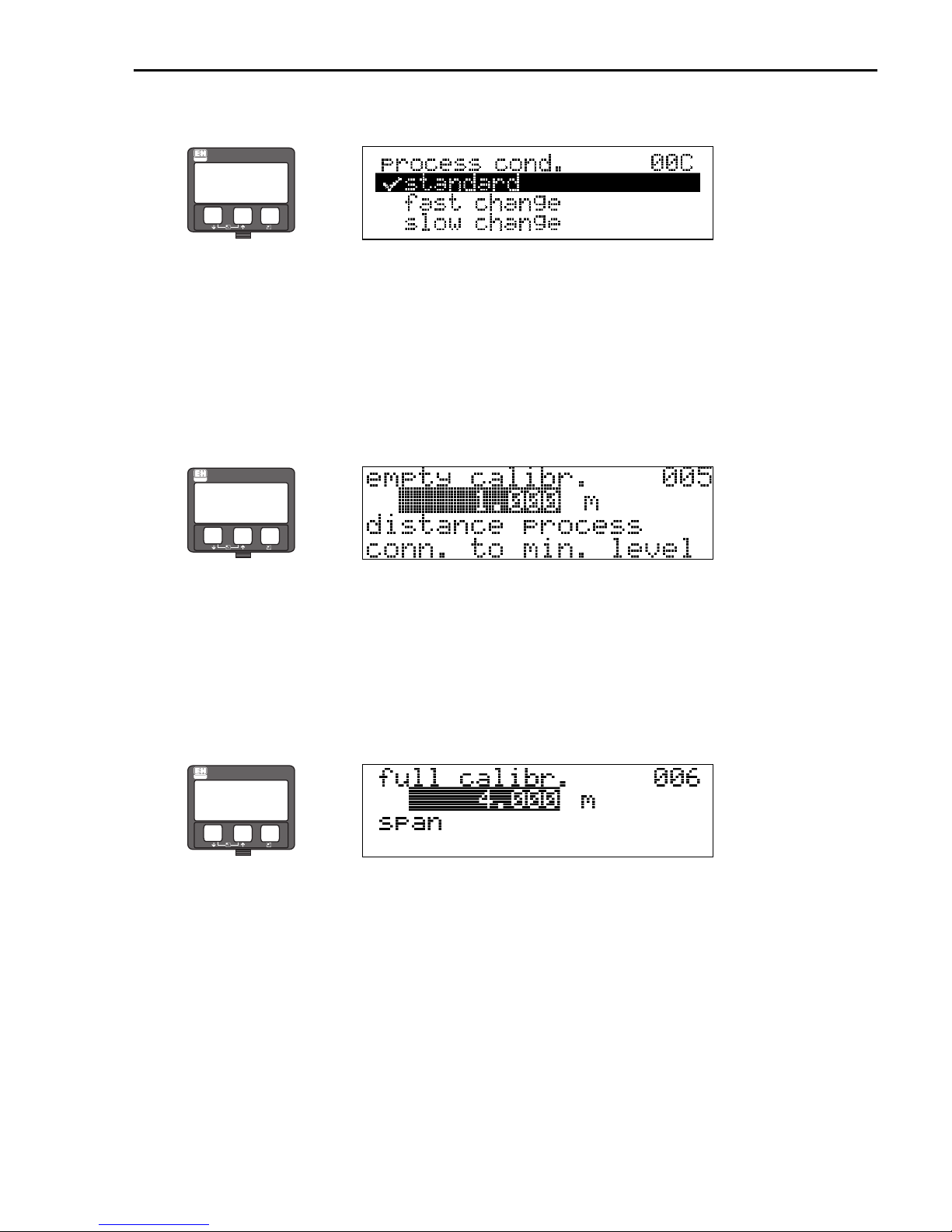
5.4.9 Function "process cond." (00C), solids only
ENDRESS + HAUSER
–
+
E
This function is used to select the process conditions.
Selection:
• standard
• fast change
• slow change
• test: no filter
5.4.10 Function "empty calibr." (005)
ENDRESS + HAUSER
⇒
–
+
E
This function is used to enter the distance from the flange (reference point of the measurement)
to the minimum level (=zero) (→ ä 24).
Caution!
"
For dish bottoms or conical outlets, the zero point should be no lower than the point at which
the radar beam hits the bottom of the tank.
⇒
!
5.4.11 Function "full calibr." (006)
ENDRESS + HAUSER
⇒
–
+
E
This function is used to enter the distance from the minimum level to the maximum level
(=span).
Note!
•If bypass or stilling well was selected in the "tank shape" (002) function, the pipe
diameter is requested in the following step.
• For FMR244, the end of
to the tip of the antenna, especially if there is development of condensate.
measuring range should not be chosen closer than 150 mm (5.91 in)
Endress+Hauser 31
Page 32
Commissioning Micropilot M FMR244 PROFIBUS PA
5.4.12 Function "pipe diameter" (007)
ENDRESS + HAUSER
–
+
E
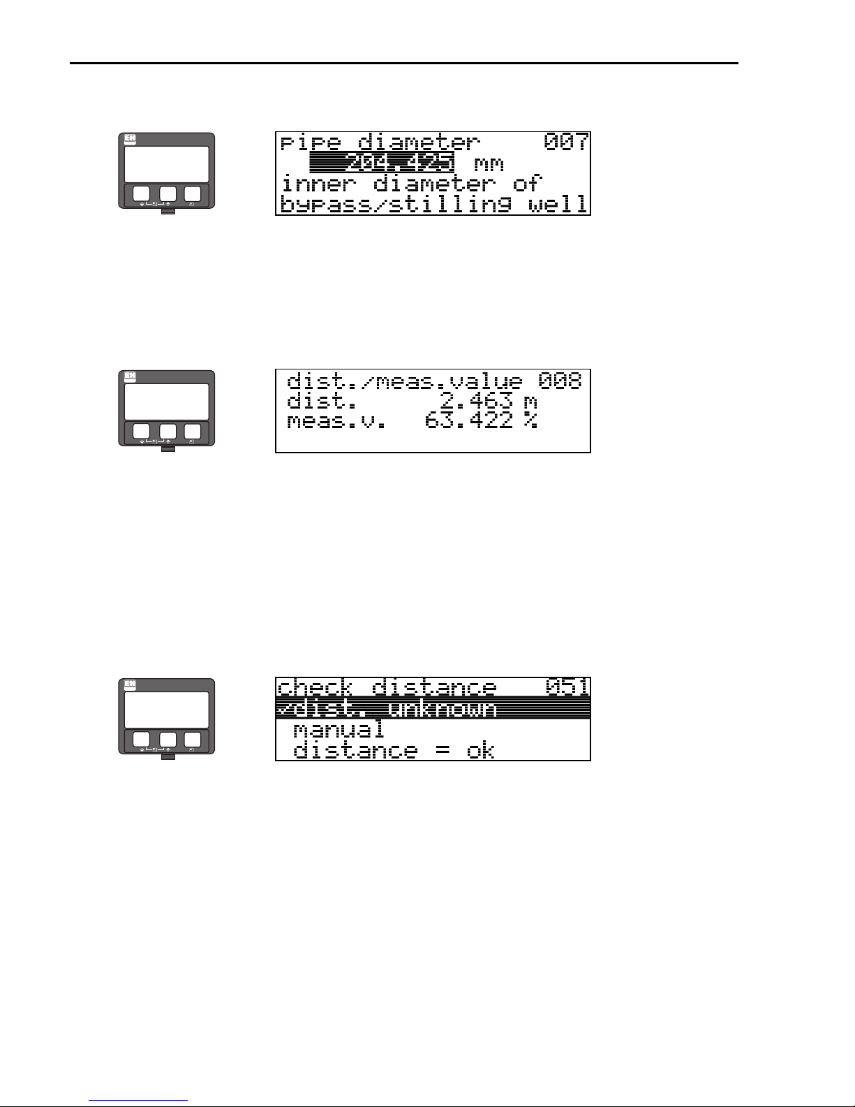
This function is used to enter the pipe diameter of the stilling well or bypass pipe.Microwaves
propagate more slowly in pipes than in free space. This effect depends on the inside diameter of
the pipe and is automatically taken into account by the Micropilot. It is only necessary to enter
the pipe diameter for applications in a bypass or stilling well.
5.4.13 Function "dist./meas.value" (008)
ENDRESS + HAUSER
⇒
–
+
E
The distance measured from the reference point to the product surface and the level calculated
with the aid of the empty adjustment are displayed. Check whether the values correspond to the
actual meas. value or the actual distance. The following cases can occur:
• Distance correct - level correct È continue with the next function "check distance" (051)
• Distance correct - level incorrect È Check "empty calibr." (005)
• Distance incorrect - level incorrect È continue with the next function
"check distance" (051).
⇒
5.4.14 Function "check distance" (051)
ENDRESS + HAUSER
⇒
–
+
E
This function triggers the mapping of interference echoes. To do so, the measured distance must
be compared with the actual distance to the product surface. The following options are available
for selection:
Selection:
• distance = ok
• dist. too small
• dist. too big
• dist. unknown
• manual
32 Endress+Hauser
Page 33
Micropilot M FMR244 PROFIBUS PA Commissioning
L00-FMR2xxxx-14-00-06-en-010
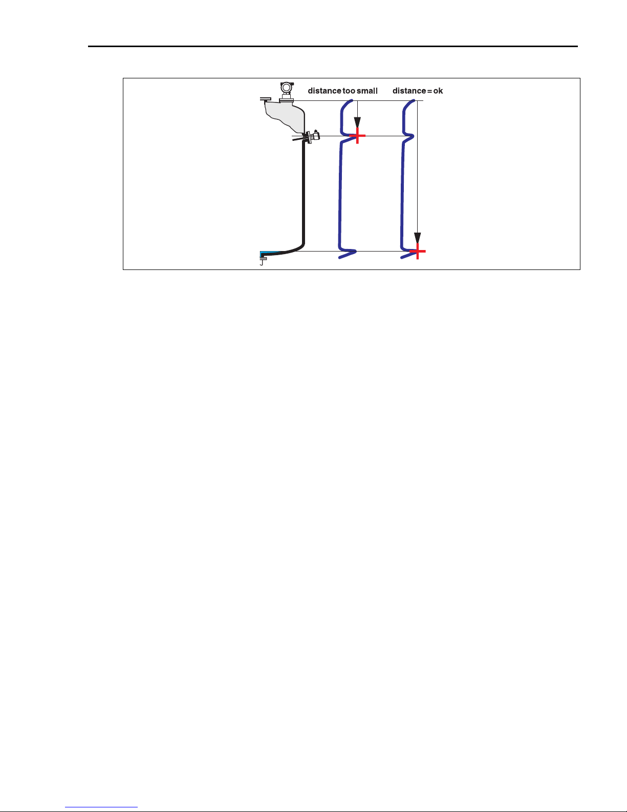
distance = ok
• mapping is carried out up to the currently measured echo
•
The range to be suppressed is suggested in the
"range of mapping" (052)
function
!
"
Note!
Anyway, it is wise to carry out a mapping even in this case.
dist. too small
• At the moment, an interference is being evaluated
• Therefore, a mapping is carried out including the presently measured echoes
The range to be suppressed is suggested in the
•
dist. too big
• This error cannot be remedied by interference echo mapping
• Check the application parameters (002), (003), (004) and "empty calibr." (005)
dist. unknown
If the actual distance is not known, no mapping can be carried out.
manual
A mapping is also possible by manual entry of the range to be suppressed. This entry is made in
the "range of mapping" (052) function.
Caution!
The range of mapping must end 0,5 m (1.6 ft) before the echo of the actual level. For an empty
tank, do not enter E, but E - 0,5 m (1.6 ft). If a mapping already exists, it is overwriten up to the
distance specified in "range of mapping" (052). Beyond this value the existing mapping
remains unchanged.
"range of mapping" (052)
function
Endress+Hauser 33
Page 34
Commissioning Micropilot M FMR244 PROFIBUS PA
5.4.15 Function "range of mapping" (052)
ENDRESS + HAUSER
–
+
E
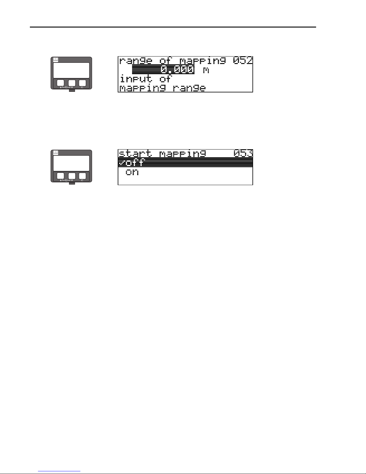
This function displays the suggested range of mapping. The reference point is always the
reference point of the measurement (→ ä 24). This value can be edited by the operator. For
manual mapping, the default value is: 0 m.
5.4.16 Function "start mapping" (053)
ENDRESS + HAUSER
⇒
–
+
E
This function is used to start the interference echo mapping up to the distance given in "range
of mapping" (052).
Selection:
• off: no mapping is carried out
• on: mapping is started
During the mapping process the message "record mapping" is displayed.
⇒
Caution!
"
A mapping will be recorded only, if the device is not in alarm-state.
34 Endress+Hauser
Page 35
Micropilot M FMR244 PROFIBUS PA Commissioning
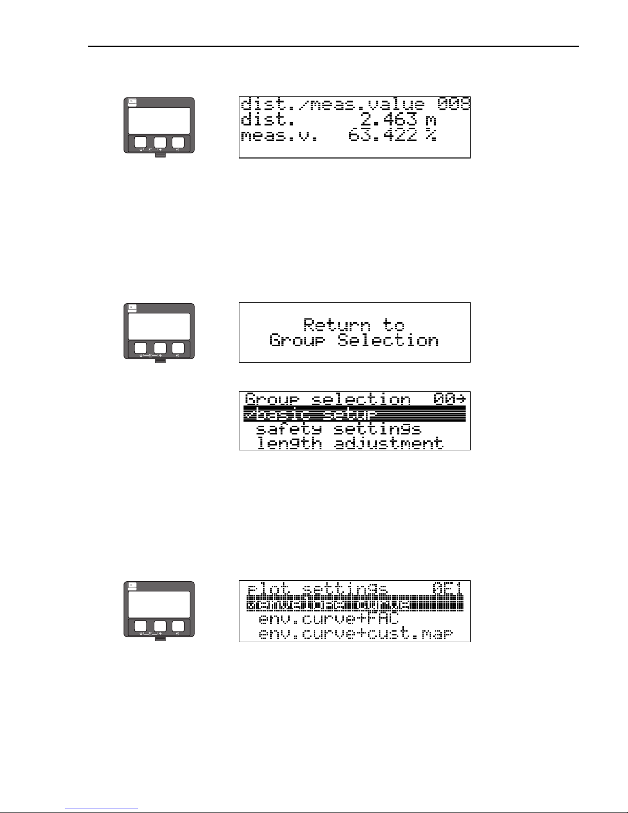
5.4.17 Function "dist./meas.value" (008)
ENDRESS + HAUSER
–
+
E
The distance measured from the reference point to the product surface and the level calculated
with the aid of the empty adjustment are displayed. Check whether the values correspond to the
actual meas. value or the actual distance. The following cases can occur:
• Distance correct - level correct È continue with the next function "check distance" (051)
• Distance correct - level incorrect È Check "empty calibr." (005)
• Distance incorrect - level incorrect È continue with the next function
"check distance" (051).
ENDRESS + HAUSER
⇒
–
+
E
⇒
⇓
After 3 s, the following
message appears
5.5 Envelope curve with the instrument display
After the basic setup, an evaluation of the measurement with the aid of the envelope curve
("envelope curve" (0E) function group) is recommended.
5.5.1 Function "plot settings" (0E1)
ENDRESS + HAUSER
⇒
–
+
E
Select which information will be displayed in the LCD:
• envelope curve
• env.curve+FAC (on FAC see BA291F/00/EN)
• env.curve+cust.map (i.e. customer tank map is also displayed)
Endress+Hauser 35
Page 36

Commissioning Micropilot M FMR244 PROFIBUS PA
5.5.2 Function "recording curve" (0E2)
This function defines whether the envelope curve is read as a
• single curve or
• cyclic
ENDRESS + HAUSER
!
–
⇒
+
E
Note!
• If the cyclical envelope curve is active in the display, the measured value is refreshed in a
slower cycle time. It is therefore recommended to exit the envelope curve display after
optimising the measuring point.
•An orientation of the Micropilot can help to optimise measurement in applications with very
weak level echos or strong interference echos by increasing the useful echo/reducing the
interference echo (see BA249F/00/EN, Chapter "Orientation of the Micropilot").
5.5.3 Function "envelope curve display" (0E3)
The envelope curve is displayed in this function. You can use it to obtain the following
information:
full calibr.
quality of
evaluated echo
evaluated echo
is marked
envelope curve
only
envelope curve and
interference echo
suppression (map)
minimum distance
of the plot
map
interference echo
distance of
evaluated echo
maximum distance
of the plot
level echo
empty calibr.
L00-FMUxxxx-07-00-00-en-003
36 Endress+Hauser
Page 37

Micropilot M FMR244 PROFIBUS PA Commissioning
Endress+Hauser 37
Page 38

Commissioning Micropilot M FMR244 PROFIBUS PA
38 Endress+Hauser
Page 39

Micropilot M FMR244 PROFIBUS PA Commissioning
Endress+Hauser 39
Page 40

KA1010F/00/EN/12.09
71030600
CCS/FM+SGML 6.0
www.endress.com/worldwide
71030600
 Loading...