

Page 1
BA229F/00/ae/06.07
5200
9950
Valid as of software version:
01.04.00
Operating Instructions
Micropilot M FMR231
Level-Radar
9
Page 2
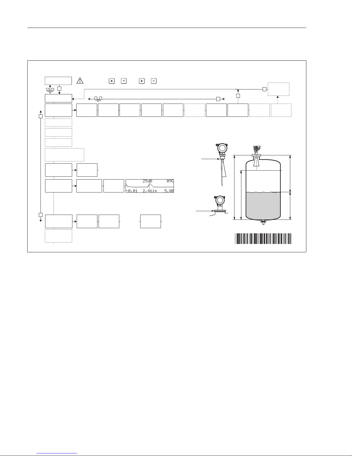
Brief operating instructions Micropilot M FMR231 with FOUNDATION Fieldbus
2 Endress+Hauser
Brief operating instructions
L00-FMR2xxxx-19-00-00-en-039
!
Note!
This operating manual explains the installation and initial start-up for the level transmitter. All
functions that are required for a typical measuring task are taken into account here. In addition, the
Micropilot M provides many other functions that are not included in this operating manual, such as
optimising the measuring point and converting the measured values.
An overview of all device functions can be found on Page 96.
The operating manual BA 221F/00/en "Description of the instrument functions for Micropilot M"
provides an extensive description of all device functions, which can be found on the enclosed
CD-ROM.
E
+
-
+
E
+
-
F
L
D
E
E
E
-
… …
… …
KA159F/00/a2/08.06
52006292
52006292
… …
Micropilot M FMR230, FMR231 - Brief operating instructions
- dome
ceiling
- horizontal
cyl.
- bypass
…
- unknown
- DC: <1.9
- DC: 1.9 … 4
-DC:4…10
- DC: >10
- standard
- calm
surface
- add. agitator
…
input E
(see sketch)
input F
(see sketch)
only for
bypass +
stilling well
-ok
- too small
- too big
- unknown
- manual
displayed
(see sketch)
D and L are
confirm
or specify
range
suggestion
000
measured value
Group
selection
00
basic setup
01
safety settings
0C
system
parameter
09
display
0E
envelope curve
04
linearisation
05
extended calibr.
06
output (HART, FF)
profibus param.(PA)
092
language
0A
diagnostics
0A0
present
error
002
tank shape
004
process
cond.
005
empty
calibr.
006
full
calibr.
007
pipe
diameter
008
dist./
meas value
051
check
distance
003
medium
cond.
052
range of
mapping
053
start
mapping
008
dist./
meas value
flange:
reference point
of measurement
- envel. curve
- incl. FAC
- incl. cust. map
- single curve
- cyclic
= 100: unlocked
100: locked
= 2457: unlocked
2457: locked
0E1
plot settings
0E2
recording
curve
0A1
previous
error
0A4
unlock
parameter
threaded connection:
reference point of
measurement
HART
PA, FF
}
}
Contrast: + or +
Page 3

Micropilot M FMR231 with FOUNDATION Fieldbus Table of contents
Endress+Hauser 3
Table of contents
1 Safety instructions . . . . . . . . . . . . . . . . 4
1.1 Designated use . . . . . . . . . . . . . . . . . . . . . . . . . . . . 4
1.2 Installation, commissioning and operation . . . . . . . . 4
1.3 Operational safety . . . . . . . . . . . . . . . . . . . . . . . . . . 4
1.4 Notes on safety conventions and symbols . . . . . . . . . 5
2 Identification . . . . . . . . . . . . . . . . . . . . 6
2.1 Device designation . . . . . . . . . . . . . . . . . . . . . . . . . 6
2.2 Scope of delivery . . . . . . . . . . . . . . . . . . . . . . . . . . . 9
2.3 Certificates and approvals . . . . . . . . . . . . . . . . . . . . 9
2.4 Registered trademarks . . . . . . . . . . . . . . . . . . . . . . . 9
3 Mounting . . . . . . . . . . . . . . . . . . . . . . 10
3.1 Quick installation guide . . . . . . . . . . . . . . . . . . . . . 10
3.2 Incoming acceptance, transport, storage . . . . . . . . . 11
3.3 Installation conditions . . . . . . . . . . . . . . . . . . . . . . 12
3.4 Installation instructions . . . . . . . . . . . . . . . . . . . . . 20
3.5 Post-installation check . . . . . . . . . . . . . . . . . . . . . . 22
4 Wiring . . . . . . . . . . . . . . . . . . . . . . . . 23
4.1 Quick wiring guide . . . . . . . . . . . . . . . . . . . . . . . . 23
4.2 Connecting the measuring unit . . . . . . . . . . . . . . . 26
4.3 Recommended connection . . . . . . . . . . . . . . . . . . 26
4.4 Degree of protection . . . . . . . . . . . . . . . . . . . . . . . 26
4.5 Post-connection check . . . . . . . . . . . . . . . . . . . . . . 26
5 Operation . . . . . . . . . . . . . . . . . . . . . . 27
5.1 Operating options . . . . . . . . . . . . . . . . . . . . . . . . . 27
5.2 Operation with the display and operating
module VU331 . . . . . . . . . . . . . . . . . . . . . . . . . . . 29
5.3 Operation with an Endress+Hauser
operating program . . . . . . . . . . . . . . . . . . . . . . . . . 34
5.4 Operation with a FOUNDATION Fieldbus
configuration program . . . . . . . . . . . . . . . . . . . . . . 37
5.5 Operation with the handheld terminal
DXR375/FC375 . . . . . . . . . . . . . . . . . . . . . . . . . . 39
6 Commissioning. . . . . . . . . . . . . . . . . . 41
6.1 Function check . . . . . . . . . . . . . . . . . . . . . . . . . . . 41
6.2 Unlocking the device . . . . . . . . . . . . . . . . . . . . . . . 41
6.3 Resetting the device . . . . . . . . . . . . . . . . . . . . . . . 43
6.4 Commissioning by the display and operatig
module VU331 . . . . . . . . . . . . . . . . . . . . . . . . . . . 45
6.5 Basic Setup with the Endress+Hauser
operating program . . . . . . . . . . . . . . . . . . . . . . . . . 58
6.6 Commissioning with a FOUNDATION Fieldbus
configuration tool . . . . . . . . . . . . . . . . . . . . . . . . . 62
6.7 Commissioning with the handheld terminal
DXR375/FC375 . . . . . . . . . . . . . . . . . . . . . . . . . . 67
7 Maintenance . . . . . . . . . . . . . . . . . . . . 68
8 Accessories . . . . . . . . . . . . . . . . . . . . . 69
9 Trouble-shooting . . . . . . . . . . . . . . . . . 72
9.1 Trouble-shooting instructions . . . . . . . . . . . . . . . . . 72
9.2 System error messages . . . . . . . . . . . . . . . . . . . . . . 73
9.3 Application errors . . . . . . . . . . . . . . . . . . . . . . . . . 77
9.4 Orientation of the Micropilot . . . . . . . . . . . . . . . . . 79
9.5 Spare parts . . . . . . . . . . . . . . . . . . . . . . . . . . . . . . . 81
9.6 Return . . . . . . . . . . . . . . . . . . . . . . . . . . . . . . . . . . 86
9.7 Disposal . . . . . . . . . . . . . . . . . . . . . . . . . . . . . . . . . 86
9.8 Software history . . . . . . . . . . . . . . . . . . . . . . . . . . . 86
9.9 Contact addresses of Endress+Hauser . . . . . . . . . . . 86
10 Technical data . . . . . . . . . . . . . . . . . . . 87
10.1 Additional technical data . . . . . . . . . . . . . . . . . . . . 87
11 Appendix. . . . . . . . . . . . . . . . . . . . . . . 96
11.1 Operating menu . . . . . . . . . . . . . . . . . . . . . . . . . . 96
11.2 Block model of the Micropilot M . . . . . . . . . . . . . . 98
11.3 Resource block . . . . . . . . . . . . . . . . . . . . . . . . . . . 99
11.4 Sensor block . . . . . . . . . . . . . . . . . . . . . . . . . . . . 100
11.5 Diagnostic Block . . . . . . . . . . . . . . . . . . . . . . . . . 103
11.6 Display Block . . . . . . . . . . . . . . . . . . . . . . . . . . . . 104
11.7 Analog input block . . . . . . . . . . . . . . . . . . . . . . . . 105
11.8 List of start indices . . . . . . . . . . . . . . . . . . . . . . . . 109
11.9 Patents . . . . . . . . . . . . . . . . . . . . . . . . . . . . . . . . 110
Index . . . . . . . . . . . . . . . . . . . . . . . . . . . . . 111
Page 4

Safety instructions Micropilot M FMR231 with FOUNDATION Fieldbus
4 Endress+Hauser
1 Safety instructions
1.1 Designated use
The Micropilot M FMR 231 is a compact radar level transmitter for the continuous, contactless
measurement of liquids, pastes and sludge. The device can also be freely mounted outside closed
metal vessels because of its operating frequency of about 6 GHz and a maximum radiated pulsed
energy of 1mW (average power output 1 μW). Operation is completely harmless to humans and
animals.
1.2 Installation, commissioning and operation
The Micropilot M has been designed to operate safely in accordance with current technical, safety
and EU standards. If installed incorrectly or used for applications for which it is not intended,
however, it is possible that application-related dangers may arise, e.g. product overflow due to
incorrect installation or calibration. For this reason, the instrument must be installed, connected,
operated and maintained according to the instructions in this manual: personnel must be authorised
and suitably qualified. The manual must have been read and understood, and the instructions
followed. Modifications and repairs to the device are permissible only when they are expressly
approved in the manual.
1.3 Operational safety
1.3.1 Hazardous areas
Measuring systems for use in hazardous environments are accompanied by separate "Ex
documentation", which is an integral part of this Operating Manual. Strict compliance with the
installation instructions and ratings as stated in this supplementary documentation is mandatory.
• Ensure that all personnel are suitably qualified.
• Observe the specifications in the certificate as well as national and local standards and regulations.
1.3.2 FCC approval
This device complies with part 15 of the FCC Rules. Operation is subject to the following two
conditions: (1) This device may not cause harmful interference, and (2) this device must accept any
interference received, including interference that may cause
undesired operation.
"
Caution!
Changes or modifications not expressly approved by the part responsible for
compliance could void the user’s authority to operate the equipment.
Page 5

Micropilot M FMR231 with FOUNDATION Fieldbus Safety instructions
Endress+Hauser 5
1.4 Notes on safety conventions and symbols
In order to highlight safety-relevant or alternative operating procedures in the manual, the following
conventions have been used, each indicated by a corresponding symbol in the margin.
Safety conventions
#
Warning!
A warning highlights actions or procedures which, if not performed correctly, will lead to personal
injury, a safety hazard or destruction of the instrument
"
Caution!
Caution highlights actions or procedures which, if not performed correctly, may lead to personal
injury or incorrect functioning of the instrument
!
Note!
A note highlights actions or procedures which, if not performed correctly, may indirectly affect
operation or may lead to an instrument response which is not planned
Explosion protection
0
Device certified for use in explosion hazardous area
If the device has this symbol embossed on its name plate it can be installed in an explosion hazardous
area
-
Explosion hazardous area
Symbol used in drawings to indicate explosion hazardous areas. Devices located in and wiring
entering areas with the designation “explosion hazardous areas” must conform with the stated type
of protection.
.
Safe area (non-explosion hazardous area)
Symbol used in drawings to indicate, if necessary, non-explosion hazardous areas. Devices located in
safe areas still require a certificate if their outputs run into explosion hazardous areas
Electrical symbols
%
Direct voltage
A terminal to which or from which a direct current or voltage may be applied or supplied
&
Alternating voltage
A terminal to which or from which an alternating (sine-wave) current or voltage may be applied or
supplied
)
Grounded terminal
A grounded terminal, which as far as the operator is concerned, is already grounded by means of an
earth grounding system
*
Protective grounding (earth) terminal
A terminal which must be connected to earth ground prior to making any other connection to the
equipment
+
Equipotential connection (earth bonding)
A connection made to the plant grounding system which may be of type e.g. neutral star or
equipotential line according to national or company practice
Temperature resistance of the connection cables
States, that the connection cables must be resistant to a temperature of at least 85 °C.
t >85°C
Page 6

Identification Micropilot M FMR231 with FOUNDATION Fieldbus
6 Endress+Hauser
2 Identification
2.1 Device designation
2.1.1 Nameplate
The following technical data are given on the instrument nameplate:
L00-FMR2xxxx-18-00-00-en-003
Fig. 1: Information on the nameplate of the Micropilot M with Foundation Fieldbus (example)
2.1.2 Ordering structure
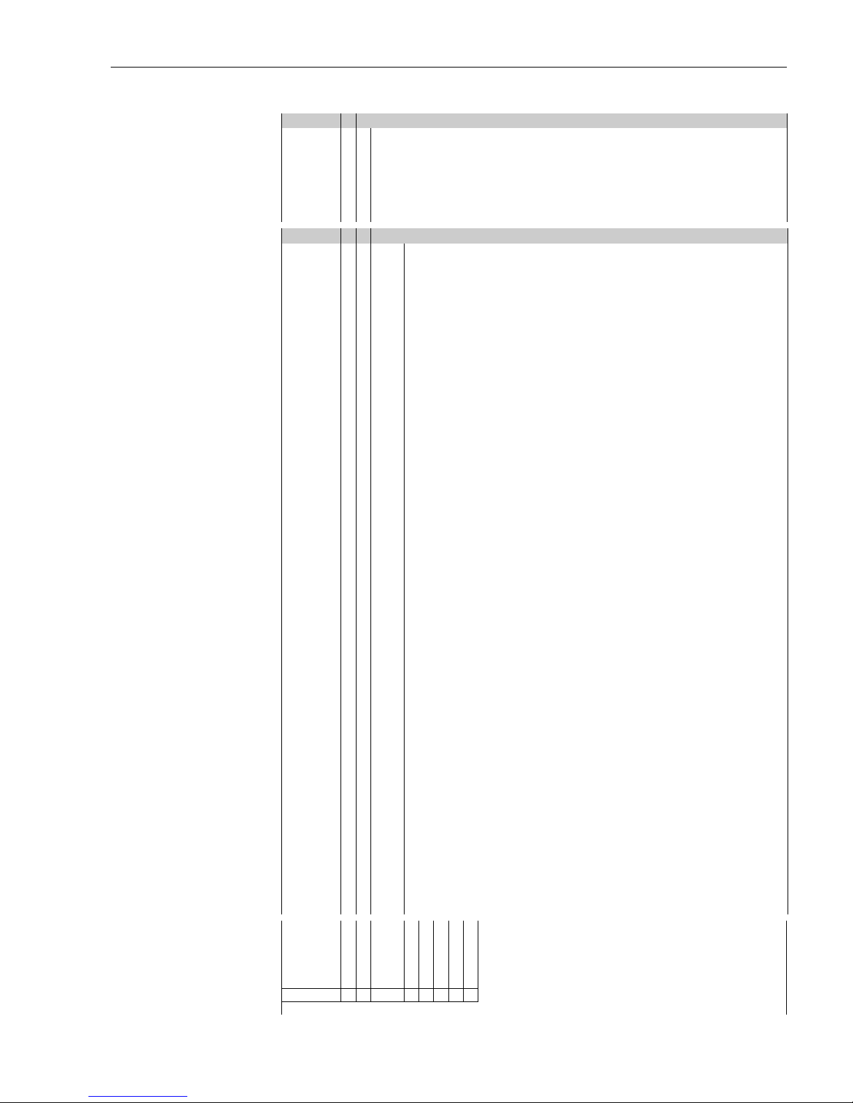
Ordering structure Micropilot M FMR 231
10 Approval:
A Non-hazardous area
F Non-hazardous area, WHG
1 ATEX II 1/2 G EEx ia IIC T6, IECEx Zone 0/1
2 ATEX II 1/2 G EEx ia IIC T6, XA, IECEx Zone 0/1
Note safety instruction (XA) (electrostatic charging)!
6 ATEX II 1/2 G EEx ia IIC T6, WHG, IECEx Zone 0/1
7 ATEX II 1/2 G EEx ia IIC T6, WHG, XA, IECEx Zone 0/1
Note safety instruction (XA) (electrostatic charging)!
3 ATEX II 1/2 G EEx em [ia] IIC T6, IECEx Zone 0/1
8 ATEX II 1/2 G EEx em [ia] IIC T6, WHG, IECEx Zone 0/1
4 ATEX II 1/2 G EEx d [ia] IIC T, IECEx Zone 0/16
G ATEX II 3 G EEx nA II T6, XA,
fully insutalted antenna: Note safety instruction (XA) (electrostatic charging)!
H ATEX II 1/2G EEx ia IIC T6, ATEX II 3D, XA,
fully insutalted antenna: Note safety instruction (XA) (electrostatic charging)!
S FM IS - Cl.I Div.1 Gr. A-D
T FM XP - Cl.I Div.1 Group A-D
N CSA General Purpose
U CSA IS - Cl.I Div.1 Group A-D
V CSA XP - Cl.I Div.1 Group A-D
K TIIS EEx ia IIC T4
L TIIS EEx d [ia] IIC T4
M TIIS EEx d [ia] IIC T1
I NEPSI Ex ia IIC T6
J NEPSI Ex d [ia] IIC T6
R NEPSI Ex nAL IIC T6
Y Special version
FMR 231- Product designation (part 2)
Page 7
Micropilot M FMR231 with FOUNDATION Fieldbus Identification
Endress+Hauser 7
Ordering structure Micropilot M FMR 231 (continued)
20 Antenna; Inactive length:
A PPS antistatic 360mm/14", Viton, 316L; nozzle height max 100mm/4"
B PPS antistatic 510mm/20", Viton, 316L; nozzle height max 250mm/10"
E PTFE 390mm/15", fully insulated; nozzle height max 100mm/4"
F PTFE 540mm/21", fully insulated; nozzle height max 250mm/10"
H PTFE antistatic 390mm/15", fully insul.; nozzle height max 100mm/4"
J PTFE antistatic 540mm/21", fully insul.; nozzle height max 250mm/10"
Y Special version
30 Process connection:
GGJ Thread EN10226 R1-1/2, 316L
GGS Thread EN10226 R1-1/2, PVDF
GNJ Thread ANSI NPT1-1/2, 316L
GNS Thread ANSI NPT1-1/2, PVDF
TEJ Tri-Clamp ISO2852 DN40-51 (2"), 316L
TLJ Tri-Clamp ISO2852 DN70-76.1 (3"), 316L
MFJ DIN11851 DN50 PN40, 316L
HFJ DIN11864-1 A DN50 Tube DIN11850, 316L
BFJ DN50 PN10/16 A, 316L flange EN1092-1 (DIN2527 B)
CFJ DN50 PN10/16 B1, 316L flange EN1092-1 (DIN2527 C)
CFK DN50 PN10/16, PTFE>316L flange EN1092-1 (DIN2527)
BMJ DN80 PN10/16 A, 316L flange EN1092-1 (DIN2527 B)
CMJ DN80 PN10/16 B1, 316L flange EN1092-1 (DIN2527 C)
BNJ DN80 PN25/40 A, 316L flange EN1092-1 (DIN2527 B)
CNJ DN80 PN25/40 B1, 316L flange EN1092-1 (DIN2527 C)
CMK DN80 PN10/16, PTFE>316L flange EN1092-1 (DIN2527)
BQJ DN100 PN10/16 A, 316L flange EN1092-1 (DIN2527 B)
CQJ DN100 PN10/16 B1, 316L flange EN1092-1 (DIN2527 C)
CQK DN100 PN10/16, PTFE>316L flange EN1092-1 (DIN2527)
BWJ DN150 PN10/16 A, 316L flange EN1092-1 (DIN2527 B)
CWJ DN150 PN10/16 B1, 316L flange EN1092-1 (DIN2527 C)
CWK DN150 PN10/16, PTFE(black)>316L flange EN1092-1 (DIN2527)
PTFE(black) = conductive cladding
AEJ 2" 150lbs RF, 316/316L flange ANSI B16.5
AEK 2" 150lbs, PTFE>316/316L flange ANSI B16.5
ALJ 3" 150lbs RF, 316/316L flange ANSI B16.5
AMJ 3" 300lbs RF, 316/316L flange ANSI B16.5
ALK 3" 150lbs, PTFE>316/316L flange ANSI B16.5
APJ 4" 150lbs RF, 316/316L flange ANSI B16.5
AQJ 4" 300lbs RF, 316/316L flange ANSI B16.5
APK 4" 150lbs, PTFE>316/316L flange ANSI B16.5
AVJ 6" 150lbs RF, 316/316L flange ANSI B16.5
AVK 6" 150lbs, PTFE(black)>316/316L flange ANSI B16.5
PTFE(black) = conductive cladding
KEJ 10K 50A RF, 316L flange JIS B2220
KEK 10K 50A, PTFE>316L flange JIS B2220
KLJ 10K 80A RF, 316L flange JIS B2220
KLK 10K 80A, PTFE>316L flange JIS B2220
KPJ 10K 100A RF, 316L flange JIS B2220
KPK 10K 100A, PTFE>316L flange JIS B2220
KVJ 10K 150A RF, 316L flange JIS B2220
KVK 10K 150A, PTFE(black)>316L flange JIS B2220
PTFE(black) = conductive cladding
YY9 Special version
FMR 231- Product designation (part 1)
Page 8
Identification Micropilot M FMR231 with FOUNDATION Fieldbus
8 Endress+Hauser
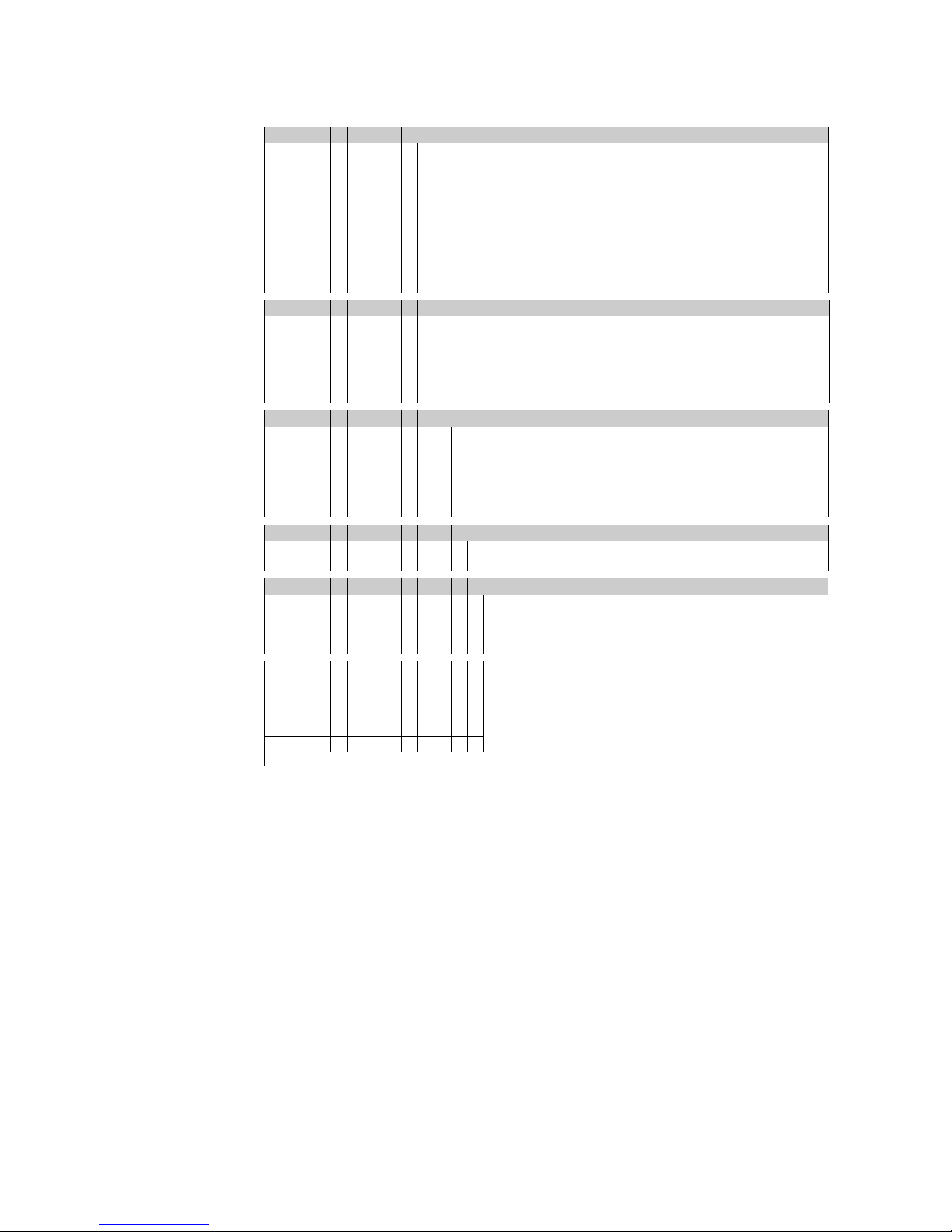
Ordering structure Micropilot M FMR 231 (continued)
40 Output; Operation:
A 4-20mA SIL HART; 4-line display VU331, envelope curve display on site
B 4-20mA SIL HART; w/o display, via communication
K 4-20mA SIL HART; Prepared for FHX40, remote display (Accessory)
C PROFIBUS PA; 4-line display VU331, envelope curve display on site
D PROFIBUS PA; w/o display, via communication
L PROFIBUS PA; Prepared for FHX40, remote display (Accessory)
E FOUNDATION Fieldbus; 4-line display VU331, envelope curve display on site
F FOUNDATION Fieldbus; w/o display, via communication
M FOUNDATION Fieldbus; Prepared for FHX40, remote display (Accessory)
Y Special version
50 Housing:
A F12 Alu, coated IP65 NEMA4X
B F23 316L IP65 NEMA4X
C T12 Alu, coated IP65 NEMA4X, separate conn. compartment
D T12 Alu, coated IP65 NEMA4X+OVP, separate conn. compartment,
OVP=overvoltage protection
Y Special version
60 Cable entry:
2 Gland M20 (EEx d > thread M20)
3Thread G1/2
4 Thread NPT1/2
5Plug M12
6 Plug 7/8"
9 Special version
70 Gas-tight feed through:
A Not selected
C Selected
80 Additional option:
A Basic version
B EN10204-3.1B (316L wetted parts) Inspection certificate
S GL/ABS/NK marine certificate
Y Special version
FMR 231- Complete product designation
Page 9

Micropilot M FMR231 with FOUNDATION Fieldbus Identification
Endress+Hauser 9
2.2 Scope of delivery
"
Caution!
It is essential to follow the instructions concerning the unpacking, transport and storage of
measuring instruments given in the chapter "Incoming acceptance, transport, storage" on Page 11!
The scope of delivery consists of:
• Assembled instrument
• Endress+Hauser oprating program (on the enclosed CD-ROM
• Accessories (→ Chap. 8)
Accompanying documentation:
• Short manual (basic setup/troubleshooting): housed in the instrument
• Operating manual (this manual)
• Approval documentation: if this is not included in the operating manual.
!
Note!
The operating manual "Description of Instrument Functions" you can be found on the enclosed CDROM.
2.3 Certificates and approvals
CE mark, declaration of conformity
The device is designed to meet state-of-the-art safety requirements, has been tested and left the
factory in a condition in which it is safe to operate. The device complies with the applicable
standards and regulations as listed in the EC declaration of conformity and thus complies with the
statutory requirements of the EG directives. Endress+Hauser confirms the successful testing of the
device by affixing to it the CE mark.
2.4 Registered trademarks
KALREZ®, VITON®, TEFLON
®
Registered trademark of the company, E.I. Du Pont de Nemours & Co., Wilmington, USA
TRI-CLAMP
®
Registered trademark of the company, Ladish & Co., Inc., Kenosha, USA
ToF
®
Registered trademark of the company Endress+Hauser GmbH+Co. KG, Maulburg, Germany
PulseMaster
®
Registered trademark of the company Endress+Hauser GmbH+Co. KG, Maulburg, Germany
PhaseMaster
®
Registered trademark of the company Endress+Hauser GmbH+Co. KG, Maulburg, Germany
FOUNDATION™ Fieldbus
Registered trademark of Fieldbus Foundation Austin, Texas, USA
Page 10
Mounting Micropilot M FMR231 with FOUNDATION Fieldbus
10 Endress+Hauser
3Mounting
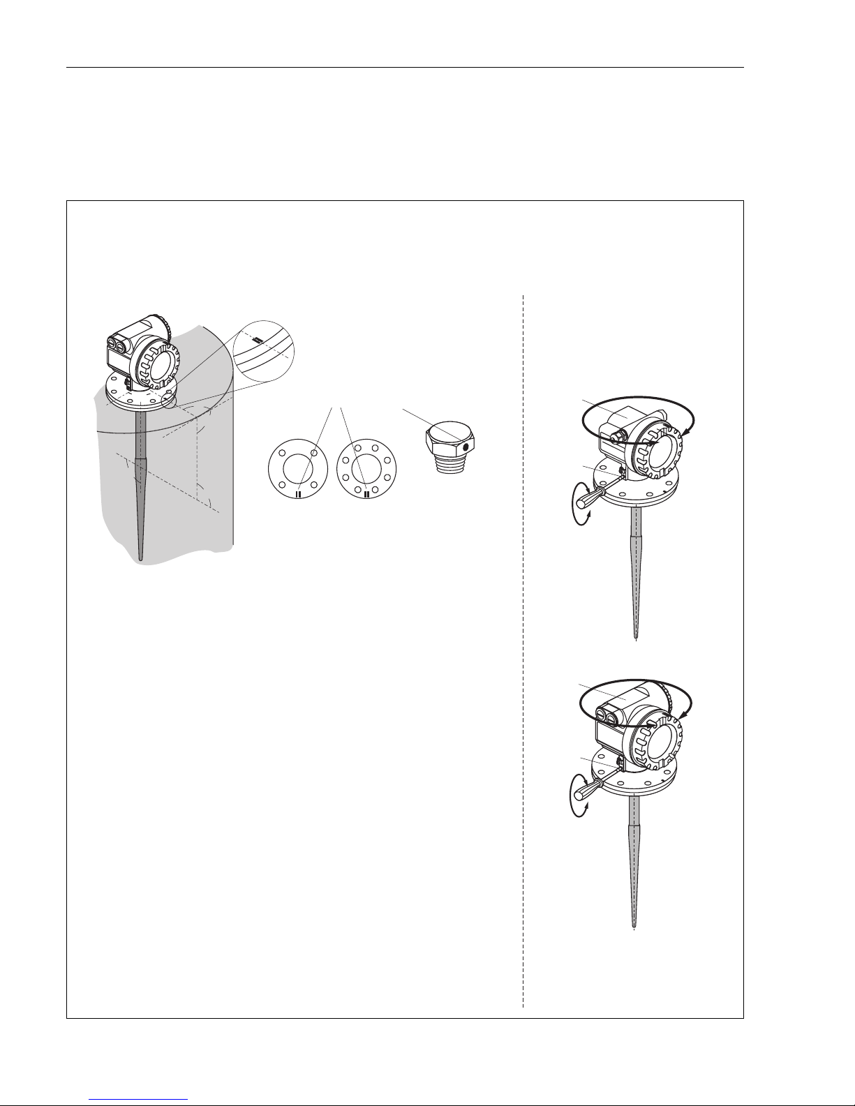
3.1 Quick installation guide
L00-FMR231xx-17-00-00-en-003
1
1
2
2
#
90°
90°
90°
90°
90°
90°
90°
90°
90°
90°
9
DN50
ANSI 2”
DN80…150
ANSI 3…6”
F12/F23 housing
T12 housing
Turn housing
Observe orientation when installing!
Installation in tank (free space):
Mark on process connector facing the nearest tank wall!
The housing can be turned 350°
in order to simplify access to the
display and the terminal compartment
Allen key
4 mm
1½” BSPT (R 1½”)
or
1½ NPT
mark at instrument flange
or threaded boss
Page 11

Micropilot M FMR231 with FOUNDATION Fieldbus Mounting
Endress+Hauser 11
3.2 Incoming acceptance, transport, storage
3.2.1 Incoming acceptance
Check the packing and contents for any signs of damage.
Check the shipment, make sure nothing is missing and that the scope of supply matches your order.
3.2.2 Transport
"
Caution!
Follow the safety instructions and transport conditions for instruments of more than
18 kg.
Do not lift the measuring instrument by its housing in order to transport it.
3.2.3 Storage
Pack the measuring instrument so that is protected against impacts for storage and transport. The
original packing material provides the optimum protection for this.
The permissible storage temperature is -40 °C…+80 °C.
Page 12
Mounting Micropilot M FMR231 with FOUNDATION Fieldbus
12 Endress+Hauser
3.3 Installation conditions
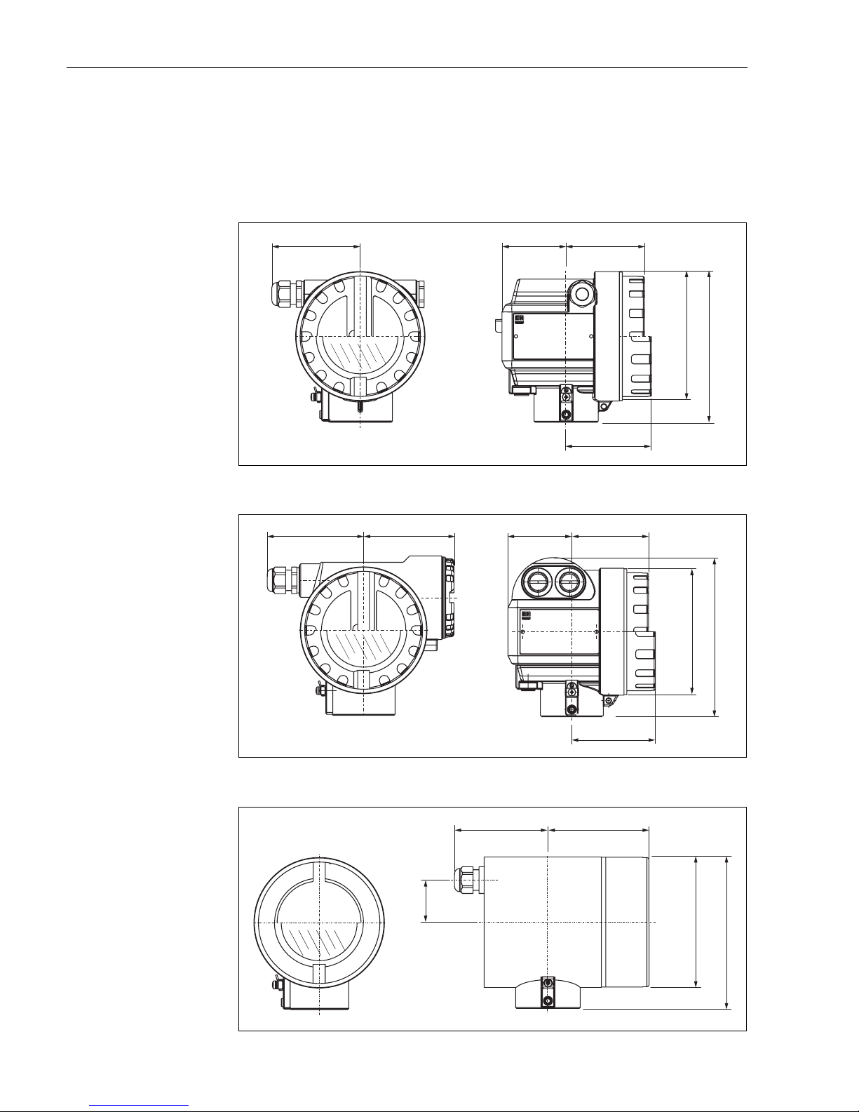
3.3.1 Dimensions
Housing dimensions
L00-F12xxxx-06-00-00-en-001
L00-T12xxxx-06-00-00-en-001
L00-F23xxxx-06-00-00-en-001
ENDRESS+HAUSER
65
78
max. 110
85
150
Ø 129
(Aluminium)
F12 housing
ENDRESS+HAUSER
78
85
65
162
max. 100 94
Ø 129
(Aluminium)
T12 housing
max. 94
104
Ø 129
150
40
(316L)
F23 housing
Page 13
Micropilot M FMR231 with FOUNDATION Fieldbus Mounting
Endress+Hauser 13
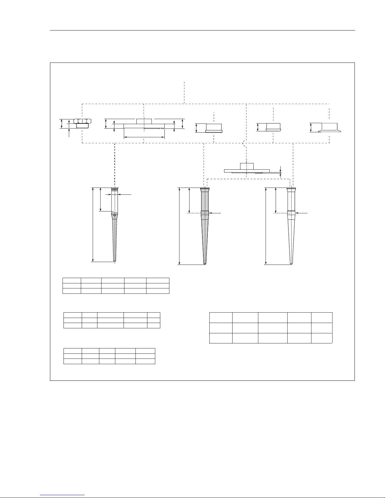
Micropilot M FMR 231 - process connection, type of antenna
L00-FMR231xx-06-00-00-en-005
a
a
L2
390 / 540
Ø 33
a
Ø 25
Ø D
L2
360 / 510
L2
390 / 540
Ø 33
43
b
b
23
a
a
41
77
44.5
80.5
41
77
41
77
b [mm]
DN 80DN 50
20 (24)20
200 (200)165
D [mm]
220
20
DN 100
285
22
DN 150
b [mm]
b [mm]
DN 80
3”
DN 50
2”
18
23.9 (28.4)
16
19.1
185
190.5 (209.5)
155
152.4
D [mm]
D [mm]
210
228.6 (254)
18
23.9 (31.8)
DN 100
4”
280
279.4
22
25.4
DN 150
6”
4
Threaded connection
1½” (R
or 1 ½ NPT
BSPT 1 ½”)
Flange DN 50…150
or equivalent
PPS, antistatic
PTFE, antistatic
Flange
cladded version
DN 50 dairy coupling
DIN 11851
2”/3” Tri-Clamp
ISO 2852
a [mm]
without gastight
feedthrough
a [mm]
with gastight
feedthrough
Flange
DN 50…150
DN 50 aseptic
coupling
DN 50 diary
coupling
2”/3”
Tri-Clamp
Process
connection
Inactive length, equivalent
to max. nozzle height
L2 = 100 mm / 250 mm
for PN 16 (for PN 40)
Flange
Flange to EN 1092-1 (agreeable to DIN 2527)
PTFE
(in conjunction with
)
DN50 aseptic/dairy coupling
respectively Tri-clamp
FDA-listed TFM 1600
for 10K
Flange
Flange to JIS B2220
for 150 lbs (for 300 lbs)
Flange
Flange to ANSI B16.5
DN 50 aseptic
DIN 11864-1 form A
with O-ring for tubes
according to DIN 11850
F12 / T12 / F23 housing
Page 14
Mounting Micropilot M FMR231 with FOUNDATION Fieldbus
14 Endress+Hauser
3.3.2 Engineering hints
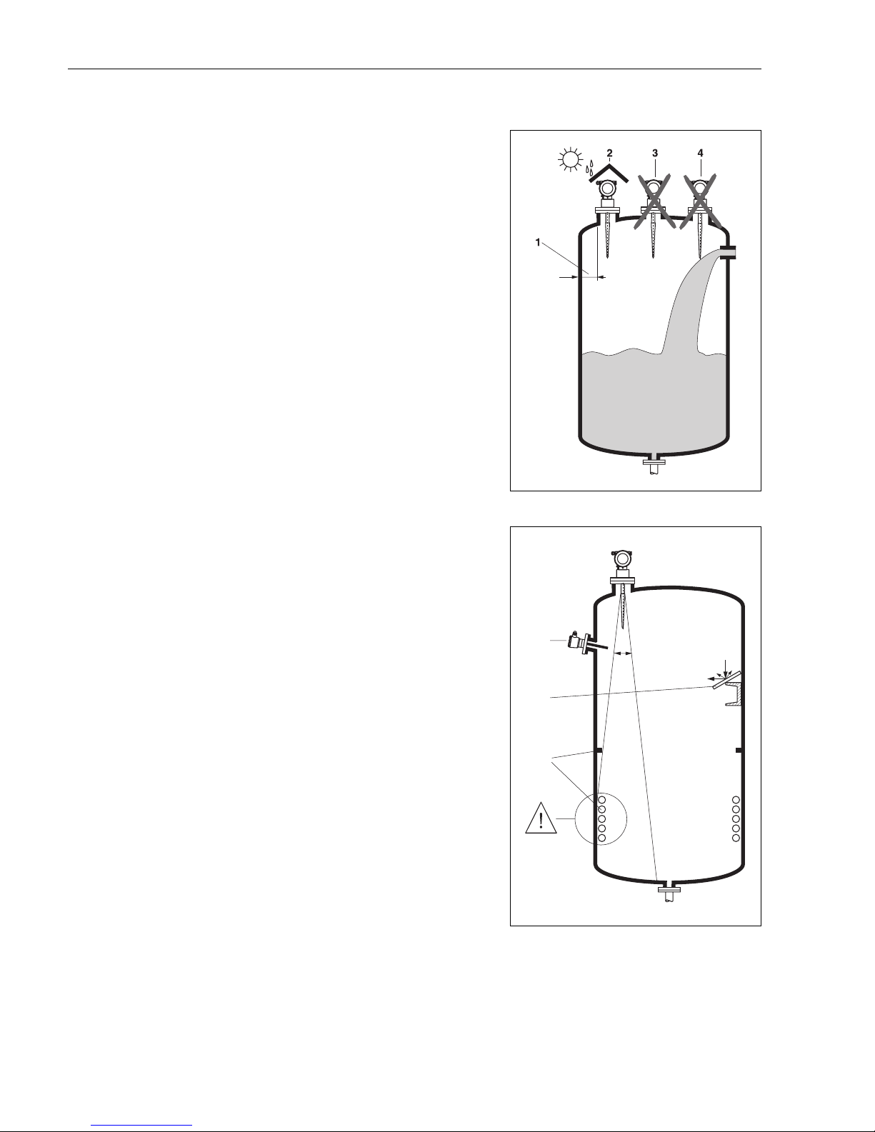
Orientation
• Recommended distance (1) wall – outer
edge of nozzle: ~1/6 of tank diameter.
Nevertheless the device should not be
installed closer than 30 cm (12“) to the
tankwall.
• Not in the centre (3), interference can cause
signal loss.
• Not above the fill stream (4).
• It is recommended to use a weather
protection cover (2) in order to protect the
transmitter from direct sun or rain. Assembly
and disassembly is simply done by means of a
tension clamp (→ Chap. 8 on Page 69).
L00-FMR2xxxx-17-00-00-xx-006
Tank installations
• Avoid any installations (1), like limit switches,
temperature sensors, etc., inside the signal
beam (refer to beam angle see "Beam angle"
on Page 16).
• Symmetrical installations (2), i.e. vacuum
rings, heating coils, baffles, etc., can also
interfere with the measurement.
Optimization options
• Antenna size: the bigger the antenna, the
smaller the beam angle, the less interference
echoes.
• Mapping: the measurement can be optimized
by means of electronic suppression of
interference echoes.
• Antenna alignment: refer to "optimum
mounting position"
• Stilling well: a stilling well can always be used
to avoid interference.
• Metallic screens (3) mounted at a slope spread
the radar signals and can, therefore, reduce
interference echoes.
Please contact Endress+Hauser for further
information.
L00-FMR2xxxx-17-00-00-xx-007
1
3
2
a
Page 15
Micropilot M FMR231 with FOUNDATION Fieldbus Mounting
Endress+Hauser 15
Measurement in a plastic tank
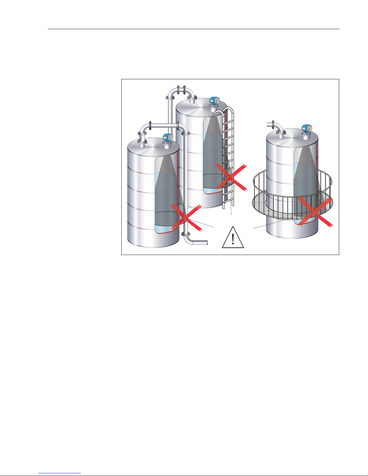
If the outer wall of the tank is made of a non-conductive material (e.g. GRP), microwaves can also
be reflected off interfering installations outside the signal beam (e.g. metallic pipes (1), ladders (2),
grates (3), …). Therefore, there should be no such interfering installations in the signal beam.
L00-FMR2xxxx-17-00-00-xx-013
Please contact Endress+Hauser for further information.
VH
00
VH
00
Endress+Hauser
Endress+Hauser
-
+
V
H
ENDRESS+HA
USER
MICROPILOT II
IP 65
O
r
d
e
r C
o
d
e
:
S
er
.-N
o
.:
M
es
sbe
re
ich
M
e
asu
r
in
g r
an
ge
U
16
...3
6
V D
C
4.
..2
0
m
A
m
a
x.
20
m
Made in Germany Maulburg
Made in Germany Maulburg
T>
7
0
°
C
:
A
t
>
8
5
°
C
VH
00
VH
00
Endress+Hauser
Endress+Hauser
-
+
V
H
ENDRESS+HA
USER
MICROPILOT II
IP 65
O
r
d
e
r
C
o
d
e:
S
er
.-N
o
.:
M
es
sbe
re
ich
M
easu
r
in
g r
an
ge
U 16
...3
6
V D
C
4.
..2
0
m
A
m
a
x.
20
m
Made in Germany Maulburg
Made in Germany Maulburg
T>
7
0
°
C
:
A
t
>
8
5
°
C
VH
00
VH
00
Endress+Hauser
Endress+Hauser
-
+
V
H
ENDRESS+HA
USER
MICROPILOT II
IP 65
O
rd
er
C
od
e
:
Se
r
.-N
o
.:
M
e
ssb
ereich
M
e
asur
ing
r
ang
e
U
1
6...36
V
D
C
4
...
2
0
m
A
m
ax.
20
m
Made in Germany Maulburg
Made in Germany Maulburg
T>
70
°
C
:
A
t
>
8
5
°
C
1
2
3
Page 16
Mounting Micropilot M FMR231 with FOUNDATION Fieldbus
16 Endress+Hauser
Beam angle
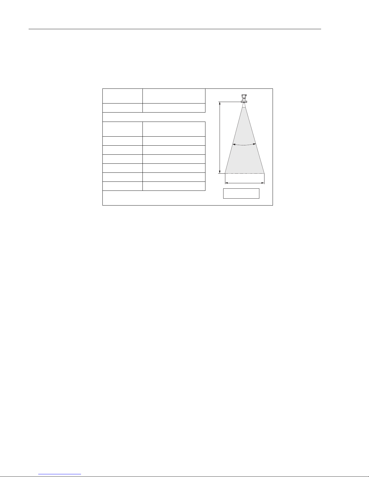
The beam angle is defined as the angle a where the energy density of the radar waves reaches half
the value of the maximum energy density (3dB-width). Microwaves are also emitted outside the
signal beam and can be reflected off interfering installations. Beam diameter W as function of
antenna type (beam angle α) and measuring distance D:
Antenna
FMR 231
Rod
L00-FMR2xxxx-14-00-06-de-027
Beam angle α 30°
Measuring dis-
tance (D)
Beam diameter (W)
Rod
3 m (10 ft) 1.61 m (5.36 ft)
6 m (20 ft) 3.22 m (10.72 ft)
9 m (30 ft) 4.82 m (16.08 ft)
12 m (40 ft) 6.43 m (21.44 ft)
15 m (49 ft) 8.04 m (26.26 ft)
20 m (65 ft) 10.72 m (34.83 ft)
a
D
W
a
D
_
=
2
2
..
tan
W
Page 17
Micropilot M FMR231 with FOUNDATION Fieldbus Mounting
Endress+Hauser 17
Measuring conditions
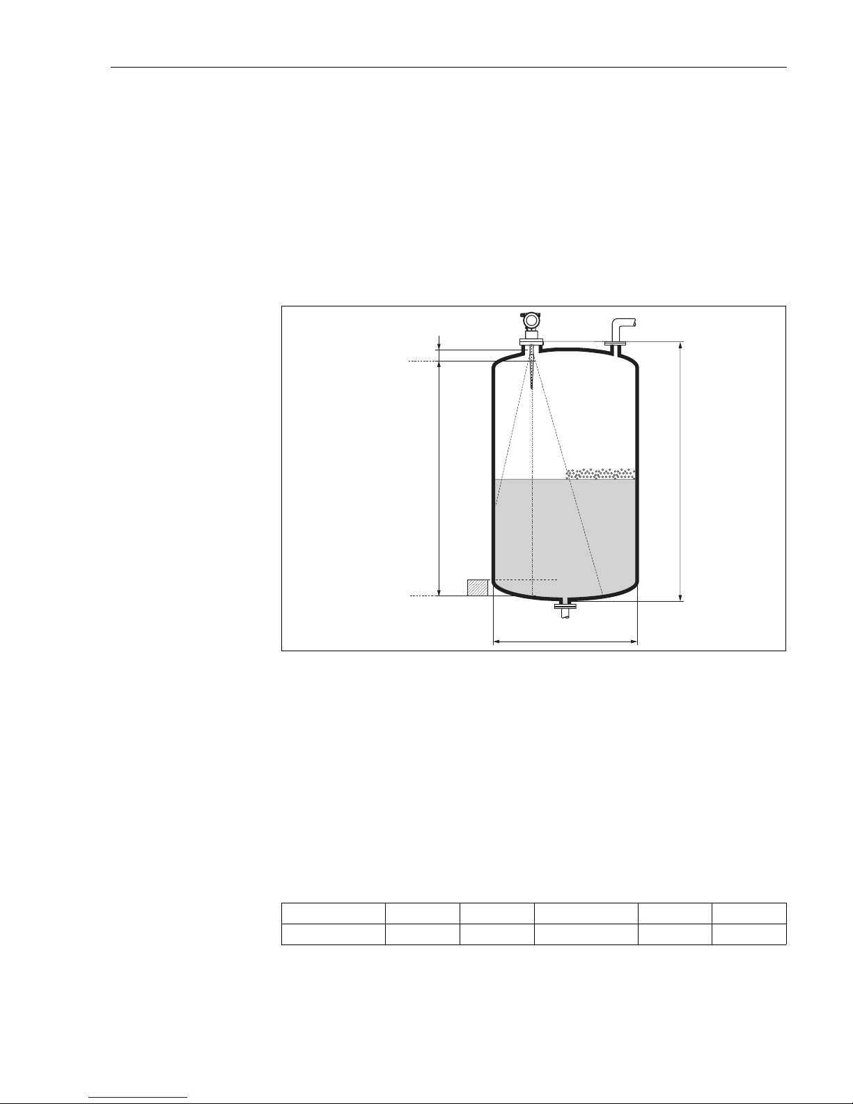
L00-FMR2xxxx-17-00-00-de-017
• The measuring range begins, where the beam hits the tank bottom. Particularly with dish bottoms
or conical outlets the level cannot be detected below this point.
• In case of media with a low dielectric constant (groups A and B), the tank bottom can be visible
through the medium at low levels (low height C). Reduced accuracy has to be expected in this
range. If this is not acceptable, we recommend positioning the zero point at a distance C (see Fig.)
above the tank bottom in these applications.
• In principle it is possible to measure up to the tip of the antenna with FMR230/231/240.
However, due to considerations regarding corrosion and build-up, the end of the measuring range
should not be chosen any closer than A (see Fig.) to the tip of the antenna.
For FMR244/245, the end of measuring range should not be chosen closer than A (see Fig.) to
the tip of the antenna, especially if there is development of condensate.
• The smallest possible measuring range B depends on the antenna version (see Fig.).
• The tank diameter should be greater than D (see Fig.), the tank height at least H (see Fig.).
Note!
• In case of boiling surfaces, bubbling or tendency for foaming, use FMR230 or FMR231.
Depending on its consistence, foam can either absorb microwaves or reflect them off the foam
surface. Measurement is possible under certain conditions.
• In case of heavy steam development or condensate the max. measuring range of FMR240 may
decrease depending on density, temperature and composition of the steam → use FMR230 or
FMR231.
• For the measurement of absorbing gases such as ammonia NH
3
or some fluorocarbons
1))
,
please use FMR230 in a stilling well.
1) Affected compounds are e.g. R134a, R227, Dymel 152a.
100%
0%
B
A
C
H
ØD
A [mm/inch] B [m/inch] C [mm/inch] D [m/inch] H [m/inch]
FMR231 50 / 2 > 0,5 / > 20 150...300 / 6...12 > 1 / > 40 > 1,5 / > 60
Page 18

Mounting Micropilot M FMR231 with FOUNDATION Fieldbus
18 Endress+Hauser
Measuring range
The usable measuring range depends on the size of the antenna, the reflectivity of the medium, the
mounting location and eventual interference reflections.
The maximum configurable range is:
• 20 m (65 ft) for Micropilot M FMR23x,
• 20 m (65 ft) for Micropilot M FMR24x,
– 40 m (131 ft) for Micropilot M FMR24x with additional option D (E), see "ordering
information",
– 70 M (229 ft) for Micropilot M FMR24x with additional option F (G), see "ordering
information",
• 70 m (229 ft) for Micropilot M FMR250 (further informations see TI390F/00/en).
The following tables describe the groups of media as well as the achievable measuring range as a
function of application and media group. If the dielectric constant of a medium is unknown, it is
recommended to assume media group B to ensure a reliable measurement.
Media group DC (εr) Examples
A 1,4...1,9 non-conducting liquids, e.g. liquefied gas
1))
1) Treat Ammonia NH3 as a medium of group A, i.e. use FMR230 in a stilling well.
B 1,9...4 non-conducting liquids, e.g. benzene, oil, toluene, …
C 4...10 e.g. concentrated acids, organic solvents, esters, aniline, alcohol, acetone, …
D > 10 conducting liquids, e.g. aqueous solutions, dilute acids and alkalis
Page 19
Micropilot M FMR231 with FOUNDATION Fieldbus Mounting
Endress+Hauser 19
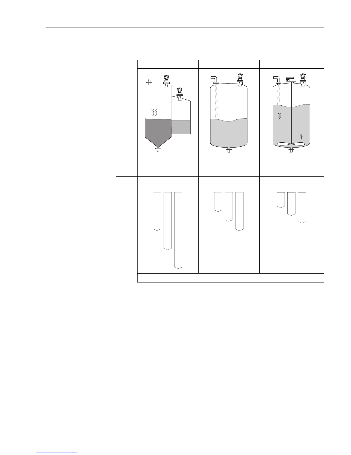
Measuring range depending on vessel type, conditions and product for
Micropilot M FMR231
Storage tank
1)
Buffer tank
1)
Process tank with agitator
1)
Calm product surface
(e.g. intermittent filling, filling
from bottom, immersion tubes).
Moving surfaces (e.g. continuous
filling, from above, mixing jets).
Turbulent surface.
Single stage agitator < 60 U/min.
FMR231: Rod antenna Rod antenna Rod antenna
Measuring range [m (ft)]
1) For media group A to use a stilling well (20 m / 65 ft).
BB
10
(33)
20
(65)
15
(49)
CCDD
BB
10
(33)
7.5
(24)
5
(16)
CCDD
BB
8
(27)
4
(13)
6
(20)
CCDD
Page 20
Mounting Micropilot M FMR231 with FOUNDATION Fieldbus
20 Endress+Hauser
3.4 Installation instructions
3.4.1 Mounting kit
In addition to the tool needed for flange mounting, you will require the following tool:
• 4 mm/0.1" Allen wrench for turning the housing.
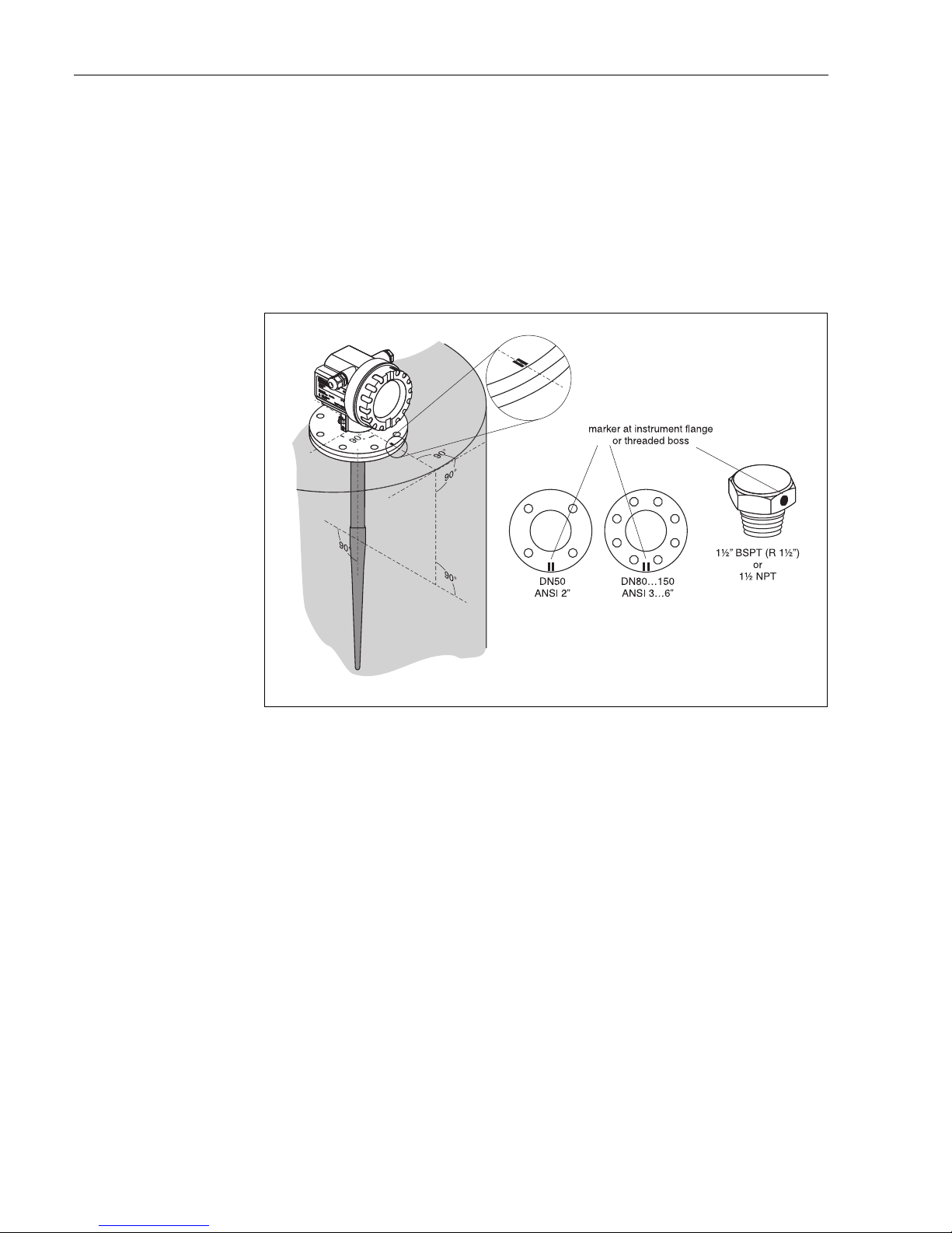
3.4.2 Installation in tank (free space)
Optimum mounting position
L00-FMR231xx-17-00-00-en-001
Standard installation
For installations in a stilling well, follow the engineering hints on Page 14 and note the following
points:
• Marker is aligned towards tank wall.
• The marker is always exactly in the middle between two bolt-holes in the flange.
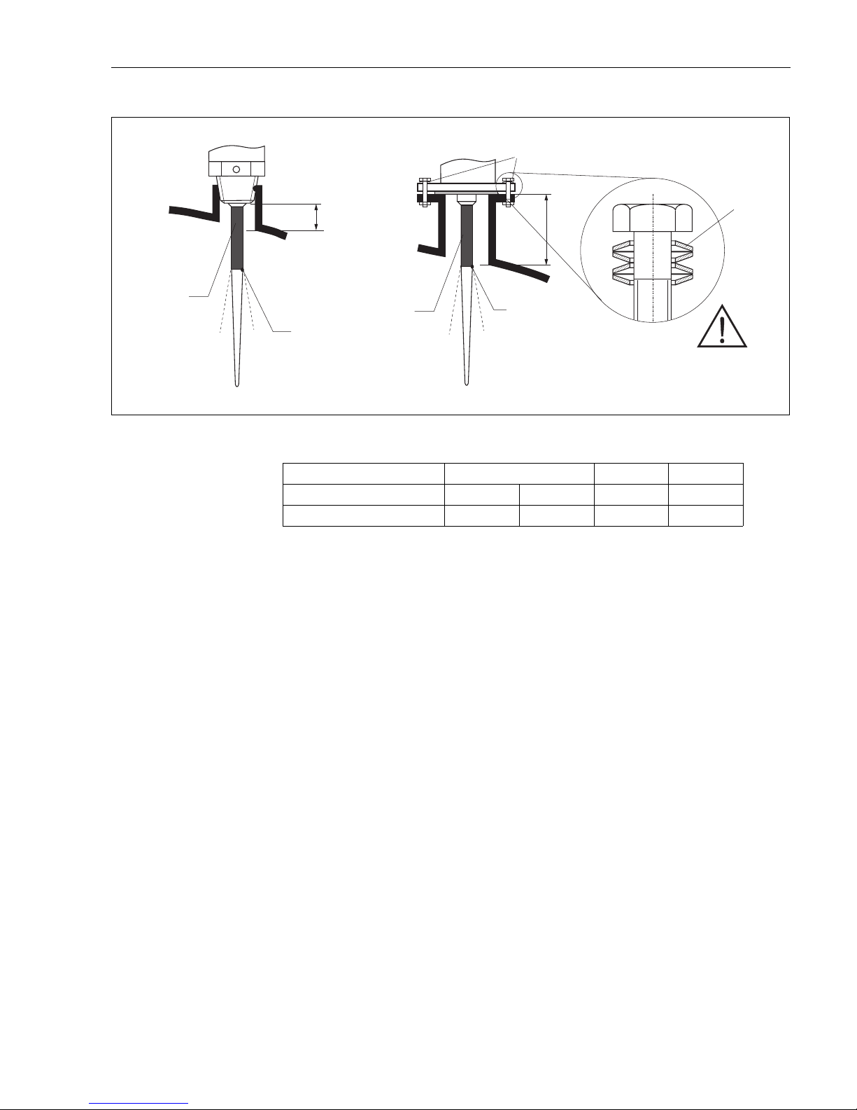
• Use spring washers (1) (see Fig.).
Note!
It is recommended to retighten the flange bolts periodically, depending on process temperature
and pressure. Recommended torque: 60...100 Nm.
• After mounting, the housing can be turned 350° in order to simplify access to the display and the
terminal compartment.
• The rod antenna must be aligned vertically.
Page 21
Micropilot M FMR231 with FOUNDATION Fieldbus Mounting
Endress+Hauser 21
L00-FMR231xx-17-00-00-en-002
H
H
1
beam launched
here
beam launched
here
inactive length
inactive length
spring washers
Material PPS PTFE
Antenna length [mm / inch] 360 / 14 510 / 20 390 / 15 540 / 21
H [mm/inch] < 100 / < 4 < 250 / < 10 < 100 / < 4 < 250 / < 10
Page 22
Mounting Micropilot M FMR231 with FOUNDATION Fieldbus
22 Endress+Hauser
3.4.3 Turn housing
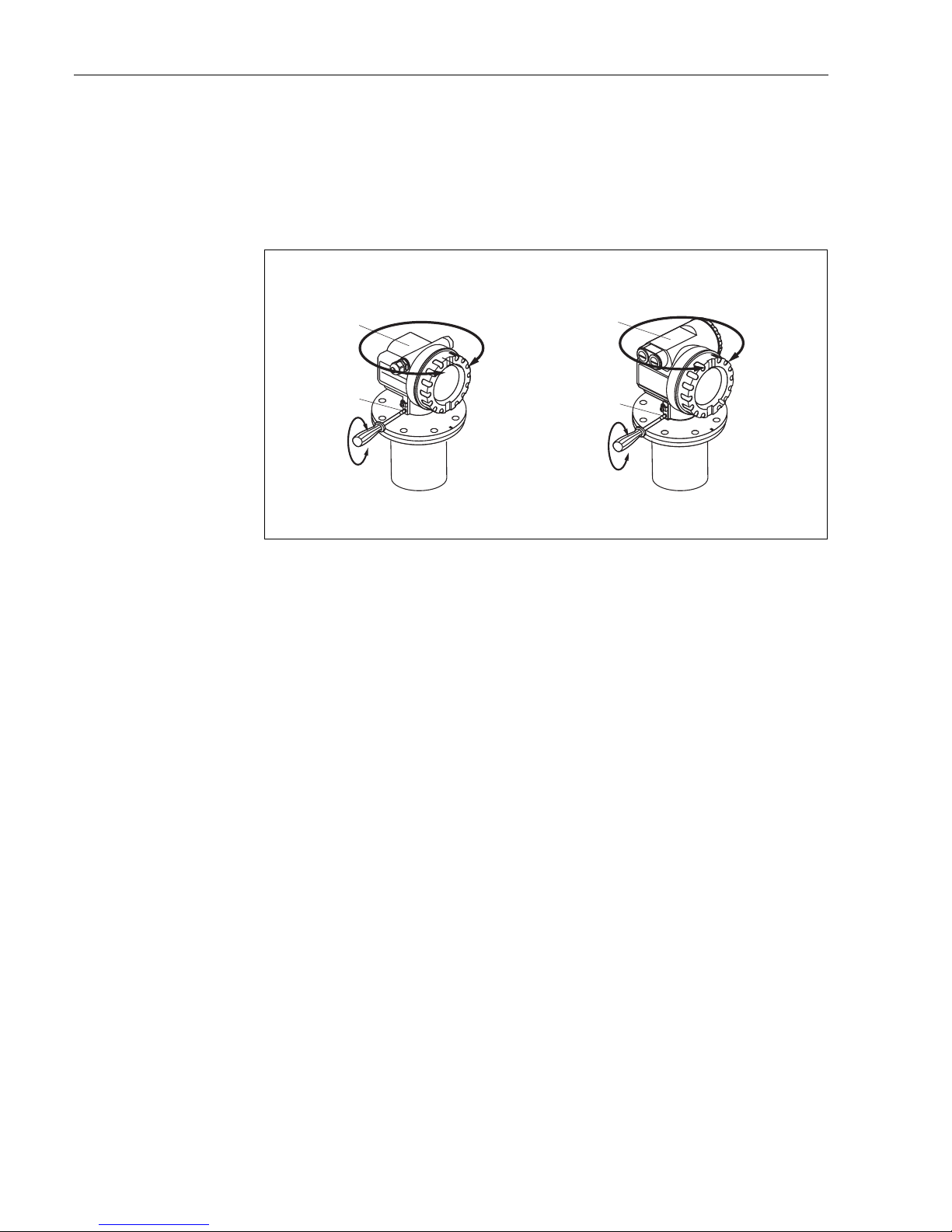
After mounting, the housing can be turned 350° in order to simplify access to the display and the
terminal compartment. Proceed as follows to turn the housing to the required position:
• Undo the fixing screws (1)
• Turn the housing (2) in the required direction
• Tighten up the fixing screws (1)
L00-FMR2xxxx-17-00-00-en-010
3.5 Post-installation check
After the measuring instrument has been installed, perform the following checks:
• Is the measuring instrument damaged (visual check)?
• Does the measuring instrument correspond to the measuring point specifications such as process
temperature/pressure, ambient temperature, measuring range, etc.?
• Is the flange marking correctly aligned? (→ Page 10)
• Have the flange screws been tightened up with the respective tightening torque?
• Are the measuring point number and labeling correct (visual check)?
• Is the measuring instrument adequately protected against rain and direct sunlight (→ Page 69)?
1
1
2
2
F12 / F23 housing T12 housing
allen key
4 mm/0.1”
Page 23
Micropilot M FMR231 with FOUNDATION Fieldbus Wiring
Endress+Hauser 23
4 Wiring
4.1 Quick wiring guide
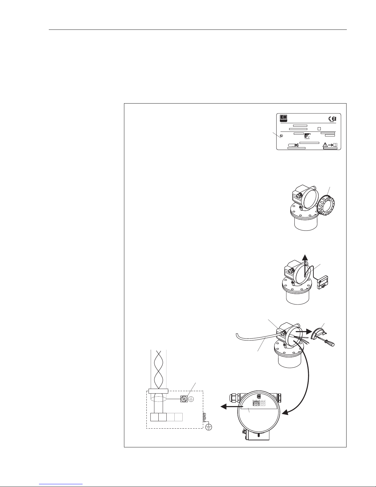
Wiring in F12/F23 housing
L00-FMR2xxxx-04-00-00-en-018
-
-
END
RESS+H
A
U
SER
ENDRESS+HAUSER
#
4
5
6
2
3
1234
1
"
Ser.-No.:
Order Code:
D01028-A
t >85°C
x=
if modification
see sep. label
Dat./Insp.:
PN max.
T
Antenne
max. °C
79689 Maulburg
Made in Germany
T >70°C :
A
MICROPILOT M
ENDRESS+HAUSER
PTB 00ATEX
II 1/2 G EEx ia IIC T6
IP65
Foundation Fieldbus
xxxxxxxx
xxxxxxxx
1
3
4
11
8
7
7
3
4
1
2
+–
Sealed terminal
compartment
When you use the measuring system in hazardous areas, make sure you comply with
national standards and the specifications in the safety instructions (XA’s).
Make sure you use the specific cable gland.
On devices supplied with a certificate, the explosion protection
is designed as follows:
Housing F12/F23 - EEx ia:
Power supply must be intrinsically safe.
The electronics and the current output are galvanically
separated from the antenna circuit.
●
●
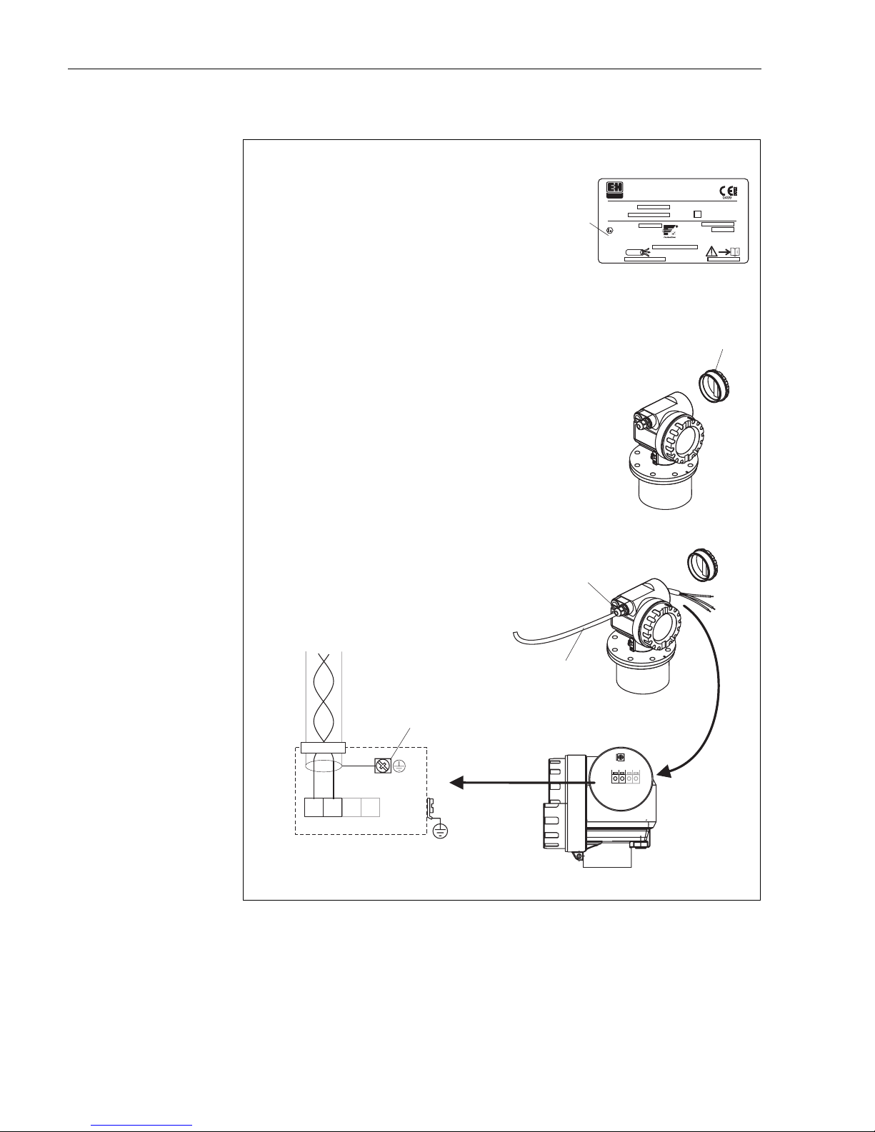
Connect up the Micropilot M as follows:
Unscrew housing cover (2).
Remove any display (3) if fitted.
Remove cover plate from terminal compartment (4).
Pull out terminal module slightly using pulling loop.
Insert cable (5) through gland (6).
Use screened, twisted wire pair.
Only earth screen conductor (7) on sensor side.
Make connection (see pin assignment).
Re-insert terminal module.
Tighten cable gland (6).
Tighten screws on cover plate (4).
Insert display if fitted.
Screw on housing cover (2).
●
●
●
●
●
●
●
●
●
●
●
Unplug display connector!
Before connection please note the following:
Foundation Fieldbus devices are marked on the nameplate
(1). The voltage is determined by the Foundation Fieldbus
standard and the desired safety concept. (see chapter 4.3).
Connect potential matching line to transmitter earth terminal
before connecting up the device.
Tighten the locking screw:
It forms the connection between the antenna and the housing
earth potential.
●
●
●
Caution!
plant
ground
Page 24
Wiring Micropilot M FMR231 with FOUNDATION Fieldbus
24 Endress+Hauser
Wiring in T12 housing
L00-FMR2xxxx-04-00-00-en-020
2
-
-
4
3
1234
1
"
Ser.-No.:
Order Code:
D01028-A
t >85°C
x=
if modification
see sep. label
Dat./Insp.:
PN max.
T
Antenne
max. °C
79689 Maulburg
Made in Germany
T >70°C :
A
MICROPILOT M
ENDRESS+HAUSER
PTB 00ATEX
II 1/2 G EEx ia IIC T6
IP65
Foundation Fieldbus
xxxxxxxx
xxxxxxxx
1
3
4
11
8
7
5
3
4
1
2
+–
When you use the measuring system in hazardous areas, make sure you comply with
national standards and the specifications in the safety instructions (XA’s).
Make sure you use the specific cable gland.
Connect up the Micropilot M as follows:
Before unscrew housing cover (2) at seperate connection room
turn off the power supply!
Insert cable (3) through gland (5).
Use screened, twisted wire pair.
Only ground screening of the line (5) on sensor side.
Make connection (see pin assignment).
Tighten cable gland (4).
Screw on housing cover (2).
Switch on power supply.
●
●
●
●
●
Before connection please note the following:
Foundation Fieldbus devices are marked on the nameplate
(1). The voltage is determined by the Foundation Fieldbus
standard and the desired safety concept. (see chapter 4.3).
Connect potential matching line to transmitter earth terminal
before connecting up the device.
Tighten the locking screw:
It forms the connection between the antenna and the housing
earth potential.
●
●
●
Caution!
plant
ground
Page 25
Micropilot M FMR231 with FOUNDATION Fieldbus Wiring
Endress+Hauser 25
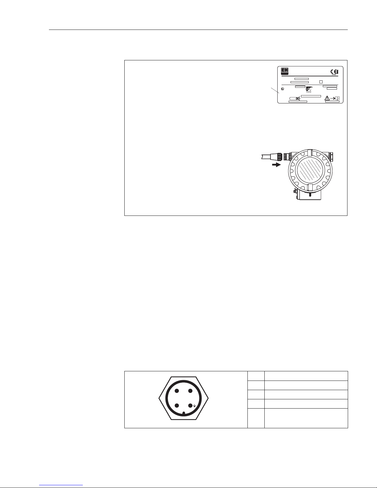
Wiring with Foundation Fieldbus connector
L00-FMR230xx-04-00-00-en-006
Cable specification Foundation Fieldbus
Twisted, shielded pairs must be used. The cable specifications can be taken from the FF specification
or IEC 61158-2. The following have been found suitable:
Non-Ex-area:
• Siemens 6XV1 830-5BH10,
• Belden 3076F,
• Kerpen CEL-PE/OSCR/PVC/FRLA FB-02YS(ST)YFL.
Ex-area:
• Siemens 6XV1 830-5AH10,
• Belden 3076F,
• Kerpen CEL-PE/OSCR/PVC/FRLA FB-02YS(ST)YFL.
Fieldbus plug connectors
For the versions with fieldbus plug connector (M12 or 7/8"), the signal line can be connected
without opening the housing.
Pin assignment of the 7/8" plug connector (FOUNDATION Fieldbus plug)
L00-FMxxxxxx-04-00-00-yy-017
Pin Meaning
1 Signal -
2 Signal +
3not connected
4ground
1
-
"
2
3
Ser.-No.:
Order Code:
D01028-A
t >85°C
x=
if modification
see sep. label
Dat./Insp.:
PN max.
T
Antenne
max. °C
79689 Maulburg
Made in German
y
T >70°C:
A
MICROPILOT M
ENDRESS+HAUSER
PTB 00ATEX
II 1/2 G EEx ia IIC T6
IP65
Foundation Fieldbus
xxxxxxxx
xxxxxxxx
1
3
4
11
8
7
Before connection please note the following:
Connect potential matching line to transmitter earth terminal
before connecting up the device.
Tighten the locking screw:
It forms the connection between the antenna and the housing
earth potential.
●
●
●
Foundation Fieldbus devices are marked on the nameplate
(1). The voltage is determined by the Foundation Fieldbus
standard and the desired safety concept. (see chapter 4.3).
When you use the measuring system in hazardous areas, make sure you comply with
national standards and the specifications in the safety instructions (XA’s).
Make sure you use the specific cable gland.
On devices supplied with a certificate, the explosion protection
is designed as follows:
Housing F12/F23 - EEx ia:
Power supply must be intrinsically safe.
The electronics and the current output are galvanically
separated from the antenna circuit.
●
●
Caution!
The Micropilot M is connected as follows:
Insert plug (2) into bushing (3).
Screw firmly.
Ground the device according to the desired safety concept.
●
●
●
2
1
3
4
+
–
nc
Page 26

Wiring Micropilot M FMR231 with FOUNDATION Fieldbus
26 Endress+Hauser
4.2 Connecting the measuring unit
Supply voltage
The following values are the voltages across the terminals directly at the instrument:
Current consumption
The current consumption approx 15 mA for the range of voltages given above.
Overvoltage protector
The level transmitter Micropilot M with T12-housing (housing version "D", see ordering
information) is equipped with an internal overvoltage protector (600 V surge arrester) according to
DIN EN 60079-14 or IEC 60060-1 (impulse current test 8/20 μs, Î = 10 kA, 10 pulses). Connect
the metallic housing of the Micropilot M to the tank wall or screen directly with an electrically
conductive lead to ensure reliable potential matching.
4.3 Recommended connection
For maximum EMC protection please observe the following points:
• The external ground terminal on the transmitter must be connected to ground.
• The continuity of the cable screening between tapping points must be ensured.
• If potential equalisation is present between the individual grounding points, ground the screening
at each cable end or connect it to the device housing (as short as possible).
• If there are large differences in potential between grounding points, the grounding should run via
a capacitor that is suitable for high frequency use (e.g. ceramic 10 nF/250 V&).
"
Caution!
Applications, which are subject to the explosion prevention, permit only under special conditions
the repeated grounding of the protective screen , see to EN 60 079-14..
4.4 Degree of protection
• with closed housing: IP65, NEMA4X
• with open housing: IP20, NEMA1 (also ingress protection of the display)
• antenna: IP68 (NEMA6P)
4.5 Post-connection check
After wiring the measuring instrument, perform the following checks:
• Is the terminal allocation correct (→ Page 23 and Page 25)?
• Is the cable gland tight?
• If available: Is the FOUNDATION Fieldbus connector screwed tight?
• Is the housing cover screwed tight?
• If auxiliary power is available:
Is the instrument ready for operation and does the liquid crystal display show any value?
Type Terminal voltage
minimum maximum
standard 9 V 32 V
EEx ia (FISCO model) 9 V 17, 5 V
EEx ia (Entity concept) 9 V 24 V
Page 27
Micropilot M FMR231 with FOUNDATION Fieldbus Operation
Endress+Hauser 27
5Operation
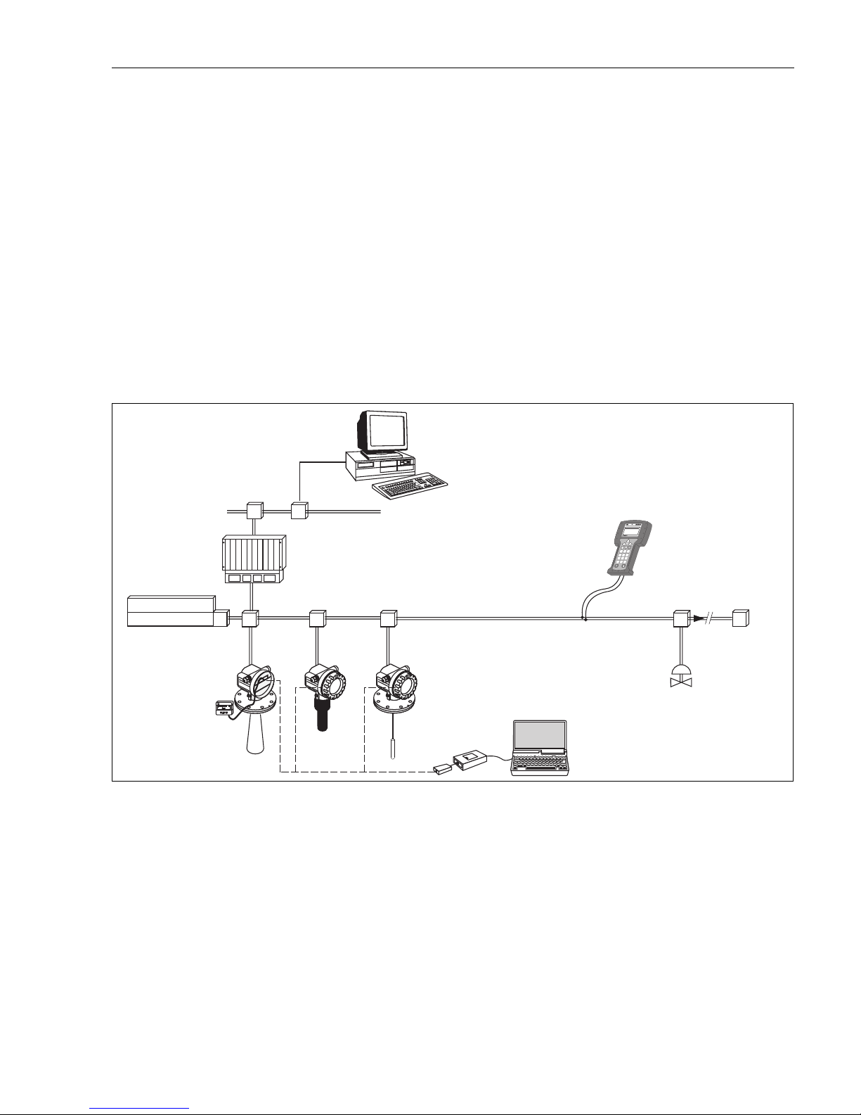
This chapter gives an overview of the different operating options for the device. The different
methods of parameter access are described and the preconditions for each method are stated.
The meaning of the parameters is not described in this chapter. Instead, refer to:
• Chapter 6: "Commissioning"
• Operating Instructions BA221F: "Micropilot M - Description of Instrument Functions"
This chapter contains the following sections:
• 5.1 Operating options
• 5.2 Operation with the display and operating module VU331
• 5.3 Operation with an Endress+Hauser operating software
• 5.4 Operation with a FOUNDATION Fieldbus configuration software
• 5.5 Operatin with the handhelt terminal DXR375/FC375
5.1 Operating options
L00-FMxxxxxx-14-00-06-de-011
T T
ENDRESS + HAUSER
E
+–
%
1
# % &
Copy
G H I
P Q R S
, ( )‘
A B C
Paste
Page
On
Page
Up
DeleteBksp
Insert
J K L
T UV
_ < >
D E F
Hot Key
+ Hot Key
M N O
W XY Z
+ * /
4
7
.
2
5
8
0
375
FIELD COMMUNICATOR
3
6
9
-
9
6
DELTABAR:* * * * * * * *
ONLINE
1 QUICK SETUP
2 OPERATING MENU
4 SV 0 °C
3 PV 352 mbar
HELP SAVE
dsdmdm
df das.
asdas fa
asas la.
1
# % &
Copy
G H I
P Q R S
, ( )‘
A B C
Paste
Page
On
Page
Up
DeleteBksp
Insert
J K L
T UV
_ < >
D E F
Hot Key
+ Hot Key
M N O
W XY Z
+ * /
4
7
.
2
5
8
0
375
FIELD COMMUNICATOR
3
6
9
-
9
6
DELTABAR:* * * * * * * *
ONLINE
1 QUICK SETUP
2 OPERATING MENU
4 SV 0 °C
3 PV 352 mbar
HELP SAVE
dsdmdm
df das.
asdas fa
asas la.
Ethernet
SPS
PLC
API
FF link
FOUNDATION Fieldbus
Micropilot M
Prosonic M
Levelflex M
DXR375/FC375
FXA193/291
ToF Tool - FieldTool Package
FieldCare
ControlCare
DeltaV
...
power supply
power conditioner
Anzeige- und
Bedienmodul
VU331
Weitere
Funktionen
(Ventile etc.)
Page 28
Operation Micropilot M FMR231 with FOUNDATION Fieldbus
28 Endress+Hauser
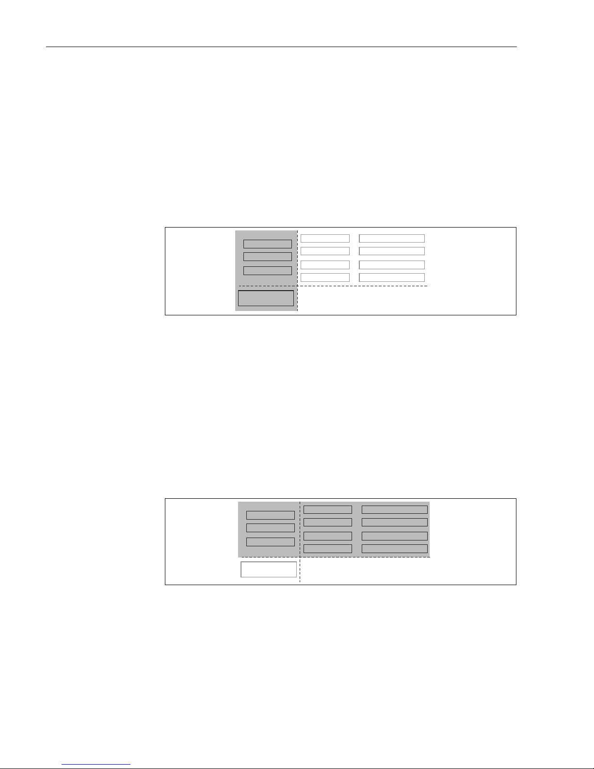
5.1.1 On-site operation
Options for on-site operation
• Display and operating module VU331
• Endress+Hauser operating software ("ToF Tool - FieldTool Package" or "FieldCare")
Parameter access by on-site operation
The following parameters can be accessed by on-site operation:
• Parameters of the device specific blocks (Sensor Block, Diagnostic Block, Display Block)
• Endress+Hauser service parameters
• in the Resource Block: "Device Tag", "Device ID", "Device Revision", "DD Revision" (read only)
L00-FMU4XXXX-02-00-00-YY-005
The highlighted parameters can be edited by on-site operation.
5.1.2 Remote operation
Options for remote operation
• FOUNDATION Fieldbus configuration tool (e.g. DeltaV or ControlCare)
• Handheld terminal DXR375/FC375
Parameter access by remote operation
The following parameters can be accessed by remote operation:
• Parameters of the device specific blocks (Sensor Block, Diagnostic Block, Display Block)
• Parameters of the FOUNDATION Fieldbus function blocks
L00-FMU4XXXX-02-00-00-YY-006
The highlighted parameters can be edited by remote operation.
Endress+Hauser
Service-Parameter
Sensorblock
Diagnoseblock
Display-Block
Resource Block
AI-Block 1
AI-Block 2
PID Block
Arithmetik-Block
Input-Selector-Block
Signal-Charact.-Block
Integrator-Block
Endress+Hauser
Service-Parameter
Sensorblock
Diagnoseblock
Display-Block
Resource Block
AI-Block 1
AI-Block 2
PID Block
Arithmetik-Block
Input-Selector-Block
Signal-Charact.-Block
Integrator-Block
Page 29
Micropilot M FMR231 with FOUNDATION Fieldbus Operation
Endress+Hauser 29
5.2 Operation with the display and operating module
VU331
L00-FMxxxxxx-07-00-00-en-001
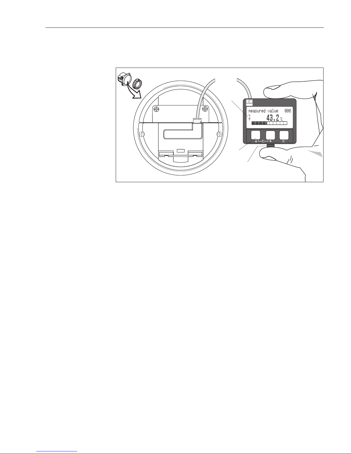
Fig. 2: Layout of the display and operating elements
The VU331 LCD display can be removed to ease operation by simply pressing the snap-fit (see
graphic above). It is connected to the device by means of a 500 mm cable.
!
Note!
To access the display the cover of the electronic compartment may be removed even in hazardous
area (IS and XP).
ENDRESS + HAUSER
E
+
–
E
NDR
ES
S+HA
USER
MICRO
PILO
T
II
ENDRESS+HAUSER
MICROPILOTII
IP65
IP65
O
rd
e
r
C
o
de
:
Se
r
.-N
o.:
Order
Code:
Ser.-No.:
M
es
sb
e
re
ich
M
easuring
ra
nge
Messbereich
Measuring
range
U
16
..
.3
6
V
D
C
4...20
m
A
U16...36
V
DC
4...20
mA
m
ax
.
2
0
m
max.
20
m
MadeinGermany Maulburg
MadeinGermany Maulburg
T>
7
0
°C
:
A
t>
85°
C
T>70°C
:
A
t
>85°C
LCD
(liquid crystal display)
Symbols
3 keys
snap-fit
Page 30
Operation Micropilot M FMR231 with FOUNDATION Fieldbus
30 Endress+Hauser
5.2.1 Display
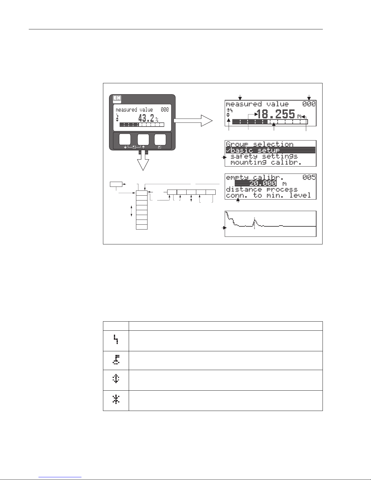
Liquid crystal display (LCD):
Four lines with 20 characters each. Display contrast adjustable through key combination.
L00-FMRxxxxx-07-00-00-en-002
Fig. 3: Display
In the measured value display, the bargraph corresponds to the output.
The bargraph is segmented in 10 bars. Each completely filled bar represents a change of 10% of the
adjusted span.
5.2.2 Display symbols
The following table describes the symbols that appear on the liquid crystal display:
X
X
X
X
S
S
O
O
FF
F
F
HOME
FG00
F000 F001 F002 F003 F004 ...
FG01
FG02
FG03
FG04
FG05
FG06
FG07
...
+21dB 09C
10.002.305m
0.00
ENDRESS + HAUSER
E
+
–
Headline Position indicator
Main value
Unit
Symbol
Selection list
Function groups -> Functions
Help text
Envelope
curve
Bargraph
Sybmol Meaning
ALARM_SYMBOL
This alarm symbol appears when the instrument is in an alarm state. If the symbol flashes, this indicates a
warning.
LOCK_SYMBOL
This lock symbol appears when the instrument is locked,i.e. if no input is possible.
COM_SYMBOL
This communication symbol appears when a data transmission via e.g. HART, PROFIBUS PA or
FOUNDATION Fieldbus is in progress.
SIMULATION_SWITCH_ENABLE
This communication symbol appears when simulation in FOUNDATION Fieldbus is enabled via the DIP
switch.
Page 31

Micropilot M FMR231 with FOUNDATION Fieldbus Operation
Endress+Hauser 31
5.2.3 Function of the keys
Key(s) Meaning
O
or
V
Navigate upwards in the selection list
Edit numeric value within a function
S
or
W
Navigate downwards in the selection list
Edit numeric value within a function
X
or
Z
Navigate to the left within a function group
F
Navigate to the right within a function group, confirmation.
O
and
F
or
S
and
F
Contrast settings of the LCD
O
and S and
F
Hardware lock / unlock
After a hardware lock, an operation of the instrument via display or
communication is not possible!
The hardware can only be unlocked via the display. An unlock parameter must
be entered to do so.
Page 32
Operation Micropilot M FMR231 with FOUNDATION Fieldbus
32 Endress+Hauser
5.2.4 The operating menu
General structure of the operating menu
The operating menu is made up of two levels:
• Function groups (00, 01, 03, …, 0C, 0D): The individual operating options of the instrument
are split up roughly into different function groups. The function groups that are available include,
e.g.: "basic setup", "safety settings", "output", "display", etc.
• Functions (001, 002, 003, …, 0D8, 0D9): Each function group consists of one or more
functions. The functions perform the actual operation or parameterisation of the instrument.
Numerical values can be entered here and parameters can be selected and saved. The available
functions of the “basic setup” (00) function group include, e.g.: "tank shape" (002),
"medium property" (003), "process cond." (004), "empty calibr." (005), etc.
If, for example, the application of the instrument is to be changed, carry out the following
procedure:
1. Select the “basic setup” (00) function group.
2. Select the "tank shape" (002) function (where the existing tank shape is selected).
Identifying the functions
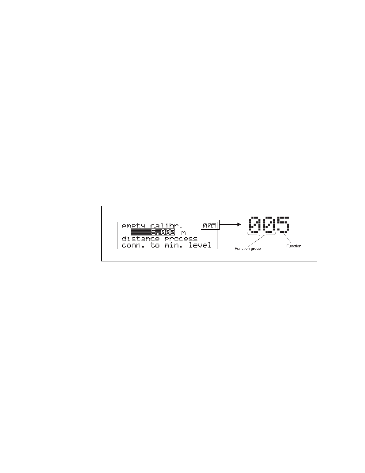
For simple orientation within the function menus (see Page 96 ff.), for each function a position is
shown on the display.
L00-FMRxxxxx-07-00-00-en-005
The first two digits identify the function group:
The third digit numbers the individual functions within the function group:
Hereafter the position is always given in brackets (e.g. "tank shape" (002)) after the described
function.
• basic setup 00
• safety settings 01
• linearisation 04
. . .
• basic setup 00 → • tank shape 002
• medium property 003
• process cond. 004
. . .
Page 33
Micropilot M FMR231 with FOUNDATION Fieldbus Operation
Endress+Hauser 33
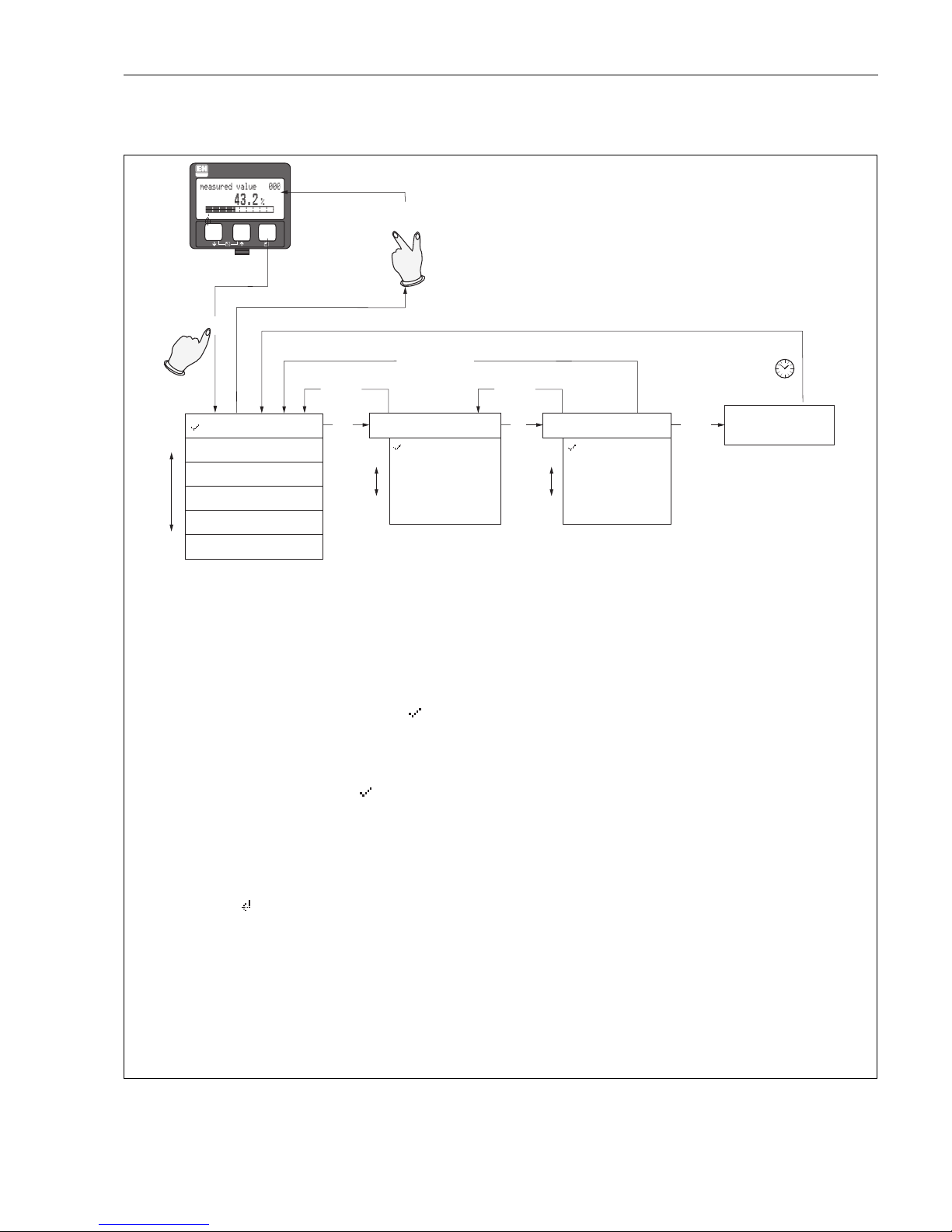
Navigation within the menu
L00-FMR2xxxx-19-00-00-en-001
ENDRESS + HAUSER
E
+
–
X
X
X
X
S
SS
O
OO
FF
>3 s
F
...
2x
...
...
unknown
DC: < 1.9
DC: 1.9 ... 4
DC: 4 ... 10
DC: > 10
Selection and configuration in Operation menu:
Group Selection
Function Group
unction
Note!
Selection menus:
function
Typing in numerals and text:
numeral / text
function
function
Group selection
Measured value display
1.) Change from Measured Value Display to by pressing
2.) Press or to select the required (e.g.. "basic setup (00)") and confirm by pressing
(e.g. "tank shape (002)") is selected.
The active selection is marked by a in front of the menu text.
3.) Activate Edit mode with or .
a) Select the required in selected (e.g. "tank shape (002)") with or .
b) confirms selection appears in front of the selected parameter
c) confirms the edited value system quits Edit mode
d) + (= ) interrupts selection system quits Edit mode
a) Press or to edit the first character of the (e.g. "empty calibr. (005)")
b) positions the cursor at the next character (a) until you have completed your input
c) if a symbol appears at the cursor, press to accept the value entered
system quits Edit mode
d) + (= ) interrupts the input,
4) Press to select the next (e.g. "medium property (003)")
5) Press + (= ) once return to previous (e.g. "tank shape (002)")
Press + (= ) twice return to
6) Press + (= ) to return to
F
SO
O
SO
F
S
X
S
F
S
F
F
OS X
OS
F
OX
F
OS X
OS
OX
Ü
Ü
Ü
Ü
Ü
Ü
Ü
First f
continue with
system quits Edit mode
Ü
Parameter
Return to
Group Selection
basic setup
safety settings
linearisation
tank shape
dome ceiling
horizontal cyl
bypass
stilling well
flat ceiling
sphere
medium property
extended calibr.
Page 34

Operation Micropilot M FMR231 with FOUNDATION Fieldbus
34 Endress+Hauser
5.3 Operation with an Endress+Hauser operating program
5.3.1 ToF Tool – Fieldtool Package
The ToF Tool is a graphic and menu-guided operating program for measuring devices from
Endress+Hauser. It is used for the commissioning, data storage, signal analysis and documentation
of the devices. The following operating systems are supported: WinNT4.0, Win2000 and
Windows XP. You can set the parameters of the device specific blocks via the ToF Tool.
The ToF Tool supports the following functions:
• Configuration of transmitters in online operation
• Singal analysis via envelope curve
• Tank linearisation
• Loading and saving device data (upload/download)
• Documentation of the measuring point
Connection options:
• via the FXA193/FXA291 service interface
!
Note!
You can use the ToF Tool to configure the metrological parameters for devices with "FOUNDATION
Fieldbus signal". You need an FF configuration program to be able to configure all the FF-specific
parameters and to integrate the device into a FF network (see sections 5.1.1 and 5.1.2).
5.3.2 FieldCare
FieldCare is an Endress+Hauser asset management tool based on FDT technology. With FieldCare,
you can configure all Endress+Hauser devices as well as devices from other manufacturers that
support the FDT standard. The following operating systems are supported: WinNT4.0, Win2000
and Windows XP.
Functions
FieldCare supports the following functions:
• Configuration of transmitters in online operation
• Singal analysis via envelope curve
• Tank linearisation
• Loading and saving device data (upload/download)
• Documentation of the measuring point
Page 35
Micropilot M FMR231 with FOUNDATION Fieldbus Operation
Endress+Hauser 35
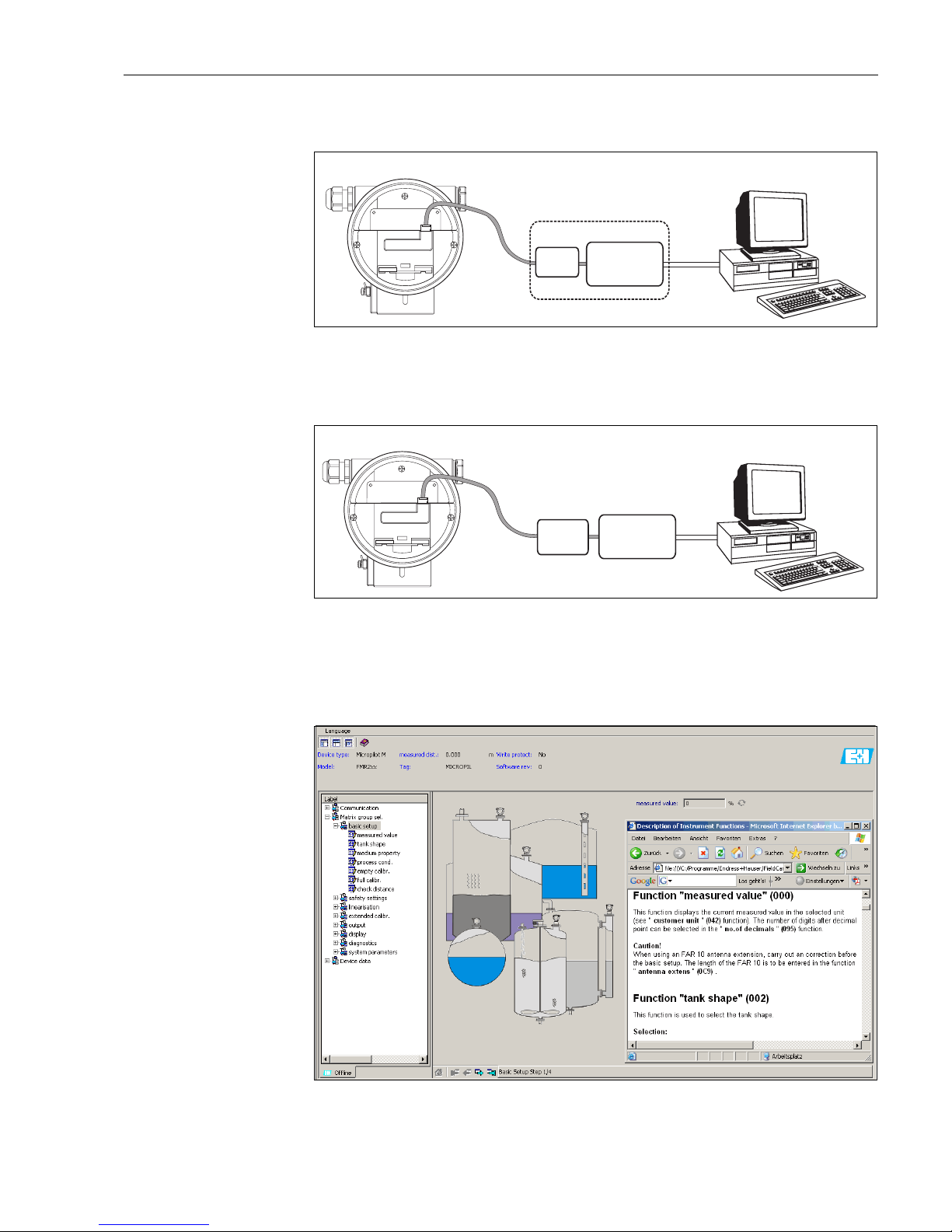
Connection with FXA193 (RS232C)
L00-FMxxxxxx-04-00-00-yy-023
For details refer to Technical Information TI063D (FXA193).
Connection with FXA291 (USB)
L00-FMxxxxxx-04-00-00-yy-024
For details refer to:
Technical Information TI405C (Commubox FXA291)
Operating Instructions KA271 (ToF Adapter FXA291)
Menu-guided commissioning
MicropilotM-en-305
RS232C
ToF Tool-Fieldtool Package
FieldCare
FXA193
USB
Commubox
FXA291
ToF Tool-Fieldtool Package
FieldCare
ToF
Adapter
FXA291
Page 36
Operation Micropilot M FMR231 with FOUNDATION Fieldbus
36 Endress+Hauser
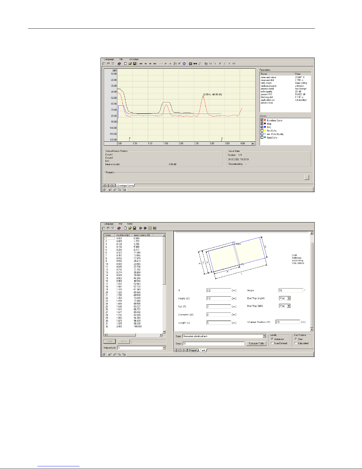
Signal analysis via envelope curve
MicropilotM-en-306
Tank linearisation
MicropilotM-en-307
Page 37

Micropilot M FMR231 with FOUNDATION Fieldbus Operation
Endress+Hauser 37
5.4 Operation with a FOUNDATION Fieldbus
configuration program
5.4.1 FOUNDATION Fieldbus configuration programs
The user can obtain special configuration and operating programs offered by different manufacturers
for use in configuration. These can be used for configuring both the FOUNDATION Fieldbus
functions and all the device-specific parameters. The predefined function blocks allow uniform
access to all the network and fieldbus device data.
5.4.2 Device Description files
File names
You will need the following files for commissioning and network configuration:
• Device Description files: *.sym, *.ffo
These files describe the structure of the blocks and their parameters. They offer guided setups with
the help of menus and methods.
• Capability file: *.cff
This file enables offline configuration and describes the device capability in terms of
communication stack and function blocks.
The file names consist of the following parts:
• Device Revision (0C3)
1)
• DD Revision (0C4)1 (use the most current version)
• CFF Revision (use the most current version)
Example:
• Device Revision (0C3) = 03
• DD Revision (0C4) = 01
• CFF Revision = 02
• -> files to be used: "0301.sym", "0301.ffo", "030102.cff"
Directory structure
The files are normally stored in the following directory structure:
• /452B48/100F/*.sym
*.ffo
*.cff
The directory names have the following meaning:
• 452B48: manufacturer ID of Endress+Hauser
• 100F: device ID of Micropilot M
1) "Device Revision" (0C3) and "DD Revision" (0C4) can be obtained through the display and operating module VU331. For details refer to section 5.2: "Operation
with the display and operating module VU331"
Page 38

Operation Micropilot M FMR231 with FOUNDATION Fieldbus
38 Endress+Hauser
Source of supply
5.4.3 Representation of parameters
A FOUNDATION Fieldbus configuration tool offers two types of parameter representation:
• Representation by parameter name
Examples: "PAROPERATIONCODE", "PARRESET"
• Representation by parameter label
(identical to the labels on the display module VU331 and in an Endress+Hauser operation tool)
Examples: "unlock parameter", "reset"
Host System Source of supply for the Device Description and Network Configuration files
ABB (Field Controller 800)
Allen Bradley (Control Logix)
Endress+Hauser (ControlCare)
Honeywell (Experion PKS)
Invensys
SMAR (System 302)
• www.endress.de (-> Download -> Media type = "Software", "Device Drivers")
• CD-ROM (Endress+Hauser order code: 56003896)
• www.fieldbus.org
Emerson (Delta V) • www.easydeltav.com
Yokogawa (CENTUM CS 3000) • www.yokogawa.com
Page 39

Micropilot M FMR231 with FOUNDATION Fieldbus Operation
Endress+Hauser 39
5.5 Operation with the handheld terminal DXR375/FC375
5.5.1 Connection
The handheld terminal is directly connected to the FOUNDATION Fieldbus communication line.
An additonal communication resistor is not required.
5.5.2 Device Descriptions
Make sure you have loaded the valid Device Description files (DDs). DDs can be downloaded from
the internet at "www.fieldcommunicator.com". The DDs can also be updated by the update
functionality of the DXR375/FC375.
5.5.3 User interface
The device parameters are arranged in blocks. The handheld terminal DXR375/FC375 uses this
block structure to access the parameters. You can navigate within the structure by the arrow keys
and the "Enter" key. Alternatively, you can use the touch-screen functionality of the handheld
terminal for navigation. (Double-click on a name opens the respective block or parameter).
Page 40
Operation Micropilot M FMR231 with FOUNDATION Fieldbus
40 Endress+Hauser
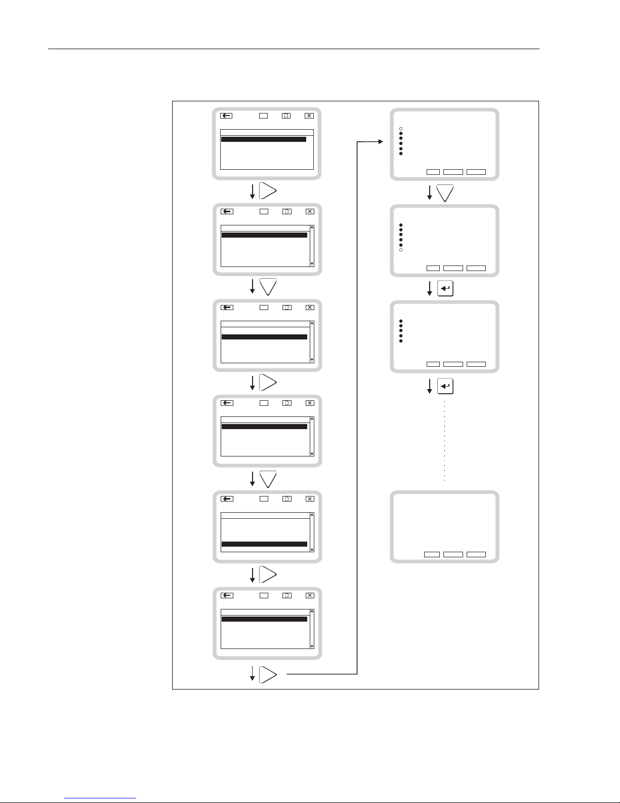
5.5.4 Example
L00-FMR2xxxx-07-00-00-yy-010
Micropilot M E+H_MICROPILOT_M_XXXXXX
Endress+Hauser Device Revision 4
dsdmdm
df das.
asdasfa
asasla.
LAS
Block Tag Actual Mode
SENSOR_B... Custom OOS
DIAGNOSTI... Custom
OOS
DISPLAY_B... Custom OOS
ANALOG_IN... AI OOS
9
RESOURCE... Auto
Fieldbus Live Device List
Number of Devices found = 1
dsdmdm
df das.
asdasfa
asasla.
LAS
Tag Address
375 Field Communicator
9
E+H_MICROPILOT_M_XXXXXXX 247
252
Block Type
RES_BL...
Delete
ANALOG_IN... AI OOS
Page
Dn
Micropilot M E+H_MICROPILOT_M_XXXXXX
Endress+Hauser Device Revision 4
dsdmdm
df das.
asdasfa
asasla.
LAS
Block Tag Actual Mode
DIAGNOSTI... Custom
OOS
DISPLAY_B... Custom OOS
ANALOG_IN... AI OOS
9
RESOURCE... Auto
Block Type
RES_BL...
ANALOG_IN... AI OOS
SENSOR_B... Custom OOS
Delete
Micropilot M E+H_MICROPILOT_M_XXXXXX
SENSOR_BLOCK_XXXXXXXXXXXXXXXX
dsdmdm
df das.
asdasfa
asasla.
LAS
Label Units
Other
All
Calibration Met...
9
Value
Status
Process
Micropilot M E+H_MICROPILOT_M_XXXXXX
SENSOR_BLOCK_XXXXXXXXXXXXXXXX
dsdmdm
df das.
asdasfa
asasla.
LAS
Label Units
Other
All
9
Value
Status
Process
Page
Dn
Calibration Met...
Micropilot M E+H_MICROPILOT_M_XXXXXX
SENSOR_BLOCK_XXXXXXXXXXXXXXXX
dsdmdm
df das.
asdasfa
asasla.
LAS
Label Units
linearisation
extended calibr.
9
Value
safety settings
output
Delete
basic setup
Delete
basic setup
tank shape: dome ceiling
dome ceiling
horizontal cyl.
bypass
stilling well
flat ceiling
sphere
NEXT
CANCEL HELP
basic setup
tank shape: dome ceiling
dome ceiling
horizontal cyl
bypass
stilling well
flat ceiling
sphere
NEXT
CANCEL HELP
Page
Dn
basic setup
medium cond.: unknown
unknown
DC: < 1.9
DC: 1.9 ... 4
DC: 4 ... 10
DC: > 10
NEXT
CANCEL HELP
basic setup
method completed successfully
FINISH
CANCEL HELP
Page 41
Micropilot M FMR231 with FOUNDATION Fieldbus Commissioning
Endress+Hauser 41
6 Commissioning
This chapter consists of the following sections:
• 6.1 Function check
• 6.2 Unlocking the device
• 6.3 Parameter reset
• 6.4 Commissioning with display and operating module VU331
• 6.5 Commissioning with Endress+Hauser operating software
• 6.6 Commissioning with FOUNDATION Fieldbus configuration tool
• 6.7 Commissioning with handheld terminal DXR375/FC375
6.1 Function check
Make sure that all final checks have been completed before you start up your measuring point:
• Checklist “Post installation check” (see chapter 3.5).
• Checklist “Post connection check” (see chapter 4.5).
6.2 Unlocking the device
Before commissioning, make sure that the device is not locked against parameter changes. On
delivery, the device is unlocked. In other cases, however, it may have been locked in one of the
following ways:
6.2.1 DIP switch (under the housing cover)
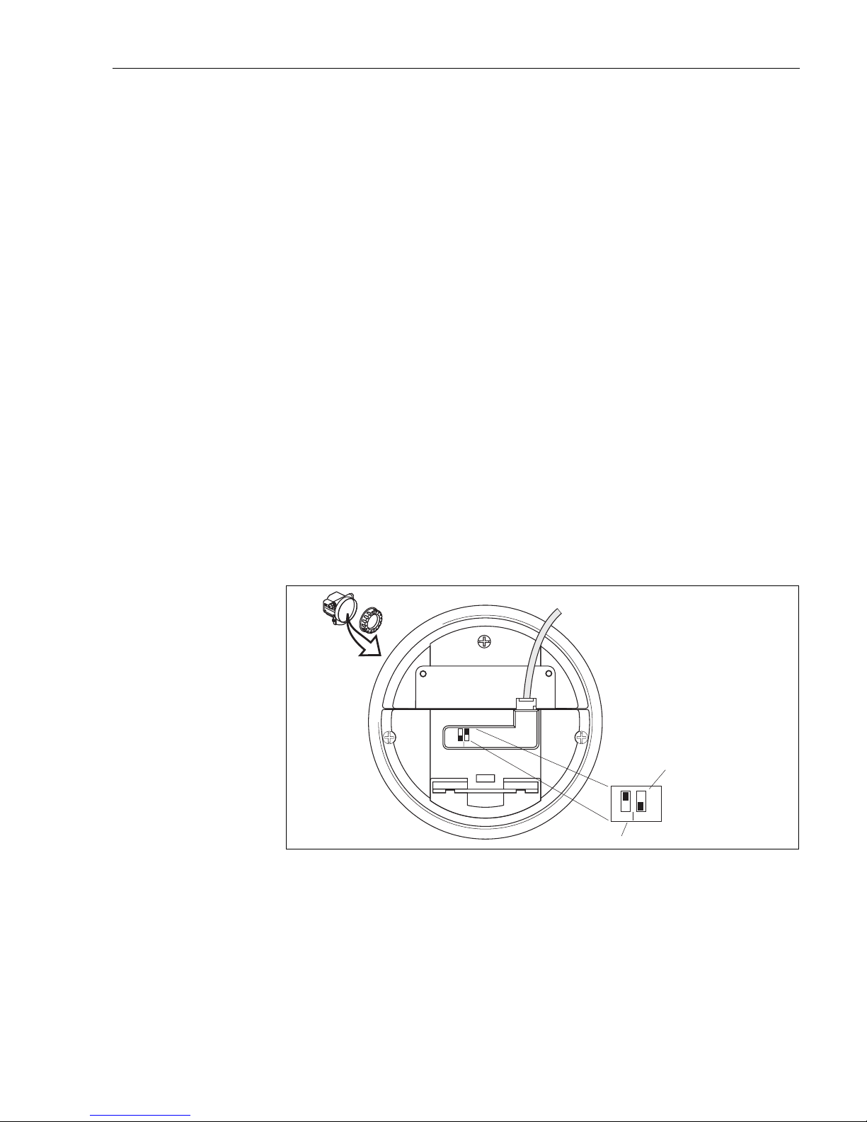
Locking and unlocking
L00-FMxxxxxx-19-00-00-en-002
WP = on: parametrization locked
WP = off: parametrization unlocked
SIM = on: simulation possible in Analog Input Block by configuration tool
SIM = off: simulation not possible in Analog Input Block by configuration tool
Parameters affected
Locking by the DIP switch affects all parameters.
E
ND
RES
S+HA
USER
MICR
OPILO
T II
ENDRESS+HAUSER
MICROPILOT II
IP 65
IP 65
O
rd
er C
o
d
e
:
S
er
.-N
o
.:
Order Code:
Ser.-No.:
M
e
s
s
b
e
reic
h
M
easur
ing r
an
ge
Messbereich
Measuring range
U
1
6
...3
6
V
D
C
4...20 m
A
U 16...36V DC
4...20 mA
m
a
x.
2
0
m
max.20 m
Made in Germany Maulburg
Made in Germany Maulburg
T>
7
0
°C
:
A
t >85
°C
T>70°C :
A
t >85°C
on
off
SIM WP
SIM WP
off
on
simulation
write protection
default settings:
write protection OFF
simulation ON (i.e. simulation is
allowed in the configuration tool)
Page 42
Commissioning Micropilot M FMR231 with FOUNDATION Fieldbus
42 Endress+Hauser
6.2.2 Key combination (display and operating module VU331)
Locking
Press S, O and F simultaneously.
Unlocking
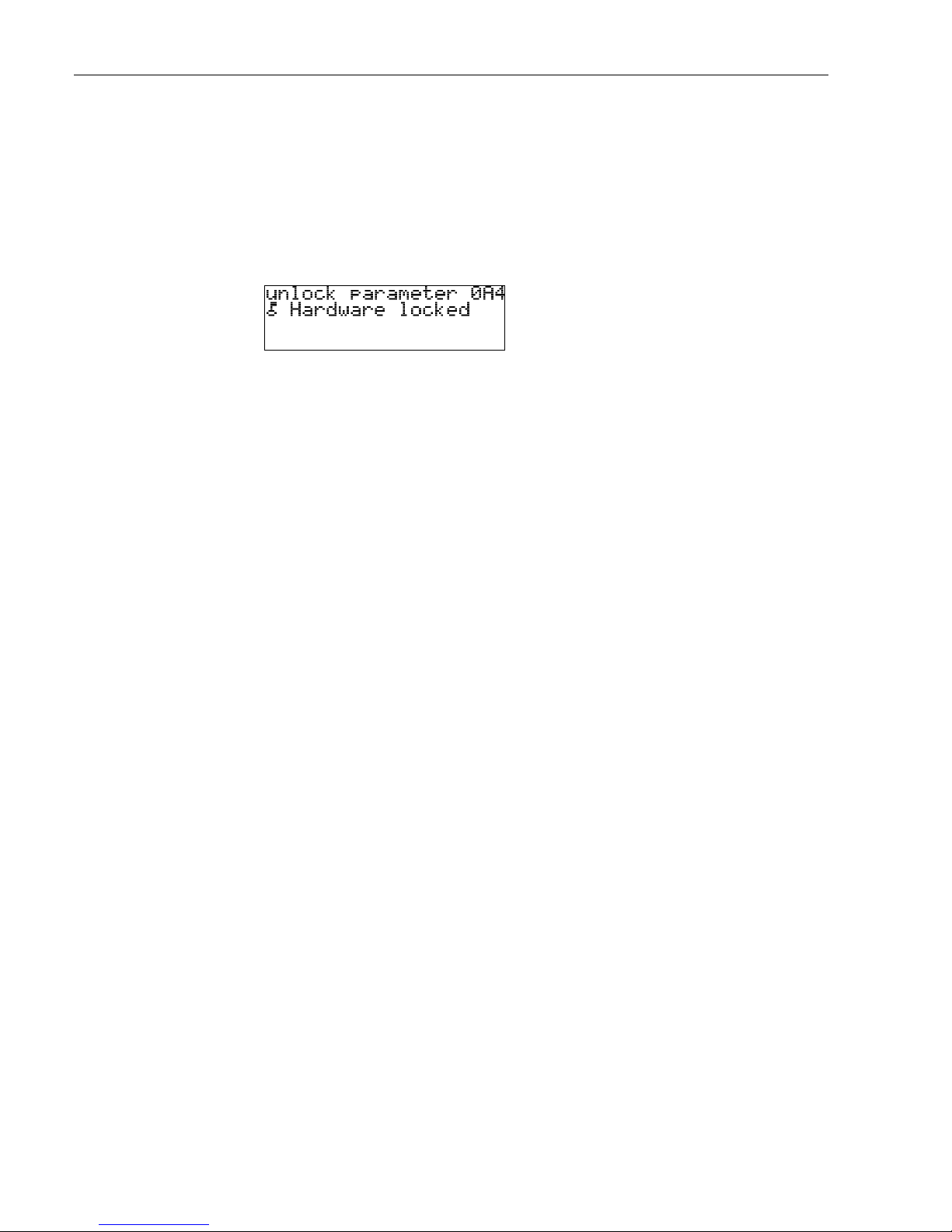
If you try to change a parameter, the following appears:
Press S, O and F simultaneously. The "unlock parameter" (0A4) function appears.
Enter "2457". Now parameters can be changed.
Parameters affected
Locking by the key combination affects the following parameters:
• Parameters of the device specific blocks (Sensor Block, Diagnostic Block, Display Block)
• Endress+Hauser service parameters
6.2.3 Locking parameter
Locking
Enter a number other than "2457" into the "unlock parameter" (0A4) function.
(FOUNDATION Fieldbus: Diagnsotic Block, parameter PAROPERATIONMODE)
Unlocking
Enter "2457" into the "unlock parameter" (0A4) function.
(FOUNDATION Fieldbus: Diagnostic Block, parameter PAROPERATIONMODE)
Parameters affected
Locking by the locking parameter affects the following parameters:
• Parameters of the device specific blocks (Sensor Block, Diagnostic Block, Display Block)
• Endress+Hauser service parameters
L00-fmrxf0a4-20-00-00-de-001
Page 43
Micropilot M FMR231 with FOUNDATION Fieldbus Commissioning
Endress+Hauser 43
6.3 Resetting the device
It is advisable to reset the device parameters before the commissioning if you want to use a device
with an unknown history.
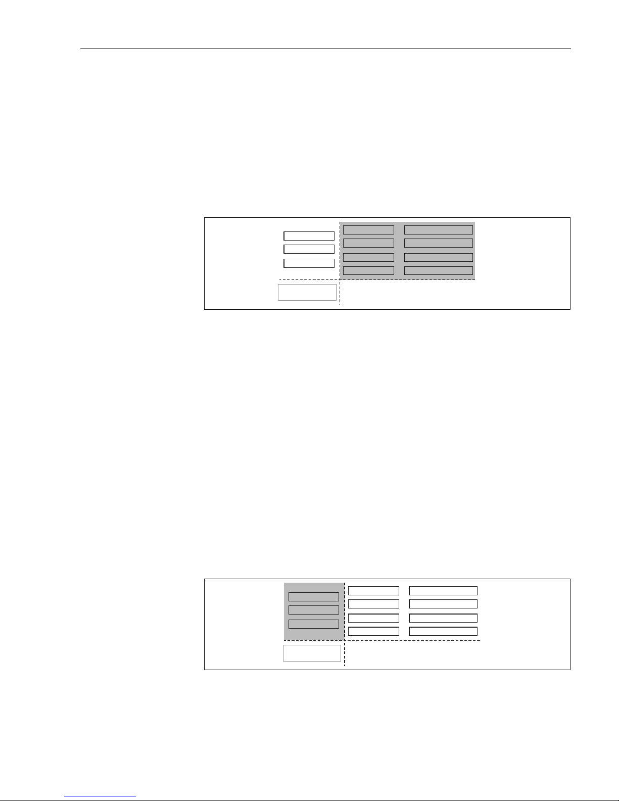
6.3.1 Resetting the parameters of the FOUNDATION Fieldbus function blocks
Parameters affected
• all parameters of the FOUNDATION Fieldbus function blocks
L00-FMU4XXXX-02-00-00-YY-007
Performing the reset
Resource Block, parameter RESTART; select the option "defaults".
6.3.2 Resetting the parameters of the transducer blocks
"
Caution!
A reset may lead to impairment of the measurement. As a rule, a basic calibration is required after
a reset.
!
Note!
The default values of each parameter are shown in bold in the menu overview in the appendix.
In order to carry out the reset, enter the number "33333" in the "reset" (0A3) function in the
"diagnostics" (0A) function group.
(FOUNDATION Fieldbus: Diagnostic Block, Parameter PARRESET (reset))
Parameters affected
• all parameters of the device specific blocks (Sensor Block, Diagnostic Block, Display Block)
L00-FMU4XXXX-02-00-00-YY-008
Effects of the reset
• All customer parameters are reset to their default values.
• Customer interference echo suppression is not deleted.
Endress+Hauser
Service-Parameter
Sensorblock
Diagnoseblock
Display-Block
Resource Block
AI-Block 1
AI-Block 2
PID Block
Arithmetik-Block
Input-Selector-Block
Signal-Charact.-Block
Integrator-Block
Endress+Hauser
Service-Parameter
Sensorblock
Diagnoseblock
Display-Block
Resource Block
AI-Block 1
AI-Block 2
PID Block
Arithmetik-Block
Input-Selector-Block
Signal-Charact.-Block
Integrator-Block
Page 44

Commissioning Micropilot M FMR231 with FOUNDATION Fieldbus
44 Endress+Hauser
• Linearisation is switched to "linear", but the table values are kept. The table can be switched
back on in the "linearisation" (04) function group in the "linearisation" (041) function.
(FOUNDATION Fieldbus: Sensor Block, Parameter PARLINEARISATION (linearisation))
Performing the reset
"diagnostics" (0A) function group, "reset" (0A3) function; enter "33333"
(FOUNDATION Fieldbus: Diagnostic Block, parameter PARRESET)
6.3.3 Resetting an interference echo suppression (tank map)
It is always adivable to reset the interference echo suppression (tank mapping) when:
• a device with an unknown history is used
• an incorrect suppression was input
Resetting the tank map with the VU331
1. In the "extended calibr." (05) function group select the "selection" (050) function.
2. Select "extended map."
3. Go to the "cust. tank map" (055) function and select the required option:
– "reset": deletes the existing tank map.
– "inactive": deactivates the tank map but does not delete it. It can be re-activated when
required.
– "active": activates the tank map.
Resetting the tank map with an Endress+Hauser operating program
1. In the function group "extended calibr." select the "cust. tank map" (055) function.
2. Select the required option ("reset", "inactive" or "active")
Resetting the tank map with a FOUNDATION Fieldbus configuration tool
1. In the Sensor Block select the parameter PARCUSTTANKMAP (cust tank map).
2. Select the required option ("reset", "inactive" or "active").
Page 45
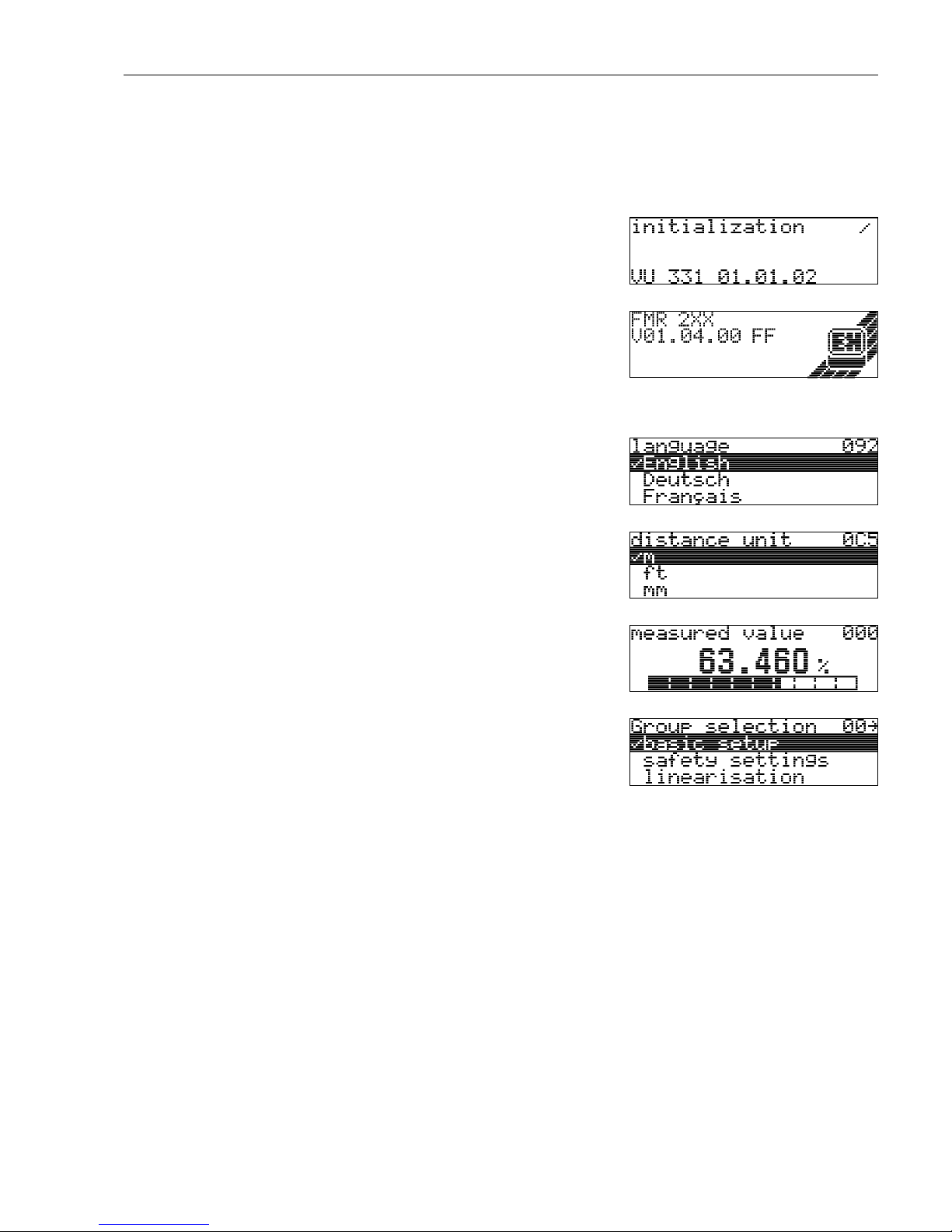
Micropilot M FMR231 with FOUNDATION Fieldbus Commissioning
Endress+Hauser 45
6.4 Commissioning by the display and operatig module
VU331
6.4.1 Power up instrument
The "Basic setup" (00) function group lists all the functions which are required for a standard
measurement task to commission the Prosonic M. When you have completed your input for a
function, the next function appears automatically. In this way, you are guided through the complete
calibration.
After switching on the supply voltage, the
instrument is first initialised.
L00-fmp-fxxx-20-00-00-en-003
Then the following appear for approximately
five seconds:
• Device type
•Software version
• Type of digital communication signal
Press F to exit this display.
L00-fmuxfxxx-20-00-00-de-002
On first power-up, you are requested to select
the language for the display texts.
L00-fmrxf092-20-00-00-en-001
Then you are requested to select the unit of
length for your measurements.
L00-fmrxf0c5-20-00-00-en-001
A measured value is displayed. This is NOT
equivalent to the level in your tank. Firstly carry
out a basic calibration.
L00-fmrxf000-20-00-00-en-001
Press F to switch to the group selection.
Press F again to start the basic calibration.
L00-fmrxfg00-20-00-00-en-001
Page 46
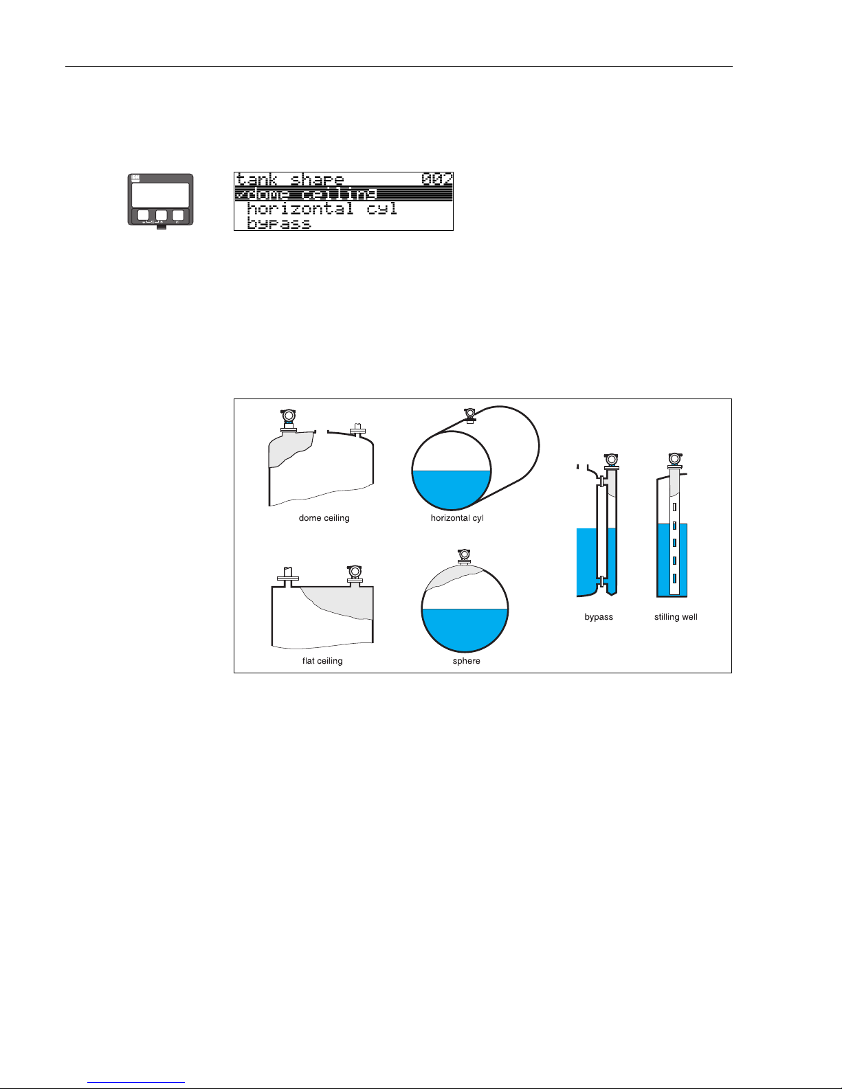
Commissioning Micropilot M FMR231 with FOUNDATION Fieldbus
46 Endress+Hauser
6.4.2 Application parameters
Function "tank shape" (002)
This function is used to select the tank shape.
Selection:
• dome ceiling
• horizontal cyl
•bypass
• stilling well
• flat ceiling
•sphere
L00-FMR2xxxx-14-00-06-en-007
⇒
ENDRESS + HAUSER
E
+
–
Page 47
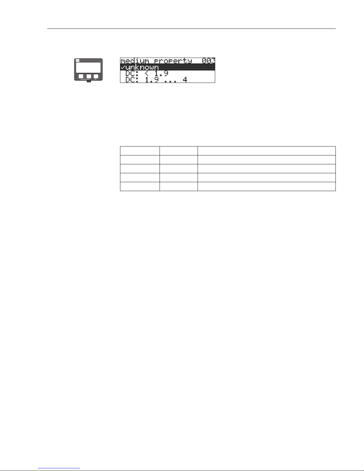
Micropilot M FMR231 with FOUNDATION Fieldbus Commissioning
Endress+Hauser 47
Function "medium property" (003)
This function is used to select the dielectric constant.
Selection:
• unknown
•DC: < 1.9
• DC: 1.9 ... 4
• DC: 4 ... 10
•DC: > 10
⇒
ENDRESS + HAUSER
E
+
–
Product class DC (εr) Examples
A 1,4...1,9 non-conducting liquids, e.g. liquefied gas
1)
1) Treat Ammonia NH3 as a medium of group A, i.e. use FMR 230 in a stilling well.
B 1,9...4 non-conducting liquids, e.g. benzene, oil, toluene, …
C 4...10 e.g. concentrated acids, organic solvents, esters, aniline, alcohol, acetone, …
D >10 conducting liquids, e.g. aqueous solutions, dilute acids and alkalis
Page 48
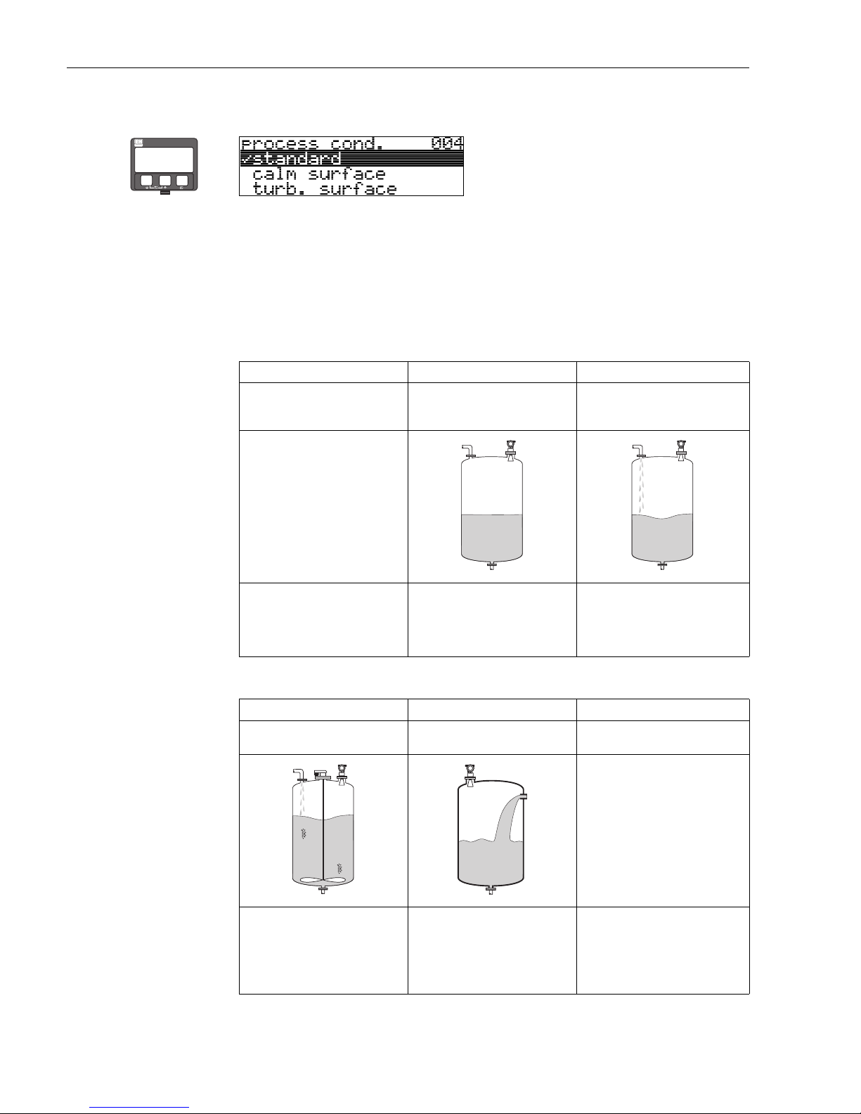
Commissioning Micropilot M FMR231 with FOUNDATION Fieldbus
48 Endress+Hauser
Function "process cond." (004)
This function is used to select the process conditions.
Selection:
• standard
• calm surface
• turb. surface
• agitator
• fast change
• test:no filter
⇒
ENDRESS + HAUSER
E
+
–
standard calm surface turb. surface
For all applications that do not fit into
any of the following groups.
Storage tanks with immersion tube or
bottom filling
Storage / buffer tanks with rough
surface due to free filling or mixer
nozzles
The filter and output damping are set
to average values.
The averaging filters and output
damping are set to high values.
→ steady meas. value
→ precise measurement
→ slower reaction time
Special filters to smooth the input
signals are emphasised.
→ smoothed meas. value
→ medium fast reaction time
agitator fast change test:no filter
Agitated surfaces (with possible
vortex) due to agitators
Rapid change of level, particularly in
small tanks
All filters can be switched off for service
/ diagnostic purposes.
Special filters to smooth the input
signals are set to high values.
→ smoothed meas. value
→ medium fast reaction time
→ minimization of effects by agitator
blades
The averaging filters are set to low
values. The output damping is set to 0.
→ rapid reaction time
→ possibly unsteady meas. value
All filters off.
Page 49
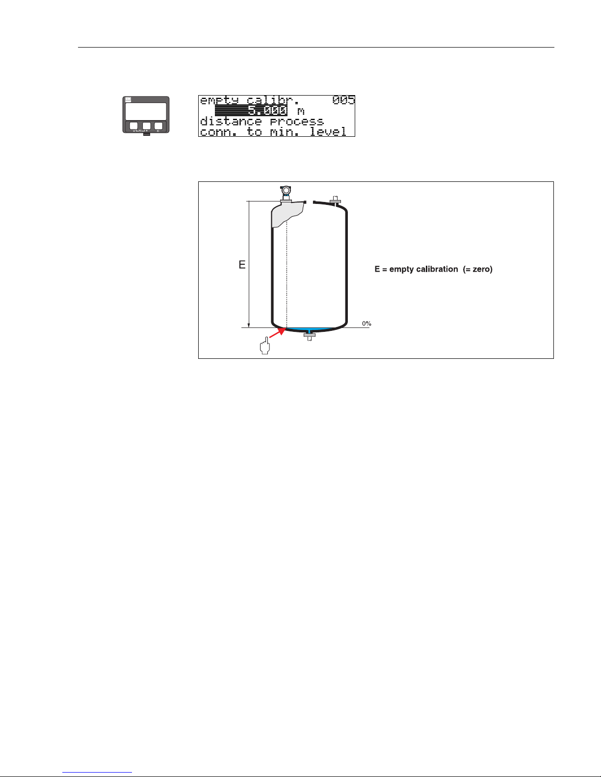
Micropilot M FMR231 with FOUNDATION Fieldbus Commissioning
Endress+Hauser 49
Function "empty calibr." (005)
This function is used to enter the distance from the flange (reference point of the measurement) to
the minimum level (=zero).
L00-FMR2xxxx-14-00-06-en-008
"
Caution!
For dish bottoms or conical outlets, the zero point should be no lower than the point at which the
radar beam hits the bottom of the tank.
⇒
ENDRESS + HAUSER
E
+
–
Page 50
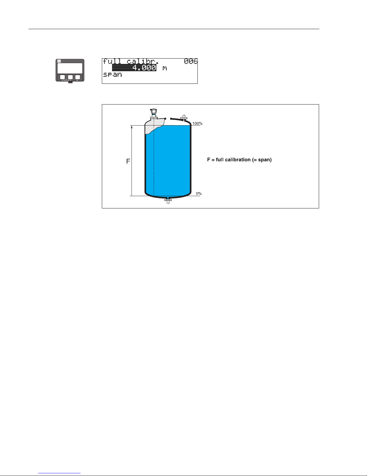
Commissioning Micropilot M FMR231 with FOUNDATION Fieldbus
50 Endress+Hauser
Function "full calibr." (006)
This function is used to enter the distance from the minimum level to the maximum level (=span).
L00-FMR2xxxx-14-00-06-en-009
!
Note!
If bypass or stilling well was selected in the "tank shape" (002) function, the pipe diameter is
requested in the following step.
In principle, it is possible to measure up to the tip of the antenna. However, due to considerations
regarding corrosion and build-up, the end of the measuring range should not be chosen any closer
than 50 mm (2”) to the tip of the antenna.
⇒
ENDRESS + HAUSER
E
+
–
Page 51
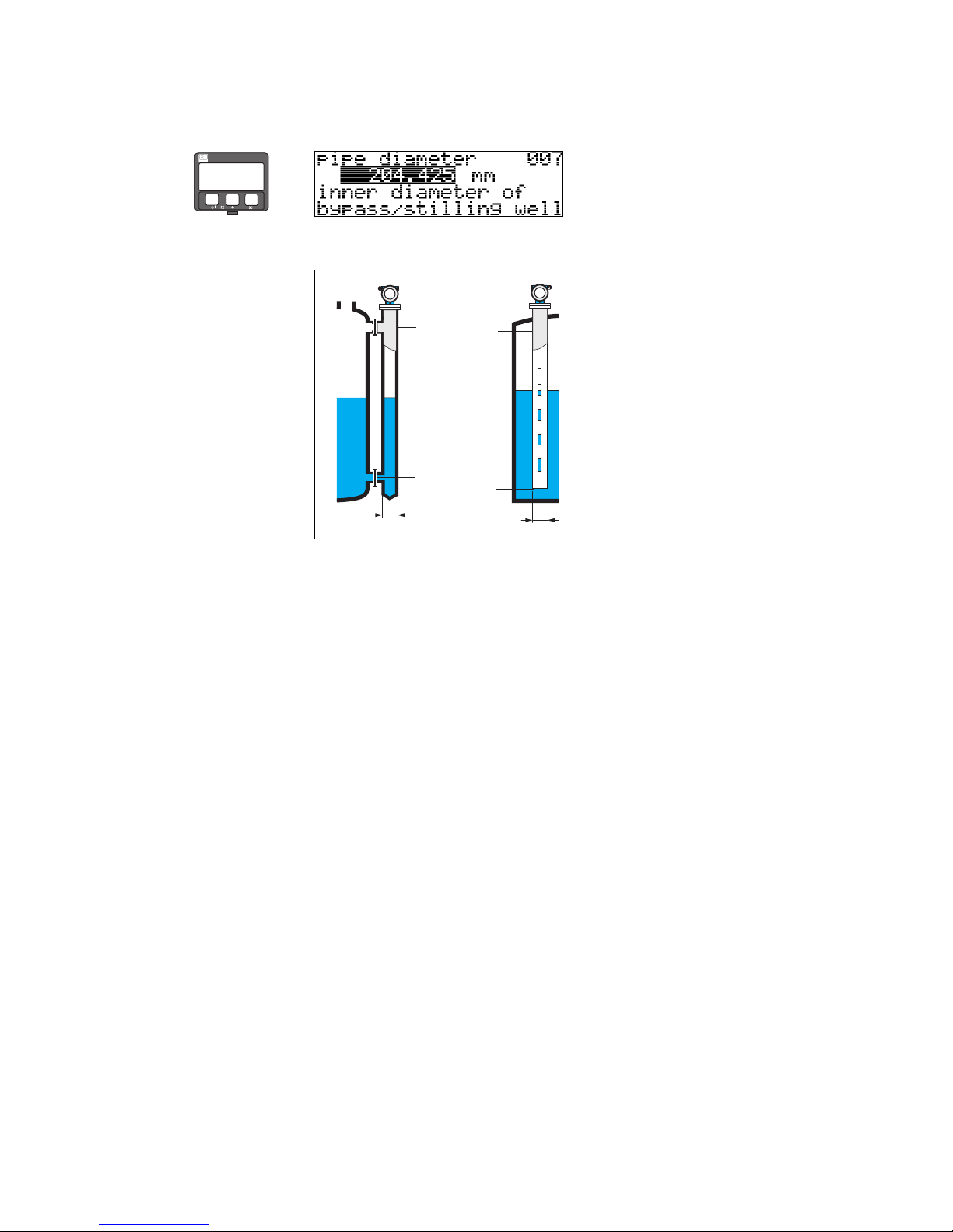
Micropilot M FMR231 with FOUNDATION Fieldbus Commissioning
Endress+Hauser 51
Function "pipe diameter" (007)
This function is used to enter the pipe diameter of the stilling well or bypass pipe.
L00-FMR2xxxx-14-00-00-en-011
Microwaves propagate more slowly in pipes than in free space. This effect depends on the inside
diameter of the pipe and is automatically taken into account by the Micropilot. It is only necessary
to enter the pipe diameter for applications in a bypass or stilling well.
⇒
ENDRESS + HAUSER
E
+
–
100%
0%
ø
100%
0%
ø
Page 52
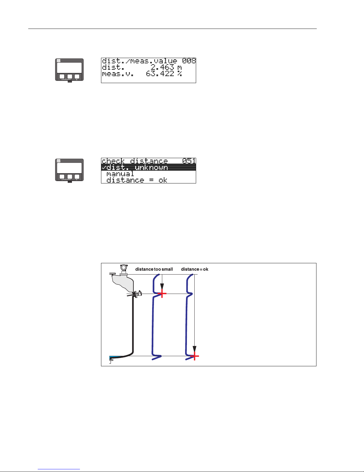
Commissioning Micropilot M FMR231 with FOUNDATION Fieldbus
52 Endress+Hauser
display (008)
The distance measured from the reference point to the product surface and the level calculated
with the aid of the empty adjustment are displayed. Check whether the values correspond to the
actual level or the actual distance. The following cases can occur:
• Distance correct − level correct → continue with the next function, "check distance" (051)
• Distance correct − level incorrect → Check "empty calibr." (005)
• Distance incorrect − level incorrect → continue with the next function, "check distance" (051)
Function "check distance" (051)
This function triggers the mapping of interference echoes. To do so, the measured distance must be
compared with the actual distance to the product surface. The following options are available for
selection:
Selection:
•distance = ok
• dist. too small
• dist. too big
• dist. unknown
• manual
L00_FMR2xxxxx-14-00-06-en-010
distance = ok
• mapping is carried out up to the currently measured echo
• The range to be suppressed is suggested in the "range of mapping" (052) function
Anyway, it is wise to carry out a mapping even in this case.
dist. too small
• At the moment, an interference is being evaluated
• Therefore, a mapping is carried out including the presently measured echoes
• The range to be suppressed is suggested in the "range of mapping" (052) function
⇒
ENDRESS + HAUSER
E
+
–
⇒
ENDRESS + HAUSER
E
+
–
Page 53
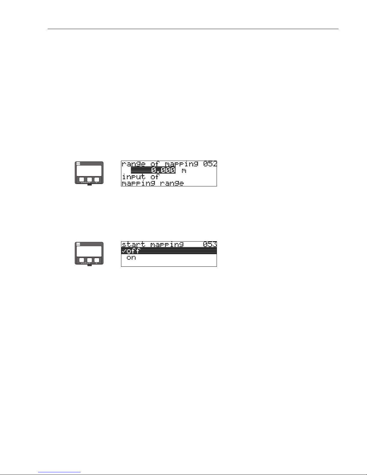
Micropilot M FMR231 with FOUNDATION Fieldbus Commissioning
Endress+Hauser 53
dist. too big
• This error cannot be remedied by interference echo mapping
• Check the application parameters (002), (003), (004) and "empty calibr." (005)
dist. unknown
If the actual distance is not known, no mapping can be carried out.
manual
A mapping is also possible by manual entry of the range to be suppressed. This entry is made in the
"range of mapping" (052) function.
"
Caution!
The range of mapping must end 0.5 m (20") before the echo of the actual level. For an empty tank,
do not enter E, but E – 0.5 m (20").
If a mapping already exists, it is overwriten up to the distance specified in
"range of mapping" (052). Beyond this value the existing mapping remains unchanged.
Function "range of mapping" (052)
This function displays the suggested range of mapping. The reference point is always the reference
point of the measurement (). This value can be edited by the operator.
For manual mapping, the default value is 0 m.
Function "start mapping" (053)
This function is used to start the interference echo mapping up to the distance given in "range of
mapping" (052).
Selection:
• off → no mapping is carried out
•on → mapping is started
During the mapping process the message "record mapping" is displayed.
"
Caution!
A mapping will be recorded only, if the device is not in alarm-state.
⇒
ENDRESS + HAUSER
E
+
–
⇒
ENDRESS + HAUSER
E
+
–
Page 54
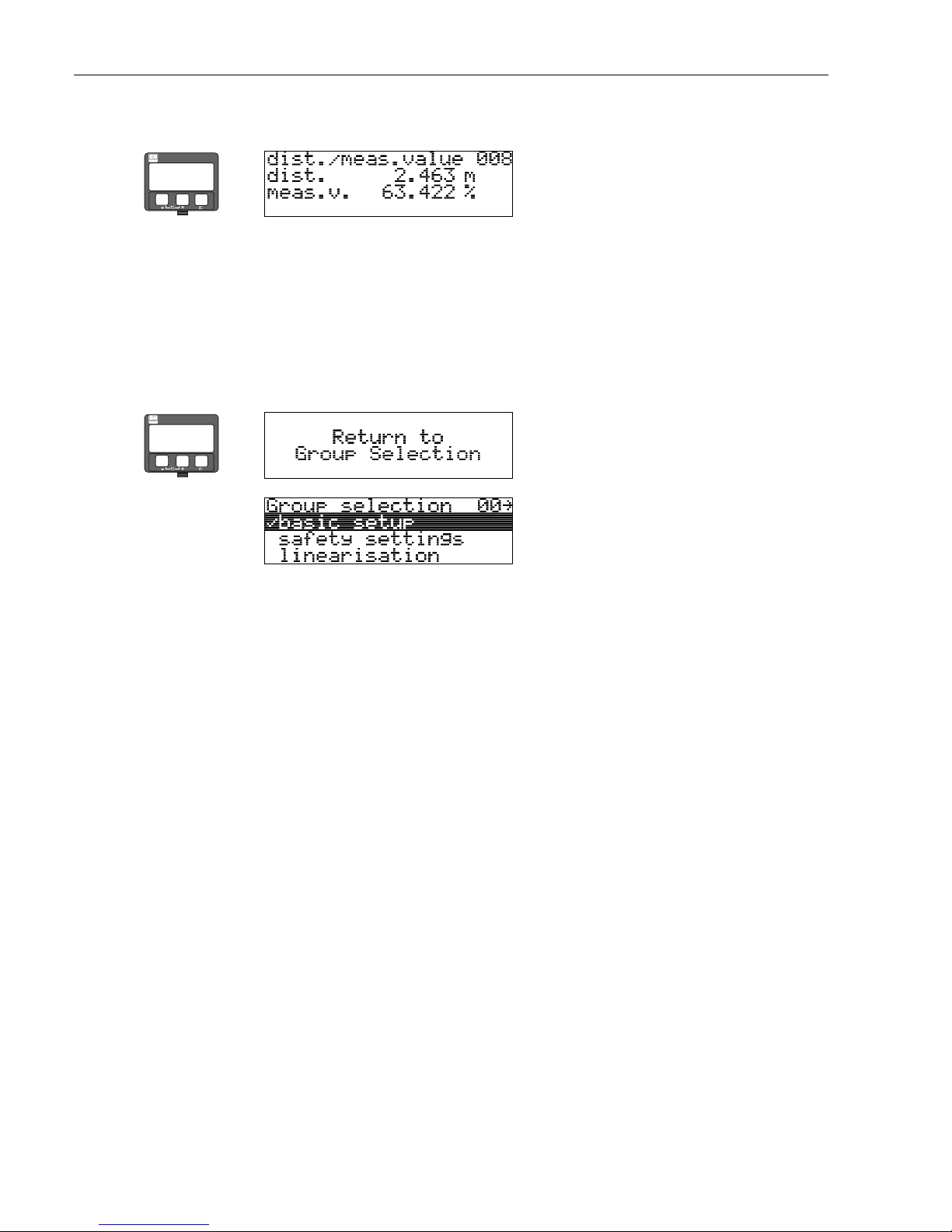
Commissioning Micropilot M FMR231 with FOUNDATION Fieldbus
54 Endress+Hauser
display (008)
The distance measured from the reference point to the product surface and the level calculated
with the aid of the empty adjustment are displayed. Check whether the values correspond to the
actual level or the actual distance. The following cases can occur:
• Distance correct − level correct → continue with the next function, "check distance" (051)
• Distance correct − level incorrect → Check "empty calibr." (005)
• Distance incorrect − level incorrect → continue with the next function, "check distance" (051)
⇒
ENDRESS + HAUSER
E
+
–
⇒
⇓
After 3 s, the following message appears
ENDRESS + HAUSER
E
+
–
Page 55
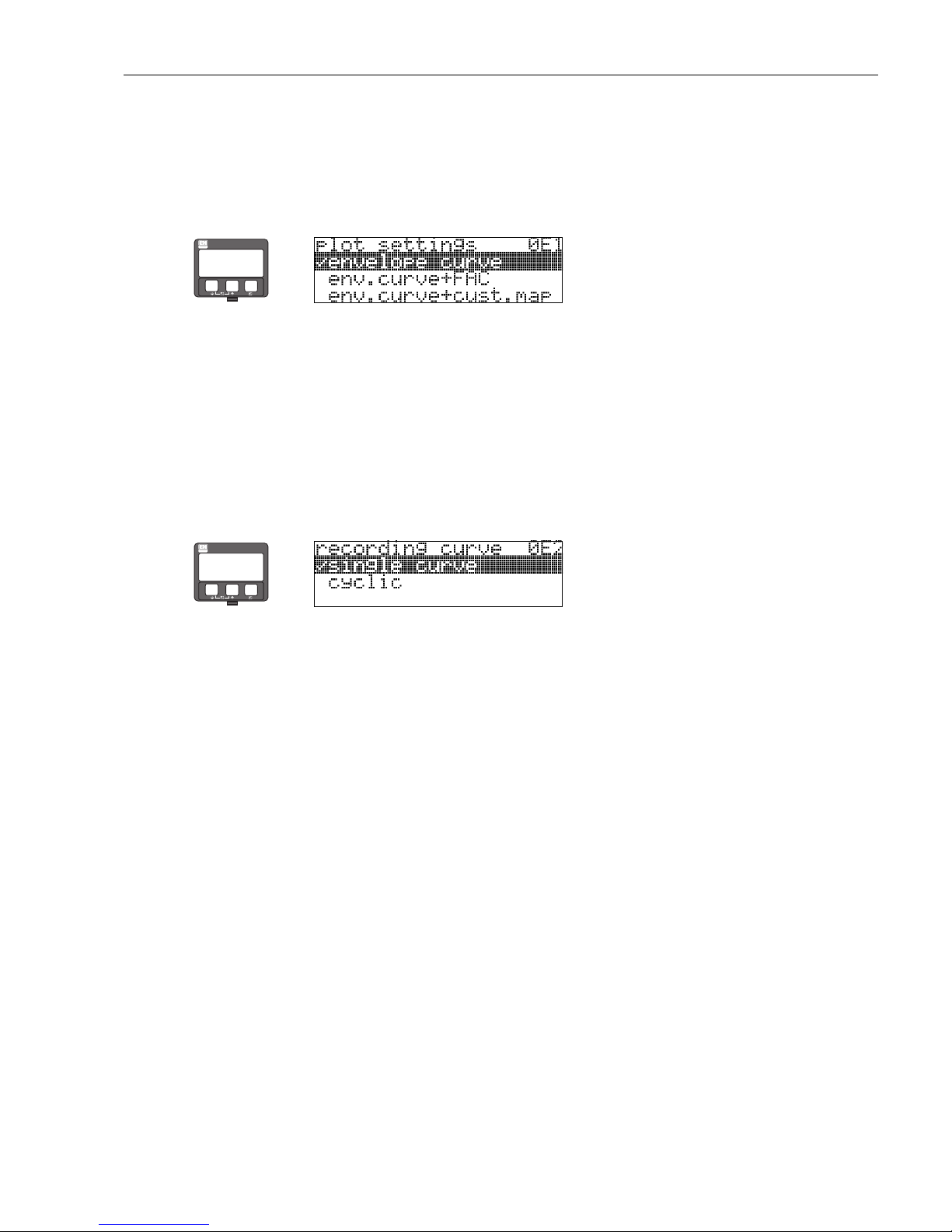
Micropilot M FMR231 with FOUNDATION Fieldbus Commissioning
Endress+Hauser 55
6.4.3 Envelope curve
After the basic setup, an evaluation of the measurement with the aid of the envelope curve
("envelope curve" (0E) function group) is recommended.
Function "plot settings" (0E1)
Select which information will be displayed in the LCD:
• envelope curve
• env.curve+FAC (on FAC see BA221F)
• env.curve+cust.map (i.e. customer tank map is also displayed)
Function "recording curve" (0E2)
This function defines whether the envelope curve is read as a
• single curve
or
• cyclic.
!
Note!
If the cyclical envelope curve is active in the display, the measured value is refreshed in a slower
cycle time. It is therefore recommended to exit the envelope curve display after optimising the
measuring point.
!
Note!
An orientation of the Micropilot can help to optimise measurement in applications with very weak
level echos or strong interference echos by increasing the useful echo/reducing the interference
echo (see "Orientation of the Micropilot" on Page 79).
⇒
ENDRESS + HAUSER
E
+
–
⇒
ENDRESS + HAUSER
E
+
–
Page 56
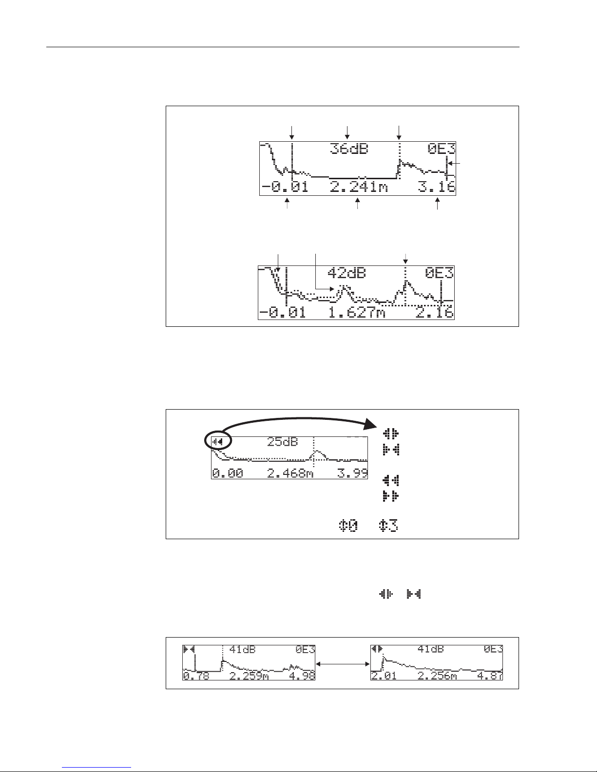
Commissioning Micropilot M FMR231 with FOUNDATION Fieldbus
56 Endress+Hauser
Function "envelope curve display" (0E3)
The envelope curve is displayed in this function. You can use it to obtain the following information:
L00-FMU4xxxx-07-00-00-en-003
Navigating in the envelope curve display
Using navigation, the envelope curve can be scaled horizontally and vertically and shifted to the left
or the right. The active navigation mode is indicated by a symbol in the top left hand corner of the
display.
L00-FMxxxxxx-07-00-00-en-004
Horizontal Zoom mode
Firstly, go into the envelope curve display. Then press
O
or S to switch to the envelope curve
navigation. You are then in Horizontal Zoom mode. Either or is displayed.
•
O
increases the horizontal scale.
•
S
reduces the horizontal scale.
L00-FMxxxxxx-07-00-00-yy-007
minimum distance
of the plot
maximum distance
of the plot
distance of
evaluated echo
interference echo
evaluated echo
is marked
quality of
evaluated echo
empty calibr.
envelope curve
only
envelope curve and
interference echo
suppression (map)
level echo
map
full calibr.
…
OE3
Move mode:
- m-oved to the left
moved to the right
Horizontal Zoom mode:
- h-orizontal zoom in
horizontal zoom out
Vertical Zoom mode:
- vertical zoom (4 steps)
O
S
Page 57
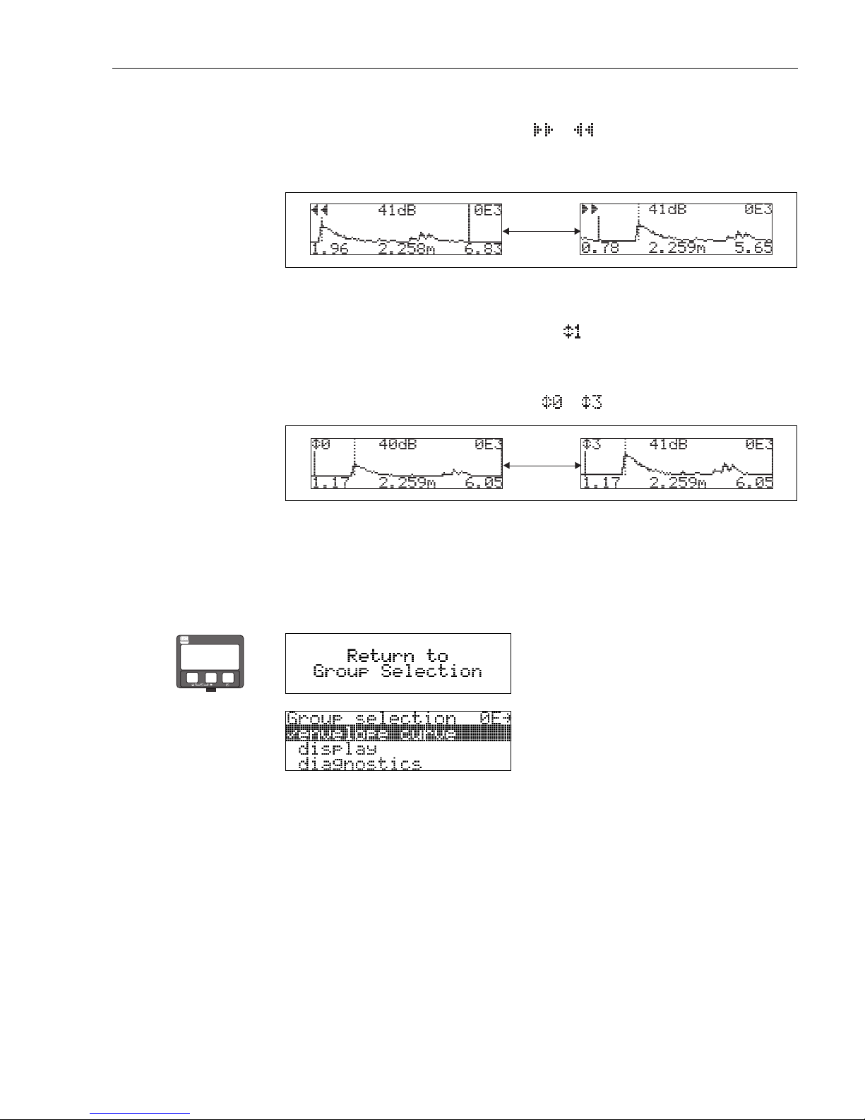
Micropilot M FMR231 with FOUNDATION Fieldbus Commissioning
Endress+Hauser 57
Move mode
Then press
F
to switch to Move mode. Either or is displayed.
•
O
shifts the curve to the right.
•
S
shifts the curve to the left.
L00-FMxxxxxx-07-00-00-yy-008
Vertical Zoom mode
Press
F
once more to switc h to Ver tical Zoom mode. is d isplay ed. You now hav e the follo wing
options.
•
O
increases the vertical scale.
•
S
reduces the vertical scale.
The display icon shows the current zoom factor ( to ).
L00-FMxxxxxx-07-00-00-yy-009
Exiting the navigation
•Press
F
again to run through the different modes of the envelope curve navigation.
•Press
O
and S to exit the navigation. The set increases and shifts are retained. Only when you
reactivate the "recording curve" (0E2) function the Micropilot uses the standard display again.
O
S
O
S
⇒
⇓
After 3 s, the following message appears
ENDRESS + HAUSER
E
+
–
Page 58
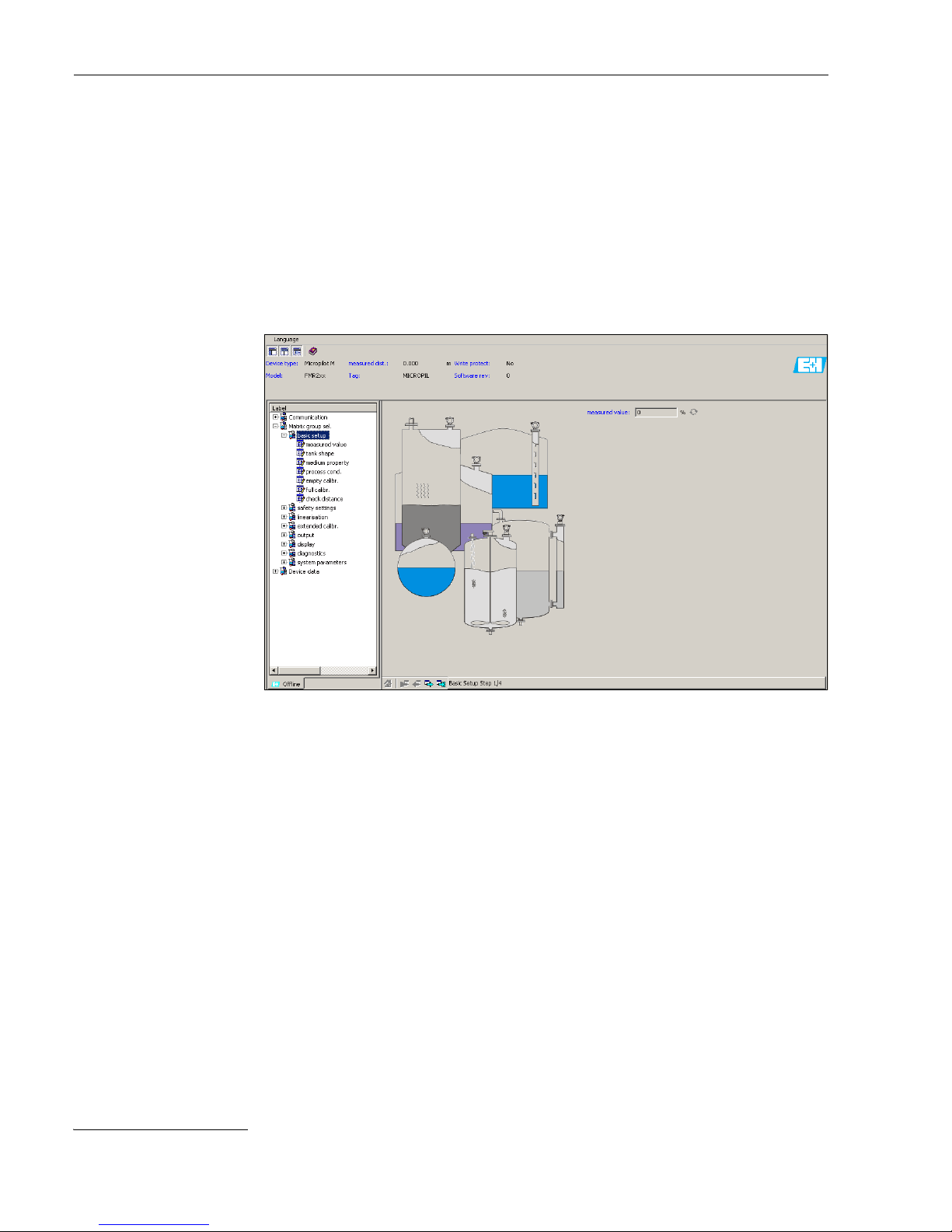
Commissioning Micropilot M FMR231 with FOUNDATION Fieldbus
58 Endress+Hauser
6.5 Basic Setup with the Endress+Hauser operating
program
To carry out the basic setup with the operating program, proceed as follows:
• Start the operating program and establish a connection.
2)
• Select the "basic setup" function group in the navigation window.
The following display appears on the screen:
Basic Setup step 1/4:
• measured value
MicropilotM-en-301
•The "Next" button moves you to the next screen display:
!
Note!
Each parameter that is changed must be confirmed with the RETURN key!
2) If the connection can not be established, make sure that you use the latest versin of the operating program.
Page 59
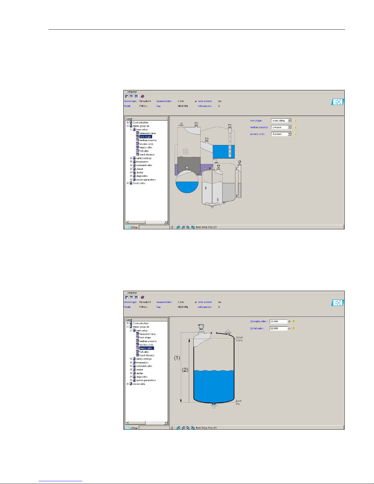
Micropilot M FMR231 with FOUNDATION Fieldbus Commissioning
Endress+Hauser 59
Basic Setup step 2/4:
• Enter the application parameters:
– tank shape
– medium property
– process cond.
MicropilotM-en-302
Basic Setup step 3/4:
If "dome ceiling", "horizontal cyl", "..." is selected in the "tank shape" function, the following
display appears on the screen:
• empty calibr.
• full calibr.
MicropilotM-en-303
Page 60
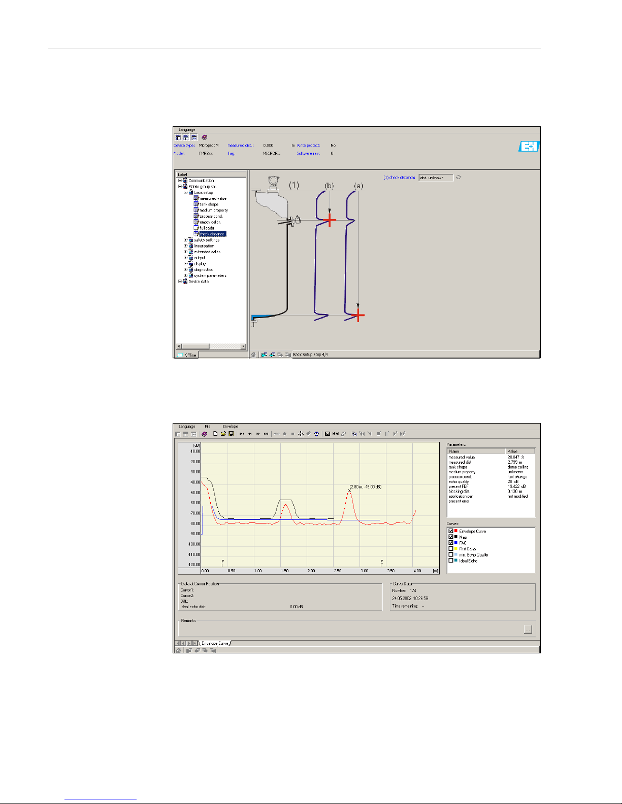
Commissioning Micropilot M FMR231 with FOUNDATION Fieldbus
60 Endress+Hauser
Basic Setup step 4/4:
• This step starts the tank mapping
• The measured distance and the current measured value are always displayed in the header
MicropilotM-en-304
6.5.1 Signal analysis via envelope curve
After the basic setup, an evaluation of the measurement using the envelope curve is recommended.
MicropilotM-en-306
Page 61

Micropilot M FMR231 with FOUNDATION Fieldbus Commissioning
Endress+Hauser 61
6.5.2 User-specific applications (operation)
For details of setting the parameters of user-specific applications, see separate documentation
BA221F/00/en "Micropilot M - Description of Instrument Functions" on the enclosed CD-ROM.
Page 62

Commissioning Micropilot M FMR231 with FOUNDATION Fieldbus
62 Endress+Hauser
6.6 Commissioning with a FOUNDATION Fieldbus
configuration tool
!
Note!
For commissioning of the device with a FOUNDATION Fieldbus configuration tool you need to
know the DEVICE_ID, which consists of the following parts:
whereby:
6.6.1 Fist setup
1. Open the configuration tool and load the Device Descriptions (*.ffo, *.sym and - if required by
the tool - *.cff). Ensure you use the correct files (see chapter 5.4).
2. The first time it is connected, the device reports as follows:
FMR24x-FF-in-NIConfig
3. Identify the device using the DEVICE_ID and assign the desired field device tag name
(PD_TAG).
Factory setting: PD_TAG = E+H_MICROPILOT_M_XXXXXXXX
Device_ID = 452B48100F-XXXXXXXX
452B48 ID code for Endress+Hauser
100F ID code for Micropilot M
XXXXXXXX Device serial number, as printed on the nameplate
Page 63

Micropilot M FMR231 with FOUNDATION Fieldbus Commissioning
Endress+Hauser 63
6.6.2 Parametrization of the Resource Block (Start Index: 400)
1. Enter the desired block name (optional).
Factory setting: RESOURCE_XXXXXXXX
2. Opern the Resource Block
3. On delivery, write protection is disabled so that you can access the write parameters via
FOUNDATION Fieldbus. Check this status by the parameter WRITE_LOCK:
– Write protectin activated: WRITE_LOCK = LOCKED
– Write protection deactivated: WRITE_LOCK = NOT LOCKED
Deactivate the write protection if necessary, see section 6.2.1.
4. Set the operating mode to AUTO in the parameter group MODE_BLK (parameter TARGET).
6.6.3 Parametrization of the Sensor Block (Start Index: 2000)
1. Enter the desired block name (optional)
Factory setting: SENSOR_BLOCK_XXXXXXXX
2. Open the Sensor Block. The following display appears:
FMR2xx-FF-Sensorblock-in-NIConfig
!
Hinweis!
There are two possibilities to edit the parameters of the block:
• A parameter from the list can be opened for editing by a double click.
• You can open one of the FOUNDATION Fieldbus methods. Each method guides you
automatically through a number of parameters which are required for a specific configuration
task. The following sections describe the parametrization by the "basic setup" method.
3. Open the FOUNDATION Fieldbus method "basic setup":
Page 64

Commissioning Micropilot M FMR231 with FOUNDATION Fieldbus
64 Endress+Hauser
FMR2xx-FF-Methode-in-NIConfig
4. The method contains the following parameters3):
a. Application parameters (see section 6.4.2)
– PARTANKSHAPE (tank shape)
– PARMEDIUMCONDITION (medium property)
– PARPROCESSCONDITION (process condition)
b. Empty and full calibration (see section 6.4.3)
– PAREMPTYCALIBRATION (empty calibration)
– PARFULlCALIBRATION (full calibration)
c. Interference echo suppression (see section 6.4.4)
– PARCHECKDISTANCE (check distance)
– PARSUPPRESSIONDISTANCE (range of mapping)
– PARSTARTMAPPINGRECORD (start maping)
– PARPRESMAPRANGE (pres. map. dist.)
– PARCUSTTANKMAP (cust. tank map)
5. Set the operating mode to AUTO in the parameter group MODE_BLK (parameter TARGET).
Otherwise the measured value can not be processed correctly by the connected Analog Input
Block.
6. If measuring errors occur or if the measuring value seems unreliable, it is advisable to check
the quality of the measurement by the envelope curve display. This can be done in two
different ways:
– by the display and operating module VU331 (see section 6.4.5)
– by an Endress+Hauser operating program (see section 6.5.1)
3) In the FOUNDATION Fieldbus configuration tool you can select from two types of parameter display:
- parameter names (e.g. "PARTANKSHAPE")
- label texts (e.g. "tank shape")
Page 65

Micropilot M FMR231 with FOUNDATION Fieldbus Commissioning
Endress+Hauser 65
6.6.4 Parametrization of the Analog Input Blocks
Prosonic M has two Analog Input Blocks that can be assigned to the various process variables. The
following descripiton provides an example for the Analog Input Block 1 (Start Index 500).
1. Enter the desired block name (optional).
Factory setting: ANALOG_INPUT_1_XXXXXXXX
2. Open the Analog Input Block.
3. Set the operating mode to OOS (Out of Service) in the parameter group MODE_BLK
(parameter TARGET).
4. Using the parameter CHANNEL select the process variable that is to be used as the input value
for the function block algorithm (scaling and limit value monitoring). The following settings
are possible:
–CHANNEL = 1: level
– CHANNEL = 2: distance
5. In the parameter gorup XD_SCALE select the desired engineering unit and the block input
range (measuring range) for the process variable in question (see the example below).
"
Caution!
Make sure that the selected unit is suitable for the measurement variable of the selected
process variable. Otherwies the parameter BLOCK_ERROR will display the error message
"Block Configuration Error" and the block operating mode cannot be set to AUTO.
6. In the L_TYPE prameter, select the mode of linearization for the input variable (Direct,
Indirect, Indirect Sq Root). For details refer to section 11.7 in the Appendix.
"
Caution!
Note that with the type of linearization "Direct" the configuration of the parameter group
OUT_SCALE must agree with the configuration of the parameter group XD_SCALE.
Otherwise the block operating mode cannot be set to AUTO. Such incorrect configuration is
indicated in the parameter BLOCK_ERROR by the "Block Configuration Error" message.
Example:
• The measuring range of the sensor is 0 to 10 m.
• The output range to the automation system should be 0 to 10 m, too.
The following settings are to be made:
• Analog Input Block 1, Parameter CHANNEL -> "1" (measured level)
• Parameter L_TYPE -> DIRECT
• Parameter group XD_SCALE
XD_SCALE 0% -> 0
XD_SCALE 100% -> 10
XD_SCALE_UNIT -> m
• Parameter group OUT_SCALE
OUT_SCALE 0% -> 0
OUT_SCALE 100% -> 10
OUT_SCALE_UNIT -> m
7. If required, use the following parameters to define the limit values for alarm and warning
messages:
– HI_HI_LIM -> Limit value for the upper alarm
– HI_LIM -> Limit value for the upper warning
– LO_LIM -> Limit value for the lower warning
– LO_LO_LIM -> Limit value for the lower alarm
The limit values entered must be within the value range specified in the parameter group
OUT_SCALE.
8. In addition to the limit values you must also specify the action taken if a limit value is exceeded
using the alarm priorities (parameters HI_HI_PRI, HI_PRI, LO_PRI, LO_LO_PRI). Reporting
to the the fieldbus host system only takes place if the alarm priority is higher than 2. For details
refer to section 11.7 in the Appendix.
Page 66
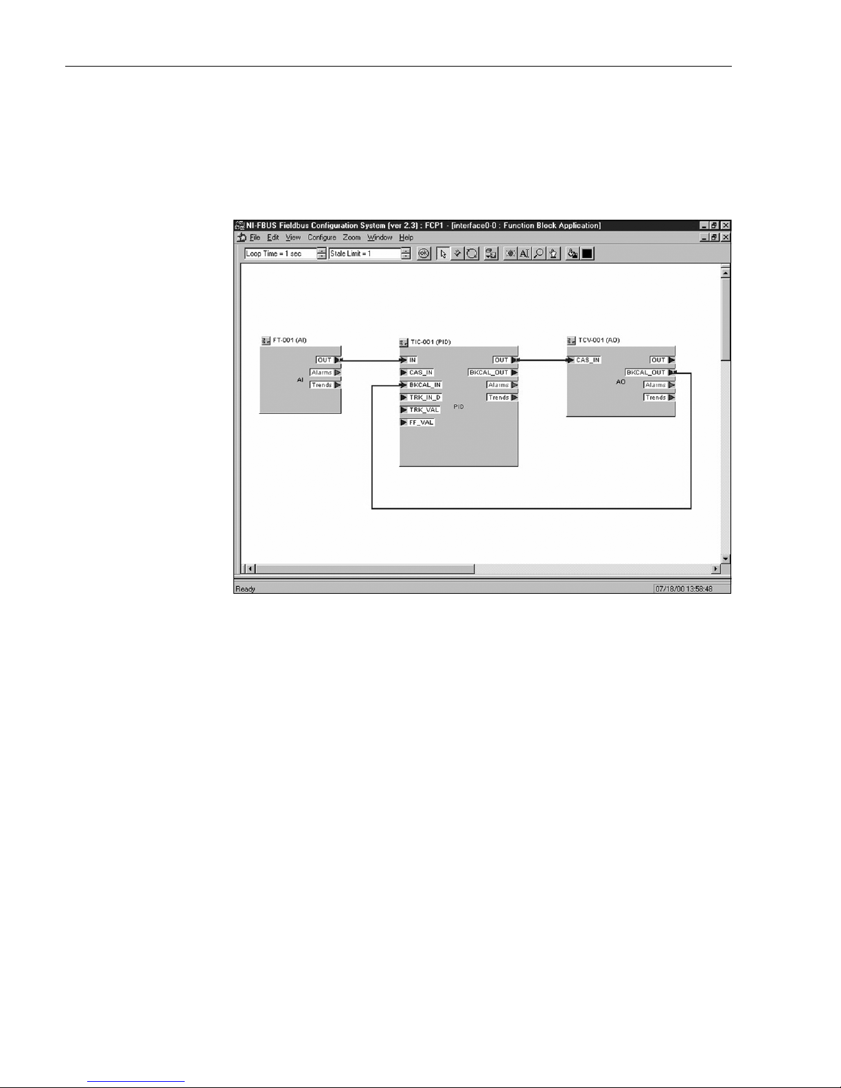
Commissioning Micropilot M FMR231 with FOUNDATION Fieldbus
66 Endress+Hauser
6.6.5 Connection of the function blocks
1. A concluding overall system configuration is essential so that the operating mode of the Analog
Input Block can be set to AUTO and so that the field device is integrated into the system
application. To do this, a configuration software (e.g. you host system software) is used to
connect the function blocks - normally graphically - to the desired control strategy and then
the sequence of the individual process control functions is specified.
NI-FBUS-FMxxx-en-001
Example: Connection of the function blocks with the NI-FBUS Configurator
2. Download the configuration data into the field devices by the download function of the
FOUNDATION Fieldbus configuration tool.
3. Set the oerating mode of the AI Block to AUTO (parameter group MODE_BLK, parameter
TARGET). However, this is only possible under the following conditions:
– The function blocks are correctly connected with each other.
– The parametrization of the AI Block is correct (see 6.6.4, steps 5 and 6).
– The Resource Block is in operating mode AUTO.
Page 67

Micropilot M FMR231 with FOUNDATION Fieldbus Commissioning
Endress+Hauser 67
6.7 Commissioning with the handheld terminal DXR375/
FC375
The steps of the commissioning procedure are the same as with a FOUNDATION Fieldbus
configuration tool (see chapter 6.6).
The blocks should be parametrized in the following order:
• the RESOURCE BLOCK
• the SENSOR BLOCK
(the "basic setup" method can be used for this, see section 5.5.4)
• the ANALOG INPUT BLOCKS
Page 68

Maintenance Micropilot M FMR231 with FOUNDATION Fieldbus
68 Endress+Hauser
7 Maintenance
The Micropilot M measuring instrument requires no special maintenance.
Exterior cleaning
When cleaning the exterior of measuring devices, always use cleaning agents that do not attack the
surface of the housing and the seals.
Replacing seals
The process seals of the sensors must be replaced periodically, particularly if molded seals (aseptic
construction) are used. The period between changes depends on the frequency of cleaning cycles
and on the temperature of the measured substance and the cleaning temperature.
Repairs
The Endress+Hauser repair concept assumes that the measuring devices have a modular design and
that customers are able to undertake repairs themselves. Spare parts are contained in suitable kits.
They contain the related replacement instructions. All the spare parts kits which you can order from
Endress+Hauser for repairs to the Micropilot M are listed with their order numbers on and . Please
contact Endress+Hauser Service for further information on service and spare parts.
Repairs to Ex-approved devices
When carrying out repairs to Ex-approved devices, please note the following:
• Repairs to Ex-approved devices may only be carried out by trained personnel or by
Endress+Hauser Service.
• Comply with the prevailing standards, national Ex-area regulations, safety instructions (XA) and
certificates.
• Only use original spare parts from Endress+Hauser.
• When ordering a spare part, please note the device designation on the nameplate. Only replace
parts with identical parts.
• Carry out repairs according to the instructions. On completion of repairs, carry our the specified
routine test on the device.
• Only Endress+Hauser Service may convert a certified device into a different certified variant.
• Document all repair work and conversions.
Replacement
After a complete Micropilot or electronic module has been replaced, the parameters can be
downloaded into the instrument again via the communication interface. Prerequisite to this is that
the data were uploaded to the PC beforehand using the ToF Tool / Commuwin II.
Measurement can continue without having to carry out a new setup.
• You may have to activate linearisation (see BA 221F on the enclosed CD-ROM)
• You may need to record the tank map again (see Basic Setup)
After an antenna component or electronic has been replaced, a new calibration must be carried out.
This is described in the repair instructions.
Page 69
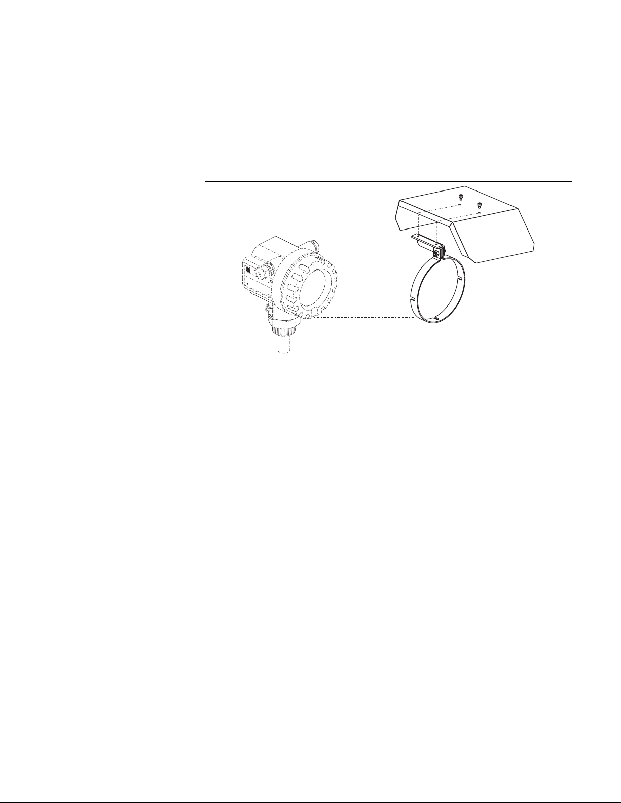
Micropilot M FMR231 with FOUNDATION Fieldbus Accessories
Endress+Hauser 69
8 Accessories
Various accessories, which can be ordered separately from Endress+Hauser, are available for the
Micropilot M.
Weather protection cover
A Weather protection cover made of stainless steel is recommended for outdoor mounting (order
code: 543199-0001). The shipment includes the protective cover and tension clamp.
L00-FMR2xxxx-00-00-06-en-001
Commubox FXA291
The Commubox FXA291 connects Endress+Hauser field instruments with CDI interface (=
Endress+Hauser Common Data Interface) to the USB interface of a personal computer or a
notebook. For details refer to TI405C/07/en.
!
Note!
For the following Endress+Hauser instruments you need the "ToF Adapter FXA291" as an additional
accessory:
• Cerabar S PMC71, PMP7x
• Deltabar S PMD7x, FMD7x
• Deltapilot S FMB70
• Gammapilot M FMG60
• Levelflex M FMP4x
• Micropilot FMR130/FMR131
• Micropilot M FMR2xx
• Micropilot S FMR53x, FMR540
• Prosonic FMU860/861/862
• Prosonic M FMU4x
• Tank Side Monitor NRF590 (with additional adapter cable)
ENDRESS+HAUSER
MICROPILOT II
ENDRESS+HAUSER
MICROPILOT II
IP 65
Order Code:
Ser.-No.:
Order Code:
Ser.-No.:
Messbereich
Measur
ing range
Messbereich
Measuring range
U 16...3
6
V DC
4...20 mA
U 16...36V DC
4...20 mA
max.
20 m
max.20 m
Made in Germany Maulburg
Made in Germany Maulburg
T>70°C :
A
t >85°C
T >70°C :
A
t >85°C
F12 / F23 / T12 housing
Page 70
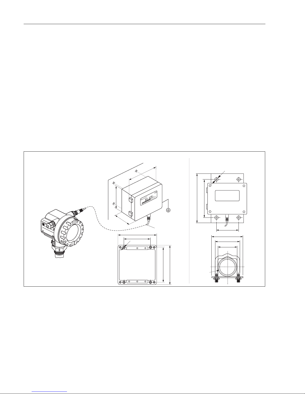
Accessories Micropilot M FMR231 with FOUNDATION Fieldbus
70 Endress+Hauser
ToF Adapter FXA291
The ToF Adapter FXA291 connects the Commubox FXA291 via the USB interface of a personal
computer or a notebook to the following Endress+Hauser instruments:
• Cerabar S PMC71, PMP7x
• Deltabar S PMD7x, FMD7x
• Deltapilot S FMB70
• Gammapilot M FMG60
• Levelflex M FMP4x
• Micropilot FMR130/FMR131
• Micropilot M FMR2xx
• Micropilot S FMR53x, FMR540
• Prosonic FMU860/861/862
• Prosonic M FMU4x
• Tank Side Monitor NRF590 (with additional adapter cable)
For details refer to KA271F/00/a2.
Remote display FHX40
L00-FMxxxxxx-00-00-06-en-003
ENDRESS+HA
USER
ENDRESS+HAUSER
IP 65
IP 65
Order Code:
Ser.-No.:
Order Code:
Ser.-No.:
Messbereich
Measuring range
Messbereich
Measuring range
U 16...36V DC
4...20 mA
U 16...36V DC
4...20 mA
max.20 m
max.20 m
Made in Germany Maulburg
Made in Germany Maulburg
T >70°C :
A
t >85°C
T >70°C :
A
t >85°C
82
6,3
106
122
120
max. 80
min. 30
96
88
160
8,5
118
180
Micropilot M
Levelflex M
Prosonic M
Separate housing
FHX 40 (IP 65)
Cable
122
150
80
Wall-mounting
(without mounting bracket)
Pipe-mounting
(mounting bracket and plate
supplied optionally,
s. product structure)
pipe
Page 71
Micropilot M FMR231 with FOUNDATION Fieldbus Accessories
Endress+Hauser 71
Technical data (cable and housing) and product structure:
For connection of the remote display FHX40 use the cable which fits the communication version of
the respective instrument.
Max. cable length 20 m (65 ft)
Temperature range -30 °C...+70 °C (-22 °F...158 °F)
Degree of protection IP65 acc. to EN 60529 (NEMA 4)
Materials Housing: AlSi12; cable glands: nickle plated brass
Dimensions [mm] / [inch] 122x150x80 (HxWxD) / 4.8x5.9x3.2
Approval:
A Nn-hazardous area
1 ATEX II 2 G EEx ia IIC T6, ATEX II 3D
S FM IS Cl.I Div.1 Gr.A-D
U CSA IS Cl.I Div.1 Gr.A-D
N CSA General Purpose
K TIIS ia IIC T6 (in preparation)
Cable:
1 20m/65ft; for HART
5 20m/65ft; for PROFIBUS PA/FOUNDATION Fieldbus
Additional option:
A Basic version
B Mounting bracket, pipe 1"/ 2"
FHX40 - Complete product designation
Page 72
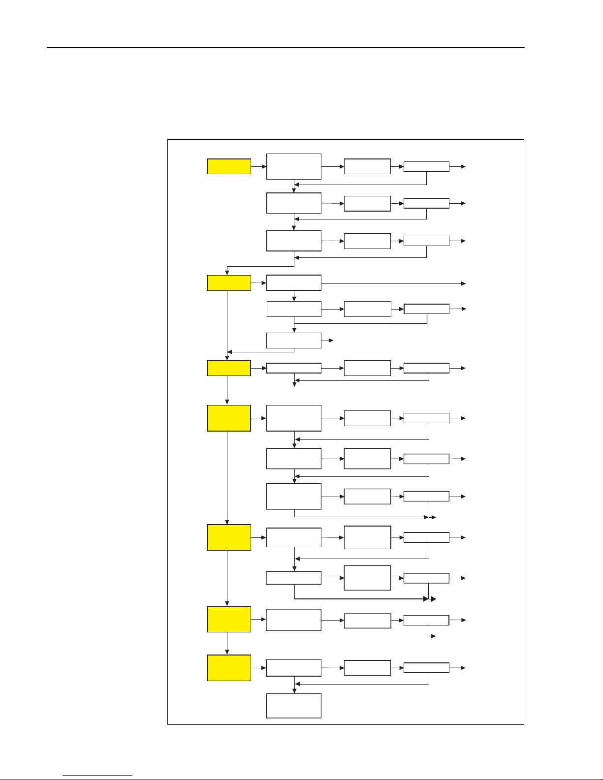
Trouble-shooting Micropilot M FMR231 with FOUNDATION Fieldbus
72 Endress+Hauser
9 Trouble-shooting
9.1 Trouble-shooting instructions
L00-FMR2xxxx-19-00-00-en-010
Instrument does
not respond
Check voltage and
compare it with the
specifications on the
nameplate.
Connect the
correct voltage
Instrument works? Ready
Check the polarity
of the voltage.
Check power connection
to electronic board
Correct the polarity
Connect plug
Instrument works?
Instrument works?
Ready
Ready
Values on display
invisible
ok
ok
ok
Yes
Yes
Yes
No
No
No
No
Not ok
Not ok
Not ok
Check plug contact
of the display.
Connect the plug
correctly
Correct configuration
Display works?
Ready
Ready
Yes
ok
No
Not ok
Yes
No
Micropilot M FMR 2xx -Trouble Shooting
ok
Output current between
3.6 …22mA ?
Contrast:
FO+
The display is possibly defective.
Contact E+H Service
Yes
Output current
< 3,6 mA ?
No
Check cabling
Correct the
cabling
Current is ok? Ready
Yes
No
Possibly defective electronics
Contact E+H Service
HART
communication
does not
function
Is the communication
resistor installed
according to the
OM?
Install the resistor
(see the OM)
Communication ok?
Ready
Ready
ok
Yes
Yes
No
No
Connect the
Commubox
(see the OM)
Communication ok?
Ready
Set the switch
correctly
Communication ok
Ready
Ready
Contact E+H Service
Contact E+H Service
Contact E+H Service
ok
ok
ok
Yes
No
Yes
Yes
No
No
ok
Not ok
Not ok
Not ok
Not ok
Not ok
Not ok
?
Is the switch on the
Commubox for
selecting HART/Intensor
in the correct position?
Is the Commubox
connected according
to the OM?
Communication
via Service adapter
does not function
Instrument
measures
incorrectly
Check configuration
of COM port on PC
Check basic setup
Proceed according
to section
'Trouble shooting’ in OM
Repeat
basic setup
Not ok
Yes
Yes
Yes
Yes
Yes
Communication
PA does not
function
Check cabling +
terminator
EMC interference?
ok
Correct cabling +
terminator
Not ok
Check screening
(see OM Section
'Connection’)
Yes
Communication ok?
Communication ok?
Measurement ok?
Ready
Yes
No
Communication ok?
Ready
Yes
No
Page 73

Micropilot M FMR231 with FOUNDATION Fieldbus Trouble-shooting
Endress+Hauser 73
9.2 System error messages
9.2.1 Current error
Errors which the Micropilot M detects during commissioning or operation are displayed:
• VU331:
error symbol in the "measured value" (000) function
• VU331 or Endress+Hauser operating program:
in the "diagnostics" (0A) function group in the "present error" (0A0) function
Only the highest priority error is displayed; in the case of multiple errors, you can scroll between
the different error messages by pressing O or S.
• FOUNDATION Fieldbus:
– by the status of the main value in the cyclic data telegram
– Diagnostic Block, parameter PARACTUALERROR (present error)
FMR2xx-FF-Diagnosticblock-in-NIConfig
9.2.2 Last error
The last error is displayed in the "diagnostics" (0A) function group in the "previous error"
(0A1) function. This display can be deleted in the "clear last error" (0A2) function.
Page 74
Trouble-shooting Micropilot M FMR231 with FOUNDATION Fieldbus
74 Endress+Hauser
9.2.3 Types of error
9.2.4 Error codes
Type of error Symbol Meaning
Alarm (A)
continuous
The output signal assumes a value which can be set using the "output
on alarm" (010) function:
• MAX: 110 %
•MIN: -10%
• Hold: last value is on hold
• User-specific value
Warning (W)
flashing
The device continues measurement. An error message is displayed.
Alarm/Warning (E) You can define whether the error should behave as an alarm or as a warning.
Code Description Possible cause Remedy
A102 checksum error
general reset & new
calibr.required
device has been powered off before data
could be stored;
emc problem;
E
2
PROM defect
reset;
avoid emc problem;
if alarm prevails after reset,
exchange electronics
W103 initialising - please wait E
2
PROM storage not yet finished wait some seconds; if warning
prevails, exchange electronics
A106 downloading please wait processing data download wait until warning disappears
A110 checksum error
general reset & new
calibr.required
device has been powered off before data
could be stored;
emc problem;
E
2
PROM defect
reset;
avoid emc problem;
if alarm prevails after reset,
exchange electronics
A111 electronics defect RAM defective reset;
if alarm prevails after reset,
exchange electronics
A113 electronics defect RAM defective reset;
if alarm prevails after reset,
exchange electronics
A114 electronics defect E
2
PROM defect reset;
if alarm prevails after reset,
exchange electronics
A115 electronics defect general hardware problem reset;
if alarm prevails after reset,
exchange electronics
A116 download error
repeat download
checksum of stored data not correct restart download of data
A121 electronics defect no factory calibration existant;
EPROM defective
contact service
W153 initialising - please wait initialisation of electronics wait some seconds; if warning
prevails, power off device and
power on again
A155 electronics defect hardware problem reset;
if alarm prevails after reset,
exchange electronics
A160 checksum error
general reset & new
calibr.required
device has been powered off before data
could be stored;
emc problem;
E
2
PROM defect
reset;
avoid emc problem;
if alarm prevails after reset,
exchange electronics
Page 75
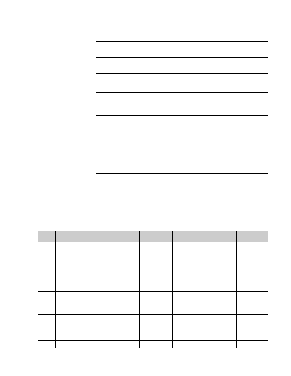
Micropilot M FMR231 with FOUNDATION Fieldbus Trouble-shooting
Endress+Hauser 75
9.2.5 Influence of the error codes on the output signal
The following table describes the influence of the error codes on the status of the cyclic output
values as well as on the parameters BLOCK_ERR and XD_ERROR in the Sensor Block.
The output values are linked to the following measuring values:
• Primary Value (PV): level/volume
• Secondary Value (SV): distance between sensor membrane and surface of the material measured
• Third Value (TV): sensor temperature
A164 electronics defect hardware problem reset;
if alarm prevails after reset,
exchange electronics
A171 electronics defect hardware problem reset;
if alarm prevails after reset,
exchange electronics
A231 sensor 1 defect
check connection
HF module or electronics defective exchange HF module or electronics
W511 no factory calibration ch1 factory calibration has been deleted record new factory calibration
A512 recording of mapping please
wait
mapping active wait some seconds until alarm
disappears
A601 linearisation ch1 curve not
monotone
linearisation not monotonously increasing correct linearisation table
W611 less than 2 linearisation
points for channel 1
number of entered linearisation points < 2 correct linearisation table
W621 simulation ch. 1 on simulation mode is active switch off simulation mode
E641 no usable echo
channel 1
check calibr.
echo lost due to application conditions or
built up on antenna
check installation;
optimize orientation of antenna;
clean antenna (cf. OM)
E651 level in safety distance - risk
of overspill
level in safety distance alarm will disappear as soon as level
leaves safety distance;
E671 linearisation ch1 not
complete, not usable
linearisation table is in edit mode activate linearisation table
Code Description Possible cause Remedy
Code PV Status
SV Status
PV Substatus
SV Substatus
TV Status TV Substatus BLOCK_ER XD_ERROR
A102 BAD Device Failure BAD Device Failure Memory Failure/
Device needs maintenance now
Electronic Failure
W103 Uncertain Non specific GOOD Non specific Other Unspecified Err
A106 BAD Device Failure BAD Device Failure Other Unspecified Err
A110 BAD Device Failure BAD Device Failure Memory Failure/
Device needs maintenance
Electronic Failure
A111 BAD Device Failure BAD Device Failure Memory Failure/
Device needs maintenance now
Electronic Failure
A113 BAD Device Failure BAD Device Failure Memory Failure/
Device needs maintenance now
Electronic Failure
A114 BAD Device Failure BAD Device Failure Memory Failure/
Device needs maintenance now
Electronic Failure
A115 BAD Device Failure BAD Device Failure Device needs maintenance now Unspecified Err
A116 BAD Device Failure BAD Device Failure Device needs maintenance now Unspecified Err
A121 BAD Device Failure BAD Device Failure Memory Failure/
Device needs maintenance now
Electronic Failure
W153 Uncertain Non specific GOOD Non specific Power up No Error
Page 76

Trouble-shooting Micropilot M FMR231 with FOUNDATION Fieldbus
76 Endress+Hauser
A155 BAD Device Failure BAD Device Failure Device needs maintenace now Electronic Failure
A160 BAD Device Failure BAD Device Failure Memory Failure/
Device needs maintenance now
Electronic Failure
A164 BAD Device Failure BAD Device Failure Memory Failure/
Device needs maintenance now
Electronic Failure
A171 BAD Device Failure BAD Device Failure Memory Failure/
Device needs maintenance now
Electronic Failure
A231 BAD Device Failure BAD Device Failure Device needs maintenance now Unspecified Err
A511 Uncertain configuration error GOOD Non specific Other Configuration Error
A512 Uncertain Non specific GOOD Non specific Other Unspecified Err
W601 Uncertain configuration error GOOD Non specific Other Configuration Error
W611 Uncertain configuration error GOOD Non specific Other Configuration Error
W621 Uncertain Non specific GOOD Non specific simulation active No Error
E641
(Alarm)
BAD Device Failure GOOD Non specific Device needs maintenance now Unspecified Err
E641
(Warning)
Uncertain Non specific GOOD Non specific Device needs maintenance now Unspecified Err
E651
(Alarm)
BAD Device Failure GOOD Non specific Other Unspecified Err
E651
(Warning)
Uncertain Non specific GOOD Non specific Other Unspecified Err
A671 BAD Device Failure GOOD Non specific Configuration Error No Error
Code PV Status
SV Status
PV Substatus
SV Substatus
TV Status TV Substatus BLOCK_ER XD_ERROR
Page 77
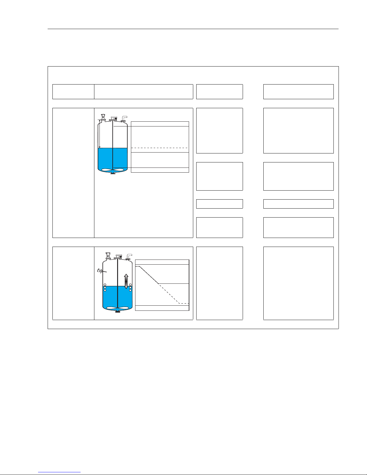
Micropilot M FMR231 with FOUNDATION Fieldbus Trouble-shooting
Endress+Hauser 77
9.3 Application errors
Error Output Possible cause Remedy
A warning or alarm
has occurred.
Depending on the configuration See table of error mes-
sages (see Page 73)
1. See table of error messages
(see Page 73)
Measured value
(00) is incorrect
L00-FMR2xxxx-19-00-00-en-019
Measured distance
(008) OK?
yes
→
1. Check empty calibr. (005) and
full calibr. (006).
2. Check linearisation:
→
level/ullage (040)
→
max. scale (046)
→
diameter vessel (047)
→
Check table
no
↓
Measurement in bypass
or stilling well?
yes
→
1. Is bypass or stilling well selected
in tank shape (002)?
2. Is the pipe diameter (007) correct?
no
↓
Is an offset (057) active? yes →1. offset (057) correctly set?
no
↓
An interference echo
may have been evaluated.
yes
→
1. Carry out tank mapping
→
basic setup
No change off
measured value on
filling/emptying
L00-FMR2xxxx-19-00-00-en-014
Interference echo from
installations, nozzle or
extension on the
antenna
1. Carry out tank mapping
→
basic setup
2. If necessary, clean antenna
3. If necessary, select better mounting position (see Page 14)
4. If necessary due to wide
interference echos set function
detection window (0A7) to "off"
100%
F m/ft
E m/ft
0% t
→
D m/ft (008)
actual
expected
100%
0% t
→
actual
expected
Page 78
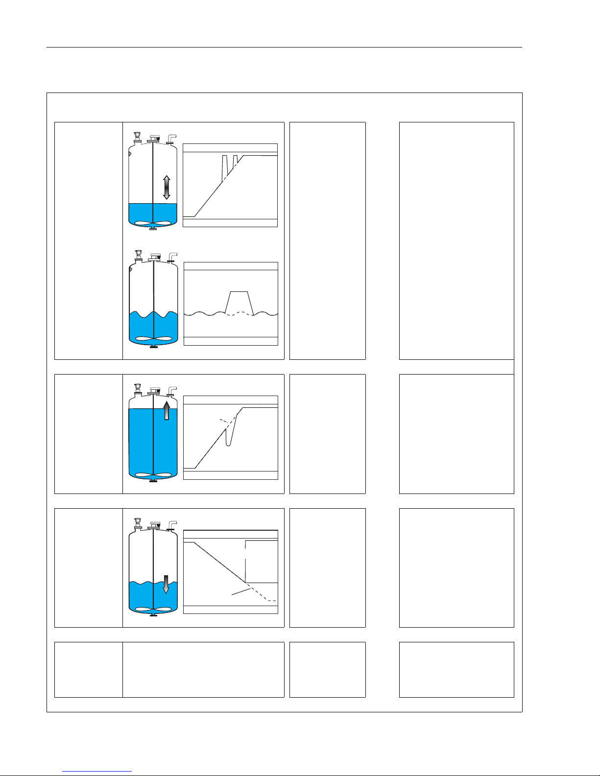
Trouble-shooting Micropilot M FMR231 with FOUNDATION Fieldbus
78 Endress+Hauser
Error Output Possible cause Remedy
If the surface is not
calm (e.g. filling,
emptying, agitator
running), the
measured value
jumps sporadically
to a higher level
L00-FMR2xxxx-19-00-00-en-015
L00-FMR2xxxx-19-00-00-en-016
Signal is weakened by
the rough surface – the
interference echoes are
sometimes stronger
1. Carry out tank mapping
→
basic
setup
2. Set the process cond. (004) to
"turb. surface" or "agitator"
3. Increase the output damping
(058)
4. Optimise the orientation
(see Page 79)
5. If necessary, select a better
mounting position and/or larger
antenna (see Page 14)
During filling/
emptying the
measured value
jumps ownwards
L00-FMR2xxxx-19-00-00-en-017
Multiple echoes yes →1. Check the tank shape (002), e.g.
"dome ceiling" or "horizontal
cyl"
2. In the range of the blocking dist.
(059) there is no echo evaluation
→
Adapt the value
3. If possible, do not select central
installation position
(see Page 14)
4. Perhaps use a stilling well ()
E 641 (loss of
echo)
L00-FMR2xxxx-19-00-00-en-018
Level echo is too weak.
Possible causes:
• Rough surface due to
filling/ emptying
• Agitator running
•Foam
yes
→
1. Check application arameters
(002), (003) and (004)
2. Optimise alignment
(see Page 79)
3. If necessary, select a better installation position and/or larger
antenna (see Page 14)
E 641 (loss of
echo) after turn on
the power supply
If the instrument is configured to Hold by loss of
echo the output is set to any value/current.
noise level during the
initialisation phase to
high.
Repeat once more empty calibr.
(005).
Caution!
Before conformation change with
O
or S to the edit mode.
100%
0% t →
actual
expected
100%
0% t →
actual
expected
100%
0% t →
actual
expected
100%
E 641
0% t →
eingetreten
erwartet
Page 79
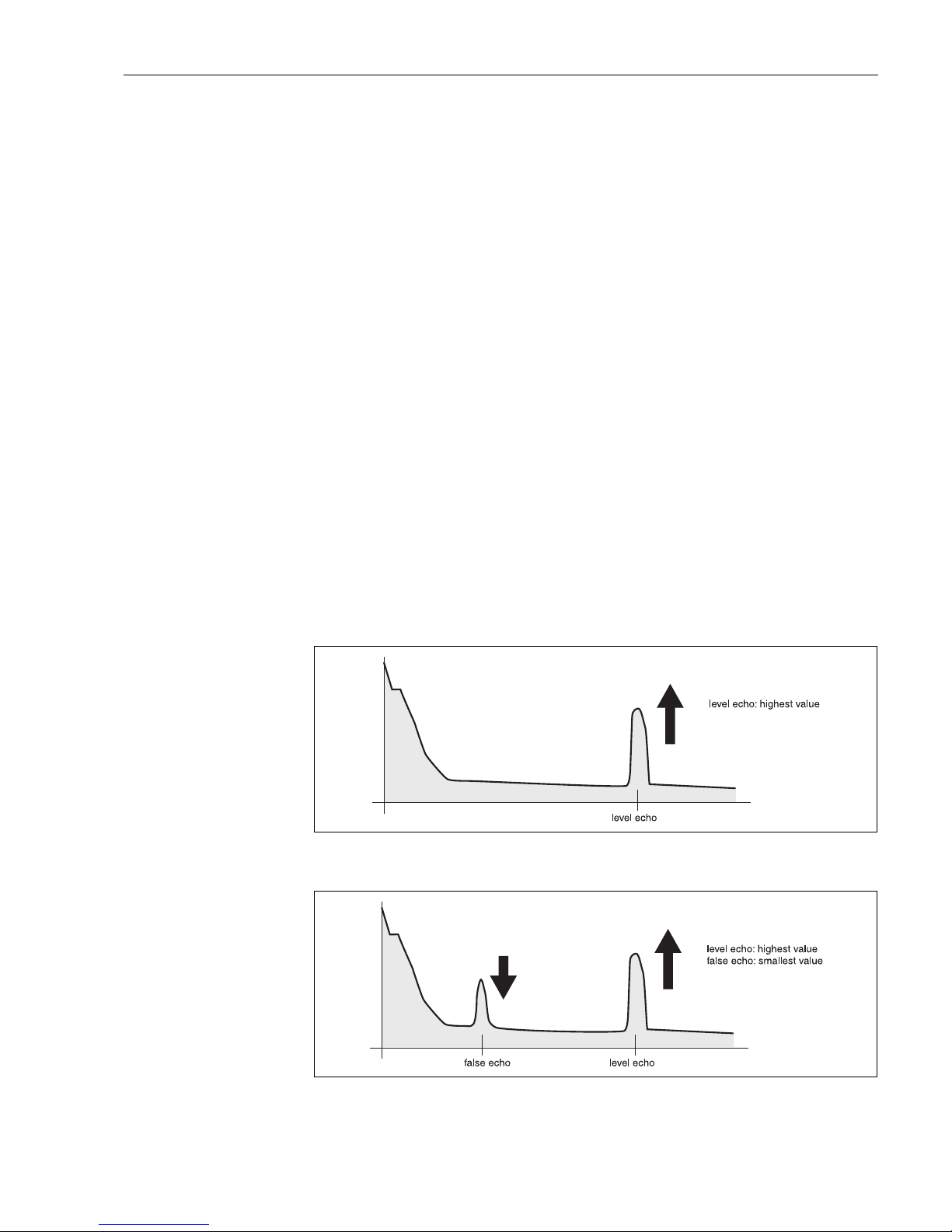
Micropilot M FMR231 with FOUNDATION Fieldbus Trouble-shooting
Endress+Hauser 79
9.4 Orientation of the Micropilot
For orientation a marker is found on the flange or threaded boss of the Micropilot. During
installation this must be oriented as follows (see Page 10):
• In tanks: to the vessel wall
• In stilling wells: to the slots
• In bypass pipes: vertical to the tank connectors
After commissioning the Micropilot, the echo quality indicates whether a sufficiently large
measuring signal is obtained. If necessary, the quality can be optimised later. Vice versa, the
presence of an interference echo can be used to minimise this by optimum orientation. The
advantage of this is that the subsequent tank mapping uses a somewhat lower level that causes an
increase in the strength of the measuring signal.
Proceed as follows:
#
Warning!
Subsequent alignment can lead to personal injury. Before you unscrew or loosen the process
connection, make sure that the vessel is not under pressure and does not contain any injurious
substances.
1. It is best to empty the container so that the bottom is just covered. However, alignment can be
carried out even if the vessel is empty.
2. Optimisation is best carried out with the aid of the envelope graph in the display or the
ToF Tool.
3. Unscrew the flange or loosen the threaded boss by a half a turn.
4. Turn the flange by one hole or screw the threaded boss by one eighth of a turn. Note the echo
quality.
5. Continue to turn until 360° is reached.
6. Optimum alignment:
L00-FMRxxxxx-19-00-00-en-002
Fig. 4: Vessel partly full, no interference echo obtained
L00-FMRxxxxx-19-00-00-en-003
Fig. 5: Vessel partly full, interference echo obtained:
Page 80
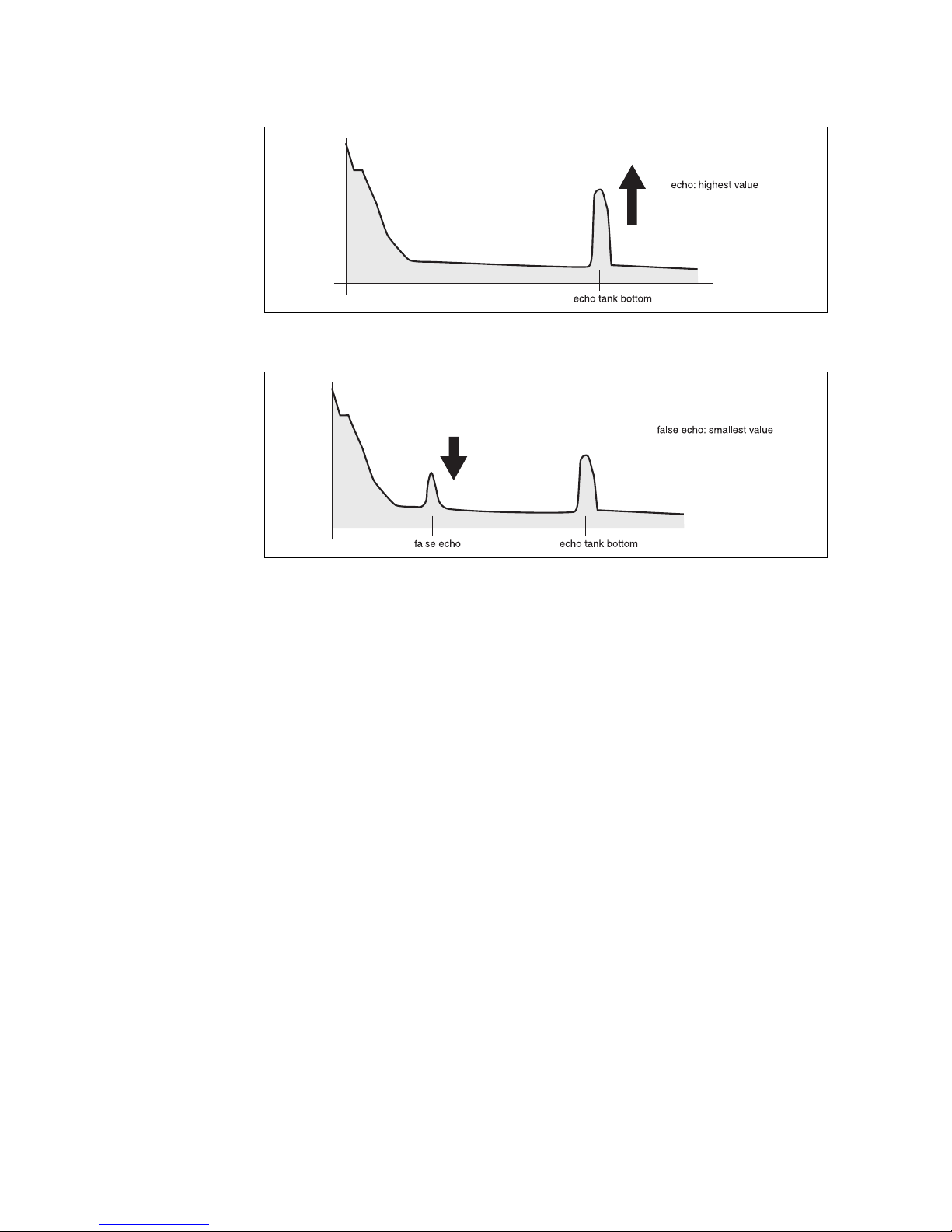
Trouble-shooting Micropilot M FMR231 with FOUNDATION Fieldbus
80 Endress+Hauser
L00-FMRxxxxx-19-00-00-en-004
Fig. 6: Vessel empty, no interference echo
L00-FMRxxxxx-19-00-00-en-005
Fig. 7: Vessel empty, interference echo obtained
7. Fix the flange or threaded boss in this position.
If necessary, replace the seal.
8. Carry out tank mapping, see Page 52.
Page 81
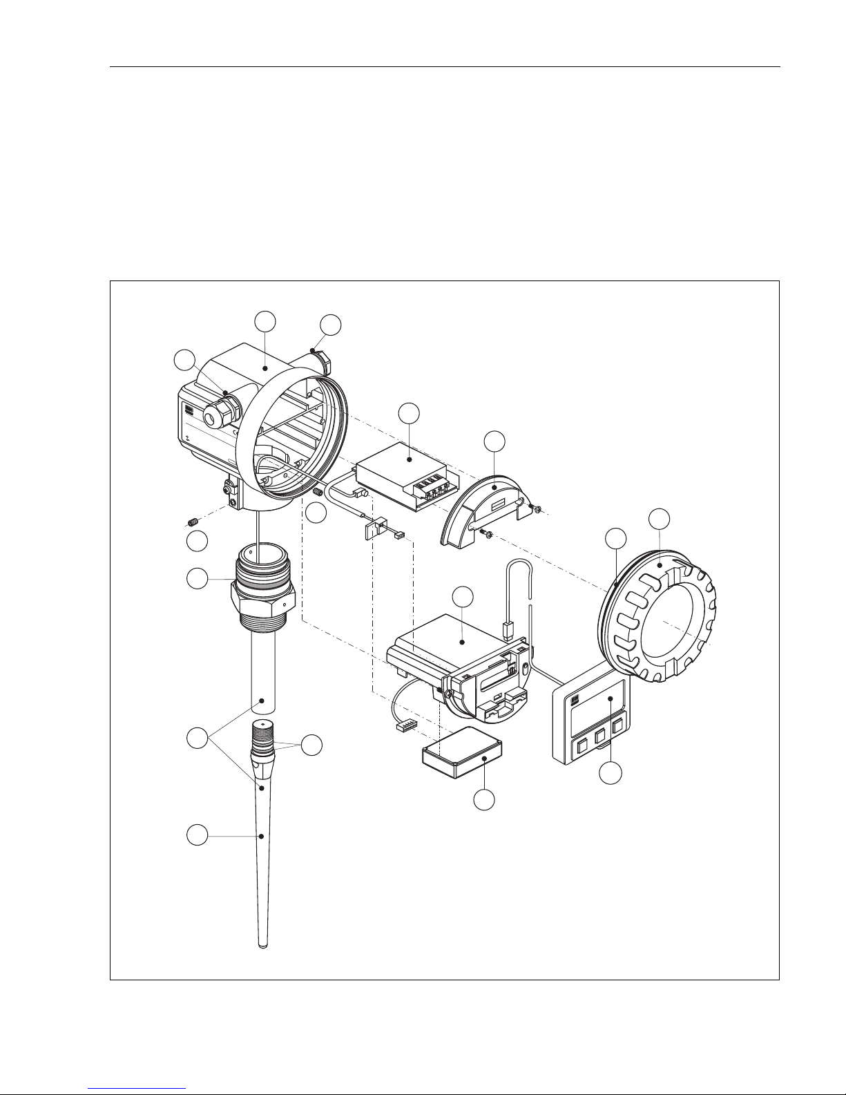
Micropilot M FMR231 with FOUNDATION Fieldbus Trouble-shooting
Endress+Hauser 81
9.5 Spare parts
!
Note!
You can order spare parts directly from your E+H service organization by giving the serial number
which is printed on the measuring transducer nameplate (see Page 6). The corresponding spare part
number also appears on each spare part. Installation instructions are given on the instruction card
that is also delivered.
Spare parts Micropilot M FMR231, F12 housing with combined wiring and electronics
compartment
L00-FMR231xx-00-00-06-xx-001
ENDRESS+HA
USER
MICROPILOT II
IP 65
Order Code:
Ser.-No.:
Messbereich
Measuring range
U 16...36V DC
4...20 mA
max.20 m
Made in Germany Maulburg
Made in Germany Maulburg
T >70°C :
A
t >85°C
1
2
3
4
Terminal
10
65
65
11
65
65
50
55
35
30
31
12
12
40
ENDRESS+HAUSER
65
20
Page 82

Trouble-shooting Micropilot M FMR231 with FOUNDATION Fieldbus
82 Endress+Hauser
10 Housing - for E+H service only!
11 Hood for terminal compartment
52006026 Cover terminal compartment F12
52019062 Hood terminal compartment F12, FHX40
12 Screw set
535720-9020 Set of screws housing F12/T12
20 Cover
52005936 Cover F12/T12 Aluminium, window, gasket
517391-0011 Cover F12/T12 Aluminium, coated, gasket
30 Electronics
71023757 Electronics FMR23x/FMR24x, Ex, HART, 4.0
71023758 Electronics FMR23x/FMR24x, Ex, PA, 4.0
71023759 Electronics FMR23x/FMR24x, Ex, FF, 4.0
31 HF module
517260-0063 HF module MICROPILOT-M, 6,3 GHz
35 Terminal module / power supply board
52006197 Terminal module 4pole, HART, 2-wire with cable connection
52012156 Terminal module 4pole, PROFIBUS PA, FOUNDATION Fieldbus
52014817 Terminal module 4pole, HART,
ferrit (F12), GL marine certificate
52014818 Terminal module 4pole, PROFIBUS PA, FOUNDATION Fieldbus
ferrit (F12), GL marine certificate
40 Display
52026443 Display VU331, version 2
50 Antenna assembly with process connection on request!
55 Rod antenna
543109-0000 Rod antenna, PPS, + Viton O-ring
65 Sealing kit
535720-9010 consists of:
2 x gasket Pg13.5 FA
2 x O-ring 17.0x2.0 EPDM
1 x O-ring 49.21x3.53 EPDM
2 x O-ring 17.12x2.62 FKM
1 x O-ring 113.9x3.63 EPDM
1 x O-ring 72.0x3.0 EPDM
Page 83
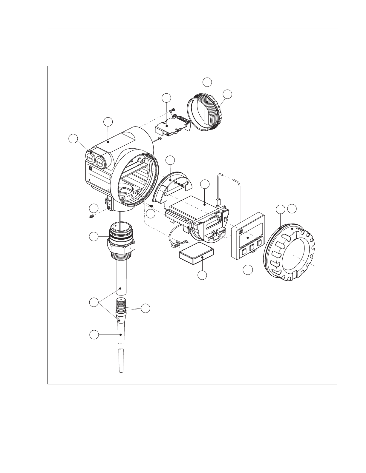
Micropilot M FMR231 with FOUNDATION Fieldbus Trouble-shooting
Endress+Hauser 83
Spare parts Micropilot M FMR231, T12 housing with separate wiring and electronics
compartment
L00-FMR231xx-00-00-06-xx-002
ENDRESS+HAUSER
MICROPILOT FMR
IP 65
Order Code:
Ser.-No.:
Messbereich
Measuring range
U 16...36V DC
4...20 m
A
max.20 m
Made in Germany Maulburg
Made in Germany Maulburg
T >70°C :
A
t >85°C
10
65
65
25
65
11
30
35
31
12
12
20
50
55
65
65
40
ENDRESS+HAUSER
Page 84

Trouble-shooting Micropilot M FMR231 with FOUNDATION Fieldbus
84 Endress+Hauser
10 Housing - for E+H service only!
11 Hood for terminal compartment
52005643 Hood T12
12 Screw set
535720-9020 Set of screws housing F12/T12
20 Cover
52005936 Cover F12/T12 Aluminium, window, gasket
517391-0011 Cover F12/T12 Aluminium, coated, gasket
25 Cover for terminal compartment
518710-0020 Cover T3/T12, Aluminium, coated, gasket
30 Electronics
71023757 Elektronik FMR23x/FMR24x, Ex, HART, 4.0
71023758 Elektronik FMR23x/FMR24x, Ex, PA, 4.0
71023759 Elektronik FMR23x/FMR24x, Ex, FF, 4.0
31 HF module
517260-0063 HF module MICROPILOT-M, 6,3 GHz
35 Terminal module / power supply board
52013302 Terminal module 4pole, 2-wire, HART, EEx d
52013303 Terminal module 2pole, 2-wire, PROFIBUS PA / FOUNDATION Fieldbus,
EEx d
52018949 Terminal module 4pole, 2-wire, HART, EEx ia, overvoltage protection
52018950 Terminal module 4pole, 2-wire, PROFIBUS PA / FOUNDATION Fieldbus,
EEx ia, overvoltage protection
40 Display
52026443 Display VU331, version 2
50 Antenna assembly with process connection on request!
55 Rod antenna
543109-0000 Rod antenna, PPS, + Viton O-ring
65 Sealing kit
535720-9010 consists of:
2 x gasket Pg13.5 FA
2 x O-ring 17.0x2.0 EPDM
1 x O-ring 49.21x3.53 EPDM
2 x O-ring 17.12x2.62 FKM
1 x O-ring 113.9x3.63 EPDM
1 x O-ring 72.0x3.0 EPDM
Page 85

Micropilot M FMR231 with FOUNDATION Fieldbus Trouble-shooting
Endress+Hauser 85
Spare parts Micropilot M FMR231, F23 housing with combined wiring and electrinics
compartment
Stainless steel housing on request!
!
Note!
Further spare parts please find on the pages of Micropilot M FMR231, F12 housing.
20 Cover
52018670 Cover F23, 316L, sight glass, gasket
52018671 DeCoverckel F23, 316L, gasket
Page 86

Trouble-shooting Micropilot M FMR231 with FOUNDATION Fieldbus
86 Endress+Hauser
9.6 Return
The following procedures must be carried out before a transmitter is sent to Endress+Hauser e.g.
for repair or calibration:
• Remove all residue which may be present. Pay special attention to the gasket grooves and crevices
where fluid may be present. This is especially important if the fluid is dangerous to health, e.g.
corrosive, poisonous, carcinogenic, radioactive, etc.
• Always enclose a duly completed "Declaration of contamination" form (a copy of the “Declaration
of contamination” is included at the end of this operating manual). Only then can Endress
+Hauser transport, examine and repair a returned device.
• Enclose special handling instructions if necessary, for example a safety data sheet as per EN 91/
155/EEC.
Additionally specify:
• An exact description of the application.
• The chemical and physical characteristics of the product.
• A short description of the error that occurred (specify error code if possible)
• Operating time of the device.
9.7 Disposal
In case of disposal please seperate the different components according to their material consistence.
9.8 Software history
9.9 Contact addresses of Endress+Hauser
Contact addresses can be found on our homepage "www.endress.com/worldwide". If you have any
questions, please do not hesitate to contact your Endress+Hauser representative.
Date Software version Changes to software Documentation
12.2000 01.01.00 Original software.
Operated via:
– ToF Tool from version 1.5
– Commuwin II (from version 2.07-3)
– HART communicator DXR275
(from OS 4.6) withRev. 1, DD 1.
BA221F/00/en/01.01
52006323
05.2002
03.2003
01.02.00
01.02.02
• Function group: envelope curve display
• Katakana (japanese)
• current turn down (HART only)
• the customer tank map can be edited
• length of antenna extension FAR10 can be
entered directly
Operated via:
– ToF Tool from version 3.1
– Commuwin II (from version 2.08-1)
– HART communicator DXR375 with
Rev. 1, DD 1.
BA221F/00/en/03.03
52006323
01.2005 01.02.04 Function "echo lost" improved
03.2006 01.04.00 • Function: detection windowg
Operated via:
– ToF Tool from version 4.2
– FieldCare from version 2.02.00
– HART-Communicator DXR375 with
Rev. 1, DD 1.
BA221F/00/en/12.05
52006322
Page 87

Micropilot M FMR231 with FOUNDATION Fieldbus Technical data
Endress+Hauser 87
10 Technical data
10.1 Additional technical data
10.1.1 Input
Measured variable The measured variable is the distance between a reference point and a reflective surface (i.e.
medium surface).
The level is calculated based on the tank height entered.
The level can be converted into other units (volume, mass) by means of a linearization.
Operating frequency • FMR231: C-band
Up to 8 Micropilot M transmitters can be installed in the same tank because the transmitter pulses
are statistically coded.
Transmitting power Average energy density in beam direction:
10.1.2 Output
Output signal FOUNDATION Fieldbus
Signal Coding Manchester Bus Powered (MBP); Manchester II
Data transmission rate 31.25 KBit/s, voltage mode
Signal on alarm • Error symbol, error code and plain text description on the on-site display
• Status byte of the digital signal input
10.1.3 Data of the FOUNDATION Fieldbus interface
Basic Data
Distance Average energy density
1 m < 4 nW/cm
2
5 m < 0,16 nW/cm
2
Device Type 100F (hex)
Device Revision 04 (hex)
DD Revision 01 (hex)
CFF Revision 01 (hex)
ITK Version 4.61
ITK-Certification Driver-No. IT035500
Link Master (LAS) cabable yes
Link Master / Basic Device
selectable
yes; Default: Basic Device
Number VCRs 24
Number of Link-Objects in VFD 24
Page 88
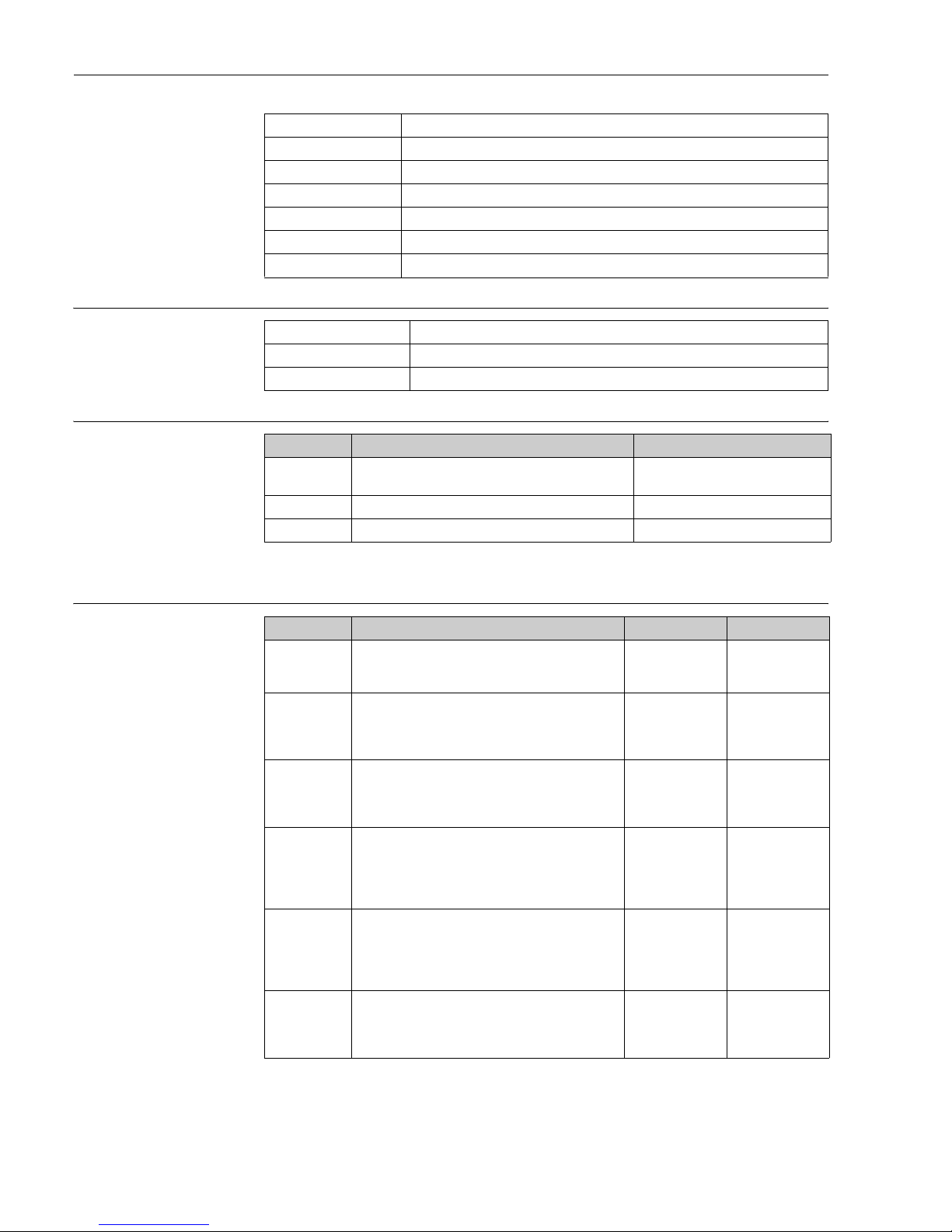
Technical data Micropilot M FMR231 with FOUNDATION Fieldbus
88 Endress+Hauser
Virtual communication
references (VCRs)
Link Settings
Transducer Blocks
Function Blocks
Permanent Entries 1
Client VCRs 0
Server VCRs 24
Source VCRs 23
Sink VCRs 0
Subscriber VCRs 23
Publisher VCRs 23
Slot time 4
Min. Inter PDU delay 4
Max. response delay 10
Block Content Output values
Sensor Block contains all parameters related to the mesurement • level or volume
1)
(channel 1)
• distance (channel 2)
1) je nach Konfiguration des Sensor-Blocks
Diagnsotic Block contains diagnostic information no output values
Display Block contains parameters to configure the local display no output values
Block Content Execution time Functionality
Resource Block The Resource Block contains all the data that uniquely
identifies the field device. It is an electronic version of a
nameplate of the device.
enhanced
Analog Input
Block 1
Analog Input
Block 2
The AI block takes the manufacturer's input data, selected by channel number, and makes it available to other
function blocks at its output.
30 ms standard
PID Block The PID block serves as proportional-integral-derivative
controller and is used almost universally to do closedloop-control in the field including cascade and feedforward.
80 ms standard
Arithmetic Block This block is designed to permit simple use of popular
measurement math functions. The user does not have to
know how to write equations. The math algorithm is
selected by name, chosen by the user for the function to
be done.
50 ms standard
Input Selector
Block
The input selector block provides selection of up to four
inputs and generates an output based on the configured
action. This block normally receives its inputs from AI
blocks. The block performs maximum, minimum, middle,
average and ‘first good’ signal selection.
30 ms standard
Signal Characterizer Block
The signal characterizer block has two sections, each
with an output that is a non-linear function of the respective input. The non-linear function is determined by a single look-up table with 21 arbitrary x-y pairs.
40 ms standard
Page 89

Micropilot M FMR231 with FOUNDATION Fieldbus Technical data
Endress+Hauser 89
10.1.4 Auxiliary energy
Terminals Cable cross-section: 0.5 to 2.5 mm (20 to 14 AWG)
Cable entry • Cable gland M20x1.5 (recommended cable diameter 6 ... 10 mm)
• Cable entry G½ or ½ NPT
• 7/8" Foundation Fieldbus plug
Supply voltage 9 V ... 32 V
There may be additional restrictions for devices with an explosion protection certificate. Refer to the
notes in the appropriate safety instructions (XA).
Lift-off voltage 9 V
Basic current 15 mA
In-rush current ≤ 15 mA
Error current 0 mA
FISCO
FNICO compliant yes
Polarity sensitive no
10.1.5 Performance characteristics
Reference operating
conditions
• temperature = +20 °C (68 °F) ±5 °C (9 °F)
• pressure = 1013 mbar abs. (14.7 psia) ±20 mbar (0.3 psi)
• relative humidity (air) = 65 % ±20%
• ideal reflector
• no major interference reflections inside the signal beam
Integrator Block The Integrator Function Block integrates a variable as a
function of the time or accumulates the counts from a
Pulse Input block. The block may be used as a totalizer
that counts up until reset or as a batch totalizer that has a
setpoint, where the integrated or accumulated value is
compared to pre-trip and trip settings, generating discrete
signals when these settings are reached.
60 ms standard
Block Content Execution time Functionality
U
i
17,5 V
I
i
500 mA; with surge arrester 273 mA
P
i
5,5 W; with surge arrester1, 2 W
C
i
5 nF
L
i
0,01 mH
Page 90

Technical data Micropilot M FMR231 with FOUNDATION Fieldbus
90 Endress+Hauser
Maximum measured error Typical statements for reference conditions, include linearity, repeatability, and hysteresis:
• FMR 231: up to10 m ±10 mm, off10 m ±0.1% of measuring range
Resolution Digital
• FMR 231: 1mm / 0.03 % of measuring range
Reaction time The reaction time depends on the parameter settings (min. 1 s). In case of fast level changes, the
instrument needs the reaction time to indicate the new value.
Influence of ambiente
temperature
The measurements are carried out in accordance with EN 61298-3:
• digital output (HART, PROFIBUS PA, Foundation Fieldbus):
– FMR 231
average T
K
: 5 mm/10 K, max. 15 mm over the entire temperature range -40 °C...+80 °C
Effect of gas phase High pressures reduce the propagation velocity of the measuring signals in the gas/vapor above the
fluid. This effect depends on the gas/vapor and is particularly large for low temperatures. This
results in a measuring error that gets bigger as the distance increases between the device zero point
(flange) and product surface. The following table illustrates this measured error for a few typical
gases/vapors (with regard to the distance; a positive value means that too large a distance is being
measured):
Note!
When the pressure is known and constant, this measured error can, for example, be compensated
by means of linearization.
Gas phase Temperature Pressure
°C °F 1 bar/14.5 psi 10 bar/145 psi 50 bar/725 psi 100 bar/1450 psi 160 bar/2320 psi
Air
Nitrogen
20 68 0.00 % 0.22 % 1.2 % 2.4 % 3.89 %
200 392 -0.01 % 0.13 % 0.74 % 1.5 % 2.42 %
400 752 -0.02 % 0.08 % 0.52 % 1.1 % 1.70 %
Hydrogen 20 68 -0.01 % 0.10 % 0.61 % 1.2 % 2.00 %
200 392 -0.02 % 0.05 % 0.37 % 0.76 % 1.23 %
400 752 -0.02 % 0.03 % 0.25 % 0.53 % 0.86 %
Gas phase Temperature Pressure
°C °F 1 bar/14.5 psi 10 bar/145 psi 50 bar/725 psi 100 bar/1450 psi 160 bar/2320 psi
Water
(saturated
steam)
100 212 0.20 % — — — —
180 356 — 2.1 % — — —
263 505.4 — — 8.6 % — —
310 590 — — — 22 % —
364 687.2 — — — — 41.8 %
Page 91

Micropilot M FMR231 with FOUNDATION Fieldbus Technical data
Endress+Hauser 91
10.1.6 Operating conditions: Environment
Ambient temperature range Ambient temperature for the transmitter: -40 °C ... +80 °C (-40 °F … +176 °F), -50 °C
(-58 °F) on request.
The functionality of the LCD display may be limited for temperatures
Ta<-20 °C and Ta>+60 °C.
A weather protection cover should be used for outdoor operation if the instrument is exposed to
direct sunlight.
Storage temperature -40 °C … +80 °C (-40 °F … +176°F), -50 °C (-58 °F) on request.
Climate class DIN EN 60068-2-38 (test Z/AD)
Vibration resistance DIN EN 60068-2-64 / IEC 68-2-64: 20…2000 Hz, 1 (m/s
2)2
/Hz
This value can be reduced for Wave Guide antennas, depending on the length. In the event of
horizontal stress, mechanical support is required or provide the Wave Guide antenna with a
protective pipe.
Cleaning of the antenna The antenna can get contaminated, depending on the application. The emission and reception of
microwaves can thus eventually be hindered. The degree of contamination leading to an error
depends on the medium and the reflectivity, mainly determined by the dielectric constant
ε
r. If the
medium tends to cause contamination and deposits, cleaning on a regular basis is recommended.
Care has to be taken not to damage the antenna in the process of a mechanical or hose-down
cleaning (eventually connection for cleaning liquid). The material compatibility has to be considered
if cleaning agents are used!
The maximum permitted temperature at the flange should not be exceeded.
Electromagnetic compatibility • Interference Emission to EN 61326, Electrical Equipment Class B
• Interference Immunity to EN 61326, Annex A (Industrial) and NAMUR Recommendation
NE 21 (EMC)
Page 92

Technical data Micropilot M FMR231 with FOUNDATION Fieldbus
92 Endress+Hauser
10.1.7 Operating conditions: Process
Dielectric constant • in a stilling well: εr ≥ 1,4
• in free space:
ε
r ≥ 1,9
10.1.8 Mechanical construction
Weight • F12/T12 housing: approx 4 kg + weight of flange
• F23 housing: approx 7.4 kg + weight of flange
10.1.9 Certificates and approvals
CE approval The measuring system meets the legal requirements of the EC-guidelines. Endress+Hauser confirms
the instrument passing the required tests by attaching the CE-mark.
RF approvals R&TTE, FCC
Overspill protection german WHG, see ZE 244F/00/de.
SIL 2, see ASD 150F/00/en "Functional Safety Manual".
Type of antenna
Process
connection
Temperature Pressure Wetted parts
FMR231 A, B PPS — -20 °C ... +120 °C
(-4 °F ... +248 °F)
-1 ... 16 bar
(... 232 psi)
316L/1.4435, Viton, PPS
C, D PTFE
(TFM1600)
PVDF threaded
connection
-40 °C ... +80 °C
(-40 °F ... +176 °F)
-1 ... 3 bar
(... 43.5 psi)
PVDF, PTFE
Metal threaded
connection
-40 °C ... +150 °C
(-40 °F ... +302 °F)
-1 ... 40 bar
(... 580 psi)
316L/1.4435, PTFE
(TFM1600)
Flange unclad
Flange clad
2
-1 ... 16 bar
(... 232 psi)
PTFE (TFM1600)
Tri-Clamp 2" -1 ... 16 bar
(... 232 psi)
316L/1.4435, PTFE
(TFM1600)
1)
1) FDA-listed material, meets USP Class VI conformity
Tri-Clamp 3" -1 ... 10 bar
(... 145 psi)
Aseptic,
Dairy
-1 ... 25 bar
(... 362 psi)
E, F PTFE antistatc
(TFM4220,
2%
conductive
additives)
Metal threaded
connection
-40 °C ... +150 °C
(-40 °F ... +302 °F)
-1 ... 40 bar
(... 580 psi)
316L/1.4435, PTFE
(TFM4220)
Flange unclad
Flange clad
2)
2) on DN150, 6" ANSI, JIS 150A the disc is made of antistatic PTFE (=black)
-1 ... 16 bar
(... 232 psi)
PTFE (TFM4220)
↑
see ordering information
Page 93

Micropilot M FMR231 with FOUNDATION Fieldbus Technical data
Endress+Hauser 93
External standards and
guidelines
EN 60529
Protection class of housing (IP-code)
EN 61010
Safety regulations for electrical devices for measurement, control, regulation and laboratory use.
EN 61326
Emissions (equipment class B), compatibility (appendix A - industrial area)
NAMUR
Standards committee for measurement and control in the chemical industry
Ex approval XA 100F
Installation Micropilot M FMR 2xx (T12 / EEx em [ia] IIC T6)
PTB 00 ATEX 2118, Equipment marking: (II 1/2 G)
XA 101F
Installation Micropilot M FMR 2xx (T12 / EEx d [ia] IIC T6)
PTB 00 ATEX 2118, Equipment marking: (II 1/2 G)
XA 102F
Installation Micropilot M FMR 2xx (F12 / EEx ia IIC T6)
PTB 00 ATEX 2118, Equipment marking: (II 1/2 G)
XA 105F
Installation Micropilot M FMR 2xx
(T12 / PTFE antenna, nnon-conductive / EExd [ia] IIC T6)
PTB 00 ATEX 2117 X, Equipment marking: (II 1/2 G)
XA 106F
Installation Micropilot M FMR 2xx
(F12 / PTFE antenna, non-conductive / EEx ia IIC T6)
PTB 00 ATEX 2117 X, Equipment marking: (II 1/2 G)
XA 204F
Installation Micropilot M FMR 2xx (F23 / EEx ia IIC T6)
PTB 00 ATEX 2118, Equipment marking: (II 1/2 G)
XA 206F
Installation Micropilot M FMR 2xx
(F23 / PTFE antenna, non-conductive / EEx ia IIC T6)
PTB 00 ATEX 2117 X, Equipment marking: (II 1/2 G)
XA 208F
Installation Micropilot M FMR 2xx (T12 with overvoltage protection / EEx ia IIC T6)
PTB 00 ATEX 2118, Equipment marking: (II 1/2 G)
XA 210F
Installation Micropilot M FMR 2xx
(T12 with overvoltage protection / PTFE antenna, non-conductive / EEx ia IIC T6)
PTB 00 ATEX 2117 X, Equipment marking: (II 1/2 G)
XA 233F
Installation Micropilot M FMR 2xx (EEx nA IIC T6)
PTB 00 ATEX 2117 X, Equipment marking: (II 3 G)
XA 277F
Installation Micropilot M FMR 2xx (EEx ia IIC T6)
PTB 00 ATEX 2117 X, Equipment marking: (II 1/2 G, II 3 D)
Page 94

Technical data Micropilot M FMR231 with FOUNDATION Fieldbus
94 Endress+Hauser
10.1.10 Supplementary Documentation
!
Note!
This supplementary documentation can be found on our product pages on www.endress.com.
Supplementary
Documentation
• Technical Information (TI345F/00/en)
• Operating Instructions "Description of instrument functions" (BA221F/00/en)
• Safety Manual "Functional Safety Manual" (SD150F/00/en).
• Certificate "German WHG" (ZE244F/00/de).
Page 95

Micropilot M FMR231 with FOUNDATION Fieldbus Technical data
Endress+Hauser 95
Page 96
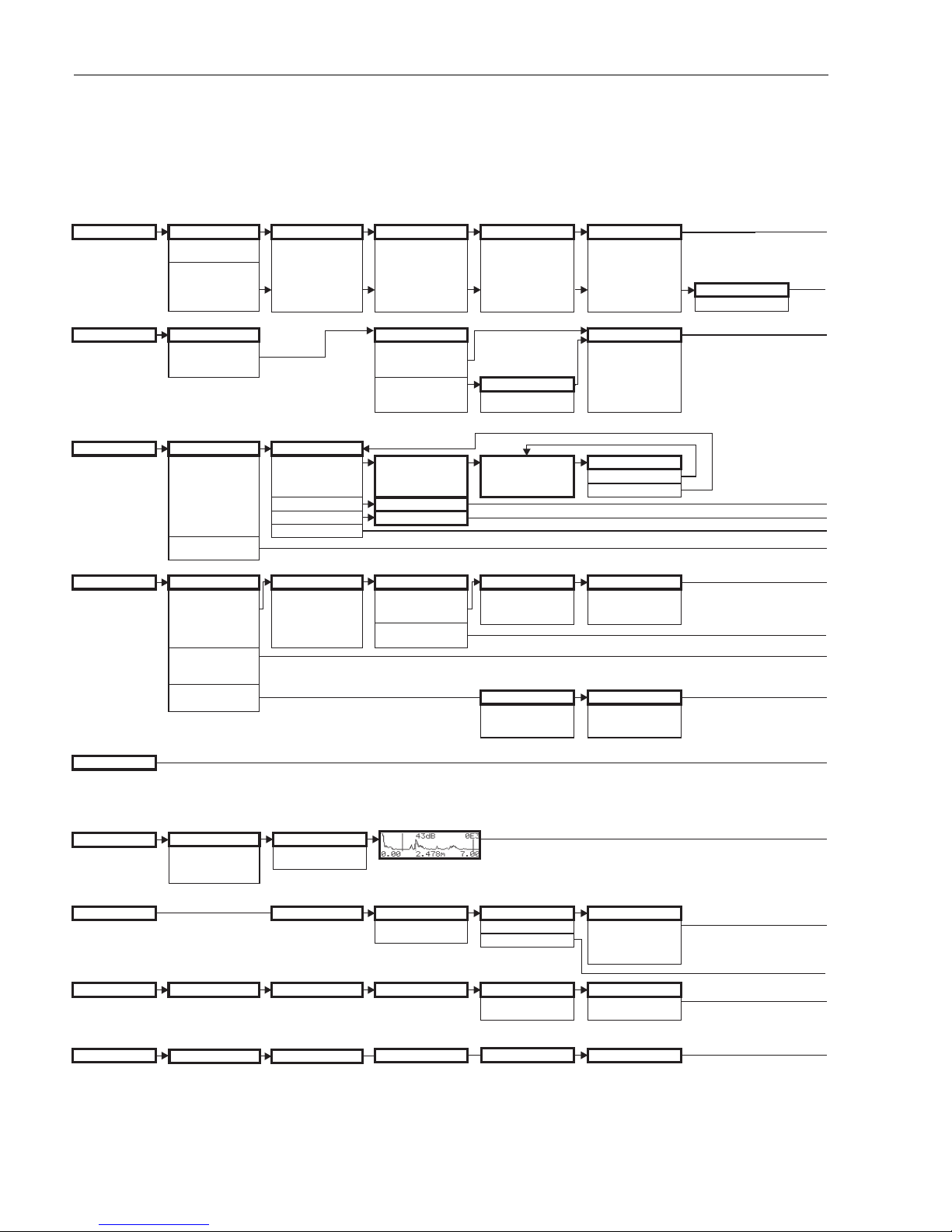
Appendix Micropilot M FMR231 with FOUNDATION Fieldbus
96 Endress+Hauser
11 Appendix
11.1 Operating menu
L00-FMR2xxxx-19-00-01-en-038
safety settings
basic setup
output on alarm
MIN -10% 3.6mA
hold
MAX 110% 22mA
tank shape
dome ceiling
horizontal cyl.
bypass
stilling well
flat ceiling
sphere
level/ullage
level DU
ullage DU
level CU
ullage CU
selection
mapping
common
extended map..
present error
enter value
medium cond.
unknown
DK: < 1.9
DK: 1.9 … 4
DK: 4 … 10
DK: > 10
linearisation
manual
semi-automatic
table on
horicontal cyl
linear
clear table
dist./meas value
D and L
are displayed
language
previous error
device id
outp. echo loss
alarm
hold
ramp %MB/min
process cond.
standard
calm surface
turb. surface
add. agitator
fast change
test: no filter
customer unit
table no.
input level
input volume
customer unit
customer unit
check distance
distance = ok
dist. too small
manual
dist. unknown
dist. too big
back to home
enter time
default: 100 s
clear last error
protocol+sw-no.
plot settings
envelope curve
env.curve+FAC
env.curve+cust.map
ramp %span/min
empty calibr.
enter value
linearisation
range of mapping
pres. Map dist
input of
mapping range
is displayed
format display
decimal
reset
for reset code
see manual
recording curve
single curve
cyclic
Note! The default values of the parameters are typed in boldface.
delay time
in case of echo loss
max. 4000 sec.
default: 30 s
full calibr.
pipe diameter
enter value
enter value
next point
yes
no
start mapping
cust. Tank map
off
on
inactive
active
reset
no. of decimals
x
x.x
x.xx
x.xxx
unlock parameter
for reset code
see manual
dd rev.
linearisation
extended calibr.
output
envelope curve
display
diagnostics
system parameter
01
00
010
002
040
040
040
050
0A0
003
041
041
008
092
0A1
0C1
012
004
042
043
044
045
042
042
051
093
0A2
0C2
0E1
013
005
052
054
094
0A3
0E2
014
006
045
053
055
095
0A4
0C4
04
05
06
0E
09
0A
0C
007
1/16”
device tag
dev. rev.
0C0
0C3
Page 97
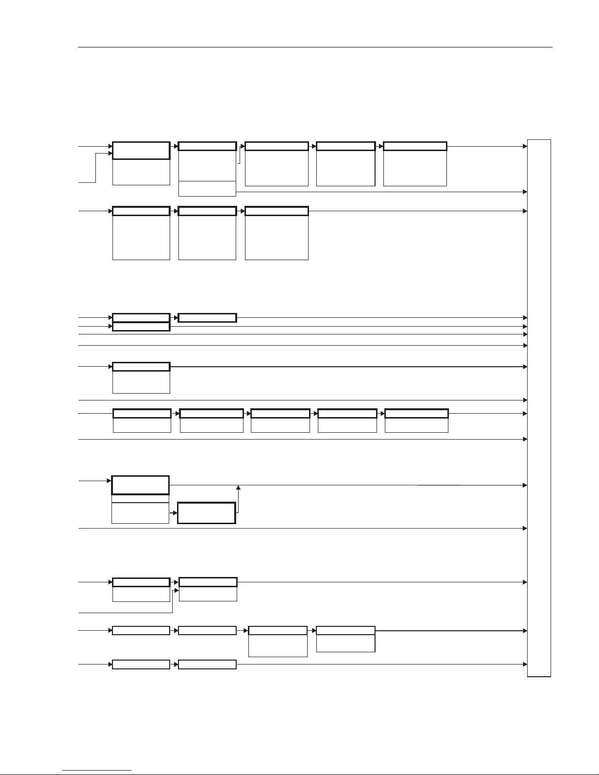
Micropilot M FMR231 with FOUNDATION Fieldbus Appendix
Endress+Hauser 97
L00-FMR2xxxx-19-00-02-en-038
dist./meas.value
D and L
are displayed
simulation
sim. off
sim. level
sim. volume
sep. character
. point
, comma
measured dist.
distance unit
max. scale
max. scale
safety distance
from blocking
distance
default: 0.1m
dist./meas.value
D and L
are displayed
echo quality
is displayed
simulation value
display test
off
on
measured level
download mode
diameter vessel
in safety dist.
alarm
self holding
warning
check distance
distance = ok
dist. too small
manual
dist. unknown
dist. too big
offset
will be added to the
measured level
ackn. alarm
no
yes
range of mapping
input of
mapping range
output dampingAntenna extens.
enter value
default: 5 s
length FAR10 for FMR230 only
application par.
Return to Group Selection
not modified
modified
start mapping
off
on
blocking dist.
is displayed
dist./meas.value
D and L
are displayed
008
065
096
0A5
0C5
046
046
015
008
056
066
097
0A6
0C8
047
016
051
057
017
052
058058
0A8
053
059
008
detection window
off
on
reset
0A7
Page 98
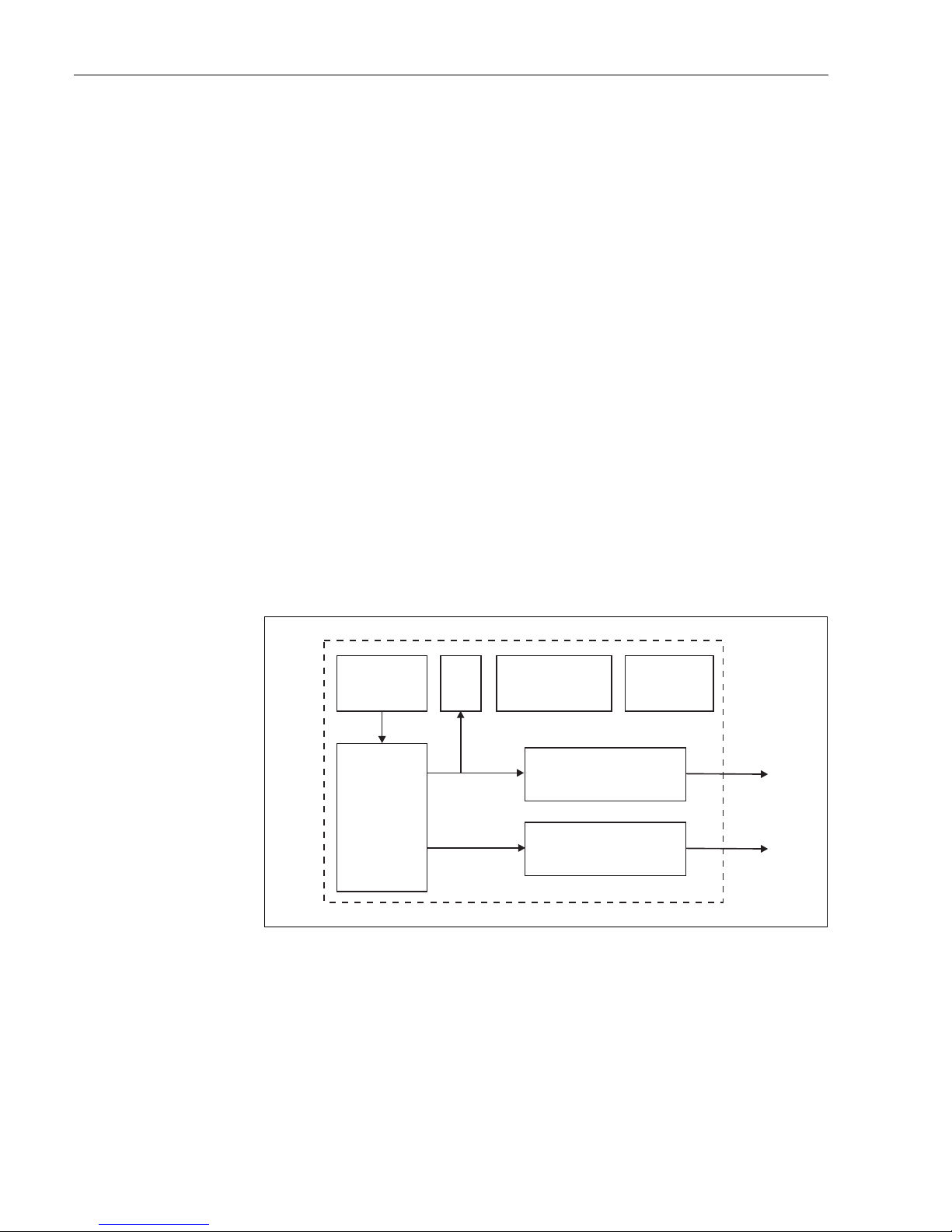
Appendix Micropilot M FMR231 with FOUNDATION Fieldbus
98 Endress+Hauser
11.2 Block model of the Micropilot M
The Micropilot M contains the follwoing blocks:
• Resource Block (RB2)
s. Operating Instructions BA013S: "FOUNDATION Fieldbus - Overview"
• Sensor Block (TBRL)
contains the parameters relevant to the measurement
• Diagnostic Block (DIAG)
contains the diagnostic parameters of the Micropilot M
• Display Block (DISP)
contains the configuration parameters for the display module VU331
• Analog-Input-Block 1 bzw. 2 (AI)
scale the signal of the Transducer Block and transmit them to the PLCS
• PID Block (PID)
s. Operating Instructions BA013S: "FOUNDATION Fieldbus - Overview"
• Arithmetic Block (AR)
s. Operating Instructions BA013S: "FOUNDATION Fieldbus - Overview"
• Input Selector Block (IS)
s. Operating Instructions BA013S: "FOUNDATION Fieldbus - Overview"
• Signal Characterizer Block (SC)
s. Operating Instructions BA013S: "FOUNDATION Fieldbus - Overview"
• Integrator Block (IT)
s. Operating Instructions BA013S: "FOUNDATION Fieldbus - Overview"
11.2.1 Default Block configuration
The input and output variables of the blocks can be interconnected by a configuration tool (e.g. NIFieldbus configurator). The figure below shows, how these connections are set by default.
L00-FMxxxxxx-02-00-00-en-002
OUT
OUT
Physical Block
parameters of the
physical unit, e.g.
tag No.
Display
Sensor
signal evaluation
Sensor Block
Parameters that
describe the
device (calibration,
linearisation etc.)
Analog Input Function Block 1
parameters that are important to
the process control system,
e.g. scaling, status
Analog Input Function Block 2
parameters that are important to
the process control system,
e.g. scaling, status
PID Block
Automation
functions
Primary value
(main value)
Secondary value
(distance)
Page 99

Micropilot M FMR231 with FOUNDATION Fieldbus Appendix
Endress+Hauser 99
11.3 Resource block
The resource block contains the parameters used to describe physical resources of the device. It has
no linkable inputs or outputs.
11.3.1 Operation
The resource block is opened by a click on the resource line.
If the NI-FBUS Configurator is being used, a series of file tabs appears on the screen. The files can
be opened to view and/or edit the parameters in the following table. A short description of the
parameter function appears on the side of the screen. A change in the parameter is stored by pressing
the WRITE CHANGES button when the block is out of service. Press the READ ALL button to check
the values stored in the device.
11.3.2 Parameters
The function of the resource block parameters not described here can can be taken from the
FOUNDATION Fieldbus specification, see "www.fieldbus.org".
Parameter Description
TAG_DESC User description of the intended application of the block.
MODE_BLK Lists the actual, target, permitted and normal operating modes of the block.
– Target: changes the operating mode of the block
– Actual: indicates the current operating mode of the block
– Permitted: states which operating modes are allowed
– Normal: indicates the normal operating mode of the block
The possible operating modes of the resources block are:
– AUTO: the block is operating as normal
– OOS: the block is out of service.
If the resource block is out of service, then all blocks within the device (resource) are
forced into the same status.
RS_STATE Indicates the state of the resource block application state machine
– On-line: block in AUTO mode
– Standby: block in OOS mode
WRITE_LOCK Indicates the status of DIP-switch WP
– LOCKED: device data can be modified
– NOT LOCKED: device data can be modified
RESTART Allows a manual restart:
– UNINITIALISED: no status
– RUN: normal operational status
– RESOURCE: resets the resource block parameters
– DEFAULTS: Resets all FOUNDATION Fieldbus parameters within the
device, but not the manufacturer specific parameters.
– PROCESSOR: make a warm start of the processor
BLOCK_ERROR Shows error status of software and hardware components
– Out-of-Service: the block is in OOS mode
– Simulation active: shows the setting of DIP-switch SIM
BLOCK_ALM Shows any configuration, hardware, connection and system problems in the lock. The
cause of the alert is to be seen in the subcode field.
Page 100
Appendix Micropilot M FMR231 with FOUNDATION Fieldbus
100 Endress+Hauser
11.4 Sensor block
The Sensor block contains the parameters required to calibrate the device. These parameters can
also be addressed by using the VU331 display module. The calibration of the device is described in
Chapter 6.
11.4.1 Operation
Parameter changes from the tool are made off-line while the device is operating. The changes are
downloaded by first setting MODE_BLK = OOS then pressing the WRITE CHANGES button. Press
the READ ALL button to check the values stored in the device. Normally operation is resumed as
soon as MODE-BLK is set to AUTO.
11.4.2 Block administration parameters
11.4.3 Output values
11.4.4 Configuration parameters
The Sensor block also contains the configuration parameters, which are used to commission and
calibrate the instrument. They are identical to the functions of the operating menu, except for the
service parameters which are not accessible on the bus. Thus, the calibration procedure via the
display module (Chapter 6.4) is equally valid for a calibration via a network configuration tool.
A complete list of the configuration parameters can be found in the "Description of Instrument
Functions", BA221F/00/en.
Parameter Description
MODE_BLK See description in Resource block. The possible operating modes of the Sensor block are:
– AUTO: the block is operating as normal
– OOS: the block is out of service.
TAG_DESC User description of the intended application of the block.
BLOCK_ERROR Shows error status of software and hardware components
– Out-of-Service: the block is in OOS mode
Parameter Description
PRIMARY_VALUE Main value (level or volume).
SECONDARY_VALUE Measured distance.
 Loading...