

Page 1
Technical Information
Memograph M
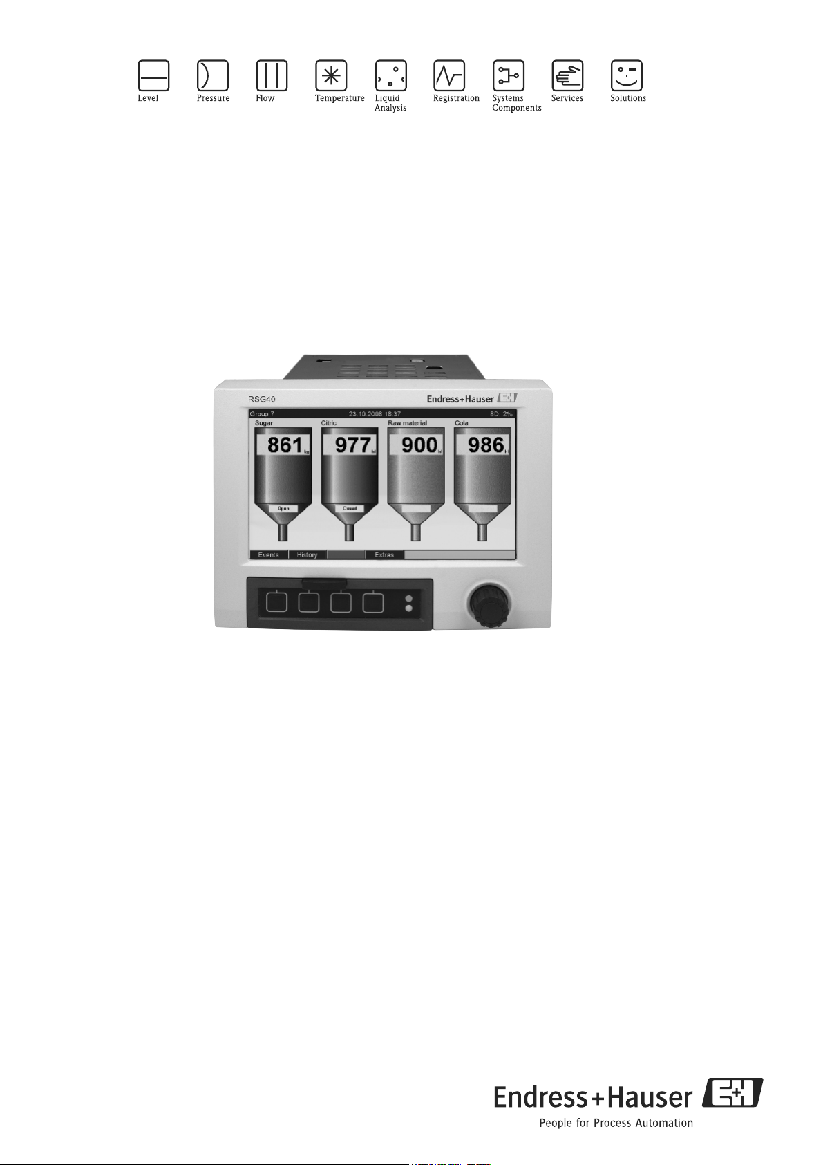
Graphic Data Manager RSG40
Record, visualize, analyze and communicate
Application
The graphic data manager Memograph M provides
information on all the relevant process variables.
Measured values are recorded correctly, limit values are
monitored and measuring points analyzed. The data are
stored in the 256 MB internal memory and also on an SD
card or USB stick. Memograph M boasts a modular
design, intuitive operation and a comprehensive security
concept. The ReadWin
standard package and is used for configuring, visualizing
and archiving the data captured. The solution for all your
tasks. For example, for:
• Process measuring technology
• Power stations and energy supply
• Steam boiler monitoring/efficiency calculation
• Food and pharmaceutical industry
• Plant and apparatus engineering and construction;
Milk pasteurization plants
• Environmental and climate measuring technology;
Storm overflow control
• Quality assurance and production
• Batch analysis; Tele-Alarm functions
• Testing bays and laboratory applications
®
2000 PC software is part of the
Your benefits
• Visual: 7" TFT display as onsite display for optimum
readability
• Fast: 100 msec scan rate for all channels, high-speed
memory cycle 100 msec for up to 8 channels
• Secure: Security package with person-specific access
authorization and electronic signature (FDA 21 CFR
11)
• Modular: Easy retrofitting to up to 20 universal inputs
and 14 digital inputs or 12 relays
• Flexible: Free choice of display mode. E.g.
instrument, process screen and circular chart display
• Limitless: Integrated Web server, fieldbus (Profibus,
Modbus), common standard protocols and interfaces
such as USB, TCP/IP, OPC and Ethernet are
supported
• Informative: Event search, automatic signal analysis
• Practicable: Installation depth 158 mm, plastic front
IP65, NEMA4; Operating via external USB keyboard,
printout via USB printer
• Clear: Alarm management with all active, confirmed
and historical alarms
TI133R/09/en
No. 71035347
Page 2
Memograph M
PSTN-/GSM-Modem
•
0/4..20mA
ReadWin®2000
M
Ethernet
V
*.csv
*.dat
100...230 V AC (±10%)
24 V (-10%; +15%) AC/DC
TFT 7”
Display
mA
USB
256 MB
Internal
memory
Serial connection
RS232, RS485
PC software
6 to 14 digital inputs
-Event
-Time
-Counter
-Control function
:
2 analog outputs option
-Frequency output
():
-Current output or
Web-Server function
OPC-Server option()
Relays:
- 1 change-over contact
- 5 to 11 normally
open contacts
0 to 20 analog inputs:
-TC
- RTD
-mA
- mV, V
- Frequency
- Pulse
Option:
- 8 mathematic channels
Mathematic functions over
formula editor freely editable
24 V, 300 mA
Transmitter power supply
output
Power
Inputs
Outputs
Memory
Communication
Fieldbus up to 40
channels (option):
-Profibus DP Slave
-Modbus RTU
-Modbus TCP/IP
Slots for external
SD-card and USB-stick
100 limit values
(variable channel mapping)
Function and system design
Measuring principle Electronic acquisition, display, recording, analysis, remote transmission and archiving of analog and digital
input signals.
Measuring system Multichannel data recording system with multicolored TFT display (170 mm/7" screen size), galvanically
isolated universal inputs (U, I, TC, RTD, pulse, frequency), digital input, transmitter power supply, limit relay,
Block circuit diagram
!
communication interfaces (USB, Ethernet, RS232/485), internal SD memory, external SD card and USB stick.
100 ms scan rate for all channels. ReadWin
data evaluation.
Note!
The number of inputs, outputs and relays contained in the basic device can be individually extended using a
maximum of five plug-in cards. The Memograph M provides power directly to connected two-wire
transmitters. The device is configured and operated via 4 keys and the navigator (jog/shuttle dial) by means of
the interface and ReadWin
®
2000 PC software or an external keyboard. The online help makes onsite
operation easier. Measured values, events and alarms are coded in accordance with the serial protocol and then
transmitted.
®
2000 PC software for comprehensive device configuration and
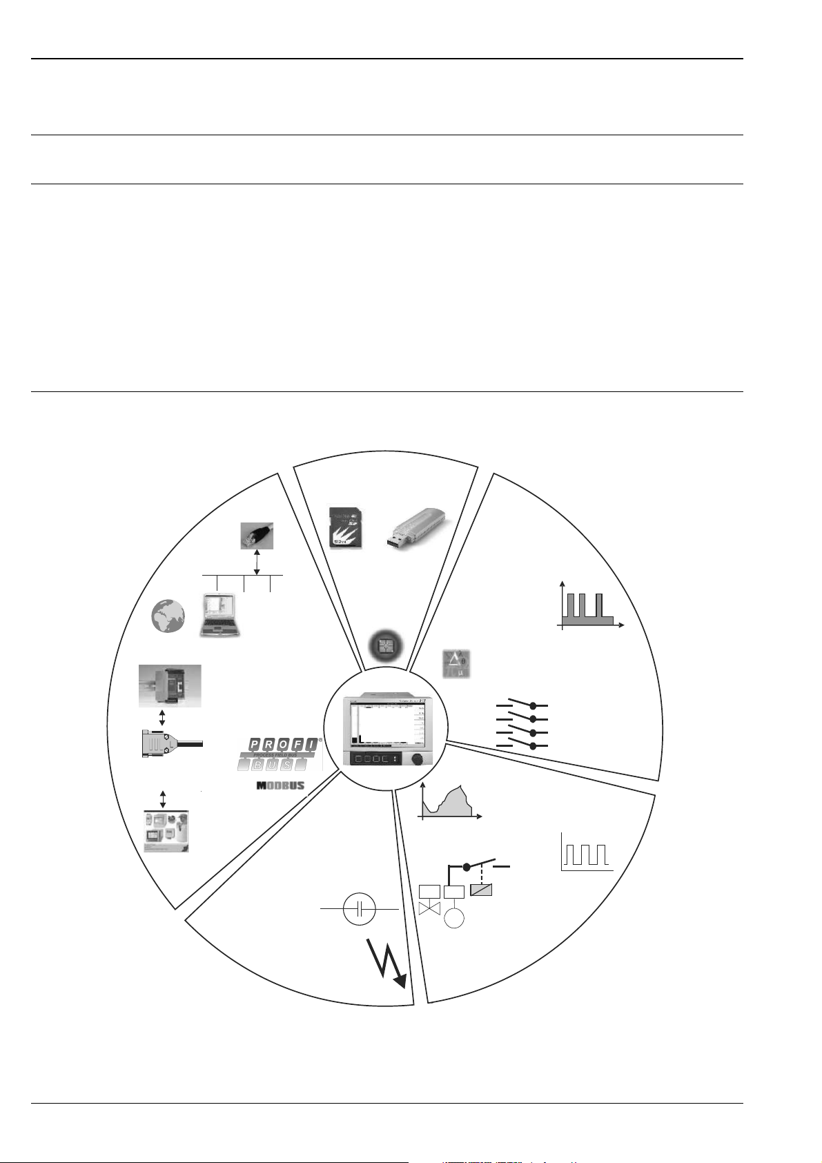
This block circuit diagram provides a rough overview of the functions.
2 Endress+Hauser
Page 3
Memograph M
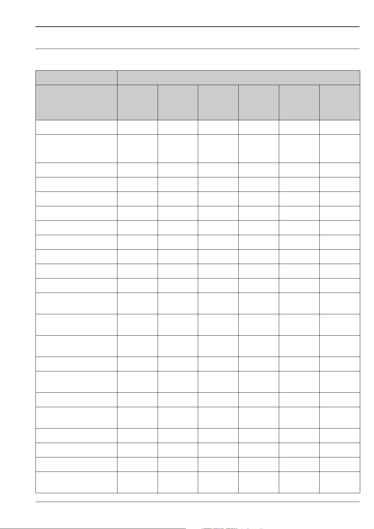
Application packages/ software options
Functions Standard incl.
Process-related graphic ГГГГГГ
Signal analysis: day, week,
month, year, external (digital
input)
Event messages/Audit Trail ГГГГГГ
Operation time counter ГГГГГГ
Text entry/comments ГГГГГГ
Change language ГГГГГГ
Time synchronization ГГГГГГ
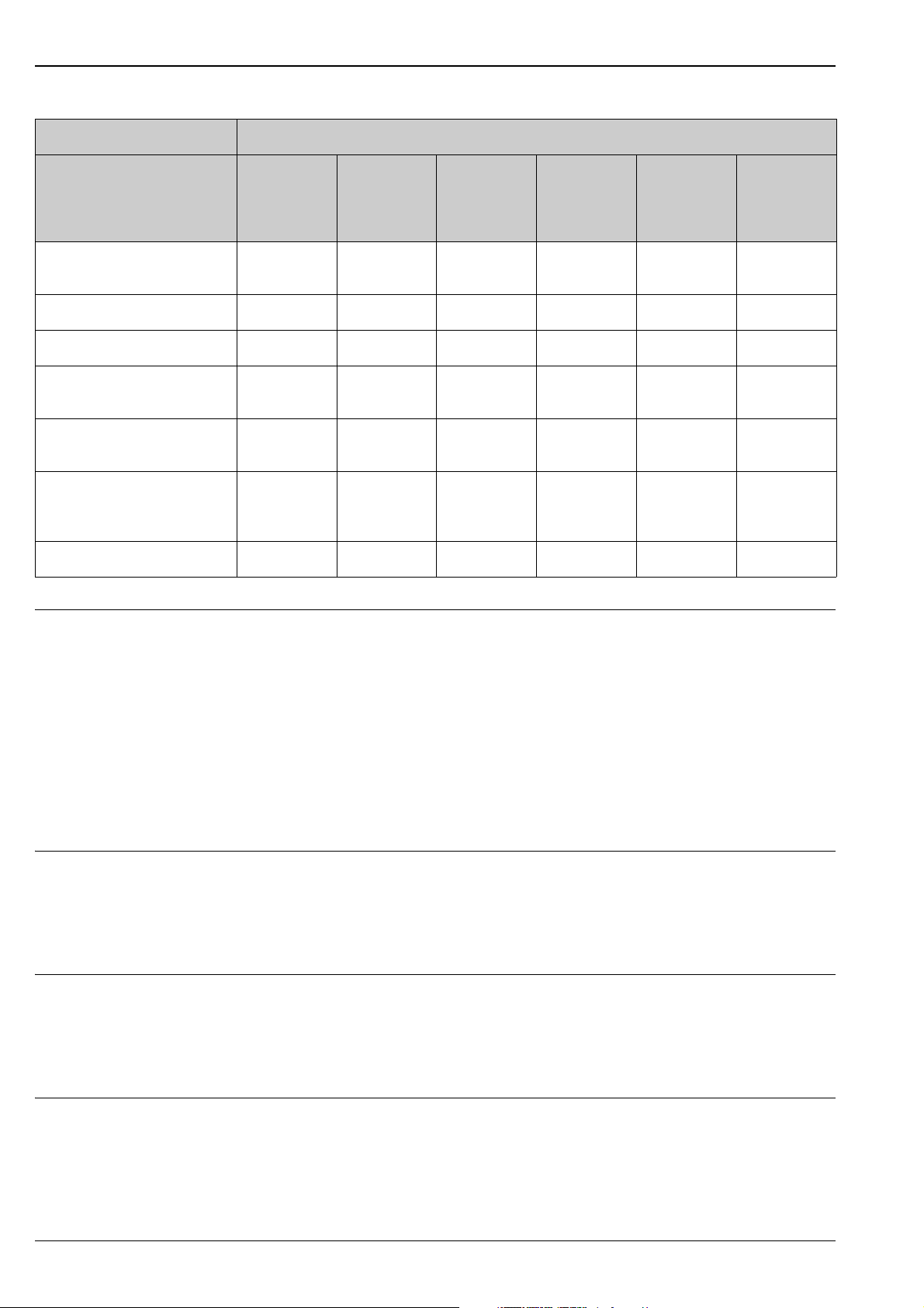
User-friendly function extension (even subsequently) through the online activation of all the optional
instrument functions. The following software options are available:
Software package
Mathematics
security
package
ГГГГГГ
package
Batch Tele Alarm Waste water +
Storm
overflow +
Tele Alarm
Energy
software,
water + steam
Web server ГГГГГГ
Linearization ГГГГГГ
External USB keyboard ГГГГГГ
External USB printer ГГГГГГ
User administration
21 CFR Part 11
Access protection through
release code
Mathematics functions via
formula editor
Logic operations ГГГГГ
Mass, heat quantity, water,
steam
Efficiency calculation Ã
Parallel batch record for 4
batches
ГГГГГГ
ГГГГГГ
ГГГГГ
Ã
Ã
USB bar code scanner Ã
Automatic batch printout Ã
Preset counter Ã
SMS/Email communication at
the event of an alarm
ÃÃ
Endress+Hauser 3
Page 4
Software package
Memograph M
Functions Standard incl.
security
package
Mathematics
package
Batch Tele Alarm Waste water +
Storm
overflow +
Tele Alarm
Querying values by cellular
ÃÃ
phone/SMS
Remote controlled relays ÃÃ
Alarm confirming via SMS ÃÃ
Storm overflow control (rain
Ã
spillway basins)
Floating highest and lowest
Ã
values for quantities
Floating highest and lowest
Ã
values of x-minute average
values
Infiltration water analysis Ã
Energy
software,
water + steam
Energy software package The Memograph M energy package provides users with the possibility of calculating the mass and energy flow
in water and steam applications on the basis of the following input variables:
• Flow
• Pressure
• Temperature (or temperature differential)
Furthermore, energy calculations are also possible using glycol-based refrigerant media.
By balancing the results against one another or by linking the results to other input variables (e.g. gas flow,
electr. energy), users can perform overall balances, calculate efficiency levels etc. These values are important
indicators for the quality of the process and form the basis for process optimization efforts, maintenance, etc.
The internationally recognized IAPWS-IF 97 standard is used to calculate the thermodynamic state variables
of water and steam.
Tele-alarm software package With the tele-alarm software it is possibly to react even when on the road. E-mails or SMS messages triggered
by process alarms or other important process events can be transmitted simultaneously to several recipients or
can be automatically forwarded. Reports can be confirmed, relays remotely switched and instantaneous
measurements retrieved via mobile telephones. Memograph M with GSM (GPRS) or Ethernet connection is
the perfect solution in the environmental industry for applications supervising unmanned outstations but also
ideally suitable for tank level supervision.
Batch software package The new Batch software allows for secure recording and visualization of discontinuous processes. Freely
definable or externally controlled evaluation cycles are simultaneously possible for up to four batches. Batches
are provided with batch specific information and the measurement readings, the beginning, the end and the
duration of every batch are displayed on the device and in the ReadWin
status. A batch printout at the end of each batch can be done directly at the device (USB printer) or can be
printed out using a PC with ReadWin
®
2000.
®
2000 software with the current batch
Water/waste water software package
A Memograph M with the water/waste water software supports in the operational supervision of the water/
waste water channel systems by recording information regarding the quality and economics of the treatment
plant. For each supply channel the daily, weekly, monthly, yearly highest and lowest values are recorded.
Seepage water recording as well as the supervision of storm overflow tanks for overflow events are also a part
of this software application package.
4 Endress+Hauser
Page 5
Memograph M
Input
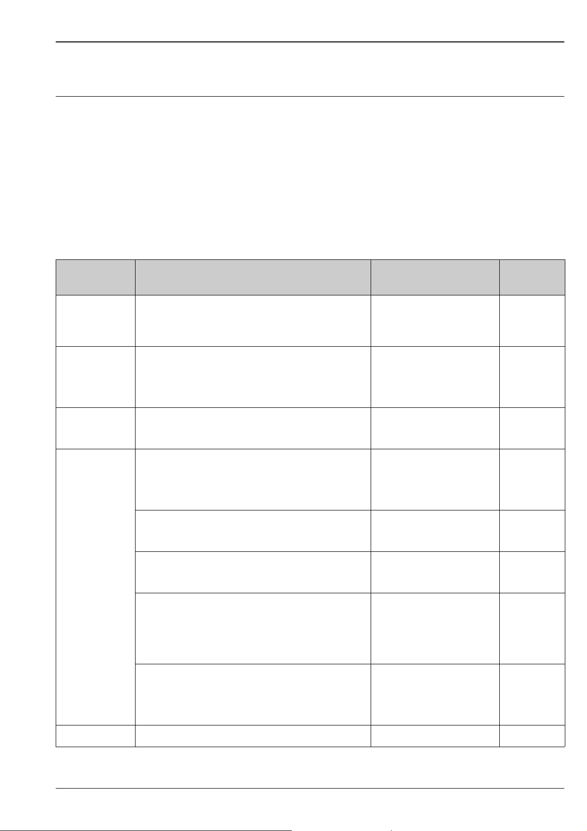
Analog multifunction inputs Number
Standard version without universal inputs.
Optional multifunction input cards (slot 1-5) each with 4 universal inputs (4/8/12/16/20).
Function
You can choose between the measured variables U, I, RTD, TC, pulse input or frequency input for each
universal input.
Measured variable, measuring range
To IEC 60873-1:
An additional display error of -/+ 1 digit is permitted for every measured value.
Measuring ranges which can be selected per channel:
Measured
variable
Current (I) 0 to 20 mA
0 to 5 mA
4 to 20 mA
Overrange: up to 22 mA
Voltage (U) > 1 V 0 to 10 V
Voltage (U) 1 V 0 to 1 V
Resistance
thermometer
(RTD)
0 to 5 V
1 to 5 V
± 10 V
± 30 V
± 1 V
± 150 mV
Pt100: -200 to 850 °C (-328 to 1562 °F) (IEC751, GOST)
Pt100: -200 to 649 °C (-328 to 1200.2 °F) (JIS1604)
Pt500: -200 to 850 °C (-328 to 1562 °F) (IEC751)
Pt500: -200 to 649 °C (-328 to 1200 °F) (JIS1604)
Pt1000: -200 to 600 °C (-328 to 1112 °F) (IEC751, JIS1604)
Cu100: -200 to 200 °C (-328 to 392 °F) (GOST)
Cu50: -200 to 200 °C (-328 to 392 °F) (GOST)
Pt50: -200 to 850 °C (-328 to 1562 °F) (GOST)
Measuring range Maximum measured error
of measuring range (oMR)
± 0.10 % oMR Load: 50 Ohm
± 0.10 % oMR 1 MOhm
± 0.10 % oMR 2.5 MOhm
4-wire: ± 0.10 % oMR
3-wire: ± (0.10 % oMR + 0.8 K)
2-wire: ± (0.10 % oMR + 1.5 K)
4-wire: ± 0.20 % oMR
3-wire: ± (0.20 % oMR + 0.8 K)
2-wire: ± (0.20 % oMR + 1.5 K)
Input
resistance
Cu53: -50 to 180 °C (-58 to 356 °F) (GOST)
Pt46: -200 to 650 °C (-328 to 1202 °F) (GOST)
Thermocouples
(TC)
Pulse input (I) Min. pulse length 30 μs, max. 13 kHz
Type J (Fe-CuNi): -210 to 1200 °C (-346 to 2192 °F) (IEC581-1)
Type K (NiCr-Ni): -270 to 1372 °C (-454 to 2501.6 °F) (IEC581-1)
Type T (Cu-CuNi): -270 to 400 °C (-454 to 752 °F) (IEC581-1)
Type N (NiCrSi-NiSi): -270 to 1300 °C (-454 to 2372 °F) (IEC581-1)
Type L (Fe-CuNi): -200 to 900 °C (-328 to 1652 °F) (DIN43710)
Type L (Fe-CuNi): -200 to 659 °C (-328 to 1218.2 °F) (GOST)
Type D (W3Re-W25Re): 0 to 2315 °C (32 to 4199 °F) (ASTME998)
Type C (W5Re-W26Re): 0 to 2315 °C (32 to 4199 °F) (ASTME998)
Type B (Pt30Rh-Pt6Rh): 0 to 1820 °C (32 to 3308 °F) (IEC581-1)
Type S (Pt10Rh-Pt): -50 to 1768 °C (-58 to 3214.4 °F) (IEC581-1)
Type R (Pt13Rh-Pt): -50 to 1768 °C (-58 to 3214.4 °F) (IEC581-1)
4-wire: ± 0.30 % oMR
3-wire: ± (0.30 % oMR + 0.8 K)
2-wire: ± (0.30 % oMR + 1.5 K)
± 0.10 % oMR as of -100 °C (-148 °F)
± 0.10 % oMR as of -130 °C (-202 °F)
± 0.10 % oMR as of -200 °C (-328 °F)
± 0.10 % oMR as of -100 °C (-148 °F)
± 0.10 % oMR as of -100 °C (-148 °F)
± 0.10 % oMR as of -100 °C (-148 °F)
± 0.15 % oMR as of 500 °C (932 °F)
± 0.15 % oMR as of 500 °C (932 °F)
± 0.15 % oMR as of 600 °C (1112 °F)
± 0.15% oMR as of 100 °C (212 °F)
± 0.15% oMR as of 100 °C (212 °F)
1 MOhm
1 MOhm
Endress+Hauser 5
Page 6
Memograph M
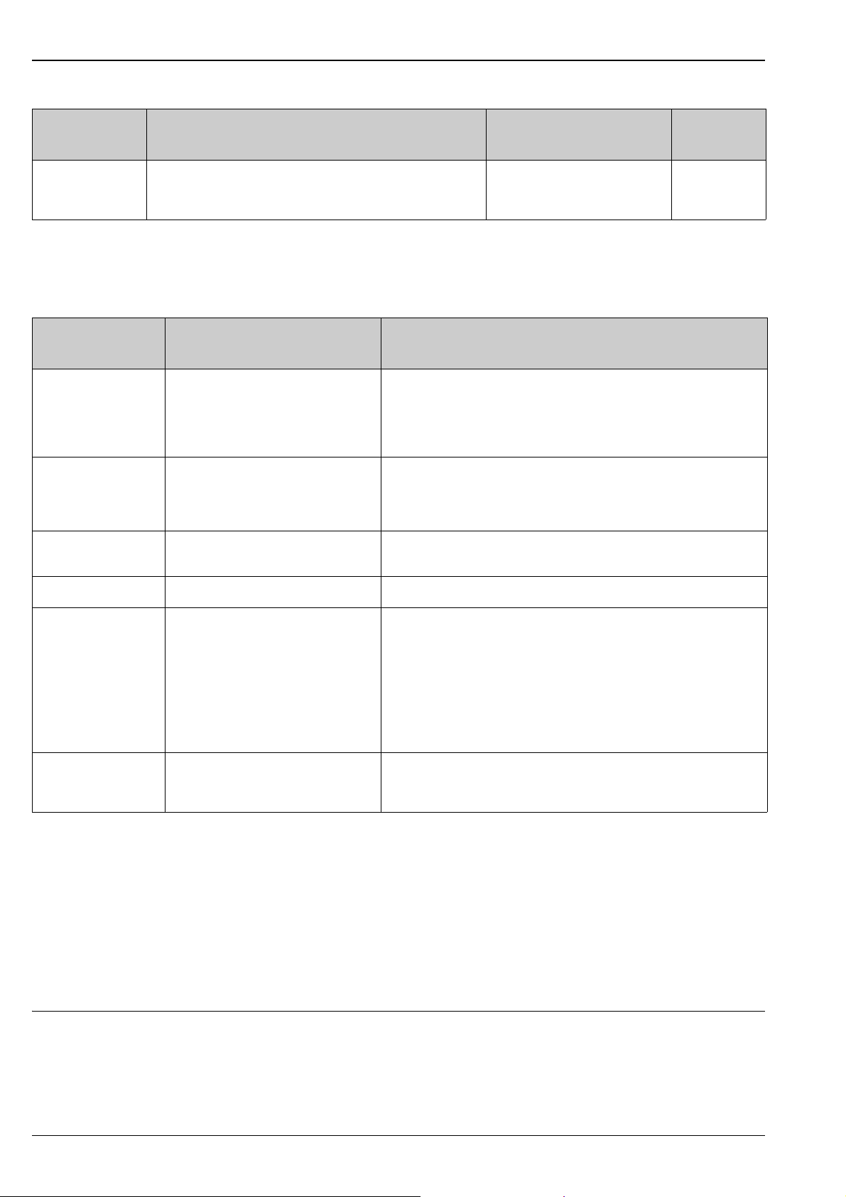
Measured
Measuring range Maximum measured error
variable
Frequency input (I) 0 to 10 kHz, overrange: to 12.5 kHz
0...7 mA = LOW
13...20 mA = HIGH
Maximum input load
Limit values for input voltage and input current as well as cable open circuit detection/line influence/
temperature compensation:
Measured variable Limit values (steady-state,
without destroying input)
Current (I) Maximum permitted input voltage: 2.5 V
Maximum permitted input current: 50 mA
Pulse,
frequency (I)
Maximum permitted input voltage: 2.5 V
Maximum permitted input current: 50 mA
Minimum pulse length: 30 μs
Maximum 13 kHz
Input
of measuring range (oMR)
± 0.01 % oMR Load: 50 Ohm
resistance
Cable open circuit detection/line influence/temperature
compensation
4 to 20 mA range with disengageable cable open circuit detection as per NAMUR
NE43. The following error ranges apply if NE43 is activated:
3.8 mA: underrange (display shows: vvvvvv)
20.5 mA: overrange (display shows: ^^^^^^)
3.6 mA or 21.0 mA: cable open circuit (display: - - - -)
No cable open circuit monitoring
Voltage (U) > 1 V Maximum permitted input voltage: 35 V 1 to 5 V range with disengageable cable open circuit detection:
Voltage (U) 1 V Maximum permitted input voltage: 24 V
Resistance
thermometer (RTD)
Thermocouples (TC) Maximum permitted input voltage: 24 V Cable open circuit detection from 50 kOhm
Measuring current: 1 mA Maximum barrier resistance (or line resistance):
< 0.8 V or > 5.2 V: cable open circuit (display: - - - -)
Max. 200 Ohm (4-wire)
Max. 40 Ohm (3-wire)
Maximum influence of barrier resistance (or line resistance) for Pt100, Pt500 and
Pt1000: 4-wire: ±0.0002%/Ohm, 3-wire: ±0.002%/Ohm
Maximum influence of barrier resistance (or line resistance) for Pt46, Pt50, Cu50,
Cu53 and Cu100: 4-wire: ±0.0006%/Ohm, 3-wire: ±0.006%/Ohm
Influence of line resistance in event of break detection: < 0.001%/Ohm
Error, internal temperature compensation: 2 K
Scan rate
All channels are scanned within 100 ms.
Converter resolution
24 bit
Totalization
The interim value, daily value, weekly value, monthly value, annual value and overall value can be determined
(13-digit, 64 bit).
Digital inputs Number
Standard version: 6 digital inputs
Optional digital card (slot 5): 8 additional digital inputs
6 Endress+Hauser
Page 7

Memograph M
Input level
To IEC 61131-2:
Logical "0" (corresponds to -3 to +5 V), activation with logical "1" (corresponds to +12 to +30 V)
Input frequency
Max. 25 Hz
Pulse length
Min. 20 ms
Input current
Max. 2 mA
Input voltage
Max. 32 V (steady-state, without destroying input)
Selectable functions
Control input, ON/OFF message, pulse counter (13-digit, 64 bit), operating time, message+operating time,
quantity from time.
Functions of the control input: start recording, screensaver on, block setup, block keyboard/navigator, time
synchronization, change group, limit value monitoring on/off, individual LV on/off, start/stop evaluation.
Output
Auxiliary voltage output The auxiliary voltage is provided to activate the digital input (or the sensors) with floating contacts and is
galvanically isolated from the system and the inputs (testing voltage 500 V).
Output voltage:
Approx. 24 V DC, max. 28 V
Output current:
Maximum 300 mA, short-circuit proof, not stabilized
Relay outputs Standard version (power supply slot): 1 alarm relay with changeover contact, 5 relays with NO contact e.g. for
limit value alarms (can be configured as NC contact).
Optional digital card (slot 5): 6 additional relays with NO contact e.g. for limit value alarms (can be configured
as an NC contact).
!
Note!
It is not permitted to mix low voltage and safety extra low voltage (do not mix SELV circuits and low voltage).
Response time:
max. 400 ms
Maximum DC contact load:
30 V / 3 A
Maximum AC contact load:
230 V / 3 A
Analog and pulse outputs Number:
Optional digital card (slot 5): 2 analog outputs which can be operated as current or pulse outputs.
Endress+Hauser 7
Page 8
Analog output (current output):
Output current: 0/4 to 20 mA with 10 % overrange
Max. output voltage: approx. 16 V
Accuracy: 0.1 % of output range
Temperature drift: 0.015 %/K
Resolution: 13 bit
Load: 0 to 500 Ohm
Error signal to NAMUR NE43: 3.6 mA or 21 mA can be configured
Digital output (pulse output):
Output voltage as per IEC 61131-2:
5 V corresponds to LOW
12 V corresponds to HIGH
Short-circuit proof (maximum 25 mA)
Frequency: 0 to 2 kHz
Pulse width: 0.5 to 1000 ms
Accuracy: 0.1 % of output range
Temperature drift: 0.1 %
Load: 1 kOhm
Memograph M
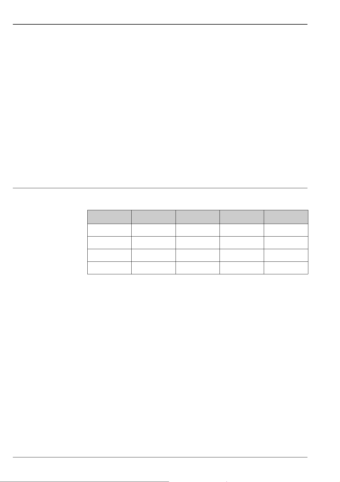
Galvanic isolation All the inputs and outputs are galvanically isolated from one another and tested with the following testing
voltages:
Relay Digital in Analog in Analog out
Relay 2.3 kV 2.3 kV 2.3 kV 2.3 kV
Digital in 2.3 kV 500 V
Analog in 2.3 kV 500 V 500 V 500 V
Analog out 2.3 kV 500 V 500 V 500 V
1) Not galvanically isolated from one another. Galvanic isolation is only available for digital inputs between the power
unit and the optional digital card.
1)
500 V 500 V
8 Endress+Hauser
Page 9
Memograph M
Ethernet
USB
RS 232 / RS 485
Bus Interface
Ch1
Ch2
Ch3
41
…
…
…
…
46
Ch4
31
…
…
…
…
36
21
…
…
…
…
26
11
…
…
…
…
16
Ch5
Ch6
Ch7
81
…
…
…
…
86
Ch8
71
…
…
…
…
76
61
…
…
…
…
66
51
…
…
…
…
56
Ch9
Ch10
Ch11
C1
…
…
…
…
C6
Ch12
B1
…
…
…
…
B6
A1
…
…
…
…
A6
91
…
…
…
…
96
Ch13
Ch14
Ch15
G1
…
…
…
…
G6
Ch16
F1
…
…
…
…
F6
E1
…
…
…
…
E6
D1
…
…
…
…
D6
L/+
N/-
PE
24V
Out
O15
O16
O25
O26
D71
D81
D91
DA1
DB1
DC1
DD1
DE1
GND2
GND2
R11
R12
R13
R41
R42
R51
R52
R61
R62
D11
D21
D31
D41
D51
D61
GND1
+
R21
R22
R31
R32
-
RARBRCRDRERFRGRHRIRJRK
RL
-
+
-
+
-
+
b) 1 V
≤
a)>1V
Rel. max. 250V/3A
+
-
a) 0...5 V, 1...5 V, 0...10 V, +/- 10 V, +/- 30 V
b) 0...1 V, +/- 150 mV, +/- 1 V
L+
N-
PE
100-230 VAC
(±10%)
50/60Hz
12-24 VDC
>5 mA
+
+
_
RTD
I
U
TC
0...20 mA, 4...20 mA, 0...5 mA
J, K, T, N, L, D, C, B, S, R
Umax.=24V
+
_
12-24 VDC
24 V AC/DC
(-10%; +15%)
50/60Hz
24V Out: max. 300 mA
Dx1
+
-
LOW = 0...7 mA
HIGH = 13...20 mA
U max. = 2.5 V
15
69
>30 µs
>20 ms
RS 232
2
2
2
2
3
3
3
3
5
5
5
5
1
1
1
1
5
5
13
13
6
6
14
14
9
9
25
25
7
7
RS 485
RxD/TxD(+)
R
L
RxD/TxD(-)
R=
L
8
9
89
89
89
89
x2x1 x3 x4x5x6
x2x1 x3 x4x5x6
Dx1
GNDx
24V+
Dx1
GNDx
24V-
-
GNDx
Dx1
GNDx
10k
O15
O16
O25
O26
+-+-
12
0...20 mA;
4...20 mA
+-+-
12
Pt46, Pt50, Pt100,
Pt500, Pt1000,
Cu50, Cu53, Cu100
x2x1 x3 x4x5x6 x2x1 x3 x4x5x6
+
-
24 V
x2x1 x3 x4x5x6
R=1.2 k
a)Umax.=35V
b)Umax.=24V
U max. = 2.5 V
(Volt drop 1 V, Ri50 Ohm)≤≤
Further units
Cable
resistance
Power supply
Digital in (D)
To PC: Cable with
9 pol. Sub-D plug
RxD-3 GND-5
TxD-2
To PC: Cable with
25 pol. Sub-D
plug
To modem: Cable with
9 pol. Sub-D socket
To modem: Cable with
25 pol. Sub-D socket
Analog inputs
LED
yellow
LED
green
Pulse/
frequency
Power supply slot
Slot 5
Slot 4
Slot 3
Slot 2
Slot 1 )
Interface slot
(standard)
1-4 (option
analog input 17-20 or digital-I/O (option)
analog input 13-16 (option)
analog input 9-12 (option)
analog input 5-8 (option)
analog input
Analog
outputs (O)
(Selectable in unit setup)
Pulse
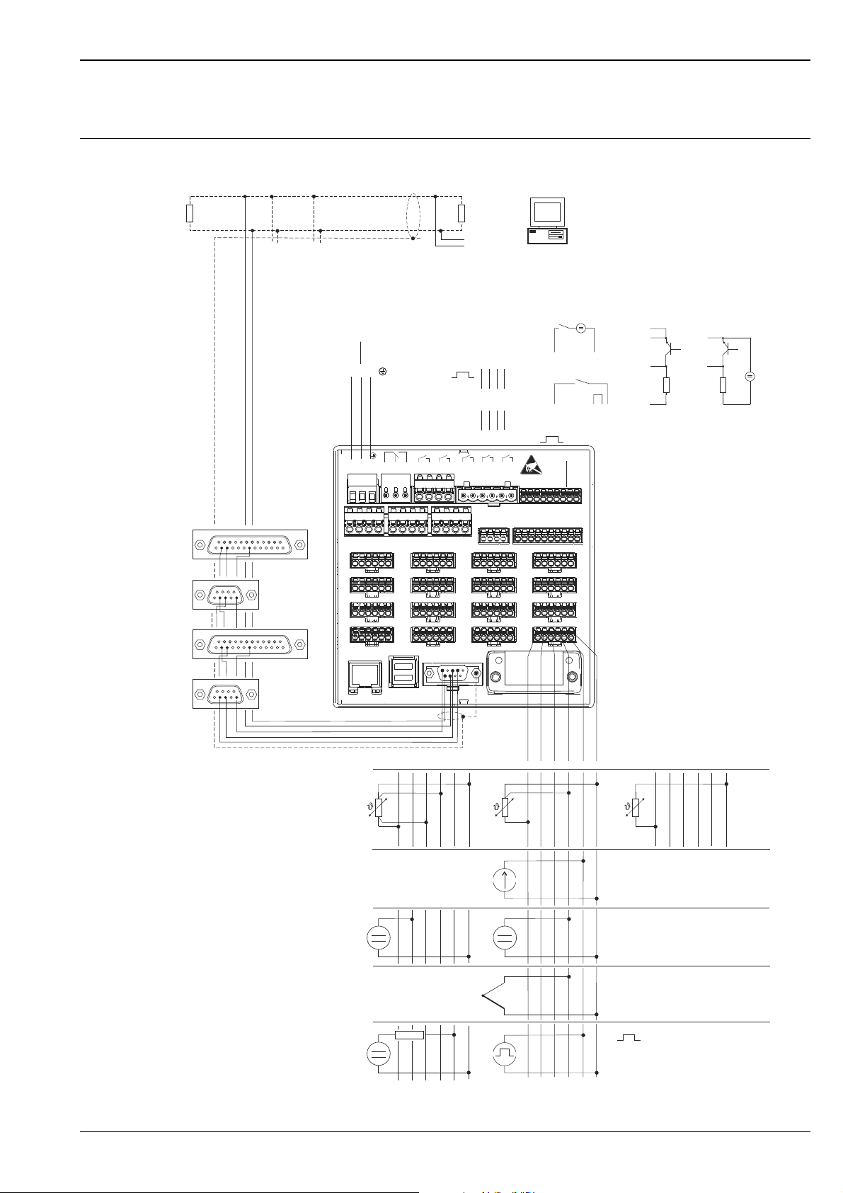
Electrical connection (wiring diagram)
Power supply / terminal diagram
Endress+Hauser 9
Page 10
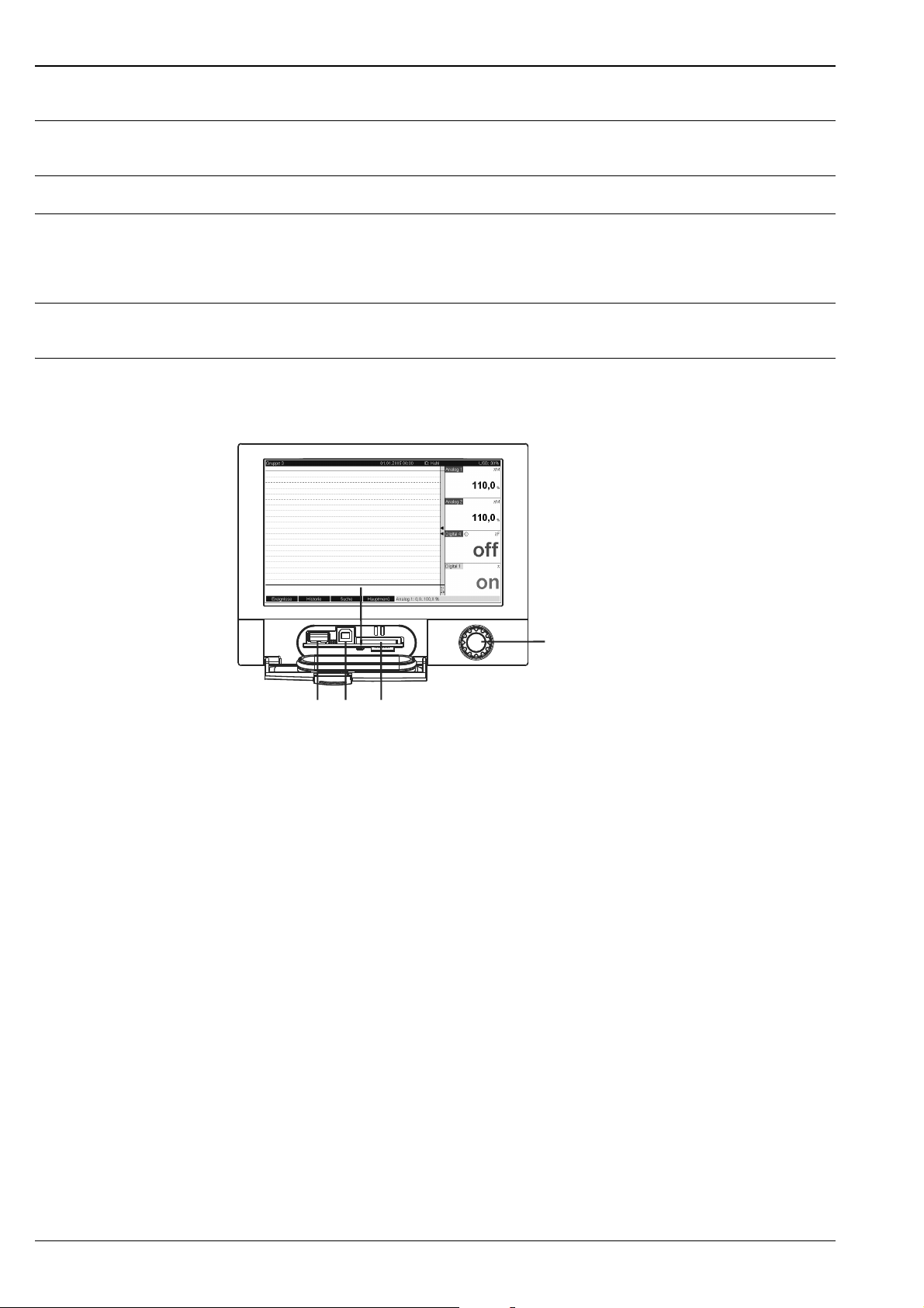
Supply voltage Low voltage power unit: 100...230 VAC (±10%)
3
1 2 4
5
Extra-low voltage power unit: 24 V (-10%; +15%)
Frequency Nominal frequency: 50 / 60 Hz
Cable specification Screw or spring terminal blocks with reverse polarity protection:
Wire cross-section, digital I/O and analog inputs: max. 1.5 mm (14 AWG) (spring terminals)
Wire cross-section, power supply: max. 2.5 mm
Wire cross-section, relays: max. 2.5 mm (13 AWG) (spring terminals)
Power consumption 100...230 V: max. 40 VA
24 V: max. 40 VA
AC/DC
(13 AWG) (screw terminals)
Memograph M
Connection data interface,
communication, operation
USB ports:
USB at the front of the unit
Front of unit with open flap/keyboard
1: USB A socket "host" e.g. for USB memory stick, external keyboard, bar code reader or printer
2: USB B socket "Function" e.g. to connect to PC or laptop
3: LED at SD slot. Yellow LED lit when the unit writes to the SD card or reads it.
4: Slot for SD card
5: Navigator
1 x USB connection, type A (host)
A USB 2.0 connection is available on a shielded USB A socket at the front of the unit. A USB stick as a memory
medium, a keyboard, a USB hub, a bar code reader or a printer (PCL5c or higher) can be connected to this
interface.
1 x USB connection, type B (function)
A USB 2.0 connection is available on a shielded USB B socket at the front of the unit. This can be used to
connect the unit for communication with a laptop for example.
USB at the rear of the unit
2 x USB connection, type A (host) (interface slot)
Two USB 2.0 connections are available on shielded USB A sockets at the rear of the unit. A USB stick as a
memory medium, a keyboard, a USB hub, a bar code reader or a printer (PCL5c or higher) can be connected
to these interfaces.
!
Note!
• The USB 2.0 connections are compatible with USB 1.1, i.e. communication is possible.
• The assignment of the USB ports corresponds to the standard such that shielded standard cables with a
maximum length of 3 meters (9.8 ft) can be used here.
• Multiple USB sticks cannot be operated simultaneously. The USB stick that was first connected has priority.
10 Endress+Hauser
Page 11

Memograph M
!
USB printer reference list:
HP Color LaserJet CP1515n; Kyocera FS-C5015N
Note!
The printer must support PCL5c (or higher). GDI printers are not supported!
USB bar code reader reference list:
Datalogic Gryphon D230; Metrologic MS5100 Eclipse Series; Symbol LS2208
Ethernet interface (interface slot):
An IEEE 802.3-compatible connection is available on a shielded RJ45 plug connector on the rear of the unit as
the network connection. This can be used to connect the unit with a hub or switch to units in an office
environment. For safe spacing distances, the office equipment standard EN 60950 must be observed. The
assignment corresponds to a standards-compliant MDI port (AT&T258) such that a shielded 1:1 cable with a
maximum length of 100 meters (328 ft) can be used here. The Ethernet port is designed as 10/100–BASE–T.
Direct connection to a PC is possible with a crossover cable. Half-duplex and full-duplex data transfer is
supported. Alternatively, a GPRS modem can also be connected to the Ethernet interface.
The unit can be used in the network as a "Web server". Two Ethernet function LEDs on the rear of the unit.
Serial RS232/RS485 interface (interface slot):
A combined RS232/RS485 connection is available on a shielded SUB D9 socket at the rear of the unit. This
can be used for data or program transfer and to connect a modem. For communication via modem, we
recommend an industrial modem with a watchdog function.
The following baudrates are supported: 1200, 2400, 4800, 9600, 19200, 38400, 57600, 115200
Max. line length with shielded cable: 2 m (6.6 ft) (RS232) or 1000 m (3281 ft) (RS485)
Both interfaces are galvanically isolated from the system.
The RS232/RS485 interfaces cannot be used simultaneously.
Remote interrogation with analog or GSM/GPRS wireless modem:
• Analog modem:
An analog modem (e.g. Devolo or WESTERMO), which is connected to the RS232 interface with a special
modem cable (see Accessories RXU10-A1), is recommended for industry.
• GSM/GPRS wireless modem:
A GSM/GPRS wireless modem (e.g. Siemens, INSYS or WESTERMO, incl. antenna and power unit), which
is connected to the RS232 interface with a special modem cable (RXU10-A1 accessory), is recommended for
industry. Important: the wireless modem needs a SIM card and data transfer subscription. In addition, it must
be possible to deactivate the PIN prompt.
Bus interface (interface slot, optional)
• PROFIBUS–DP slave:
The unit can be integrated into a fieldbus system as per the PROFIBUS–DP standard by means of the
PROFIBUS-DP interface. Up to 40 analog inputs and 14 digital inputs can be transmitted via PROFIBUS–DP
and stored in the unit. For bidirectional communication in cyclic data transfer.
Baudrate: maximum 12 Mbit/s
• Modbus RTU slave:
Up to 40 analog inputs and 14 digital inputs can be transmitted via Modbus and stored in the unit.
• Ethernet Modbus TCP slave:
Connection to SCADA systems (Modbus master). Up to 40 analog inputs and 14 digital inputs can be
transmitted via Modbus and stored in the unit.
Endress+Hauser 11
Page 12
Performance characteristics
195.2
(7.69)
149.2
(5.87)
Y
X
138
(5.43 )
+1
+0.04
7 (0.28)
138 (5.43)
196.2 (7.72)
58.2 (2.29)
138 (5.43)
156.2 (6.15)
18.2 (0.72)
157.8 (6.21)
141 (5.55)
105.5 (4.15)
23.3 (0.92)
35.1
(1.38)
138 (5.43)
5
(0.2)
192 (7.56)
Memograph M
Reference operating conditions
Ambient temperature: 25 °C ± 5 K (77 °F ± 9 °F)
Air humidity: 55 % ± 10 % r.h.
Maximum measured error (See Input)
Temperature drift Cu50, Cu53, Cu100, Pt46 and Pt50: max. ± 0.02 %/K (of measuring range)
All other ranges: max. ± 0.01 %/K (of measuring range)
Long-term drift To IEC 61298-2: max. ± 0.1 %/year (of measuring range)
Installation
Orientation Operating position as per DIN 16 257, NL 90 ± 30°
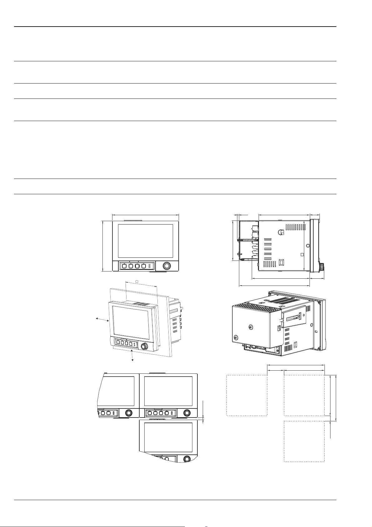
Installation instructions Panel cutout and installation / design, dimensions:
All dimensions in mm or (inch)
12 Endress+Hauser
Page 13
Memograph M
293.4 mm (11.55 “)
236 mm (9.3 “)
188 mm (7.4 “)
173 mm (6.8 “)
210.6 mm (8.3“)
184 mm (7.2 “)
173 mm (6.8 “)
293.4 mm (11.55 “)
236 mm (9.3 “)
!
• Installation depth without terminal cover: approx. 158 mm (6.22") (incl. terminals and fastening clips)
• Installation depth with terminal cover: approx. 197 mm (7,76")
• Panel cutout: 138
• Panel thickness: 2 to 40 mm (0.08 to 1.58")
• Max. viewing angle range: from the display central axis 50° in all directions
• Securing to DIN 43 834
Note!
• A distance of min. 7 mm (0.28 inch) between the devices has to be observed if aligning the devices in the
Y-direction (vertically above one another).
• The devices can be arranged horizontally beside one another in the X direction without any spacing between
the devices.
• The grid dimension of the panel cutouts for multiple devices must be min. 196.2 mm (7.72") horizontally
and min. 156.2 mm (6.15") vertically (tolerance not considered).
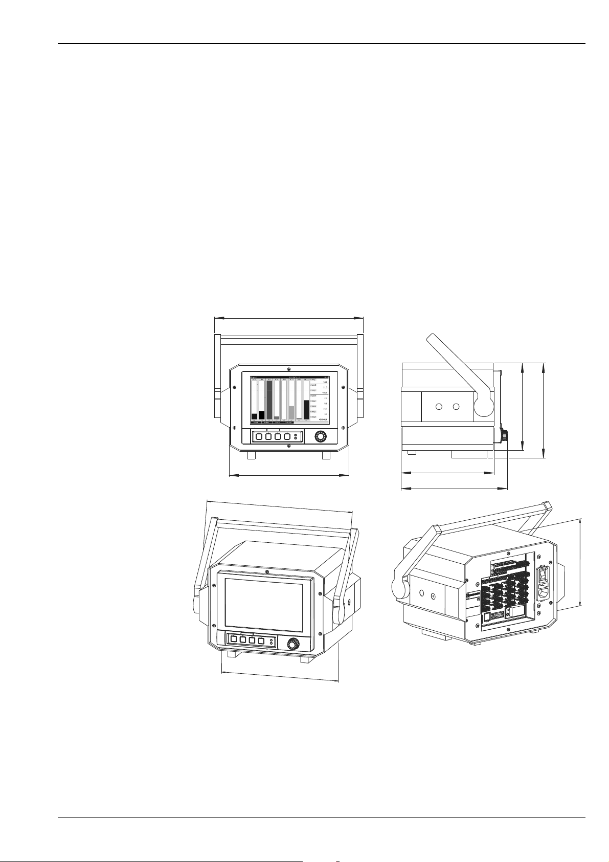
Design, dimensions desk top housing:
+1
x 138+1 mm (5.43
+0.04
x 5.43
+0.04
")
All dimensions in mm or (inch)
Endress+Hauser 13
Page 14

Environment
Ambient temperature range -10 to 50 °C (14 to 122 °F)
Storage temperature -20 to +60 °C (-4 to 140 °F)
Climate class To IEC 60654-1: B1
Degree of protection Front-panel IP65 (IEC 60529, Cat. 2) NEMA 4
Rear-panel IP20 (IEC 60529, Cat. 2)
Electrical safety IEC 61010-1, protection class I
Low voltage: overvoltage category II
Environment < 3000 m (< 9843 ft) above MSL (mean sea level)
Memograph M
Electromagnetic compatibility (EMC)
Interference immunity:
To IEC 61326 (industrial environment) and NAMUR NE21:
• ESD (electrostatic discharge): IEC 61000-4-2 severity 3 (6/8 kV)
• HF field (electromagnetic interference fields): IEC 61000-4-3: severity 3 (10 V/m)
• Burst (quick transient disturbance variables): IEC 61000-4-4 severity 3 (1 kV signal, 2 kV power supply)
• Surge on power line: IEC 61000-4-5: 2 kV asymmetrical, 1 kV symmetrical
• Surge on signal line: IEC 61000-4-5: 1 kV asymmetrical (with external protection element)
• Conducted HF: IEC 61000-4-6: 150 kHz to 80 MHz, 10 V
• Power failure: IEC 61000-4-11 (> 20 ms/0%)
• Voltage variation: IEC 61000-4-11 (40% / 0%)
Emission:
To IEC 61326: Class A (operation in industrial environment)
Interference voltage:
Power cable: To CISPR 16-1/-2: Class A
Interference current:
Ethernet cable: To EN 50022: Class A
Interference field intensity:
Housing/all connections: To CISPR 16: Class A
Interference voltage suppression:
• Common mode interference voltage suppression: IEC 61298-3:
Analog inputs: 80 dB at 60 V and 50 Hz / 60 Hz
• Push-pull interference voltage suppression: IEC 61298-3:
Analog inputs: 40 dB at 50 Hz / 60 Hz, for measuring range/10
Mechanical construction
Design, dimensions See Installation
Weight • Panel-mounted instrument, maximum configuration: approx. 2.7 kg (5.9 lb)
• Desk top housing, maximum configuration: approx. 4.4 kg (9.6 lb)
Materials • Front: GD-Z410 (zinc diecasting) (border area powder-coated)
• Display panel (front): transparent plastic (Makrolon
• Flap (front): plastic (ABS UL94-V2)
• Membrane keypad: polyester (PC-ABS UL94-V2)
• Jog/shuttle dial ("navigator"): plastic (ABS UL94-V2)
14 Endress+Hauser
®
)
Page 15
Memograph M
• Intermediate frame (front to panel): plastic (PA6-GF15 UL94-V2)
• Casing: St 12 ZE (galvanized sheet steel)
• Rear panel: St 12 ZE (galvanized sheet steel)
!
Note!
All materials are free from silicone.
Desk top housing:
• Half shell housing: Sheet steel, electrolytic galvanized (powder-coated)
• Side profiles: extruded aluminum sheath (powder-coated)
• Profile ending: pigmented Polyamide
• Housing feet: pigmented Polyamide, glass fiber reinforced
Human interface
Display elements Type:
Wide-screen TFT color graphic display
Size (Screen size):
178 mm (7")
Resolution:
Wide VGA 384,000 pixels (800 x 480 pixels)
Background illumination:
50,000 h half value time (= half brightness)
Number of colors:
262,000 viewable colors, 256 colors used
Viewing angle:
Max. viewing angle range: from the display central axis 50° in all directions
Screen display:
• Users can choose between black or white for the background color
• Active channels can be assigned to up to 10 groups. For the purposes of clear identification, these groups are
given a name e.g. "Temperatures boiler 1" or "Daily average values of all boilers"
• Scales linear or logarithmic
• Replay function: rapid callup of history data with zoom function
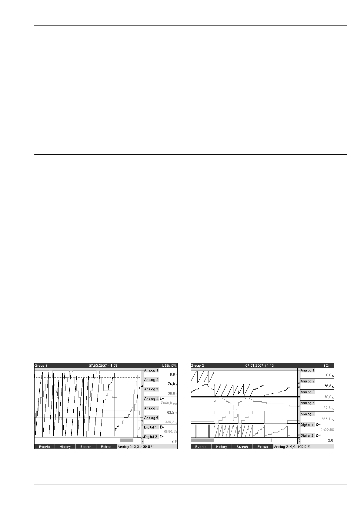
• Preformatted screen display, such as horizontal or vertical curves, bar graphs, instrument display, circular
chart or digital display, allow rapid and uncomplicated commissioning:
Curve display Curve in ranges
Endress+Hauser 15
Page 16
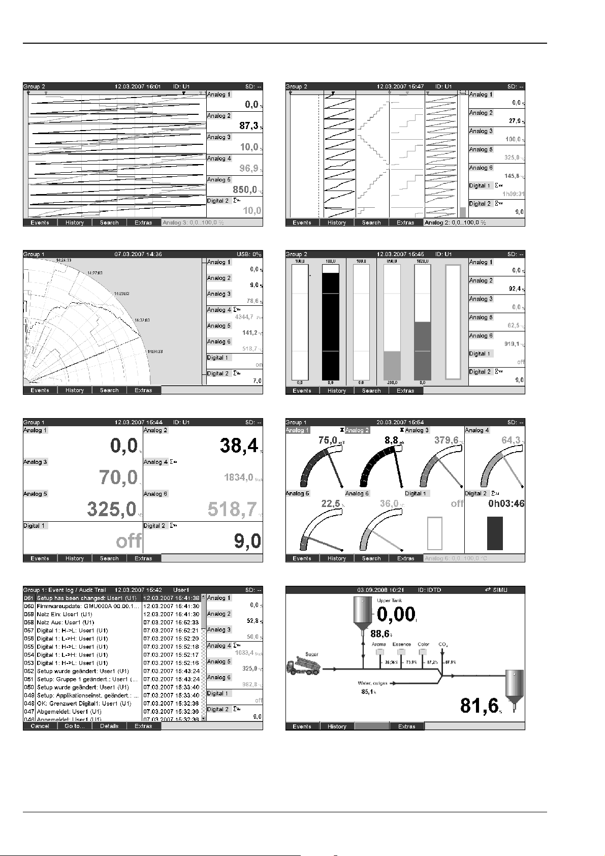
Waterfall Waterfall in ranges
Memograph M
Circular chart Bar graph
Digital display Instrument display
Event log Process display
16 Endress+Hauser
Page 17
Memograph M
Operating elements Unit keyboard:
Option of operation and configuration via navigator (jog/shuttle dial) and 4 softkeys on the front side in
interactive dialog with the screen, or using PC software supplied. Integrated online help displayed at the press
of a button.
External keyboard:
Additionally an external keyboard for operation and configuration can be connected to the equipment (USB
type A " Host"). Radio keyboards are not supported.
Saving data Memory cycle:
• Selectable memory cycle: off, 100ms, 1s / 2s / 3s / 4s / 5s / 10s / 15s / 20s / 30s / 1min / 2min / 3min
/ 4min / 5min / 10min / 30min / 1h
• High-speed saving (100ms) can be configured for up to 8 channels of group 1
Measured data storage, internal memory:
• Setup data memory, measured data memory and program memory: permanent backup of setup data and
measured data in internal Flash memory with power failure protection (256 MB, nonvolatile)
• Data buffering and RTC buffering with lithium cell (buffering for 6 years; replace after 10 years).
• Even after being exported to a USB stick or SD card, measured data remain in the unit for a long time and
can be reexported. This is important if the external data storage unit is lost or for official audits.
• Plant monitoring functions with operated hours counter, calibration monitoring, monitoring of storage
medium exchange and other functions for monitoring the unit status.
External memory:
• Cyclic copy of the measured data for archiving on SD card (secure digital memory card)
• SD cards supported: 256 MB and 512 MB. Only use "Industrial Grade" SD cards (see Accessories).
• USB sticks supported: 256 MB, 512 MB, 1 GB and 2 GB. It cannot be ensured that USB sticks from all
manufacturers will work perfectly. For this reason, an "Industrial Grade" SD card is recommended for safe
data recording (see Accessories).
• A yellow LED beside the SD slot indicates data access. The SD card may not be removed while this LED is
lit. Risk of losing data!
Typical recording length:
Prerequisites for following tables:
• No limit value violation/event storage
• Digital input not used
• Signal analysis deactivated
Note!
!
Frequent entries in the event log reduce the memory availability!
Internal memory 256 MB (weeks, days, hours):
Analog inputs Memory cycle 5
min.
1 7211, 5, 16 1869, 5, 2 957, 4, 15 324, 3, 11 32, 3, 18
4 3169, 2, 5 718, 6, 20 363, 5, 5 121, 4, 1 12, 1, 9
Memory cycle 1
min.
Memory cycle
30 s.
Memory cycle
10 s.
Memory cycle 1
s.
12 1198, 3, 23 254, 6, 7 128, 2, 8 42, 6, 18 4, 2, 3
20 739, 0 ,4 155, 2, 22 78, 0, 5 26, 0, 18 2, 4, 7
Endress+Hauser 17
Page 18
External SD card 254 MB (weeks, days, hours):
Memograph M
Analog inputs Memory cycle 5
min.
1 9703, 3, 19 2515, 5, 3 1288, 3, 19 436, 4, 7 43, 5, 11
4 4264, 2, 8 967, 2, 18 489, 2, 22 163, 4, 3 16, 2, 21
12 1612, 4, 19 342, 6, 19 172, 4, 14 57, 5, 17 5, 5, 13
20 994, 2, 13 209, 0, 20 104, 6, 22 35, 0, 22 3, 3, 15
Calculating the recording duration:
The recording duration is calculated using the "storage calculator" (can be found in the "Tools" directory on the
PC software CD–ROM supplied).
Pixels available for measured value curves:
Display method Pixel
Curve display with instantaneous value display 566
Curve display without instantaneous value display 786
Waterfall 409
Memory cycle 1
min.
Memory cycle
30 s.
Memory cycle
10 s.
Memory cycle 1
s.
Circular chart Not available
!
Real time clock (RTC) Configurable summer time/normal time automated system
Remote control,
communication
Note!
1 pixel = 1 measuring date
With 100 ms storage cycle -> 1 s = 10 pixels
Power reserve: buffering via lithium battery (buffering 6 years; replace after 10 years)
Deviation: < 10 min./year
Time synchronization possible via PC software supplied or via control input.
• USB interface (front-panel), Ethernet interface and additional RS232/RS485 interface (rear)
• OPC server (3.0) for direct data exchange with databases or/and visualization systems
• Integrated Internet page (Web server) allows password-protected access to the device with every PC (e.g.
for displaying the measured data)
• DHCP-enabled (dynamic allocation of an IP address)
• Device-internal summer time/winter time changeover
• Configuring and archiving the device settings with SD card, USB stick or with PC software supplied via rearmounted serial interface RS232/RS485 (e.g. modem), Ethernet, or USB port.
Functions of the PC software supplied:
• Device configuration, measured data visualization, measured data administration and measured data export
• Export the measured data of individual channels to separate files or several channels to one file
18 Endress+Hauser
Page 19

Memograph M
Certificates and approvals
CE mark The measuring system meets the legal requirements of the EC directives. The manufacturer confirms successful
testing of the device by affixing the CE mark.
UL-listed for Canada and USA The device has been examined by Underwriters Laboratories Inc. (UL) in compliance with the UL 61010-1
and CSA C22.2 No. 61010-1 standards and has been UL-listed under the number E225237.
Milk pasteurization approval The device has been examined by the Technical University of Munich (TUM) in compliance with the test
guidelines for measuring, control and safety devices for milk heating plants and has been listed under the
number W-M1/07.
Other standards and guidelines
Electronic recording/ electronic signature
CSA approval
CAN/CSA-C22.2 No. 61010-1-04 Safety requirements for electrical equipment for measurement, control, and
laboratory use - General requirements, Second Edition.
FDA 21 CFR11
The device meets the requirements of the "Food and Drug Administration" for electronic recording/electronic
signature.
Endress+Hauser 19
Page 20
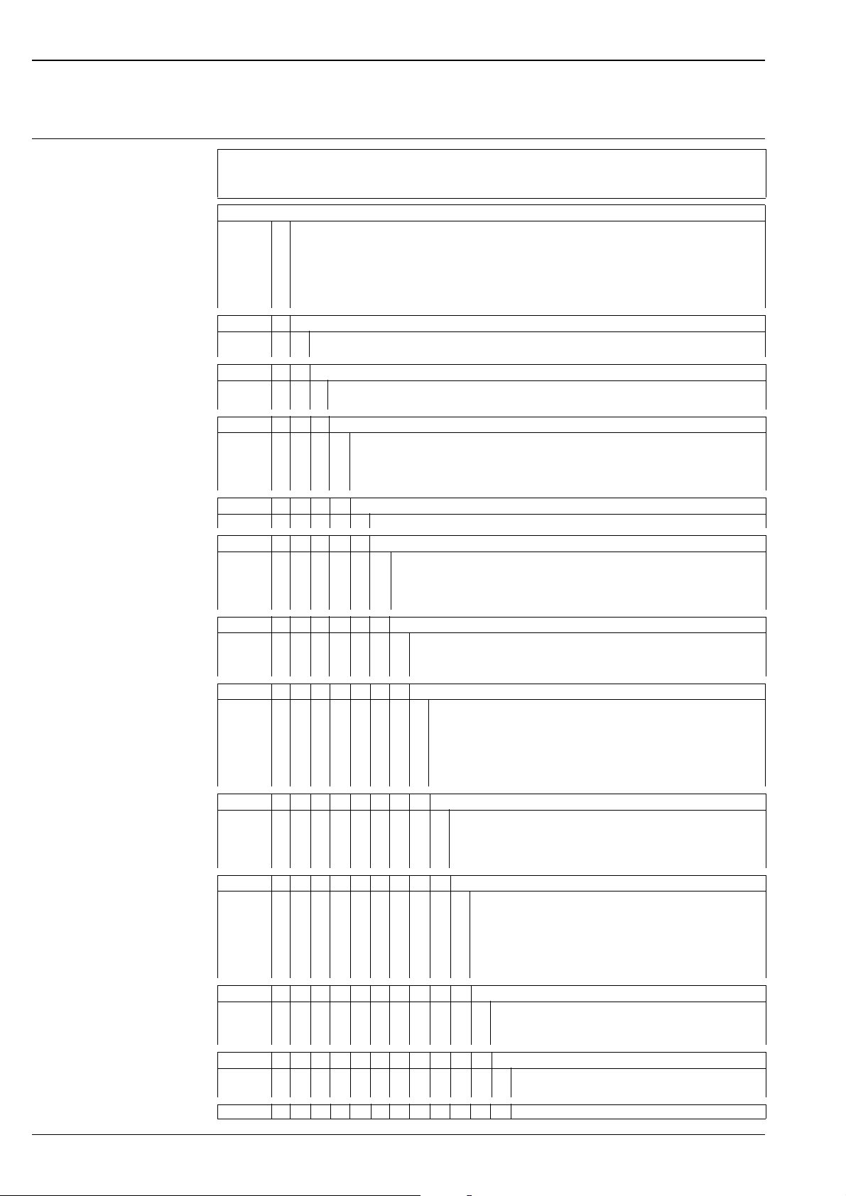
Ordering information
Memograph M
Product structure
Basic features:
7" TFT color graphic display, 800 x 480 pixels; 256 MB internal memory; Secure digital SD slot; 24 V auxiliary output voltage
Security package: person-specific access authorization and electronic signature (FDA 21 CFR 11)
Interactive dialog operation with navigator and 4 operating keys; 100 limit values; Integration, signal evaluation;
Signal input
A Not selected
B 4 multifunctional inputs (U, I, TC, RTD, pulse/frequency input 10 kHz)
C 8 multifunctional inputs (U, I, TC, RTD, pulse/frequency input 10 kHz)
D 12 multifunctional inputs (U, I, TC, RTD, pulse/frequency input 10 kHz)
E 16 multifunctional inputs (U, I, TC, RTD, pulse/frequency input 10 kHz)
F 20 multifunctional inputs (U, I, TC, RTD, pulse/frequency input 10 kHz)
Digital input; output
126 x digital, 25 Hz; 6 x relay (1 x SPDT + 5 x SPST)
14 x digital, 25 Hz; 12 x relay (1 x SPDT + 11 x SPST), 2 x analog output
Power supply
1 100-230 V AC (+/-10%), 50/60 Hz
2 24 V (-10%; +15%), AC/DC
Communication
1 Not selected
2 Profibus DP slave, max. 40 x analog, 14 x digital
3 Modbus RTU, max. 40 x analog, 14 x digital
4 Modbus TCP, max. 40 x analog, 14 x digital
Interface
B Ethernet, RS232/485, 1 x USB function (front), 1 x USB host (front), 2 x USB host (rear)
Additional option
1 Not required
2 Factory calibration certificate
3 IQ-/OQ-Template +factory calibration certificate +software backup
4 IQ-/OQ-Template for PROFIBUS/Modbus communication +software backup
Memory medium
A without SD card
B SD card 256 MB
C SD card, 512 MB
Housing
1 Panel 149 x 195 mm (5.87 x 7.68"), IP65, NEMA 4
2 Table version, shockproof connector
3 Table version, US connector
4 Table version, Swiss connector
5 Field housing, IP65, NEMA 4x
6 Panel 149 x 195 mm (5.87 x 7.68"), + terminal cover, IP65, NEMA 4
Operation Language
A Central/western Europe (German, English, French, Spanish, Italian, Dutch)
B Eastern European (German, English, Polish, Russian, Czech)
C America (German, English, French, Spanish, Portugese)
D Asia (German, English, Japanese, Chinese, Korean)
Software
1 Basic version incl. security package
2 Mathematics package
3 Tele Alarm + Mathematics
4 Batch + Mathematics
5 Waste water + Storm overflow + Tele Alarm + Mathematics
6 Energy software, water+steam + Mathematics
Version
A Standard
B Preset application
C Accuracy calculation application
Approval
1 Non-hazardous area
2 Milk pasteurization, TU Munich
RSG40- B Order code
20 Endress+Hauser
Page 21
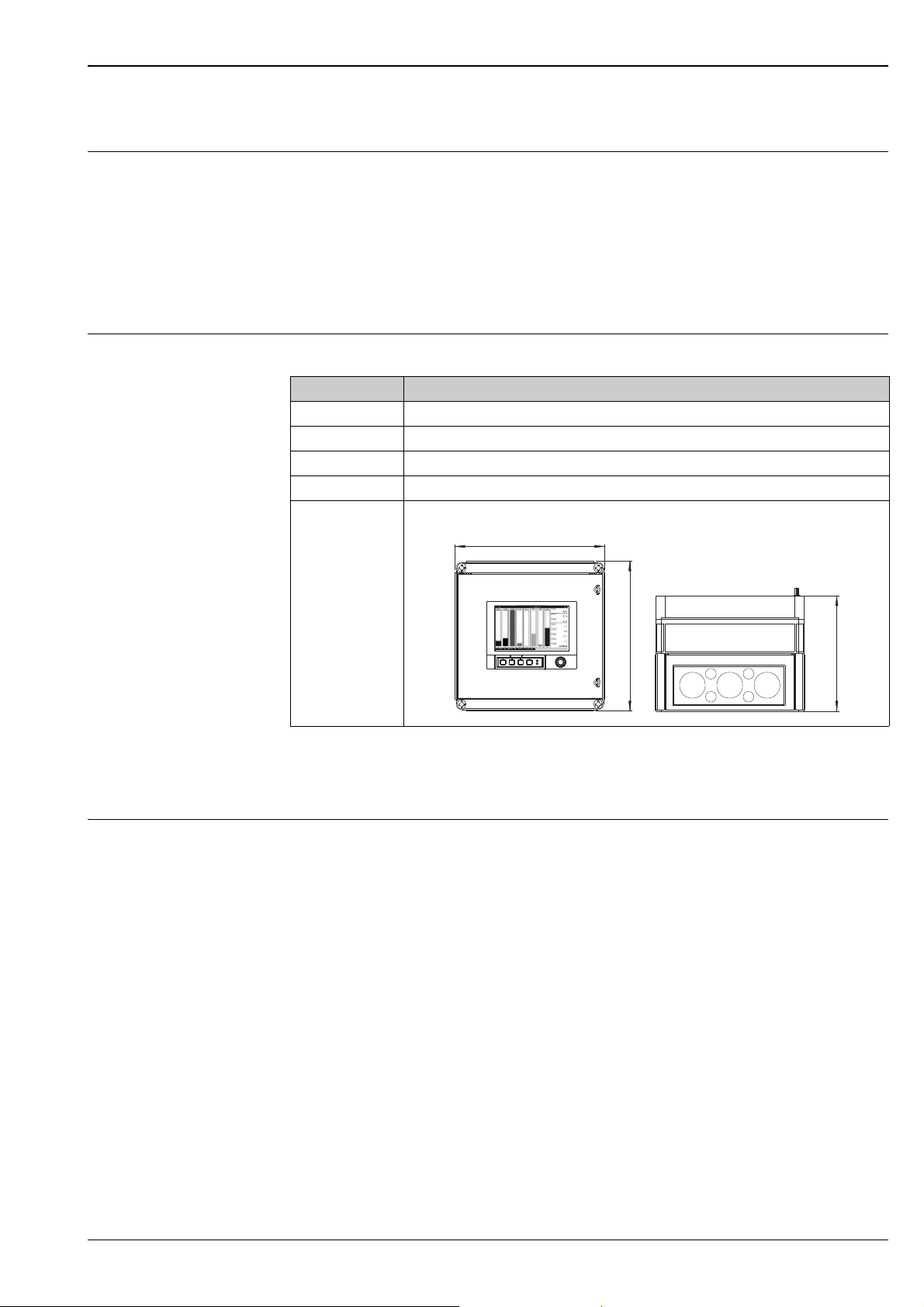
Memograph M
320 mm (12.6“)
320 mm (12.6“)
254 mm (10“)
Accessories
Scope of delivery • Device (with terminals, as per your order)
• 2 fastening clips
• USB cable, length 1.5 m (4.9 ft)
• Optional secure digital (SD) card (card not in device but is supplied.)
• PC operating and configuration software on CD-ROM
• Delivery note
• Multilanguage Brief Operating Instructions as hard copy
• Multilanguage Operating Instructions on CD-ROM
Anything missing? Then please inform your supplier.
Accessories The following accessories are available:
Order code Accessory
71007465 Cable USB-A - USB-B, 2 m (6.6 ft)
71038635 "Industrial Grade" SD memory card 256 MB
71044060 "Industrial Grade" SD memory card 512 MB
RXU10-A1 RS232 cable set for connection with PC or modem, standard
RSG40A-H1 Field housing, IP65/NEMA 4x
Documentation
Recording technology brochure (FA014R09en)
Technical Information (TI133R09en)
Operating Instructions (BA247R09en)
Brief Operating Instructions (KA248R09)
Operating Instructions Supplementary Description "PROFIBUS DP" (BA256R09)
Operating Instructions Supplementary Description "Modbus RTU / TCP" (BA260R09)
Operating Instructions Supplementary Description "Überwachung von Milcherhitzeranlagen"
(BA261R09de)
Operating Instructions Supplementary Description "Energy, water+steam" (BA266R09)
Operating Instructions Supplementary Description "Batch software" (BA267R09)
Operating Instructions Supplementary Description "Tele alarm" (BA268R09)
Operating Instructions Supplementary Description "Waste water / storm water overflow tank (RÜB)"
(BA269R09)
Endress+Hauser 21
Page 22
Instruments International
Endress+Hauser
Instruments International AG
Kaegenstrasse 2
4153 Reinach
Switzerland
Tel. +41 61 715 81 00
Fax +41 61 715 25 00
www.endress.com
[email protected]
TI133R/09/en/05.10
71035347
FM+SGML 6.0 ProMoDo
 Loading...