

Endress+Hauser Liquisys M CCM223, Liquisys M CCM253 Operating Instructions Manual

Products Solutions Services
BA00214C/07/EN/14.13
71212626
valid as of:
Software-version 2.40
Operating Instructions
Liquisys M CCM223/253
Transmitter for Free Chlorine, Chlorine Dioxide and Total
Chlorine

Endress+Hauser
About this document
Safety messages
The structure, signal words and safety colors of the signs comply with the specifications of
ANSI Z535.6 ("Product safety information in product manuals, instructions and other
collateral materials").
Symbols
Safety message structure Meaning
DANGER
!
Cause (/consequences)
Consequences if safety
message is not heeded
‣ Corrective action
This symbol alerts you to a dangerous situation.
Failure to avoid the situation will result in a fatal or serious
injury.
WARNING
!
Cause (/consequences)
Consequences if safety
message is not heeded
‣ Corrective action
This symbol alerts you to a dangerous situation.
Failure to avoid the situation can result in a fatal or serious
injury.
CAUTION
!
Cause (/consequences)
Consequences if safety
message is not heeded
‣ Corrective action
This symbol alerts you to a dangerous situation.
Failure to avoid this situation can result in minor or
medium injury.
NOTICE
Cause/situation
Consequences if safety
message is not heeded
‣ Action/note
This symbol alerts you to situations that can result in
damage to property and equipment.
Additional information, tips
Permitted or recommended
Forbidden or not recommended

Liquisys M CCM223/253
Endress+Hauser 3
Table of contents
1 Basic safety instructions . . . . . . . . . . . . . 5
1.1 Requirements for the personnel . . . . . . . . . . . . . . . 5
1.2 Designated use . . . . . . . . . . . . . . . . . . . . . . . . . . . . . 5
1.3 Workplace safety . . . . . . . . . . . . . . . . . . . . . . . . . . . 5
1.4 Operational safety . . . . . . . . . . . . . . . . . . . . . . . . . . . 5
1.5 Product safety . . . . . . . . . . . . . . . . . . . . . . . . . . . . . . 6
1.6 Electrical symbols . . . . . . . . . . . . . . . . . . . . . . . . . . . 6
2 Incoming acceptance and product
identification . . . . . . . . . . . . . . . . . . . . . . 7
2.1 Incoming acceptance . . . . . . . . . . . . . . . . . . . . . . . . 7
2.2 Scope of delivery . . . . . . . . . . . . . . . . . . . . . . . . . . . . 7
2.3 Product identification . . . . . . . . . . . . . . . . . . . . . . . . 8
2.3.1 Nameplate . . . . . . . . . . . . . . . . . . . . . . . . . . . 8
2.3.2 Identifying the product . . . . . . . . . . . . . . . . 8
2.4 Certificates and approvals . . . . . . . . . . . . . . . . . . . . 8
2.4.1 CE mark . . . . . . . . . . . . . . . . . . . . . . . . . . . . . 8
2.4.2 CSA general purpose . . . . . . . . . . . . . . . . . . 8
3 Mounting. . . . . . . . . . . . . . . . . . . . . . . . . . 9
3.1 Quick installation guide . . . . . . . . . . . . . . . . . . . . . . 9
3.1.1 Measuring system . . . . . . . . . . . . . . . . . . . . 9
3.2 Installation conditions . . . . . . . . . . . . . . . . . . . . . 11
3.2.1 Field instrument . . . . . . . . . . . . . . . . . . . . 11
3.2.2 Panel-mounted instrument . . . . . . . . . . . 12
3.3 Installation instructions . . . . . . . . . . . . . . . . . . . . 13
3.3.1 Field instrument . . . . . . . . . . . . . . . . . . . . 13
3.3.2 Panel-mounted instrument . . . . . . . . . . . 16
3.4 Post-installation check . . . . . . . . . . . . . . . . . . . . . 16
4 Electrical Connection . . . . . . . . . . . . . . . 17
4.1 Wiring . . . . . . . . . . . . . . . . . . . . . . . . . . . . . . . . . . 17
4.1.1 Connecting supply voltage . . . . . . . . . . . 17
4.1.2 Electrical connection version 1 . . . . . . . 18
4.1.3 Electrical connection version 2 . . . . . . . 19
4.1.4 Device connection . . . . . . . . . . . . . . . . . . . 20
4.1.5 Measuring cable and sensor connection 22
4.1.6 Three-point step controller for
Cl2 / ClO2 / total chlorine . . . . . . . . . . . . 26
4.1.7 Alarm contact . . . . . . . . . . . . . . . . . . . . . . 26
4.2 Post-connection check . . . . . . . . . . . . . . . . . . . . . 26
5 Operability. . . . . . . . . . . . . . . . . . . . . . . . 27
5.1 Quick operation guide . . . . . . . . . . . . . . . . . . . . . 27
5.2 Display and operating elements . . . . . . . . . . . . . 27
5.2.1 Display . . . . . . . . . . . . . . . . . . . . . . . . . . . . 27
5.2.2 Operating elements . . . . . . . . . . . . . . . . . 28
5.2.3 Key assignment . . . . . . . . . . . . . . . . . . . . 29
5.3 Local Operation . . . . . . . . . . . . . . . . . . . . . . . . . . . 31
5.3.1 Automatic/manual mode . . . . . . . . . . . . 31
5.3.2 Operating concept . . . . . . . . . . . . . . . . . . 32
6 Commissioning . . . . . . . . . . . . . . . . . . . 34
6.1 Function check . . . . . . . . . . . . . . . . . . . . . . . . . . . . 34
6.2 Switching on . . . . . . . . . . . . . . . . . . . . . . . . . . . . . . 34
6.3 Quick start-up . . . . . . . . . . . . . . . . . . . . . . . . . . . . . 36
6.4 System configuration . . . . . . . . . . . . . . . . . . . . . . . 38
6.4.1 Setup 1 (chlorine/chlorine dioxide) . . . . . 38
6.4.2 Setup 2 (pH/ORP and temperature) . . . . 40
6.4.3 Current input . . . . . . . . . . . . . . . . . . . . . . . 43
6.4.4 Current outputs . . . . . . . . . . . . . . . . . . . . . 46
6.4.5 Monitoring functions . . . . . . . . . . . . . . . . 50
6.4.6 Check . . . . . . . . . . . . . . . . . . . . . . . . . . . . . . 51
6.4.7 Relay contact configuration . . . . . . . . . . . 55
6.4.8 Service . . . . . . . . . . . . . . . . . . . . . . . . . . . . . 69
6.4.9 E+H Service . . . . . . . . . . . . . . . . . . . . . . . . . 70
6.4.10 Interfaces . . . . . . . . . . . . . . . . . . . . . . . . . . 71
6.5 Communication . . . . . . . . . . . . . . . . . . . . . . . . . . . . 71
6.6 Calibration . . . . . . . . . . . . . . . . . . . . . . . . . . . . . . . . 72
7 Diagnostics and troubleshooting . . . . 76
7.1 Troubleshooting instructions . . . . . . . . . . . . . . . . 76
7.2 System error messages . . . . . . . . . . . . . . . . . . . . . 76
7.3 Process-specific errors . . . . . . . . . . . . . . . . . . . . . . 79
7.4 Instrument-specific errors . . . . . . . . . . . . . . . . . . . 83
8 Maintenance . . . . . . . . . . . . . . . . . . . . . 85
8.1 Maintenance of the entire measuring point . . . . 85
8.1.1 Cleaning the transmitter . . . . . . . . . . . . . . 85
8.1.2 Maintenance of chlorine sensors . . . . . . . 86
8.1.3 Maintenance of the assembly . . . . . . . . . 86
8.1.4 Maintenance of pH/ORP sensors
(version EP) . . . . . . . . . . . . . . . . . . . . . . . . 86
8.1.5 Maintenance pH connecting lines and
junction boxes (EP) . . . . . . . . . . . . . . . . . . 88
8.2 Test and simulation . . . . . . . . . . . . . . . . . . . . . . . . 89
8.2.1 Chlorine sensors . . . . . . . . . . . . . . . . . . . . . 89
8.2.2 Temperature measurement . . . . . . . . . . . 89
8.2.3 pH/ORP measurement . . . . . . . . . . . . . . . 90
8.2.4 Flow monitoring . . . . . . . . . . . . . . . . . . . . 90
9 Repair . . . . . . . . . . . . . . . . . . . . . . . . . . . 91
9.1 Spare parts . . . . . . . . . . . . . . . . . . . . . . . . . . . . . . . . 91
9.2 Dismantling the panel-mounted instrument . . . 91
9.3 Dismantling the field instrument . . . . . . . . . . . . . 94
9.4 Replacing the central module . . . . . . . . . . . . . . . . 97
9.5 Return . . . . . . . . . . . . . . . . . . . . . . . . . . . . . . . . . . . 98
9.6 Disposal . . . . . . . . . . . . . . . . . . . . . . . . . . . . . . . . . . 98

Liquisys M CCM223/253
4 Endress+Hauser
10 Accessories . . . . . . . . . . . . . . . . . . . . . . .99
10.1 Sensors . . . . . . . . . . . . . . . . . . . . . . . . . . . . . . . . . . 99
10.2 Connection accessories . . . . . . . . . . . . . . . . . . . . . 99
10.3 Mounting accessories . . . . . . . . . . . . . . . . . . . . . 100
10.4 Measuring system . . . . . . . . . . . . . . . . . . . . . . . . 102
10.5 Software and hardware add-ons . . . . . . . . . . . . 102
10.6 Calibration accessories . . . . . . . . . . . . . . . . . . . . 102
11 Technical data. . . . . . . . . . . . . . . . . . . .103
11.1 Input . . . . . . . . . . . . . . . . . . . . . . . . . . . . . . . . . . . . 103
11.2 Output . . . . . . . . . . . . . . . . . . . . . . . . . . . . . . . . . . 104
11.3 Power supply . . . . . . . . . . . . . . . . . . . . . . . . . . . . . 106
11.4 Performance characteristics . . . . . . . . . . . . . . . . 107
11.5 Environment . . . . . . . . . . . . . . . . . . . . . . . . . . . . . 107
11.6 Mechanical construction . . . . . . . . . . . . . . . . . . . 108
12 Appendix . . . . . . . . . . . . . . . . . . . . . . . .110
Index. . . . . . . . . . . . . . . . . . . . . . . . . . . .121

Liquisys M CCM223/253 Basic safety instructions
Endress+Hauser 5
1 Basic safety instructions
1.1 Requirements for the personnel
‣
Installation, commissioning, operation and maintenance of the measuring system must
only be carried out by trained technical personnel.
‣ The technical personnel must be authorized by the plant operator to carry out the
specified activities.
‣ The electrical connection may only be performed by an electrical technician.
‣ The technical personnel must have read and understood these Operating Instructions
and must follow the instructions they contain.
‣ Measuring point faults may only be rectified by authorized and specially trained
personnel.
Repairs not described in the enclosed Operating Instructions may only be carried out
directly at the manufacturer's or by the service organization.
1.2 Designated use
Liquisys M is a field-tested and reliable transmitter which determines the amount of free
chlorine, chlorine dioxide or total chlorine dissolved in water.
The transmitter is particularly suited for use in the following areas:
• Drinking water
• Water treatment
• Cooling water
• Gas scrubbers
• Reverse osmosis
• Food processing
• Swimming pool and bathing pool water.
Any other use than the one described here compromises the safety of persons and the entire
measuring system and is, therefore, not permitted.
The manufacturer is not liable for damage caused by improper or non-designated use.
1.3 Workplace safety
As the user, you are responsible for complying with the following safety conditions:
• Regulations for explosion protection
• Installation instructions
• Local standards and regulations
Electromagnetic compatibility
With regard to electromagnetic compatibility, this device has been tested in accordance with
the applicable European standards for industrial applications.
The electromagnetic compatibility indicated only applies to a device that has been connected
in accordance with the instructions in these Operating Instructions.
1.4 Operational safety
‣
Before commissioning the entire measuring point, make sure all the connections are
correct. Ensure that electrical cables and hose connections are not damaged.
‣ Do not operate damaged products, and safeguard them to ensure that they are not
operated inadvertently. Mark the damaged product as defective.
‣ If faults cannot be rectified, the products must be taken out of service and secured against
unintentional commissioning.

Basic safety instructions Liquisys M CCM223/253
6 Endress+Hauser
1.5 Product safety
The product is designed to meet state-of-the-art safety requirements, has been tested and
left the factory in a condition in which it is safe to operate. Relevant regulations and
European standards have been observed.
1.6 Electrical symbols
%
Direct Current (DC)
A terminal at which DC is applied or through which DC flows.
&
Alternating Current (AC)
A terminal at which (sine-form) AC is applied or through which AC flows.
)
Ground connecting
A terminal which, from the user’s point of view, is already grounded using a grounding
system.
*
Protective ground terminal
A terminal which must be grounded before other connections may be set up.
Class II (isolated ) device
Double insulation
b
Alarm relay
Input
Output
DC voltage source
Temperature sensor

Liquisys M CCM223/253 Incoming acceptance and product identification
Endress+Hauser 7
2 Incoming acceptance and product
identification
2.1 Incoming acceptance
• Make sure the packaging is undamaged!
• Inform the supplier about any damage to the packaging.
Keep the damaged packaging until the matter has been settled.
• Make sure the contents are undamaged!
• Inform the supplier about damage to the contents. Keep the damaged products until the
matter has been settled.
• Check that the order is complete and agrees with your shipping documents.
• The packaging material used to store or to transport the product must provide shock
protection and humidity protection. The original packaging offers the best protection.
Also, keep to the approved ambient conditions (see "Technical data").
• If you have any questions, please contact your supplier or your local sales center.
2.2 Scope of delivery
The delivery of the field instrument includes:
• 1 transmitter CCM253
• 1 plug-in screw terminal
•1 cable gland Pg 7
• 1 cable gland Pg 16 reduced
• 2 cable glands Pg 13.5
• 1 Operating Instructions BA00214C/07/EN
•1 Operating Instructions
• versions with HART communication:
1 Operating Instructions Field Communication with HART, BA00208C/07/EN
• versions with PROFIBUS communication:
1 Operating Instructions Field Communication with PROFIBUS PA/DP, BA00209C/07/EN
The delivery of the panel-mounted instrument includes:
• 1 transmitter CCM223
• 1 set of plug-in screw terminals
• 2 tensioning screws
•1 Operating Instructions
• 1 Operating Instructions BA00214C/07/EN
• versions with HART communication:
1 Operating Instructions Field Communication with HART, BA00208C/07/EN
• versions with PROFIBUS communication:
1 Operating Instructions Field Communication with PROFIBUS PA/DP, BA00209C/07/EN
If you have any questions, please contact your supplier or your local sales center.

Incoming acceptance and product identification Liquisys M CCM223/253
8 Endress+Hauser
2.3 Product identification
2.3.1 Nameplate
The nameplate contains the following information:
• Manufacturer data
•Order code
• Extended order code
• Serial number
• Operating conditions
•Safety icons
Compare the order code on the nameplate with your order.
2.3.2 Identifying the product
The order code and serial number of your device can be found in the following locations:
• On the nameplate
• In the delivery papers
To find out the version of your device, enter the order code indicated on the nameplate
in the search screen at the following address: www.products.endress.com/order-ident
2.4 Certificates and approvals
2.4.1 CE mark
Declaration of conformity
The product meets the requirements of the harmonized European standards. It thus
complies with the legal requirements of the EC directives.
The manufacturer confirms successful testing of the product by affixing the 4 symbol.
2.4.2 CSA general purpose
CSA General Purpose
The products listed below are eligible to bear the CSA Mark shown with adjacent indicators
"C" and "US":
Version Approval
CCM253-..2...
CCM253-..3...
CCM253-..7...
CSA Mark for Canada and USA
CCM223-..2...
CCM223-..3...
CCM223-..7...
CSA Mark for Canada and USA

Liquisys M CCM223/253 Mounting
Endress+Hauser 9
3Mounting
3.1 Quick installation guide
Proceed as follows to completely install the measuring point:
• Install the transmitter (see "Installation instructions" section).
• If the sensor is not yet installed in the measuring point, install it (see Technical
Information of the sensor).
• Connect the sensor to the transmitter as illustrated in the "Electrical connection" section.
• Connect the transmitter as illustrated in the "Electrical connection" section.
• Commission the transmitter as explained in the "Commissioning" section.
3.1.1 Measuring system
A complete measuring system comprises:
Version 1 (free chlorine and chlorine dioxide)
• The transmitter Liquisys M CCM223 or CCM253
• A membrane covered sensor CCS140/141 for Cl
2
or CCS240/241 for ClO2 or an open
sensor 963 for Cl
2
• A flow assembly CCA250 (not necessary for sensor 963)
and optional:
• A pH or ORP sensor
• An INS proximity switch for flow monitoring (omitted with 963 sensor)
• CMK extension cable for chlorine measurement if required
• CYK71 extension cable for pH/ORP measurement if required
• MK extension cable for INS proximity switch if required
• VBC junction box
Version 2 (total chlorine)
• The transmitter Liquisys M CCM223 or CCM253
• A sensor for total chlorine CCS120
• A flow assembly CCA250 or immersion assembly CYA611
• A special measuring cable CPK9, PM wire internally
and optional:
• A pH or ORP sensor
• An INS proximity switch for flow monitoring (omitted with immersion assembly)
• CMK extension cable (PM wire internally) for chlorine measurement if required
• CYK71 extension cable for pH/ORP measurement if required
• MK extension cable for INS proximity switch if required
• VBC junction box
Mounting Liquisys M CCM223/253
10 Endress+Hauser
a0001691
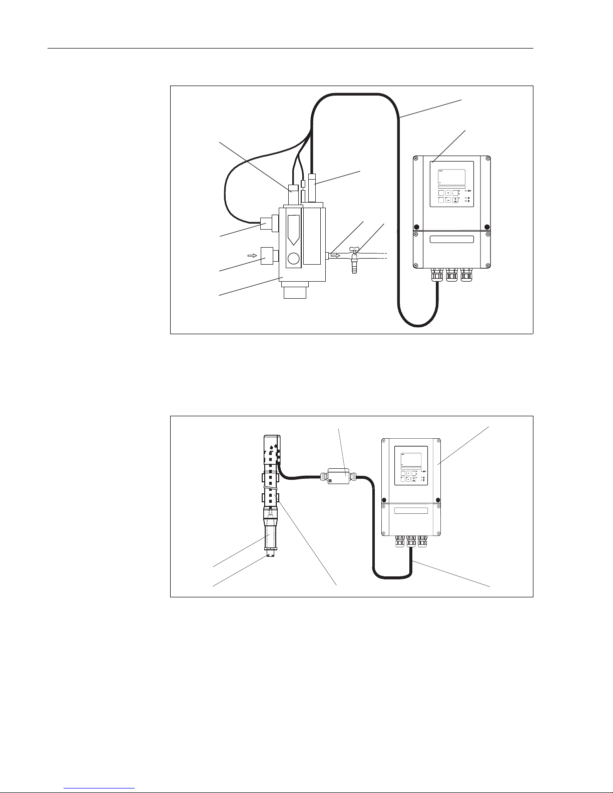
Fig. 1: Measuring system with flow assembly (example)
1 Flow assembly CCA250 6 Medium outlet
2 Medium inlet 7 Sampling tap
3 Proximity switch for flow monitoring 8 Measuring cable
4 Mounting place for pH/redox sensor 9 Transmitter
5Chlorine sensor
a0001791
Fig. 2: Measuring system with immersion assembly (example)
1 Junction box 4 Immersion assembly CYA611
2 Transmitter 5 Chlorine sensor CCS120
3 Measuring cable 6 Assembly adapter G1
CAL REL
REL1
REL1
ALARM
REL2
REL2
E
mg/l
25.0 ¡C
0.42
1
2
3
4
5
6
7
8
9
1
2
4
5
3
CAL REL
REL1
REL1
ALARM
REL2
REL2
E
mg/l
25.0 ¡C
0.42
6
Liquisys M CCM223/253 Mounting
Endress+Hauser 11
3.2 Installation conditions
3.2.1 Field instrument
a0005733
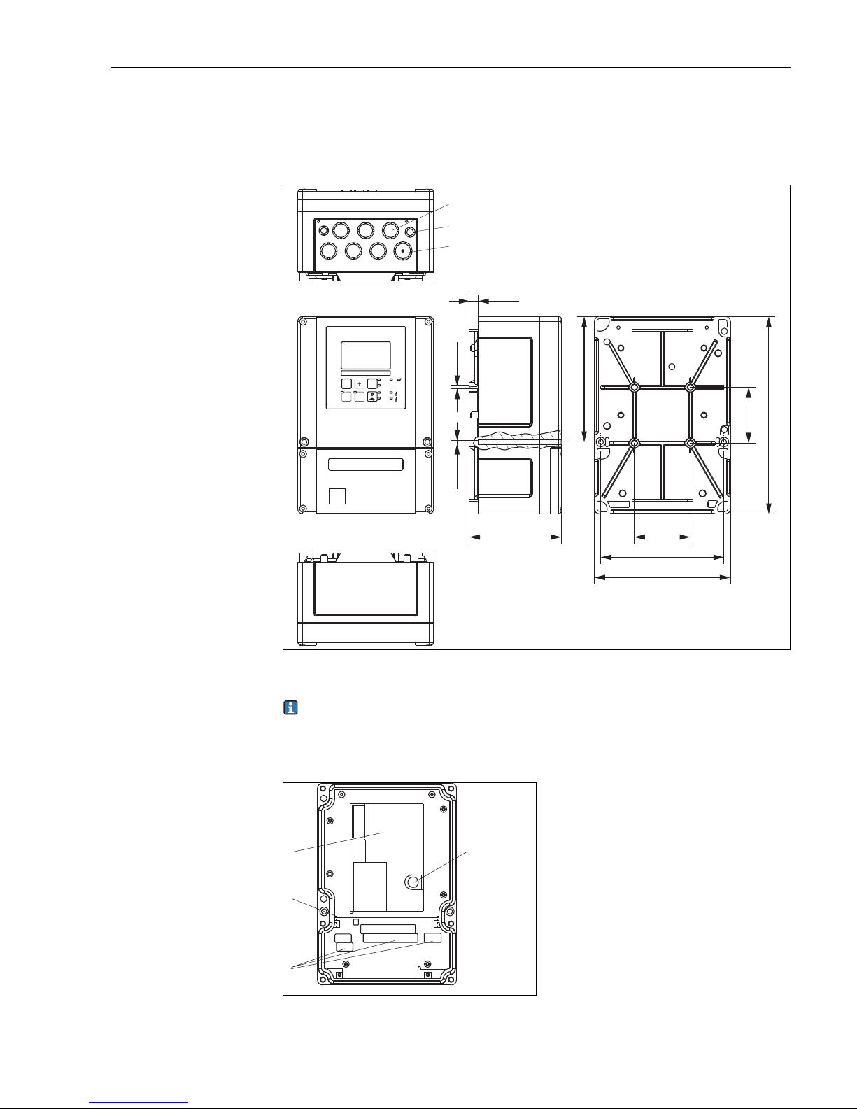
Fig. 3: Field instrument
There is a hole in the punching for the cable entry (connection of supply voltage). It
serves as a pressure balance during air freight dispatching. Make sure no moisture
penetrates the inside of the housing before the cable installation. The housing is
completely air-tight after the cable installation.
CAL REL
REL1
REL1
ALARM
REL2
REL2
E
Pg 7
Pg 16
M5
11/
0.43
Ø6/
Ø 0.24
115 / 4.53
157 / 6.18
247 / 9.72
70 / 2.76
70 / 2.76
154 / 6.06
170 / 6.69
mm / inch
Pg 13.5
a0005734
Fig. 4: View into the field housing
1
2
3
4
Removable electronics box
Partition plate
Terminals
Fuse
1
2
3
4
Mounting Liquisys M CCM223/253
12 Endress+Hauser
3.2.2 Panel-mounted instrument
a0005735
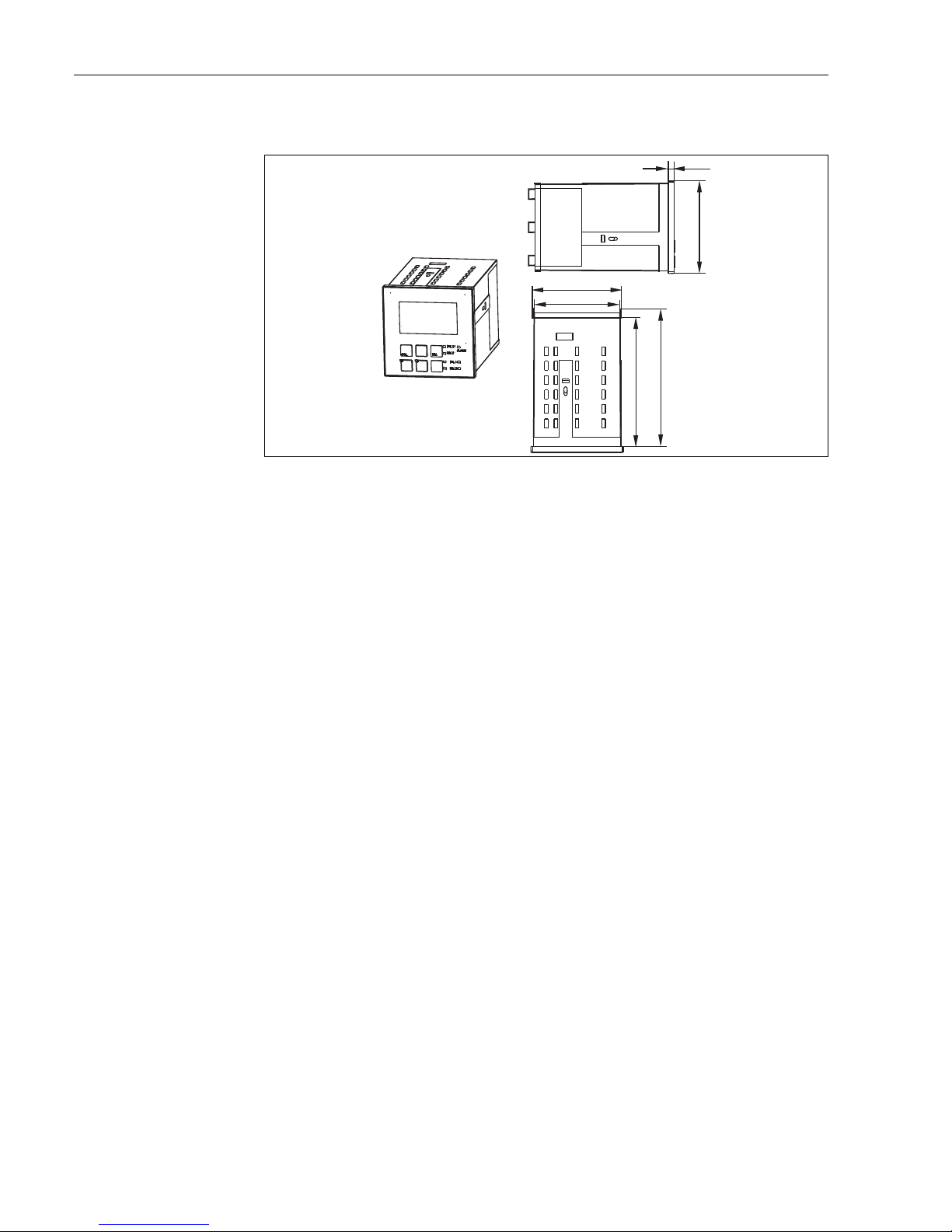
Fig. 5: Panel-mounted instrument
90 / 3.54
139 / 5.47
96 / 3.78
6/
0.24
mm / inch
92 / 3.62
149.5 / 5.89
Liquisys M CCM223/253 Mounting
Endress+Hauser 13
3.3 Installation instructions
3.3.1 Field instrument
There are several ways of securing the field housing:
• Wall mounting with fixing screws
• Post mounting to cylindrical pipes
• Post mounting to square securing masts
NOTICE
Effect of climate conditions (rain, snow, direct sun etc.)
Impaired operation to complete transmitter failure
‣ When installing outside, always use the weather protection cover (accessory).
Transmitter wall mounting
a0005736
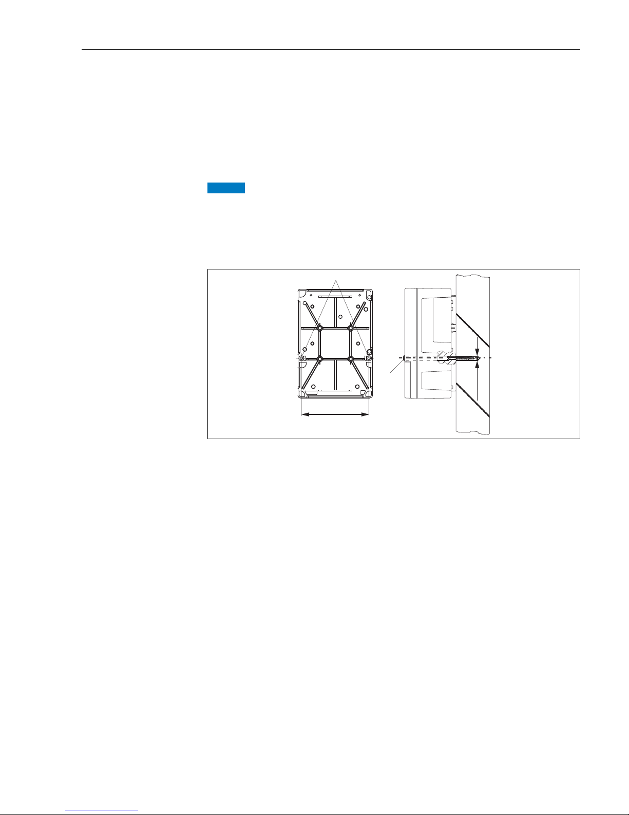
Fig. 6: Wall mounting field device
For wall mounting the transmitter, proceed as follows:
1. Drill the bores as shown in å 6.
2. Drive the two fixing screws through the securing bores (1) from the front.
3. Mount the transmitter on the wall as shown.
4. Cover the bores with plastic caps (2).
1
2
154 / 6.06
mm / inch
Ø6/
Ø 0.24
Mounting Liquisys M CCM223/253
14 Endress+Hauser
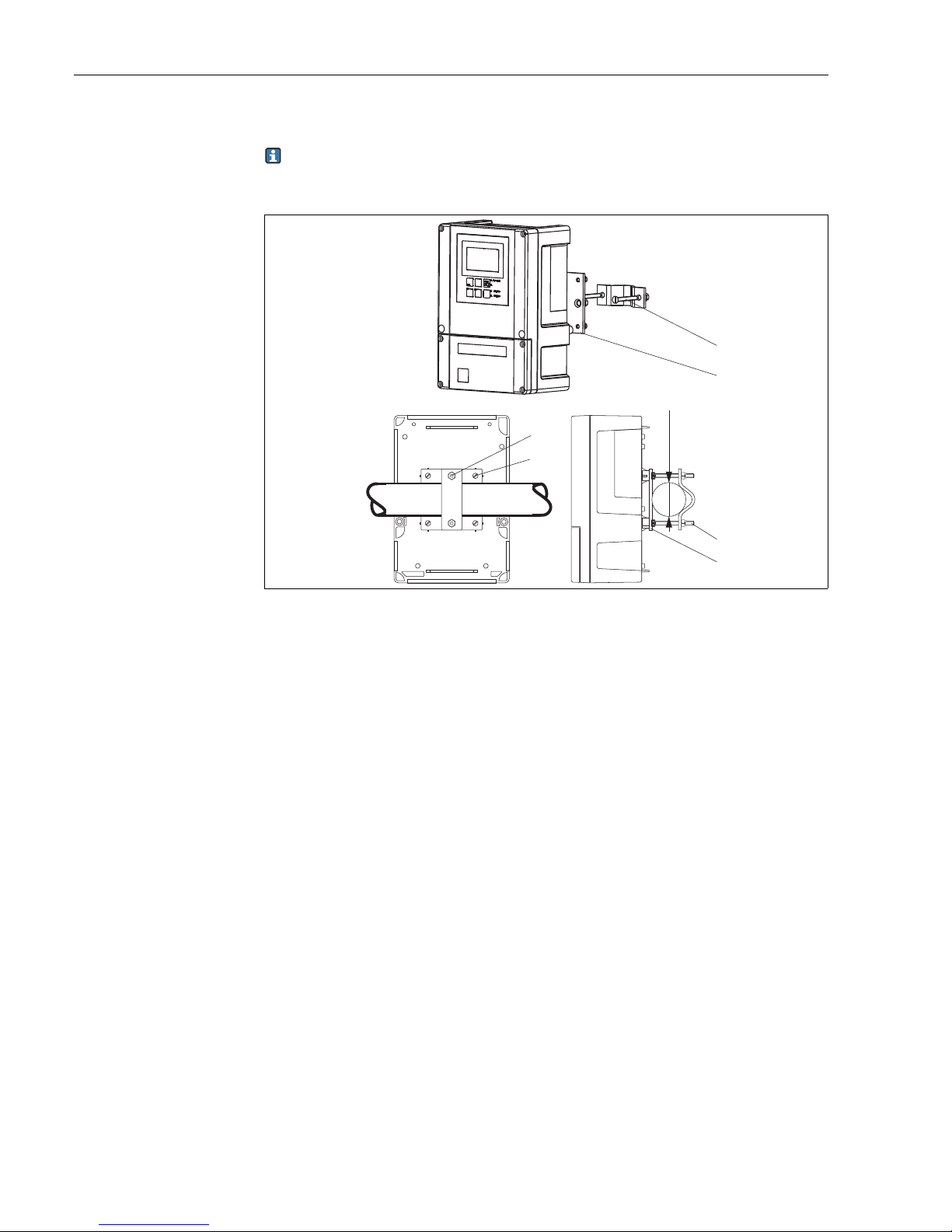
Transmitter post mounting
You require a post mounting kit to secure the field device to horizontal and vertical posts
or pipes (max. Ø 60 mm (2.36")). The kit can be acquired as an accessory (see
"Accessories" section).
a0005737
Fig. 7: Post mounting field device to cylindrical pipes
For post mounting the transmitter, proceed as follows:
1. Guide the two securing screws (1) of the mounting kit through the openings of the
securing plate (3).
2. Screw the securing plate onto the transmitter using the four fixing screws (2).
3. Secure the retainer with the field device on the post or pipe using the clip.
1
2
3
1
1
3
Ø max. 60 /
2.36
mm / inch
Liquisys M CCM223/253 Mounting
Endress+Hauser 15
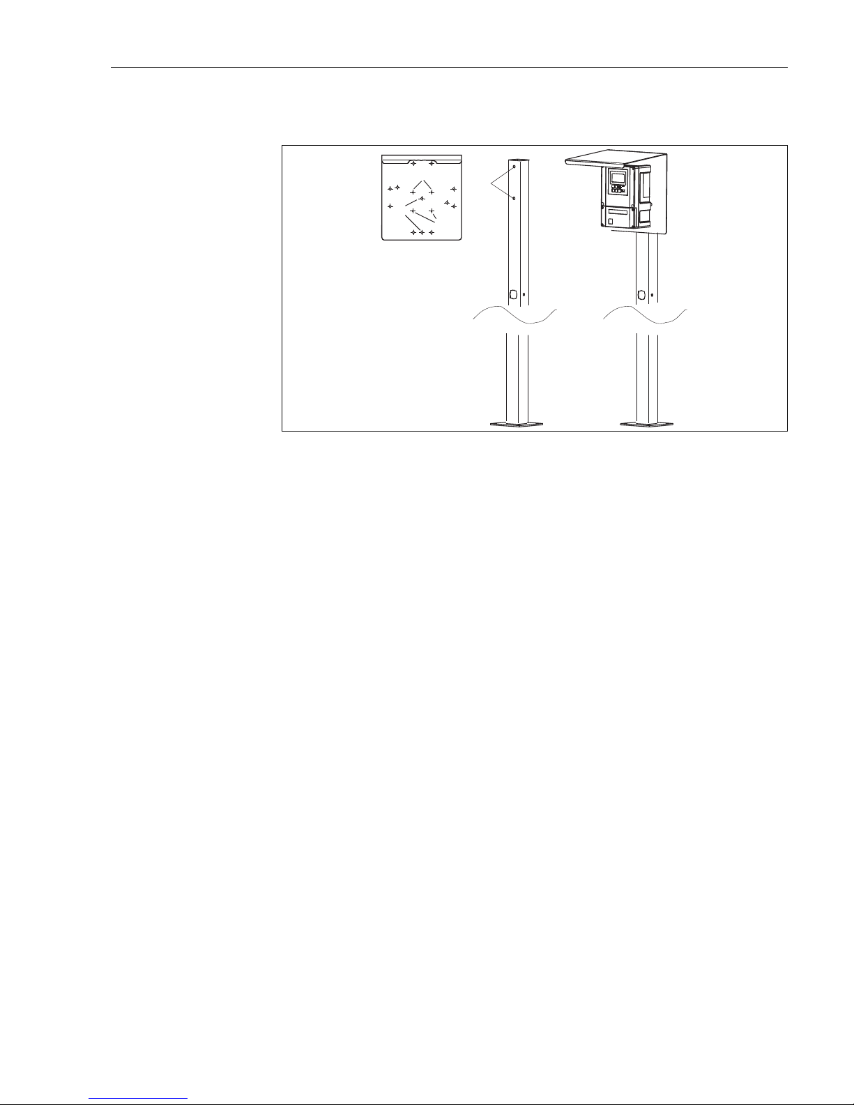
You can also secure the field device to a square universal post in conjunction with the
weather protection cover. These can be acquired as accessories, see "Accessories" section.
a0005738
Fig. 8: Mounting field device with universal posts and weather protection cover
For mounting the weather protection cover, proceed as follows:
1. Screw the weather protection cover with 2 screws (bores 1) to the upright post
(bores 2).
2. Secure the field device to the weather protection cover. To do so, use the bores (3).
3
1
2
3
Mounting Liquisys M CCM223/253
16 Endress+Hauser
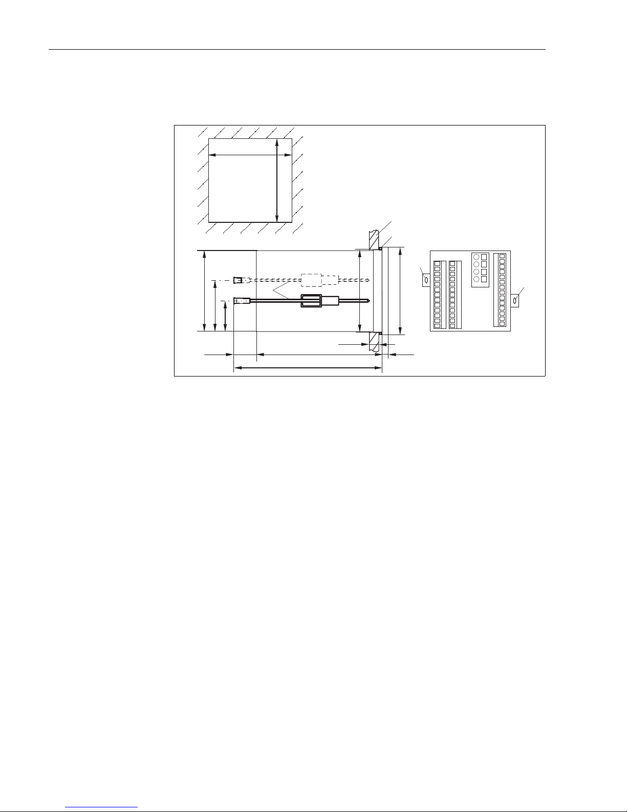
3.3.2 Panel-mounted instrument
The panel-mounted instrument is secured with the clamping screws supplied (see å 9).
The necessary installation depth is approx. 165 mm (6.50").
a0005739
Fig. 9: Securing the panel-mounted instrument
1 Wall of the cabinet
2Seal
3 Clamping screws
* Required installation depth
3.4 Post-installation check
• After installation, check the transmitter for damage.
• Check whether the transmitter is protected against moisture and direct sunlight (e.g. by
the weather protection cover).
1
2
3
3
3
92 / 3.62
+0.5 +0.02
92 / 3.62
+0.5 +0.02
90 / 3.54
57 / 2.24
33 /
1.30
approx. 25 /
0.98
139 / 5.47
max. 45 /
1.77
6 /
0.24
96 / 3.78
92 /
3.62
approx. 165 / 6.50*
mm / inch

Liquisys M CCM223/253 Electrical Connection
Endress+Hauser 17
4 Electrical Connection
WARNING
!
Device is energized
Improper connection can cause injury or death.
‣ The electrical connection must only be carried out by a certified electrician.
‣ Technical personnel must have read and understood the instructions in this manual and
must adhere to them.
‣ Prior to beginning any wir ing wor k, ma ke s ure vol tag e is n ot a ppl ied to a ny of the cab les .
The electrical connection of the transmitter differs depending on the sensor:
• If you are using the membrane-covered sensor CCS140 / 141 / 240 / 241 or the open
sensor 963, please read the instructions in the "Electrical connection version 1" section.
• If you are using the total chlorine sensor CCS120, please read the instructions in the
"Electrical connection version 2" section.
4.1 Wiring
4.1.1 Connecting supply voltage
NOTICE
The device does not have a power switch
‣ You must provide a protected circuit breaker in the vicinity of the device.
‣ This must be a switch or a power-circuit breaker and you must label it as the circuit
breaker for the device.
‣ At the supply point, the power supply for the 24 V versions must be isolated from
dangerous live cables by double or reinforced insulation.
Electrical Connection Liquisys M CCM223/253
18 Endress+Hauser
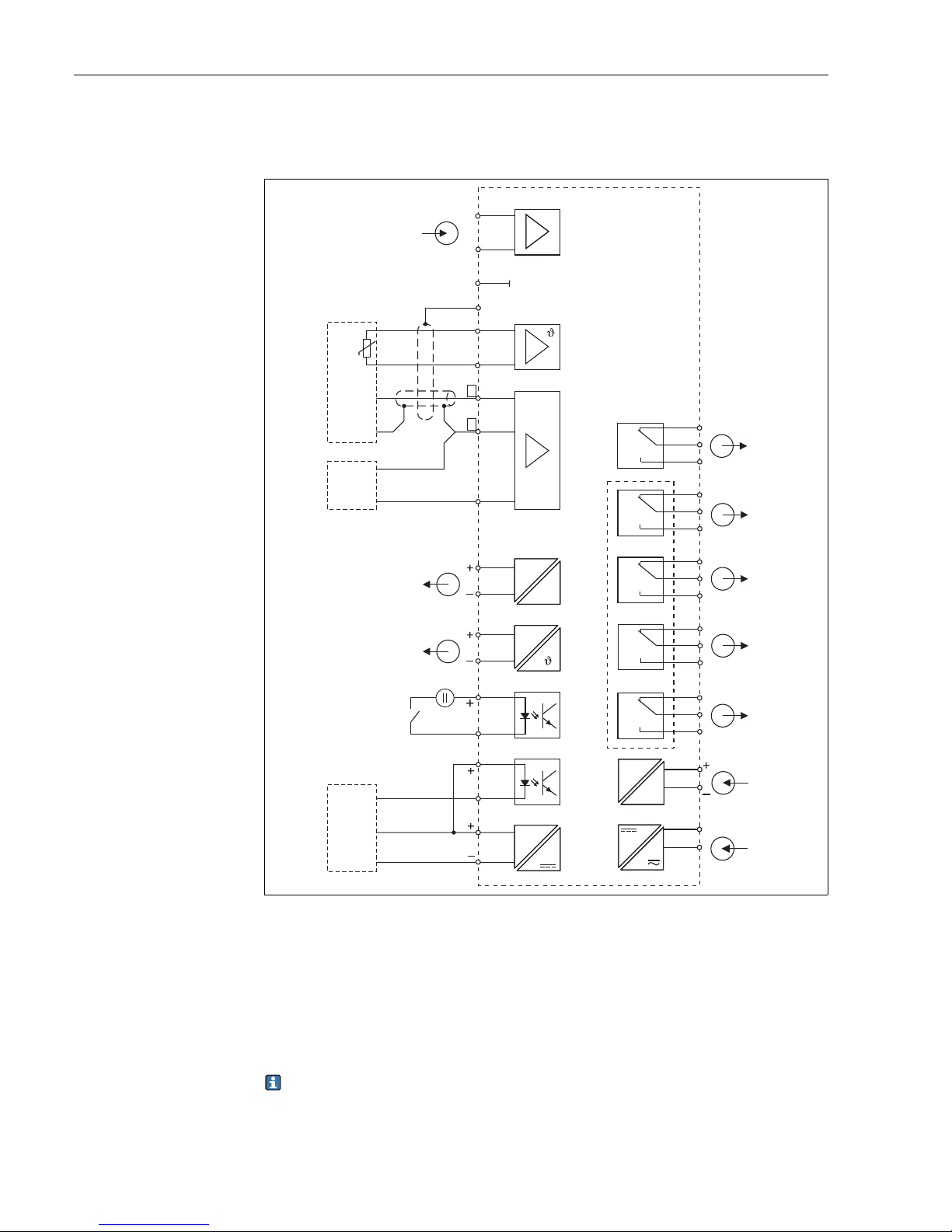
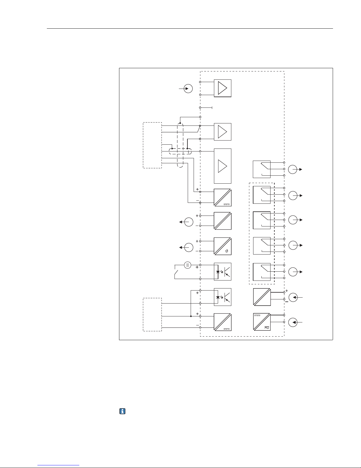
4.1.2 Electrical connection version 1
The wiring diagram shows the connections of the transmitter with all options
The device is approved for protection class II and is generally operated without
protective ground connection.
The circuits "E" and "I" are not galvanically separated from each other.
a0001903
Fig. 10: Electrical connection of the transmitter (version 1)
A
B
C
D
E
F
G
H
*
pH / ORP input (optional)
Sensor CCS140/141/240/241
Sensor 963 (alternative)
Signal output 1 chlorine / chlorine dioxide
Signal output 2 temperature, pH or ORP
Binary input 1 (hold / cleaning)
Proximity switch INS
Binary input 2
Aux. voltage output terminal 85/86 applicable
I
J
K
L
M
N
O
P
Aux. voltage output
Alarm (current-free contact position)
Relay 1 (current-free contact position)
Relay 2 (current-free contact position)
Relay 3 (current-free contact position)
Relay 4 (current-free contact position)
Current input 4 to 20 mA
Power supply
15 V
85
86
81
93
82
94
mA
31
32
mA
mA
33
34
54
55
56
23
24
90
12
11
91
92
S
ClO
2
ClO
2
Cl
2
Cl
2
K
A
A
K
K
A
NTC
pH
Red.
Ref.
PA/
PM
10–50 V
41
42
43
47
48
49
57
58
59
51
52
53
L+
L–N
L1
~=
pH/
Redox
GN
BN
RD
BU
RD
BK
BN
BU
A
B
C
D
E
F
G
H
I
J
K
L
M
N
O
P
*
Liquisys M CCM223/253 Electrical Connection
Endress+Hauser 19
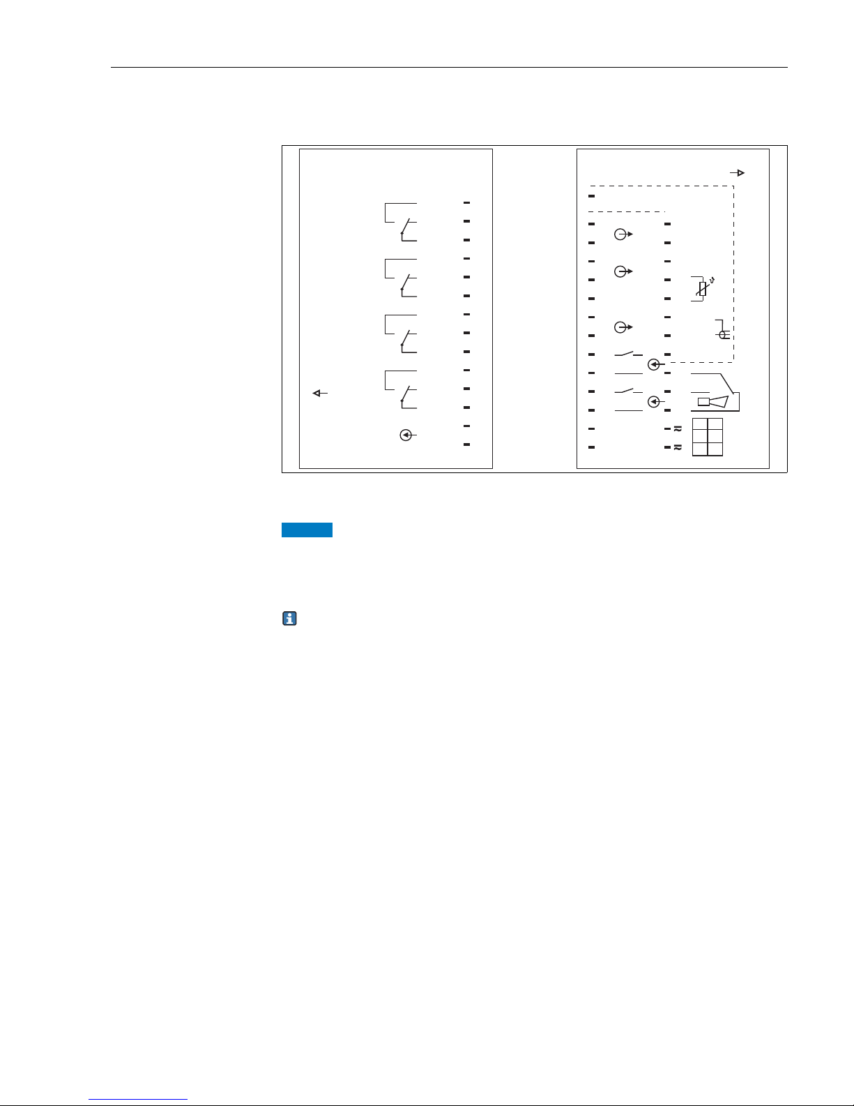
4.1.3 Electrical connection version 2
The wiring diagram shows the connections of the transmitter with all options
The device is approved for protection class II and is generally operated without
protective ground connection.
The circuits "E" and "C" are not galvanically separated from each other.
a0001904
Fig. 11: Electrical connection of the transmitter (version 2)
A
B
C
D
E
F
G
H
*
pH / ORP input (optional)
Sensor CCS120
Aux. voltage output
Signal output 1 total chlorine
Signal output 2 temperature, pH or ORP
Binary input 1 (hold / cleaning)
Proximity switch INS
Binary input 2
Aux. voltage output terminal 85/86 applicable
J
K
L
M
N
O
P
Alarm (current-free contact position)
Relay 1 (current-free contact position)
Relay 2 (current-free contact position)
Relay 3 (current-free contact position)
Relay 4 (current-free contact position)
Current input 4 to 20 mA
Power supply
15 V
85
86
81
93
82
94
mA
31
32
mA
mA
33
34
54
55
56
23
24
90
12
11
S
ClO
2
ClO
2
Cl
2
Cl
2
pH
Red.
Ref.
PA/
PM
10–50 V
41
42
43
47
48
49
57
58
59
51
52
53
L+
L–N
L1
~=
pH/
Redox
YE
BK
BK
BN
BU
A
B
C
D
E
F
G
H
J
K
L
M
N
O
P
15 V
85
86
CCS
120
WH
GN
BN
C
*

Electrical Connection Liquisys M CCM223/253
20 Endress+Hauser
4.1.4 Device connection
Field instrument connection
Proceed as follows to connect the field instrument:
1. Open the housing cover to access the terminal block in the connection compartment.
2. Break the punching of a cable gland from the housing, mount a cable gland and guide
the cable through this cable gland.
3. Connect the cable in accordance with the terminal assignment ( å 12).
4. Tighten the cable gland.
NOTICE
Nonobservance could cause incorrect measurement
‣ Make sure to protect the connectors, cable ends and terminals against moisture.
‣ Terminals marked NC may not be wired.
‣ Unmarked terminals may not be wired.
a0002276
Fig. 12: Field instrument connection compartment sticker
Please label the sensor terminal block with the sticker provided.
pH / Redox
42
+
+
++++-
-
----
434154 55 56
NC
91
90
31
11
12
32
92
PA/ PM
3433
S
REF
NC 938685 94 812382
24
NC
51 52 53 57 58 59 47 48 49
Cl
ClO
2
(963:92/K)
2
Temp.
pH/Redox
(opt.)
+15V
10mA
BN
(RD)GN(BU)
BN
REL 4SENSOR REL 3 REL 2 REL 1
131194-4D
CCM 253
Digital 2
(INS)
Digital 1
4..20mA
1191/A
1290/K
NC
Mains
Hilfsenergie
L1+N
-
(AC)
(DC)
Contacts:
max. 2A
AC: 250V/500VA
DC: 30V/60W
Liquisys M CCM223/253 Electrical Connection
Endress+Hauser 21
Panel-mounted instrument connection
Connect the cable in accordance with the terminal assignment ( å 13)
a0002277
Fig. 13: Panel-mounted instrument connection sticker
NOTICE
Nonobservance could cause incorrect measurement
‣ Make sure to protect the connectors, cable ends and terminals against moisture.
‣ Terminals marked NC may not be wired.
‣ Unmarked terminals may not be wired.
Please label the sensor terminal block with the sticker provided.
REL1
REL2
REL3
REL4
4..20mA
24
23
49
COM
COM
COM
COM
-
+
59
54
55
56
52
51
53
58
57
48
47
131084-4C
31 +
32 -
33 +
PA/ PM
34 -
85 +
NC
91
90
NC
(REF)
Sensor
NC
86 -
93 + S
94 - 42
81 + 43
82 - 41
Cl
2
Tem p.
pH
Redox
(opt.)
+15V
10mA
Digital 2
(INS)
Digital 1
92
12
11
K
A
BN
BN
GN
131192-4C
K
ClO
2
963
CCS..
963
BNC: pH/Redox + REF
RD
BU
Mains
Contacts: max. 2A, AC:250V/500VA, DC:30V/60W
L1 +
AC DC
N-
Electrical Connection Liquisys M CCM223/253
22 Endress+Hauser
4.1.5 Measuring cable and sensor connection
Connection of the sensors CCS140 / 141 / 240 /241
The sensors are equipped with a 3 m (9.8 ft) fixed cable. Connect the sensor to the
transmitter as follows:
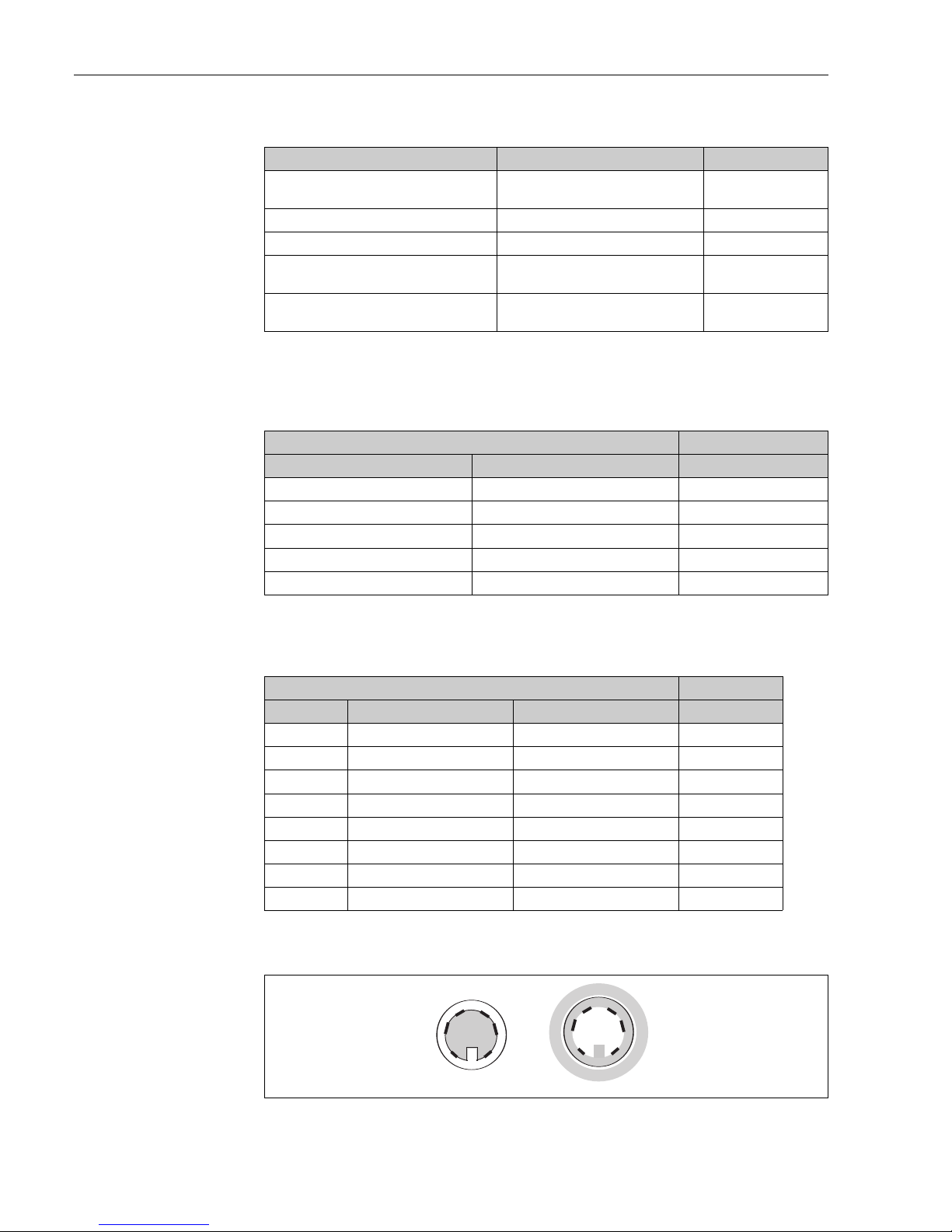
Connection of the total chlorine sensor CCS120
Connect the sensor with the measuring cable l CPK9-N*A1B (with internal PML) as follows:
* The white and the yellow wire are interconnected inside of the TOP68 plug.
a0001689
Fig. 14: TOP68 plug connection; pin assignment of plug, male and female (shown from contact side)
Type of sensor Cable Extension
Chlorine / chlorine dioxide sensors
CCS140 / 141 / 240 / 241
3 m (9.8 ft) CMK, fixed cable VBC junction box +
CMK
Chlorine sensor 963 – VBC junction box + MK
Temperature sensor for sensor 963 CPK1
Total chlorine sensor CCS120 CPK9-N*A1B VBC junction box +
CYK71
pH or ORP sensor without temperature
sensor
CPK1 for sensors with GSA plug-in head
CPK9 for sensors with ESA plug-in head
VBC junction box +
CYK71
Sensor with 3 m (9.8 ft) fixed cable Transmitter
Pin assignment Wire Terminal
Outer screen S
Anode [A] red 91
Cathode [K] 90
NTC temperature sensor green 11
NTC temperature sensor brown 12
Cable with TOP68 plug connection Transmitter
Pin Assignment Wire Terminal
1 TC signal coax inside (white) 90
2 AGND coax outside(black) 12
3
4 +UB (15 V) green 85
5NTC1 yellow* 11
NTC1 white* 11
6NTC2/AGND brown 86
S screen S S
1
2
3
5
6
4
1
2
3
5
6
4

Liquisys M CCM223/253 Electrical Connection
Endress+Hauser 23
Connection of the sensors 963
The sensor 963 is supplied without temperature sensor ex factory. Connect the sensor to the
transmitter as follows:
• Without temperature measurement:
Connect the supplied resistor10 k to the terminals 11 and 12. The measured value
display will constantly indicate 25 °C (77 °F).
• With temperature measurement:
Install the NTC temperature sensor10 k / 25 °C (77 °F) (120 mm installation version TSP
3692) into the sensor 963. Use the measuring cable CPK1 to connect the temperature
sensor to the terminals 11 and 12 of the transmitter.
• Chlorine sensor:
Connect the red wire to terminal 92 (cathode) and the blue wire to the terminal 91
(anode).
Connection of pH or ORP sensors
Connect the pH or ORP sensor always symmetrically to prevent a mutual interference of
several sensors mounted in the CCA250 assembly.
Symmetrical connection requires a potential matching pin. It is integrated as standard in the
CCA250 flow assembly and is connected to the PA/PM terminal by a potential matching
line.
a0002330-en
Fig. 15: Connection of the pH or ORP sensor to the field instrument with the cables CPK1 or CPK9
CPK1
CPK9
PM
pH / Redox
PM
pH + Pt 100 / Pt 1000
Coax Ref.
pH or Redox
BN PM
Coax BK Ref.
inner pH
GN Temp.
WH Temp.
YE Temp.
BN PM
Electrical Connection Liquisys M CCM223/253
24 Endress+Hauser
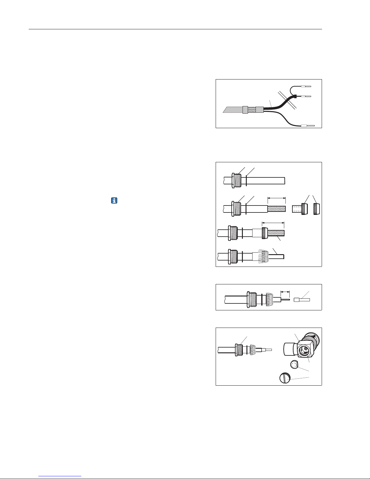
If you are using glass electrodes with the panel-mounted instrument, you have to terminate
the measuring cable with a BNC connector. A solder-free BNC connector is supplied with the
device.
Proceed as follows:
1. Cut off end sleeves 2 and 3 of the coaxial
cable ( å 16).
a0005744
Fig. 16: Cable CPK1: device connection
1Coaxial cable
2 Inner screen BK (ref.)
3 Inner coax (pH/mV)
4Strand BN (PA)
2. Push the cable gland 5 and the washer 6
onto the coaxial cable.
3. Remove the insulation (13 mm(0.51"))
and screw the clamping ring 7 onto the
insulation.
Parts 5 to 7 are supplied with the BNC
connector for cable diameters 3.2 mm
(0.13") and 5 mm (0.20").
4. Fold the braided screen 8 over the
clamping ring and cut off the excess
material.
5. There is a semi-conductor layer 14
(conductive foil) between the inner
insulation and the braided screen 8. Strip
this semi-conductor layer to the braided
screen.
a0005745
Fig. 17: Terminating the pH connecting cable for mounting
the BNC elbow plug
6. Remove the inner insulation (4 mm
(0.16")).
7. Position the end sleeve 13 onto the
stripped inner conductor and secure the
end sleeve with crimping pliers.
a0005746
Fig. 18: Terminating the pH connecting cable for mounting
the BNC elbow plug
8. Push the BNC connector housing 9 over
the cable. The inner conductor must be
located on the clamping surface 10 of the
connector.
9. Tighten the cable gland 5.
10.Insert the clamp element 11 and screw in
the connector cover 12. This creates a safe
connection between the inner conductor
and the connector pin.
a0005747
Fig. 19: Mounting the pH connecting cable in the BNC elbow
plug
3
4
1
2
56
56
7
8
14
13 / 0.51
16 / 0.63
mm / inch
13
4/
0.16
mm / inch
5
9
10
11
12

Liquisys M CCM223/253 Electrical Connection
Endress+Hauser 25
Cable extension
To extend the measuring cable use the junction box VBC and the corresponding extension
cable.
a0005740
Fig. 20: VBC junction box with grounding point
A View in arrow direction
B 2 fixing holes Ø 4.5 mm / 0.18 "
NOTICE
Incorrect measurement due to short-circuit
‣ Make sure to remove the black semiconductor layer up to the inner screen when
performing termination work!
Maximum cable lengths
Sensors CCS140/141/240/241 max. 30 m (98.4 ft) with cable CMK
Chlorine sensor 963 max. 30 m (98.4 ft) with cable MK
Total chlorine sensor CCS120 max. 15 m (49.2 ft) with cable CYK71
pH or ORP measurement max. 50 m (164 ft) with cable CYK71
2xPg7
2xPg11
5xPg7
A
B
B
mm / inch
54 / 2.13
113 / 4.45
125 / 4.92
52 / 2.05
a0002331
Fig. 21: CMK cable
1 Outer screen
2 Inner screen, anode
3 Semiconductor layer
4 Inner insulation
5 Inner conductor, measuring signal
6 Temperature sensor connection
7 2nd insulation
8 Outer insulation
a0002332
Fig. 22: CYK71 cable
1 Outer screen
2 Inner screen, reference signal
3 Inner insulation
4 Inner conductor, measuring signal
5 Semiconductor layer
6 2nd insulation
7 Outer insulation
BN
GN
1
2
3
4
5
6
7
8
1
23
45
6
7
Electrical Connection Liquisys M CCM223/253
26 Endress+Hauser
4.1.6 Three-point step controller for Cl2 / ClO2 / total chlorine
Connect the continuously variable motor valves as follows:
• Connect the "closing" contact of the motor valve to relay 3.
• Connect the "opening" contact of the motor valve to relay 4.
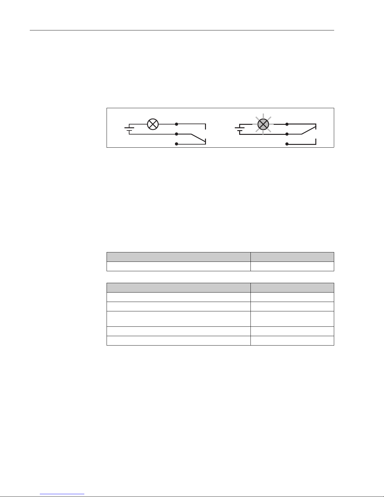
4.1.7 Alarm contact
4.2 Post-connection check
After the electrical connection, carry out the following checks:
a0006415
Fig. 23: Recommended fail-safe switching for the alarm contact
A Normal operating status B Alarm condition
Normal operating status:
Device in operation and no error message
present (alarm LED off)
• Relay energized
• Contact 42/43 closed
Alarm condition
Error message present (alarm LED red) or
device defective or voltage-free (alarm LED off)
• Relay de-energized
• Contact 41/42 closed
Device condition and specifications Notes
Are the transmitter and cables damaged on the outside? Visual inspection
Electrical connection Notes
Are the mounted cables strain relieved?
Cable run without loops and cross-overs?
Are the signal lines correctly connected in accordance with the wiring
diagram?
Are all screw terminals tightened?
Are all cable entries installed, tightened and sealed?
41
42
43
41
42
43
A
B

Liquisys M CCM223/253 Operability
Endress+Hauser 27
5Operability
5.1 Quick operation guide
You have the following ways of operating the transmitter:
• On site via the key field
• Via the HART interface (optional, with corresponding order version) per:
– HART handheld terminal or
– PC with HART modem and the FieldCare software package
• Via PROFIBUS PA/DP (optional, with corresponding order version) with:
PC with corresponding interface and the FieldCare software package (see Accessories) or
via a programmable logic controller (PLC)
For operation via HART or PROFIBUS PA/DP, please read the relevant sections in the
additional Operating Instructions:
•PROFIBUS PA/DP, field communication for Liquisys M CXM223/253,
BA00209C/07/EN
•HART, field communication for Liquisys M CXM223/253, BA00208C/07/EN
The following section only explains operation via the keys.
5.2 Display and operating elements
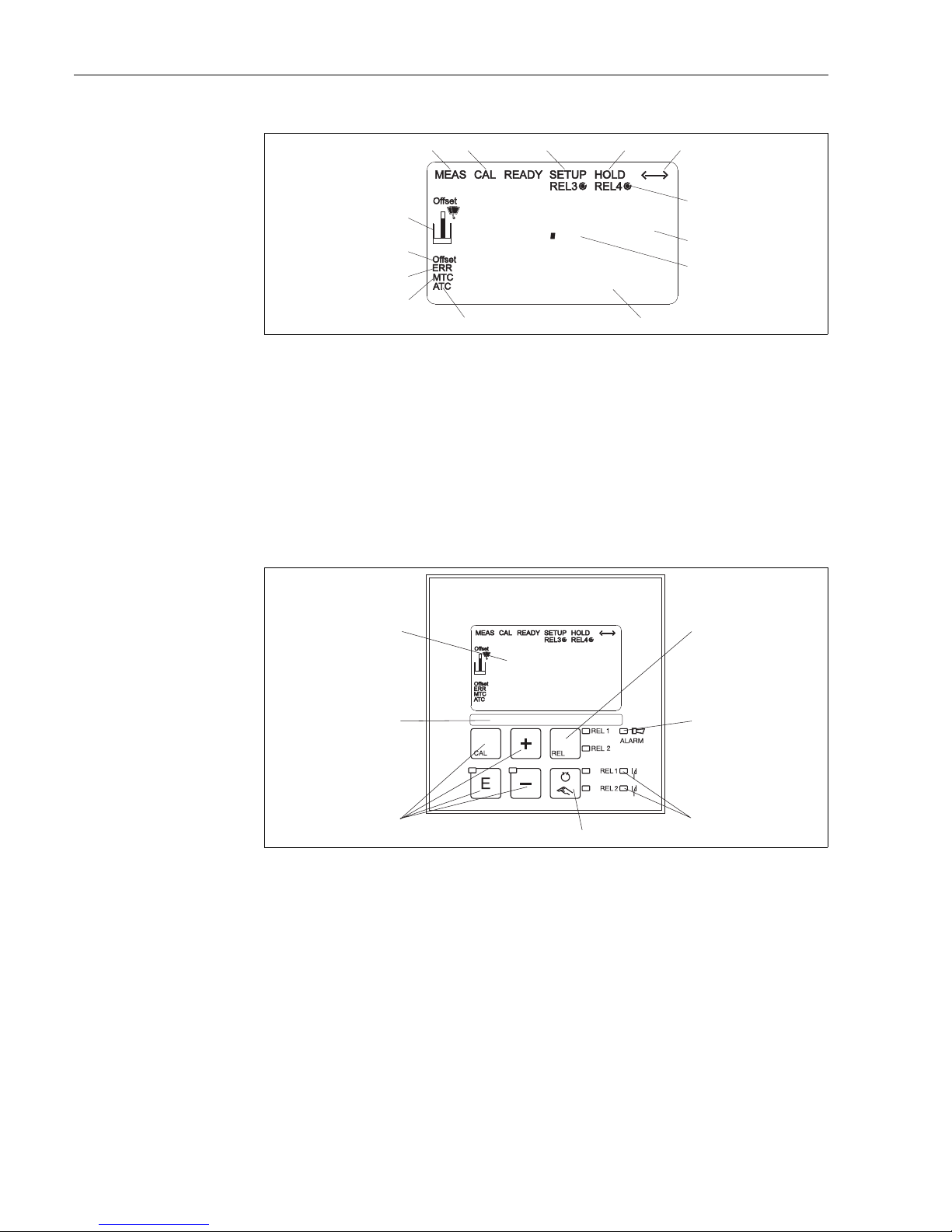
5.2.1 Display
LED display
Indicates the current operating mode, "Auto" (green LED) or
"Manual" (yellow LED)
Indicates the activated relay in the "Manual" mode (red LED)
Indicates the working status of relay 1 and 2
LED green: measured value within the permitted limit, relay
inactive
LED red: measured value outside the permitted limit, relay active
Alarm display, e.g. for continuous limit value overshoot,
temperature sensor failure or system error (see error list)
REL 1
REL 2
Operability Liquisys M CCM223/253
28 Endress+Hauser
LC display
5.2.2 Operating elements
a0001925-en
Fig. 25: Operating elements
1 LC display for displaying the measured values and configuration data
2 Field for user labelling
3 4 main operating keys for calibration and device configuration
4 Changeover switch for automatic/manual mode of the relays
5 LEDs for limit contactor relay (switch status)
6 LED for alarm function
7 Display of the active contact and key for relay changeover in manual mode
a0001924-en
Fig. 24: Liquid crystal display
1
2
3
4
5
6
7
Indicator for measuring mode (normal operation)
Indicator for calibration mode
Indicator for setup mode (configuration)
Indicator for "Hold" mode (current outputs remain
at last current state)
Indicator for receipt of a message for devices with
communication
Indicator of working status of relays 3/4:
d
inactive, cactive
Function code display
8
9
10
11
12
13
14
In measuring mode: measured variable
In setup mode: configured variable
In measuring mode: secondary measured value
In setup/calibr. mode: e.g. setting value
Indicator for autom. temperature compensation
Indicator for man. temperature compensation
"Error": error display
Temperature offset
Sensor symbol
mg/l
R242
1
23
4
5
6
7
8
9
12
13
14
042
10
11
Setpoint
0.42
mg/l
R242
1
2
3
4
5
6
7
Setpoint
Liquisys M CCM223/253 Operability
Endress+Hauser 29
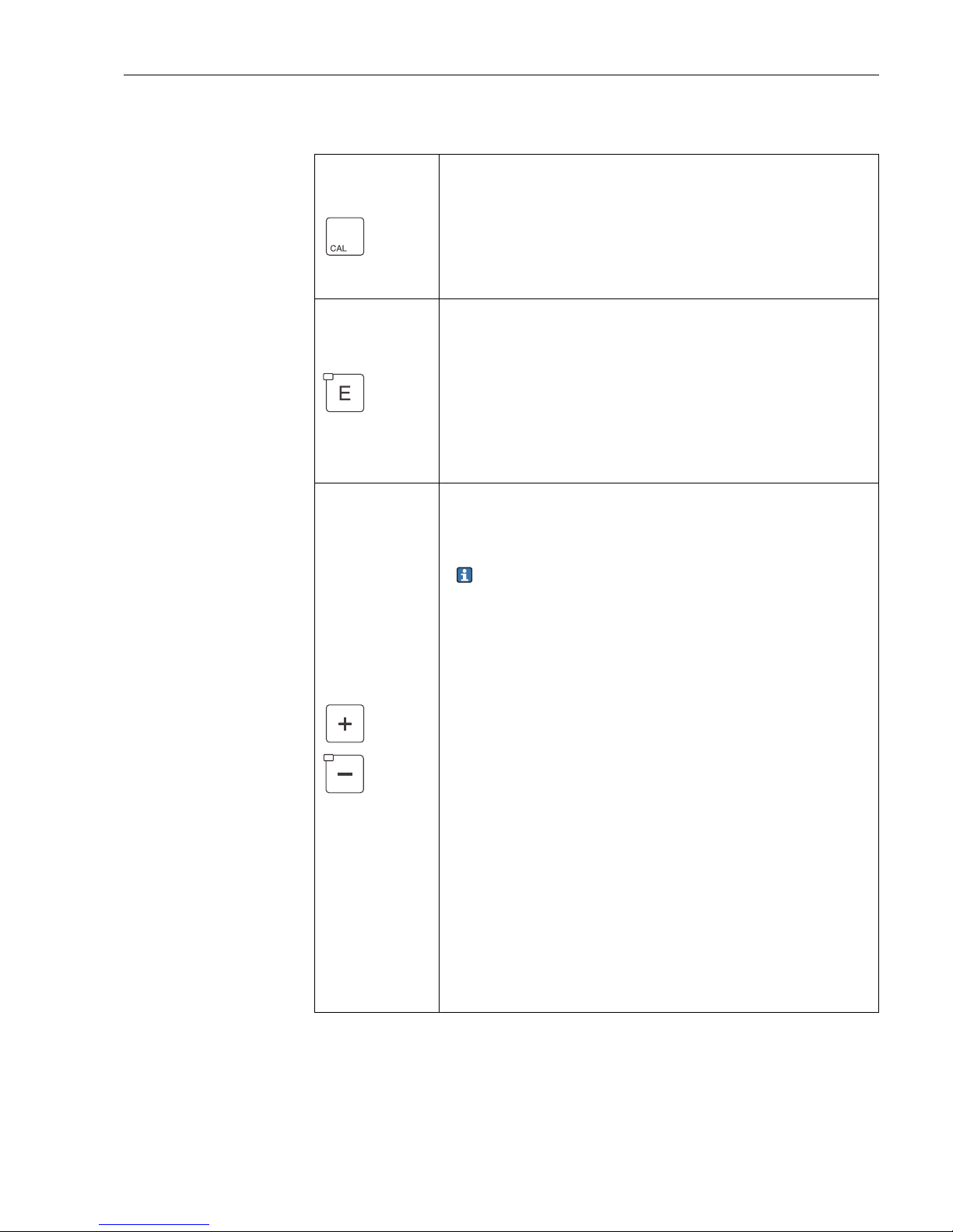
5.2.3 Key assignment
CAL key
When you press the CAL key, the device first prompts you for the
calibration access code:
• Code 22 for calibration
• Code 0 or any other code for reading the last calibration data
Use the CAL key to accept the calibration data or to switch from field
to field within the calibration menu.
ENTER key
When you press the ENTER key, the device first prompts you for the
setup access code:
• Code 22 for setup and configuration
• Code 0 or any other code for reading all configuration data.
The ENTER key has several functions:
• Calls up the Setup menu from the measuring mode.
• Saves (confirms) data entered in the setup mode.
• Moves on within function groups.
PLUS key and MINUS key
In setup mode, the PLUS and MINUS keys have the following
functions:
• Selection of function groups.
Press the MINUS key to select the function groups in the order
given in the "System configuration" section.
• Configuration of parameters and numerical values
• Operation of the relay in manual mode
In measuring mode, you get the following sequence of functions by
repeatedly pressing the PLUS key:
1. Temperature display in °F
2. Temperature display hidden
3. pH measuring value or ORP potential (only on EP version)
4. pH sensor signal in mV (only on EP version)
5. Measured value display of Cl
2
/ ClO2 in nA
6. Zero current of the sensor CCS120
7. Measured value display of current input in %
8. Measured value display of current input in mA
9. Return to basic settings
In measuring mode, the following is displayed in sequence by
repeatedly pressing the MINUS key:
1. Current errors are displayed in rotation (max. 10).
2. Once all errors have been displayed, the standard measurement
display appears. In the function group F, an alarm can be defined
separately for each error code.
Operability Liquisys M CCM223/253
30 Endress+Hauser
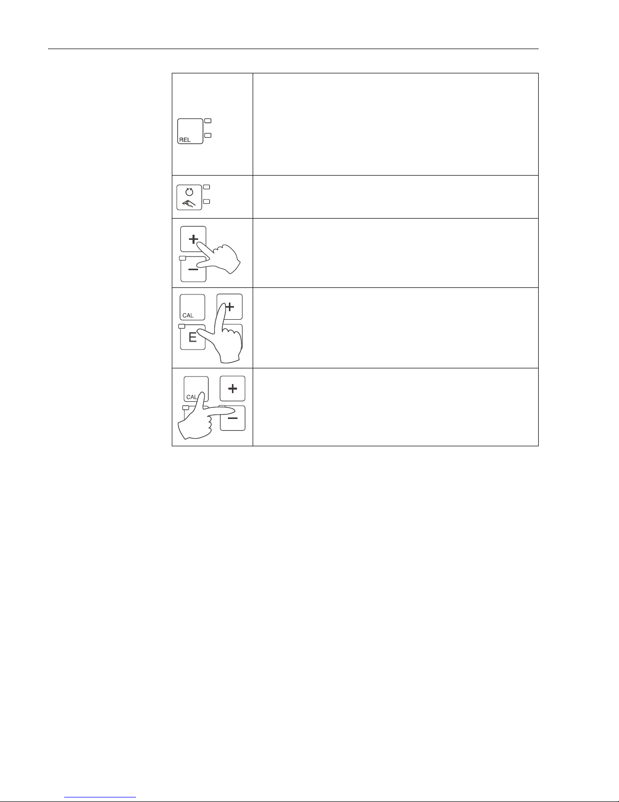
REL key
In manual mode, you can use the REL key to switch between the relay
and the manual start of cleaning.
In automatic mode, you can use the REL key to read out the switch-on
points (for limit contactor) or set points (for PID controller) assigned
to the relay in question.
Press the PLUS key to jump to the settings of the next relay. Use the
REL key to get back to the display mode (automatic return after 30 s).
AUTO key
You can use the AUTO key to switch between automatic mode and
manual mode.
Escape function
If you press the PLUS and MINUS key simultaneously, you return to
the main menu or are taken to the end of calibration if calibrating. If
you press the PLUS and MINUS key again, you return to the
measuring mode.
Locking the keyboard
Press the PLUS and ENTER key for at least 3 s to lock the keyboard
against any unauthorized data entry. All the settings can continue to
be read.
The code prompt displays the code 9999.
Unlocking the keyboard
Press the CAL and MINUS key for at least 3 s to unlock the keyboard.
The code prompt displays the code 0.
REL 1
REL 2
 Loading...