

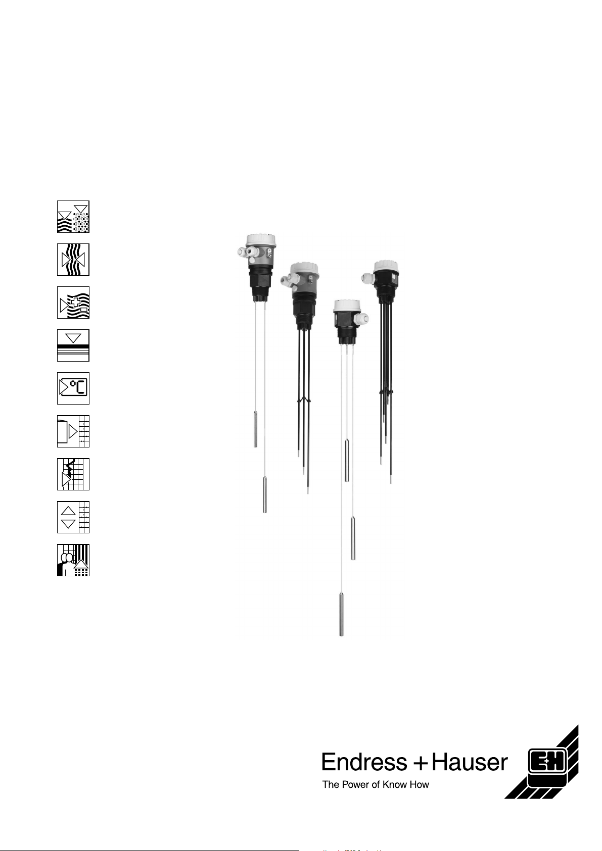
Endress+Hauser Liquipoint T Series, Liquipoint T FTW 32, Liquipoint FTW 31 Technical Information
Page 1
Technical Information
TI 375F/00/en
Level Limit Detection in Liquids
liquipoint T FTW 31, FTW 32
Level limit switch for multiple point detection
in conductive liquids
Applications
Liquipoint T sensors are used in
conductive liquids (as of 10 µS/cm) for
determining level limits.
Depending on the number of measuring
points (up to 5 rods or ropes), measuring
tasks such as overspill protection, dry
running protection, two-point control of
pumps or multiple point detection can be
implemented for an existing process
connection.
Your benefits
•
Detect up to five level limits with one
probe
•
Two-point control and additional
maximum and minimum detection
•
Option between rod or rope version for
optimum adaptation to the application
•
Flexible instrumentation:
– with built-in electronic insert, either
transistor or relay output for 2 or
3 rod/rope probes
– for connection to a separate
transmitter power supply unit
•
No calibration required;
standard setting for the most common
conductive liquids
•
No moving parts in the tank:
– long service life
– reliable operation with no wear or
blockages
•
WHG approval
•
Four measuring ranges can be set
100 Ω, 1 kΩ, 10 kΩ, 100 kΩ
•
Cost-effective probe for conductive
liquids
•
Electronic inserts for:
– NAMUR output
– Relais output
– Transistor output
Page 2

Table of contents
Liquipoint T FTW 31, FTW 32
Function and system design . . . . . . . . . . . . . . . . . . 3
Measuring principle . . . . . . . . . . . . . . . . . . . . . . . . . . . . . . 3
Measuring system . . . . . . . . . . . . . . . . . . . . . . . . . . . . . . . . 3
Input . . . . . . . . . . . . . . . . . . . . . . . . . . . . . . . . . . . . . . 5
Measured variable . . . . . . . . . . . . . . . . . . . . . . . . . . . . . . . 5
Measuring range (application) . . . . . . . . . . . . . . . . . . . . . . 5
Input signal . . . . . . . . . . . . . . . . . . . . . . . . . . . . . . . . . . . . . 5
Output. . . . . . . . . . . . . . . . . . . . . . . . . . . . . . . . . . . . . 5
Electronic insert FEW 52 (DC-PNP) . . . . . . . . . . . . . . . . . . 5
Electronic insert FEW 54 (relay) . . . . . . . . . . . . . . . . . . . . . 6
Electronic insert FEW 58 (NAMUR) . . . . . . . . . . . . . . . . . . . 8
Cable monitoring . . . . . . . . . . . . . . . . . . . . . . . . . . . . . . . . . 8
Power supply. . . . . . . . . . . . . . . . . . . . . . . . . . . . . . . 9
Electrical connection (wiring diagrams) . . . . . . . . . . . . . . . 9
Cable entry . . . . . . . . . . . . . . . . . . . . . . . . . . . . . . . . . . . . 13
Cable specifications . . . . . . . . . . . . . . . . . . . . . . . . . . . . . 13
Accuracy with built-in electronic insert . . . . . . . . 14
Reference operating conditions . . . . . . . . . . . . . . . . . . . . 14
Measuring error . . . . . . . . . . . . . . . . . . . . . . . . . . . . . . . . . 14
Repeatability . . . . . . . . . . . . . . . . . . . . . . . . . . . . . . . . . . . 14
Hysteresis . . . . . . . . . . . . . . . . . . . . . . . . . . . . . . . . . . . . . 14
Switch-on delay . . . . . . . . . . . . . . . . . . . . . . . . . . . . . . . . 14
Influence of ambient temperature . . . . . . . . . . . . . . . . . . . 14
Certificates and approvals . . . . . . . . . . . . . . . . . . . 23
CE mark . . . . . . . . . . . . . . . . . . . . . . . . . . . . . . . . . . . . . . 23
Overspill protection . . . . . . . . . . . . . . . . . . . . . . . . . . . . . 23
Other standards and guidelines . . . . . . . . . . . . . . . . . . . . 23
Ex-approvals . . . . . . . . . . . . . . . . . . . . . . . . . . . . . . . . . . 23
Type of protection . . . . . . . . . . . . . . . . . . . . . . . . . . . . . . 23
Ordering information . . . . . . . . . . . . . . . . . . . . . . . 24
Liquipoint FTW 31 . . . . . . . . . . . . . . . . . . . . . . . . . . . . . . 24
Liquipoint FTW 32 . . . . . . . . . . . . . . . . . . . . . . . . . . . . . . . 25
Accessories . . . . . . . . . . . . . . . . . . . . . . . . . . . . . . . 26
Liquipoint T . . . . . . . . . . . . . . . . . . . . . . . . . . . . . . . . . . . . 26
Supplementary Documentation . . . . . . . . . . . . . . . 26
Operating Instructions. . . . . . . . . . . . . . . . . . . . . . . . . . . . 26
Certificates . . . . . . . . . . . . . . . . . . . . . . . . . . . . . . . . . . . . 26
Installation conditions . . . . . . . . . . . . . . . . . . . . . . 14
Installation instructions . . . . . . . . . . . . . . . . . . . . . . . . . . . 14
Environment . . . . . . . . . . . . . . . . . . . . . . . . . . . . . . 17
Ambient temperature range . . . . . . . . . . . . . . . . . . . . . . . 17
Storage temperature . . . . . . . . . . . . . . . . . . . . . . . . . . . . . 17
Climate class . . . . . . . . . . . . . . . . . . . . . . . . . . . . . . . . . . . 17
Degree of protection . . . . . . . . . . . . . . . . . . . . . . . . . . . . . 17
Shock resistance . . . . . . . . . . . . . . . . . . . . . . . . . . . . . . . . 17
Vibration resistance (at min. rod length) . . . . . . . . . . . . . . 17
Electromagnetic compatibility . . . . . . . . . . . . . . . . . . . . . . 17
Process conditions. . . . . . . . . . . . . . . . . . . . . . . . . 17
Medium temperature limits . . . . . . . . . . . . . . . . . . . . . . . . 17
Conductivity . . . . . . . . . . . . . . . . . . . . . . . . . . . . . . . . . . . 17
Limiting medium pressure range . . . . . . . . . . . . . . . . . . . 17
Mechanical construction . . . . . . . . . . . . . . . . . . . . 18
Design, dimensions . . . . . . . . . . . . . . . . . . . . . . . . . . . . . . 18
Weight . . . . . . . . . . . . . . . . . . . . . . . . . . . . . . . . . . . . . . . . 20
Material . . . . . . . . . . . . . . . . . . . . . . . . . . . . . . . . . . . . . . . 20
Fitted electrodes . . . . . . . . . . . . . . . . . . . . . . . . . . . . . . . . 20
Human interface . . . . . . . . . . . . . . . . . . . . . . . . . . . 22
Operating elements . . . . . . . . . . . . . . . . . . . . . . . . . . . . . . 22
Display elements . . . . . . . . . . . . . . . . . . . . . . . . . . . . . . . . 22
2
Endress + Hauser
Page 3
Liquipoint T FTW 31, FTW 32
Function and system design
Measuring principle An alternating voltage exists between the rod probes in an empty tank.
As soon as the conductive liquid in the tank creates a connection between the ground probe rod
and, for example, the maximum probe rod, a measurable current flows and the Liquipoint T
switches. With level limit detection, the Liquipoint T switches back as soon as the liquid clears the
maximum probe. With two-point control, the Liquipoint T does not switch back until the MAX and
MIN probe is cleared.
Using alternating voltage prevents corrosion of the probe rods and electrolytic destruction of the
product. The material used for the tank walls is not important for measurement because the
system is designed as a closed potential-free circuit between the probe rods and the electronics.
There is absolutely no danger if the probe rods are touched during operation.
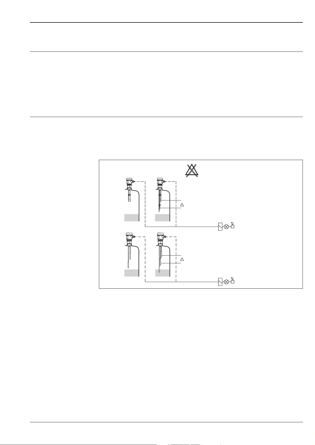
Measuring system Probes with integrated electronic insert (compact-instrument version)
The measuring system consists of:
•
FTW 31, FTW 32 with two/three rods or ropes and an electronic insert
•
Control units, switches or signal transmitters, e.g. process control systems PLC, relays, etc.
!
X
E
FTW 31
1 - 2 points
2 - 3 rods
s
FTW 32
1 - 2 points
2 - 3 ropes
s
L00-FTW3xxxx -14-05-xx-en-001
Independent of the tank material
Note!
The compact-instrument version with three probes or rods is always used in ∆s mode.
Endress + Hauser 3
Page 4
Liquipoint T FTW 31, FTW 32
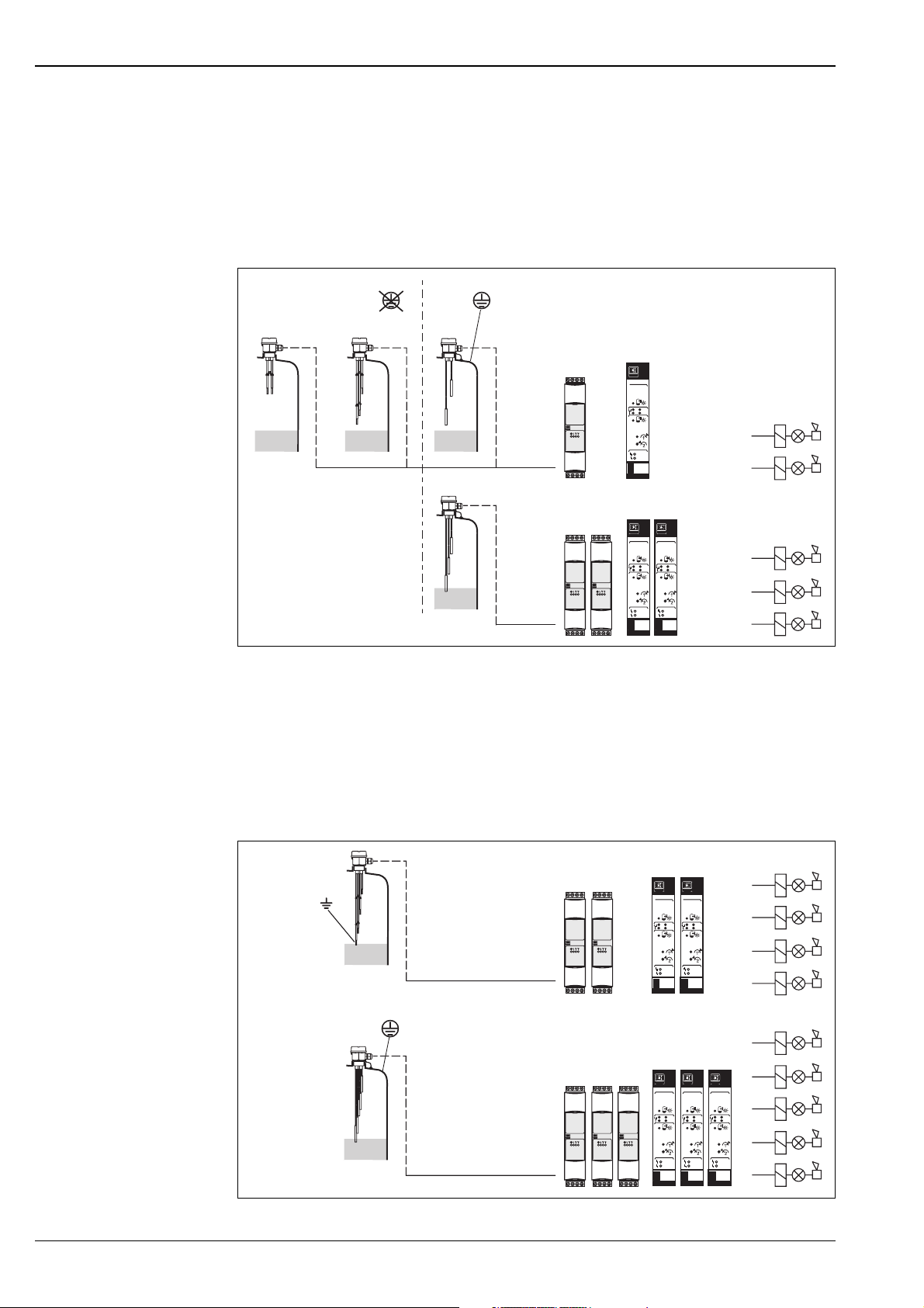
Probes without integrated electronic insert (separate-instrument version) for one or two
point detection respectively
The measuring system consists of:
•
FTW 31, FTW 32 with two/three rods or ropes
•
Nivotester FTW 325 or FTW 470 Z
•
Control units, switches or signal transmitters, e.g. process control systems PLC, relays, etc.
FTW 31/32
1 - 2 points
2 - 3 rods/ropes
FTW 325 or FTW 470 Z
FTW470Z
1
2
FTW 325
1
2
FTW 31/32
FTW 325 or FTW 470 Z
3 points
3 rods/ropes
FTW 325
FTW470Z
FTW470Z
1
1
2
2
FTW 325
1
1
2
2
L00-FTW3xxx x-14-05-xx-en-002
Switch points dependent on the tank material
Probes without integrated electronic insert for multiple point detection
The measuring system consists of:
•
FTW 31, FTW 32 with five rods or ropes
•
Two Nivotester FTW 325 or FTW 470 Z
•
Control units, switches or signal transmitters, e.g. process control systems PLC, relays, etc.
FTW 31/32
4 points
5 rods/ropes
FTW 325 or FTW 470 Z
FTW470Z
FTW 325FTW 325
FTW470Z
1
1
2
2
1
1
2
2
FTW 31/32
5 points
5 rods/ropes
FTW 325 or FTW 470 Z
FTW470Z
FTW 325FTW 325
FTW 325
FTW470Z
FTW470Z
1
1
2
1
2
1
2
2
1
1
2
2
L00-FTW3xxx x-14-05-xx-en-003
Switch points dependent on the tank material
4 Endress + Hauser
Page 5
Liquipoint T FTW 31, FTW 32
Input
Measured variable Resistance change between two conductors caused by the presence or absence of a conductive
product.
Measuring range (application)
The measuring range is dependent on the mounting location of the probes.
Rod probes can have a max. length of 4000 mm and rope probes up to 15 000 mm.
Input signal Probes covered => a measurable current is flowing between the probes.
Probes uncovered => there is no measurable current flowing between the probes.
Output
Electronic insert FEW 52 (DC-PNP)
Output signal
Three-wire direct current version
Preferred in conjunction with programmable logic controllers (PLC).
Positive signal at the switch output of the electronics (PNP).
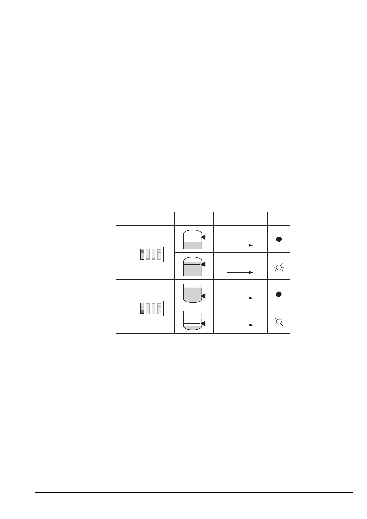
The output is blocked after the level limit is reached.
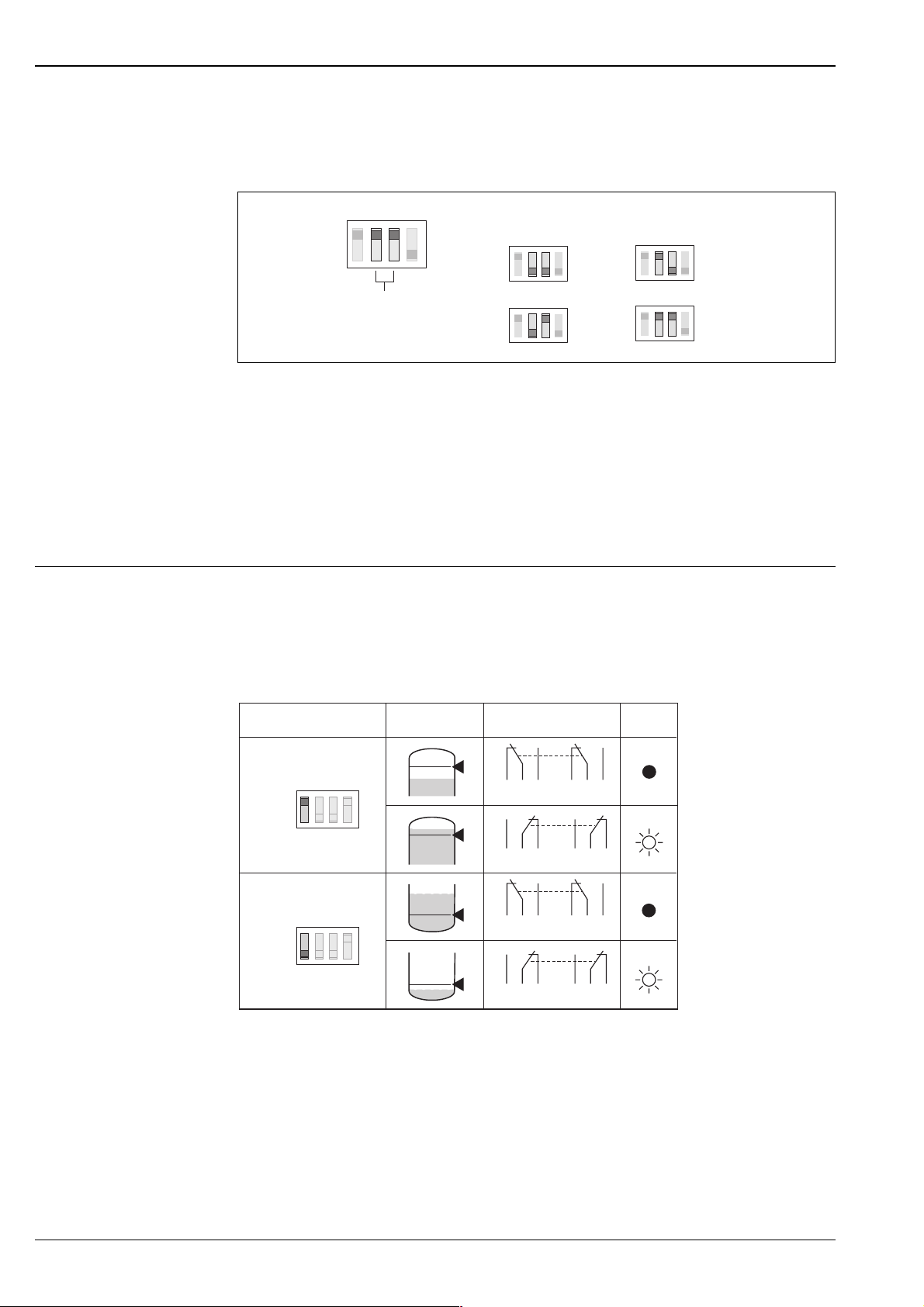
Fail-safe mode Switch point Output signal
MAX
Max.
L+
1 3
1 3
1
*
I
L
2
*
< 100 µA
rd
3
*
4
*
L+
I
L
Min.
MIN
*1 = load current (connected); *2 residual current (disconnected); *3 LED not lit; *4 LED lit
See also Electrical connection on page 8.
1 3
+
< 100 µA
1 3
L00-FTW3xxxx -15-05-xx-en-001
If the probe is covered and the red LED flashes continuously, the next more sensitive measuring
range has to be set. This ensures a safe switch point even if the conductivity of the medium varies
slightly.
Fail-safe mode
Selecting the correct fail-safe mode ensures that the output always runs in quiescent current
fail-safe.
•
Maximum fail-safe: the output voltage is 0 V if the switch point is exceeded
(probe covered), a fault occurs or the power supply fails.
•
Minimum fail-safe: the output voltage is 0 V if the switch point is undershot
(probe uncovered), a fault occurs or the power supply fails.
Switching delay
A switching delay of 2.0 s can be activated or deactivated via a DIL switch.
If the switching delay is set to 0 s, the device switches after approx. 0.3 s.
Endress + Hauser 5
Page 6
Liquipoint T FTW 31, FTW 32
Measuring ranges
A total of four measuring ranges (100 Ω; 1 kΩ; 10 kΩ; 100 kΩ) can be set via two DIL switches
(SENS). The setting on delivery is 100 kΩ.
Electronic insert FEW 54 (relay)
MAX
MIN
2 s
0 s
SENS = 100 - 100kΩΩ
100 Ω
1 kΩ
10 kΩ
100 kΩ
L00-FTW3xxx x-15-05-xx-xx-001
Signal on alarm
In the event of a power failure or a damaged probe: < 100 µΑ
Load
The load is switched via a transistor (PNP).
Cycled overload and short-circuit protection,
continuous ≤ 200 mA (short-circuit proof).
Residual voltage at transistor at I
max
< 2.9 V
Output signal
AC/DC connection with relay output
When connecting a device with high inductance, a spark barrier must be fitted to protect the relay
contact. A fine-wire fuse (load-dependent) protects the relay contact in the event of a short-circuit.
Both relay contacts switch simultaneously.
Fail-safe mode Switch point Output signal
MAX
Max.
Min.
MIN
354
354
354
354
1
*
687
2
*
687
687
687
rd
3
*
4
*
L00-FTW3xxx x-15-05-xx-en-002
*1 = relay energised; *2 relay de-energised; *3 LED not lit; *4 LED lit
See also Electrical connection on page 9.
If the probe is covered and the red LED flashes continuously, the next more sensitive measuring
range has to be set. This ensures a safe switch point even if the conductivity of the medium varies
slightly.
6 Endress + Hauser
Page 7
Liquipoint T FTW 31, FTW 32
Fail-safe mode
Selecting the correct fail-safe mode ensures that the relay always runs in quiescent current
fail-safe.
•
•
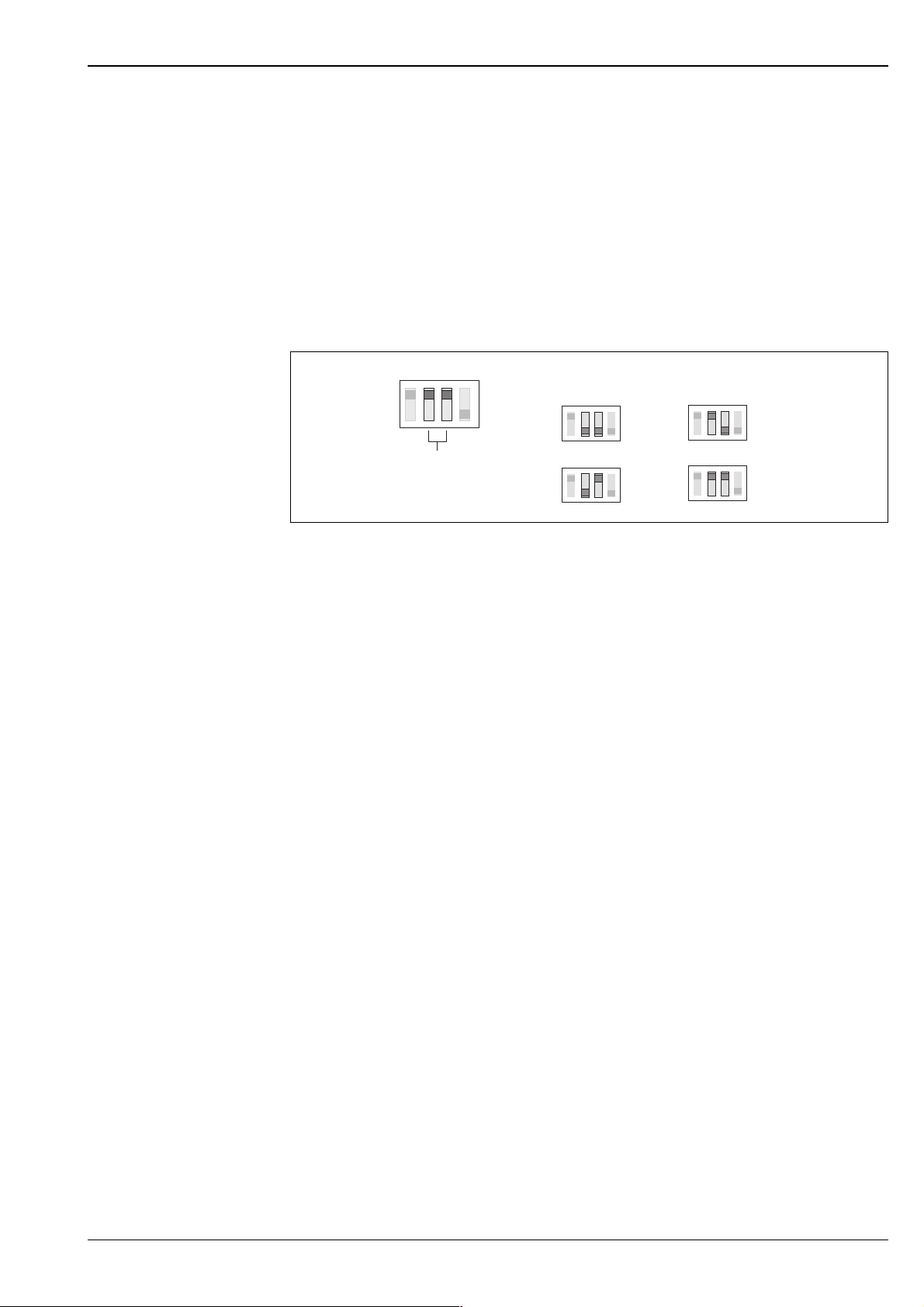
Measuring ranges
A total of four measuring ranges (100 Ω; 1 kΩ; 10 kΩ; 100 kΩ) can be set via two DIL switches
(SENS). The setting on delivery is 100 kΩ.
Maximum fail-safe: the relay de-energises when the switch point is exceeded
(probe covered), a fault occurs or the power supply fails.
Minimum fail-safe: the relay de-energises when the switch point is undershot
(probe uncovered), a fault occurs or the power supply fails.
MAX
MIN
2 s
0 s
SENS = 100 - 100kΩΩ
100 Ω
1 kΩ
10 kΩ
100 kΩ
L00-FTW3xxxx-15-05-xx-xx-001
Switching delay
A switching delay of 2.0 s can be activated or deactivated via a DIL switch.
If the switching delay is set to 0 s, the device switches after approx. 0.3 s.
Signal on alarm
Output signal in the event of a power failure or a damaged probe: relay de-energised.
Load
Loads are switched via 2 potential-free change-over contacts.
I~ max. 4 A, U~ max. 253 V;
P~ max. 1000 VA, cos ϕ = 1, P~ max. 700 VA, cos ϕ > 0.7;
I– max. 4 A to 30 V, I– max. 0.2 A to 150 V.
When connecting a functional extra-low voltage circuit with double insulation in accordance with
IEC 1010: the sum of the relay output and power supply voltages is max. 300 V.
Galvanic isolation
All input channels, output channels and relay contacts are galvanically isolated from each other.
Endress + Hauser 7
Page 8
Liquipoint T FTW 31, FTW 32
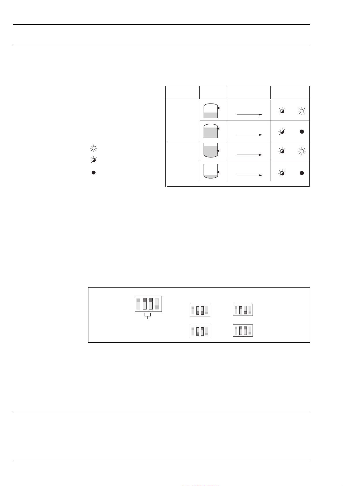
Electronic insert FEW 58 (NAMUR)
Output signal
For connecting to isolating amplifiers acc. to NAMUR (IEC 60947-5-6)
Output signal jump from high to low current on limit (H-L-edge).
L00-FTL5xxx x-07-05-
xx-xx-002
= lit
= flashes
= unlit
Fail-safe
circuit
Max.
Min.
Level Output signal LEDs
gn ye
2.2 …
+
6.5 mA
2 1
0.4 …
+
1.0 mA
2 1
2.2 …
+
6.5 mA
2 1
0.4 …
+
1.0 mA
2 1
L00-FTW3xxxx-04-05-xx-xx-006
Fail-safe mode
Selecting the correct fail-safe mode ensures that the relay always runs in quiescent current
fail-safe.
•
Maximum fail-safe: the output signal is < 1.0 mA when the switch point is exceeded
(probe covered), a fault occurs or the power supply fails.
•
Minimum fail-safe: the output signal is < 1.0 mA when the switch point is undershot
(probe uncovered), a fault occurs or the power supply fails.
Measuring ranges
A total of four measuring ranges (100 Ω; 1 kΩ; 10 kΩ; 100 kΩ) can be set via two DIL switches
(SENS). The setting on delivery is 100 kΩ.
MAX
MIN
2 s
0 s
SENS = 100 - 100kΩΩ
100 Ω
1 kΩ
10 kΩ
100 kΩ
L00-FTW3xxx x-15-05-xx-xx-001
Switching delay
A switching delay of 2.0 s can be activated or deactivated via a DIL switch.
If the switching delay is set to 0 s, the device switches after approx. 0.3 s.
Load
Refere to "Technical Data" date sheet of the connected isolating amplifier acc. to
NAMUR (IEC 60947-5-6)
Cable monitoring For probes without an electronic insert, an additional printed circuit board must be installed in the
housing, which enables cable monitoring. It is always switched or connected between rod/rope
1 and 2.
!
Note!
When using switching units (transmitters) that do not support cable monitoring, these must be
removed.
8 Endress + Hauser
Page 9
Liquipoint T FTW 31, FTW 32
Power supply
Electrical connection (wiring diagrams)
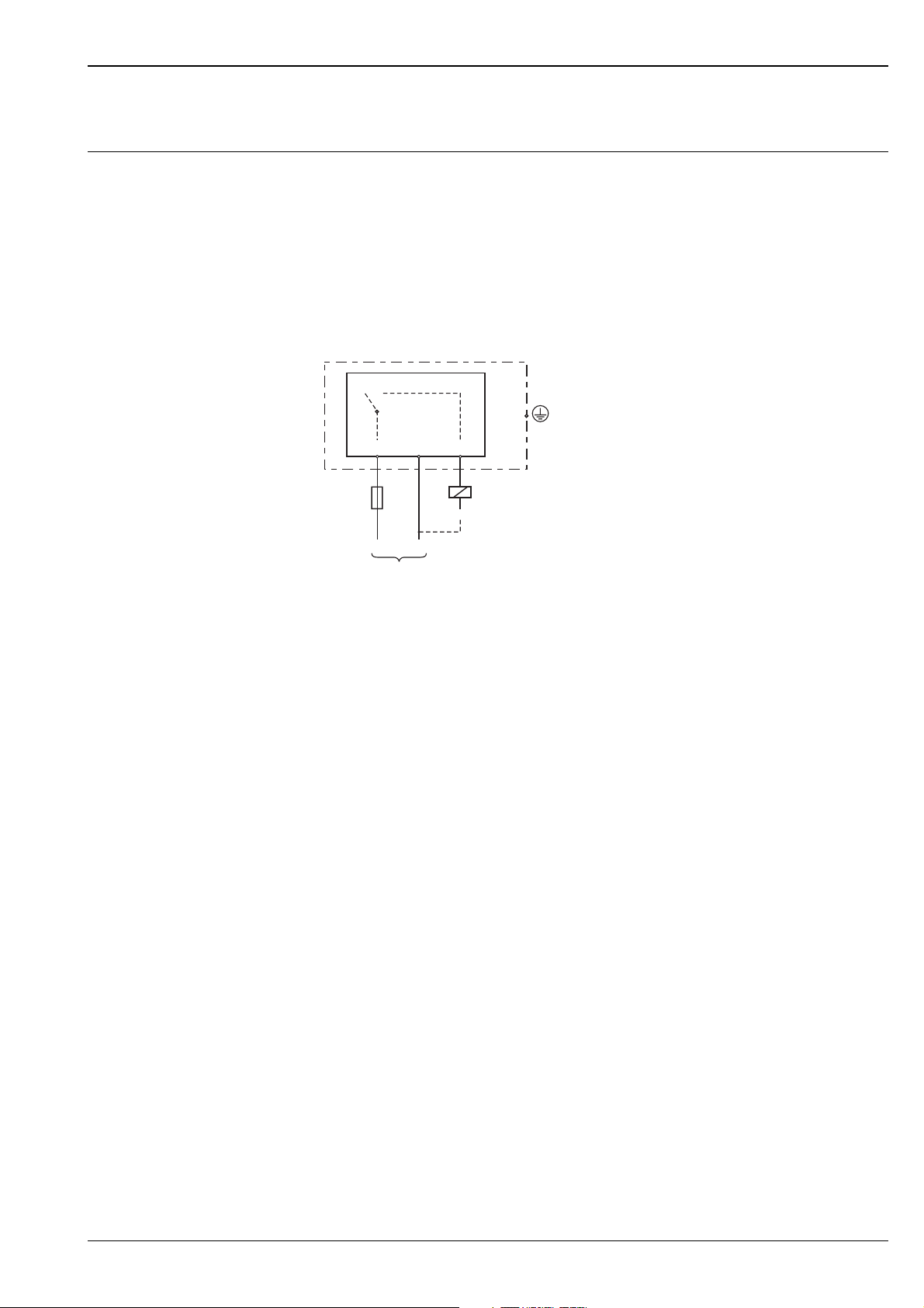
Compact instrumentation with FEW 52
Transistor circuit for load
The load connected to terminal 3 is switched by a transistor, contactless and therefore without
bouncing. In normal switching status, terminal 3 has a positive signal.
The transistor is blocked in the event of a level alarm or a power failure.
Protection against voltage peaks
When connecting a device with high inductance, always connect a voltage limiter.
FEW 52
M
123
F
L+ L–
Mains
Connecting the FEW 52 electronic insert.
(+)
R
–
L00-FTW3xxxx -04-05-xx-en-001
– F: Fine-wire fuse 500 mA, semi-time lag
– M: Ground connection to protective earth
Power supply (FEW 52)
•
Supply voltage: U= 10.8 V...45 V
•
Load connection: open collector; PNP
•
Switching voltage: max. 45 V
•
Connected load, continuous: max. 200 mA
•
Protected against reverse polarity
Power consumption
•
P < 1.1 W
Current consumption
•
I < 25 mA (without load)
Endress + Hauser 9
Page 10
Liquipoint T FTW 31, FTW 32
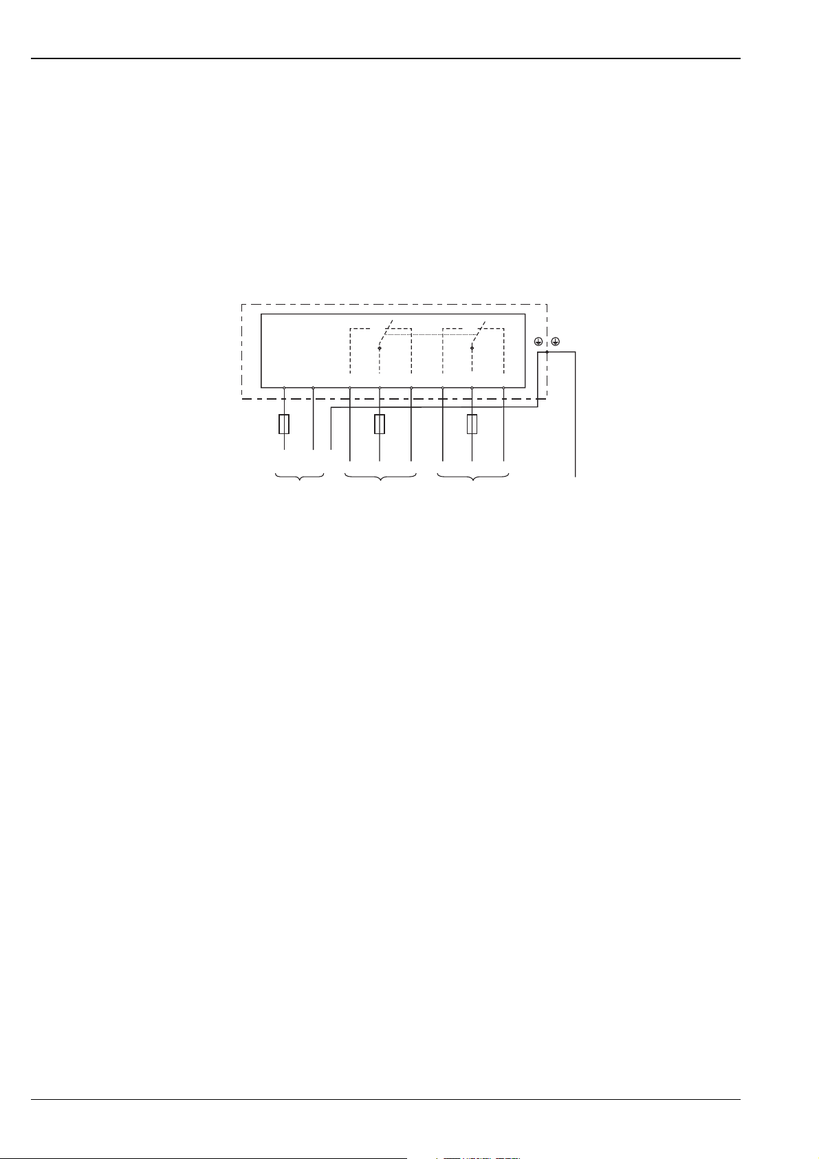
Compact instrumentation with FEW 54
Relay contact circuit for load
The connected load is switched via potential-free relay contacts (change-over contact).
In the event of a level alarm or a power failure, the relay contacts break the connections between
terminals 3 and 4 and terminals 6 and 7. The relays always switch simultaneously.
Protection against voltage peaks and short-circuits
When connecting a device with high inductance, fit a spark barrier to protect the relay contact.
A fine-wire fuse (load-dependent) can protect the relay contact in the event of a short-circuit.
FEW 54
12 4 78365
F
1
PE
L1 N
Connecting the FEW 54 electronic insert.
PE
Mains
F
2
Potential-free change-over contacts
ru– a+rua
F
2
M
Vessel
– F1: Fine-wire fuse 500 mA, semi-time lag
– F
: Fine-wire fuse to protect the relay contact, load-dependent
2
– M: Ground connection to protective earth (PE)
Power supply (FEW 54)
•
Supply voltage: U% 20 V…55 V DC or U& 20 V…253 V AC, 50/60 Hz
•
Peak inrush current: max. 2 A, max. 400 µs
•
Output: two potential-free change-over contacts
•
Contact load capacity: U~ max. 253 V, I~ max. 4 A, U% 30 V/4 A; 150 V/ 0.2 A
L00-FTW3xxx x-04-05-xx-en-002
Power consumption
•
P < 2,0 W
Current consumption
•
60 mA
10 Endress + Hauser
Page 11
Liquipoint T FTW 31, FTW 32
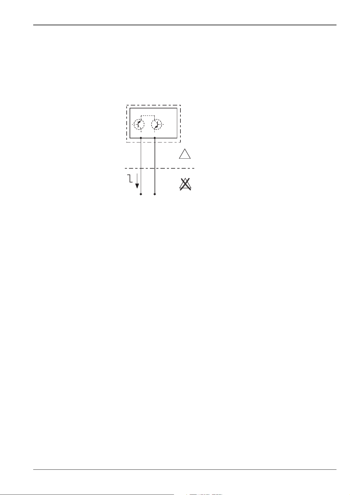
Compact instrumentation with FEW 58
To be used with isolating amplifiers acc. to NAMUR (IEC 60947-5-6)
Output signal jump from high to low current on limit (H-L-edge).
Signal transmission on a two-wire line:
H-L-edge 2.2 ... 6.5 mA / 0.4 ... 1.0 mA
When using a multiplex the cycle time must be set to a minimum of 2 s.
FEL 58
1
I
2
X
E
E
X
–
IEC 60947-5-6 (NAMUR)IEC 60947-5-6 (NAMUR)
+
Connecting the FEW 58 electronic insert.
Power supply (FEW 58)
Refere to "Technical Data" date sheet of the connected isolating amplifier acc. to
NAMUR (IEC 60947-5-6)
Signal on alarm
•
Output signal with damaged sensor: < 1.0 mA
L00-FTW3xxxx -04-05-xx-en-005
Endress + Hauser 11
Page 12
Liquipoint T FTW 31, FTW 32
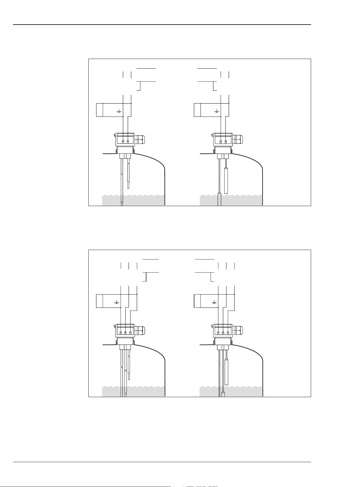
Separate instrumentation for two-rod or two-rope probes with cable monitoring
9
7
CH1
or
CH2
1
*
d2 d2
d4 d4
z2 z2
z4 z4
Max
11
22
FTW 325
FTW 470 Z
1
*
7
9
CH1
or
CH2
Max
L00-FTW3xxx x-04-05-xx-en-003
*1 Printed circuit board for cable monitoring
The power supply and evaluation are provided by switching units, e.g. Nivotester FTW 325 or FTW 470 Z
Separate instrumentation for three-rod or three-rope probes with cable monitoring
77
99
8
CH1
d4 d4
d2 d2
b2
CH2
1
*
b4
z4 z4
z2 z2
Max
Min
113322
*1 Printed circuit board for cable monitoring
The power supply and evaluation are provided by switching units, e.g. Nivotester FTW 325 or FTW 470 Z
FTW 325
FTW 470 Z
8
CH1
b2
b4
CH2
1
*
Min
Max
L00-FTW3xxx x-04-05-xx-xx-001
12 Endress + Hauser
Page 13
Liquipoint T FTW 31, FTW 32
7
8
9
10
7
8
9
10
4
5
6
17
4
5
6
17
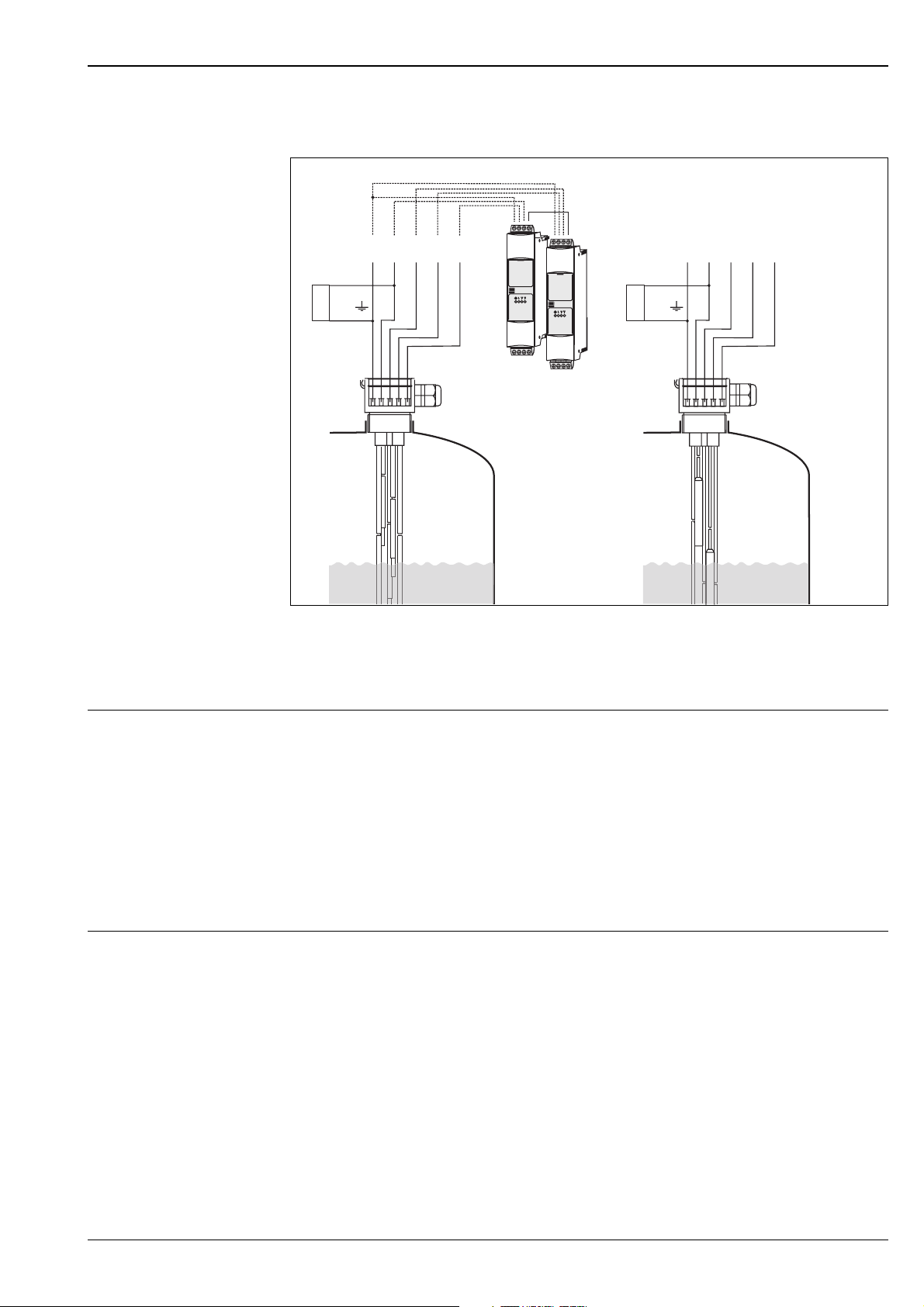
Separate instrumentation for five-rod or five-rope probes with cable monitoring
7
8
9
FTW 325
4
(M)
10
7
8
9
10
FTW 325
5
6
17
4
5
6
17
1
*
799 88
(S)
∆s
799
1
*
Max
2 21 14 45 53 3
8
8
off
Min
on
Max
∆s
Min
off
on
L00-FTW3xxxx -04-05-xx-en-004
*1 Printed circuit board for cable monitoring
The power supply and evaluation are provided by switching units, e.g. Nivotester FTW 325 or FTW 470 Z
Master (M) / Slave (S)
Cable entry M 20x1.5
•
Degree of protection: IP66
•
Quantity in F24 housing: 1 (separate-instrument version)
•
Quantity in F16 housing: 2 (compact-instrument version)
NPT 1/2"
•
Quantity in F24 housing: 1 (separate-instrument version)
•
Quantity in F16 housing: 2 (compact-instrument version)
•
Conductor cross-section (including wire end sleeve): 2.5 mm
Cable specifications Use a commercially available cable (25 Ω per wire).
Endress + Hauser 13
Page 14
Liquipoint T FTW 31, FTW 32
Accuracy with bui lt-in electronic insert
Reference operating conditions
Measuring error +/– 10 % at 100 Ω - 100 kΩ
Repeatability +/– 5 % at 100 Ω - 100 k
Hysteresis – 10% for the MAX probe, in reference to the switch point. ∆s φυνχτιον δεαχτιϖατεδ.
Switch-on delay < 3 s
Influence of ambient temperature
•
Ambient temperature: 23 °C
•
Medium temperature: 23 °C
•
Medium viscosity: medium must release the probe again (drain off).
•
Medium pressure pe: 0 bar
•
Probe installation: vertically from above
+/– 5 % at 1 kΩ - 10 kΩ
+/– 1 % at 1 k - 10 k
< 0,05 %/K
Installation conditions
Installation instructions Mounting location
The rod and rope probes are mounted predominantly in tanks made of plastic or metal.
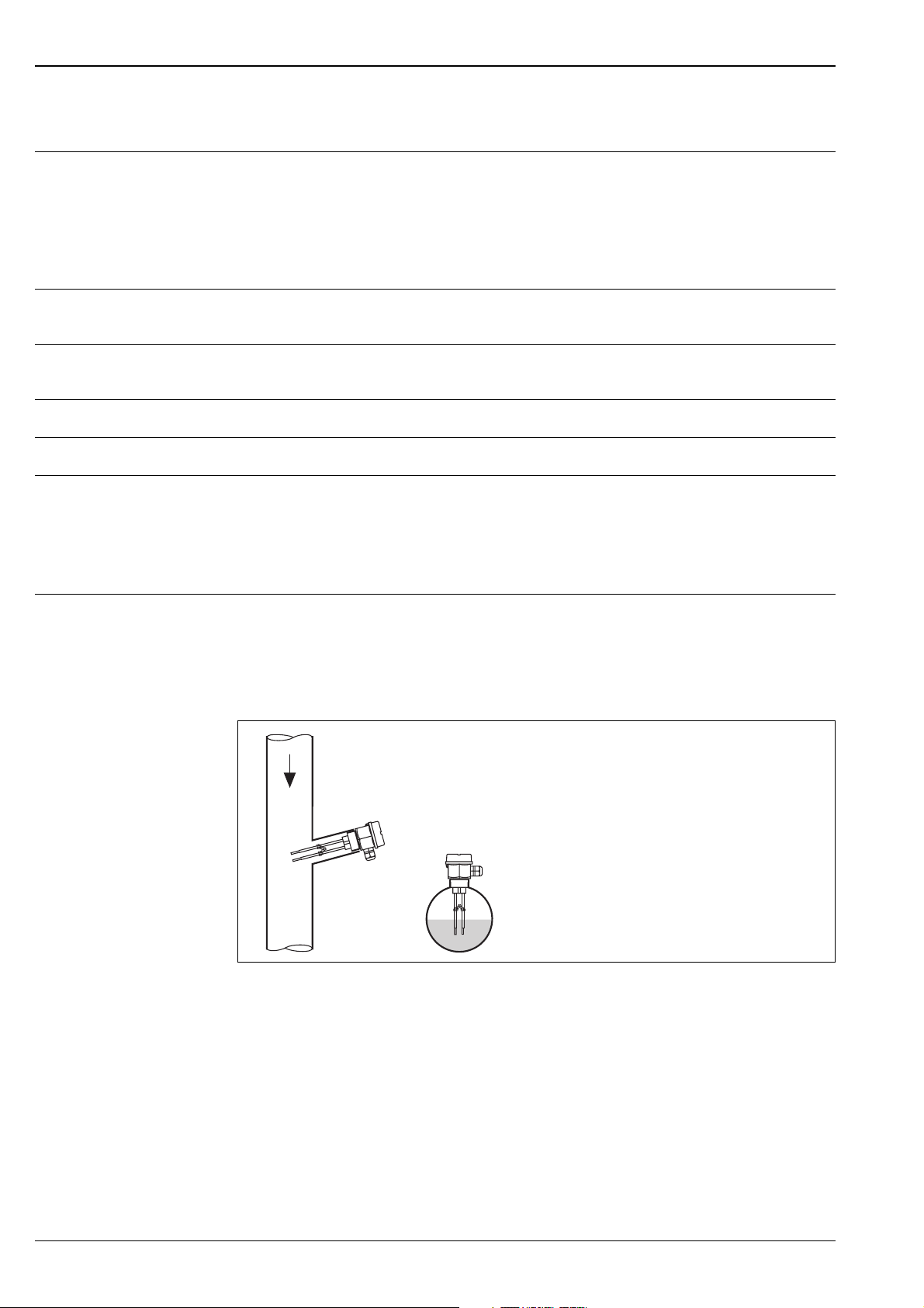
Piping (partially filled)
Two-rod probes can be used in piping as, for example, dry running protection for pumps.
L00-FTW3xxx x-11-05-xx-xx-001
14 Endress + Hauser
Page 15
Liquipoint T FTW 31, FTW 32
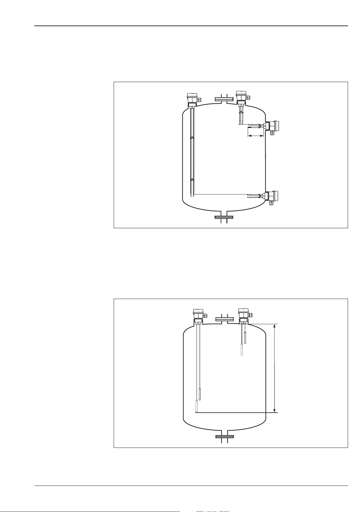
Orientation
Rod probes (Dimensions in mm)
Level limit detection for standard applications in tanks made of plastic or metal.
a.
b.
c.
200
d.
L00-FTW3xxxx-11-05-xx-xx-002
a. Vertical mounting, minimum detection; Probe length set to the level limit required;
Rods must not come into contact with the tank.
b. Vertical mounting, maximum detection; Probe length set to the level limit required
c. Lateral mounting, maximum detection; Maximum probe length 200 mm (only applies to two-rod probes).
d. Lateral mounting, minimum detection; Maximum probe length 200 mm (only applies to two-rod probes).
Rope probes (Dimensions in mm)
Level limit detection for standard applications in tanks made of plastic or metal.
a.
a. Vertical mounting, minimum detection; Rope length set to the level limit required;
Rope ends must not come into contact with the tank
b. Vertical mounting, maximum detection; Rope length set to the level limit required
b.
250 - 15000
L00-FTW3xxxx-11-05-xx-xx-003
Endress + Hauser 15
Page 16
Example applications
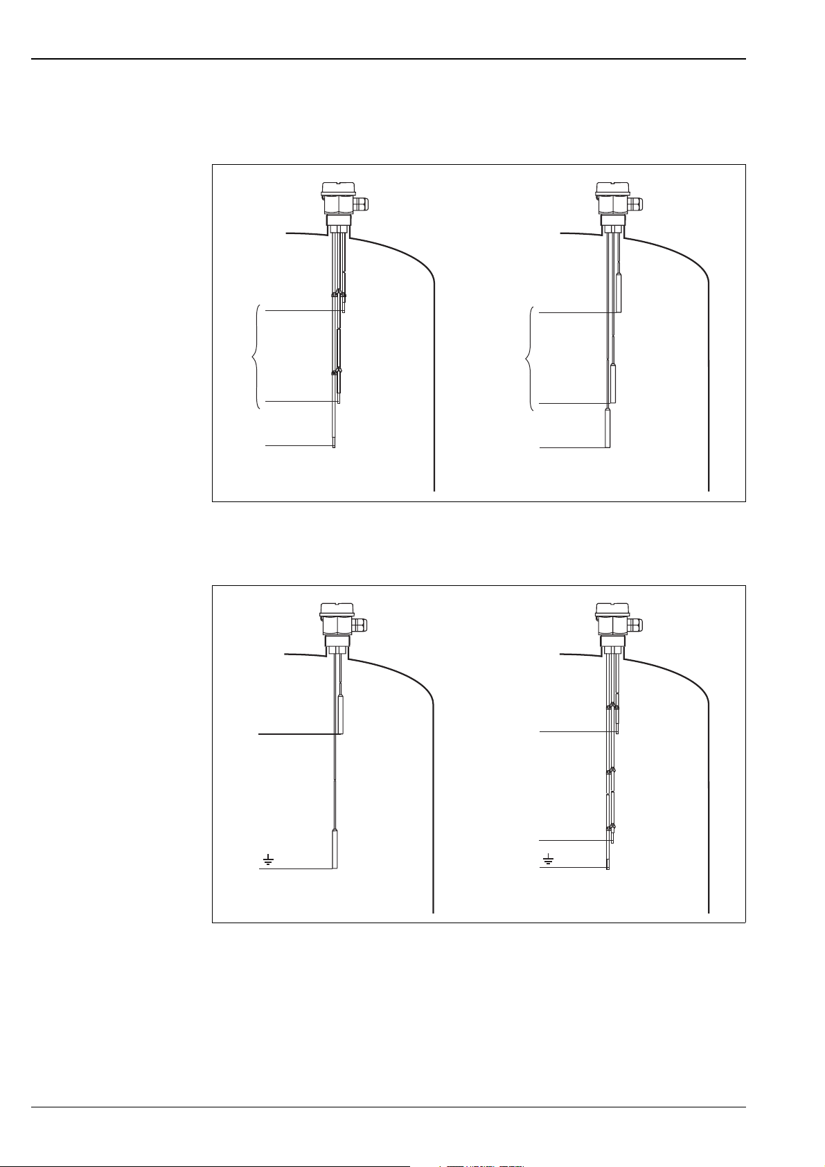
Level limit detection (standard applications)
Liquipoint T FTW 31, FTW 32
MAX
∆s
MIN
)
Two-point control (∆s) e.g. pump control
Level limit detection (standard applications)
MAX
∆s
MIN
)
L00-FTW3xxx x-15-05-xx-xx-002
MAX
MAX
MIN
L00-FTW3xxx x-15-05-xx-xx-003
Level limit detection (MAX),
maximum and minimum detection for compact-instrument devices only possible with
∆
s.
16 Endress + Hauser
Page 17
Liquipoint T FTW 31, FTW 32
Environment
Ambient temperature range
Non-hazardous area
–40 ... 70 °C
–40 ... 60 °C (for FEW 58 NAMUR)
Storage temperature –40 ... 80 °C
Climate class Tropicalised as per DIN EEC 68, part 2-38
Degree of protection IP66
Shock resistance Practical test
Vibration resistance
DIN 60068-2-64 / IEC 68-2-64: 20 ... 2000 Hz, 1 (m/s
(at min. rod length)
Electromagnetic compatibility
•
Interference Emission to EN 61326, Electrical Equipment Class B
Interference Immunity to EN 61326, Annex A (Industrial)
•
Use for separte-instrumented probes a screened cable between the probe and the switching
unit.
For installation instructions for screened cables and general instructions for EMC inspection
conditions of E+H devices, see also TI 241F.
2)2
/Hz
Medium temperature limits
!
Proces s co nd itions
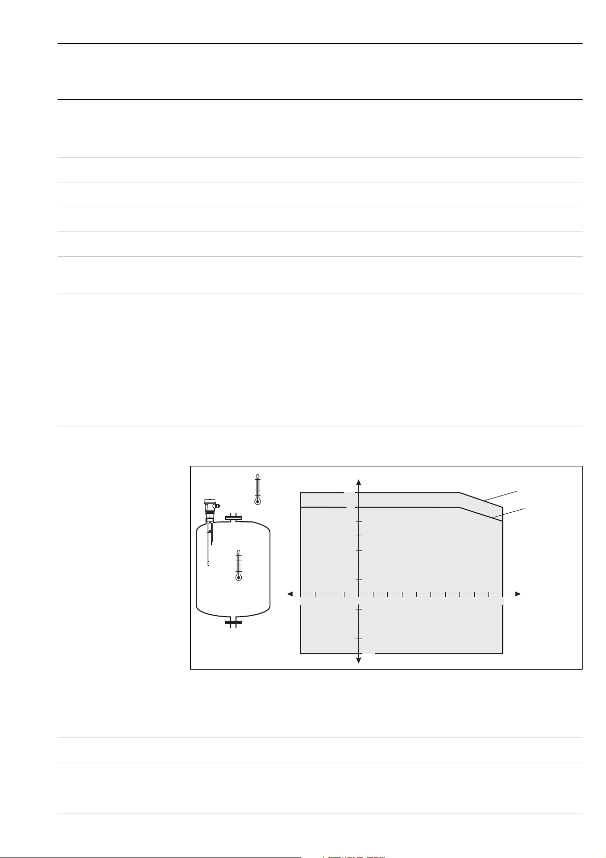
Permissible ambient temperature T1 at the housing as a function of the measuring material
temperature T
Note!
For separately instrumented devices (without FEW 5?) there are no restrictions in the indicated
temperature range.
in the vessel:
2
T
1
T
2
T
1
70
60
50
40
30
20
10
0
–20–30 –10 10 30 40 50 60 7020 80 90
0
–10
–20
–30
–40
FEW 52, FEW 54
100–40
T
FEW 58 (NAMUR)
2
Conductivity ≥ 10 µS
Limiting medium pressure
–1 ... 10 bar
range
Endress + Hauser 17
Page 18
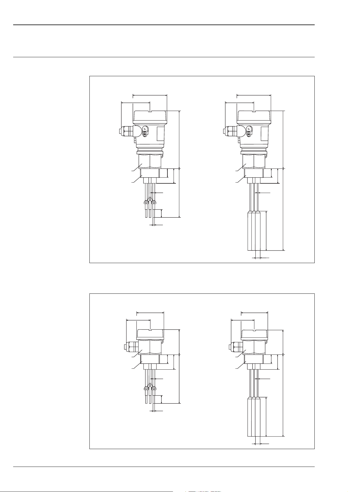
Liquipoint T FTW 31, FTW 32
Mechanical co nstruction
Design, dimensions Rod and rope version with G 1 1/2" (compact-instrument version with electronic insert)
FTW 31
ø85
max. 76
145
AF 55 AF 55
G 1½
ø5
ø4
22
37
G 1½
Probe length L
24
100 … 4 000 mm
max. 76
FTW 32
ø85
ø2,5
100
22
37
145
… 15 000 mm
Probe length L
250 mm
ø10
L00-FTW3xxx x-06-05-xx-en-001
Rod and rope version with G 1 1/2" (separate-instrument version without electronic insert)
max. 63
FTW 32
ø66
ø2,5
22
100
64
37
… 15 000 mm
Probe length L
250 mm
FTW 31
ø66
max. 63
64
AF 55 AF 55
G 1½ G 1½
ø5
ø4
22
37
Probe length L
24
100 … 4 000 mm
ø10
L00-FTW3xxx x-06-05-xx-en-002
18 Endress + Hauser
Page 19
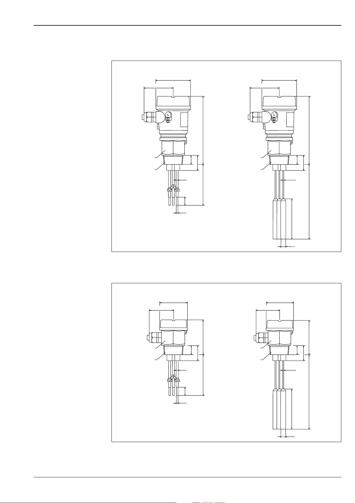
Liquipoint T FTW 31, FTW 32
Rod and rope version with NPT 1 1/2" (compact-instrument version with electronic insert)
FTW 31
ø85 ø85
max. 76 max. 76
168
AF 55 AF 55
NPT 1½ NPT 1½
ø5
ø4
23,5
38,5
Probe length L
24
100 … 4 000 mm
FTW 32
ø2,5
23,5
100
168
38,5
… 15 000 mm
Probe length L
250 mm
ø10
L00-FTW3xxxx -06-05-xx-en-003
Rod and rope version with NPT 1 1/2" (separate-instrument version without electronic insert)
max. 64
FTW 32
ø2,5
23,5
100
86
38,5
… 15 000 mm
Probe length L
250 mm
FTW 31
ø66 ø66
max. 64
86
AF 55 AF 55
NPT 1½ NPT 1½
ø5
ø4
23,5
38,5
Probe length L
24
100 … 4 000 mm
ø10
L00-FTW3xxxx -06-05-xx-en-004
Endress + Hauser 19
Page 20

Weight Separate-instrument version
Rod, 1 m long
FTW 31 with 2, 3 or 5 rods (415 g; 530 g; 760 g)
Rope, 1 m long
FTW 32 with 2, 3 or 5 ropes (390 g; 470 g; 640 g)
Compact-instrument version
Rod, 1 m long
FTW 31 with 2 or 3 rods (600 g; 720 g)
Rope, 1 m long
FTW 32 with 2 or 3 ropes (710 g; 800 g)
Material Probes
Rods
•
Rod: 1.4404 (316L)
•
Insulation: PP
Liquipoint T FTW 31, FTW 32
Ropes
•
Rope: 1.4571 (316Ti)
•
Insulation: FEP
•
Weight: 1.4435
Housing
F24 (separate-instrument version)
•
Housing: PPS
•
Cover: PBT
F16 (compact-instrument version)
•
Housing: PBT
•
Cover: PBT
•
Adapter: PBT
Process connections
•
G 1 1/2
•
NPT 1 1/2
Fitted electrodes Rod probes
Compact-instrument version: 2 or 3 rods; Separate-instrument version: 2, 3 or 5 rods
•
Diameter without insulation: 4 mm
•
Maximum rod length: 4000 mm
•
Minimum rod length: 100 mm
•
Thickness of insulation: 0.5 mm
•
Length of non-insulated area (tip of rod): 20 mm
•
Extraction forces (parallel probe rod): 1000 N
20 Endress + Hauser
Page 21

Liquipoint T FTW 31, FTW 32
Rope probes
Compact-instrument version: 2 or 3 rods; Separate-instrument version: 2, 3 or 5 rods
•
•
•
•
•
•
•
Diameter without insulation: 1 mm
Maximum rope length: 15000 mm
Minimum rope length: 250 mm
Thickness of insulation: 0.75 mm
Weight length: 100 mm (not insulated)
Weight diameter: 10 mm
Extraction forces (parallel probe rod): 500 N
Endress + Hauser 21
Page 22
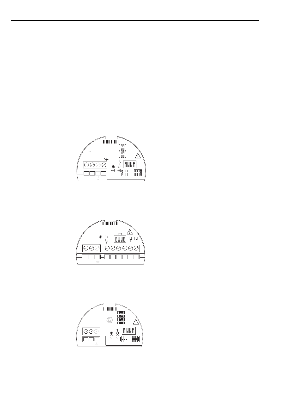
Human interface
Operating elements FEW 52, FEW 54, FEW 58
One DIL switch for min/max position
One DIL switch for 0 s or 2 s switching delay
Two DIL switches for setting the measuring ranges 100 Ω, 1 kΩ, 10 kΩ, 100 kΩ
Display elements Separate-instrument version
Dependent on the connected switching unit (e.g. FTW 325 or FTW 470 Z)
Compact-instrument version
FEW 52
One red light emitting diode: fault message, switching status
One green light emitting diode: operation
100
1k
10k
100k
1
3
U
10,8...45V DC
I max : 200mA
-
+
1 2 3
FEW52
1
3
Ω
MAX
MIN
Liquipoint T FTW 31, FTW 32
Ω
Ω
Ω
2s
0s
L00-FTW3xxx x-07-05-xx-xx-001
FEW 54
One red light emitting diode: fault message, switching status
One green light emitting diode: operation
20... 55V DC
20... 253V AC
L1 N
12
FEW54
SENS
0s / 2s
MIN/MAX
3568
47
345678
FEW 58
One yellow light emitting diode: fault message, switching status
One green light emitting diode: operation
100Ω
1kΩ
10kΩ
100kΩ
MAX
MIN
2s
0s
Namur
IEC 60947-5-6
-
+
1 2
FEW58
I < 1,0mA
I > 2,1mA
L00-FTW3xxx x-07-05-xx-xx-002
L00-FTW3xxx x-07-05-xx-xx-003
22 Endress + Hauser
Page 23
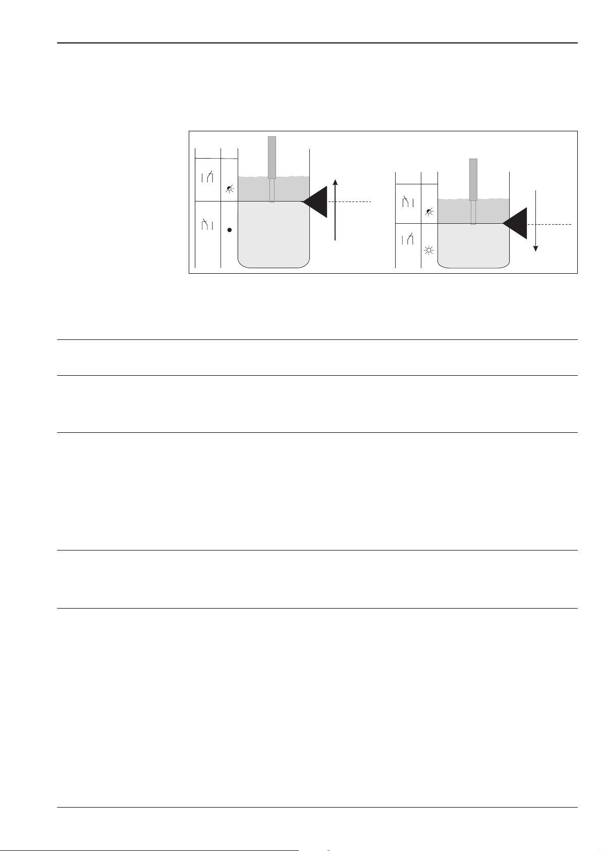
Liquipoint T FTW 31, FTW 32
!
Note! For FEW 52, FEW 54
If the probe is covered and the red LED flashes continuously, the next more sensitive measuring
range has to be set. This ensures a safe switch point even if the conductivity of the medium varies
slightly.
MAX
rd
Relais
MIN
Relais
3 4 5
6 7 8
3 4 5
6 7 8
rd
measuring range limit
3 4 5
6 7 8
3 4 5
6 7 8
measuring range limit
MAX
level
switch point
Certificates and approvals
CE mark The Liquipoint T meets the legal requirements of the EC directives.
Endress+Hauser confirms that the device has been successfully tested by applying the CE mark.
switch point
MIN
level
L00-FTW31xxx -15-05-xx-en-001
Overspill protection Approvals
•
WHG
•
Leak test (Leakage)
Other standards and guidelines
Other standards and guidelines that were observed during the design and development of the
Liquipoint T FTW 31 and FTW 32.
•
Low voltage equipment directive (73/ 23/ EEC)
•
DIN EN 61010 part 1, 2001
Safety regulations for electrical equipment for measurement, control and laboratory use
Part 1: General requirements
•
EN 61326
Electrical equipment for measurement, control and laboratory use EMC requirements
Ex-approvals The Endress+Hauser sales office provides information on the currently suppliable Ex versions
(ATEX EEx ia and ATEX EEx nA/C(L)). All data relevant for explosion protection can be found in
separate Ex documentation (see: Supplementary Documentation on page 26). This can be
viewed as necessary.
•
Type of protection
[EEx ia] IIC (FEW 58)
•
[EEx na/C(L)] IIC (FEW 52, FEW 54)
Endress + Hauser 23
Page 24
Ordering information
Liquipoint T FTW 31, FTW 32
Liquipoint FTW 31
10 Certificates
A Version for non-hazardous areas
B Version for non-hazardous areas, WHG, Leakage detection
C ATEX II 3 G EEx nA/C(L) IIC T6, WHG
D ATEX II 2 G EEx ia IIC T6
YSpecial version
20 Process connection and material
1 Threaded connection G 1 1/2", PPS
2 Threaded connection NPT 1 1/2", PPS
9 Special version
30 Quantity and material of rods
A2 2 rods, 316L
A3 3 rods, 316L
A5 5 rods, 316L
Y9 Special version
40 Length of probe L, 100 ... 4000 mm
A mm L, probe length
B inch L, probe length
C 1000 mm L, probe length
D 2000 mm L, probe length
Y Special version
50 Housing and cable entry
A Plastic housing IP66, M20x1.5
B Plastic housing IP66, NPT 1/2"
C Plastic housing IP66, G 1/2"
Y Special version
60 Electronic insert
0 Without electronic insert
1 FEW 52/54 retrofit
2 FEW 52 output PNP 10.8 ... 45 V DC
4 FEW 54 relay output 20... 253 V AC, 20...55 V DC
8 * FEW 58 output NAMUR
9 Special version
70 Additional equipment
A Without additional equipment
Y Sonderausführung
FTW 31 complete product designation
* Available from autumn 2003
24 Endress + Hauser
Page 25
Liquipoint T FTW 31, FTW 32
Liquipoint FTW 32
10 Certificates
A Version for non-hazardous areas
B Version for non-hazardous areas, WHG, Leakage detection
C ATEX II 3 G EEx nA/C(L) IIC T6, WHG
D ATEX II 2 G EEx ia IIC T6
YSpecial version
20 Process connection and material
1 Threaded connection G 1 1/2", PPS
2 Threaded connection NPT 1 1/2", PPS
9 Special version
30 Quantity and material of ropes
D2 2 ropes, 316Ti
D3 3 ropes, 316Ti
D5 5 ropes, 316Ti
Y9 Special version
40 Length of probe L, 250 ... 15000 mm
A mm L, probe length
B inch L, probe length
Y Special version
50 Housing and cable entry
A Plastic housing IP66, M20x1.5
B Plastic housing IP66, NPT 1/2"
C Plastic housing IP66, G 1/2"
Y Special version
60 Electronic insert
0 Without electronic insert
1 FEW 52/54 retrofit
2 FEW 52 output PNP 10.8 ... 45 V DC
4 FEW 54 relay output 20... 253 V AC, 20...55 V DC
8 * FEW 58 output NAMUR
9 Special version
70 Additional equipment
A Without additional equipment
Y Special version
FTW 32 complete product designation
* Available from autumn 2003
Endress + Hauser 25
Page 26

Accessories
Liquipoint T Lock nut G 1 1/2"
Hexagon, AF 60
TN 52014146
Elektronic insert FEW 52
Output PNP 10.8 ... 45 V DC
PN 52017271
Elektronic insert FEW 54
Output Relais 20 ... 253 V AC, 20 ... 55 V DC
PN 52017272
Elektronic insert FEW 58
Output NAMUR (IEC 60947-5-6)
PN 52017273
Supplementa ry Docu m en t a tion
Liquipoint T FTW 31, FTW 32
Operating Instructions
Certificates WHG
•
Liquipoint T
FTW 31, FTW 32 (separate-instrument version)
KA 203F/00
•
Liquipoint T
FTW 31, FTW 32 (compact-instrument version)
KA 204F/00
•
Liquipoint T
ZE 043F/00
ATEX II 3G EEx nA/C(L) IIC T6
•
Liquipoint T
XA 226F/00
ATEX II 2G EEx ia IIC T6
•
Liquipoint T
XA 230F/00
26 Endress + Hauser
Page 27

Liquipoint T FTW 31, FTW 32
Endress + Hauser 27
Page 28

Liquipoint T FTW 31, FTW 32
11.01
TI 375F/00/en/07.03
SL/FM+SGML 6.0 ProMoDo
Endress+Hauser GmbH+Co.
Instruments International
P.O. Box 2222
D-79574 Weil am Rhein
Germany
Tel. (07621) 975-02
Tx 773926
Fax (07621) 975 345
e-mail: [email protected]
Internet:
http://www.endress.com
 Loading...