

Endress+Hauser Liquiphant M FTL50, Liquiphant M FTL50H, Liquiphant M FTL51, Liquiphant M FTL51H Technical Information
Page 1
Technical Information
Liquiphant M FTL50(H), FTL51(H)
Vibration Limit Switch
Level limit switch for all liquids.
Suitable for use in hazardous areas, food and pharmaceuticals
The function is not affected by flow, turbulence, bubbles,
foam, vibration, bulk solids content or build-up.
The Liquiphant is thus the ideal substitute for float
switches.
FTL50:
Compact design, ideal for mounting in pipes and for
installation in areas difficult to access
FTL51:
With extension pipe up to 3 m
(6 m on request)
FTL50H, FTL51H:
With polished tuning fork and easy-to-clean process
connections and housings for food and pharmaceutical
applications.
High corrosion-resistant AlloyC4 (2.4610) is available for
the fork and process connections for applications in very
aggressive liquids.
EEx ia, EEx de and EEx d protection enable it to be used
in hazardous areas.
Your benefits
• Use in safety systems requiring functional safety
to SIL2/SIL3 in accordance with IEC 61508/
IEC 61511-1
• Large number of process connections to choose from:
universal usage
• Wide variety of electronics, e.g. NAMUR, relay,
thyristor, PFM signal output: the right connection for
Application
The Liquiphant M is a level limit switch for use in all
liquids
– for process temperatures of –50 °C to 150 °C
– for pressures up to 100 bar
– for viscosity up to 10000 mm
– for densities 0.5 g/cm3 or 0.7 g/cm3 other settings
available on request
– foam detection on request
2
/s
every process control system
• PROFIBUS PA protocol:
for commissioning and maintenance
• No calibration: quick, low-cost start-up
• No mechanically moving parts: no maintenance,
no wear, long operating life
• Monitoring of fork for damage: guaranteed function
• FDA approved materials (PFA Edlon)
TI328F/00/en
Page 2

Table of contents
Liquiphant M FTL50(H), FTL51(H)
Application . . . . . . . . . . . . . . . . . . . . . . . . . . . . . . . . . 4
Level limit detection . . . . . . . . . . . . . . . . . . . . . . . . . . . . . . . . . . . 4
Function and system design. . . . . . . . . . . . . . . . . . . . . 4
Measuring principle . . . . . . . . . . . . . . . . . . . . . . . . . . . . . . . . . . . 4
Modularity . . . . . . . . . . . . . . . . . . . . . . . . . . . . . . . . . . . . . . . . . . 4
Electronic versions for level limit switches . . . . . . . . . . . . . . . . . . 5
Electronic versions for level sensor . . . . . . . . . . . . . . . . . . . . . . . . 5
Galvanic isolation . . . . . . . . . . . . . . . . . . . . . . . . . . . . . . . . . . . . . 5
Design . . . . . . . . . . . . . . . . . . . . . . . . . . . . . . . . . . . . . . . . . . . . . 5
Input . . . . . . . . . . . . . . . . . . . . . . . . . . . . . . . . . . . . . . 5
Measured variable . . . . . . . . . . . . . . . . . . . . . . . . . . . . . . . . . . . . 5
Measuring range (detection range) . . . . . . . . . . . . . . . . . . . . . . . . 5
Product density . . . . . . . . . . . . . . . . . . . . . . . . . . . . . . . . . . . . . . 5
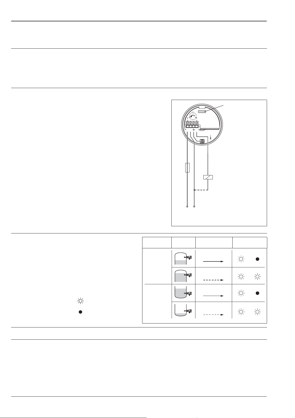
Electronic insert FEL51 (AC 2-wire) . . . . . . . . . . . . . . 6
Power supply . . . . . . . . . . . . . . . . . . . . . . . . . . . . . . . . . . . . . . . . 6
Electrical connection . . . . . . . . . . . . . . . . . . . . . . . . . . . . . . . . . . 6
Output signal . . . . . . . . . . . . . . . . . . . . . . . . . . . . . . . . . . . . . . . . 6
Signal on alarm . . . . . . . . . . . . . . . . . . . . . . . . . . . . . . . . . . . . . . 6
Connectable load . . . . . . . . . . . . . . . . . . . . . . . . . . . . . . . . . . . . . 6
Electronics FEL51 (AC, in compact housing) . . . . . . . . 7
Power supply . . . . . . . . . . . . . . . . . . . . . . . . . . . . . . . . . . . . . . . . 7
Electrical connection . . . . . . . . . . . . . . . . . . . . . . . . . . . . . . . . . . 7
Output signal . . . . . . . . . . . . . . . . . . . . . . . . . . . . . . . . . . . . . . . . 7
Signal on alarm . . . . . . . . . . . . . . . . . . . . . . . . . . . . . . . . . . . . . . 7
Connectable load . . . . . . . . . . . . . . . . . . . . . . . . . . . . . . . . . . . . . 7
Electronic insert FEL52 (DC PNP) . . . . . . . . . . . . . . . . 8
Power supply . . . . . . . . . . . . . . . . . . . . . . . . . . . . . . . . . . . . . . . . 8
Electrical connection . . . . . . . . . . . . . . . . . . . . . . . . . . . . . . . . . . 8
Output signal . . . . . . . . . . . . . . . . . . . . . . . . . . . . . . . . . . . . . . . . 8
Signal on alarm . . . . . . . . . . . . . . . . . . . . . . . . . . . . . . . . . . . . . . 8
Connectable load . . . . . . . . . . . . . . . . . . . . . . . . . . . . . . . . . . . . . 8
Electronics FEL52 (DC PNP, in compact housing) . . . . 9
Power supply . . . . . . . . . . . . . . . . . . . . . . . . . . . . . . . . . . . . . . . . 9
Electrical connection . . . . . . . . . . . . . . . . . . . . . . . . . . . . . . . . . . 9
Output signal . . . . . . . . . . . . . . . . . . . . . . . . . . . . . . . . . . . . . . . 9
Signal on alarm . . . . . . . . . . . . . . . . . . . . . . . . . . . . . . . . . . . . . 10
Connectable load . . . . . . . . . . . . . . . . . . . . . . . . . . . . . . . . . . . . 10
Electronic insert FEL54 (AC/DC with relay output) . 11
Power supply . . . . . . . . . . . . . . . . . . . . . . . . . . . . . . . . . . . . . . . 11
Electrical connection . . . . . . . . . . . . . . . . . . . . . . . . . . . . . . . . . 11
Output signal . . . . . . . . . . . . . . . . . . . . . . . . . . . . . . . . . . . . . . . 11
Signal on alarm . . . . . . . . . . . . . . . . . . . . . . . . . . . . . . . . . . . . . 11
Connectable load . . . . . . . . . . . . . . . . . . . . . . . . . . . . . . . . . . . . 11
Connectable load . . . . . . . . . . . . . . . . . . . . . . . . . . . . . . . . . . . . 12
Electronic insert FEL56 (NAMUR L-H edge) . . . . . . . 13
Power supply . . . . . . . . . . . . . . . . . . . . . . . . . . . . . . . . . . . . . . . 13
Electrical connection . . . . . . . . . . . . . . . . . . . . . . . . . . . . . . . . . 13
Output signal . . . . . . . . . . . . . . . . . . . . . . . . . . . . . . . . . . . . . . . 13
Signal on alarm . . . . . . . . . . . . . . . . . . . . . . . . . . . . . . . . . . . . . 13
Connectable load . . . . . . . . . . . . . . . . . . . . . . . . . . . . . . . . . . . . 13
Electronic insert FEL58 (NAMUR H-L edge) . . . . . . . 14
Power supply . . . . . . . . . . . . . . . . . . . . . . . . . . . . . . . . . . . . . . . 14
Electrical connection . . . . . . . . . . . . . . . . . . . . . . . . . . . . . . . . . 14
Output signal . . . . . . . . . . . . . . . . . . . . . . . . . . . . . . . . . . . . . . . 14
Signal on alarm . . . . . . . . . . . . . . . . . . . . . . . . . . . . . . . . . . . . . 14
Connectable load . . . . . . . . . . . . . . . . . . . . . . . . . . . . . . . . . . . . 14
Electronics FEL58 (NAMUR H-L edge,
in compact housing). . . . . . . . . . . . . . . . . . . . . . . . . . 15
Power supply . . . . . . . . . . . . . . . . . . . . . . . . . . . . . . . . . . . . . . . 15
Electrical connection . . . . . . . . . . . . . . . . . . . . . . . . . . . . . . . . . 15
Output signal . . . . . . . . . . . . . . . . . . . . . . . . . . . . . . . . . . . . . . . 15
Signal on alarm . . . . . . . . . . . . . . . . . . . . . . . . . . . . . . . . . . . . . 15
Connectable load . . . . . . . . . . . . . . . . . . . . . . . . . . . . . . . . . . . . 15
Electronic insert FEL57 (PFM). . . . . . . . . . . . . . . . . . 16
Power supply . . . . . . . . . . . . . . . . . . . . . . . . . . . . . . . . . . . . . . . 16
Electrical connection . . . . . . . . . . . . . . . . . . . . . . . . . . . . . . . . . 16
Output signal . . . . . . . . . . . . . . . . . . . . . . . . . . . . . . . . . . . . . . . 17
Signal on alarm . . . . . . . . . . . . . . . . . . . . . . . . . . . . . . . . . . . . . 17
Connectable load . . . . . . . . . . . . . . . . . . . . . . . . . . . . . . . . . . . . 17
Electronic insert FEL50A (PROFIBUS PA) . . . . . . . . . 18
Electrical connection . . . . . . . . . . . . . . . . . . . . . . . . . . . . . . . . . 18
Output signal . . . . . . . . . . . . . . . . . . . . . . . . . . . . . . . . . . . . . . . 19
Signal on alarm . . . . . . . . . . . . . . . . . . . . . . . . . . . . . . . . . . . . . 19
Connection and function . . . . . . . . . . . . . . . . . . . . . . 20
Connecting cables . . . . . . . . . . . . . . . . . . . . . . . . . . . . . . . . . . . 20
Fail-safe mode . . . . . . . . . . . . . . . . . . . . . . . . . . . . . . . . . . . . . . 20
Switching time . . . . . . . . . . . . . . . . . . . . . . . . . . . . . . . . . . . . . . 20
Switch-on behaviour . . . . . . . . . . . . . . . . . . . . . . . . . . . . . . . . . 20
Performance characteristics. . . . . . . . . . . . . . . . . . . . 20
Reference operating conditions . . . . . . . . . . . . . . . . . . . . . . . . . . 20
Maximum measured error . . . . . . . . . . . . . . . . . . . . . . . . . . . . . 20
Repeatability . . . . . . . . . . . . . . . . . . . . . . . . . . . . . . . . . . . . . . . 20
Hysteresis . . . . . . . . . . . . . . . . . . . . . . . . . . . . . . . . . . . . . . . . . 20
Influence of medium temperature . . . . . . . . . . . . . . . . . . . . . . . 20
Influence of product density . . . . . . . . . . . . . . . . . . . . . . . . . . . . 20
Influence of medium pressure . . . . . . . . . . . . . . . . . . . . . . . . . . 20
Electronic insert FEL55 (8/16 mA) . . . . . . . . . . . . . . 12
Power supply . . . . . . . . . . . . . . . . . . . . . . . . . . . . . . . . . . . . . . . 12
Electrical connection . . . . . . . . . . . . . . . . . . . . . . . . . . . . . . . . . 12
Output signal . . . . . . . . . . . . . . . . . . . . . . . . . . . . . . . . . . . . . . . 12
Signal on alarm . . . . . . . . . . . . . . . . . . . . . . . . . . . . . . . . . . . . . 12
2 Endress+Hauser
Operating conditions . . . . . . . . . . . . . . . . . . . . . . . . . 21
Installation . . . . . . . . . . . . . . . . . . . . . . . . . . . . . . . . . . . . . . . . . 21
Examples of mounting . . . . . . . . . . . . . . . . . . . . . . . . . . . . . . . . 21
Orientation . . . . . . . . . . . . . . . . . . . . . . . . . . . . . . . . . . . . . . . . 23
Page 3

Liquiphant M FTL50(H), FTL51(H)
Environment . . . . . . . . . . . . . . . . . . . . . . . . . . . . . . . 23
Ambient temperature range . . . . . . . . . . . . . . . . . . . . . . . . . . . . 23
Ambient temperature limits . . . . . . . . . . . . . . . . . . . . . . . . . . . . 23
Storage temperature . . . . . . . . . . . . . . . . . . . . . . . . . . . . . . . . . . 24
Climate class . . . . . . . . . . . . . . . . . . . . . . . . . . . . . . . . . . . . . . . 24
Degree of protection . . . . . . . . . . . . . . . . . . . . . . . . . . . . . . . . . 24
Vibration resistance . . . . . . . . . . . . . . . . . . . . . . . . . . . . . . . . . . 24
Electromagnetic compatibility . . . . . . . . . . . . . . . . . . . . . . . . . . 24
Medium conditions . . . . . . . . . . . . . . . . . . . . . . . . . . 24
Medium temperature range . . . . . . . . . . . . . . . . . . . . . . . . . . . . 24
Thermal shock . . . . . . . . . . . . . . . . . . . . . . . . . . . . . . . . . . . . . . 24
Medium pressure pe . . . . . . . . . . . . . . . . . . . . . . . . . . . . . . . . . 24
Test pressure . . . . . . . . . . . . . . . . . . . . . . . . . . . . . . . . . . . . . . . 24
State of aggregation . . . . . . . . . . . . . . . . . . . . . . . . . . . . . . . . . . 24
Density . . . . . . . . . . . . . . . . . . . . . . . . . . . . . . . . . . . . . . . . . . . 25
Viscosity . . . . . . . . . . . . . . . . . . . . . . . . . . . . . . . . . . . . . . . . . . 25
Solids content . . . . . . . . . . . . . . . . . . . . . . . . . . . . . . . . . . . . . . 25
Mechanical construction . . . . . . . . . . . . . . . . . . . . . . 25
Design . . . . . . . . . . . . . . . . . . . . . . . . . . . . . . . . . . . . . . . . . . . . 25
Dimensions in mm (1 mm = 0,0394 in) . . . . . . . . . . . . . . . . . . . 26
Weights . . . . . . . . . . . . . . . . . . . . . . . . . . . . . . . . . . . . . . . . . . . 30
Material . . . . . . . . . . . . . . . . . . . . . . . . . . . . . . . . . . . . . . . . . . . 30
Process connections . . . . . . . . . . . . . . . . . . . . . . . . . . . . . . . . . . 31
System Information . . . . . . . . . . . . . . . . . . . . . . . . . . . . . . . . . . 50
Human interface . . . . . . . . . . . . . . . . . . . . . . . . . . . . 31
Electronic inserts . . . . . . . . . . . . . . . . . . . . . . . . . . . . . . . . . . . . 31
Compact housings . . . . . . . . . . . . . . . . . . . . . . . . . . . . . . . . . . . 32
Operating concept . . . . . . . . . . . . . . . . . . . . . . . . . . . . . . . . . . . 34
Certificates and approvals . . . . . . . . . . . . . . . . . . . . . 35
General approvals . . . . . . . . . . . . . . . . . . . . . . . . . . . . . . . . . . . 35
Other certificates . . . . . . . . . . . . . . . . . . . . . . . . . . . . . . . . . . . . 35
Combination of housings and electronic inserts . . . . . . . . . . . . . 35
Ordering information . . . . . . . . . . . . . . . . . . . . . . . . 37
Product structure Liquiphant M
FTL50, FTL51 . . . . . . . . . . . . . . . . . . . . . . . . . . . . . . . . . . . . . . 37
Product structure Liquiphant M
FTL50H, FTL51H . . . . . . . . . . . . . . . . . . . . . . . . . . . . . . . . . . . 41
Accessories . . . . . . . . . . . . . . . . . . . . . . . . . . . . . . . . 44
Welding neck G ¾ . . . . . . . . . . . . . . . . . . . . . . . . . . . . . . . . . . . 44
Welding neck G 1 . . . . . . . . . . . . . . . . . . . . . . . . . . . . . . . . . . . 44
Welding neck G 1 . . . . . . . . . . . . . . . . . . . . . . . . . . . . . . . . . . . 45
Welding neck . . . . . . . . . . . . . . . . . . . . . . . . . . . . . . . . . . . . . . 45
DRD welding flange . . . . . . . . . . . . . . . . . . . . . . . . . . . . . . . . . . 45
Lap joint flange . . . . . . . . . . . . . . . . . . . . . . . . . . . . . . . . . . . . . 46
Lap joint flanges . . . . . . . . . . . . . . . . . . . . . . . . . . . . . . . . . . . . . 46
Sliding sleeves for unpressurised operation . . . . . . . . . . . . . . . . . 46
High pressure sliding sleeves . . . . . . . . . . . . . . . . . . . . . . . . . . . 47
Transparent cover . . . . . . . . . . . . . . . . . . . . . . . . . . . . . . . . . . . 48
Cover with sight glass . . . . . . . . . . . . . . . . . . . . . . . . . . . . . . . . 48
Circular connector . . . . . . . . . . . . . . . . . . . . . . . . . . . . . . . . . . . 48
Supplementary Documentation . . . . . . . . . . . . . . . . . 49
Operating Instructions . . . . . . . . . . . . . . . . . . . . . . . . . . . . . . . . 49
Technical Information . . . . . . . . . . . . . . . . . . . . . . . . . . . . . . . . 49
Functional Safety (SIL) . . . . . . . . . . . . . . . . . . . . . . . . . . . . . . . . 50
Safety Instructions (ATEX) . . . . . . . . . . . . . . . . . . . . . . . . . . . . . 50
3 Endress+Hauser
Page 4
Liquiphant M FTL50(H), FTL51(H)
Application
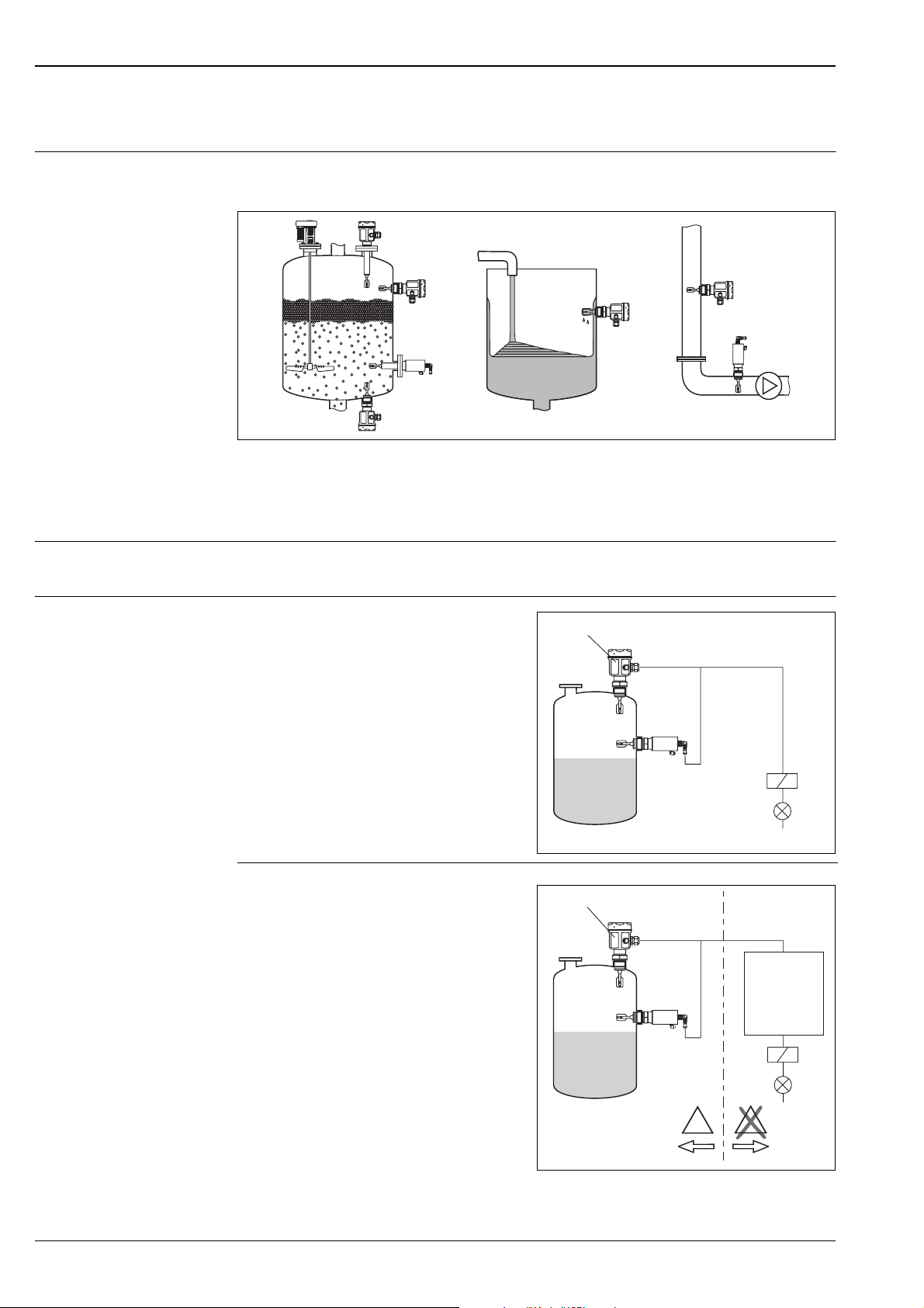
Level limit detection Maximum or minimum detection in tanks or pipes containing all kinds of liquids, including use in hazardous
areas, food and pharmaceuticals
L00-FTL5xxxx-11-05-xx-xx-000
Function and system design
Measuring principle The sensor's fork vibrates at its intrinsic frequency.
This frequency is reduced when covered with liquid. The change in frequency then activates a limit switch.
Modularity
Level limit switch
Liquiphant M FTL with electronic versions
FEL51, FEL52, FEL54
Level sensor
Liquiphant M FTL with electronic versions
FEL55, FEL56, FEL57, FEL58
for connecting to a separate switching unit or
or an isolating amplifier FEL50A
for connecting to PROFIBUS PA segment
FEL51/52/54
FEL55/56/57/58/50A
L00-FTL5xxxx-15-05-xx-xx-000
Ex i
Switching unit
PLC
Isolating
amplifier
Segment
coupler
…
E
X
…
E
X
L00-FTL5xxxx-15-05-xx-en-000
4 Endress+Hauser
Page 5

Liquiphant M FTL50(H), FTL51(H)
Electronic versions for level limit switches
Electronic versions for level sensor
FEL51:
Two-wire AC version;
Switch the load directly into the power supply circuit via the thyristor.
FEL52:
Three-wire DC version;
Switch the load via the transistor (PNP) and separate connection.
FEL54:
Universal current version with relay output;
Switch the loads via 2 floating change-over contacts.
FEL55:
For separate switching unit; signal transmission 16/8 mA along two-wire cabling.
FEL56:
For separate switching unit; signal transmission L-H edge 0.6…1.0 / 2.2…2.8 mA
to EN 50227 (NAMUR) along two-wire cabling.
FEL58:
For separate switching unit; signal transmission H-L edge 2.2…3.5 / 0.6…1.0 mA
to EN 50227 (NAMUR) along two-wire cabling.
Checking of connecting cabling and other devices by pressing a key on the electronic insert.
FEL57:
For separate switching unit; PFM signal transmission;
Current pulses superposed on the power supply along the two-wire cabling.
Cyclical checking from the switching unit without changing levels.
FEL50A:
For connecting to PROFIBUS PA;
Cyclic and acyclic data exchange acc. to PROFIBUS PA Profile 3.0 Discrete Input
Galvanic isolation FEL51, FEL52, FEL50A:
Between sensor and power supply
FEL54:
Between sensor and power supply and load
FEL55, FEL56, FEL57, FEL58:
See Switching unit connected
Design FTL50:
Compact
FTL51:
With extension pipe
FTL50H:
Compact, with polished tuning fork and hygienic process connections
FTL51H:
With extension pipe, polished tuning fork and hygienic process connections
Input
Measured variable Level (limit value)
Measuring range (detection range)
FTL50:
Depends on mounting point.
FTL51:
Depends on mounting point and the pipe extension. Standard 3000 mmm (up to 6000 mm on request)
3
Product density Adjustment on the electronic insert > 0.5 g/cm
or > 0.7 g/cm3 (other on request)
Endress+Hauser 5
Page 6
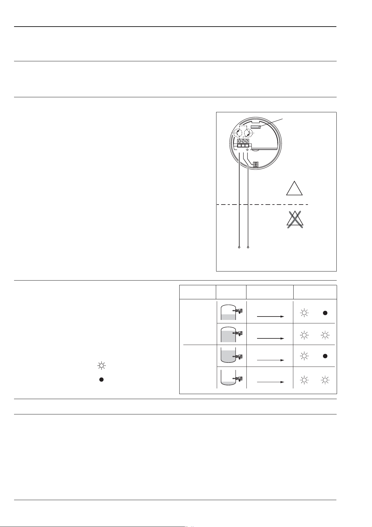
Electronic insert FEL51 (AC 2-wire)
Power supply Supply voltage: 19...253 V AC
Power consumption: < 0.83 W
Residual current consumption: < 3.8 mA
Short-circuit protection
FEM51 overvoltage protection: overvoltage category III
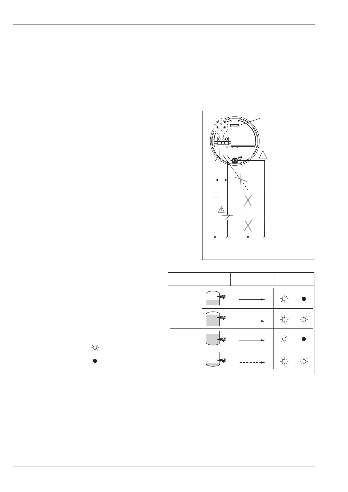
Electrical connection Two-wire AC connection
Always connect in series with a load!
Check the following:
• The residual current in blocked state
(up to 3.8 mA)
• that for low voltage
– the voltage drop across the load is such
that the minimum terminal voltage at the
electronic insert (19 V) when blocked is
not undershot.
– the voltage drop across the electronics when
switched through is observed
(up to 12 V)
• that a relay cannot de-energise with holding
power below 3.8 mA.
If this is the case, a resistor should be
connected parallel to the relay.
(RC module available on request).
• When selecting the relay, pay attention to
the holding power/rated power
(See "Connectable load")
12
min.
19 V
1A
*
R
L1
NNPE
U~ max. 253 V AC
50/60 Hz
Liquiphant M FTL50(H), FTL51(H)
FEL51
External load R
*
(Ground)
be connectedmust
L00-FTL5xxxx-04-05-xx-en-007
Output signal
Safety mode Level Output signal LEDs
green red
I
L
12
I
L
< 3.8 mA
L00-FTL2xxxx-07-05-
xx-xx-000
= load current
(switched through)
= residual current
(blocked)
= lit
= unlit
Max.
Min.
< 3.8 mA
12
I
L
12
< 3.8 mA
12
Signal on alarm Output signal on power failure or in the event of damaged sensor: < 3.8 mA
Connectable load • For relays with a minimum holding power/rated power > 2.5 VA at 253 V AC (10 mA) or
> 0.5 VA at 24 V AC (20 mA)
• Relays with a lower holding power/rated power can be operated by means of an RC module connected
inparallel
• For relays with a maximum holding power/rated power < 89 VA at 253 V AC or < 8.4 VA at 24 V AC
• Voltage drop across FEL51 max. 12 V
• Residual current with blocked thyristor max. 3.8 mA
• Load switched directly into the power supply circuit via the thyristor.
Transient (40 ms) max. 1.5 A, max. 375 VA at 253 V or max. 36 VA at 24 V (not short-circuit proof)
L00-FTL5xxxx-04-05-xx-xx-001
6 Endress+Hauser
Page 7
Liquiphant M FTL50(H), FTL51(H)
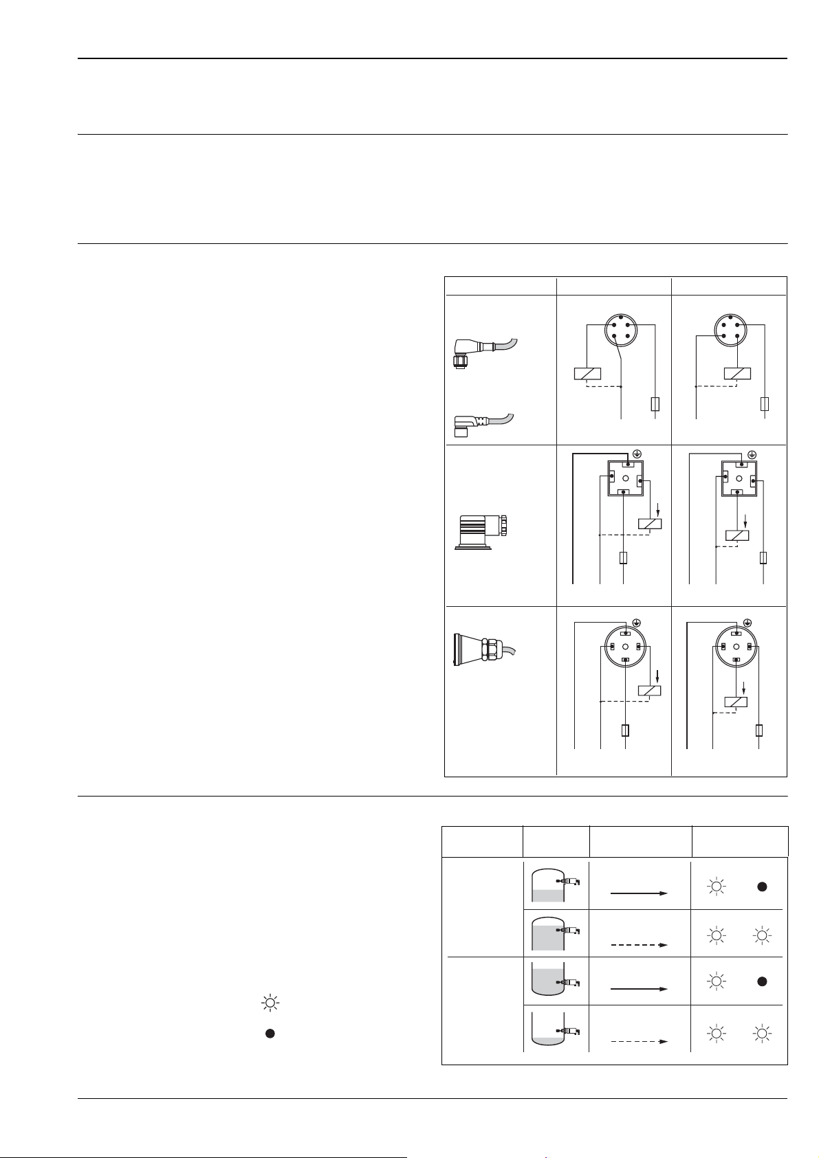
Electronics FEL51 (AC, in compact housing)
Power supply Supply voltage: 19...253 V AC
Power consumption: < 0.83 W
Residual current consumption: < 3.8 mA
Short-circuit protection
FEM51 overvoltage protection: overvoltage category III
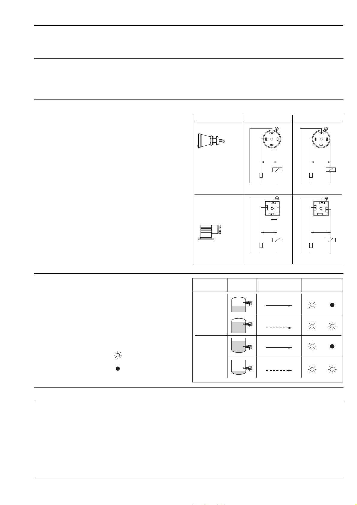
Electrical connection Two-wire AC connection
Always connect in series with a load!
Check the following:
• The residual current in
blocked state (up to 3.8 mA)
• that for low voltage
– the voltage drop across
the load is such that the
minimum terminal voltage
at the electronic insert
(19 V) when blocked is not
undershot.
– the voltage drop across
the electronics when switched
through is
observed (up to 12 V).
• That a relay
cannot de-energise with
holding power below 3.8 mA.
If this is the case, a resistor
should be connected parallel
to the relay.
(RC module available on request).
Connector
FTL5#(H)- #######C3#
FTL5#(H)- #######D3#
(Pg11)
or
FTL5#(H)- #######E3#
(NPT ½")
MAX MIN
(GN/YE) (GN/YE)
1
(BU)
3
(BN)
>19V
R
1.0 A
L1
1
>19V
1.0 A
L1
N
3
R
N
(Ground)
(Ground)
PE
(Ground)
PE
(Ground)
1
(BU)
L1
PE
1
L1
PE
L00-FTL5xxxx-04-05-xx-en-008
>19V
1.0 A
>19V
1.0 A
2
(BK)
R
N
2
R
N
Output signal
Safety mode Level Output signal LEDs
green red
I
L
13
I
L
< 3.8 mA
L00-FTL2xxxx-07-05-
xx-xx-000
= load current
(switched through)
= residual current
(blocked)
= lit
= unlit
Max.
Min.
< 3.8 mA
13
I
L
12
< 3.8 mA
12
Signal on alarm Output signal on power failure or in the event of damaged sensor: < 3.8 mA
Connectable load • For relays with a minimum holding power/rated power > 2.5 VA at 253 V AC (10 mA) or
> 0.5 VA at 24 V AC (20 mA)
• Relays with a lower holding power/rated power can be operated by means of an RC module connected
inparallel
• For relays with a maximum holding power/rated power < 89 VA at 253 V AC or < 8.4 VA at 24 V AC
• Voltage drop across FEL51 max. 12 V
• Residual current with blocked thyristor max. 3.8 mA
• Load switched directly into the power supply circuit via the thyristor.
Transient (40 ms) max. 1.5 A, max. 375 VA at 253 V or max. 36 VA at 24 V (not short-circuit proof)
L00-FTL5xxxx-04-05-xx-xx-001a
Endress+Hauser 7
Page 8
Electronic insert FEL52 (DC PNP)
Power supply Supply voltage: 10…55 V DC
Ripple: max. 1.7 V, 0…400 Hz
Current consumption: max. 15 mA
Power consumption: max. 0.83 W
Reverse polarity protection
Overvoltage protection FEL52: overvoltage category III
Electrical connection Three-wire DC connection
Preferably used with programmable
logic controllers (PLC).
DI module as per EN 61131-2.
Positive signal at switching output of
the electronics (PNP);
Output blocked on reaching limit.
Liquiphant M FTL50(H), FTL51(H)
FEL52
12 3
(+)
Output signal
I
L
< 100 μA
L00-FTL2xxxx-07-05-
xx-xx-000
= load current
(switched through)
= residual current
(blocked)
= lit
= unlit
0.5 A
e.g.
Relay
PLC
–
L–
L+
...
U– 10…55 V DC
Safety mode Level Output signal LEDs
green red
L+ +
I
L
13
Max.
< 100 µA
13
L+ +
I
L
13
Min.
< 100 µA
13
L00-FTL5xxxx-04-05-xx-en-001
L00-FTL5xxxx-04-05-xx-xx-004
Signal on alarm Output signal on power failure or in the event of damaged sensor: < 100 μA
Connectable load • Load switched via the transistor and separate PNP connection, max. 55 V DC
• Load current max. 350 mA (pulsed overload and short-circuit protection)
• Residual current < 100 μA (with transistor blocked)
• Capacitive load max. 0.5 μF at 55 V, max. 1.0 μF at 24 V
• Residual voltage < 3 V (with transistor switched through)
8 Endress+Hauser
Page 9
Liquiphant M FTL50(H), FTL51(H)
Electronics FEL52 (DC PNP, in compact housing)
Power supply Supply voltage: 10…55 V DC
Ripple: max. 1.7 V, 0…400 Hz
Current consumption: max. 15 mA
Power consumption: max. 0.83 W
Reverse polarity protection
Overvoltage protection FEL52: overvoltage category III
Electrical connection Three-wire DC connection
Preferably used with programmable
logic controllers (PLC).
DI module as per EN 61131-2.
Positive signal at switching
output of the electronics (PNP);
Output blocked on reaching limit.
Connector
FTL5#(H)- #######N3#
(M12x1)
52018763
FTL5#(H)- #######N3#
(M12x1)
52010285 / 52024216
MAX MIN
1
2
3
(BN)
4
(BK)
0.5 A
L– L+
(WT)
(BU)
R
1
2
(WT)
(BU)
L– L+
(BN)
3
4
(BK)
R
0.5 A
Output signal With valve connector or cable tail
FTL5#(H)- #######D3#
(Pg11)
or
FTL5#(H)- #######E3#
(NPT ½")
FTL5#(H)- #######C3#
L– L–L+ L+
PE PE
(Ground) (Ground)
(GN/YE)
1
(BU)
3
(BN)
L– L–L+ L+
PE PE
(Ground) (Ground)
R
0.5 A
R
0.5 A
2
(BK)
+
–
(GN/YE)
1
(BU)
+
–
Safety mode Level Output signal LEDs
green red
11
R
(BN)
R
L00-FTL5xxxx-04-05-xx-en-010
0.5 A
3
0.5 A
22
33
+
–
2
(BK)
+
–
L+ +
I
L
32
I
L
< 100 μA
L00-FTL2xxxx-07-05-
xx-xx-000
= load current
(switched through)
= residual current
(blocked)
= lit
= unlit
Max.
Min.
L+ +
< 100 µA
32
L+ +
I
L
23
L+ +
< 100 µA
23
L00-FTL5xxxx-04-05-xx-xx-004a
Endress+Hauser 9
Page 10
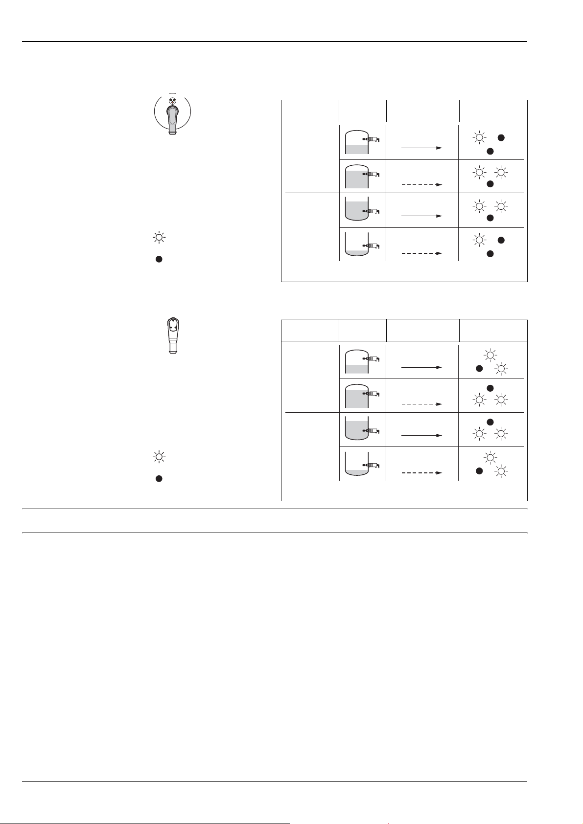
With M12x1 connector 52010285 / 52024216 (without LEDs)
gn
ye
rd
Safety mode Level Output signal LEDs
Liquiphant M FTL50(H), FTL51(H)
L00-FTL5xxxx-16-05-
xx-xx-002
Max.
I
L
< 100 μA
= load current
(switched through)
= residual current
(blocked)
= lit
Min.
= unlit
L00-FTL2xxxx-07-05-
xx-xx-000
With M12x1 connector 52018763 (with LEDs)
ye 1
ye 2
L00-FTL5xxxx-16-05-
xx-xx-001
gn
Safety mode Level Output signal LEDs
Max.
I
L
< 100 μA
= load current
(switched through)
= residual current
(blocked)
= lit
Min.
= unlit
L00-FTL2xxxx-07-05-
xx-xx-000
L+ –
I
L
12
L+ –
< 100 µA
12
L+ –
I
L
14
L+ –
< 100 µA
14
L00-FTL5xxxx-04-05-xx-xx-010
L+ –
I
L
12
L+ –
< 100 µA
12
L+ –
I
L
14
L+ –
< 100 µA
14
L00-FTL5xxxx-04-05-xx-xx-011
Signal on alarm Output signal on power failure or in the event of damaged sensor: < 100 μA
Connectable load • Load switched via the transistor and separate PNP connection, max. 55 V DC
• Load current max. 350 mA (pulsed overload and short-circuit protection)
• Residual current < 100 μA (with transistor blocked)
• Capacitive load max. 0.5 μF at 55 V, max. 1.0 μF at 24 V
• Residual voltage < 3 V (with transistor switched through)
10 Endress+Hauser
Page 11
Liquiphant M FTL50(H), FTL51(H)
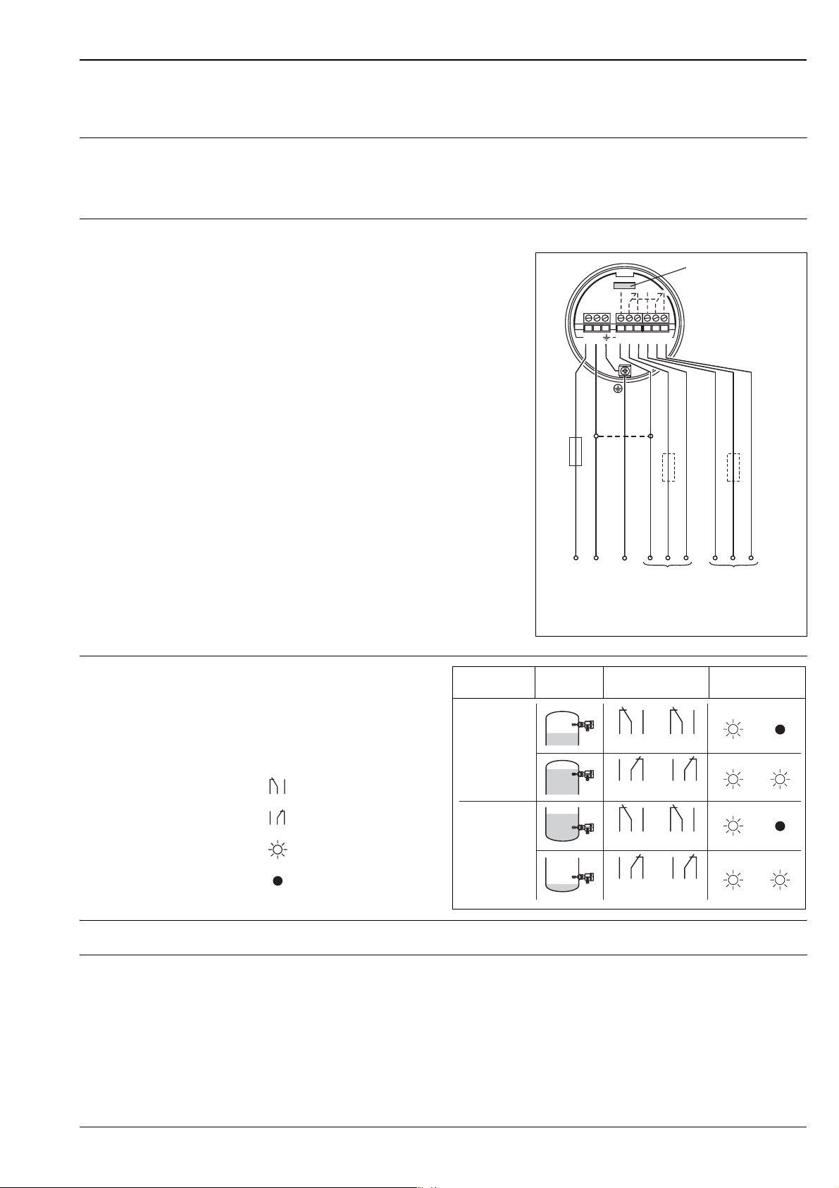
Electronic insert FEL54 (AC/DC with relay output)
Power supply Supply voltage: 19…253 V AC, 50/60 Hz or 19…55 V DC
Power consumption: max. 1.3 W
Reverse polarity protection
Overvoltage protection FEL54: overvoltage category III
Electrical connection Universal current connection with relay output
Power supply:
Please note the different voltage ranges
for AC and DC.
Output:
When connecting an instrument with
high inductance, provide a spark arrester
to protect the relay contact.
A fine-wire fuse (depending on the
load connected) protects the relay
contact on short-circuiting.
Both relay contacts switch simultaneously.
* When jumpered, the relay
output works with NPN logic.
0.5 A
FEL54
12 678345
*
Output signal
** See below "Connectable load"
= relay energised
= relay de-energised
= lit
= unlit
L00-FTL2xxxx-07-05-
xx-xx-001
NC
NO
C
a
u
N
L1
L+
U~ 19…253 V AC, 50/60 Hz
U– 19… 55 V DC
PE
(Ground)
L–
...
** **
NO
r
a
Safety mode Level Output signal LEDs
green red
Max.
Min.
354
354
354
354
687
687
687
687
L00-FTL5xxxx-04-05-xx-xx-005
NC
C
r
u
L00-FTL5xxxx-04-05-xx-xx-002
Signal on alarm Output signal on power failure or in the event of damaged sensor: relay de-energised
Connectable load • Loads switched via 2 floating change-over contacts (DPDT)
• I~ max. 6 A (EEx d 4 A), U~ max. 253 V AC; P~ max. 1500 VA, cos ϕ = 1, P~ max. 750 VA, cos ϕ > 0.7
•I% max. 6 A (EEx d 4 A) to 30 V, I% max. 0.2 A to 125 V
• When connecting a low-voltage circuit with double isolation according to IEC 1010 the following applies:
total of voltages of relay output and power supply max. 300 V
Endress+Hauser 11
Page 12
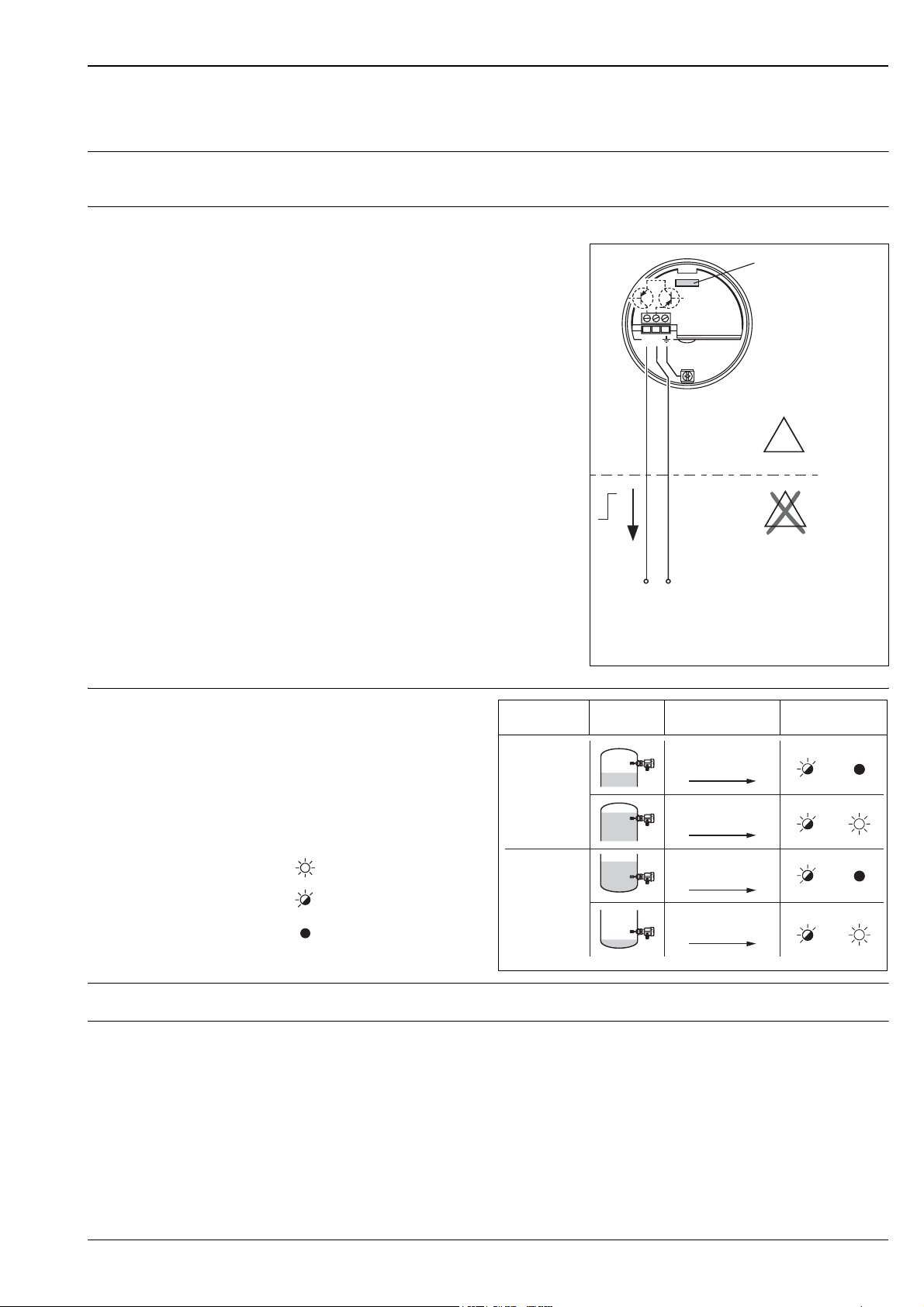
Electronic insert FEL55 (8/16 mA)
1 2
FEL55
–
EEx ia
+
E
X
E
X
U– 1
1…36 V DC
...
e.g. PLC
Power supply Supply voltage: 11...36 V DC
Power consumption: < 600 mW
Reverse polarity protection
Overvoltage protection FEL55: overvoltage category III
Electrical connection Two-wire connection for separate switching unit
For connecting to programmable
logic controllers (PLC).
AI module 4...20 mA to EN 61131-2.
Output signal jump from high to low
current on limit.
EEx ia
Liquiphant M FTL50(H), FTL51(H)
FEL55
12
X
E
Output signal
~ 16 mA
~8 mA
L00-FTL2xxxx-07-05-
xx-xx-000
= 16 mA ± 5 %
= 8 mA ± 6 %
= lit
= unlit
E
X
–
+
...
U– 1
1…36 V DC
e.g. PLC
L00-FTL5xxxx-04-05-xx-en-000
Safety mode Level Output signal LEDs
green red
+
~16 mA
21
Max.
+
~8 mA
21
+
~16 mA
21
Min.
+
~8 mA
21
L00-FTL5xxxx-04-05-xx-xx-006
Signal on alarm Output signal on power failure or in the event of damaged sensor: < 3.6 mA
Connectable load • R = (U - 11 V) : 16.8 mA
• U = connection voltage: 11…36 V DC
Example:
PLC with 250 Ω loop powered input
250 Ω = (U – 11V) / 16, 8 mA
4,2 [Ω/Α] = U – 11 V
U = 15,2 V
12 Endress+Hauser
Page 13
Liquiphant M FTL50(H), FTL51(H)
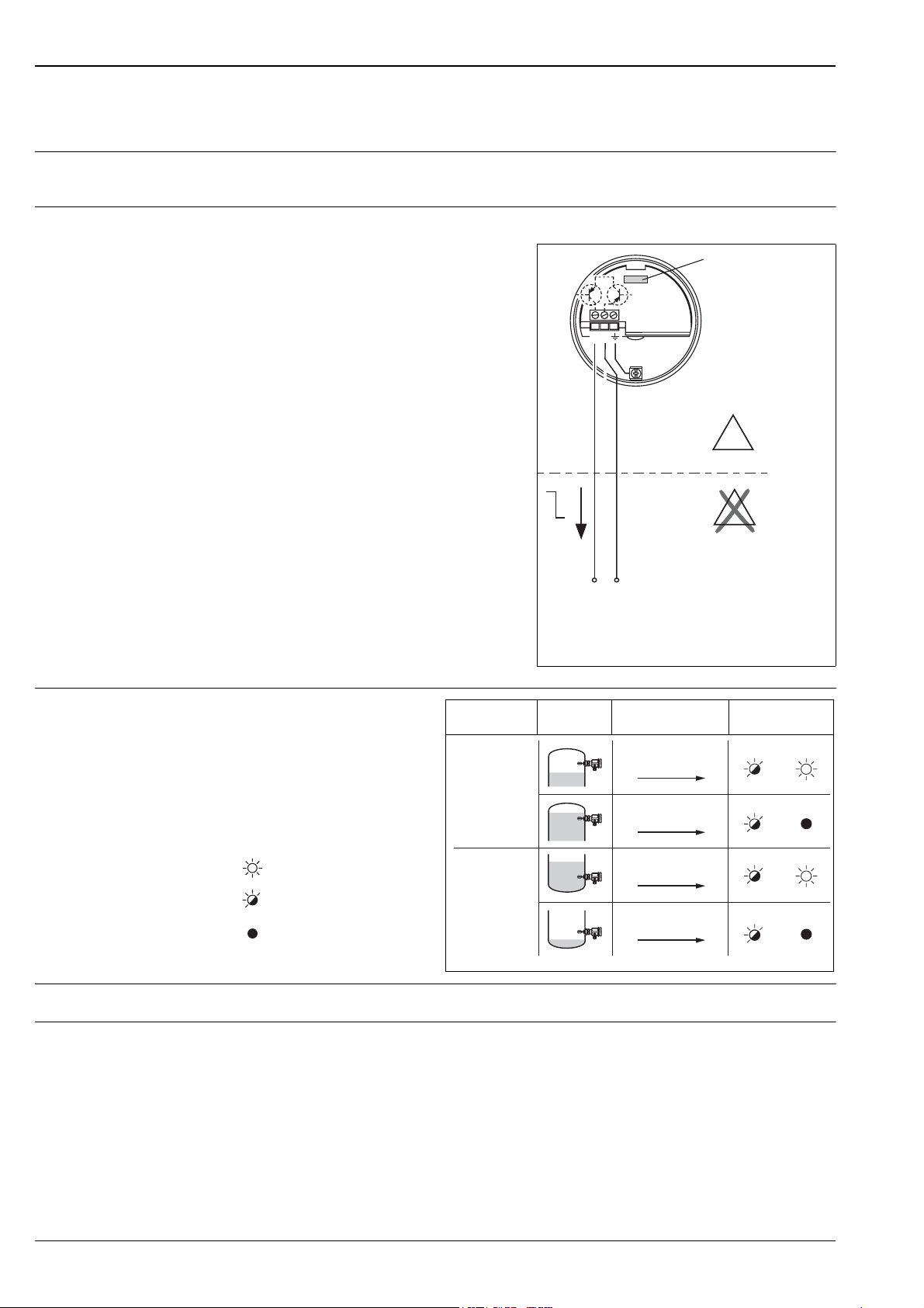
Electronic insert FEL56 (NAMUR L-H edge)
Power supply Power consumption: < 6 mW bei I < 1 mA; < 38 mW bei I = 2,2...4 mA
Connection data interface: IEC 60947-5-6
Electrical connection Two-wire connection for separate switching unit
For connecting to isolating amplifiers
acc. to NAMUR (IEC 60947-5-6),
e.g. FXN421, FXN422, FTL325N,
FTL375N or Commutec SIN100,
SIN110 from Endress+Hauser.
Output signal jump from low
to high current on limit.
(L-H edge)
12
FEL56
Output signal
Connecting to multiplexer:
Set clock time to min. 2 s.
EEx ia
X
E
H
I
L
–
+
Isolating amplifier
to
IEC 60947-5-6
(NAMUR)
E
X
Safety mode Level Output signal LEDs
green red
0.6 …
+
1.0 mA
Max.
21
2.2 …
+
2.8 mA
21
L00-FTL5xxxx-04-05-xx-en-004
L00-FTL5xxxx-07-05-
xx-xx-002
= lit
= flashes
= unlit
Min.
0.6 …
+
1.0 mA
21
2.2 …
+
2.8 mA
21
L00-FTL5xxxx-04-05-xx-xx-003
Signal on alarm Output signal in the event of damaged sensor: > 2.2 mA
Connectable load • See Technical Data of isolating amplifier connected according to IEC 60947-5-6 (NAMUR)
Endress+Hauser 13
Page 14
Liquiphant M FTL50(H), FTL51(H)
Electronic insert FEL58 (NAMUR H-L edge)
Power supply Power consumption: < 6 mW bei I < 1 mA; < 38 mW bei I = 2,2...4 mA
Connection data interface: IEC 60947-5-6
Electrical connection Two-wire connection for separate switching unit
For connecting to isolating amplifiers
acc. to NAMUR (IEC 60947-5-6),
e.g. FXN421, FXN422, FTL325N,
FTL375N or Commutec SIN100,
SIN110 from Endress+Hauser.
Output signal jump from high
to low current on limit.
(H-L edge)
12
FEL58
Output signal
Additional function:
Test key on the electronic insert.
Pressing the key breaks the connection
to the isolating amplifier.
Note!
!
For Ex-d applications, the additional function
can only be used if the housing is not exposed
to an explosive atmosphere.
Connecting to multiplexer:
Set clock time to min. 2 s.
Safety mode Level Output signal LEDs
Max.
EEx ia
H
I
L
–
+
Isolating amplifier
to
IEC 60947-5-6
(NAMUR)
2.2 …
+
3.5 mA
21
0.6 …
+
1.0 mA
21
X
E
E
X
L00-FTL5xxxx-04-05-xx-en-002
green yellow
2.2 …
+
3.5 mA
21
0.6 …
+
1.0 mA
21
L00-FTL5xxxx-04-05-xx-xx-007
L00-FTL5xxxx-07-05-
xx-xx-002
= lit
= flashes
= unlit
Min.
Signal on alarm Output signal in the event of damaged sensor: < 1.0 mA
Connectable load • See Technical Data of isolating amplifier connected according to IEC 60947-5-6 (NAMUR)
• Connection also to isolating amplifiers which have special safety circuits (I > 3.0 mA)
14 Endress+Hauser
Page 15
Liquiphant M FTL50(H), FTL51(H)
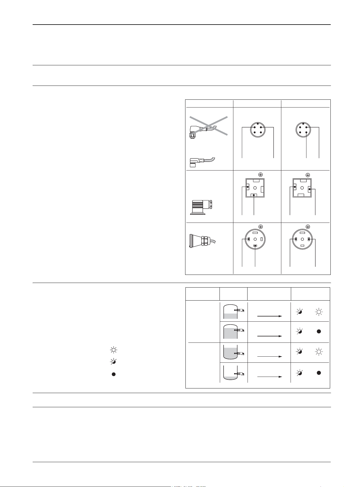
Electronics FEL58 (NAMUR H-L edge, in compact housing)
Power supply Power consumption: < 6 mW bei I < 1 mA; < 38 mW bei I = 2,2...4 mA
Connection data interface: IEC 60947-5-6
Electrical connection Two-wire connection for separate switching unit
For connecting to isolating
amplifiers acc. to
NAMUR (IEC 60947-5-6),
e.g. FXN421, FXN422,
FTL325N, FTL375N
or Commutec SIN100,
SIN110 from Endress+Hauser.
Output signal jump from high
to low current on limit.
(H-L edge)
Connector
FTL5#(H)- #######N3#
(M12x1)
52018763
FTL5#(H)- #######N3#
(M12x1)
52010285 / 52024216
MAX MIN
2
(WT)
3
(BU)
–
1
(BN)
4
(BK)
1
2
3
(BN)
4
(BK)
–+
(WT)
(BU)
+
Output signal
Additional function:
If the test magnet is held
against the marking on the
nameplate, the output signal
is inverted.
Connecting to multiplexer:
Set clock time to min. 3 s.
The NAMUR interface has
a defined power consumption.
Thus, it is not possible to use
the M12 connector with
integrated LED (52018763).
FTL5#(H)- #######D3#
(Pg11)
or
FTL5#(H)- #######E3#
(NPT ½")
FTL5#(H)- #######C3#
(BU)
1
3
–
+
1
3
(BN)
+
–
(BU)
1
+
1
+
Safety mode Level Output signal LEDs
green yellow
2.2…
+–
3.5 mA
13
Max.
0.6…
+–
1.0 mA
13
2
–
2
(BK)
–
L00-FTL5xxxx-04-05-xx-en-009
2.2…
+–
3.5 mA
12
0.6…
+–
1.0 mA
12
L00-FTL5xxxx-04-05-xx-xx-007a
L00-FTL5xxxx-07-05-
xx-xx-002
= lit
= flashes
= unlit
Min.
Signal on alarm Output signal in the event of damaged sensor: < 1.0 mA
Connectable load • See Technical Data of isolating amplifier connected according to IEC 60947-5-6 (NAMUR)
• Connection also to isolating amplifiers which have special safety circuits (I > 3.0 mA)
Endress+Hauser 15
Page 16
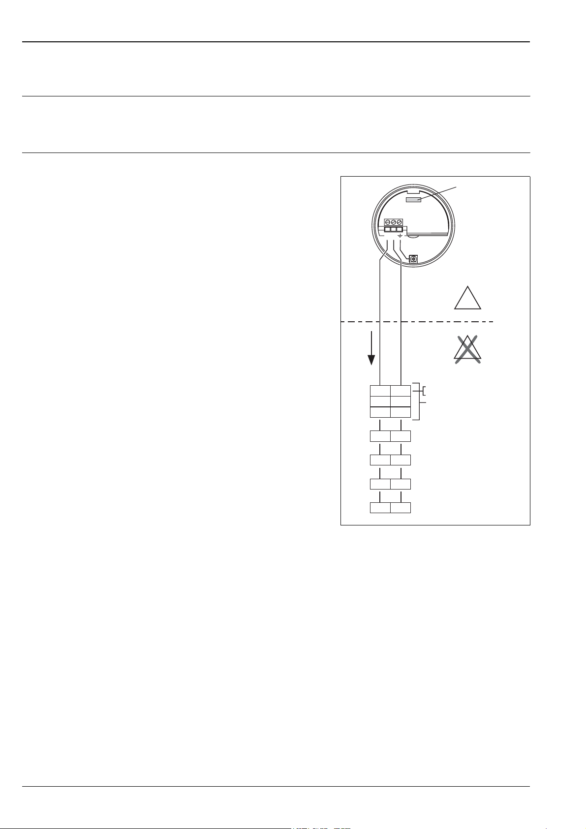
Electronic insert FEL57 (PFM)
Power supply Supply voltage: 9,5...12,5 V DC
Current consumption: 10...13 mA
Power consumption: < 150 mW
Reverse polarity protection
Electrical connection Two-wire connection for separate switching unit
For connecting to switching units
Nivotester FTL320, FTL325P,
FTL370, FTL372, FTL375P
(also with cyclical checking)
Commutec SIF101, SIN111
from Endress+Hauser.
Output signal jump of PFM signal
from high to low frequency
when sensor is covered.
Switching between minimum/maximum
safety in the Nivotester.
Additional function "cyclical checking":
After interruption of the power supply,
a test cycle is activated which checks
the sensor and electronics without any
change in level.
Approved for overfill protection acc. to WHG,
Germany.
The following can be switched at the
electronic insert:
– Standard (STD):
for low corrosive liquids;
simulation approx. 8 s
tuning fork exposed – covered – exposed.
– Extended (EXT):
for highly corrosive liquids;
simulation approx. 41 s
tuning fork exposed – covered – corroded –
exposed.
The check is activated and monitored at the
switching unit.
EEx ia
PFM
50 /
150 Hz
Liquiphant M FTL50(H), FTL51(H)
FEL57
12
X
E
E
X
–+
78
33 34
37 38
d4 d2
z4 z2
z6 d6
21
Nivotester
FTL320
FTL325P 1CH
FTL325P 3CH
FTL370/372
FTL375P 1CH
Input 1
FTL372
FTL375P 2CH
Input 2
FTL375P 3CH
Input 3
Commutec S
SIF101, SIF111
L00-FTL5xxxx-04-05-xx-en-003
16 Endress+Hauser
Page 17
Liquiphant M FTL50(H), FTL51(H)
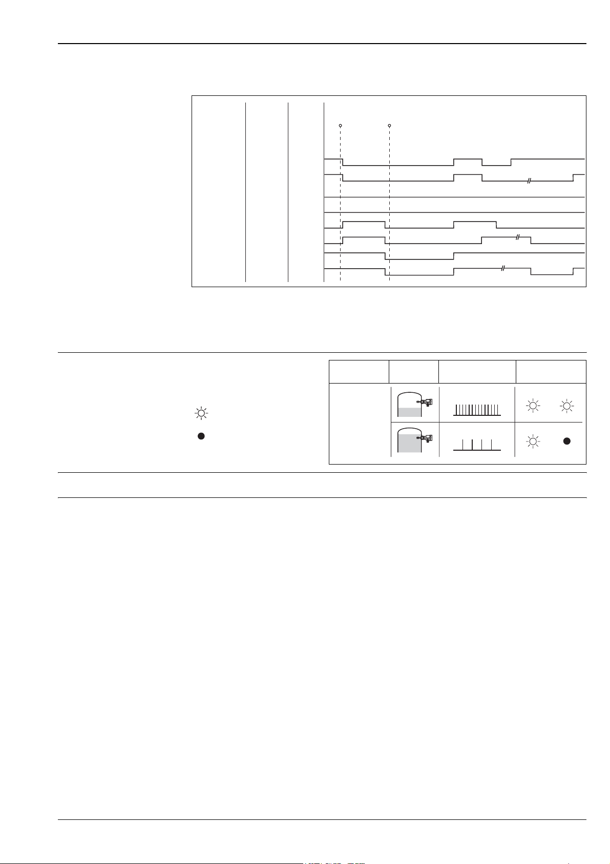
Switching behaviour of the connected device:
Output signal
Fail-safe mode
set at
switching unit
Max.
Max.
Max.
Max.
Min.
Min.
Min.
Min.
Setting
at FEL57
STD
EXT
STD
EXT
STD
EXT
STD
EXT
Fork
free
free
covered
covered
free
free
covered
covered
Switching status of relay in switching unit
on = energised off = de-energised
Test start End of test start
(power off) (power on)
>3s
on
on
off
off
off
off
on
on
off
off
off
off
~3son
~3son
~3son
~3son
~5soff
~5soff
off
off
~5soff
*
~7soff
*
~5soff
*
~5soff
*
~2son
~2son
~3son
on
~35son
~2soff
~35soff
off
~30son
on
off
~3soff
L00-FTL5xxxx-05-05-xx-en-000
on
on
* De-energised on power supply failure
Please note this switching response and function of the plant, especially when replacing a Liquiphant with an
EL17Z or FEL37 electronic insert by a Liquiphant M with the FEL57 electronic insert.
Safety mode Level Output signal
(PFM)
150 Hz
LEDs
green yellow
= lit
50 Hz
L00-FTL5xxxx-04-05-xx-xx-008
L00-FTL2xxxx-07-05-
xx-xx-000
= unlit
Signal on alarm Output signal on power failure or in the event of damaged sensor: 0 Hz
Connectable load • Floating relay contacts in the connected switching unit Nivotester FTL320, FTL325P, FTL370, FTL372,
FTL375P or Commutec SIF101, SIF111
• For contact load see the Technical Data of the switching unit
Endress+Hauser 17
Page 18
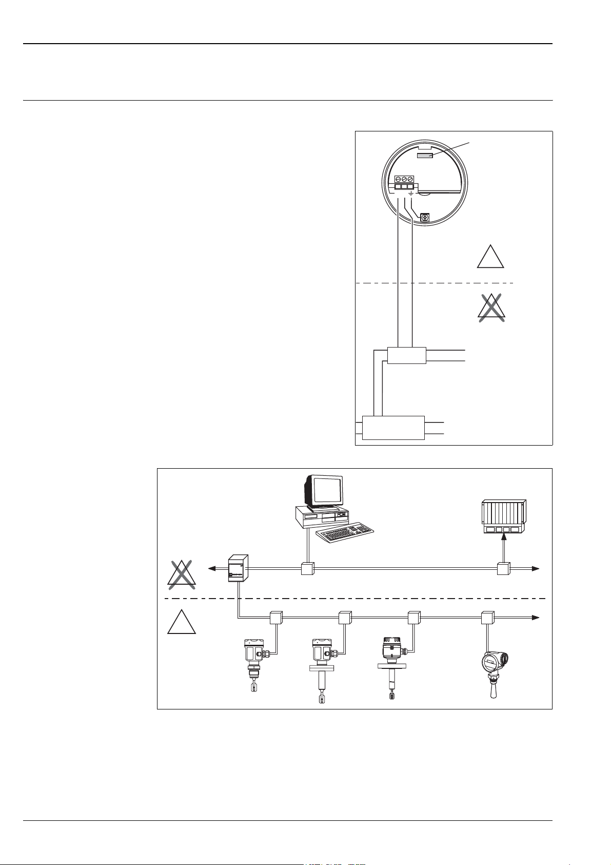
Electronic insert FEL50A (PROFIBUS PA)
Electrical connection Two-wire connection for power supply and data transfer
Liquiphant M FTL50(H), FTL51(H)
For connecting to PROFIBUS PA
Additional functions:
– Digital communication enables the
representation, reading and editing
of the following parameters:
Fork frequency, switch-on frequency,
switch-off frequency, switch-on time and
switch-off time, status, measured value,
density switch.
– Matrix locking possible
– Switch to WHG mode possible
(WHG approval).
– For a detailed description see BA198F
– You can also visit
www.profibus.com for more information
12
PA– PA +
...
U– 9…32 V DC
Segment coupler
FEL50A
–
–
PROFIBUS PA
–
–
X
E
E
X
L00-FTL5xxxx-04-05-xx-en-005
PC with Commuwin II
Proficard or Profiboard
Segment coupler
PROFIBUS DP
X
E
PROFIBUS PA
E
X
PLC
L00-FTL5xxxx-04-05-xx-en-006
18 Endress+Hauser
Page 19
Liquiphant M FTL50(H), FTL51(H)
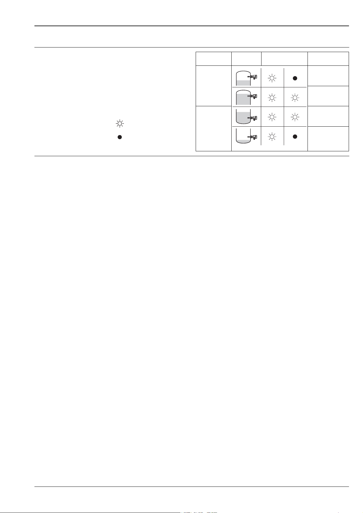
Output signal
Setting Level LEDs
not
inverted
= lit inverted
= unlit
L00-FTL2xxxx-07-05-
xx-xx-000
Signal on alarm • Failure information can be opened using the following interfaces:
Yellow LED flashing, status code, diagnostic code; see BA198F
FEL50A
green yellow
OUT_D = 0
PA bus signal
OUT_D = 1
PA bus signal
OUT_D = 1
PA bus signal
OUT_D = 0
PA bus signal
L00-FTL5xxxx-04-05-xx-xx-009
Endress+Hauser 19
Page 20
Connection and function
Liquiphant M FTL50(H), FTL51(H)
Connecting cables • Electronic inserts: cross-section max. 2.5 mm2; strand in ferrule to DIN 46228
• Protective earth in housing: cross-section max. 2.5 mm
2
• External equipotential bonding connection on housing: cross-section max. 4 mm
Fail-safe mode Minimum/maximum residual current safety selectable on electronic insert
(with FEL57 on Nivotester only)
Max. = maximum safety:
The output switches to the power fail response when the fork is covered
For use with overfill protection for example
Max. = minimum safety:
The output switches to the power fail response when the fork is exposed
For use with dry running protection for example
Switching time When fork is covered: approx. 0.5 s
When fork is exposed: approx. 1.0 s
Other switching times on request
Additionally configurable for PROFIBUS PA: 0.5...60 s
Switch-on behaviour When switching on the power supply, the output assumes the alarm signal.
After max. 3 s it assumes the correct switching mode (Exception: FEL57)
Performance characteristics
2
Reference operating conditions
Ambient temperature: 23 °C
Medium temperature: 23 °C
Product density: 1 g/cm
3
(water)
Viscosity: 1 mm2/s
Medium pressure p
: 0 bar
e
Sensor mounting: vertical from above
Density switch: to > 0.7
Maximum measured error Specified by mounting position: max. +/–1 mm
Repeatability 0.1 mm
Hysteresis Approx. 2 mm
Influence of medium
Max. +1.8…–2.8 mm (–50…+150 °C)
temperature
3
Influence of product density Max. +4.8…–3.5 mm (0.5…1.5 g/cm
)
Influence of medium pressure Max. 0…–2.5 mm (–1…64 bar)
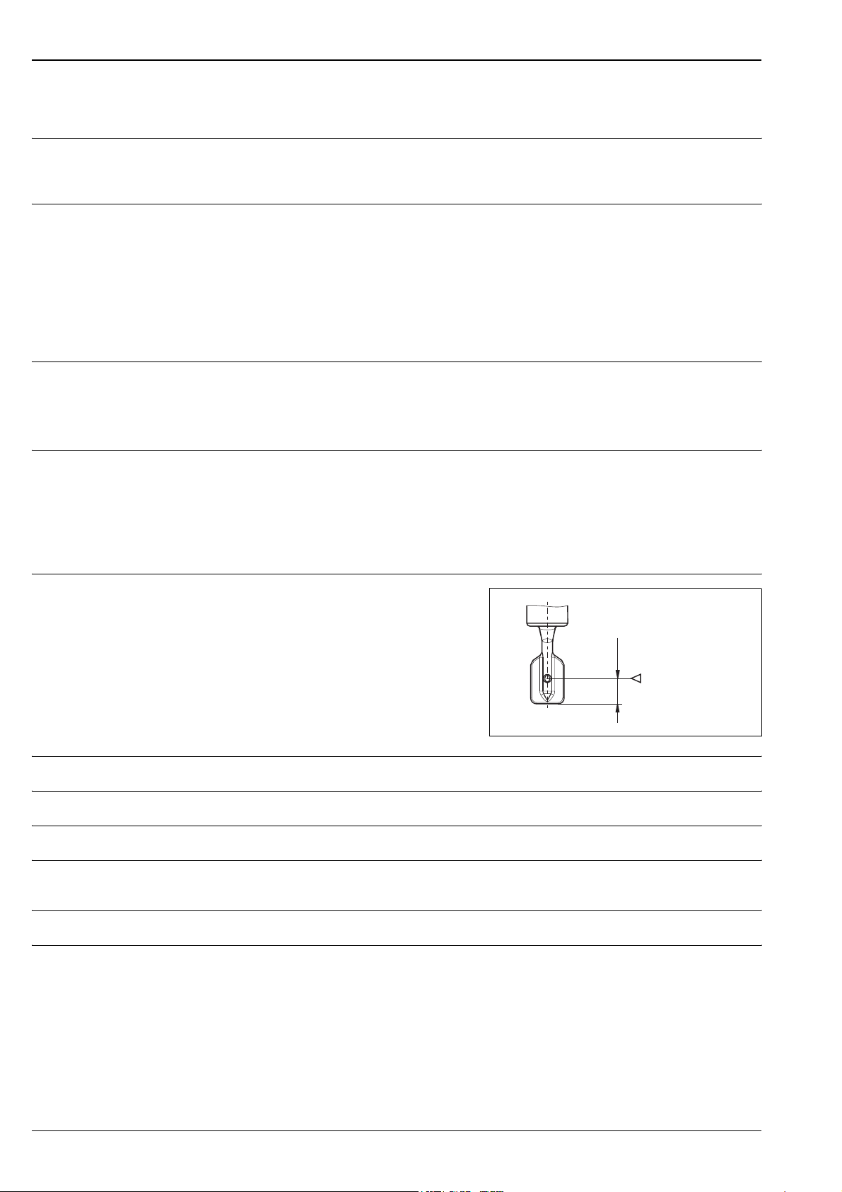
Switchpoint
for
reference conditions
13 mm
L00-FTL5xxxx-06-05-xx-en-000
20 Endress+Hauser
Page 21
Liquiphant M FTL50(H), FTL51(H)
Operating conditions
Installation Installation instructions
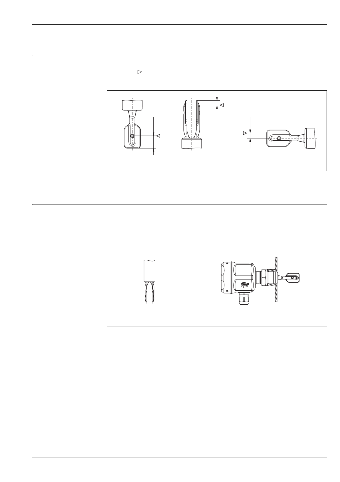
Switch points on the sensor depend on the mounting position, with reference to water,
3
density 1 g/cm
, 23 °C, pe 0 bar.
4mm
13 mm
Mounting from above Mounting from below Mounting from the side
!
Examples of mounting Examples of mounting with regard to the viscosity ν of the liquid and the amount of build-up
Note!
The switchpoints of the Liquiphant M are at other positions to those of the previous version Liquiphant II.
Optimum mounting, without problem even with high viscosity:
Position the fork so that the narrow edge of the tines is vertical.
This ensures that the liquid can run off easily.
4mm
L00-FTL5xxxx-06-05-xx-xx-001
L00-FTL5xxxx-11-05-xx-xx-001
Vertical from above Flush-mounted from the side
Endress+Hauser 21
Page 22
Liquiphant M FTL50(H), FTL51(H)
With build-up on the tank walls:
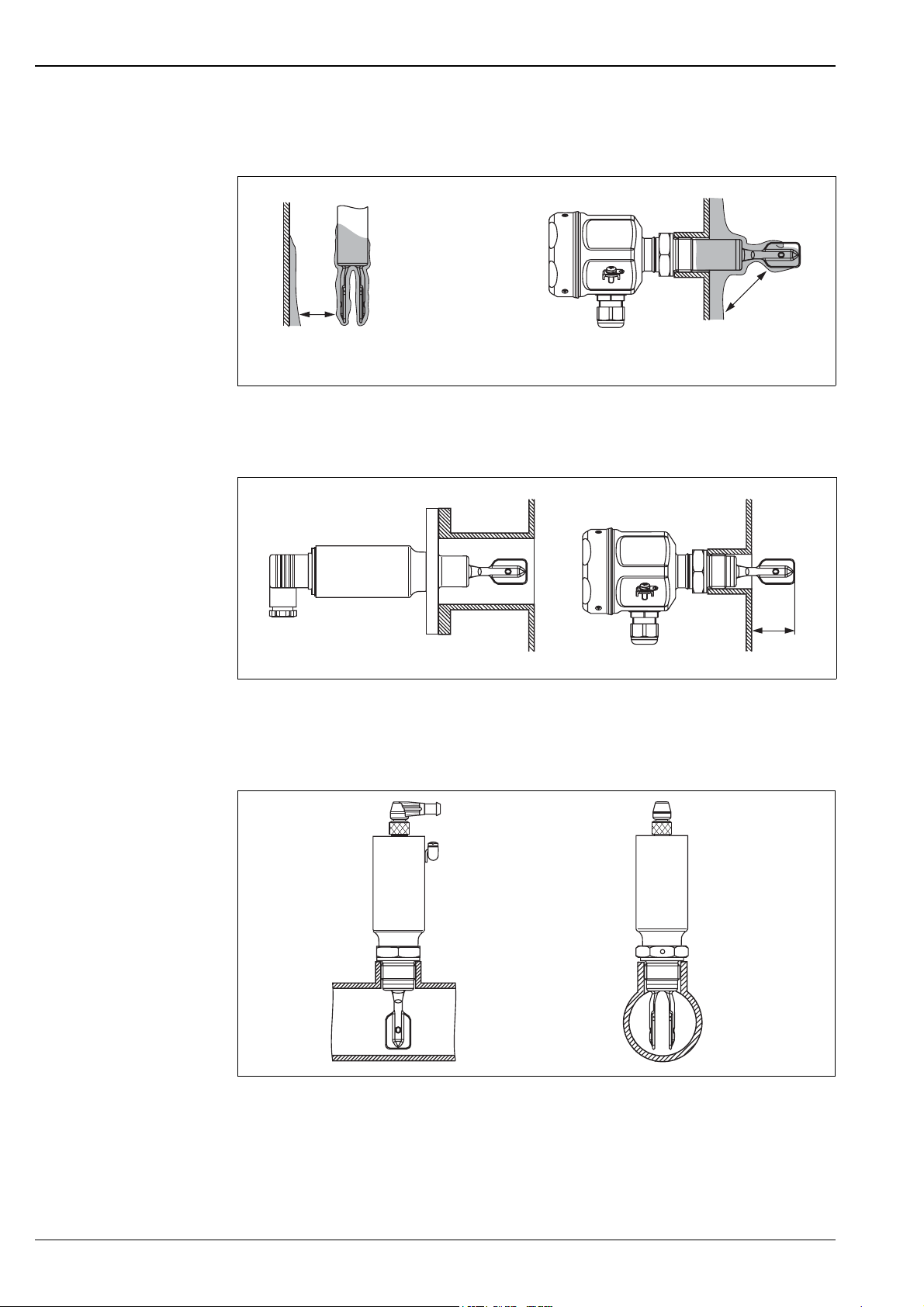
* Ensure that there is sufficient distance between the build-up expected on the tank wall and the fork.
*
*
L00-FTL5xxxx-11-05-xx-xx-002
Vertical from above Protruding into the tank from the side
2
Mounting positions with low viscosity (up to 2000 mm
* Deburr the nozzle surfaces
/s):
*
Mounting in piping from 2"
Fluid velocities up to 5 m/s for viscosity 1 mm2/s and density 1 g/cm3.
(Check the function for other operating conditions.)
*
min. 25
(min. 1 in)
L00-FTL5xxxx-11-05-xx-en-003
L00-FTL5xxxx-11-05-xx-xx-004
22 Endress+Hauser
Page 23
Liquiphant M FTL50(H), FTL51(H)
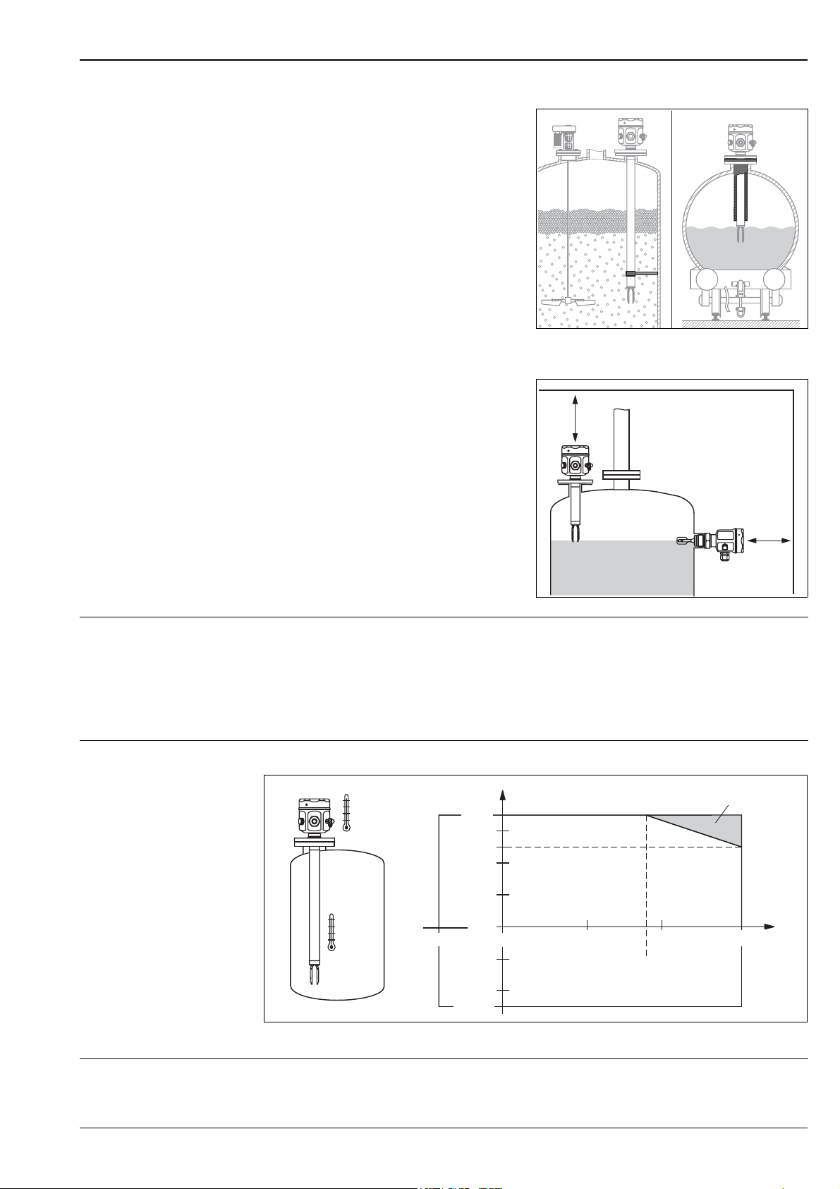
Support the Liquiphant M FTL51(H)
in the event of high dynamic loads.
L00-FTL5xxxx-11-05-xx-xx-005
.. .. .. .. .. .. .. .. .. .. .. .. .. .. .. .. .. .. .. .. .. ..
...........................................
Ensure adequate space outside the tank
.. .. .. .. .. .. .. .. .. .. .. .. .. .. .. .. .. .. .. .. .. .
...........................................
for mounting, electrical connection and
configuration.
L00-FTL5xxxx-11-05-xx-xx-006
Orientation FTL50(H) and FTL51(H) with short pipe (up to approx. 500 mm) – any position,
FTL51(H) with long pipe – vertical
Environment
Ambient temperature range Permitted ambient temperature Ta at the housing depending on the medium temperature Tp in the tank:
.. .. .. .. .. .. .. .. .. .. .. .. .. .. .. .. .. .. .
.. .. .. .. .. .. .. .. .. .. .. .. .. .. .. .. .. ..
.. .. .. .. .. .. .. .. .. .. .. .. .. .. .. .. .. .
.. .. .. .. .. .. .. .. .. .. .. .. .. .. .. .. ..
T
a
T
a
T
p
–50 °C
70 °C
50 °C
0°C
0°C 50°C
–50 °C
100 °C 150 °C
90 °C
*
T
p
L00-FTL5xxxx-05-05-xx-xx-001
* Additional temperature range for devices with a temperature spacer or flameproof bushing
Ambient temperature limits –50…+70 °C (function with restricted data)
Endress+Hauser 23
Page 24
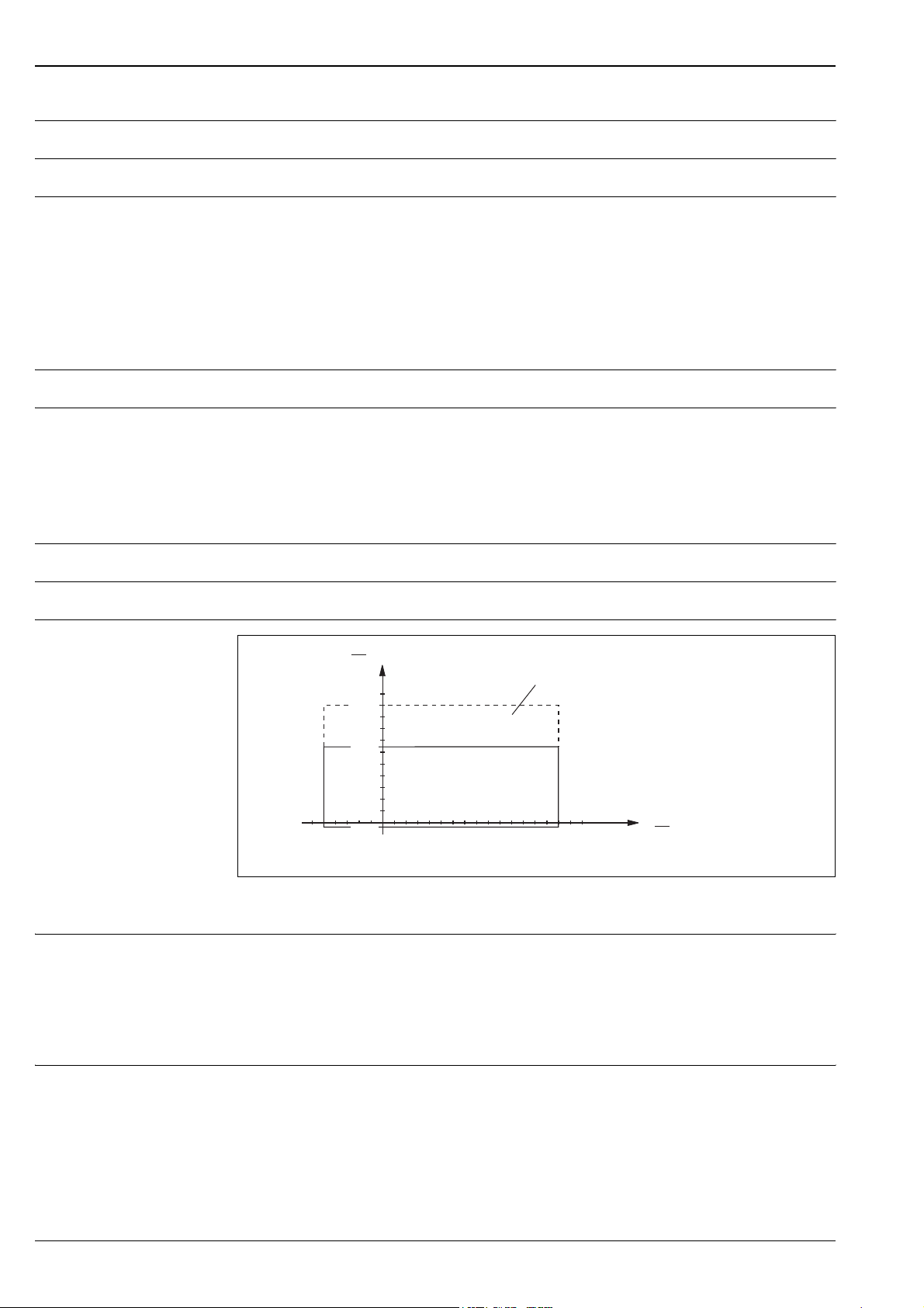
Storage temperature –50…+80 °C
*
p
e
bar
si)
T
p
°C
(°F)
64
(928)
–50
(–58)
150
(300)
0
(32)
–1
(–14.5)
100
(1450)
Climate class Climate protection to IEC 68, Part 2-38, Fig. 2a
Degree of protection • Polyester, steel and aluminium housings: IP66/IP67 to EN 60529
• Aluminium housing (EEx d, EEx de): IP66/IP68 to EN 60529 (1 m, 24 h)
• Compact housing:
– IP65 with valve connector Pg11/NPT ½
– IP66/68 with 5m cable tail
– IP66/68 with M12x1 connector (52010285) 316L (metal);
– IP69k with connector (52024216), elbowed / L= 5 m, without build-in LEDs
– IP69k with connector (52018763), elbowed / L= 5 m, with build-in LEDs
Vibration resistance To IEC 68, Part 2-6 (10…55 Hz, 0.15 mm, 100 cycles)
Electromagnetic compatibility Interference emission to EN 61326, Electrical Equipment Class B
Interference immunity to EN 61326; Annex A (Industrial) and NAMUR Recommendation NE 21 (EMC)
Liquiphant M FTL50(H), FTL51(H)
Medium conditions
Medium temperature range –50…+150 °C; for exceptions, see "Process connections"
Thermal shock Max. 120 °C/s
Medium pressure p
Test pressure pe = 64 bar:
e
(–58)
–50
p
e
bar
(p(psi)
100
(1450)
(928)
(–14.5)
64
–1
0
(32)
* Allowed pressure rating by selecting the "100 bar" option (see "Product structure" code 060)
Exceptions see "Process connections"
max. 100 bar (1.5 times the medium pressure p
); no function during test pressure
e
Burst pressure of diaphragm 200 bar
pe = 100 bar:
max. 150 bar (1.5 times the medium pressure p
); no function during test pressure
e
Burst pressure of diaphragm 400 bar
*
150
(300)
T
°C
(°F)
p
L00-FTL5xxxx-05-05-xx-xx-003
State of aggregation Liquid
24 Endress+Hauser
Page 25
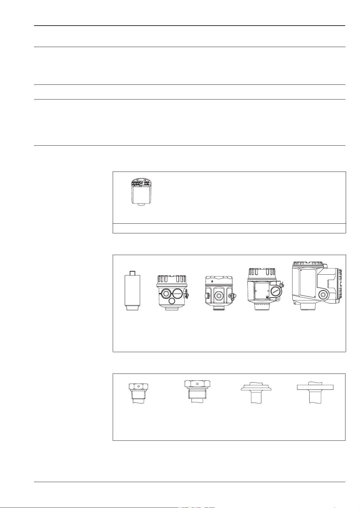
Liquiphant M FTL50(H), FTL51(H)
Density 0.7 g/cm3 = delivery status
0.5 g/cm3* adjustable over switches
* Density settings for the compact housing on request
2
Viscosity Max. 10000 mm
/s
Solids content Max. ø5 mm
Mechanical construction
Design Summary of all electrical and mechanical versions
Plug-in electronic inserts to mount in the housing
FEL51*:
FEL52*:
FEL54:
FEL55:
FEL56:
L00-FTL5xxxx-03-05-xx-xx-000
* Electronics also available as compact housing. The electronics cannot be exchanged!
FEL58*:
FEL57:
FEL50A:
Two-wire AC connection
Three-wire DC connection PNP
Universal current connection, 2 relay outputs
Output 16/8 mA for separate switching unit
Output 0.6…1.0 / 2.2…2.8 mA for separate switching unit (NAMUR)
Output 2.2…3.5 / 0.6…1.0 mA for separate switching unit (NAMUR)
Output 150/50 Hz, PFM, for separate switching unit (Nivotester)
Digital communication PROFIBUS PA
Housing
L00-FTL5xxxx-03-05-xx-xx-019 L00-FTL5xxxx-03-05-xx-xx-001 L00-FTL5xxxx-03-05-xx-xx-002 L00-FTL5xxxx-03-05-xx-xx-003 L00-FTL5xxxx-03-05-xx-xx-004
Pipe housing
Compact (316L)
F16
Polyester (PBT)
F15
Steel (316L)
F17/F13
Aluminium
(also for EEx d),
coated
T13
Aluminium with separate
connection compartment
(also for EEx de and
EEx d), coated
Process connections
L00-FTL5xxxx-03-05-xx-xx-006 L00-FTL5xxxx-03-05-xx-xx-007 L00-FTL5xxxx-03-05-xx-xx-008 L00-FTL5 xxxx-03-05-xx-xx-009
G ¾, DIN ISO 228/I
R ¾, EN10226
NPT ¾, ANSI B 1.20.1
(AF 32)
G 1, DIN ISO 228/I
R 1, EN10226
NPT 1, ANSI B 1.20.1
(AF 41)
Diverse
hygienic and aseptic
connections
Flanges to DIN, ANSI, JIS
from DN 25 / 1"
Endress+Hauser 25
Page 26
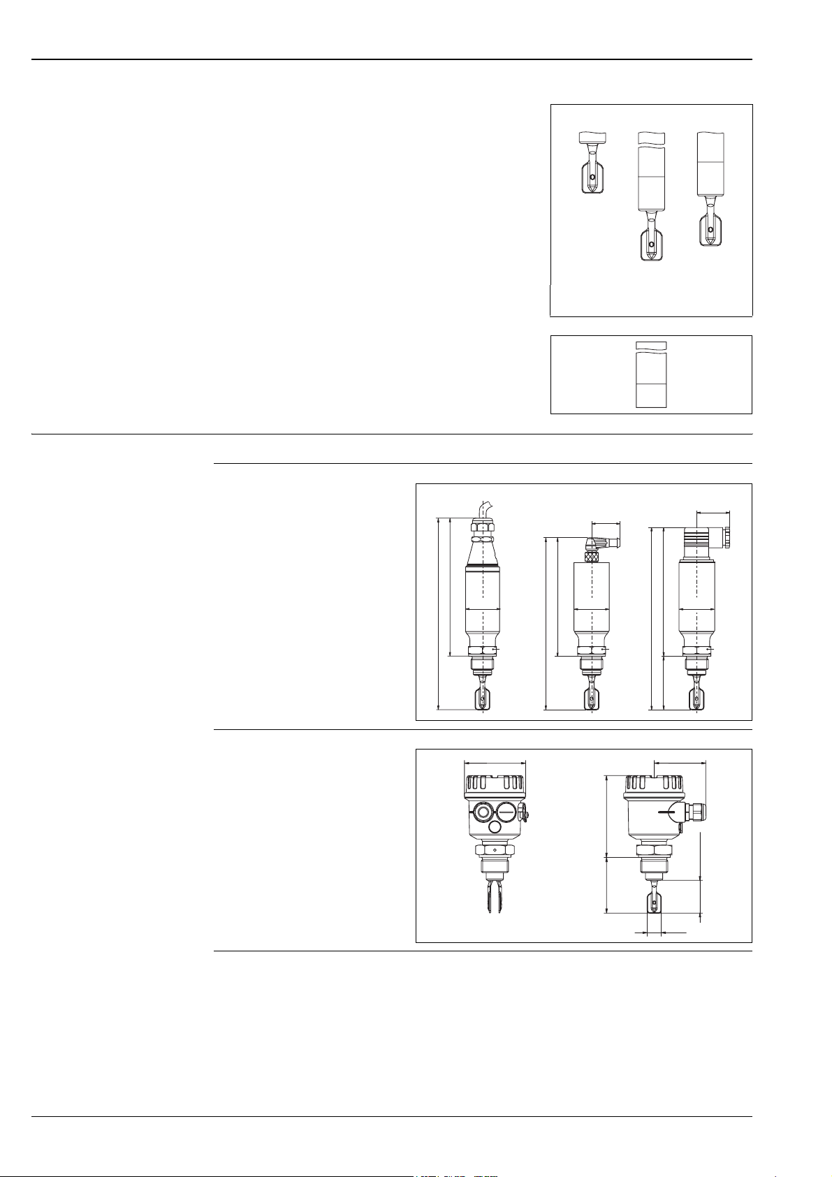
Liquiphant M FTL50(H), FTL51(H)
Dimensions in mm (1 mm = 0,0394 in)
Sensors
Compact,
with extension pipe up to 3 m (to 6 m on request)
or special length "L II" (see also page 30)
Bushings
Temperature spacer and flameproof bushing
Housing and sensor FTL50(H)
Compact housing
Compact Length L Length L II
L00-FTL5xxxx-03-05-xx-xx-018
pe = 64 bar 64 bar 64 bar
100 bar 100 bar
L00-FTL5xxxx-03-05-xx-xx-005
1. 2. 3.
40
30
1. 5 m cable
2. M12 connector
3. Pg11/NPT ½ connector
Polyester housing
232
166
ø40
32 AF
ø85 max. 76
199
133
ø40
max. 155
32 AF
*
141
206
*
L00-FTL5xxxx-06-05-xx-en-008
17.5
L00-FTL5xxxx-06-05-xx-xx-004
ø40
32 AF
max. 40.7
26 Endress+Hauser
Page 27
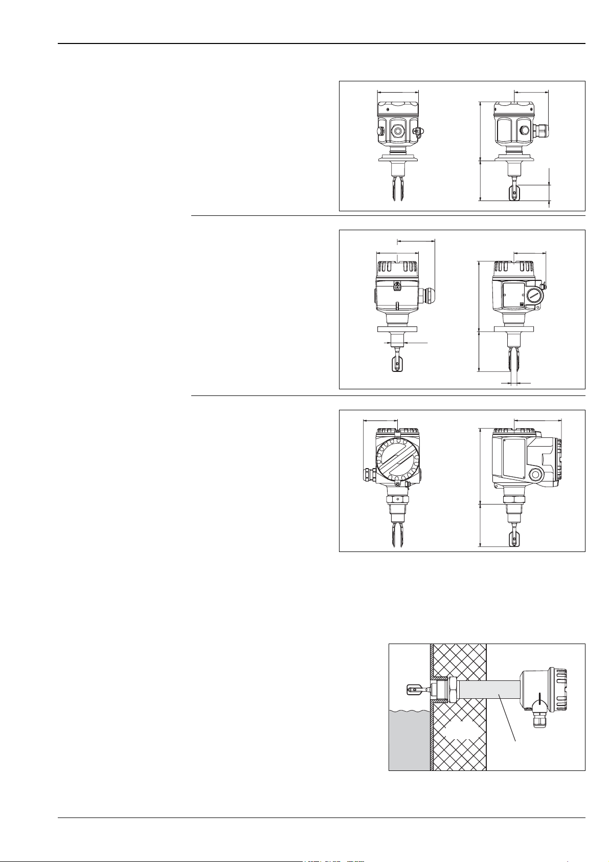
Liquiphant M FTL50(H), FTL51(H)
Steel housing
Aluminium housing
ø76 max. 64
max. 150
*
L00-FTL5xxxx-06-05-xx-xx-005
max. 65
ø80
max. 173
ø21.5
max. 60
*
10
L00-FTL5xxxx-06-05-xx-xx-006
~25
!
Aluminium housing
with separate
max. 65
max. 97
connection compartment
max. 190
*
L00-FTL5xxxx-06-05-xx-xx-007
* see "Process connections"
Note!
The switchpoints of the Liquiphant M are at other positions to those of the previous version Liquiphant II.
Bushings: temperature spacer, flameproof bushing
Temperature spacer
Provides sealed insulation
for the vessel and normal ambient
temperatures for the housing.
Flameproof bushing
Protects the housing from pressures
up to 100 bar if the sensor is damaged.
Provides sealed insulation
for the vessel and normal ambient
temperatures for the housing.
Vessel
insulation
additional length
140 mm
L00-FTL5xxxx-11-05-xx-en-000
Endress+Hauser 27
Page 28
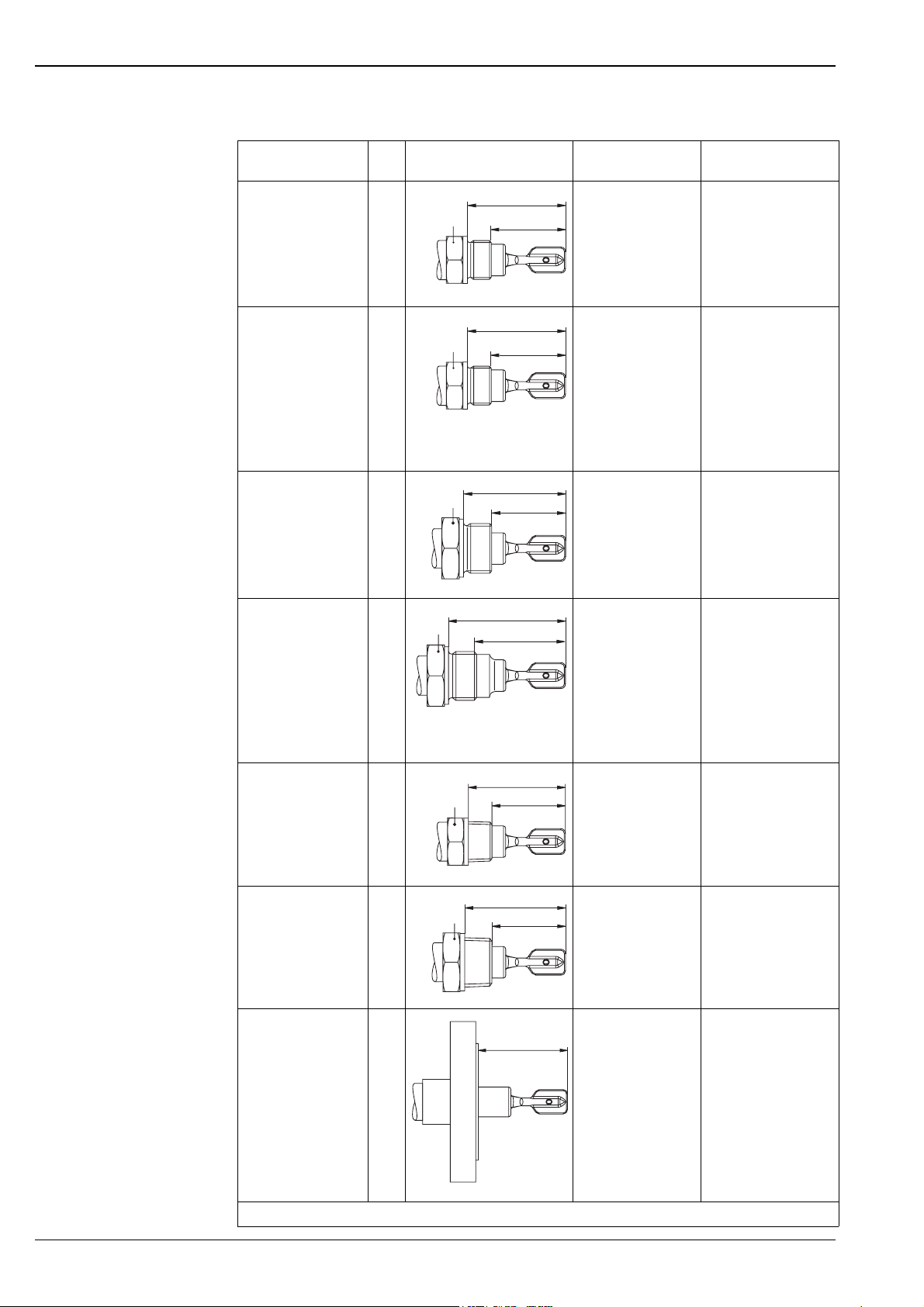
Process connections for FTL50(H) and FTL51(H)
Liquiphant M FTL50(H), FTL51(H)
Process connection Dimensions Accessories Pressure
Temperature
G ¾
DIN ISO 228/l
with defined
GQ2
GQ5
32 AF
66.5
max. 100 bar
max. 150 °C
50.5
thread start
With elastomer
flat seal to DIN 7603:
supplied
G ¾
DIN ISO 228/l
with defined
thread start
For flush-mounted
installation in
welding neck
GQ2
GQ5
32 AF
L00-FTL5xxxx-06-05-xx-en-001
66.5
50.5
L00-FTL5xxxx-06-05-xx-en-001
Welding neck
(with defined
thread start)
with silicone O-ring
Endress+Hauser
52001052
In conformity with
FDA*
max. 25 bar
max. 150 °C
max. 40 bar
max. 100 °C
See "Accessories"
G 1
DIN ISO 228/l
GR2
GR5
41 AF
69
50.5
max. 100 bar
max. 150 °C
With elastomer
flat seal to DIN 7603:
supplied
L00-FTL5xxxx-06-05-xx-en-002
G 1
DIN ISO 228/l
with defined
thread start
With seal surface
for flush-mounted
installation in
welding neck
GW2
41 AF
80
61.3
L00-FTL5xxxx-06-05-xx-en-003
Welding neck
(with defined
thread start)
with silicone O-ring
Endress+Hauser
52001051
In conformity with
FDA*
max. 25 bar
max. 150 °C
max. 40 bar
max. 100 °C
See "Accessories"
NPT ¾
ANSI B 1.20.1
GM2
GM5
32 AF
(66.5)
50.5
In conformity with
FDA*
max. 100 bar
max. 150 °C
or
R ¾
EN10226
NPT 1
ANSI B 1.20.1
GE2
GE5
GN2
GN5
41 AF
L00-FTL5xxxx-06-05-xx-en-004
(69)
50.5
In conformity with
FDA*
max. 100 bar
max. 150 °C
or
R 1
EN10226
Flanges
ANSI B 16.5
EN 1092-1
(DIN 2527 B)
JIS B2220
GF2
GF5
A##
B##
C##
F##
N##
L00-FTL5xxxx-06-05-xx-en-005
66.5
Seal
according to design
installed on site
In conformity with
FDA*
See nominal pressure
of flange, however
max. 100 bar
max. 150 °C
K##
L00-FTL5xxxx-06-05-xx-xx-008
* FDA approved materials according to 21 CFR Part 177.1550/2600
28 Endress+Hauser
Page 29
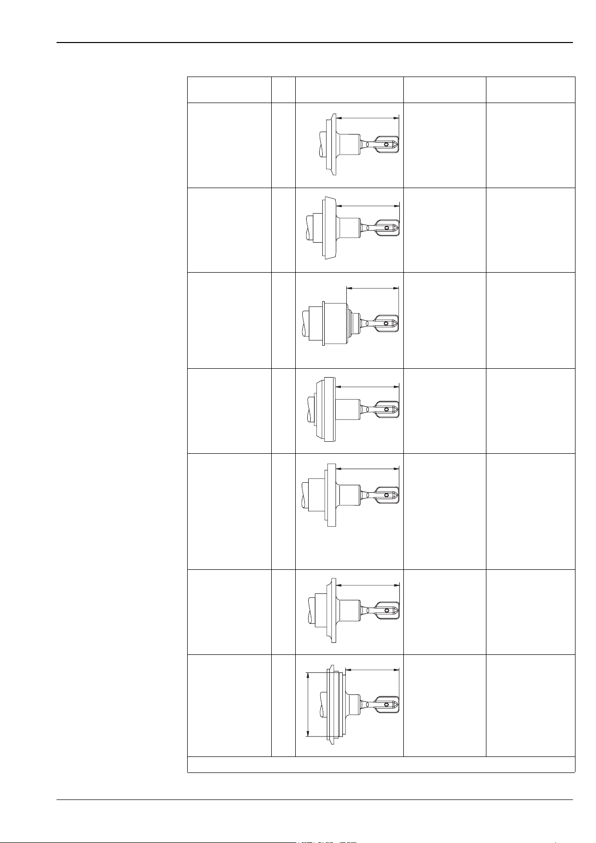
Liquiphant M FTL50(H), FTL51(H)
Process connection Dimensions Accessories Pressure
Temperature
Tri-Clamp
1 ½" = ø50.5 mm
2" = ø64.0 mm
ISO 2852
Threaded pipe joint
DN 32
DN 40
DN 50
DIN 11851
TC2
TE2
MA2
MC2
ME2
66.5
L00-FTL5xxxx-06-05-xx-xx-009
66.5
Clamping ring and
front seal
installed on site
In conformity with
FDA*
Sealing ring with collar,
installed on site
In conformity with
FDA*
max. 16 bar
max. 120 °C
max. 2 bar
max. 150 °C
DN 32, DN 40:
max. 40 bar to 100 °C
max. 25 bar to 140 °C
DN 50:
max. 25 bar
with screw cap
Flush-mounted for 1"
welding neck
Factory standard
Endress+Hauser with
silicone seal
and screw cap:
supplied
EE2
L00-FTL5xxxx-06-05-xx-xx-010
55.5
L00-FTL5xxxx-06-05-xx-xx-011
Welding neck
(fork can be
positioned)
Endress+Hauser
52001047
In conformity with
FDA*
max. 140 °C
max. 40 bar
max. 100 °C
max. 25 bar
max. 150 °C
See "Accessories"
Aseptic
DN 50
DIN 11864-1
Form A
for pipe DIN 11850
HE2
66.5
Sealing ring,
installed on site
In conformity with
FDA*
max. 25 bar
max. 140 °C
with screw cap
DRD
With clamped flange
SMS
2"
(DN 51)
with screw cap
Varivent
for piping
≥ DN 65
≥ O.D. 3"
≥ I.P.S. 3"
PE2
UE2
WE2
ø68
L00-FTL5xxxx-06-05-xx-xx-012
66.5
L00-FTL5xxxx-06-05-xx-xx-013
66.5
L00-FTL5xxxx-06-05-xx-xx-014
56.5
Welding flange with
PTFE flat seal
(fork can be
positioned)
Endress+Hauser
52002041
In conformity with
FDA*
See "Accessories"
(or installed on site)
Sealing ring,
installed on site
In conformity with
FDA*
Clamping ring and
O-ring seal,
installed on site
In conformity with
FDA*
max. 40 bar
max. 100 °C
max. 25 bar
max. 150 °C
max. 25 bar
max. 140 °C
See specification as per
Tuchenhagen VARIVENTInline housing but:
max. 25 bar
max. 150 °C
L00-FTL5xxxx-06-05-xx-xx-015
* FDA approved materials according to 21 CFR Part 177.1550/2600
Endress+Hauser 29
Page 30
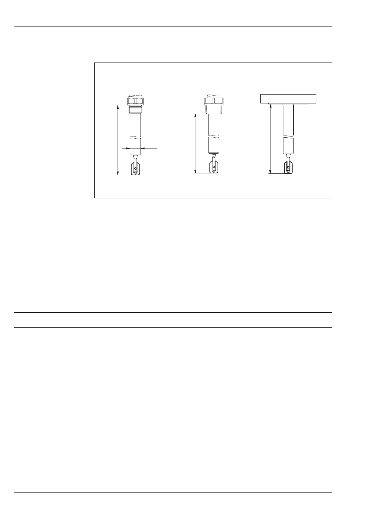
Sensor length L for FTL51 and FTL51H,
depending on process connection
Liquiphant M FTL50(H), FTL51(H)
!
Thread: G ¾
G 1
L
L00-FTL5xxxx-06-05-xx-xx-016
From seal surface of
thread adapter
ø21.5
Thread: NPT ¾
NPT 1
R ¾
R 1
L
L00-FTL5xxxx-06-05-xx-xx-017 L00-FTL5xxxx-06-05-xx-xx-018
From lower edge of
thread
Flanges and
flange-like process connections
L
Any length L:
148...3000 mm (6...115 in); special version (TSP) on request up to 6000 mm (235 in)
Note!
The switchpoints of the Liquiphant M are at other positions to those of the previous version Liquiphant II.
Special length "L II":
With vertical mounting from above the same switchpoint as for the Liquiphant II
FTL360, FTL365, FDL30, FDL35
"L II" depends on process connection:
115 mm for flanges and flange-like process connections
99 mm for threads NPT and R (BSPT)
118 mm for threads G 1 (BSP 1)
115 mm for threads G ¾ (BSP ¾)
104 mm for flush-mounted 1" (Endress+Hauser)
Weights See "Product structure"
Material –Wetted parts:
Process connection and extension pipe: AISI 316L (1.4435) or 2.4610 (AlloyC4)
Tuning fork: AISI 316L (1.4435) or 2.4610 (AlloyC4)
– Flat seal for process connection G ¾ or G 1: elastomer fibre, asbestos-free
– Polyester housing: PBT-FR
with PBT-FR cover or with PA12 cover with sight glass,
Cover seal: EPDM
– Steel housing: AISI 316L,
Cover seal: silicone
– Aluminium housing: EN-AC-AlSi10Mg, plastic-coated,
Cover seal: EPDM
– Compact housing: valve connector or M12 connector
– Cable gland: polyamide or brass, nickel-plated
– Temperature spacer: AISI 316L (1.4435)
– Flameproof bushing: AISI 316L (1.4435)
30 Endress+Hauser
Page 31
Liquiphant M FTL50(H), FTL51(H)
Process connections – Parallel thread G ¾, G 1 to DIN ISO 228/I with flat seal to DIN 7603
– Tapered thread R ¾, R 1 to EN10226
– Tapered thread ¾ -14 NPT, 1 - 11½ NPT to ANSI B 1.20.1
– Flush-mounted with welding neck to factory standard Endress+Hauser (G ¾, G 1)
– Flush-mounted with welding neck to factory standard Endress+Hauser (1"),
Sensor can be positioned
– Tri-Clamp 1½", 2" to ISO 2852
– Threaded pipe joint DN 32, 40, 50 to DIN 11851
– Aseptic connection DN 50 to DIN 11864-1 Form A for pipe DIN 11850
– SMS connection 2" (DN 51)
–DRD flange
– Varivent
®
DN 50 (50/40) to factory standard Tuchenhagen
– Flanges to EN/DIN from DN 25, for standards see "Product structure", to ANSI B 16.5 from 1",
to JIS B2220 (RF)
Human interface
Electronic inserts
With FEL51, FEL52, FEL54, FEL55:
• 2 switches for safety mode and density change,
• green LED to indicate operational status,
• red LED to indicate the switching status,
flashes in the event of corrosion damage
on sensoror if the electronics are defect
With FEL56:
• 2 switches for safety mode and density change,
• green LED flashes to indicate operational status,
• red LED to indicate the switching status,
flashes in the event of corrosion damage
on sensor or if the electronics are defect
With FEL57:
• 2 switches for density change and cyclical checking,
• green LED to indicate operational status,
• yellow LED to indicate the covered status,
flashes in the event of corrosion damage
on sensor or if the electronics are defect
With FEL58:
• 2 switches for safety mode and density change,
• green LED
– flashes quickly to indicate operational status,
– flashes slowly to indicate corrosion damage
at the sensor or if the electronics are defect,
• yellow LED to indicate the switching status,
Test key – breaks the cable connection
L1 N
12
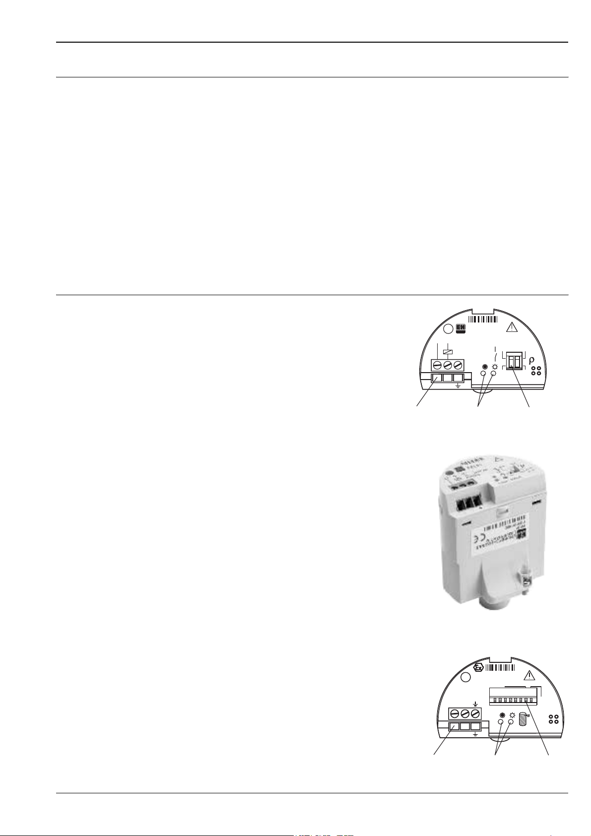
Connecting terminal LEDs Switches
FEL51
U~
19...253V AC
50/60Hz
Max1
2
Min
I max : 350mA
>0,7
>0,5
L00-FTL5xxxx-03-05-xx-en-001
L00-FTL5xxxx-03-05-xx-xx-013
With FEL50A:
• 8 switches for configuring the device address,
• green LED to indicate operational status,
pulsing to indicate communication;
PA– PA+
FEL50A
Address
ON
OFF
12345678
SW
HW
• yellow LED to indicate the switching status,
flashes in the event of corrosion damage on sensor
or if the electronics are defect
Connecting terminal LEDs Switches
12
L00-FTL5xxxx-03-05-xx-en-002
Endress+Hauser 31
Page 32
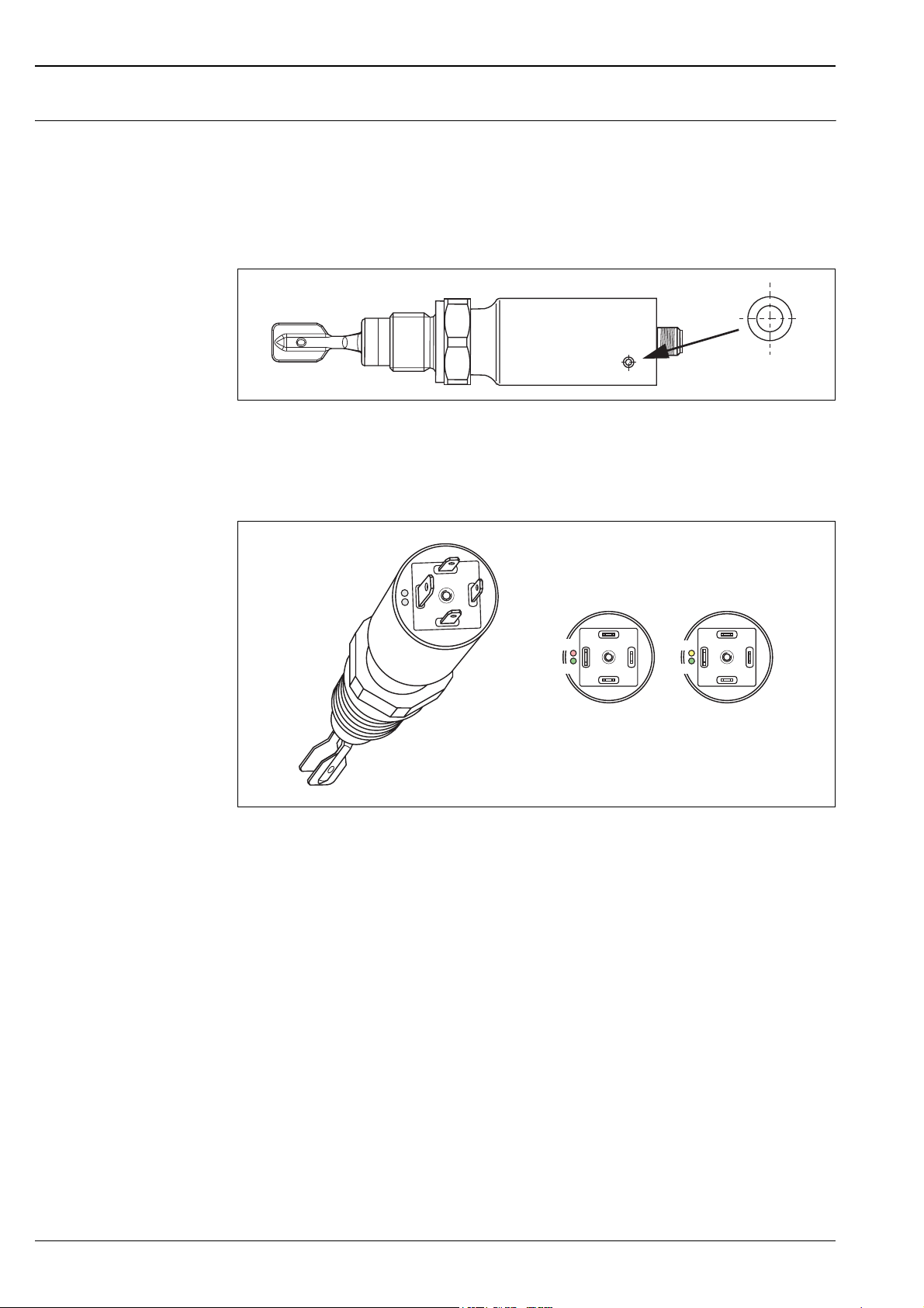
Compact housings Function test with test magnet
Versions AC, DC-PNP and NAMUR:
During the test, the current state of the electronic switch is reversed.
Performing the test
Hold the test magnet against the marking on the nameplate:
Liquiphant M FTL50(H), FTL51(H)
The switching status is changed.
Light signals
Versions AC and DC-PNP with valve connector or cable tail
gn gn
AC/DC NAMUR
rd
L00-FTL5xxxx-19-05-xx-xx-001
ye
L00-FTL5xxxx-07-05-xx-xx-005
Green light (gn) light up (AC/DC):
Liquiphant M is connected to the power supply and is operational.
Green light (gn) flashing (NAMUR):
Liquiphant M is connected to the power supply and is operational.
Red light (rd) lights up (AC/DC):
MAX application mode (overfill protection): sensor is immersed in liquid.
MIN application mode (dry running protection): sensor is not immersed in liquid.
Yellow light (ye) lights up (NAMUR):
MAX application mode (overfill protection): sensor is not immersed in liquid.
MIN application mode (dry running protection): sensor is immersed in liquid.
Red light (rd) flashing (AC/DC):
Liquiphant M has detected a fault.
32 Endress+Hauser
Page 33
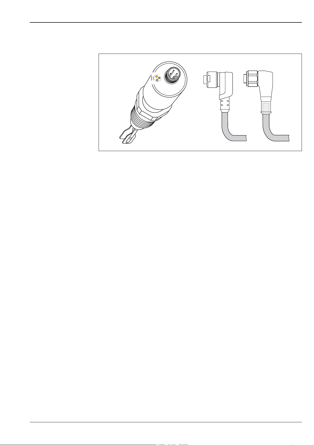
Liquiphant M FTL50(H), FTL51(H)
rd
gn
ye
Version NAMUR and DC-PNP with M12x1 round connector 316L
ye
rd
gn
Green light (gn) lights up (DC-PNP):
Liquiphant M is connected to the power supply and is operational.
L00-FTL5xxxx-07-05-xx-xx-003
Green light (gn) flashing with 1 Hz (NAMUR):
Liquiphant M is connected to the power supply and is operational.
Yellow light (ye) lights up (DC-PNP):
Sensor is immersed in liquid.
Yellow light (ye) lights up (NAMUR):
MAX application mode (overfill protection): sensor is not immersed in liquid.
MIN application mode (dry running protection): sensor is immersed in liquid.
Red light (rd) flashing (DC-PNP):
Liquiphant M has detected a fault.
Green light (gn) flashing with 0.3 Hz (NAMUR):
Liquiphant M has detected a fault.
Endress+Hauser 33
Page 34
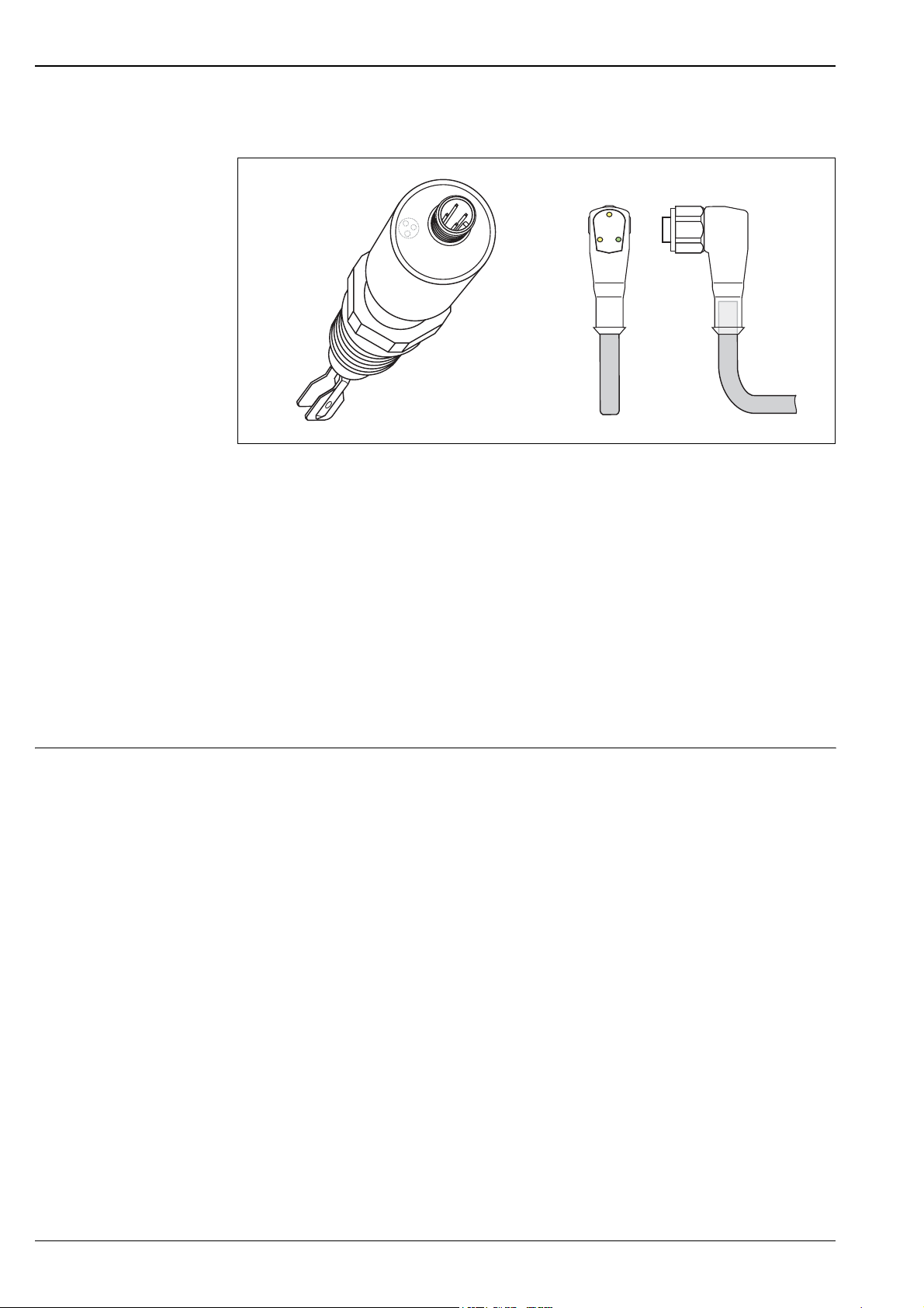
Version DC-PNP with M12x1 round connector 316L
Liquiphant M FTL50(H), FTL51(H)
ye 1
ye 2
gn
Green light (gn) lights up:
Liquiphant M is connected to the power supply and is operational.
Yellow light (ye 1) lights up:
MAX application mode (overfill protection): sensor is not immersed in liquid.
MIN application mode (dry running protection): sensor is not immersed in liquid.
Yellow light (ye 2) lights up:
MAX application mode (overfill protection): sensor is immersed in liquid.
MIN application mode (dry running protection): sensor is immersed in liquid.
L00-FTL5xxxx-07-05-xx-xx-004
Green light (gn) lights up, both yellow lights (ye 1+2) do not light up:
Liquiphant M has detected a fault.
Operating concept Onsite configuration
34 Endress+Hauser
Page 35
Liquiphant M FTL50(H), FTL51(H)
+
Certificates and approvals
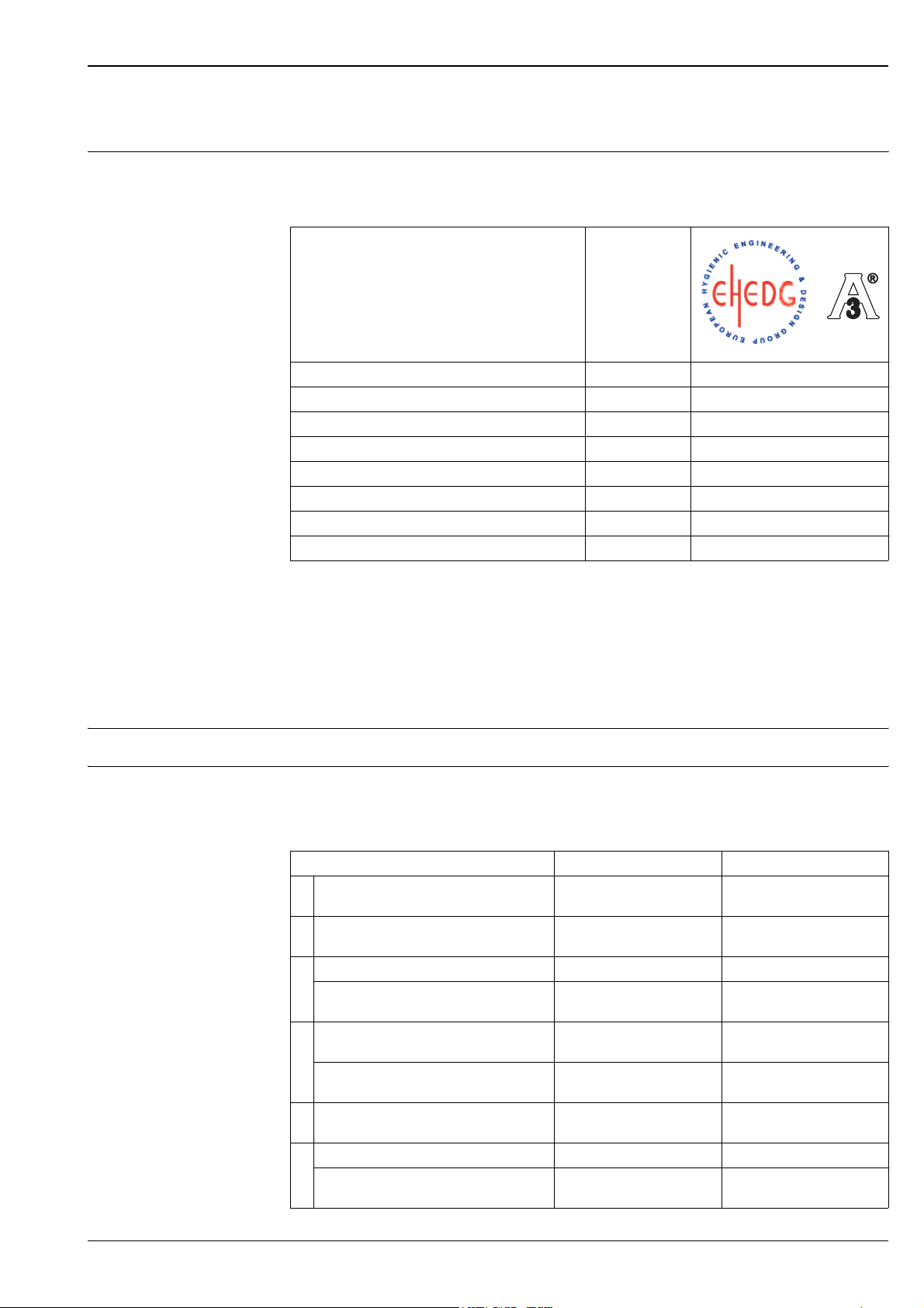
General approvals For Liquiphant M FTL50H, FTL51H the following approvals are available:
• EHEDG: Certification (from TNO, The Netherlands), Report No. V99.394
• 3A: 3A Certificate (USA), Authorization No. 459
!
#
Process connections Order Code
+
L00-FTL5xxxx-01-05-xx-xx-001
Flush-mounted G ¾, G1 (with welding neck) GQ2, GW2 X
Tri-Clamp 2" (special seal from Hyjoin Limited, UK) TE2 X
Threaded pipe joint MA2, MC2, ME2 X
Flush-mounted (fork can be positioned) EE2 X
Aseptic HE2 X
DRD PE2 X
SMS UE2 X
®
Varivent
Note!
For CIP (Clean in Place) and SIP (Sterilize in Place) processes the pressure and temperture specifications of the
process connections must be observed.
Warning!
To avoid risk of contamination, install according to the "Hygienic Equipment Design Criteria (HDC)" as stated
in the Subgroup Design Principles of the EHEDG, Doc. 8, July 1993. The flow of liquid during cleaning is
important and should be in compliance with HDC.
WE2 X
Other certificates See "Ordering information"
Combination of housings and electronic inserts
Based on the various certificates, permissible combinations of housings *) and electronic inserts are given in
the following table.
*) Abbreviations: Polyester = PBT, Steel 316L = St., Aluminium = Alu
Aluminium housing with separate connection compartment = Alu/sep
Certificate, applications Housing Electronic inserts
A Without any special certificate
(for non-hazardous area)
D Overfill protection to WHG (Germany) PBT, St., Alu, Alu/sep. FEL51/52/54,
B ATEX II 3G EEx nC IIC T6, WHG PBT, St., Alu, Alu/sep. FEL54
ATEX II 3G EEx nC IIC T6, WHG
ATEX II 3D T85°C
C ATEX II 3G EEx nA II T6, WHG PBT, St., Alu, Alu/sep. FEL51/52,
ATEX II 3G EEx nA II T6, WHG
ATEX II 3D T85°C
E ATEX II 1/2 G, EEx de, WHG Alu/sep. FEL51/52/54,
F ATEX II 1/2 G, EEx ia IIC T6, WHG PBT, St., Alu, Alu/sep. FEL55/56/57/58/50A
ATEX II 1/2 G, EEx ia IIC T6, WHG
ATEX II 1/2 D, T80°C
PBT, St., Alu, Alu/sep. FEL51/52/54,
FEL55/56/57/58/50A
FEL55/56/57/58/50A
St., Alu, Alu/sep. FEL54
FEL55/56/57/58/50A
St., Alu, Alu/sep. FEL51/52,
FEL55/56/57/58/50A
FEL55/56/57/58/50A
St., Alu, Alu/sep. FEL55/56/57/58/50A
Endress+Hauser 35
Page 36

Liquiphant M FTL50(H), FTL51(H)
Certificate, applications Housing Electronic inserts
G ATEX II 1/2 G, EEx ia IIC T6 PBT, St., Alu, Alu/sep. FEL55/56/57/58/50A
ATEX II 1/2 G, EEx ia IIC T6
ATEX II 1/2 D, T80°C
H ATEX II 1G, EEx ia IIC T6 FEL55/56/57/58/50A
J ATEX II 1G, EEx ia IIC T6, WHG FEL55/56/57/58/50A
I ATEX II 1/2 G, EEx de Alu/sep. FEL51/52/54,
K ATEX II 1/2 G, EEx d IIC T6 Alu FEL51/52/54,
L ATEX II 1/2 G, EEx d IIC T6, WHG Alu FEL51/52/54,
P FM, IS, Cl. I, II, III, Div. 1, Gr. A-G PBT, St., Alu, Alu/sep.
Q FM, XP, Cl. I, II, III, Div. 1, Gr. A-G Alu
R FM, NI, Cl. I, Div. 2, Gr. A-D St., Alu, Alu/sep.
U CSA, General Purpose St., Alu, Alu/sep.
S CSA, IS, Cl. I, II, III, Div. 1, Gr. A-G PBT, St., Alu, Alu/sep.
T CSA, XP, Cl. I, II, III, Div. 1, Gr. A-G Alu
V TIIS Ex ia IIC T3 PBT, St., Alu FEL57
WTIIS Ex d IIB T3 Alu FEL52/54
Y Other certificate
(for non-hazardous area)
St., Alu, Alu/sep. FEL55/56/57/58/50A
FEL55/56/57/58/50A
FEL55/56/57/58/50A
FEL55/56/57/58/50A
FEL55/56/57/58
with NPT cable entry
with NPT cable entry
with NPT cable entry
PBT
with NPT cable entry
with NPT cable entry
PBT
with NPT cable entry
with NPT cable entry
with NPT cable entry
PBT, St., Alu, Alu/sep. FEL51/52/54,
FEL51/52/54,
FEL55/56/57/58
FEL51/52/54,
FEL55/56/57/58
FEL55/56/57/58
FEL51/52/54,
FEL55/56/57/58
FEL51/52,
FEL55/56/57/58
FEL55/56/57/58
FEL51/52/54,
FEL55/56/57/58
FEL55/56/57/58/50A
!
Note!
on polyester housing (PBT), electric connecting cables run in pipes:
Do not screw cable entries firmly to the piping. Use flexible connections (e.g. with armoured hose).
If the piping is used for earthing then ensure that there is a continuous electrical connection.
!
Note!
Despite the additional Dust-Ex-certificate, the FTL5x(H) is to be used as a liquid limit switch only.
36 Endress+Hauser
Page 37

Liquiphant M FTL50(H), FTL51(H)
!
Ordering information
Note!
This overview does not mark options wich are mutually exclusive.
Product structure Liquiphant M FTL50 FTL51
Design Basic weight
FTL50 Compact 0.6 kg
FTL51 With extension pipe 0.6 kg
10 Approval:
A Non-hazardous area
B ATEX II 3 G EEx nC II T6 Overfill protection to WHG (Germany)
ATEX II 3 D T 85 °C*
C ATEX II 3 G EEx nA II T6 Overfill protection to WHG (Germany)
ATEX II 3 D T 85 °C*
D Non-hazardous area Overfill protection to WHG (Germany)
E ATEX II 1/2 G EEx de IIC T6 Overfill protection to WHG (Germany)
F ATEX II 1/2 G EEx ia IIC T6 Overfill protection to WHG (Germany)
ATEX II 1/2 D T 80 °C*
G ATEX II 1/2 G EEx ia IIC T6
ATEX II 1/2 D T 80 °C*
H ATEX II 1 G EEx ia IIC T6
I ATEX II 1/2 G EEx de IIC T6
J ATEX II 1 G EEx ia IIC T6 Overfill protection to WHG (Germany)
K ATEX II 1/2 G EEx d IIC T6
L ATEX II 1/2 G EEx d IIC T6 Overfill protection to WHG (Germany)
P FM IS, Class I, II, III Division 1, Group A-G
Q FM XP, Class I, II, III Division 1, Group B-G, for E5 housing Group A-G
R FM NI, Class I Division 2, Group A-D
S CSA IS, Class I, II, III Division 1, Group A-G
T CSA XP, Class I, II, III Division 1, Group A-G
U CSA General Purpose
VTIIS Ex ia IIC T3
W TIIS Ex d IIB T3
XTIIS Ex ia IIC T6
7 TIIS Ex d IIC T3
8 TIIS Ex d IIC T6
Y Special version
*) not valid for PBT
20 Process Connection: Additional weight
Note!
For 100 bar process pressure, please select the appropriate option under "Additional option"
GQ2 G ¾ 316L Thread ISO 228
Installation > accessory: welding neck
GQ5 G ¾ AlloyC4 Thread ISO 228
GR2 G 1 316L Thread ISO 228 0.2 kg
GR5 G 1 AlloyC4 Thread ISO 228 0.2 kg
GW2 G 1 316L Thread ISO 228 0.2 kg
Installation > accessory: welding neck
GM2 NPT ¾ 316L Thread ANSI
GM5 NPT ¾ AlloyC4 Thread ANSI
GN2 NPT 1 316L Thread ANSI 0.2 kg
GN5 NPT 1 AlloyC4 Thread ANSI 0.2 kg
GE2 R ¾ 316L Thread EN10226
GE5 R ¾ AlloyC4 Thread EN10226
GF2 R 1 316L Thread EN10226 0.2 kg
GF5 R 1 AlloyC4 Thread EN10226 0.2 kg
BA2 DN32 PN6 A 316L Flange EN 1092-1
BB2 DN32 PN25/40 A 316L Flange EN 1092-1
BC2 DN40 PN6 A 316L Flange EN 1092-1
BD2 DN40 PN25/40 A 316L Flange EN 1092-1
BE2 DN50 PN6 A 316L Flange EN 1092-1
(DIN 2527 B)
(DIN 2527 B)
(DIN 2527 B)
(DIN 2527 B)
(DIN 2527 B)
1.2 kg
2.0 kg
1.4 kg
2.4 kg
1.6 kg
Endress+Hauser 37
Page 38

Liquiphant M FTL50(H), FTL51(H)
20 Process Connection: Additional weight
BG2 DN50 PN25/40 A 316L Flange EN 1092-1
BH2 DN65 PN6 A 316L Flange EN 1092-1
BJ2 DN50 PN100 A 316L (FTL51) Flange EN 1092-1
BK2 DN65 PN25/40 A 316L Flange EN 1092-1
BM2 DN80 PN10/16 A 316L Flange EN 1092-1
BN2 DN80 PN25/40 A 316L Flange EN 1092-1
BQ2 DN100 PN10/16 A 316L Flange EN 1092-1
BR2 DN100 PN25/40 A 316L Flange EN 1092-1
B12 DN80 PN100 A 316L (FTL51) Flange EN 1092-1
B82 DN25 PN25/40 A 316L Flange EN 1092-1
CA2 DN32 PN6 B1 316L Flange EN 1092-1
CA5 DN32 PN6 AlloyC4 >316L Flange EN 1092-1
CE2 DN50 PN6 B1 316L Flange EN 1092-1
CE5 DN50 PN6 AlloyC4 >316L Flange EN 1092-1
CG2 DN50 PN25/40 B1 316L Flange EN 1092-1
CG5 DN50 PN25/40 AlloyC4 >316L Flange EN 1092-1
CJ2 DN50 PN100 B2 316L (FTL51) Flange EN 1092-1
CN2 DN80 PN25/40 B1 316L Flange EN 1092-1
CN5 DN80 PN25/40 AlloyC4 >316L Flange EN 1092-1
CQ2 DN100 PN10/16 B1 316L Flange EN 1092-1
CQ5 DN100 PN10/16 AlloyC4 >316L Flange EN 1092-1
C12 DN80 PN100 B2 316L (FTL51) Flange EN 1092-1
C82 DN25 PN25/40 B1 316L Flange EN 1092-1
C85 DN25 PN25/40 AlloyC4 >316L Flange EN 1092-1
DG2 DN50 PN40 B1 316L Flange EN 1092-1
DN2 DN80 PN40 B1 316L Flange EN 1092-1
D82 DN25 PN40 B1 316L Flange EN 1092-1
FG2 DN50 PN40 C 316L Flange EN 1092-1
NG2 DN50 PN40 D 316L Flange EN 1092-1
AA2 1¼" 150 lbs RF 316/316L Flange ANSI B16.5 1.2 kg
AB2 1¼" 300 lbs RF 316/316L (FTL51) Flange ANSI B16.5 2.0 kg
AC2 1½" 150 lbs RF 316/316L Flange ANSI B16.5 1.5 kg
AD2 1½" 300 lbs RF 316/316L (FTL51) Flange ANSI B16.5 2.7 kg
AE2 2" 150 lbs RF 316/316L Flange ANSI B16.5 2.4 kg
AE5 2" 150 lbs RF AlloyC4 >316/316L Flange ANSI B16.5 2.4 kg
AF2 2" 300 lbs RF 316/316L Flange ANSI B16.5 3.2 kg
AG2 2" 600 lbs RF 316/316L (FTL51) Flange ANSI B16.5 4.2 kg
AJ2 2½" 300 lbs RF 316/316L (FTL51) Flange ANSI B16.5 4.8 kg
AL2 3" 150 lbs RF 316/316L Flange ANSI B16.5 4.9 kg
AM2 3" 300 lbs RF 316/316L (FTL51) Flange ANSI B16.5 6.8 kg
AN2 3" 600 lbs RF 316/316L (FTL51) Flange ANSI B16.5
AP2 4" 150 lbs RF 316/316L Flange ANSI B16.5 7.0 kg
AQ2 4" 300 lbs RF 316/316L (FTL51) Flange ANSI B16.5 11.5 kg
AR2 4" 600 lbs RF 316/316L (FTL51) Flange ANSI B16.5 17.3 kg
A82 1" 150 lbs RF 316/316L Flange ANSI B16.5 1.0 kg
(DIN 2527 B)
(DIN 2527 B)
(DIN 2527 B)
(DIN 2527 B)
(DIN 2527 B)
(DIN 2527 B)
(DIN 2527 B)
(DIN 2527 B)
(DIN 2527 B)
(DIN 2527 B)
(DIN 2527 C)
(DIN 2527)
(DIN 2527 C)
(DIN 2527)
(DIN 2527 C)
(DIN 2527)
(DIN 2527)
(DIN 2527 C)
(DIN 2527)
(DIN 2527 C)
(DIN 2527)
(DIN 2527)
(DIN 2527 C)
(DIN 2527)
(DIN 2526 D)
(DIN 2526 D)
(DIN 2526 D)
(DIN 2512 F)
(DIN2512 N)
3.2 kg
2.4 kg
4.3 kg
4.8 kg
5.9 kg
5.6 kg
7.5 kg
1.4 kg
1.1 kg
1.1 kg
1.5 kg
1.5 kg
2.9 kg
2.9 kg
5.2 kg
5.2 kg
5.3 kg
5.3 kg
1.3 kg
1.3 kg
2.6 kg
2.9 kg
38 Endress+Hauser
Page 39
Liquiphant M FTL50(H), FTL51(H)
20 Process Connection: Additional weight
KA2 10 K 25 RF 316L Flange JIS B2220
KC2 10 K 40 RF 316L Flange JIS B2220
KE2 10 K 50 RF 316L Flange JIS B2220 1.7 kg
KE5 10 K 50 RF AlloyC4 >316L Flange JIS B2220 1.7 kg
KL2 10 K 80 RF 316L Flange JIS B2220
KP2 10 K 100 RF 316L Flange JIS B2220
TC2 DN25-38 (1...1½") 316L ISO 2852 Tri-Clamp
TE2 DN40-51 (2") 316L ISO 2852 Tri-Clamp 0.1 kg
YY9 Special version
30 Probe Length; Type:
FTL50
AA Compact; Ra <3.2 μm/80 grit
IA Compact; temperature spacer 0.6 kg
QA Compact; pressure tight feed through 0.7 kg
FTL51
BB ....... mm; 316L** Ra <3.2 μm/80 grit
BE ....... mm; AlloyC4** Ra <3.2 μm/80 grit
CB ....... inch; 316L** Ra <3.2 μm/80 grit
CE ....... inch; AlloyC4** Ra <3.2 μm/80 grit 2.3 kg/100 in
DB Length: type II*; 316L Ra <3.2 μm/80 grit 0.1 kg
DE Length: type II*; AlloyC4 Ra <3.2 μm/80 grit 0.1 kg
JB ....... mm; 316L** + temperature spacer 0.9 kg/m
JE ....... mm; AlloyC4** + temperature spacer 0.9 kg/m
KB ....... inch; 316L** + temperature spacer 2.3 kg/100 in
KE ....... inch; AlloyC4** + temperature spacer 2.3 kg/100 in
LB Length: type II*; 316L + temperature spacer 0.1 kg
LE Length: type II*; AlloyC4 + temperature spacer 0.1 kg
RB ....... mm; 316L** + pressure tight feed through 0.9 kg/m
RE ....... mm; AlloyC4** + pressure tight feed through 0.9 kg/m
SB ....... inch; 316L** + pressure tight feed through 2.3 kg/100 in
SE ....... inch; AlloyC4** + pressure tight feed through 2.3 kg/100 in
TB Length: type II*; 316L + pressure tight feed through 0.1 kg
TE Length: type II*; AlloyC4 + pressure tight feed through 0.1 kg
YY Special version
+0.6 kg
+0.6 kg
+0.6 kg
+0.6 kg
+0.6 kg
+0.6 kg
+0.7 kg
+0.7 kg
+0.7 kg
+0.7 kg
+0.7 kg
+0.7 kg
*) Replacing instruments: when vertically mounting a Liquiphant M
FTL51 with length II, the switch point is at the same height as for the
Liquiphant II FTL360, FTL365, FDL30, FDL35
**) Order 3001...6000 mm (116...235 in) via yy
40 Electronics; Output:
A FEL50A PROFIBUS PA
1 FEL51* 2-wire, 19...253 V AC
2 FEL52* 3-wire PNP, 10... 55 V DC
4 FEL54 relay DPDT, 19...253 V AC, 19...55 V DC
5 FEL55 8/16 mA, 11... 36 V DC
6 FEL56 NAMUR (L-H signal)
7 FEL57 2-wire PFM
8 FEL58* NAMUR + test button (H-L signal)
9 Special version
*) Also available in compact housing
50 Housing; Cable Entry:
C3 Compact 316L IP66/68; cable 5 m
D3 Compact 316L IP65; plug Pg11 ISO 4400
Endress+Hauser 39
Page 40
50 Housing; Cable Entry:
E3 Compact 316L NEMA4X; plug NPT ½ ISO 4400
N3 Compact 316L IP66/68; plug M12
E4 F16 Polyester NEMA4X; thread NPT ½
E5 F13/F17 Alu NEMA4X; thread NPT ¾ 0.5 kg
E6 F15 316L NEMA4X; thread NPT ½ 0.1 kg
E7 T13 Alu coated IP66; thread NPT ¾ 0.9 kg
separate connection compartment
F4 F16 Polyester IP66; thread G ½
F5 F13/F17 Alu IP66; thread G ½ 0.5 kg
F6 F15 316L IP66; thread G ½ 0.1 kg
F7 T13 Alu coated IP66; thread G ½ 0.9 kg
separate connection compartment
G4 F16 Polyester IP66; gland M20
G5 F13/F17 Alu IP66; gland M20 0.5 kg
G6 F15 316L IP66; gland M20 0.1 kg
G7 T13 Alu coated IP66; gland M20 0.9 kg
separate connection compartment (EEx d > thread M20)
N4 F16 Polyester IP66; plug M12
N5 F13/F17 Alu IP66; plug M12
N6 F15 316L IP66; plug M12
Y9 Special version
Liquiphant M FTL50(H), FTL51(H)
(EEx d > thread M20)
!
60 Additional Option:
A Basic version
C EN 10204 - 3.1 material (316L wetted parts)
Inspection certificate
N EN 10204 - 3.1 material, NACE MR0175 (316L wetted parts)
Inspection certificate
P 100 bar process pressure (FTL51)
R 100 bar process pressure, EN 10204 - 3.1 material,
NACE MR0175 (316L wetted parts)
Inspection certificate
S GL/ABS marine certificate (FTL51: max. 1600 mm)
Y Special version
FTL5# - Complete product designation
(FTL51)
Note!
The basic weight includes the compact sensor, thread adapter G ¾, electronic insert, polyester housing
40 Endress+Hauser
Page 41

Liquiphant M FTL50(H), FTL51(H)
Product structure Liquiphant M FTL50H FTL51H
Design Basic weight
FTL50H Compact 0.7 kg
FTL51H With extension pipe 0.7 kg
10 Approval:
A Non-hazardous area
B ATEX II 3 G EEx nC II T6 Overfill protection to WHG (Germany)
ATEX II 3 D T 85 °C*
C ATEX II 3 G EEx nA II T6 Overfill protection to WHG (Germany)
ATEX II 3 D T 85 °C*
D Non-hazardous area Overfill protection to WHG (Germany)
E ATEX II 1/2 G EEx de IIC T6 Overfill protection to WHG (Germany)
F ATEX II 1/2 G EEx ia IIC T6 Overfill protection to WHG (Germany)
ATEX II 1/2 D T 80 °C*
G ATEX II 1/2 G EEx ia IIC T6
ATEX II 1/2 D T 80 °C*
H ATEX II 1 G EEx ia IIC T6
I ATEX II 1/2 G EEx de IIC T6
J ATEX II 1 G EEx ia IIC T6 Overfill protection to WHG (Germany)
K ATEX II 1/2 G EEx d IIC T6
L ATEX II 1/2 G EEx d IIC T6 Overfill protection to WHG (Germany)
P FM IS, Class I, II, III Division 1, Group A-G
Q FM XP, Class I, II, III Division 1, Group B-G, for E5 housing Group A-G
R FM NI, Class I Division 2, Group A-D
S CSA IS, Class I, II, III Division 1, Group A-G
T CSA XP, Class I, II, III Division 1, Group A-G
U CSA General Purpose
VTIIS Ex ia IIC T3
W TIIS Ex d IIB T3
XTIIS Ex ia IIC T6
7 TIIS Ex d IIC T3
8 TIIS Ex d IIC T6
Y Special version
*) not valid for PBT
20 Process Connection: Additional weight
GQ2 G ¾ 316L (FTL50H) Thread ISO 228
Installation > accessory: welding neck
GW2 G 1 316L Thread ISO 228 0.2 kg
Installation > accessory: welding neck
BA2 DN32 PN6 A 316L Flange EN 1092-1
BB2 DN32 PN25/40 A 316L Flange EN 1092-1
BC2 DN40 PN6 A 316L Flange EN 1092-1
BD2 DN40 PN25/40 A 316L Flange EN 1092-1
BE2 DN50 PN6 A 316L Flange EN 1092-1
BG2 DN50 PN25/40 A 316L Flange EN 1092-1
BH2 DN65 PN6 A 316L Flange EN 1092-1
BK2 DN65 PN25/40 A 316L Flange EN 1092-1
BM2 DN80 PN10/16 A 316L Flange EN 1092-1
BN2 DN80 PN25/40 A 316L Flange EN 1092-1
BQ2 DN100 PN10/16 A 316L Flange EN 1092-1
BR2 DN100 PN25/40 A 316L Flange EN 1092-1
B82 DN25 PN25/40 A 316L Flange EN 1092-1
CG2 DN50 PN25/40 B1 316L Flange EN 1092-1
CN2 DN80 PN25/40 B1 316L Flange EN 1092-1
(DIN 2527 B)
(DIN 2527 B)
(DIN 2527 B)
(DIN 2527 B)
(DIN 2527 B)
(DIN 2527 B)
(DIN 2527 B)
(DIN 2527 B)
(DIN 2527 B)
(DIN 2527 B)
(DIN 2527 B)
(DIN 2527 B)
(DIN 2527 B)
(DIN 2527 C)
(DIN 2527 C)
1.2 kg
2.0 kg
1.4 kg
2.4 kg
1.6 kg
3.2 kg
2.4 kg
4.3 kg
4.8 kg
5.9 kg
5.6 kg
7.5 kg
1.4 kg
3.2 kg
5.9 kg
Endress+Hauser 41
Page 42

Liquiphant M FTL50(H), FTL51(H)
20 Process Connection: Additional weight
CQ2 DN100 PN10/16 B1 316L Flange EN 1092-1
EE2 1" flush-mounted (52001047) 316L 0.3 kg
Installation > accessory: welding neck
HE2 DN50 Tube DIN 11850 316L DIN 11864-1 A 0.3 kg
AA2 1¼" 150 lbs RF 316/316L Flange ANSI B16.5 1.2 kg
AC2 1½" 150 lbs RF 316/316L Flange ANSI B16.5 1.5 kg
AE2 2" 150 lbs RF 316/316L Flange ANSI B16.5 2.4 kg
AF2 2" 300 lbs RF 316/316L Flange ANSI B16.5 3.2 kg
AJ2 2½" 300 lbs RF 316/316L (FTL51H) Flange ANSI B16.5 4.8 kg
AL2 3" 150 lbs RF 316/316L Flange ANSI B16.5 4.9 kg
AM2 3" 300 lbs RF 316/316L (FTL51H) Flange ANSI B16.5 6.8 kg
AP2 4" 150 lbs RF 316/316L Flange ANSI B16.5 7.0 kg
AQ2 4" 300 lbs RF 316/316L (FTL51H) Flange ANSI B16.5 11.5 kg
A82 1" 150 lbs RF 316/316L Flange ANSI B16.5 1.0 kg
KA2 10 K 25 RF 316L Flange JIS B2220
KC2 10 K 40 RF 316L Flange JIS B2220
KE2 10 K 50 RF 316L Flange JIS B2220 1.7 kg
KL2 10 K 80 RF 316L Flange JIS B2220
KP2 10 K 100 RF 316L Flange JIS B2220
MA2 DN32 PN25 316L DIN 11851 0.1 kg
MC2 DN40 PN25 316L DIN 11851 0.2 kg
ME2 DN50 PN25 316L DIN 11851 0.3 kg
PE2 DRD 65 mm 316L 0.3 kg
TC2 DN25-38 (1...1½") 316L ISO 2852 Tri-Clamp
TE2 DN40-51 (2") 316L ISO 2852 Tri-Clamp 0.1 kg
UE2 SMS 2" PN25 316L 0.2 kg
WE2 DN65-162 PN10 316L Varivent N tube 0.5 kg
YY9 Special version
(DIN 2527 C)
5.6 kg
30 Probe Length; Type:
FTL50H
AC Compact; Ra <1.5 μm/120 grit
AD Compact; Ra <0.3 μm/320 grit / A3
IC Compact; Ra <1.5 μm/120 grit
ID Compact; Ra <0.3 μm/320 grit / A3
QC Compact; Ra <1.5 μm/120 grit
QD Compact; Ra <0.3 μm/320 grit / A3
FTL51H
BC ....... mm; Ra <1.5 μm/120 grit 0.9 kg/m
BD ....... mm; Ra <0.3 μm/320 grit / A3 0.9 kg/m
CC ....... inch; Ra <1.5 μm/120 grit 2.3 kg/100 in
CD ....... inch; Ra <0.3 μm/320 grit / A3 2.3 kg/100 in
DC Length: type II*; Ra <1.5 μm/120 grit 0.1 kg
DD Length: type II*; Ra <0.3 μm/320 grit / A3 0.1 kg
JC ....... mm; Ra <1.5 μm/120 grit
JD ....... mm; Ra <0.3 μm/320 grit
KC ....... inch; Ra <1.5 μm/120 grit
KD ....... inch; Ra <0.3 μm/320 grit
LC Length: type II*; Ra <1.5 μm/120 grit
LD Length: type II*; Ra <0.3 μm/320 grit
RC ....... mm; Ra <1.5 μm/120 grit
RD ....... mm; Ra <0.3 μm/320 grit
SC ....... inch; Ra <1.5 μm/120 grit
SD ....... inch; Ra <0.3
+ temperature spacer
+ temperature spacer
+ pressure tight feed through
+ pressure tight feed through
+ temperature spacer
+ temperature spacer
+ temperature spacer
+ temperature spacer
+ temperature spacer
+ temperature spacer
+ pressure tight feed through
+ pressure tight feed through
+ pressure tight feed through
μm/320 grit
+ pressure tight feed through
0.6 kg
0.6 kg
0.7 kg
0.7 kg
0.9 kg/m
+0.6 kg
0.9 kg/m
+0.6 kg
2.3 kg/100 in
+0.6 kg
2.3 kg/100 in
+0.6 kg
0.1 kg
+0.6 kg
0.1 kg
+0.6 kg
0.9 kg/m
+0.7 kg
0.9 kg/m
+0.7 kg
2.3 kg/100 in
+0.7 kg
2.3 kg/100 in
+0.7 kg
42 Endress+Hauser
Page 43
Liquiphant M FTL50(H), FTL51(H)
30 Probe Length; Type:
TC Length: type II*; Ra <1.5 μm/120 grit
TD Length: type II*; Ra <0.3 μm/320 grit
YY Special version
*) Replacing instruments: when vertically mounting a Liquiphant M
FTL51H with length II, the switch point is at the same height as for the
Liquiphant II FTL360, FTL365, FDL30, FDL35
40 Electronics; Output:
A FEL50A PROFIBUS PA
1 FEL51* 2-wire, 19...253 V AC
2 FEL52* 3-wire PNP, 10... 55 V DC
4 FEL54 relay DPDT, 19...253 V AC, 19...55 V DC
5 FEL55 8/16 mA, 11... 36 V DC
6 FEL56 NAMUR (L-H signal)
7 FEL57 2-wire PFM
8 FEL58* NAMUR + test button (H-L signal)
9 Special version
*) Also available in compact housing
+ pressure tight feed through
+ pressure tight feed through
0.1 kg
+0.7 kg
0.1 kg
+0.7 kg
50 Housing; Cable Entry:
C3 Compact 316L IP66/68; cable 5 m
D3 Compact 316L IP65; plug Pg11 ISO 4400
E3 Compact 316L NEMA4X; plug NPT ½ ISO 4400
N3 Compact 316L IP66/68; plug M12
E4 F16 Polyester NEMA4X; thread NPT ½ –0.1 kg
E5 F13/F17 Alu NEMA4X; thread NPT ¾ 0.4 kg
E6 F15 316L NEMA4X; thread NPT ½
E7 T13 Alu coated IP66; thread NPT ¾ 0.8 kg
separate connection compartment
F4 F16 Polyester IP66; thread G ½ –0.1 kg
F5 F13/F17 Alu IP66; thread G ½ 0.4 kg
F6 F15 316L IP66; thread G ½
F7 T13 Alu coated IP66; thread G ½ 0.8 kg
separate connection compartment
G4 F16 Polyester IP66; gland M20 –0.1 kg
G5 F13/F17 Alu IP66; gland M20 0.4 kg
G6 F15 316L IP66; gland M20
G7 T13 Alu coated IP66; gland M20 0.8 kg
separate connection compartment (EEx d > thread M20)
N4 F16 Polyester IP66; plug M12
N5 F13/F17 Alu IP66; plug M12
N6 F15 316L IP66; plug M12
Y9 Special version
60 Additional Option:
A Basic version
B CoC, EN 10204 - 3.1 material (316L wetted parts)
Inspection certificate
C EN 10204 - 3.1 material (316L wetted parts)
Inspection certificate
S GL/ABS marine certificate (FTL51H: max. 1600 mm)
Y Special version
(EEx d > thread M20)
FTL5#H - Complete product designation
!
Note!
The basic weight includes the compact sensor, thread adapter G ¾, electronic insert, steel housing
Endress+Hauser 43
Page 44
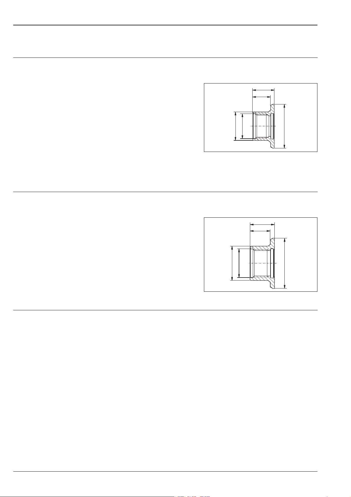
Accessories
Liquiphant M FTL50(H), FTL51(H)
Welding neck G ¾
Welding neck G 1
Order number: 52001052
with 3.1.B material certificate: 52011897
for flush-mounting
a Liquiphant FTL50 or FTL50H
with process connection GQ2
• With defined thread start *
• Sensor cannot be positioned
Material: corrosion-resistant steel
1.4435 (AISI 316L)
Weight: 0.13 kg
Seal: silicone O-ring
Order number: 52001387
FDA approved materials according to
21 CFR Part 177.1550/2600
Note!
!
Use only for FTL50/51 and FTL50H/51H!
Order number: 52001051
with 3.1.B material certificate: 52011896
for flush-mounting
a Liquiphant M
with process connection GW2
• With defined thread start *
• Sensor cannot be positioned
Material: corrosion-resistant steel
1.4435 (AISI 316L)
Weight: 0.19 kg
Seal: silicone O-ring
Order number: 52001386
FDA approved materials according to
21 CFR Part 177.1550/2600
ø41
ø32
max. 25 bar / max. 150 °C
max. 40 bar / max. 100 °C
26
21
G¾
ISO 228
max. 25 bar / max. 150 °C
max. 40 bar / max. 100 °C
29.6
24.6
G1
ISO 228
–0.4
ø55
L00-FTL5xxxx-06-05-xx-xx-019
–0.4
ø60
L00-FTL5xxxx-06-05-xx-xx-020
* The tolerance of the defined thread beginnings between welding boss and sensor amounts to ± 15°.
44 Endress+Hauser
Page 45
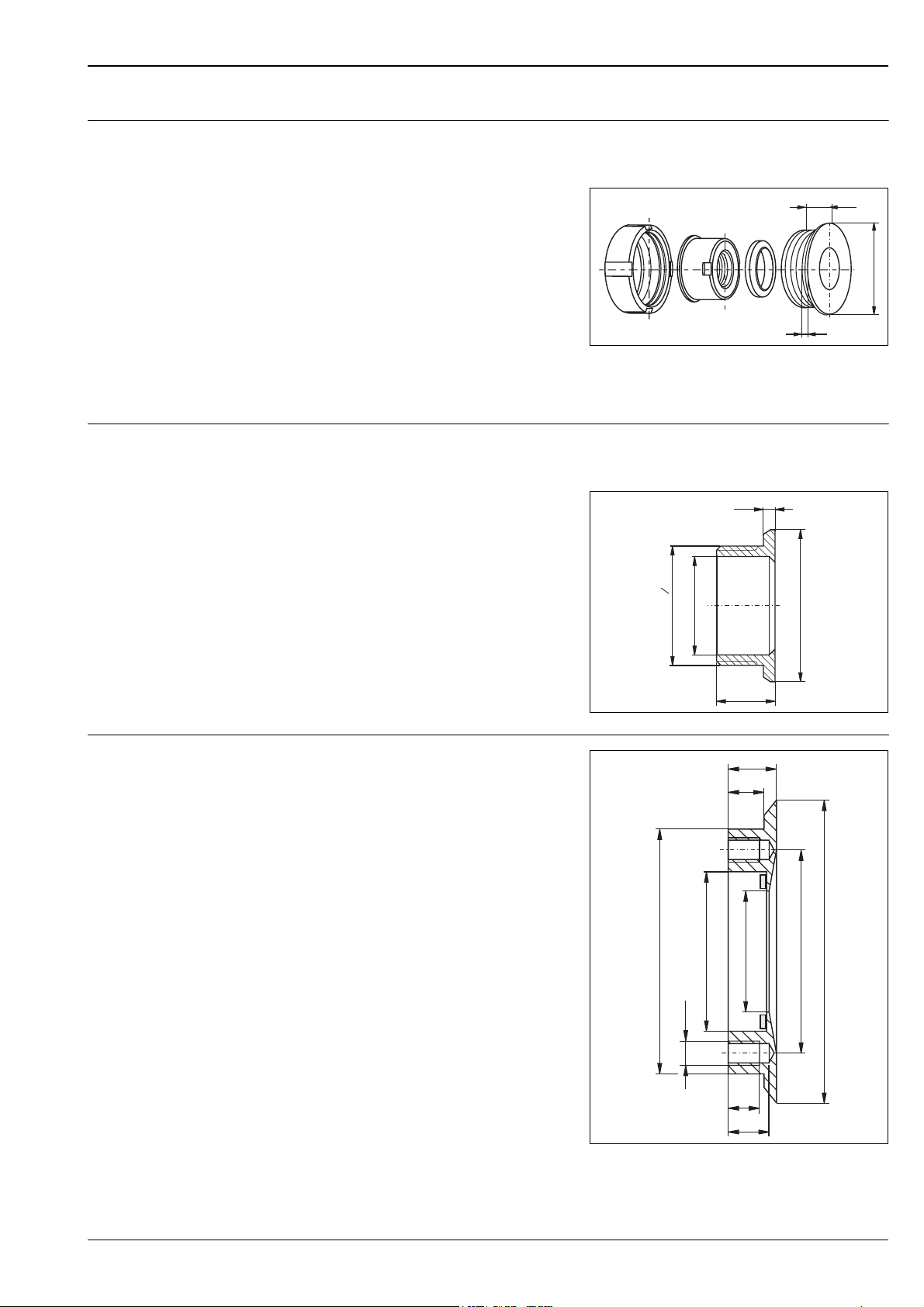
Liquiphant M FTL50(H), FTL51(H)
Welding neck G 1
Welding neck
Order number: 52001221
with 3.1.B material certificate: 52011898
for flush-mounting
a Liquiphant M
with process connection GW2
• Sensor can be positioned
Material (wetted):
corrosion-resistant steel
1.4435 (AISI 316L)
Weight: 0.43 kg
Seal: silicone moulded seal
Order number: 942816-0000
FDA approved materials according to
21 CFR Part 177.1550/2600
Order number: 52001047
with 3.1.B material certificate: 52006909
for flush-mounting
a Liquiphant FTL50H, FTL51H
with process connection EE2
• Sensor can be positioned
Material: corrosion-resistant steel
1.4435 (AISI 316L)
Weight: 0.15 kg
Seal on Liquiphant: silicone moulded seal
Order number: 942816-0000
FDA approved materials according to
21 CFR Part 177.1550/2600
max. 25 bar / max. 150 °C
max. 40 bar / max. 100 °C
26
–0.3
ø65
5
L00-FTL5xxxx-06-05-xx-xx-021
max. 25 bar / max. 150 °C
max. 40 bar / max. 100 °C
4.5
6
1
ø42.3
RD 52 x
~26
ø65
L00-FTL5xxxx-06-05-xx-xx-022
DRD welding flange
Order number: 52002041
with 3.1.B material certificate: 52011899
for flush-mounting
a Liquiphant FTL50H, FTL51H
with process connection PE2
• Sensor can be positioned
Material: corrosion-resistant steel
1.4435 (AISI 316L)
Weight: 0.9 kg
Seal: PTFE flat seal (FDA listed)
Order number: 916783-0000
FDA approved materials according to
21 CFR Part 177.1550/2600
ø105
M10
ø66
20
15
ø50
13
16
ø84
ø125
L00-FTL5xxxx-06-05-xx-xx-023
Endress+Hauser 45
Page 46
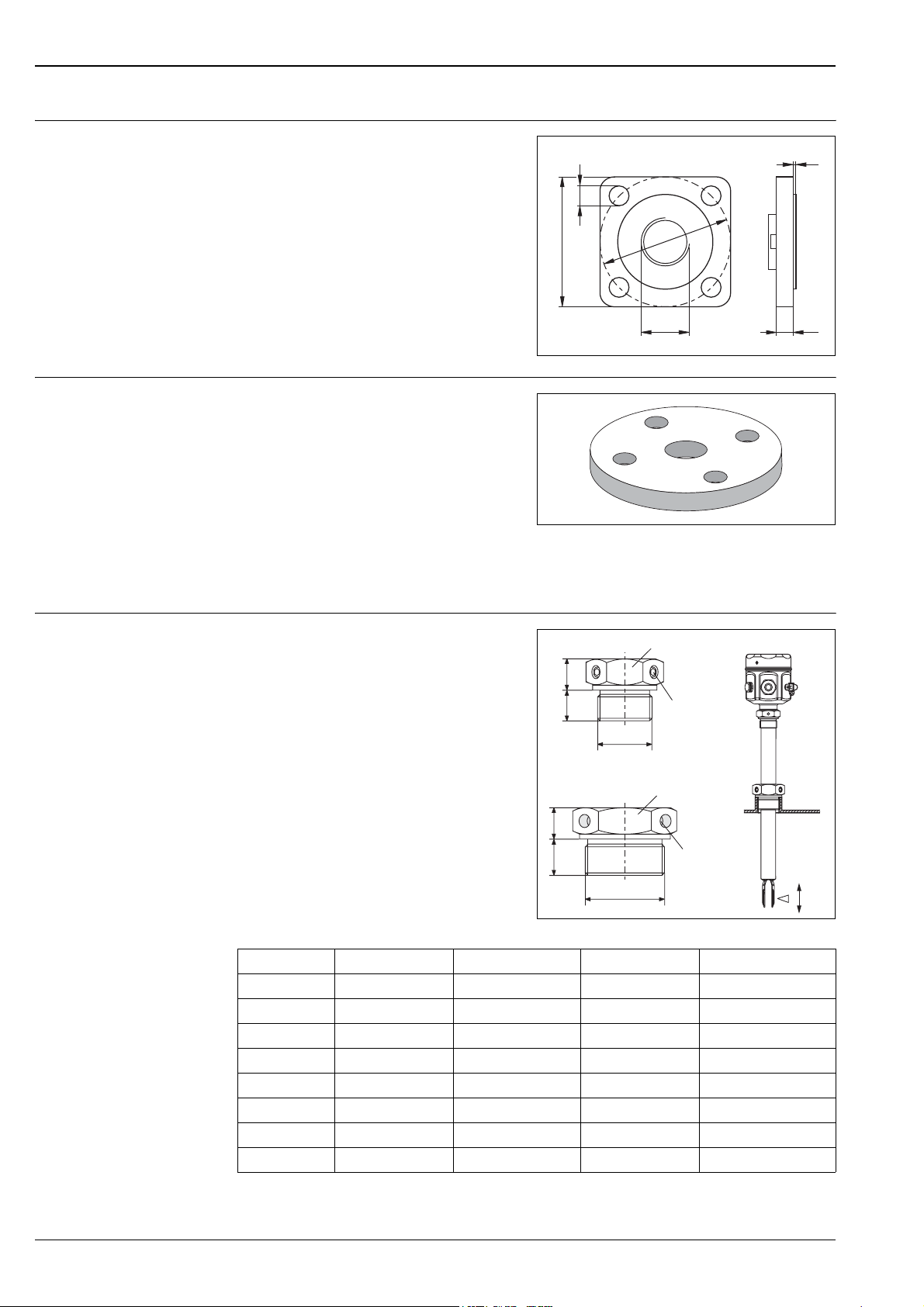
Liquiphant M FTL50(H), FTL51(H)
Lap joint flange
Lap joint flanges
Order number: 918158-0000
with G 1 thread for mounting
a Liquiphant FTL50, FTL51
with process connection GR2
Pressure up to 40 bar
Material: corrosion-resistant steel
1.4301 (AISI 304)
Weight: 0.54 kg
with G 1 thread for mounting
a Liquiphant FTL50, FTL51
with process connection GR2
Material: corrosion-resistant steel
1.4571 (AISI 316Ti)
– Order number: 918143-0000
Flange DN50 PN40, EN 1092-1
Weight: 3.11 kg
– Order number: 918144-0000
Flange ANSI 2", 150 psi, RF
Weight: 2.38 kg
2
14
92
92
G1 12
L00-FTL5xxxx-06-05-xx-xx-024
L00-FTL5xxxx-03-05-xx-xx-015
Sliding sleeves for unpressurised operation
for continuous adjustment of the switch point
of a Liquiphant M FTL51
Material: corrosion-resistant steel
41 AF
19
FTL51
1.4435 (AISI 316L)
Weight for G 1, NPT 1: 0.21 kg
Weight for G 1½, NPT 1½: 0.54 kg
18
G1A
(1 NPT)
19
22
G1½A
(1½ NPT)
Thread Standard Material Order number Approval
G 1 DIN ISO 228/I 1.4435 (AISI 316L) 52003978
G 1 DIN ISO 228/I 1.4435 (AISI 316L) 52011888 3.1 material certificate
NPT 1 ANSI B 1.20.1 1.4435 (AISI 316L) 52003979
NPT 1 ANSI B 1.20.1 1.4435 (AISI 316L) 52011889 3.1 material certificate
G 1½ DIN ISO 228/I 1.4435 (AISI 316L) 52003980
G 1½ DIN ISO 228/I 1.4435 (AISI 316L) 52011890 3.1 material certificate
NPT 1½ ANSI B 1.20.1 1.4435 (AISI 316L) 52003981
NPT 1½ ANSI B 1.20.1 1.4435 (AISI 316L) 52011891 3.1 material certificate
M6 (3x)
55 AF
M6 (3x)
p=
e
0 bar
L00-FTL5xxxx-06-05-xx-en-006
46 Endress+Hauser
Page 47
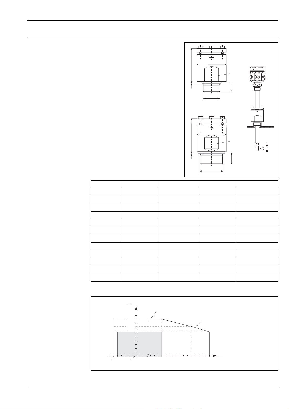
Liquiphant M FTL50(H), FTL51(H)
G 1AA
(1 NPT)
G 1½AA
(1½ NPT)
FTL51
18
ø60
2
~70
22
ø60
2
~72
AF
AF
High pressure sliding sleeves
For continuous adjustment of the switch point
of a Liquiphant M FTL51.
Material: corrosion-resistant steel
1.4435 (AISI 316L) or AlloyC4
Weight for G 1, NPT 1: 1.13 kg
Weight for G 1½, NPT 1½: 1.32 kg
Seal package made of graphite
~70
2
~72
2
ø60
G1
(1 NPT)
ø60
G1½
(1½ NPT)
5050AF
18
5050AF
22
Thread Standard Material Order number Approval
G 1 DIN ISO 228/1 1.4435 (AISI 316L) 52003663
G 1 DIN ISO 228/1 1.4435 (AISI 316L) 52011880 3.1 material certificate
G 1 DIN ISO 228/1 AlloyC4 52003664
NPT 1 ANSI B 1.20.1 1.4435 (AISI 316L) 52003667
NPT 1 ANSI B 1.20.1 1.4435 (AISI 316L) 52011881 3.1 material certificate
NPT 1 ANSI B 1.20.1 AlloyC4 52003668
G 1½ DIN ISO 228/1 1.4435 (AISI 316L) 52003665
G 1½ DIN ISO 228/1 1.4435 (AISI 316L) 52011882 3.1 material certificate
G 1½ DIN ISO 228/1 AlloyC4 52003666
NPT 1½ ANSI B 1.20.1 1.4435 (AISI 316L) 52003669
NPT 1½ ANSI B 1.20.1 1.4435 (AISI 316L) 52011883 3.1 material certificate
NPT 1½ ANSI B 1.20.1 AlloyC4 52003670
FTL51
L00-FTL5xxxx-06-05-xx-en-007
p
e
bar
(psi)
100
(1450)
(1160)
(928)
Liquiphant M FTL51*
Liquiphant S
80
64
Liquiphant M
T
p
–60
(–76)
–50
(–58)
–1
(–14.5)
(32)
0
150
(300)
230
(440)
280
(540)
°C
(°F)
L00-FTL5xxxx-05-05-xx-xx-002
* FTL51 with high pressure sliding sleeves (1450 psi). See "Additional Option" Page 37 ff. option "P" or "R".
Endress+Hauser 47
Page 48
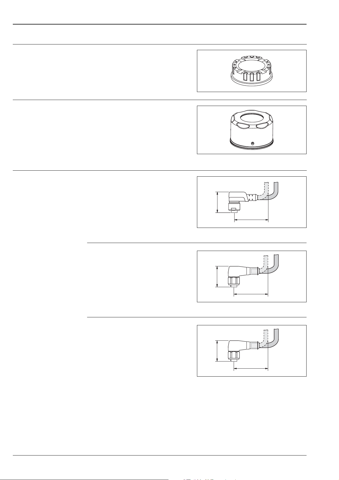
Liquiphant M FTL50(H), FTL51(H)
Transparent cover
Cover with sight glass
Circular connector
Order number: 943461-0001
for polyester housing
Material: PA 12
Weight: 0.04 kg
for steel housing
Material: AISI 316L
Weight: 0.16 kg
– Order number: 943301-1000
With glass sight glass
– Order number: 52001403
With PC sight glass
(Not for CSA, General Purpose)
Order number: 52010285
4x0,34 M12 socket
Cable: PVC (grey) 5 m length
Body: PUR (blue)
Coupling nut: Cu Sn/Ni
Protection: IP67
Temperature range: –25...+70 °C
L00-FTL5xxxx-03-05-xx-xx-016
L00-FTL5xxxx-03-05-xx-xx-017
27.5
min. 40
L00-FTL20Hxx-07-05-xx-xx-004
Order number: 52024216
4x0,34 M12 socket
Cable: PVC (orange) 5 m length
Body: PVC (orange)
Coupling nut: 316L
Protection: IP69K (fully locked)
Temperature range: –25...+70 °C
Order number: 52018763
4x0,34 M12 socket with integrated LEDs
Cable: PVC (orange) 5 m length
Body: PVC (transparent)
Coupling nut: 316L
Protection: IP69K (fully locked)
Temperature range: –25...+70 °C
27.5
min. 40
L00-FTL20Hxx-07-05-xx-xx-005
27.5
min. 40
L00-FTL20Hxx-07-05-xx-xx-005
48 Endress+Hauser
Page 49

Liquiphant M FTL50(H), FTL51(H)
Supplementary Documentation
!
Operating Instructions Electronic insert FEL50A for Liquiphant M/S
Note!
This supplementary documentation can be found on our product pages on www.endress.com
PROFIBUS PA
BA141F/00/en
Liquiphant M FTL50, FTL51
KA143F/00/a6
Liquiphant M FTL50(H), FTL51(H)
KA144F/00/a6
Liquiphant M FTL51C
KA162F/00/a6
Liquiphant M FTL50-####### # 7 #, FTL51-####### # 7 #
KA163F/00/a6
Liquiphant M FTL50H-######## 7 #, FTL51H-######## 7 #
KA164F/00/a6
Liquiphant M FTL51C-######## 7 ##
KA165F/00/a6
Liquiphant M FTL5#-# ### ## # #3 #, FTL5#H-# ### ## # #3 #
KA220F/00/a6
Technical Information Nivotester FTL370/372, switching units in Racksyst design
for Liquiphant M with electronic insert FEL57
TI198F/00/en
Nivotester FTL320, switching unit in Minipac design
for Liquiphant M with electronic insert FEL57
TI203F/00/en
General instructions for electromagnetic compatibility
(Test procedure, installation recommendation)
TI241F/00/en
Isolating amplifier FXN421/422, switching units for top-hat rail mounting
for Liquiphant M with electronic insert FEL56, FEL58
TI332F/00/en
Liquiphant M FTL51C, wetted parts with highly corrosion-resistant coating
made of ECTFE, PFA or enamel
TI347F/00/en
Isolating amplifier FTL325P, 1 or 3-channel switching units for top-hat rail mounting
for Liquiphant M/S with electronic insert FEL57
TI350F/00/en
Isolating amplifier FTL325N, 1 or 3-channel switching units for top-hat rail mounting
for Liquiphant M/S with electronic insert FEL56, FEL58
TI353F/00/en
Liquiphant S FTL70/71, for medium temperatures up to 280 °C
TI354F/00/en
Isolating amplifier FTL375P, 1 to 3-channel switching units for top-hat rail mounting
for Liquiphant M/S with electronic insert FEL57
TI360F/00/en
Isolating amplifier FTL375N, 1 to 3-channel switching units for top-hat rail mounting
for Liquiphant M/S with electronic insert FEL56, FEL58
TI361F/00/en
Endress+Hauser 49
Page 50

Functional Safety (SIL) Liquiphant M/S + Nivotester FTL325P
SD111F/00/en
Liquiphant M/S + Nivotester FTL375P
SD113F/00/en
Liquiphant M/S with FEL58 + Nivotester FTL325N (MAX)
SD161F/00/en
Liquiphant M/S with electronic insert FEL54 (MAX)
SD162F/00/en
Liquiphant M/S with electronic insert FEL52 (MAX)
SD163F/00/en
Liquiphant M/S with electronic insert FEL51 (MAX)
SD164F/00/en
Liquiphant M/S with electronic insert FEL55 (MAX)
SD167F/00/en
Liquiphant M/S with FEL56 + Nivotester FTL325N (MAX)
SD168F/00/en
Liquiphant M/S with FEL58 + Nivotester FTL325N (MIN)
SD170F/00/en
Liquiphant M/S with electronic insert FEL51 (MIN)
SD185F/00/en
Liquiphant M/S with electronic insert FEL52 (MIN)
SD186F/00/en
Liquiphant M/S with electronic insert FEL54 (MIN)
SD187F/00/en
Liquiphant M/S with FEL56 + Nivotester FTL325N (MIN)
SD188F/00/en
Liquiphant M FTL50(H), FTL51(H)
Safety Instructions (ATEX) 40II 1/2 G, EEx d IIC/B
(KEMA 99 ATEX 1157)
XA031F/00/a3
40II 1/2 G, EEx ia/ib IIC/B
(KEMA 99 ATEX 0523)
XA063F/00/a3
40II 1 G, EEx ia IIC/B
(KEMA 99 ATEX 5172 X)
XA064F/00/a3
40II 1/2 G, EEx de IIC/B
(KEMA 00 ATEX 2035)
XA108F/00/a3
40II 3 G, EEx nA/nC II
(EG 01 007-a)
XA182F/00/a3
System Information Liquiphant M
SI040F/00/en
50 Endress+Hauser
Page 51

Liquiphant M FTL50(H), FTL51(H)
Endress+Hauser 51
Page 52

Instruments International
Endress+Hauser
Instruments International AG
Kaegenstrasse 2
4153 Reinach
Switzerland
Tel. +41 61 715 81 00
Fax +41 61 715 25 00
www.endress.com
[email protected]
TI328F/00/en/07.07
SL/FM+SGML6.0 ProMoDo
 Loading...