

Endress+Hauser Cubemass DCI Technical Information
Technical Information
Cubemass DCI
Coriolis mass flow measuring system
Applications
The Coriolis measuring principle operates independently
of physical fluid properties.
• Fluid temperatures up to +200 °C (+392 °F)
• Process pressures up to 400 bar (5800 psi)
• Mass flow measurement up to 1000 kg/h
(36.75 lb/min)
Approvals for hazardous area:
• ATEX, NEC/CEC, NEPSI
Connection to commonly used process control systems:
• MODBUS RS485
Your benefits
The Cubemass DCI make it possible to simultaneously
record several process variables (mass/density/
temperature) for various process conditions during
measuring operation.
The transmitter concept includes:
• FieldCare for onsite operation and diagnosis
• Very low power consumption
TI099D/06/en/04.10
71112154

Table of contents
Cubemass DCI
Function and system design. . . . . . . . . . . . . . . . . . . . . 3
Measuring principle . . . . . . . . . . . . . . . . . . . . . . . . . . . . . . . . . . . 3
Measuring system . . . . . . . . . . . . . . . . . . . . . . . . . . . . . . . . . . . . . 4
Input . . . . . . . . . . . . . . . . . . . . . . . . . . . . . . . . . . . . . . 5
Measured variable . . . . . . . . . . . . . . . . . . . . . . . . . . . . . . . . . . . . 5
Measuring range . . . . . . . . . . . . . . . . . . . . . . . . . . . . . . . . . . . . . . 5
Operable flow range . . . . . . . . . . . . . . . . . . . . . . . . . . . . . . . . . . . 5
Input signal . . . . . . . . . . . . . . . . . . . . . . . . . . . . . . . . . . . . . . . . . 5
Output . . . . . . . . . . . . . . . . . . . . . . . . . . . . . . . . . . . . . 6
Output signal . . . . . . . . . . . . . . . . . . . . . . . . . . . . . . . . . . . . . . . . 6
Signal on alarm . . . . . . . . . . . . . . . . . . . . . . . . . . . . . . . . . . . . . . 6
Switching output . . . . . . . . . . . . . . . . . . . . . . . . . . . . . . . . . . . . . 6
Load . . . . . . . . . . . . . . . . . . . . . . . . . . . . . . . . . . . . . . . . . . . . . . 6
Galvanic isolation . . . . . . . . . . . . . . . . . . . . . . . . . . . . . . . . . . . . . 6
Power supply . . . . . . . . . . . . . . . . . . . . . . . . . . . . . . . . 7
Electrical connection Measuring unit . . . . . . . . . . . . . . . . . . . . . . 7
Electrical connection, terminal assignment . . . . . . . . . . . . . . . . . . 8
Electrical connection, Remote version . . . . . . . . . . . . . . . . . . . . . . 8
Supply voltage . . . . . . . . . . . . . . . . . . . . . . . . . . . . . . . . . . . . . . . 8
Cable entries . . . . . . . . . . . . . . . . . . . . . . . . . . . . . . . . . . . . . . . . 8
Cable specifications . . . . . . . . . . . . . . . . . . . . . . . . . . . . . . . . . . . 9
Power consumption . . . . . . . . . . . . . . . . . . . . . . . . . . . . . . . . . . . 9
Power supply failure . . . . . . . . . . . . . . . . . . . . . . . . . . . . . . . . . . . 9
Potential equalization . . . . . . . . . . . . . . . . . . . . . . . . . . . . . . . . . . 9
Performance characteristics. . . . . . . . . . . . . . . . . . . . 10
Reference operating conditions . . . . . . . . . . . . . . . . . . . . . . . . . . 10
Maximum measured error . . . . . . . . . . . . . . . . . . . . . . . . . . . . . 10
Repeatability . . . . . . . . . . . . . . . . . . . . . . . . . . . . . . . . . . . . . . . . 11
Influence of medium temperature . . . . . . . . . . . . . . . . . . . . . . . . 11
Influence of medium pressure . . . . . . . . . . . . . . . . . . . . . . . . . . . 11
Basis for calculations . . . . . . . . . . . . . . . . . . . . . . . . . . . . . . . . . . 11
Operating conditions: Process . . . . . . . . . . . . . . . . . . 15
Medium temperature range . . . . . . . . . . . . . . . . . . . . . . . . . . . . 15
Fluid pressure range (nominal pressure) . . . . . . . . . . . . . . . . . . . 15
Rupture element/disk (optional) . . . . . . . . . . . . . . . . . . . . . . . . . 15
Limiting flow . . . . . . . . . . . . . . . . . . . . . . . . . . . . . . . . . . . . . . . 15
Pressure loss (SI units) . . . . . . . . . . . . . . . . . . . . . . . . . . . . . . . . 15
Pressure loss (US units) . . . . . . . . . . . . . . . . . . . . . . . . . . . . . . . 16
Mechanical construction . . . . . . . . . . . . . . . . . . . . . . 17
Design/dimensions . . . . . . . . . . . . . . . . . . . . . . . . . . . . . . . . . . 17
Weight . . . . . . . . . . . . . . . . . . . . . . . . . . . . . . . . . . . . . . . . . . . 26
Material . . . . . . . . . . . . . . . . . . . . . . . . . . . . . . . . . . . . . . . . . . . 27
Material load diagram . . . . . . . . . . . . . . . . . . . . . . . . . . . . . . . . 27
Process connections . . . . . . . . . . . . . . . . . . . . . . . . . . . . . . . . . . 28
Human interface . . . . . . . . . . . . . . . . . . . . . . . . . . . . 29
Display elements . . . . . . . . . . . . . . . . . . . . . . . . . . . . . . . . . . . . 29
Operating elements . . . . . . . . . . . . . . . . . . . . . . . . . . . . . . . . . . 29
Language groups . . . . . . . . . . . . . . . . . . . . . . . . . . . . . . . . . . . . 29
Remote operation . . . . . . . . . . . . . . . . . . . . . . . . . . . . . . . . . . . . 29
Certificates and approvals . . . . . . . . . . . . . . . . . . . . . 30
CE mark . . . . . . . . . . . . . . . . . . . . . . . . . . . . . . . . . . . . . . . . . . 30
C-Tick symbol . . . . . . . . . . . . . . . . . . . . . . . . . . . . . . . . . . . . . . 30
Ex approval . . . . . . . . . . . . . . . . . . . . . . . . . . . . . . . . . . . . . . . . 30
Pressure Equipment Directive . . . . . . . . . . . . . . . . . . . . . . . . . . 30
Functional safety . . . . . . . . . . . . . . . . . . . . . . . . . . . . . . . . . . . . 30
Other standards and guidelines . . . . . . . . . . . . . . . . . . . . . . . . . . 30
Ordering information. . . . . . . . . . . . . . . . . . . . . . . . . 31
Accessories . . . . . . . . . . . . . . . . . . . . . . . . . . . . . . . . 31
Documentation . . . . . . . . . . . . . . . . . . . . . . . . . . . . . 31
Operating conditions: Installation . . . . . . . . . . . . . . . 12
Installation instructions . . . . . . . . . . . . . . . . . . . . . . . . . . . . . . . . 12
Inlet and outlet runs . . . . . . . . . . . . . . . . . . . . . . . . . . . . . . . . . . 12
Connection cable length, remote version . . . . . . . . . . . . . . . . . . 12
System pressure . . . . . . . . . . . . . . . . . . . . . . . . . . . . . . . . . . . . . 13
Registered trademarks . . . . . . . . . . . . . . . . . . . . . . . . 31
Operating conditions: Environment . . . . . . . . . . . . . . 14
Ambient temperature range . . . . . . . . . . . . . . . . . . . . . . . . . . . . 14
Storage temperature . . . . . . . . . . . . . . . . . . . . . . . . . . . . . . . . . . 14
Degree of protection . . . . . . . . . . . . . . . . . . . . . . . . . . . . . . . . . . 14
Shock resistance . . . . . . . . . . . . . . . . . . . . . . . . . . . . . . . . . . . . . 14
Vibration resistance . . . . . . . . . . . . . . . . . . . . . . . . . . . . . . . . . . 14
CIP cleaning . . . . . . . . . . . . . . . . . . . . . . . . . . . . . . . . . . . . . . . . 14
SIP cleaning . . . . . . . . . . . . . . . . . . . . . . . . . . . . . . . . . . . . . . . . 14
Electromagnetic compatibility (EMC) . . . . . . . . . . . . . . . . . . . . . 14
2 Endress+Hauser
Cubemass DCI
Function and system design
Measuring principle The measuring principle is based on the controlled generation of Coriolis forces. These forces are always present
when both translational and rotational movements are superimposed.
FC = 2 · Δm (v · ω)
= Coriolis force
F
C
Δm = moving mass
ω = rotational velocity
v = radial velocity in rotating or oscillating system
The amplitude of the Coriolis force depends on the moving mass Δm, its velocity v in the system, and thus on
the mass flow. Instead of a constant angular velocity ω, oscillation occurs.
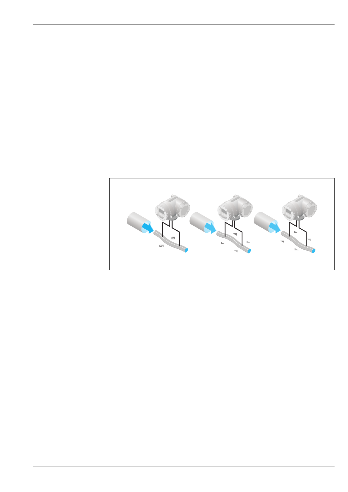
This causes the measuring tube loop through which the fluid is flowing to oscillate. The Coriolis forces
produced at the measuring tube loop cause a phase shift in the oscillations of the tube loop (see illustration):
• If there is zero flow, i.e. when the fluid stands still, the oscillation measured at points A and B has the same
phase, and thus there is no phase difference (1).
• Mass flow causes deceleration of the oscillation at the inlet of the tube loop (2) and acceleration at the
outlet (3).
A
B
A
B
A
B
12 3
A0003383
The phase difference (A-B) increases with increasing mass flow. Electrodynamic sensors register the tube loop
oscillations at the inlet and outlet.
Compared to two-tube systems, other design solutions are required in single-tube systems to ensure system
balance. In the case of the CNGmass DCI, an internal reference mass is provided for this purpose.
The measuring principle operates independently of temperature, pressure, viscosity, conductivity and flow
profile.
Density measurement
The measuring tube is continuously excited at its resonance frequency. A change in the mass and thus the
density of the oscillating system (comprising the measuring tube loop and fluid) results in a corresponding,
automatic adjustment in the oscillation frequency. Resonance frequency is thus a function of fluid density. The
microprocessor utilizes this relationship to obtain a density signal.
Temperature measurement
The temperature of the measuring tube loop is determined in order to calculate the compensation factor due
to temperature effects.
This signal corresponds to the process temperature and is also available as an output.
Endress+Hauser 3
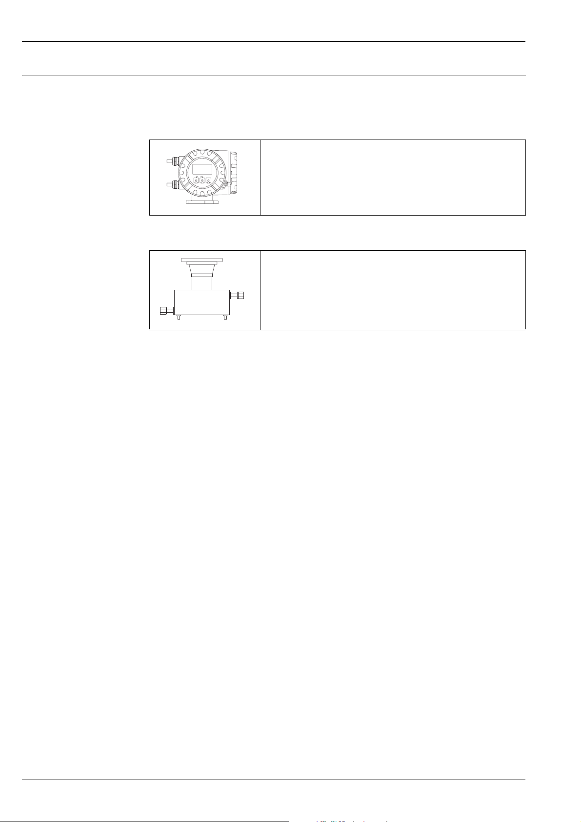
Measuring system The measuring system consists of a transmitter and a sensor. Two versions are available:
• Compact version: transmitter and sensor form a mechanical unit.
• Remote version: transmitter and sensor are mounted physically separate from one another.
Transmitter
• Four-line liquid crystal display
• Configuration via Touch Control, HART, MODBUS RS485, FieldCare
• Application-specific Quick Setup
Esc
–
+
E
• Mass flow, volume flow, density and temperature measurement as well as
calculated variables (e.g. fluid concentrations)
A0003672
Sensor
• Universal sensor for fluid temperatures up to 200 °C.
• Nominal diameters DN 1 to 6
• Tube material: stainless steel
Cubemass DCI
A0011878
4 Endress+Hauser
Cubemass DCI
Input
Measured variable • Mass flow (proportional to the phase difference between two sensors mounted on the measuring tube to
register a phase shift in the oscillation)
• Volume flow (calculated using mass flow and density)
• Fluid density (proportional to the resonance frequency of the measuring tube)
• Fluid temperature (measured with temperature sensors)
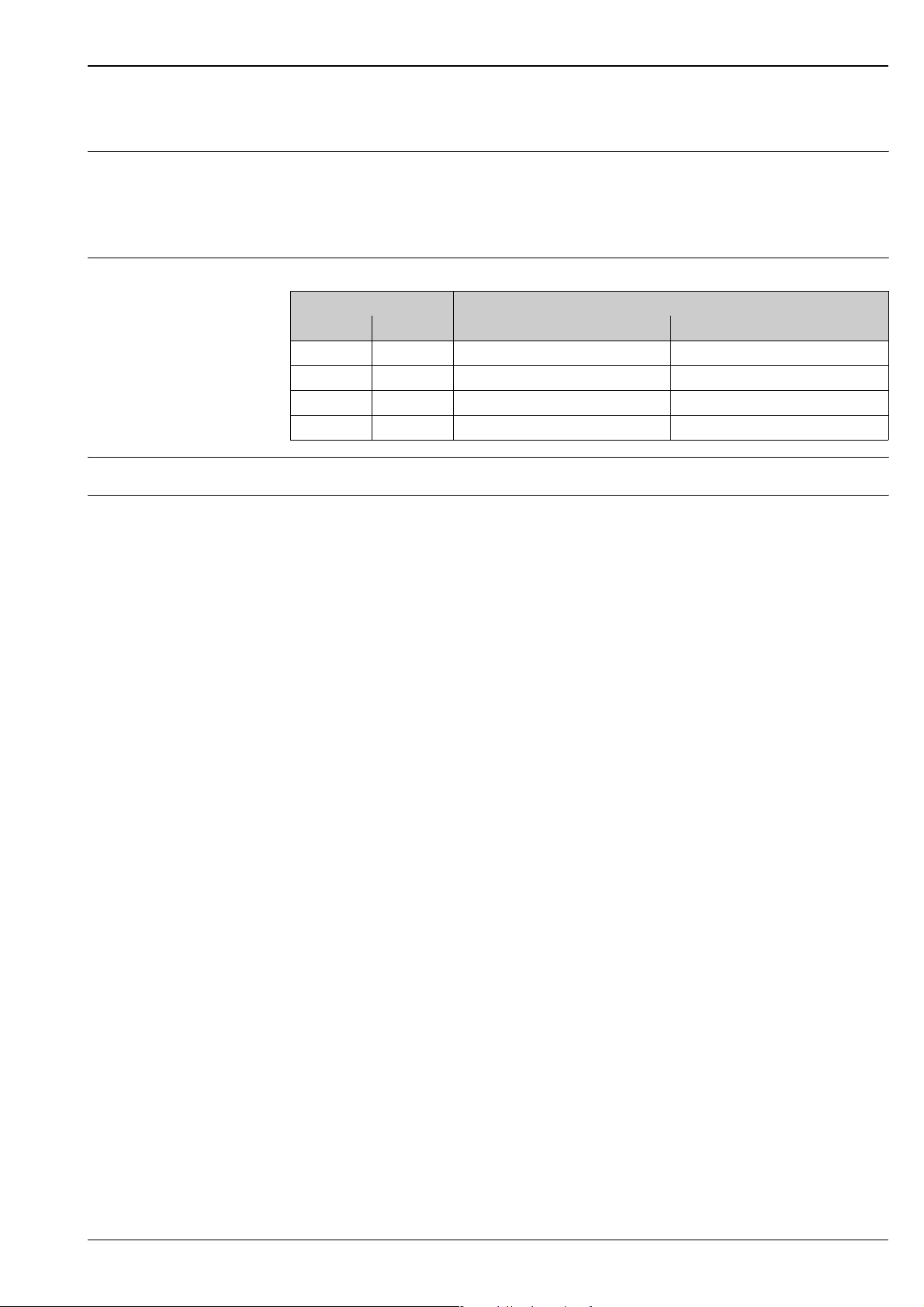
Measuring range Measuring ranges for liquids
DN Range for full scale values (liquids) g
[mm] [inch] [kg/h] [lb/min]
1 1/24" 0 to 20 0 to 0.75
2 1/12" 0 to 100 0 to 3.7
4 1/8" 0 to 450 0 to 16.5
6 ¼" 0 to 1000 0 to 37
Operable flow range 1:100
Input signal Status input (auxiliary input)
U = 3 to 30 V DC, R
= 5 kΩ, galvanically isolated.
i
Switching level: 3 to 30 V DC, polarity-independent.
Configurable for: totalizer reset, positive zero return, error message reset, start zero point adjustment.
min(F)
to g
max(F)
Endress+Hauser 5

Output
Output signal Current output
Active/passive selectable, galvanically isolated, time constant selectable (0.05 to 100 s),
full scale value selectable, temperature coefficient: typically 0.005% o.f.s. / °C, resolution: 0.5 μA
• Active: 0/4 to 20 mA, R
• Passive: 4 to 20 mA; supply voltage VS: 18 to 30 V DC; Ri ≥ 150 Ω
o.f.s. = of full scale value
Pulse/frequency output
Active/passive selectable, galvanically isolated
• Active: 24 V DC, 25 mA (max. 250 mA during 20 ms), RL > 100 Ω
• Passive: open collector, 30 V DC, 250 mA
• Frequency output: full scale frequency 2 to 10000 Hz (f
pulse width max. 2 s
• Pulse output: pulse value and pulse polarity selectable, pulse width configurable (0.05 to 2000 ms)
MODBUS RS485
• MODBUS device type: slave
• Address range: 1 to 247
• Supported function codes: 03, 04, 06, 08, 16, 23
• Broadcast: supported with the function codes 06, 16, 23
• Physical interface:
RS485 in accordance with EIA/TIA-485 standard
• Supported baud rate: 1200, 2400, 4800, 9600, 19200, 38400, 57 600, 115 200 Baud
• Transmission mode:
RTU or ASCII
• Response times:
Direct data access = typically 25 to 50 ms
Auto-scan buffer (data range) = typically 3 to 5 ms
• Possible output combinations È Operating Instructions
< 700 Ω, RL ≥ 250 Ω (HART)
L
= 12500 Hz), on/off ratio 1:1,
max
Cubemass DCI
Signal on alarm Current output
Failsafe mode selectable (for example, according to NAMUR Recommendation NE 43)
Pulse/frequency output
Failsafe mode selectable
Relay output
De-energized in the event of fault or power supply failure
MODBUS RS485
If an error occurs, the value NaN (not a number) is output for the process variables.
Switching output Relay output
Normally closed (NC or break) or normally open (NO or make) contacts available
(factory setting: relay 1 = normally open),
max. 30 V / 0.5 A AC; 60 V / 0.1 A DC, galvanically isolated.
Load È "Output signal"
Galvanic isolation All circuits for inputs, outputs, and power supply are galvanically isolated from each other.
6 Endress+Hauser
Cubemass DCI
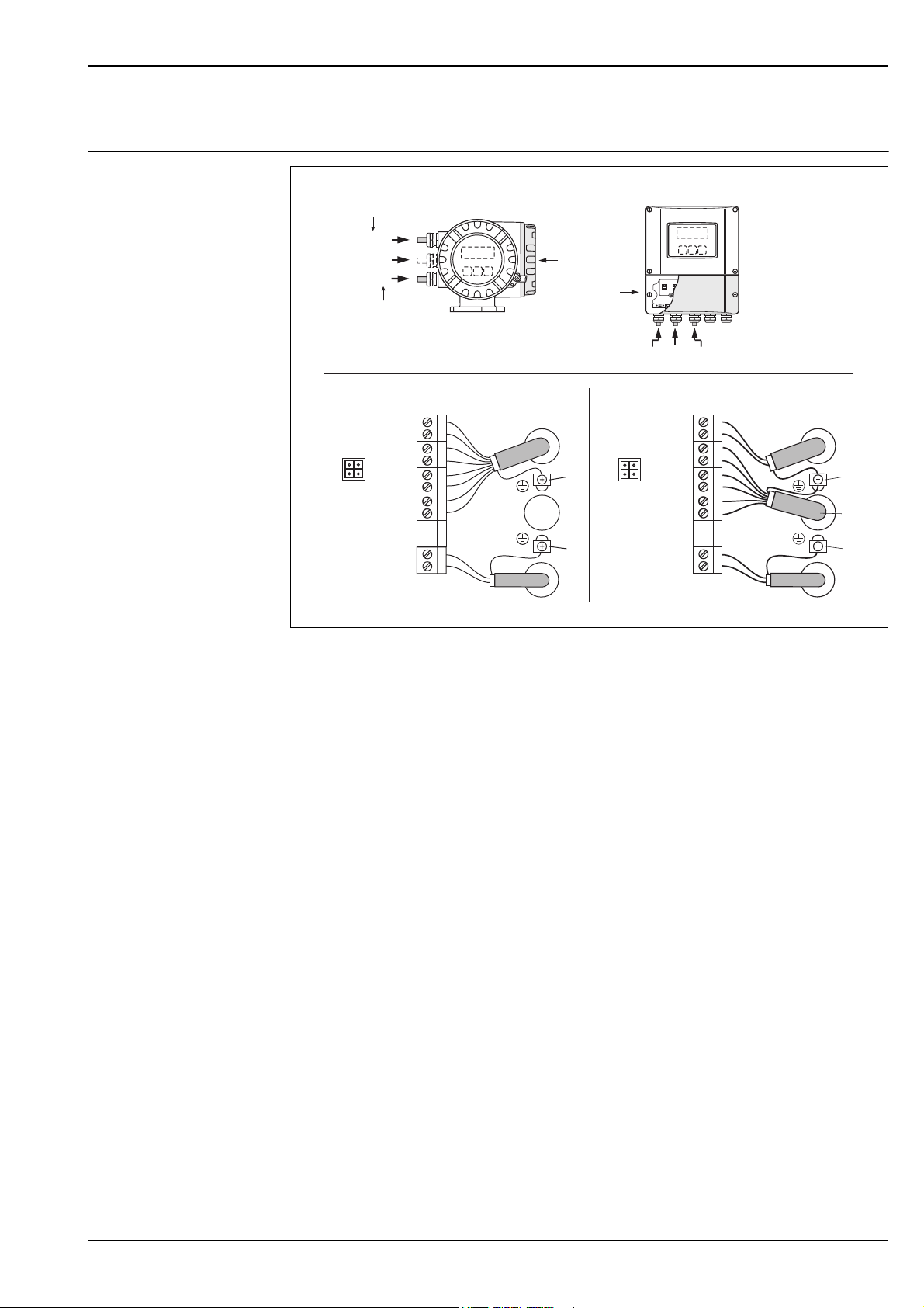
Electrical connection Measuring unit
Power supply
HART
b/c
–/b
a/a
MODBUS RS485
a/a
b/b
B
–/c
A
HART
–27
+26
–25
f
+24
–23
+22
–21
+20
N (L-) 2
L1 (L+) 1
A (RxD/TxD-N)
B (RxD/TxD-P)
b
e
d
f
MODBUS RS485
27
26
25
–
+
24
23
–
+
22
21
–
+
20
N (L-)
2
L1 (L+)
1
a
Connecting the transmitter, cable cross-section: max. 2.5 mm2 (14 AWG)
A View A (field housing)
B View B (wall-mount housing)
a Cable for power supply: 85 to 260 V AC, 20 to 55 V AC, 16 to 62 V DC
– Terminal No. 1: L1 for AC, L+ for DC
– Terminal No. 2: NN for AC, L- for DC
b Signal cable: Terminal assignment → ä 8
c Fieldbus cable
– Terminal No. 26: B (RxD/TxD-P)
– Terminal No. 27: A (RxD/TxD-N)
d Ground terminal for protective ground
e Ground terminal for signal cable shield/ fieldbus cable shield
Please note:
– shielding and grounding of fieldbus cable È Operating Instructions
– that the stripped and twisted lengths of cable shield to the ground terminal are as short as possible
f Service adapter for connecting service interface FXA193 (Fieldcheck, FieldCare)
c
e
b
d
a
A0012023
Endress+Hauser 7
Cubemass DCI
Electrical connection, terminal assignment
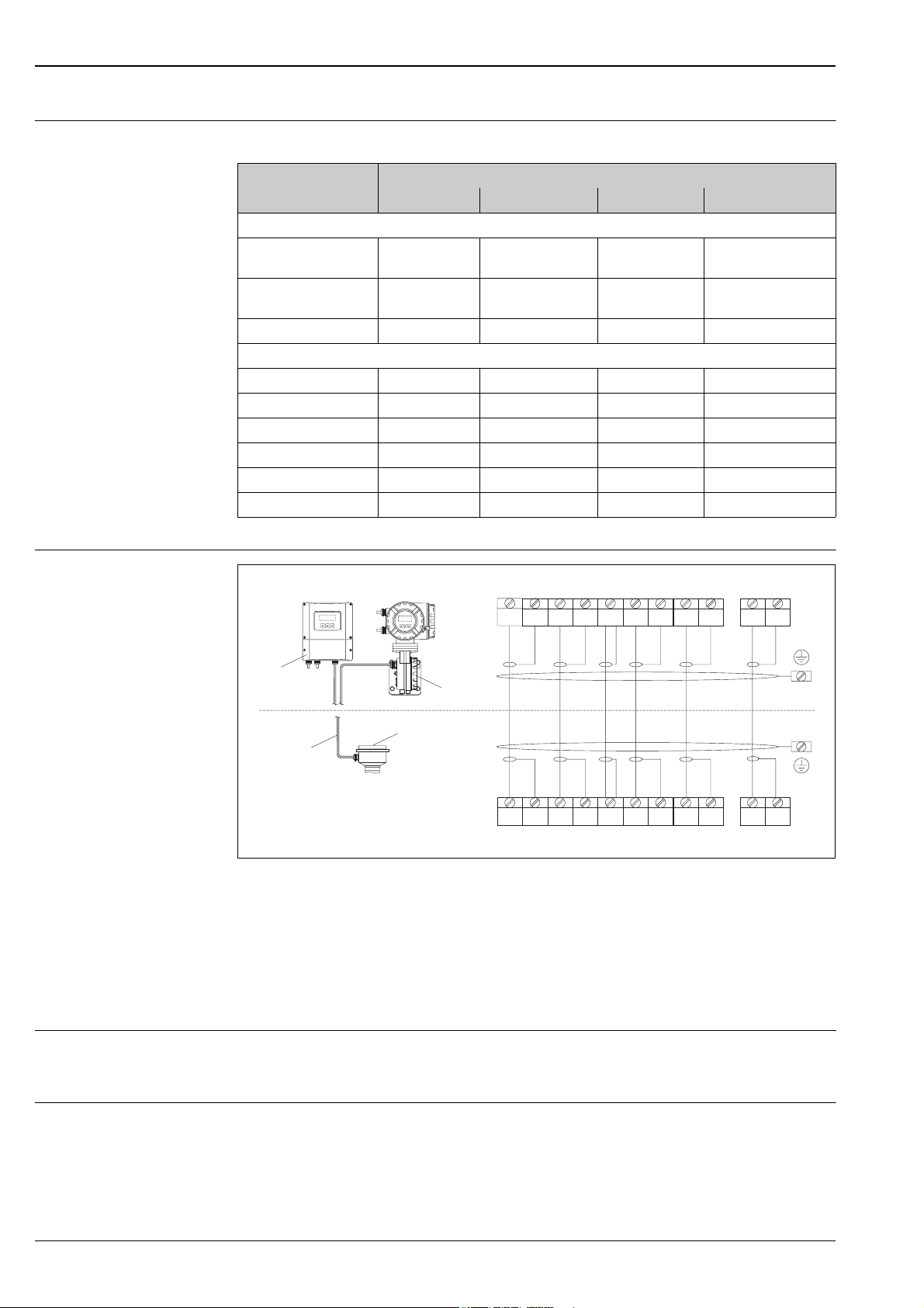
Electrical connection, Remote version
Electrical values for inputs/outputs È Operating Instructions
Terminal No. (inputs/outputs)
Order version 20 (+) / 21 (-) 22 (+) / 23 (-) 24 (+) / 25 (-) 26 (+) / 27 (–)
Fixed communication boards (permanent assignment)
8CN**–**S********* – –
8CN**–**T********* – –
8CN**–**Q********* – – Status input MODBUS RS485
Flexible communication boards
8CN**–**D********* Status input Relay output Frequency output Current output, HART
8CN**–**M********* Status input Frequency output 2 Frequency output 1 Current output, HART
8CN**–**N********* Current output Frequency output Status input MODBUS RS485
8CN**–**1********* Relay output Frequency output 2 Frequency output 1 Current output, HART
8CN**–**2********* Relay output Current output 2 Frequency output Current output 1, HART
8CN**–**7********* Relay output 2 Relay output 1 Status input MODBUS RS485
a
b
S1 S1 S2 S2 GND TM TM TT TT
++ ++
4 5 6 7 8 9 10 11 12 41 42
Frequency output,
Ex i, passive
Frequency output,
Ex i, passive
Current output, Ex i,
active, HART
Current output, Ex i,
passive, HART
d
d
d
e
c
Connecting the remote version
a Transmitter wall-mount housing: non-hazardous area → separate documentation
b Transmitter wall-mount housing: ATEX II2G / Zone 1 / NEC/CEC → separate Ex documentation
c Sensor connection housing
d Cover of connection compartment or connection housing
e Connecting cable
Terminal No.: 4/5 = gray; 6/7 = green; 8 = yellow; 9/10 = pink; 11/12 = white; 41/42 = brown
Supply voltage 85 to 260 V AC, 45 to 65 Hz
20 to 55 V AC, 45 to 65 Hz
16 to 62 V DC
Cable entries Power supply and signal cables (inputs/outputs):
• Cable entry M20 × 1.5 (8 to 12 mm / 0.31 to 0.47")
• Threads for cable entries, ½" NPT, G ½"
Connecting cable for remote version:
• Cable entry M20 × 1.5 (8 to 12 mm / 0.31 to 0.47")
• Threads for cable entries, ½" NPT, G ½"
4 5 6 7 8 9 10 11 12 41 42
++ ++
S1 S1 S2 S2 GND TM TM TT TT
A0003681
8 Endress+Hauser

Cubemass DCI
Cable specifications Any suitable cable with a temperature specification of at least 20 °C (68 °F) higher than the ambient
temperature of the application. We recommend the use of a cable with a temperature specification of +80 °C
(+176 °F).
Remote version:
2
(20 AWG) PVC cable with common shield and individually shielded cores
2
(AWG 22)
!
• 6 × 0.38 mm
• Conductor resistance: ≤ 50 Ω/km (≤ 0.015 Ω/ft)
• Capacitance core/shield: ≤ 140 pF/m (≤ 42.7 pF/ft)
• Cable length: max. 20 m (65.6 ft)
• Permanent operating temperature: max. +105 °C (+221 °F)
Note!
The cable must be installed securely, to prevent movement.
MODBUS RS485 (cable type A):
• Characteristic impedance: 135 to 165 Ω at a measuring frequency of 3 to 20 MHz
• Cable capacity: < 30 pF/m (< 9.2 pF/ft)
• Core cross-section: > 0.34 mm
• Cable type: twisted pairs
• Loop-resistance: ≤ 110 Ω/km (≤ 0.034 Ω/ft)
• Signal damping: max. 9 dB along the entire length of the cable cross-section
• Shield: Copper braided shielding or braided shielding and foil shielding
Power consumption AC: < 15 VA (including sensor)
DC: < 15 W (including sensor)
Switch-on current
• max. 13.5 A (< 50 ms) at 24 V DC
• max. 3 A (< 5 ms) at 260 V AC
Power supply failure Lasting min. 1 power cycle:
• EEPROM or HistoROM T-DAT saves measuring system data if power supply fails.
• HistoROM/S-DAT: exchangeable data storage chip which stores the data of the sensor (nominal diameter,
serial number, calibration factor, zero point etc.)
Potential equalization No measures necessary.
For explosion-protected equipment → separate Ex-documentation supplied
Endress+Hauser 9
Performance characteristics
Cubemass DCI
Reference operating conditions
• Error limits following ISO/DIS 11631
• Water, typically 20 to 30 °C (68 to 86 °F); 2 to 4 bar (30 to 60 psi)
• Data as per the calibration report ±5 °C (±9 °F) and ±2 bar (±30 psi)
• Data on the measured error based on accredited calibration rigs traced back to ISO 17025
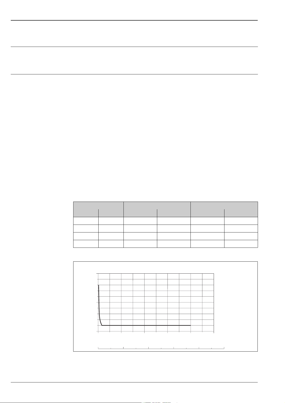
Maximum measured error The values indicated refer to the pulse/frequency output.
The additional measured error for the current output is typically ±5 μA. Basis for calculations → ä 11.
o.r. = of reading
Mass flow and volume flow (liquids)
• ±0.10% o.r. (mass flow)
• ±0.10% o.r. (volume flow)
Density (liquids)
• ±0.001 g/cc (after field density calibration or under reference conditions)
• ±0.002 g/cc (special density calibration (optional)
Calibration range: 0.0 to 2.0 g/cc, 5 to 80 °C (41 to 176 °F)
Application range: 0.0 to 5.0 g/cc, –50 to 200 °C (–58 to 392 °F)
• ±0.02 g/cc (standard calibration)
Temperature
±0.5 °C ± 0.005 · T °C
(±1.0 °F ± 0.003 · (T – 32) °F)
T = Fluid temperature
Zero point stability
DN Max. full scale value Zero point stability
[mm] [inch] [kg/h] [lb/min] [kg/h] [lb/min]
1 1/24" 0 to 20 0 to 0.75 0.0008 0.00003
2 1/12" 0 to 100 0 to 3.7 0.002 0.00007
4 1/8" 0 to 450 0 to 16.5 0.014 0.0005
6 ¼" 0 to 1000 0 to 37 0.02 0.0007
Example of maximum measured error
[%]
1.0
0.9
0.8
0.7
0.6
0.5
0.4
0.3
0.2
0.1
0
0
0.2
Max. measured error in % o.r. (example: Cubemass DCI, DN 1)
0.6
0.8
255101520
1.00.4
kg/h
lb/min0
A0011691
10 Endress+Hauser
 Loading...