

Page 1
TI01139C/07/EN/03.19
71440424
2019-03-01
Products Solutions Services
Technical Information
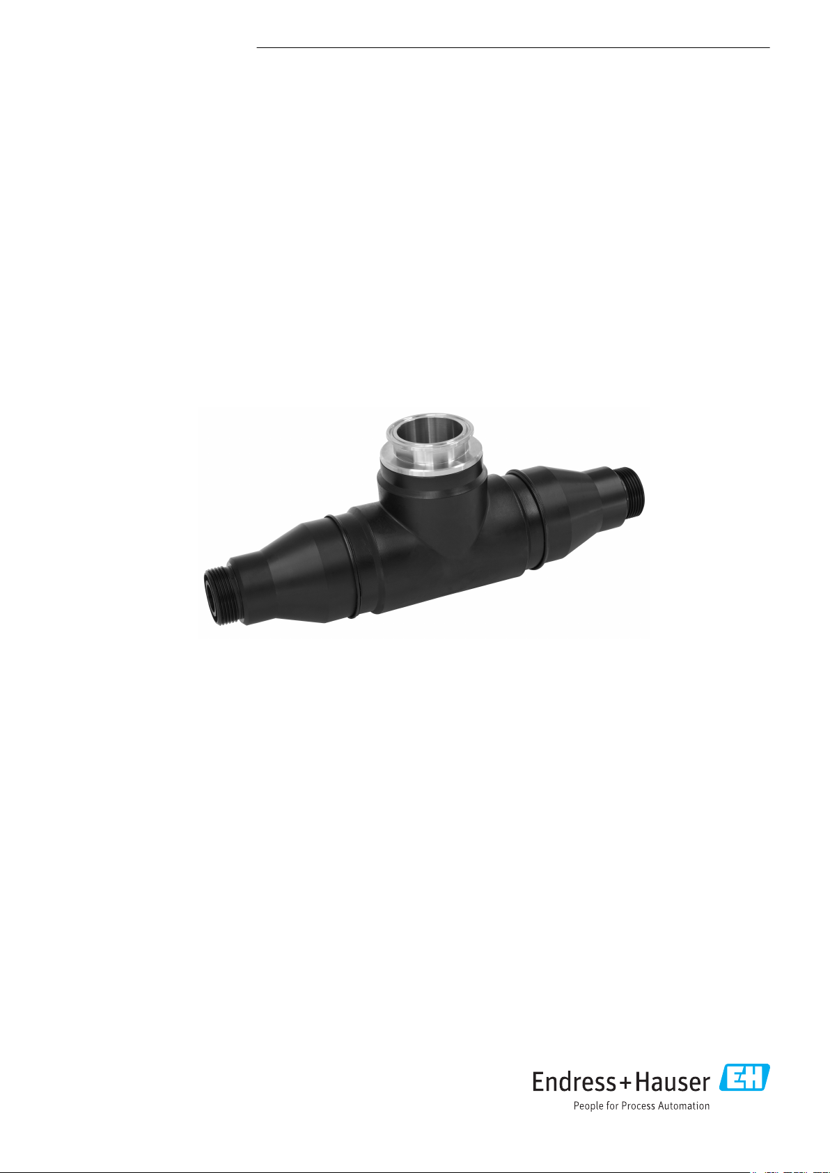
CUA252
Flow assembly for CUS52D turbidity sensor
Application
The CUA252 flow assembly is designed for the installation of
the CUS52D turbidity sensor. It can be used anywhere process
medium is conducted in pipelines or, following sampling, is
held in closed pipes.
• Turbidity measurement at all stages of the water treatment
process
• Final turbidity measurement in outlet of waterworks
• Turbidity measurement in inlet of waterworks
• Turbidity measurement for filter monitoring and filter
backwashing
• Turbidity measurement in drinking water networks
Your benefits
• Easy wall or pipe mounting
• Variable mounting
• Self-venting with vertical installation
• Suitable for use in drinking water thanks to PE100 material
Page 2
Function and system design
7
1
2
3
4
5
6
CUA252
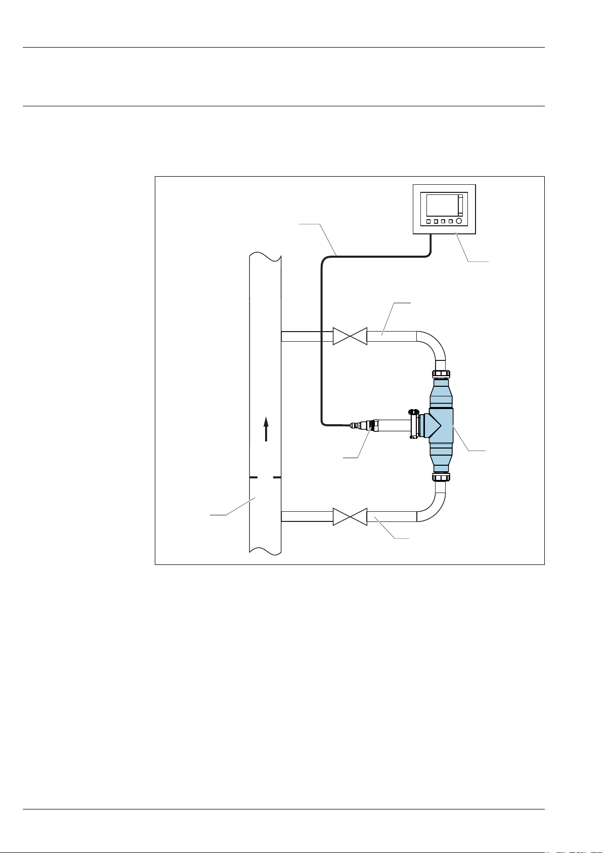
Measuring system
A complete measuring system comprises:
• Flow assembly Flowfit CUA252
• Sensor Turbimax CUS52D
• Transmitter, e.g. Liquiline CM442
• Measuring cable
1 Measuring system
1 Process pipe
2 Measuring cable
3 Liquiline CM442 transmitter
4 Return line with shut-off valve
5 Turbidity sensor CUS52D
6 Flow assembly CUA252
7 Inlet with shut-off valve
2 Endress+Hauser
A0022262
Page 3
CUA252
Installation instructions
Installation
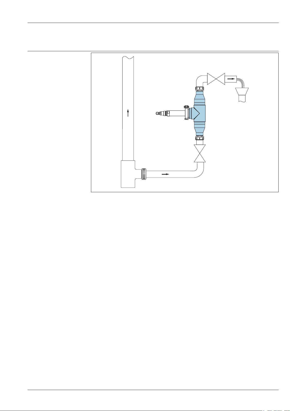
2 Connection example with open outlet
A0022259
Endress+Hauser 3
Page 4
CUA252
p1
p2
p1 > p2
1
A0022258
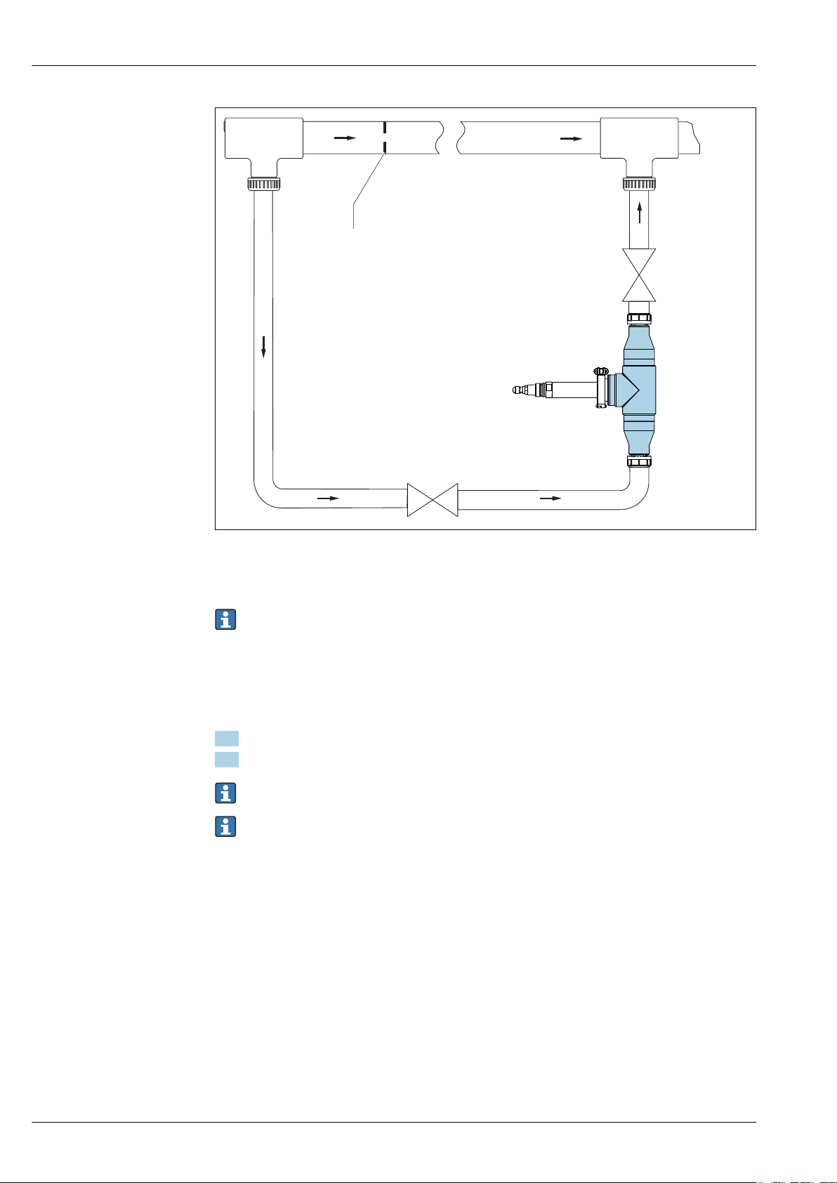
3 Connection example with bypass and orifice plate in the main pipe (supply from below)
1 Orifice plate
No measures to increase pressure are required for branch pipes (pipes that branch off from the
main pipe).
To achieve flow through the assembly with a bypass, pressure p1 must be higher than pressure p2.
Install the orifice plate in the main pipe → 3, 4.
‣
The inlet and outlet connection of the flow assembly are always identical. The system is symmetrical.
1. Install the flow assembly vertically.
2. Connect the inflow at the bottom end (upward flow in the pipe).
Avoid buckles and loops in the hose system.
Pay attention to the installation instructions (flow direction) for the sensor.
Many media tend to develop gas bubbles in a depressurized state. The operation of the flow
assembly under pressure (adjustable valve after the flow assembly) prevents this behavior in many
cases.
4 Endress+Hauser
Page 5
CUA252
291 (11.46)
1
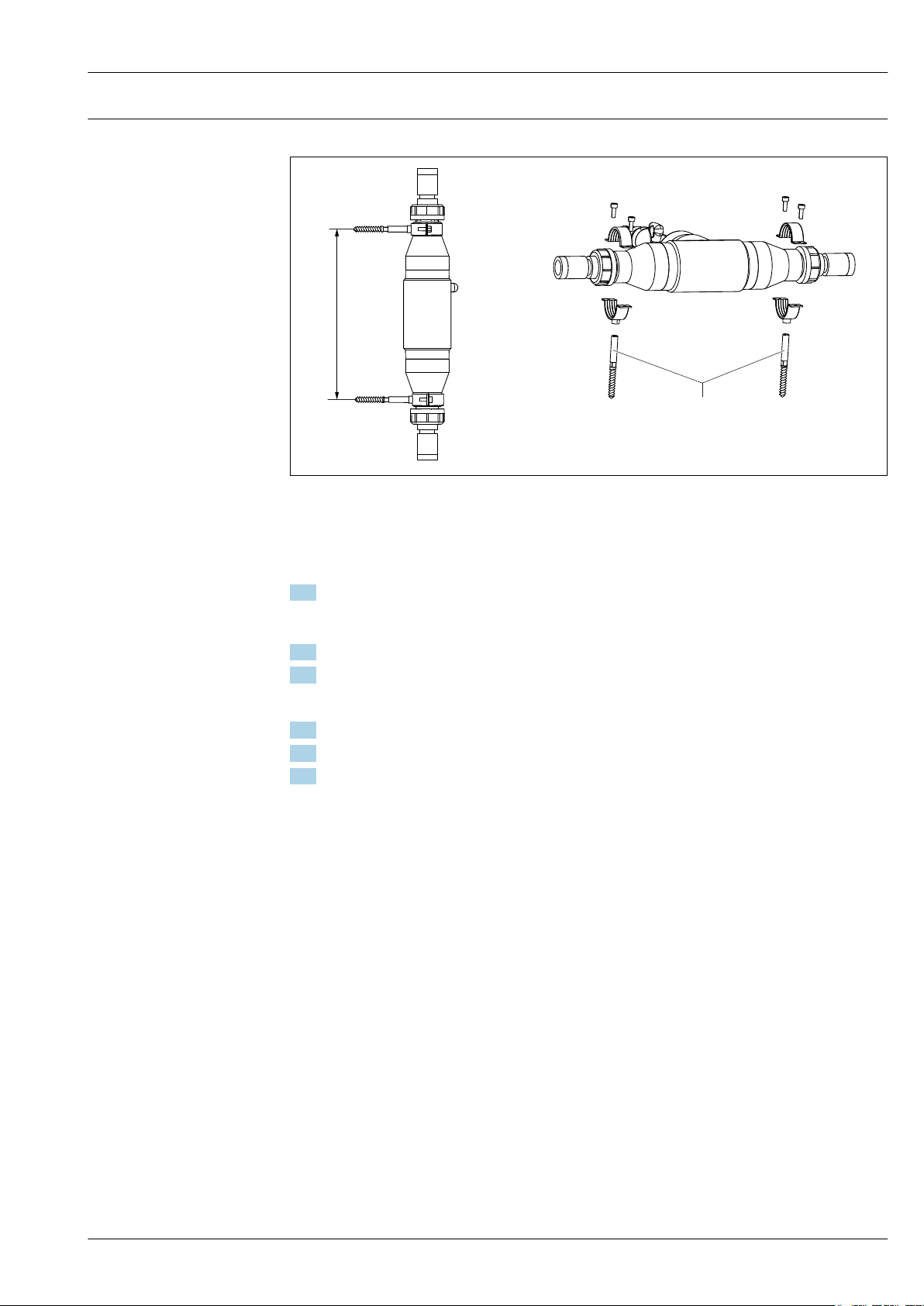
Mounting the flow assembly Mounting the assembly with wall holder unit
4 Wall holder unit. Engineering unit: mm (in)
1 Hanger bolt STST 10x60 (included in scope of delivery of wall mounting kit)
A0022264
Mounting the flow assembly in a bypass
1. Install a shut-off valve upstream and downstream from the flow assembly in the bypass line.
This makes it possible to perform maintenance tasks, such as the cleaning of the sensor,
without affecting the process.
2. Mount the assembly vertically.
3. Establish the medium connection using commercially available connection fittings.
Mounting the flow assembly in a branch pipe with an open outlet
1. Install a shut-off valve upstream from the flow assembly.
2. Mount the assembly vertically.
3. Establish the medium connection using commercially available connection fittings.
Endress+Hauser 5
Page 6

Mounting the assembly with a bubble trap
1
2
3
4
5
6
7
8
9
10
CUA252
A0035917
5 Connection example with bubble trap
1 Inlet from below
2 Shutoff valve
3 Bubble trap
4 Venting of bubble trap (included in scope of delivery)
5 Shut-off valve (throttle for increasing pressure)
6 Outlet
7 D 12 adapter with connection for vent pipe (included in scope of delivery)
8 Flow assembly CUA252
9 Turbidity sensor CUS52D
10 D 12 adapter
The wastewater from the bubble trap is not suitable for feeding back into the process.
1. For the hose system, use PVC hoses with an internal diameter of 12 mm (0.5 in).
2. Secure the hose system using worm drive hose clips (not included in scope of delivery).
The inlet and outlet connection of the flow assembly are always identical. The system is symmetrical.
Mounting the flow assembly
1. Install the flow assembly vertically. The inflow must be connected at the bottom end (upward
flow in the pipe).
2. Insert an orifice plate into the upper assembly connection to obtain the desired volume flow
(included in the delivery).
6 Endress+Hauser
Page 7

CUA252
10
11
12
13
1
2
3
Mounting the sensor
Orifice plates:
• 1 mm (0.04 in) for volume flow < 60 l/h (15.8 gal/h)
• 3 mm (0.12 in) for volume flow 60 to 100 l/h (15.8 to 26.4 gal/h)
• 5 mm (0.2 in) for volume flow > 100 l/h (26.4 gal/h)
Avoid buckles and loops in the hose system.
Pay attention to the installation instructions (flow direction) for the sensor .
Note the maximum pressure and maximum temperature when operating the bubble trap
→ 8.
Ambient temperature range
Storage temperature
7 Sensor orientation
A0035918
6 Sensor installation
10 Flow assembly CUA252
11 Clamp seal
12 Locking clamp
13 Turbidity sensor CUS52D
1 Optical windows
2 Direction of flow
3 Installation marking
Only insert turbidity sensors into the assembly with a 2" clamp.
1. Install the sensor in such a way that the optical windows of the sensor are aligned against the
direction of flow (item 2).
2. Use the installation marking (item 3) on the sensor to ensure the correct sensor orientation.
Environment
0 to 55 °C (32 to 131 °F)
0 to 60 °C (32 to 140 °F), in the original packaging
A0035919
Process
Process temperature range
Process pressure range
Endress+Hauser 7
0 to 60 °C (32 to 140 °F)
0 to 6 bar (0 to 87 psi)
Page 8

Pressure/temperature
p [bar]
T[°C]
10 4030
4
20
T[°F]
p [psi]
58
0
32
0
0
6
87
50 60
50
68 86
104
122
140
p [bar]
T[°C]
10 4030
3
20
T[°F]
p [psi]
43,5
0
32
0
0
50
50
68 86
104
122
ratings
CUA252
A0035922
8 Pressure/temperature ratings
Flow velocity
Flow limit
Pressure loss
A0039233
9 Pressure/temperature ratings for bubble trap
Max. 2 m/s (6.6 ft/s) for low-viscosity media in pipes NW 50
Recommended flow: 60 l/h (15.8 gal/h)
Range: 10 to 100 l/h (2.64 to 26.4 gal/h)
If operating with lost sample (water loss)
< 0.05 bar (0.7 psi) for flow up to 100 l/h (26.4 gal/h)
8 Endress+Hauser
Page 9

CUA252
X X
Y
Y
105
(4.13)
50
(1.97)
Ø 81.5
(3.21)
124
(4.88)
197 (7.76)
350 (13.78)
Ø 75
(2.95)
Ø 50 (1.97)
Ø 81.5
(3.21)
Dimensions
Mechanical construction
A0022255
10 Dimensions. Engineering unit: mm (in)
Connections NPT ¾" Rp ¾ Glue-in port D25ANSI 2" Hose D 25 Hose D 12 G1 ¾
X mm (in) 70 (2.76) 64 (2.52) 22 (0.87) 71 (2.80) 74 (2.91) 74 (2.91) 0
Y mm (in) Ø 58(2.28) Ø 58(2.28) Ø 58(2.28) Ø 152
(5.98)
Weight
Materials
1.17 kg (2.58 lb) without process connection
Assembly housing: PE100
Seals: EPDM
Flange: PP-GF
Dummy cover: Stainless steel 1.4404 (AISI 316 L)
Bubble trap: Polycarbonate
Process connections: PE
Process connection for bubble trap: PVC
Ø 58(2.28) Ø 58(2.28) Ø 58(2.28)
Endress+Hauser 9
Page 10
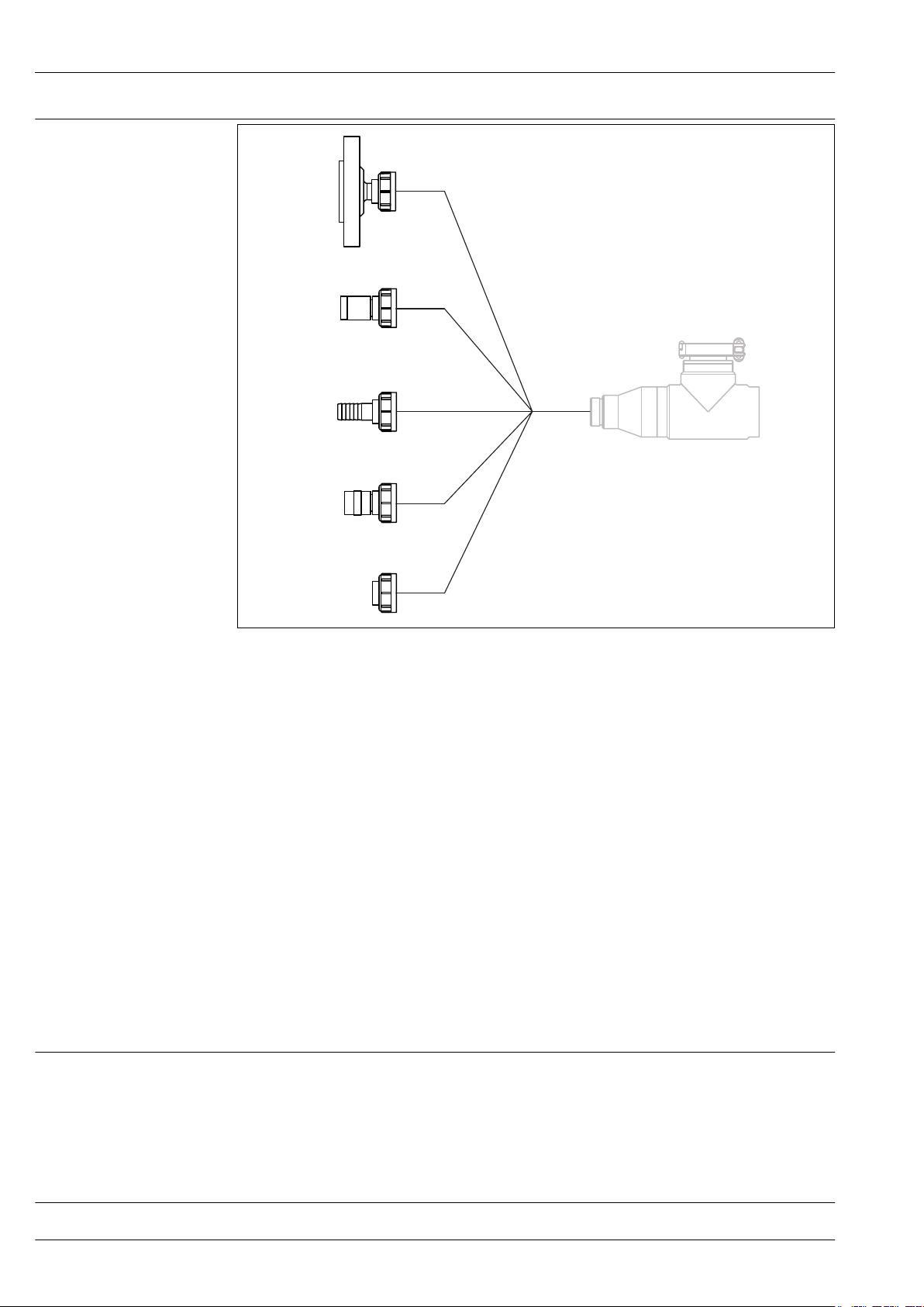
Process connections
B2
B3
C1
D1
E2
CUA252
Scope of delivery
Product page
A0035923
11 Process connections
B2 Internal thread Rp ¾"
B3 Internal thread NPT ¾"
C1 Glue-in port D 25
D1 Hose D 25
E2 Flange ANSI 2"
It is also possible to use an external thread G1 ¼ (standard) or a D 12 hose.
Certificates and approvals
DRGL- 2014/68/EU / PED- 2014/68/EU
The assembly has been manufactured according to good engineering practice as per Article 4,
Paragraph 3 of the Pressure Equipment Directive 2014/68/EU and is therefore not required to bear
the CE label.
Ordering information
The scope of delivery comprises:
• 1 Flowfit CUA252 flow assembly, version as ordered
• 1 clamp seal and locking clamp
• 2 process connections, version as ordered
• 1 set of Operating Instructions
If you have any queries:
‣
Please contact your supplier or local sales center.
www.endress.com/cua252
10 Endress+Hauser
Page 11

CUA252
Product Configurator
On the product page there is a Configure button to the right of the product image.
1. Click this button.
The Configurator opens in a separate window.
2. Select all the options to configure the device in line with your requirements.
In this way, you receive a valid and complete order code for the device.
3. Export the order code as a PDF or Excel file. To do so, click the appropriate button on the right
above the selection window.
For many products you also have the option of downloading CAD or 2D drawings of the
selected product version. Click the CAD tab for this and select the desired file type using
picklists.
Accessories
The following are the most important accessories available at the time this documentation was
issued.
For accessories not listed here, please contact your Service or Sales Center.
‣
Description Order number
Dummy cover for clamp connection; 1 pc 71242180
Adapter, internal thread, RP ¾", material: PE; 1 pc 71242172
Adapter, internal thread, NPT ¾", material: PE; 1 pc 71242173
Adapter, welded connection, D 25, material: PE; 1 pc 71242174
Adapter, hose connection nipple, D 25, material: PE; 1 pc 71242175
Adapter, hose connection nipple, D 12, material: PE; 1 pc 71242176
Adapter, flange ANSI 2", 1 pc 71242177
Ultrasonic cleaning system CYR52
• For attachment to assemblies and pipes
• Product Configurator on the product page: www.endress.com/cyr52
Technical Information TI01153C
Bubble trap
• For the CUS52D sensor
• Process pressure: up to 3 bar (43.5 psi)
• Process temperature: 0 to 50 °C (32 to 122 °F)
• D 12 adapter with connection for degassing line (upper connection on the CUA252) is included in
the scope of delivery.
• Orifice plates for the following volume flows:
• < 60 l/h (15.8 gal/h)
• 60 to 100 l/h (15.8 to 26.4 gal/h)
• > 100 l/h (26.4 gal/h)
• The degassing line is fitted with a PVC hose, backpressure hose valve and luer lock adapter.
• Order number, suitable for CUA252 assembly: 71242170
Endress+Hauser 11
Page 12

254 (10.0)
12 (0.5)
12 (0.5)
1
2
3
12 Bubble trap. Engineering unit: mm (in)
291 (11.46)
1
1 Inlet for medium (without hose system)
2 Outlet for bubbles (hose system is included in scope of delivery)
3 Outlet for medium (without hose system)
Wall mounting kit for CUA252
Order number: 71242171
CUA252
A0035757
13 Wall mounting kit. Engineering unit: mm (in)
1 Hanger bolt STST 10 x 60 mm (included in scope of delivery)
A0022264
12 Endress+Hauser
Page 13

Page 14

Page 15

Page 16

www.addresses.endress.com
 Loading...