

Endress+Hauser Cerabar T PMC131, Cerabar T PMP131, Cerabar T PMP135 Technical Information
TI415P/00/en
Technical Information
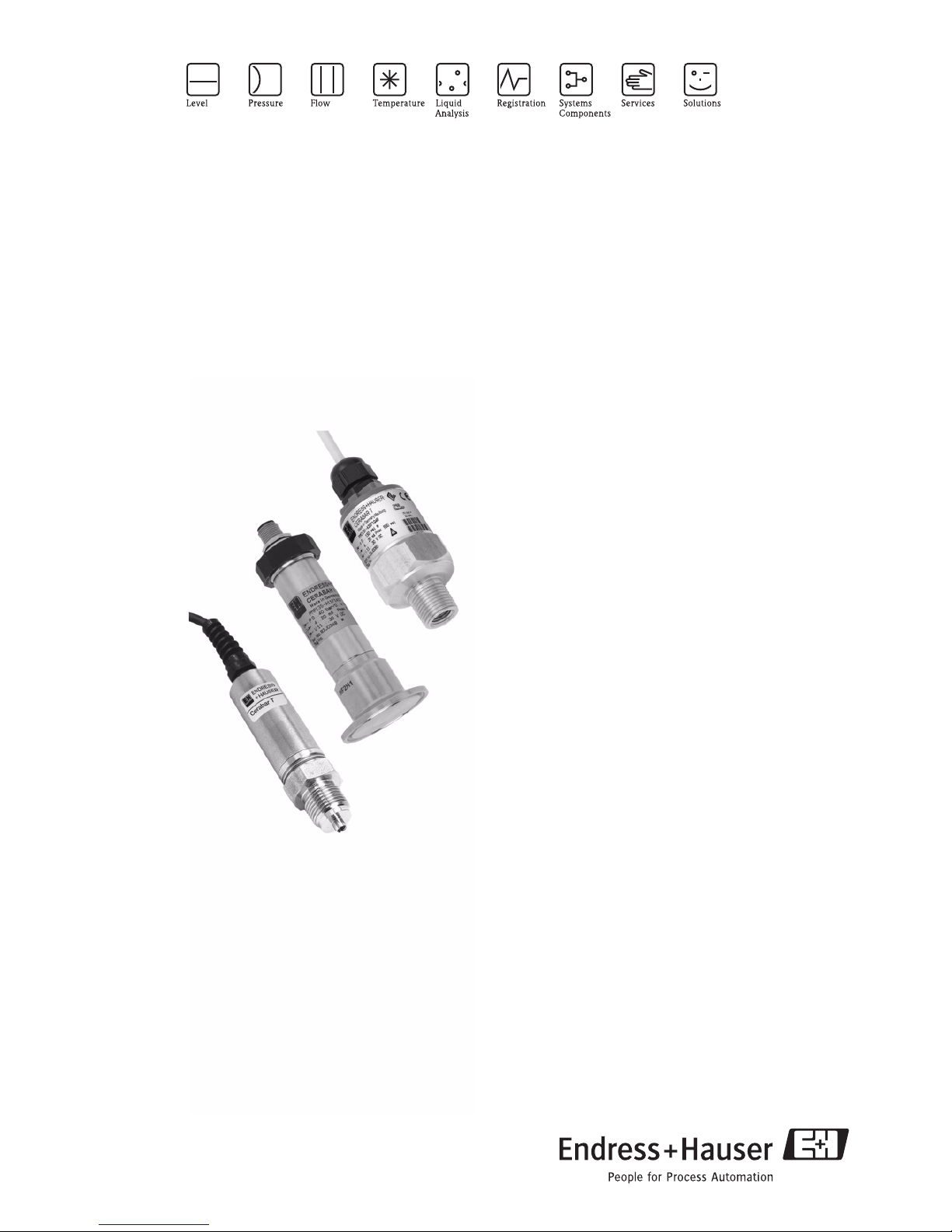
Cerabar T PMC131, PMP131, PMP135
Pressure Transducer
With ceramic and metal sensors
For absolute pressure and gauge pressure measurement up to 400 bar
Extremely stable, overload-resistant and reliable
Application
Cerabar T is a pressure transducer for measuring absolute
pressure and gauge pressure in gases, vapors, liquids and
dusts.
Hygienic and threaded connections are available as
process connections.
Your benefits
This compact pressure transducer impresses with its
well-engineered construction:
• High reproducibility and long-term stability.
• Finely graduated measuring ranges from vacuum up to
400 bar/6000 psi.
•Ceraphire
®
ceramic sensor: corrosion-proof, abrasion-
proof and extremely overload-resistant.
• Deployed for pressure monitoring up to SIL 2 as per
IEC 61508/IEC 61511-1
•Sensors
– Dry capacitance ceramic sensor (Ceraphire
®
) for
measuring ranges up to 40 bar:
overload-resistant, vacuum-proof, stable against
alternating load
– Piezoresistive sensor with metal diaphragm for
measuring ranges up to 400 bar

Cerabar T
2 Endress+Hauser
Table of contents
Function and system design. . . . . . . . . . . . . . . . . . . . . 3
Device selection . . . . . . . . . . . . . . . . . . . . . . . . . . . . . . . . . . . . . . 3
Measuring principle . . . . . . . . . . . . . . . . . . . . . . . . . . . . . . . . . . . 3
Measuring system . . . . . . . . . . . . . . . . . . . . . . . . . . . . . . . . . . . . . 4
Input . . . . . . . . . . . . . . . . . . . . . . . . . . . . . . . . . . . . . . 4
Measured variable . . . . . . . . . . . . . . . . . . . . . . . . . . . . . . . . . . . . 4
Measuring range . . . . . . . . . . . . . . . . . . . . . . . . . . . . . . . . . . . . . 4
Output . . . . . . . . . . . . . . . . . . . . . . . . . . . . . . . . . . . . . 4
Output signal . . . . . . . . . . . . . . . . . . . . . . . . . . . . . . . . . . . . . . . . 4
Load . . . . . . . . . . . . . . . . . . . . . . . . . . . . . . . . . . . . . . . . . . . . . . 4
Output signal . . . . . . . . . . . . . . . . . . . . . . . . . . . . . . . . . . . . . . . . 4
Output current . . . . . . . . . . . . . . . . . . . . . . . . . . . . . . . . . . . . . . . 4
Power . . . . . . . . . . . . . . . . . . . . . . . . . . . . . . . . . . . . . . . . . . . . . 5
Switch frequency . . . . . . . . . . . . . . . . . . . . . . . . . . . . . . . . . . . . . 5
Input PLC . . . . . . . . . . . . . . . . . . . . . . . . . . . . . . . . . . . . . . . . . . 5
Inductive loads . . . . . . . . . . . . . . . . . . . . . . . . . . . . . . . . . . . . . . . 5
Power supply . . . . . . . . . . . . . . . . . . . . . . . . . . . . . . . . 5
PMC131 . . . . . . . . . . . . . . . . . . . . . . . . . . . . . . . . . . . . . . . . . . . 5
PMP131 and PMP135 . . . . . . . . . . . . . . . . . . . . . . . . . . . . . . . . . 6
PMP131 . . . . . . . . . . . . . . . . . . . . . . . . . . . . . . . . . . . . . . . . . . . 7
Supply voltage . . . . . . . . . . . . . . . . . . . . . . . . . . . . . . . . . . . . . . . 7
Residual ripple . . . . . . . . . . . . . . . . . . . . . . . . . . . . . . . . . . . . . . . 7
Cable entry . . . . . . . . . . . . . . . . . . . . . . . . . . . . . . . . . . . . . . . . . 7
Performance characteristics. . . . . . . . . . . . . . . . . . . . . 8
Reference operating
conditions . . . . . . . . . . . . . . . . . . . . . . . . . . . . . . . . . . . . . . . . . . 8
Long-term stability . . . . . . . . . . . . . . . . . . . . . . . . . . . . . . . . . . . . 8
Maximum measured error
of analog output
(under reference operating conditions) . . . . . . . . . . . . . . . . . . . . . 8
Switch point . . . . . . . . . . . . . . . . . . . . . . . . . . . . . . . . . . . . . . . . . 8
Rise time (T90) . . . . . . . . . . . . . . . . . . . . . . . . . . . . . . . . . . . . . . 8
Settling time . . . . . . . . . . . . . . . . . . . . . . . . . . . . . . . . . . . . . . . . . 8
Thermal change of the lower range value and the span . . . . . . . . . 9
Temperature coefficient (TK) for lower range value and span . . . . . 9
Operating conditions (Installation instructions). . . . . . 9
Orientation . . . . . . . . . . . . . . . . . . . . . . . . . . . . . . . . . . . . . . . . . 9
Installation instructions . . . . . . . . . . . . . . . . . . . . . . . . . . . . . . . . . 9
Location dependence . . . . . . . . . . . . . . . . . . . . . . . . . . . . . . . . . . 9
Operating conditions (environment) . . . . . . . . . . . . . 10
Ambient temperature range . . . . . . . . . . . . . . . . . . . . . . . . . . . . 10
Storage temperature range . . . . . . . . . . . . . . . . . . . . . . . . . . . . . 10
Climate class . . . . . . . . . . . . . . . . . . . . . . . . . . . . . . . . . . . . . . . 10
Degree of protection . . . . . . . . . . . . . . . . . . . . . . . . . . . . . . . . . . 10
Vibration resistance . . . . . . . . . . . . . . . . . . . . . . . . . . . . . . . . . . 10
Electromagnetic compatibility . . . . . . . . . . . . . . . . . . . . . . . . . . . 10
Operating conditions (process) . . . . . . . . . . . . . . . . . 11
Process temperature range . . . . . . . . . . . . . . . . . . . . . . . . . . . . . 11
Overload resistance . . . . . . . . . . . . . . . . . . . . . . . . . . . . . . . . . . 11
Vacuum resistance . . . . . . . . . . . . . . . . . . . . . . . . . . . . . . . . . . . 11
Pressure specifications . . . . . . . . . . . . . . . . . . . . . . . . . . . . . . . . 11
Mechanical construction . . . . . . . . . . . . . . . . . . . . . . 12
PMC131 . . . . . . . . . . . . . . . . . . . . . . . . . . . . . . . . . . . . . . . . . . 12
PMP131 and PMP135 . . . . . . . . . . . . . . . . . . . . . . . . . . . . . . . . 13
PMP131 . . . . . . . . . . . . . . . . . . . . . . . . . . . . . . . . . . . . . . . . . . 13
PMP135 . . . . . . . . . . . . . . . . . . . . . . . . . . . . . . . . . . . . . . . . . . 14
Weights . . . . . . . . . . . . . . . . . . . . . . . . . . . . . . . . . . . . . . . . . . . 15
Material . . . . . . . . . . . . . . . . . . . . . . . . . . . . . . . . . . . . . . . . . . . 15
Operating elements . . . . . . . . . . . . . . . . . . . . . . . . . . 15
Operating elements . . . . . . . . . . . . . . . . . . . . . . . . . . . . . . . . . . 15
Certificates and approvals . . . . . . . . . . . . . . . . . . . . . 17
CE mark . . . . . . . . . . . . . . . . . . . . . . . . . . . . . . . . . . . . . . . . . . 17
Ex approvals . . . . . . . . . . . . . . . . . . . . . . . . . . . . . . . . . . . . . . 17
Pressure Equipment Directive (PED) . . . . . . . . . . . . . . . . . . . . . 17
Functional safety SIL 2 . . . . . . . . . . . . . . . . . . . . . . . . . . . . . . . . 17
Suitability for hygenic processes . . . . . . . . . . . . . . . . . . . . . . . . . 17
TSE Certificate of Suitability . . . . . . . . . . . . . . . . . . . . . . . . . . . . 17
Standards and guidelines . . . . . . . . . . . . . . . . . . . . . . . . . . . . . . 17
Registered trademarks . . . . . . . . . . . . . . . . . . . . . . . . . . . . . . . . 17
Ordering information. . . . . . . . . . . . . . . . . . . . . . . . . 18
PMC131 . . . . . . . . . . . . . . . . . . . . . . . . . . . . . . . . . . . . . . . . . . 18
PMC131 (continued) . . . . . . . . . . . . . . . . . . . . . . . . . . . . . . . . . 19
PMP131 . . . . . . . . . . . . . . . . . . . . . . . . . . . . . . . . . . . . . . . . . . 20
PMP131 (continued) . . . . . . . . . . . . . . . . . . . . . . . . . . . . . . . . . 21
PMP135 . . . . . . . . . . . . . . . . . . . . . . . . . . . . . . . . . . . . . . . . . . 22
Accessories . . . . . . . . . . . . . . . . . . . . . . . . . . . . . . . . 23
Welding neck with
sealing taper . . . . . . . . . . . . . . . . . . . . . . . . . . . . . . . . . . . . . . . 23
Welding neck with
sealing surface . . . . . . . . . . . . . . . . . . . . . . . . . . . . . . . . . . . . . . 23
Plug-in jack . . . . . . . . . . . . . . . . . . . . . . . . . . . . . . . . . . . . . . . . 23
Plug-on display
PHX20/PHX21 . . . . . . . . . . . . . . . . . . . . . . . . . . . . . . . . . . . . . 23
Documentation . . . . . . . . . . . . . . . . . . . . . . . . . . . . . 24
Field of Activities . . . . . . . . . . . . . . . . . . . . . . . . . . . . . . . . . . . . 24
Technical Information . . . . . . . . . . . . . . . . . . . . . . . . . . . . . . . . 24
Operating Instructions . . . . . . . . . . . . . . . . . . . . . . . . . . . . . . . . 24
Functional Safety Manual (SIL) . . . . . . . . . . . . . . . . . . . . . . . . . 24
Safety Instructions . . . . . . . . . . . . . . . . . . . . . . . . . . . . . . . . . . . 24
Cerabar T
Endress+Hauser 3
Function and system design
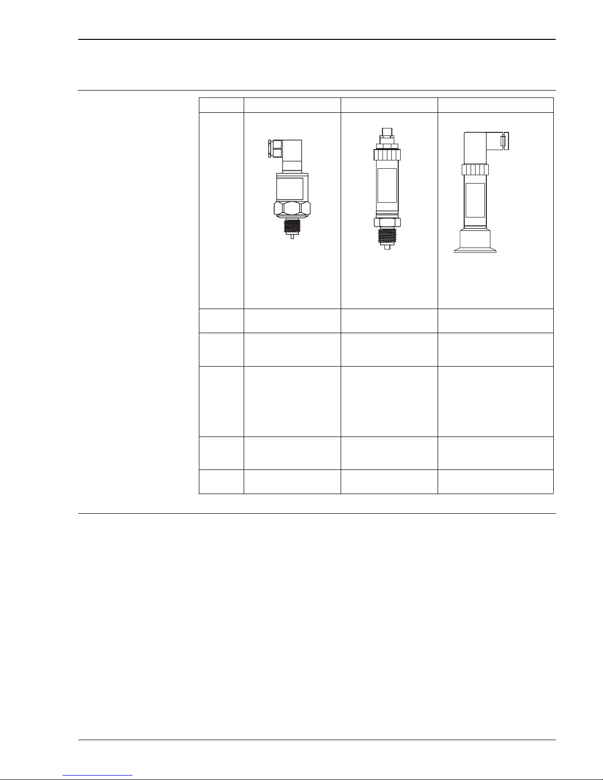
Device selection
Measuring principle PMC131
The measuring pressure causes a slight deflection of the ceramic diaphragm of the sensor. The pressureproportional change in capacitance is measured at the electrodes of the ceramic sensor. The ceramic sensor is
a dry sensor, i.e. no fill fluid is required for the pressure transfer. This makes the sensor completely suitable for
vacuums. Extremely high stability, comparable with the material Alloy, is achieved by using ultrapure
Ceraphire® as the ceramic.
PMP131 and PMP135 with analog output
The process pressure acting upon the metallic separating diaphragm of the sensor is transmitted to a resistance
bridge via a fluid. The pressure-proportional change of the bridge output voltage is measured and processed
further.
PMP131 and PMP135 with switch output
The process pressure acting upon the metallic separating diaphragm of the sensor is transmitted to a resistance
bridge via a fluid. A differential amplifier creates a standard signal from the pressure-proportional change in
output voltage of the bridge. A comparator with an adjustable hysteresis compares this signal with the pre-set
switch point and then activates the transistor output.
Cerabar T PMC131 PMP131 PMP135
P01-PMC131xx-14-xx-xx-xx-000 P01-PMP131xx-14-xx-xx-xx-000 P01-PMP135xx-14-xx-xx-xx-000
With capacitive measuring
cell and ceramic measuring
diaphragm (Ceraphire
®
)
With piezoresistive
measuring cell and metallic
measuring diaphragm
With piezoresistive measuring cell
and metallic measuring
diaphragm for hygienic
applications
Field of
application
Absolute pressure and gauge
pressure
Absolute pressure and gauge
pressure
Absolute pressure and gauge pressure
in hygienic processes
Output Current output 4 to 20 mA – Current output 4 to 20 mA
– Voltage output 0 to 10 V
– Switch output PNP
–4 to 20 mA
– Switch output PNP
Process
connection
Thread:
–G ½
– ½ MNPT and ¼ FNPT
– G ½, bore 11 mm
Thread:
–G ½
– ½ MNPT and ¼ FNPT
– ½ MNPT, bore 4 mm
–G ¼
– ¼ MNPT, bore 3.5 mm
– M 20 x 1.5
Hygiene:
– Clamp DN 22 (¾")
– Tri-Clamp DN 25 to 38 (1" to 1½")
– Tri-Clamp DN 40 to 51 (2")
–G 1
– SMS 1½"
Measuring
range
–1 to 0 bar/–100 to 0 kPa
up to
0 to 40 bar/0 to 4 MPa
0 to 1 bar/0 to 100 kPa
up to
0 to 400 bar/0 to 40 MPa
0 to 1 bar/0 to 100 kPa
up to
0 to 40 bar/0 to 4 MPa
Process
temperature
–20 to +100 °C –25 °C to +70 °C –25 to +100 °C
(+135 °C for max. 1 hour)
ENDRESS+HAUSER
CERABART
ENDRESS+HAUSER
CERABART
ENDRESS+HAUSER
CERABART
Cerabar T
4 Endress+Hauser
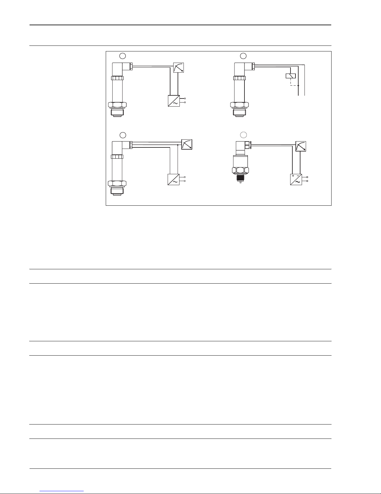
Measuring system
P01-PMx13xxx-14-xx-xx-xx-002
1 PMP131, PMP135: current output with transmitter power supply unit, e.g. RN 221N from Endress+Hauser
2 PMP131, PMP135: switch output with load, e.g. PLC, DCS, relay
3 PMC131: voltage output with transmitter power supply unit, e.g. RIA452 from Endress+Hauser
4 PMC131: current output with transmitter power supply unit, e.g. RN 221N from Endress+Hauser
Input
Measured variable Absolute pressure or gauge pressure
Measuring range up to 400 bar/6000 psi, see Page 18, "Ordering information" section
Output
Analog output (PMC131, PMP131, PMP135)
Output signal 4 to 20 mA
Load PMC131
R
Lmax
[Ω] ≤ (US – 1 V) / 0.02 A
PMP131 and PMP135 (current output)
R
Lmax
[Ω] ≤ (US – 12 V) / 0.02 A (R
Lmax
: Maximum load resistance, US: Supply voltage)
PMP131 (voltage output)
Load resistance R
Lmax
≥5 kΩ, current consumption ≤6 mA
Switch output (PMP131, PMP135)
Output signal PNP switch output (positive voltage signal), rate depends on power supply voltage
Output current • Switch status ON: I
a
≤ 500 mA
• Switch status OFF: Ia ≤ 1 mA
4...20 mA
0...10 V
4...20 mA
➩
➩
➩
➩
p
pp
p
–
–
–
+
+
+
+
1
2
3
4
R
Cerabar T
Endress+Hauser 5
Power max. 6 W
Switch frequency max. 10 Hz
Input PLC • Input resistance R
i
≤ 2 kΩ
• Input current Ii ≥ 10 mA
Inductive loads To prevent electrical interference, only operate an inductive load (relays, contactors, solenoid valves) when
directly connected to a protective circuit (free-wheeling diode or capacitor).
Power supply
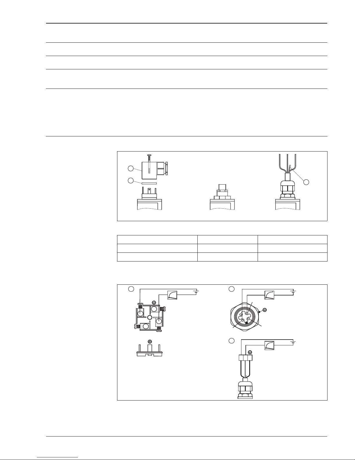
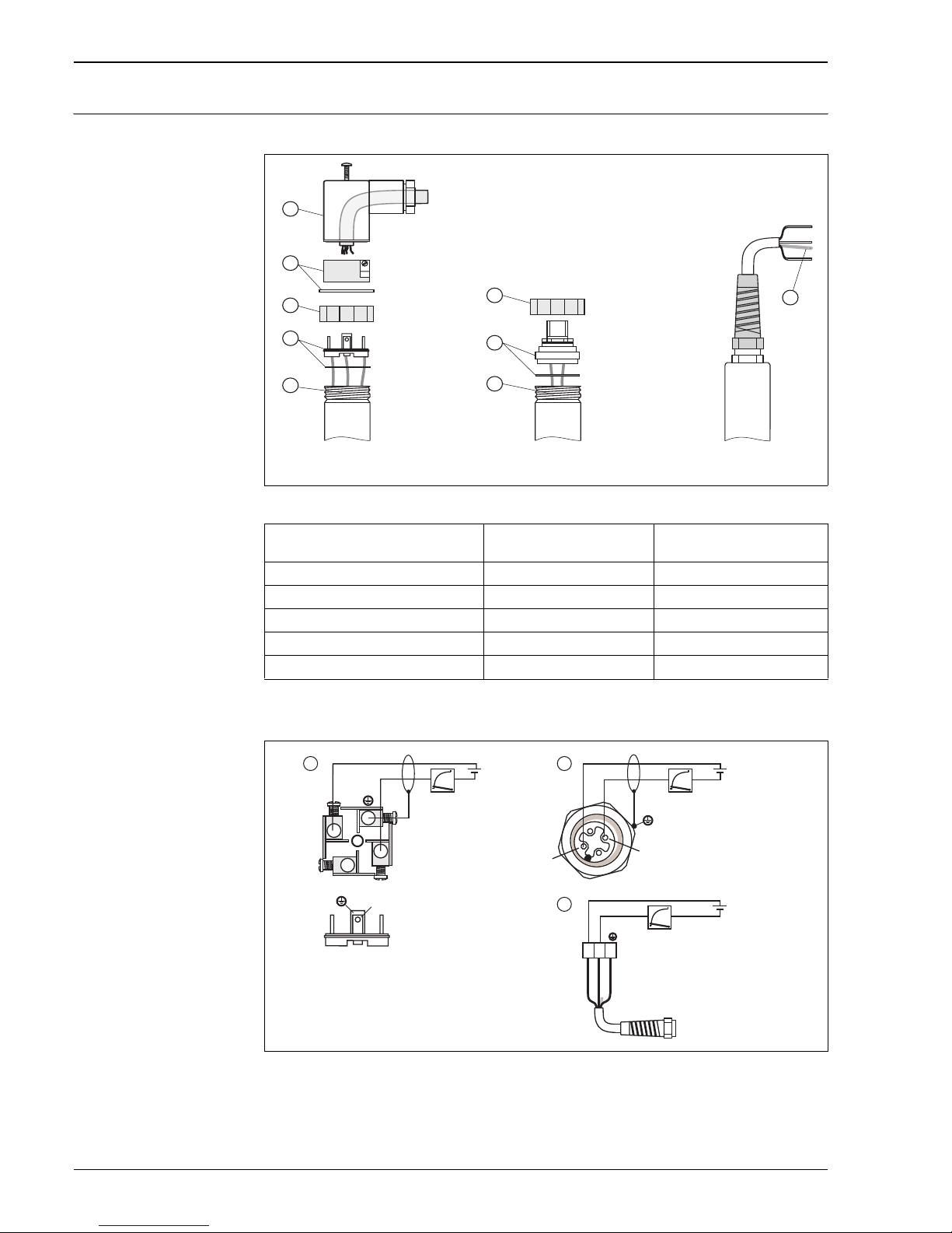
PMC131 Plug/cable connection
P01-PMC131xx-04-xx-xx-xx-001
Electrical connection: Analog/current output
P01-PMC131xx-04-xx-xx-xx-002
1 Plug M 16 x 1.5 (DIN 43650/A), ½ NPT
2 Plug M 12 x 1
3 Cable (rd = red, bk = black, gnye = green-yellow)
Plug M 16 x 1.5 (DIN 43650/A), ½ NPT Plug M 12x1 5 m/25 m cable
➀ Plug-in housing ➀ Reference pressure line
➁ Gasket
M16 / ½ NPT
M12x1
5 m/25 m
1
2
ENDRESS+HAUSER
CERABAR T
ENDRESS+HAUSER
CERABAR T
ENDRESS+HAUSER
CERABAR T
1
–
–
–
+
+
+
+
PE
–
rd
bk
gnye
2
1
1+
2–
12...30 V
12...30 V
12...30 V
4...20 mA
4...20 mA
4...20 mA
1
2
3
1+
2
3-
Cerabar T
6 Endress+Hauser
PMP131 and PMP135 Plug/cable connection
P01-PMP13xxx-04-xx-xx-xx-001
Electrical connection: Analog/current output
P01-PMP13xxx-04-xx-xx-xx-002
1 Plug M 16 x 1.5 (DIN 43650/A), ½ NPT and plug DIN 43650/C
2 Plug M 12 x 1
3 Cable (rd = red, wh = white, gn = green)
For electrical connection provided by customer use only shielded cable
Plug M 16 x 1.5 (DIN 43650/A), ½ NPT
Plug DIN 43650/C
Plug M 12x1 5 m cable, only analog output
➀ Plug-in housing ➀ Coupling nut ➀ Reference pressure line
➁ Plug-in jack with gasket ➁ Connector with gasket
➂ Coupling nut ➂ Operating potentiometer (inner)
➃ Plug with O-ring
➄ Operating potentiometer (inner)
DIN 43 650/A (M16 / ½ NPT)
DIN 43650/C
M12x1
5 m
1
1
1
2
2
3
3
4
5
–
–
–
+
+
+
+
PE
–
rd
wh
gn
3
3
2
1
1+
2–
12...30 V
12...30 V
12...30 V
4...20 mA
4...20 mA
4...20 mA
1
2
3
1+
3-

Cerabar T
Endress+Hauser 7
Electrical connection (switch output)
P01-PMP13xxx-04-xx-xx-xx-003
1 Plug M 16 x 1.5 (DIN 43650/A), ½ NPT
2 Plug M 12 x 1
R External load, e.g. relay, programmable logic controller, distributed control system
For electrical connection provided by customer use only shielded cable
PMP131 Electrical connection: Analog-/voltage output
P01-PMP131xx-04-xx-xx-xx-001
1 Plug M 16 x 1,5 (DIN 43650/A), ½ NPT and plug DIN 43 650/C
2 Plug M 12 x 1
3 Cable (rd = red, wh = white, gn = green)
For electrical connection provided by customer use only shielded cable
Supply voltage PMC131
11 to 30 V DC
PMP131 and PMP135 (current output, 2-wire version)
• For non-hazardous areas: 12 to 30 V DC
• Ex i: no-load voltage ≤ 26 V DC, short-circuit current ≤ 100 mA, power consumption ≤ 0.8 W
PMP131 (voltage output, 3-wire version)
• 15...30 V DC
PMP131 and PMP135 (switch output)
• 18 to 32 V DC, current consumption without load < 20 mA, with reverse polarity protection
Residual ripple • Analog output: max. 5 % of supply voltage
• Switch output: max. 10 % of supply voltage
Cable entry → See Page 18, "Ordering information" section.
––
++
2–1+
3+
R
R
18...32 V18...32 V
3
2
1
1
2
1+
2-
3
–
–
–
+
+
+
+
+
PE
–
rd
bk
wh
gn
3+
3-
2-
1+
1+
2+
15...30 V
15...30 V
15...30 V
0...10 V
0...10 V
0...10 V
1
2
3
Cerabar T
8 Endress+Hauser
Performance characteristics
Reference operating
conditions
as per DIN IEC 60770, TU = 25 °C
Long-term stability ≤ 0.15 % of URL per year
Maximum measured error
of analog output
(under reference operating
conditions)
The measured error comprises the non-linearity including hysteresis and non-reproducibility in accordance
with the limit point method as per IEC 60770.
PMC131
• ≤ 0.5 % of (URL - LRL) x TD
1)
PMP131 and PMP135
• ≤ 0.5 % of URL
Switch point PMP131 and PMP135
• Deviation: ≤ 1 % of URL
• Non-reproducibility: ≤ 0.5 % of URL
Rise time (T90) PMC131
20 ms
Settling time PMP131 and PMP135
2 to 5 ms
1) extended specifications apply to customer-specific measuring ranges
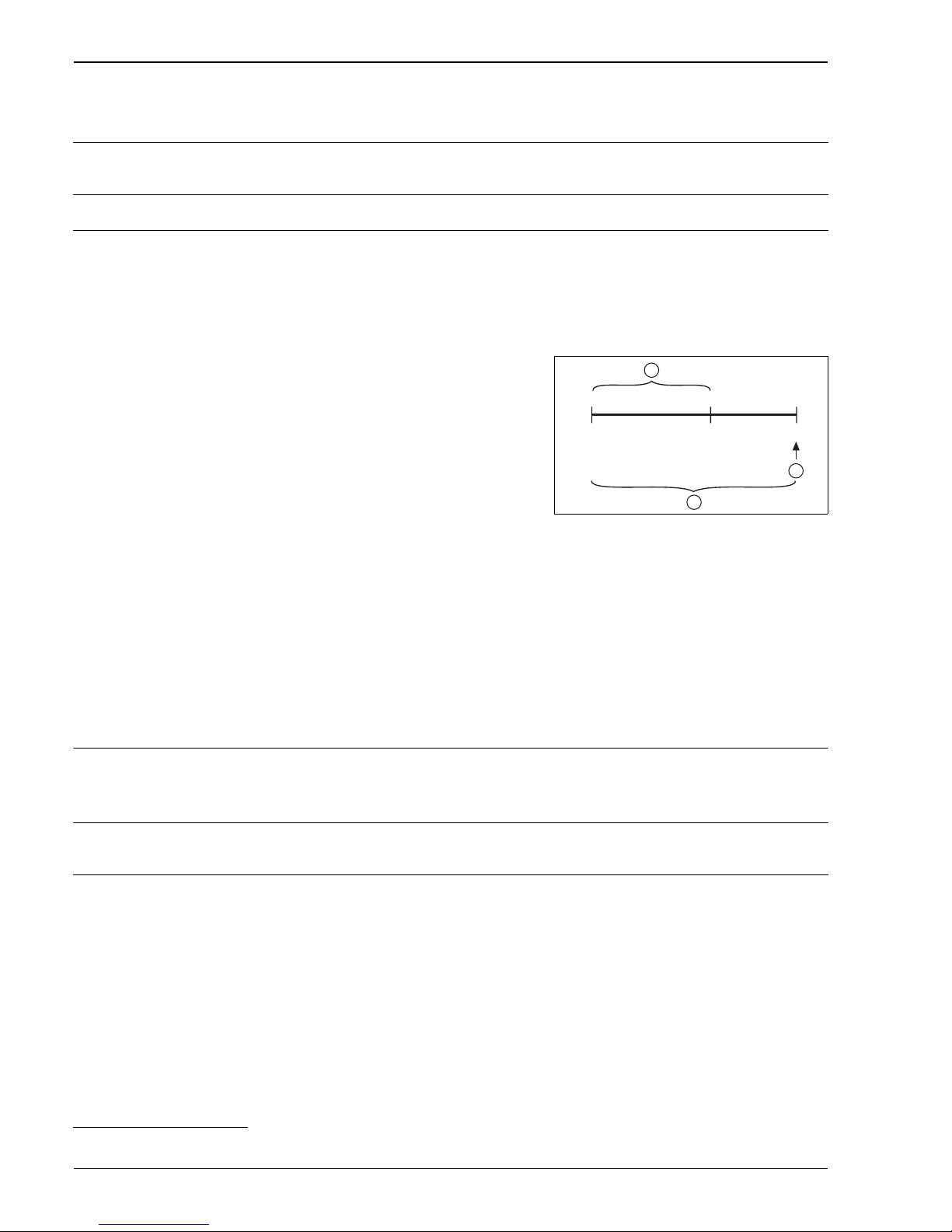
Example: PMC131 version "A1R"
• Nominal value = 10 bar
• Upper range value (URV) = 6 bar
• Lower range value (LRV) = 0 bar
Turn down (is set at factory):
• Nominal value / (URV – LRV)⏐= 10 bar/6 bar = 10:6
P01-PMx13xxx-05-xx-xx-xx-001
Example: PMC131 version "A1R"
set span: 0 to 6 bar; nominal value = 10 bar
1 Span set and calibrated at the factory (measuring
range)
2 Nominal value i Upper Range Limit (URL)
3 Sensor measuring range
LRL Lower Range Limit
URL Upper Range Limit
LRV Lower Range Value
URV Upper Range Value
0 bar +10 bar
URLURV
LRL = LRV
+6 bar
2
1
3
 Loading...