

Endress+Hauser Deltapilot S FMB70, Cerabar S PMC71, Cerabar S PMP71, Cerabar S PMP75 Operating Instructions Manual
Operating Instructions
Deltapilot S FMB70
Hydrostatic Level Measurement
BA00372P/00/EN/17.14
71270399
Valid from software version:
04.00.zz
Deltapilot S FMB70 with FOUNDATION Fieldbus
TAG No.: XXX000
Ser. No.: X000X000000
Order code 00X00-XXXX0XX0XXX
www.endress.com/deviceviewer Endress+Hauser Operations App
Serial number
A0023555
2 Endress+Hauser

Deltapilot S FMB70 with FOUNDATION Fieldbus Table of contents
Table of contents
1 Safety instructions . . . . . . . . . . . . . . . . 4
1.1 Designated use . . . . . . . . . . . . . . . . . . . . . . . . . . . . 4
1.2 Installation, commissioning and operation . . . . . . . . 4
1.3 Operational safety and process safety . . . . . . . . . . . . 4
1.4 Notes on safety conventions and icons . . . . . . . . . . . 5
2 Identification . . . . . . . . . . . . . . . . . . . . 6
2.1 Product identification . . . . . . . . . . . . . . . . . . . . . . . 6
2.2 Device designation . . . . . . . . . . . . . . . . . . . . . . . . . 6
2.3 Scope of delivery . . . . . . . . . . . . . . . . . . . . . . . . . . . 8
2.4 CE mark, Declaration of Conformity . . . . . . . . . . . . 8
2.5 Registered trademarks . . . . . . . . . . . . . . . . . . . . . . . 8
3 Installation . . . . . . . . . . . . . . . . . . . . . . 9
3.1 Incoming acceptance and storage . . . . . . . . . . . . . . . 9
3.2 Installation conditions . . . . . . . . . . . . . . . . . . . . . . . 9
3.3 Installation instructions . . . . . . . . . . . . . . . . . . . . . . 9
3.4 Post-installation check . . . . . . . . . . . . . . . . . . . . . . 15
4 Wiring . . . . . . . . . . . . . . . . . . . . . . . . 16
4.1 Connecting the device . . . . . . . . . . . . . . . . . . . . . . 16
4.2 Connecting the measuring unit . . . . . . . . . . . . . . . 17
4.3 Overvoltage protection (optional) . . . . . . . . . . . . . . 18
4.4 Post-connection check . . . . . . . . . . . . . . . . . . . . . . 18
8 Diagnostics and troubleshooting . . . . . 69
8.1 Troubleshooting . . . . . . . . . . . . . . . . . . . . . . . . . . . 69
8.2 Diagnostic information on local display . . . . . . . . . . 70
8.3 Diagnostic event in the operating tool . . . . . . . . . . 71
8.4 Diagnostic messages in the DIAGNOSTIC Transducer
Block (TRDDIAG) . . . . . . . . . . . . . . . . . . . . . . . . . 72
8.5 Overview of diagnostic events . . . . . . . . . . . . . . . . 75
8.6 Response of outputs to errors . . . . . . . . . . . . . . . . . 84
8.7 Confirming messages . . . . . . . . . . . . . . . . . . . . . . . 85
8.8 Repair . . . . . . . . . . . . . . . . . . . . . . . . . . . . . . . . . . 85
8.9 Repair of Ex-certified devices . . . . . . . . . . . . . . . . . 85
8.10 Spare Parts . . . . . . . . . . . . . . . . . . . . . . . . . . . . . . 86
8.11 Return . . . . . . . . . . . . . . . . . . . . . . . . . . . . . . . . . . 86
8.12 Disposal . . . . . . . . . . . . . . . . . . . . . . . . . . . . . . . . . 86
8.13 Software history . . . . . . . . . . . . . . . . . . . . . . . . . . . 86
9 Technical data . . . . . . . . . . . . . . . . . . . 87
Index . . . . . . . . . . . . . . . . . . . . . . . . . . . . . . 88
5 Operation . . . . . . . . . . . . . . . . . . . . . . 19
5.1 Onsite display (optional) . . . . . . . . . . . . . . . . . . . . 19
5.2 Operating elements . . . . . . . . . . . . . . . . . . . . . . . . 21
5.3 FOUNDATION Fieldbus interface . . . . . . . . . . . . . 24
5.4 Local operation – onsite display connected . . . . . . . 36
5.5 FieldCare . . . . . . . . . . . . . . . . . . . . . . . . . . . . . . . 39
5.6 HistoROM®/M-DAT (optional) . . . . . . . . . . . . . . 39
5.7 Locking/unlocking operation . . . . . . . . . . . . . . . . . 41
5.8 Simulation . . . . . . . . . . . . . . . . . . . . . . . . . . . . . . . 42
5.9 Factory setting (reset) . . . . . . . . . . . . . . . . . . . . . . 43
6 Commissioning. . . . . . . . . . . . . . . . . . 45
6.1 Function check . . . . . . . . . . . . . . . . . . . . . . . . . . . 45
6.2 Commissioning via an FF configuration program . . 45
6.3 Selecting the language and measuring mode . . . . . 47
6.4 Position adjustment . . . . . . . . . . . . . . . . . . . . . . . . 48
6.5 Level measurement . . . . . . . . . . . . . . . . . . . . . . . . 50
6.6 Pressure measurement . . . . . . . . . . . . . . . . . . . . . . 55
6.7 Scaling the OUT parameter . . . . . . . . . . . . . . . . . . 57
6.8 Configuring event behavior in accordance with
FOUNDATION Fieldbus Specification FF912 Field
Diagnostic Profile . . . . . . . . . . . . . . . . . . . . . . . . . 58
7 Maintenance. . . . . . . . . . . . . . . . . . . . 68
7.1 Exterior cleaning . . . . . . . . . . . . . . . . . . . . . . . . . . 68
Endress+Hauser 3

Safety instructions Deltapilot S FMB70 with FOUNDATION Fieldbus
1 Safety instructions
1.1 Designated use
The Deltapilot S is a hydrostatic pressure sensor for measuring pressure and level.
The manufacturer accepts no liability for damages resulting from incorrect use or use other than that designated.
1.2 Installation, commissioning and operation
The device is designed to meet state-of-the-art safety requirements and complies with applicable
standards and EC regulations. If installed incorrectly or used for applications for which it is not
intended, however, it is possible that application-related dangers may arise, e.g. product overflow
due to incorrect installation or configuration. For this reason, installation, connection to the
electricity supply, commissioning, operation and maintenance of the measuring system must only
be carried out by trained, qualified specialists authorized to perform such work by the facility's
owner-operator. The specialist staff must have read and understood these Operating Instructions
and must follow the instructions they contain. Modifications and repairs to the device are
permissible only if they are expressly approved in the Operating Instructions. Pay particular
attention to the technical data on the nameplate.
1.3 Operational safety and process safety
Alternative monitoring measures must be taken to ensure operational safety and process safety during configuration, testing and maintenance work on the device.
1.3.1 Hazardous areas (optional)
Devices for use in hazardous areas are fitted with an additional nameplate ( ä 6). If using the measuring system in hazardous areas, the appropriate national standards and regulations must be observed. The device is accompanied by separate "Ex documentation", which is an integral part of these Operating Instructions. The installation regulations, connection values and safety instructions listed in this Ex document must be observed. The documentation number of the related safety instructions is also indicated on the additional nameplate.
• Ensure that all personnel are suitably qualified.
• Measuring point requirements with regard to measurement and safety must be observed.
4 Endress+Hauser
Deltapilot S FMB70 with FOUNDATION Fieldbus Safety instructions
t >85°C
1.4 Notes on safety conventions and icons
In order to highlight safety-relevant or alternative operating procedures in the manual, the following conventions have been used, each indicated by a corresponding icon in the margin.
Symbol Meaning
Warning!
#
"
!
0
-
.
%
&
)
*
+
A warning highlights actions or procedures which, if not performed correctly, will lead to personal injury, a safety hazard or destruction of the instrument.
Caution!
Caution highlights actions or procedures which, if not performed correctly, may lead to personal injury or incorrect functioning of the instrument.
Note!
A note highlights actions or procedures which, if not performed correctly, may indirectly affect operation or may lead to an instrument response which is not planned.
Device certified for use in explosion hazardous area
If the device has this symbol embossed on its nameplate, it can be installed in an explosion hazardous area or a non-explosion hazardous area, according to the approval.
Explosion hazardous area
Symbol used in drawings to indicate explosion hazardous areas.
– Devices used in hazardous areas must possess an appropriate type of protection.
Safe area (non-explosion hazardous area)
Symbol used in drawings to indicate, if necessary, non-explosion hazardous areas.
– Devices used in hazardous areas must possess an appropriate type of protection. Lines used in
hazardous areas must meet the necessary safety-related characteristic quantities.
Direct voltage
A terminal to which or from which a direct current or voltage may be applied or supplied.
Alternating voltage
A terminal to which or from which an alternating (sine-wave) current or voltage may be applied or supplied.
Grounded terminal
A grounded terminal, which as far as the operator is concerned, is already grounded by means of an earth grounding system.
Protective grounding (earth) terminal
A terminal which must be connected to earth ground prior to making any other connection to the equipment.
Equipotential connection (earth bonding)
A connection made to the plant grounding system which may be of type e.g. neutral star or equipotential line according to national or company practice.
Temperature resistance of the connection cables
States, that the connection cables must be resistant to a temperature of at least 85 °C (185 °F).
Safety instruction
For safety instructions refer to the manual for the appropriate instrument version.
Endress+Hauser 5
Identification Deltapilot S FMB70 with FOUNDATION Fieldbus
Ser. no.:
Order code:
Ext. order code:
2
5
6
3
4
1
2 Identification
2.1 Product identification
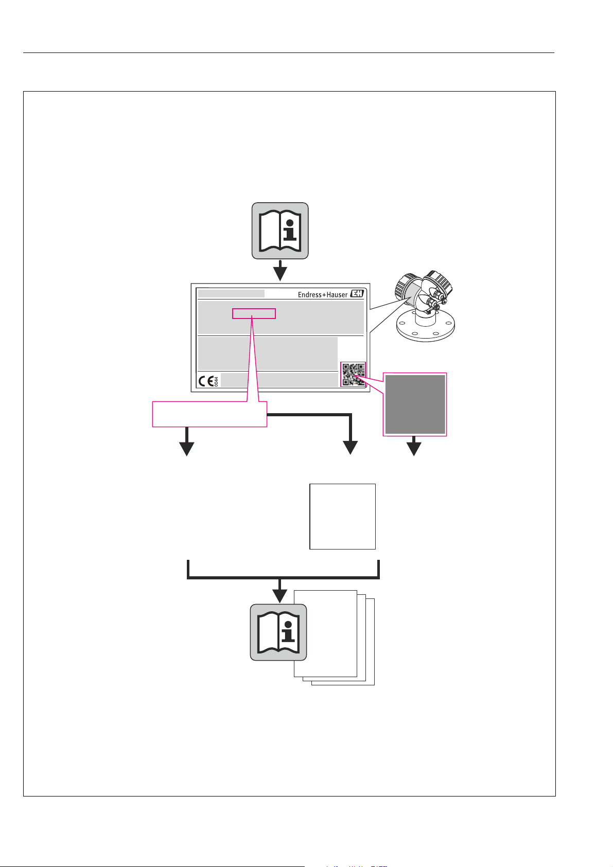
The following options are available for identification of the measuring device:
• Nameplate specifications
• Order code with breakdown of the device features on the delivery note
• Enter serial numbers from nameplates in W@M Device Viewer (www.endress.com/deviceviewer): All information about the measuring device is displayed.
For an overview of the technical documentation provided, enter the serial number from the nameplates in the W@M Device Viewer (www.endress.com/deviceviewer).
2.2 Device designation
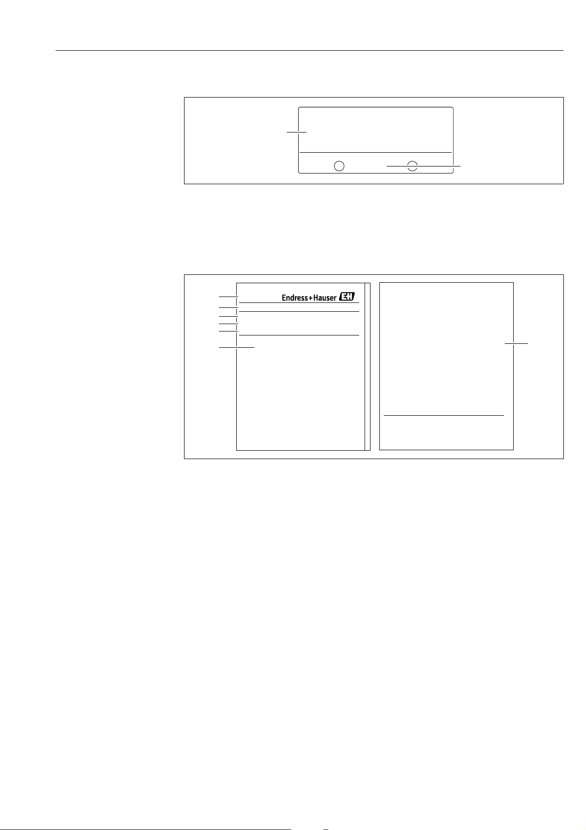
2.2.1 Nameplates
!
Note!
• The MWP (maximum working pressure) is specified on the nameplate. This value refers to a reference temperature of 20°C (68°F) or 100°F (38 °C) for ASME flanges.
• The pressure values permitted at higher temperatures can be found in the following standards:
– EN 1092-1: 2001 Tab. 18
1)
– ASME B 16.5a – 1998 Tab. 2-2.2 F316
– ASME B 16.5a – 1998 Tab. 2.3.8 N10276
– JIS B 2220
• The test pressure corresponds to the overpressure limit (OPL) of the device = MWP x 1.5.
• The Pressure Equipment Directive (EC Directive 97/23/EC) uses the abbreviation "PS". The abbreviation "PS" corresponds to the MWP (maximum working pressure) of the measuring device.
1) With regard to their stability-temperature property, the materials 1.4435 and 1.4404 are grouped together under 13EO
in EN 1092-1 Tab. 18. The chemical composition of the two materials can be identical.
Aluminum housing (T14/T15)
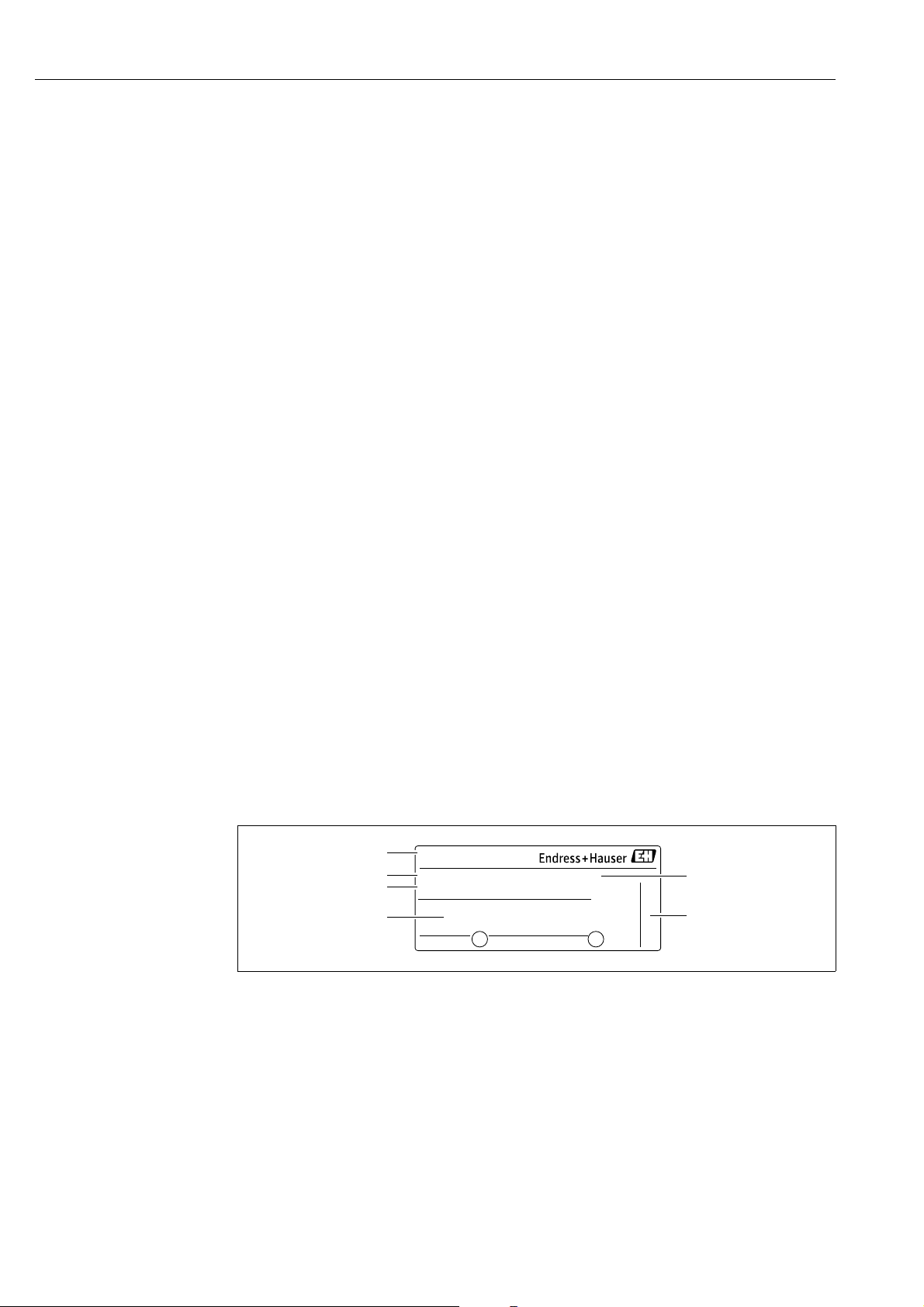
Fig. 1: Nameplate
1 Device name 2 Order code (for re-orders) 3 Extended order code (complete) 4 Technical data 5 Serial number (for identification) 6 Address of manufacturer
6 Endress+Hauser
A0016056
Deltapilot S FMB70 with FOUNDATION Fieldbus Identification
2
1
2
7
3
4
5
6
1
Ser. no.:
Order code:
Ext. ord. cd.:
Devices for use in hazardous areas are fitted with an additional nameplate.
A0021222
Fig. 2: Additional nameplate
1 Approval-specific information 2 Document number for safety instructions or drawing number
Hygenic stainless steel housing (T17)
A0021552
Fig. 3: Nameplate
1 Device name 2 Address of manufacturer 3 Order code (for re-orders) 4 Extended order code (complete) 5 Serial number (for identification) 6 Technical data 7 Approval-specific information and document number for safety instructions or drawing number
2.2.2 Identifying the sensor type
See parameter "Sensor Meas.Type" in Operating Instruction BA00303P.
Endress+Hauser 7

Identification Deltapilot S FMB70 with FOUNDATION Fieldbus
2.3 Scope of delivery
The scope of delivery comprises:
• Hydrostatic pressure sensor Deltapilot S
• For devices with the "HistoROM/M-DAT" option:
CD-ROM with Endress+Hauser operating program
• Optional accessories
Documentation supplied:
• The Operating Instructions BA00372P and BA00303P are available via the Internet.
See: www.endress.com Download.
• Brief Operating Instructions KA01026P
• Fold-out brochure KA00252P
• Final inspection report
• Additional safety instructions for Ex devices
• Optional: factory calibration form, test certificates
2.4 CE mark, Declaration of Conformity
The devices are designed to meet state-of-the-art safety requirements, have been tested and left the
factory in a condition in which they are safe to operate. The devices comply with the applicable
standards and regulations as listed in the EC Declaration of Conformity and thus comply with the
statutory requirements of the EC Directives. Endress+Hauser confirms the conformity of the device
by affixing to it the CE mark.
2.5 Registered trademarks
KALREZ, VITON, TEFLON
Registered trademarks of E.I. Du Pont de Nemours & Co., Wilmington, USA
TRI-CLAMP
Registered trademark of Ladish & Co., Inc., Kenosha, USA
TM
FOUNDATION
Registered trademark of the Fieldbus Foundation Austin, Texas, USA
GORE-TEX
Registered trademark of W.L. Gore & Associates, Inc., USA
Fieldbus
®
8 Endress+Hauser

Deltapilot S FMB70 with FOUNDATION Fieldbus Installation
3 Installation
3.1 Incoming acceptance and storage
3.1.1 Incoming acceptance
• Check the packaging and the contents for damage.
• Check the shipment, make sure nothing is missing and that the scope of supply matches your order.
3.1.2 Transport
Caution!
"
Follow the safety instructions and transport conditions for devices of more than 18 kg (39.69 lbs).
Transport the measuring device to the measuring point in its original packaging or at the process
connection.
3.1.3 Storage
!
The device must be stored in a dry, clean area and protected against impact (EN 837-2).
Storage temperature range:
• –40 to +90 °C (–40 to +194°F)
• Onsite display: –40 to +85°C (–40 to +185°F)
• Separate housing: –40 to +60°C (–40 to +140°F)
3.2 Installation conditions
3.2.1 Dimensions
For dimensions, please refer to the Technical Information for Deltapilot S TI00416P,
"Mechanical construction" section.
3.3 Installation instructions
Note!
• Due to the orientation of the Deltapilot S, there may be a shift in the zero point, i.e. when the
container is empty or partially full, the measured value does not display zero. You can correct this
zero point shift using the "Zero" key on the electronic insert or externally on the device or via the
onsite display. See ä 21, Section 5.2.1 "Position of the operating elements", ä 22,
Section 5.2.2 "Function of the operating elements – onsite display not connected" and ä 48,
Section 6.4 "Position adjustment".
• To ensure optimal readability of the onsite display, it is possible to rotate the housing up to 380°. See ä 14, Section 3.3.5 "Rotating the housing".
• Endress+Hauser offers a mounting bracket for installations on pipes or walls. See ä 12, Section 3.3.3 "Wall and pipe-mounting (optional)".
Endress+Hauser 9
Installation Deltapilot S FMB70 with FOUNDATION Fieldbus
1
1
1
FIELDTERMINALS
FIELDTERMINALS
FIELDTERMINALSFIELDTERMINALS
FIELDTERMINALS
FIELDTERMINALS
FIELD
TERMINALS
FIELDTERMINALS
FIELD
TERMINALS
FIELDTERMINALS
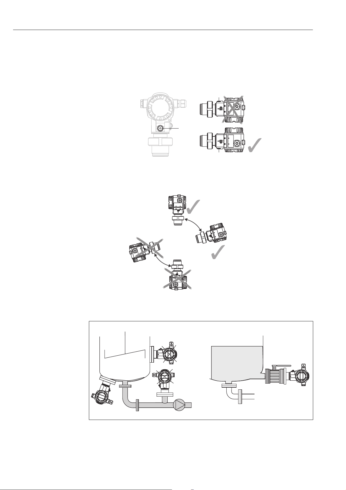
3.3.1 Installation instructions
!
Note!
• If a heated Deltapilot S is cooled during the cleaning process (e.g. by cold water), a vacuum
develops for a short time, whereby moisture can penetrate the sensor through the pressure
compensation (1). If this is the case, mount the Deltapilot S with the pressure compensation (1)
pointing downwards.
®
• Keep the pressure compensation and GORE-TEX
filter (1) free from contamination.
• Do not clean or touch the process isolating diaphragm with hard or pointed objects.
• The device must be installed as follows in order to comply with the cleanability requirements of
the ASME-BPE (Part SD Cleanability):
Level measurement
P01-PMP75xxx-11-xx-xx-xx-000
Fig. 4: Measuring arrangement for level
• Always install the device below the lowest measuring point.
10 Endress+Hauser
Deltapilot S FMB70 with FOUNDATION Fieldbus Installation
➁➀
• Do not install the device at the following positions:
– in the filling curtain
– in the tank outflow
– in the suction area of a pump
– or at a point in the tank that can be affected by pressure pulses from the agitator
• The calibration and functional test can be carried out more easily if you mount the device downstream of a shutoff device.
• Deltapilot S must be included in the insulation for media that can harden when cold.
Pressure measurement in gases
• Mount Deltapilot S with shutoff device above the tapping point so that any condensate can flow into the process.
Pressure measurement in steams
• Mount Deltapilot S with siphon above the tapping point.
• Fill the siphon with liquid before commissioning.
The siphon reduces the temperature to almost the ambient temperature.
Pressure measurement in liquids
• Mount Deltapilot S with the shutoff device below or at the same level as the tapping point.
#
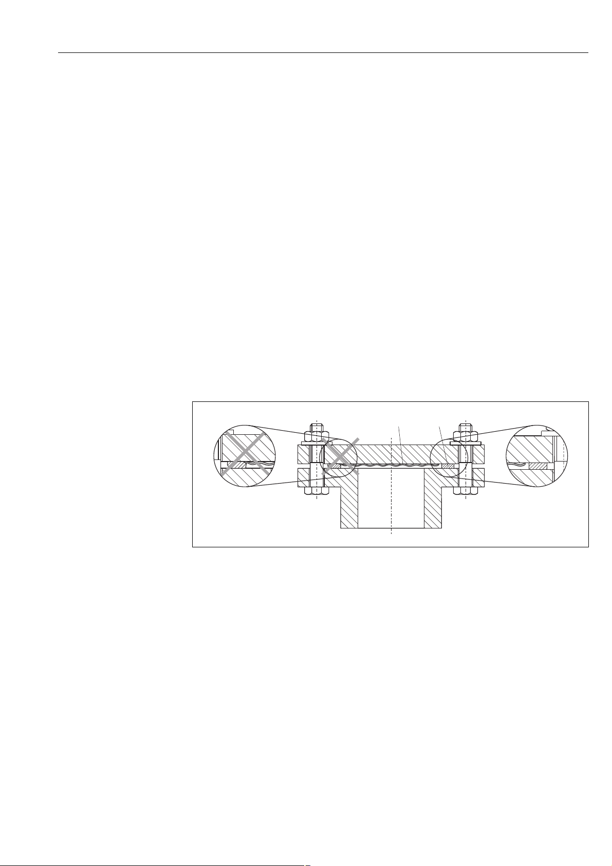
3.3.2 Seal for flange mounting
P01-FMD7xxxx-11-xx-xx-xx-002
Fig. 5: Mounting the versions with flange or diaphragm seal
1 Process isolating diaphragm
2Seal
Warning!
The seal is not allowed to press on the process isolating diaphragm as this could affect the
measurement result.
Endress+Hauser 11
Installation Deltapilot S FMB70 with FOUNDATION Fieldbus
52 (2.05)
140 (5.51)
122 (4.8)
70 (2.76)
6 (0.24)
mm (in)
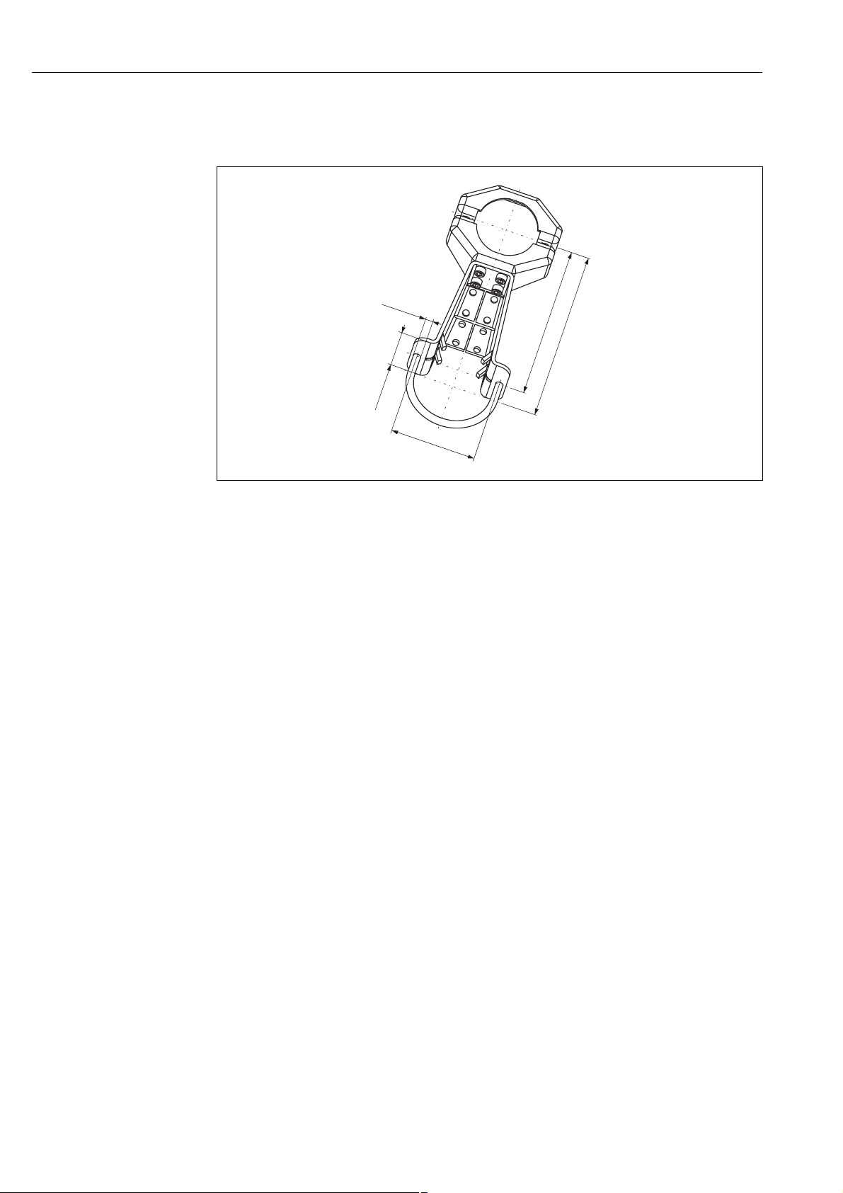
3.3.3 Wall and pipe-mounting (optional)
Endress+Hauser offers a mounting bracket for installations on pipes or walls.
P01-xMx5xxxx-06-xx-xx-xx-001
Please note the following when mounting:
• When mounting on a pipe, tighten the nuts on the bracket uniformly with a torque of at least 5 Nm (3.69 lbs ft).
12 Endress+Hauser
Deltapilot S FMB70 with FOUNDATION Fieldbus Installation
r ³ 120 mm
1
2
3
5
6
8
7
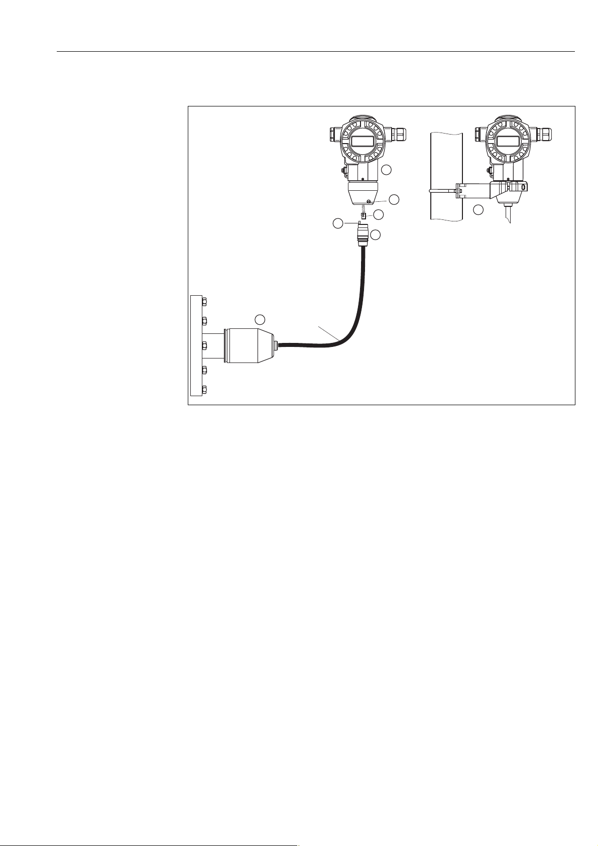
3.3.4 Assembling and mounting the "separate housing" version
P01-FMB70xxx-11-xx-xx-xx-003
Fig. 6: "Separate housing" version
1 In the "separate housing" version, the sensor is supplied with the process connection and cable ready-fitted.
2 Cable with connection jack
3 Pressure compensation
5 Connector
6Locking screw
7 Housing fitted with housing adapter, included
8 Mounting bracket suitable for wall and pipe mounting, included
Assembly and mounting
1. Plug the connector (item 5) into the corresponding connection jack of the cable (item 2).
2. Plug the cable into the housing adapter (item 7).
3. Tighten the locking screw (item 6).
4. Mount the housing on a wall or pipe using the mounting bracket (item 8).
When mounting on a pipe, tighten the nuts on the bracket uniformly with a torque of at least
5 Nm (3.69 lbs ft).
Mount the cable with a bending radius (r) 120 mm (4.72 in).
Endress+Hauser 13

Installation Deltapilot S FMB70 with FOUNDATION Fieldbus
max. 380°
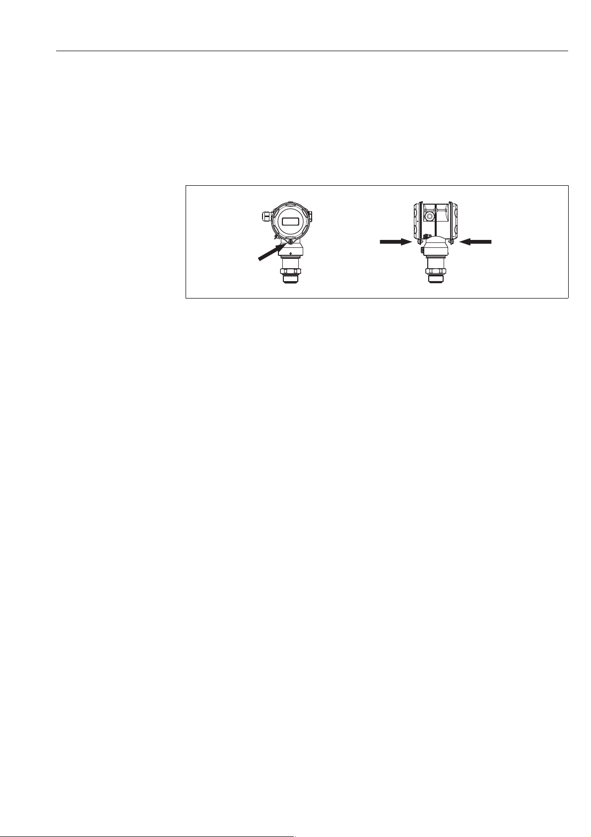
3.3.5 Rotating the housing
The housing can be rotated up to 380° by loosening the setscrew.
P01-FMB70xxx-17-xx-xx-xx-000
Fig. 7: Aligning the housing
– For aluminum housings (T14/T15): Loosen setscrew with a 2 mm (0.08 in) Allen key.
For hygienic stainless steel housings (T17): Loosen setscrew with a 3 mm (0.12 in) Allen key.
– Rotate housing (max. up to 380°).
– Retighten setscrew with 1 Nm (0.74 lbf ft).
3.3.6 Supplementary installation instructions
Seal
• Deltapilot M with a G 1 1/2 thread:
When screwing the device into the tank, the flat seal has to be positioned on the sealing surface
of the process connection. To avoid additional strain on the process isolating diaphragm, the
thread should never be sealed with hemp or similar materials.
• Deltapilot M with NPT threads:
– Wrap Teflon tape around the thread to seal it.
– Tighten the device at the hexagonal bolt only. Do not turn at the housing.
– Do not overtighten the thread when screwing. Max. torque: 20 to 30 Nm (14.75 to 22.13 lbf ft)
Sealing the probe housing
• Moisture must not penetrate the housing when mounting the device, establishing the electrical
connection and during operation.
• Always firmly tighten the housing cover and the cable entries.
3.3.7 Mounting of the profile seal for universal process mounting
adapter
For details on mounting, see KA00096F/00/A3.
14 Endress+Hauser
Deltapilot S FMB70 with FOUNDATION Fieldbus Installation
3.3.8 Closing the housing cover
!
Note!
When closing the housing cover, make sure that the threads of the cover and the housing are free
from dirt, such as sand. If you encounter resistance when closing the cover, check the threads again
for fouling and dirt.
Closing the covers on the hygienic stainless steel housing (T17)
P01-FMB70xxx-17-xx-xx-xx-001
Fig. 8: Closing the covers
The covers for the terminal and electronics compartment are hooked into the housing and closed with a screw. These screws should be tightened handtight (2 Nm (1.48 lbf ft)) to the stop to ensure that the covers sit tightly.
3.4 Post-installation check
After installing the device, carry out the following checks:
• Are all screws firmly tightened?
• Are the housing covers screwed down tight?
Endress+Hauser 15
Wiring Deltapilot S FMB70 with FOUNDATION Fieldbus
➀
➁
➂
➃
➄
FF FF
FF FF
4 Wiring
4.1 Connecting the device
#
#
Warning!
If the operating voltage is > 35 VDC: Dangerous contact voltage at terminals.
Risk of electric shock!
In a wet environment, do not open the cover if voltage is present.
Warning!
Limitation of electrical safety due to incorrect connection!
• Risk of electric shock and/or explosion in hazardous areas! In a wet environment, do not open
the cover if voltage is present.
• When using the measuring device in hazardous areas, installation must comply with the
corresponding national standards and regulations and the Safety Instructions or Installation or
Control Drawings.
• Devices with integrated overvoltage protection must be grounded.
• Protective circuits against reverse polarity, HF influences and overvoltage peaks are installed.
• The supply voltage must match the power supply on the nameplate. (See also ä 6,
Section 2.2.1 "Nameplates".)
• Switch off the supply voltage before connecting the device.
• Remove the housing cover of the terminal compartment.
• Guide the cable through the gland. For cable specifications, ä 17, Section 4.2.3.
• Connect the device in accordance with the following diagram.
• Screw down the housing cover.
• Switch on the supply voltage.
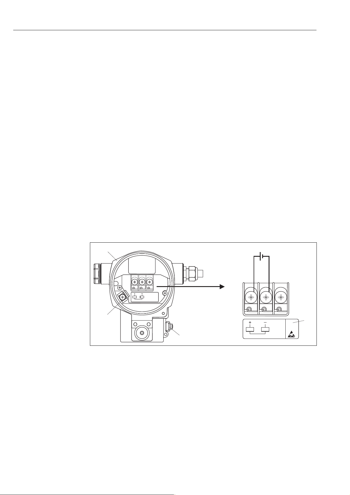
P01-xMx7xxxx-04-xx-xx-xx-009
Fig. 9: Electrical connection of FOUNDATION Fieldbus
Please refer also to Section 4.2.1 "Supply voltage", ä 17.
1 Housing 3 Internal ground terminal 3 External ground terminal 4 Supply voltage, for version in non-hazardous area = 9 to 32 V DC 5 Devices with integrated overvoltage protection are labeled OVP (overvoltage protection) here.
16 Endress+Hauser

Deltapilot S FMB70 with FOUNDATION Fieldbus Wiring
2
1
4
3
4.1.1 Devices with 7/8" plug
PIN assignment for 7/8" connector
PIN Meaning
1 Signal –
2 Signal +
3 Not assigned
4Shield
A0011176
4.2 Connecting the measuring unit
!
!
Note!
For further information on the network structure and grounding and for further bus system
components such as bus cables, see the relevant documentation, e.g. Operating Instructions
BA00013S "FOUNDATION Fieldbus Overview" and the FOUNDATION Fieldbus Guideline.
4.2.1 Supply voltage
• Version for non-hazardous area: 9 to 32 V DC
Note!
• When using the measuring device in hazardous areas, installation must comply with the corresponding national standards and regulations and the Safety Instructions or Installation or Control Drawings.
• All explosion-protection data are given in a separate documentation which is available upon request. The Ex documentation is available as standard with all devices approved for use in explosion hazardous areas.
4.2.2 Current consumption
15.5 mA ±1 mA, switch-on current corresponds to IEC 61158-2, Clause 21.
4.2.3 Cable specification
• Use a twisted, shielded two-wire cable, preferably cable type A.
• Terminals for wire cross-sections: 0.5 to 2.5 mm
• Outer cable diameter: 5 to 9 mm (0.2 to 0.35 in)
2
(20 to 14 AWG)
!
Note!
For further information on the cable specifications, see Operating Instructions BA00013S
"FOUNDATION Fieldbus Overview", FOUNDATION Fieldbus Guideline and IEC 61158-2 (MBP).
4.2.4 Grounding and shielding
Deltapilot S must be grounded, for example by means of the external ground terminal.
Different grounding and shielding installation methods are available for FOUNDATION Fieldbus networks such as:
• Isolated installation (see also IEC 61158-2)
• Installation with multiple grounding
• Capacitive installation
Endress+Hauser 17

Wiring Deltapilot S FMB70 with FOUNDATION Fieldbus
4.3 Overvoltage protection (optional)
Devices showing version "M" in feature 100 "Additional options 1" or feature 110 "Additional
options 2" in the order code are equipped with overvoltage protection (see also Technical
Information TI00416P "Ordering information").
• Overvoltage protection:
– Nominal functioning DC voltage: 600 V
– Nominal discharge current: 10 kA
• Surge current check î = 20 kA as per DIN EN 60079-14: 8/20 s satisfied
• Arrester AC current check I = 10 A satisfied
#
Warning!
Devices with integrated overvoltage protection must be grounded.
4.4 Post-connection check
Perform the following checks after completing electrical installation of the device:
• Does the supply voltage match the specifications on the nameplate?
• Is the device connected as per Section 4.1?
• Are all screws firmly tightened?
• Are the housing covers screwed down tight?
As soon as voltage is applied to the device, the green LED on the electronic insert lights up for a few seconds or the connected onsite display lights up.
18 Endress+Hauser

Deltapilot S FMB70 with FOUNDATION Fieldbus Operation
5Operation
Feature 20 "Output; operation" in the order code provides you with information on the operating options available to you.
Versions in the order code Operation
P FOUNDATION Fieldbus; external operation, LCD Via onsite display and 1 key on the exterior of the
device
Q FOUNDATION Fieldbus; internal operation, LCD Via onsite display and 1 key on the inside of the device
R FOUNDATION Fieldbus; internal operation Without onsite display, 1 key on the inside of the device
5.1 Onsite display (optional)
A 4-line liquid crystal display (LCD) is used for display and operation. The onsite display shows
measured values, fault messages and notice messages.
The display of the device can be turned in 90° steps.
Depending on the orientation of the device, this makes it easy to operate the device and read the
measured value.
Functions:
• 8-digit measured value display including sign and decimal point, unit display
• Bar graph as graphic display of the current pressure measured value in relation to the set pressure range in the Pressure Transducer Block. The pressure range is set by means of the SCALE_IN parameter.
• Easy and complete menu guidance by dividing the parameters into several levels and groups
• Menu guidance
The onsite display is available in English. Needless to say, the device can also be operated in 6
languages (de, en, fr, es, jp, ch) via the DTM or EDD. The FieldCare program is an E+H DTM
operating tool and can be acquired from endress.com.
• Each parameter has a 3-digit ID to aid navigation
• Option of configuring the display according to individual requirements and preferences, such as language, alternating display, contrast setting, display of other measured values such as sensor temperature
• Comprehensive diagnostic functions (fault and warning message, maximum indicator, etc.)
• Rapid and safe commissioning using Quick Setup menus
Endress+Hauser 19
Operation Deltapilot S FMB70 with FOUNDATION Fieldbus
E
+
–
Bargraph
Operating keys
Symbol
Bargraph
ValueFunction name
Unit
Header line
Information
line
Main line
Parameter
Identification
number
Editing modes
Selection
options
Value that
can be edited
Current measured value
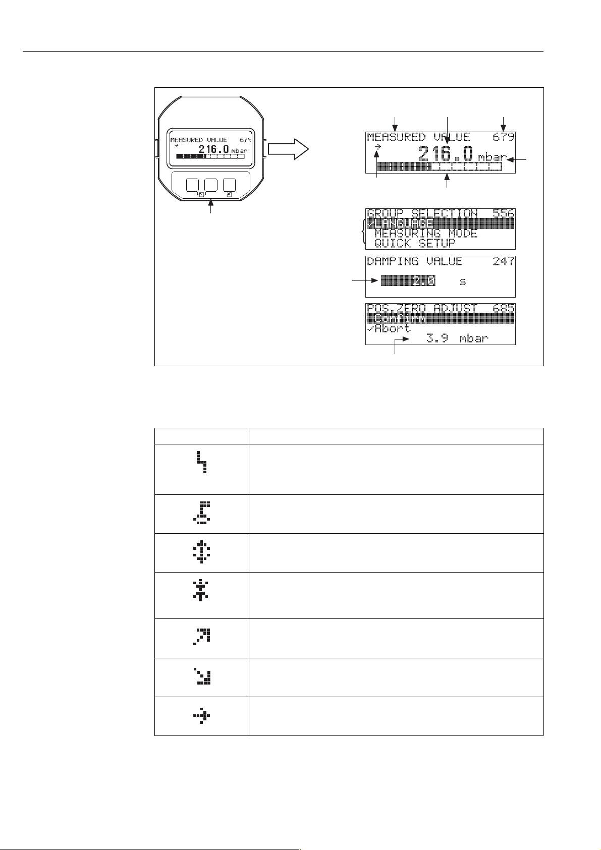
Measured value display
P01-xxxxxxxx-07-xx-xx-en-011
The following table illustrates the symbols that can appear on the onsite display. Four symbols can occur at one time.
Symbol Meaning
Alarm symbol
– Symbol flashing: warning, device continues measuring.
– Symbol permanently lit: error, device does not continue measuring.
Note: The alarm symbol may overlie the tendency symbol.
Lock symbol
The operation of the device is locked. Unlock device, ä 41, Section 5.7 "Locking/ unlocking operation".
Communication symbol
Data transfer via communication
Simulation symbol
Simulation mode is activated. DIP switch 2 for simulation is set to "On".
See also Section 5.2.1 "Position of the operating elements" and ä 42, Section 5.8
"Simulation"
Tendency symbol (increasing)
The primary value of the Pressure Transducer Block is increasing.
Tendency symbol (decreasing)
The primary value of the Pressure Transducer Block is decreasing.
Tendency symbol (constant)
The primary value of the Pressure Transducer Block has remained constant over the past few minutes.
20 Endress+Hauser
Deltapilot S FMB70 with FOUNDATION Fieldbus Operation
➀
0%
Zero
HW
21
PC
1
2
➀➁
➃
on
off
➂
➄
➅
Sim.
Sensor
on
off
Simulation
0%
Zero
Display
Histo
ROM
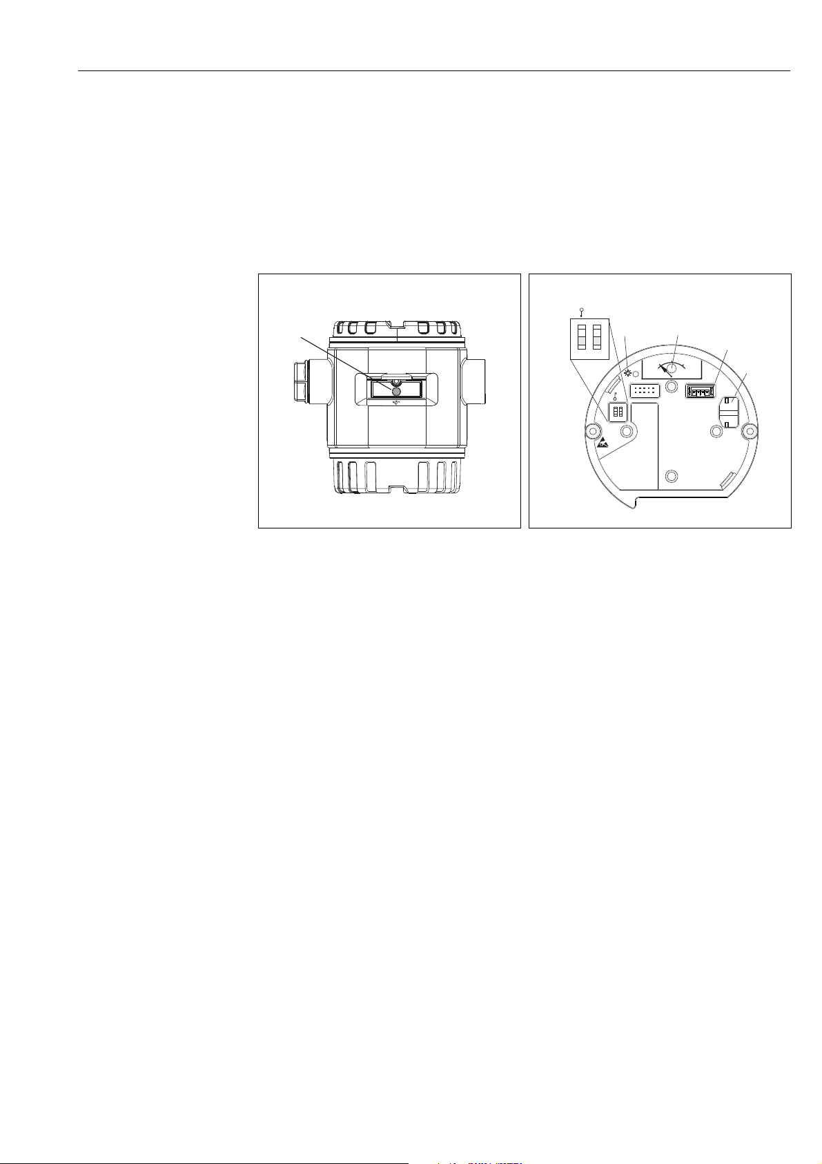
5.2 Operating elements
5.2.1 Position of the operating elements
On the aluminum housing (T14/T15), the operating key is located either under the protective flap
on the exterior of the device or inside on the electronic insert. In the case of the hygienic stainless
steel housing (T17), the operating key is always inside on the electronic insert. In addition, there
are three operating keys on the optional onsite display.
P01-PMx7xxxx-19-xx-xx-xx-075
Fig. 10: External operating key, under the protective flap
1 Operating key for position adjustment (zero point
correction) and total reset
P01-xxxxxxxx-19-xx-xx-xx-106
Fig. 11: Operating key and operating elements, internal
1 Green LED to indicate value is accepted
2 Operating key for position adjustment (zero point
correction) and total reset
3 Slot for optional display
4 Slot for optional HistoROM
®
/M-DAT
5 DIP switch for locking/unlocking parameters
relevant to the measured value
6 DIP switch for simulation mode
Endress+Hauser 21

Operation Deltapilot S FMB70 with FOUNDATION Fieldbus
0%
Zero
1
2
on
off
Sim.
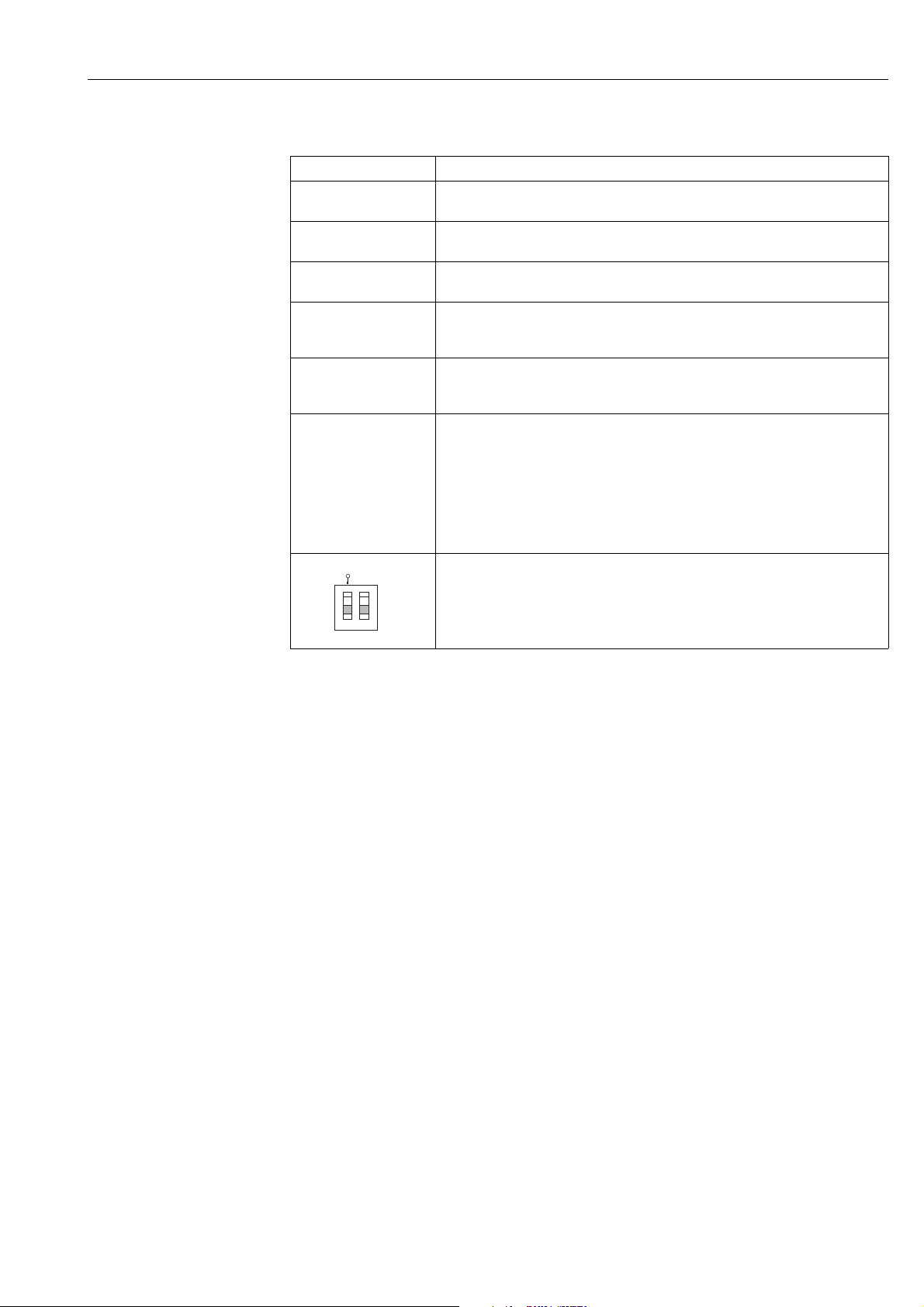
5.2.2 Function of the operating elements – onsite display not connected
Operating elements Meaning
– Position adjustment (zero point correction): press key for at least 3 seconds. The LED on
the electronic insert lights up briefly if the pressure applied has been accepted for
position adjustment.
See also the following section "Performing position adjustment on site".
– Total reset: press key for at least 12 seconds. The LED on the electronic insert lights up
briefly if a reset is being carried out.
– DIP switch 1: for locking/unlocking parameters relevant to the measured value.
Factory setting: off (unlocked)
See also ä 41, Section 5.7 "Locking/unlocking operation".
– DIP switch 2: for simulation mode
Factory setting: off (simulation mode off)
See also ä 42, Section 5.8 "Simulation"
!
P01-xxxxxxxx-19-xx-xx-xx-107
P01-xxxxxxxx-19-xx-xx-xx-134
Performing position adjustment on site
Note!
• Operation must be unlocked. See ä 41, Section 5.7 "Locking/unlocking operation".
• The device is configured for the MEASURING MODE level and LEVEL SELECTION level
easy pressure as standard.
– Operation via FF configuration program: In the Pressure Transducer Block, change the
measuring mode by means of the PRIMARY_VALUE_TYPE and LINEARIZATION parameters.
– Operation via digital communication: change the measuring mode by means of the
MEASURING MODE parameter.
– You can change the measuring mode by means of the MEASURING MODE parameter. See
ä 47, Section 6.3 "Selecting the language and measuring mode".
• The pressure applied must be within the nominal pressure limits of the sensor. See information
on the nameplate.
Perform position adjustment:
1. Pressure is present at device.
2. Press key for at least 3 seconds.
3. If the LED on the electronic insert lights up briefly, the pressure applied has been accepted for
position adjustment.
If the LED does not light up, the pressure applied was not accepted. Observe the input limits.
For error messages see ä 70, Section 8.2 "Diagnostic information on local display".
22 Endress+Hauser
Deltapilot S FMB70 with FOUNDATION Fieldbus Operation
1
2
on
off
Sim.
5.2.3 Function of the operating elements – onsite display connected
Key(s) Meaning
O
S
F
and
O
and
S
and
O
P01-xxxxxxxx-19-xx-xx-xx-134
F
F
S
– Navigate upwards in the picklist
– Edit numerical values or characters within a function
– Navigate downwards in the picklist
– Edit numerical values or characters within a function
–Confirm entry
–Go to next item
Contrast setting of onsite display: increase
Contrast setting of onsite display: reduce
ESC functions:
– Exit the editing mode without saving the altered value
– You are in the menu within a function group: the first time you press the keys
simultaneously, you go back one parameter in the function group. Every subsequent time
you press the keys simultaneously, you go up one level in the menu.
– You are in the menu on a selection level: every time you press the keys simultaneously,
you go up one level in the menu.
Note: For the terms function group, level, selection level, ä 36, Section 5.4.1
– DIP switch 1: for locking/unlocking parameters relevant to the measured value.
Factory setting: off (unlocked)
– DIP switch 2: for the simulation mode
Factory setting: off (simulation mode off)
Endress+Hauser 23
Operation Deltapilot S FMB70 with FOUNDATION Fieldbus
FF-H1
FF-H1
BT
BT
PS
PS
BT
SB
BT
FF-HSE
Industrial Network
LD
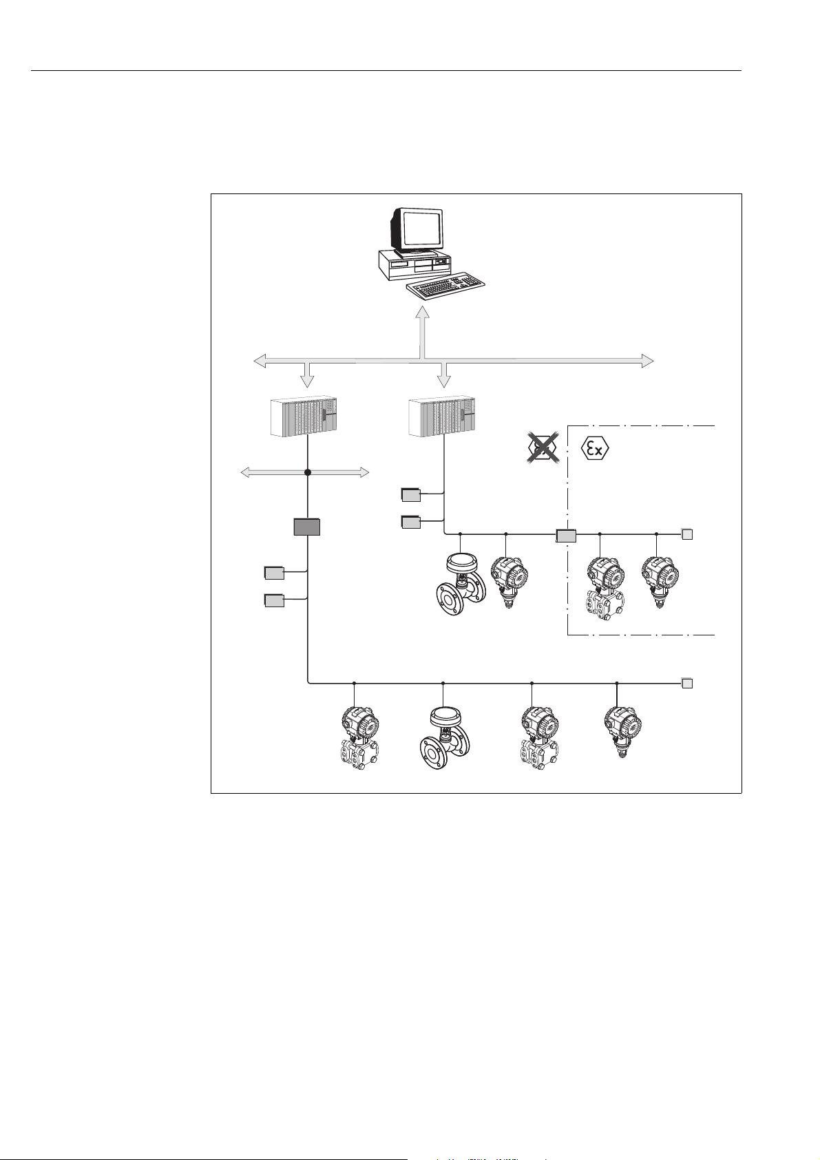
5.3 FOUNDATION Fieldbus interface
5.3.1 System architecture
!
P01-xxxxxxxx-02-xx-xx-xx-001
Fig. 12: FOUNDATION Fieldbus system architecture with associated components
FF-HSE: High Speed Ethernet, FF-H1: FOUNDATION Fieldbus-H1, LD: Linking Device FF-HSE/FF-H1,
PS: bus power supply unit, SB: safety barrier, BT: bus terminator
The system can be connected in the following ways:
– A linking device makes the connection to higher-order fieldbus levels (e.g. High Speed Ethernet (HSE)) possible.
– An FF-H1 connecting card is needed for direct connection to a process control system.
Note!
Further information on FOUNDATION Fieldbus can be found in Operating Instructions BA00013S
"FOUNDATION Fieldbus Overview, Installation and Commissioning Guidelines", the
FOUNDATION Fieldbus Specification or on the Internet at "http://www. fieldbus.org".
24 Endress+Hauser

Deltapilot S FMB70 with FOUNDATION Fieldbus Operation
5.3.2 Number of devices
• The Endress+Hauser Deltapilot S devices meet the requirements of the FISCO model.
• Due to the low current consumption, the following number of devices can be operated on one bus segment if installing to FISCO:
– Up to 6 Deltapilot S for Ex ia, CSA and FM IS applications
– Up to 24 Deltapilot S in all other applications, e.g. in non-hazardous areas, Ex nA etc.
The maximum number of measuring devices at one bus segment is defined by their current consumption, the performance of the bus coupler, and the required bus length.
5.3.3 Operation
You can obtain special configuration and operating programs from various manufacturers for the configuration, such as the FieldCare operating program from Endress+Hauser See ä 39, Section 5.5 "FieldCare". These configuration programs make it possible to configure FF functions and all the device-specific parameters. The predefined function blocks allow uniform access to all the network and device data.
5.3.4 Network configuration
!
You require the following to configure a device and integrate it into an FF network:
• An FF configuration program
• The Cff file (Common File Format: *.cff, *.fhx)
• The device description (Device Description: *.sym, *.ffo, *.sy5, *.ff5)
Pre-defined standard DDs, which can be obtained from FOUNDATION Fieldbus, are available for the basic functions of measuring devices. You require the device-specific DD to be able to access all the functions.
The files for Deltapilot S can be acquired as follows:
• Internet Endress+Hauser: http://www.de.endress.com Search for FOUNDATION Fieldbus
• Internet FOUNDATION Fieldbus: http://www.fieldbus.org
• On CD-ROM from Endress+Hauser, order number: 56003896
The device is integrated into the FF network as follows:
• Start the FF configuration program.
• Download the Cff and device description files (*.ffo, *.sym, *.cff or *.fhx files) to the system.
• Configure the interface, see Note.
• Configure the device for the measuring task and for the FF system.
Note!
• For more in-depth information on integrating the device into the FF system, see the description for the configuration software used.
• When integrating the field devices into the FF system, make sure you are using the right files. You can read out the required version by means of the DEV_REV and DD_REV parameters in the Resource Block.
Endress+Hauser 25
Operation Deltapilot S FMB70 with FOUNDATION Fieldbus
–
–
RS_XXXXXXXXXXX (RB2)
EH_DeltapilotS-XXXXXXXXXXXXXXXX
➀➁
TRD1_ (PCD)XXXXXXXXXXX
SERVICE_ (SERVICE)XXXXXXXXXXX
DIAGNOSTIC_ (DIAGNOSTIC)XXXXXXXXXXX
DISPLAY_ (DISP)XXXXXXXXXXX
AI1_ (AI)XXXXXXXXXXX
AI2_ (AI)XXXXXXXXXXX
DO_ (DO)XXXXXXXXXXX
PID_ (PID)XXXXXXXXXXX
ARTH_ (ARB)XXXXXXXXXXX
CHAR_ (SCB)XXXXXXXXXXX
ISEL_ (ISB)XXXXXXXXXXX
INTG_ (ITB)XXXXXXXXXXX
AALM_ (AALB)XXXXXXXXXXX
DI_ (DI)XXXXXXXXXXX
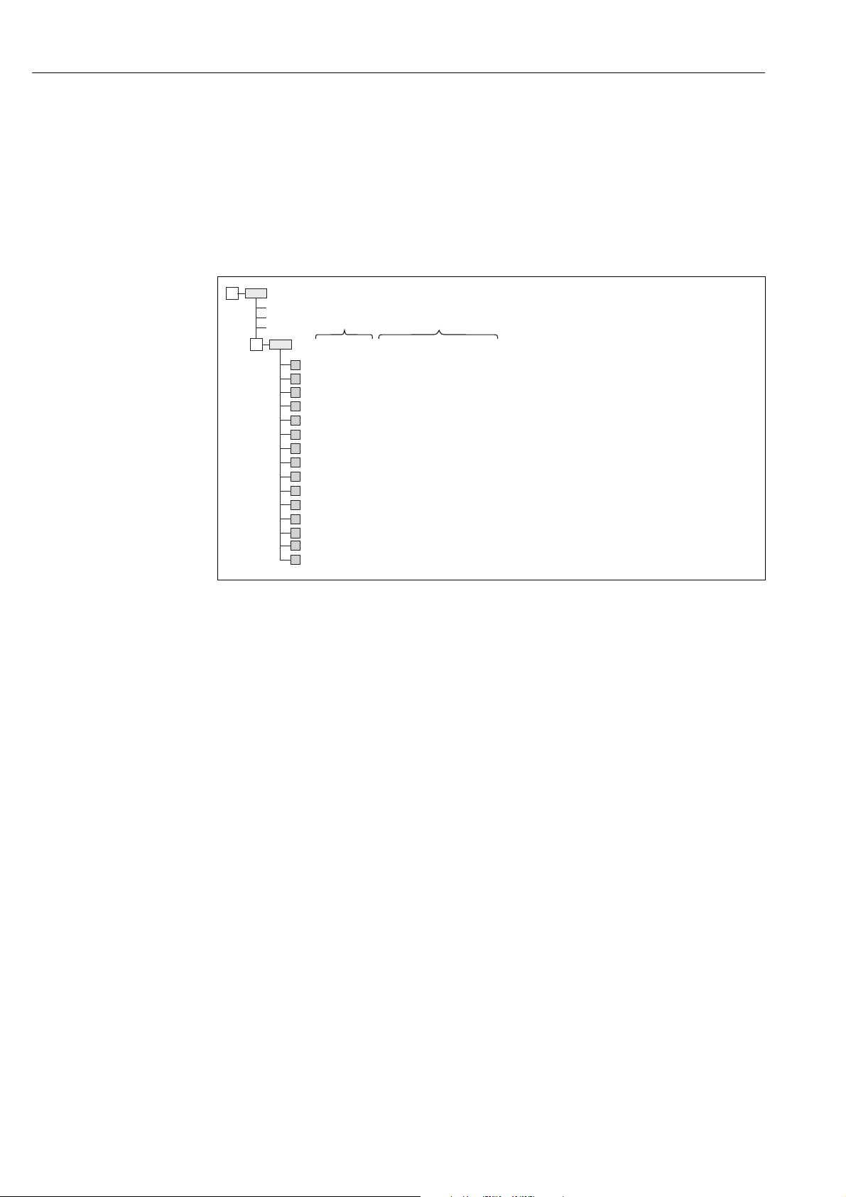
5.3.5 Device identification and addressing
FOUNDATION Fieldbus identifies the device using its ID code and automatically assigns it a suitable
field address. The identity code cannot be changed.
The device appears in the network display once you have started the FF configuration program and
integrated the device into the network. The blocks available are displayed under the device name.
If the device description has not yet been loaded, the blocks report "Unknown" or "(UNK)".
Deltapilot S reports as follows:
P01-PMx7xxxx-05-xx-xx-xx-017
Fig. 13: Typical Deltapilot S display in a configuration program after the connection has been established.
1 Device name 2 Serial number
5.3.6 Deltapilot S block model
With FOUNDATION Fieldbus, all the device parameters are categorized according to their functional properties and task and are generally assigned to three different blocks.
A FOUNDATION Fieldbus device has the following block types:
• A Resource Block (device block):
This block contains all the device-specific features of the device.
• One or more Transducer Blocks
A Transducer Block contains all the measuring and device-specific parameters of the device. The
measuring principles, such as pressure or totalizers, are mapped in the Transducer Blocks.
• One or more function blocks:
Function blocks contain the automation functions of the device. A distinction is made between
different function blocks such as the Analog Input Block or Proportional Integral Differential Block
26 Endress+Hauser
(PID). Each of these function blocks is used to execute different application functions.
The function blocks can be connected by means of an FF configuration program, depending on the automation task. The device thus takes on simple control functions, thereby relieving the workload on the higher-order process control system.

Deltapilot S FMB70 with FOUNDATION Fieldbus Operation
Deltapilot S has the following blocks:
• Resource Block (device block)
• 4 Transducer Blocks
– Pressure Transducer Block (TRD)
This Block supplies the output variables PRIMARY_VALUE and SECONDARY_VALUE. It
contains all the parameters to configure the measuring device for the measuring task such as
measuring mode selection, linearization function and unit selection.
– Service Transducer Block
This Block supplies the output variables COUNTER P_PMAX, PRESSURE_1_ MAX_
RESETABLE and PRESSURE_1_AFTER_DAMPING. It also includes all the counters for
measuring range overshoot/undershoot for pressure and temperature, minimum and
maximum measured values for pressure and temperature and the HistoROM function.
– Display Transducer Block
This Block does not return any output variables. It contains all the parameters for configuring the onsite display such as DISPLAY_CONTRAST.
– Diagnostic Transducer Block
This Block does not return any output variables. It contains
– the simulation function for the Pressure Transducer Block
– parameters to configure the alarm response
– parameters to set the user limits for pressure and temperature.
• 8 function blocks
– 2 Analog Input Blocks (AI)
– Discrete Input Block (DI)
– Discrete Output Block (DO)
– PID Block (PID)
– Arithmetic Block (ARB)
– Signal Characterizer Block (SCB)
– Input Selector Block (ISB)
– Analog Alarm Block (AALB)
– Integrator Block (IT)
!
In addition to the pre-instanced blocks already mentioned, the following blocks can also be instanced:
• 3 Analog Input Blocks (AI)
• 1 Discrete Output Block (DO)
• 1 PID Block (PID)
• 1 Arithmetic Block (ARB)
• 1 Signal Characterizer Block (SCB)
• 1 Input Selector Block (ISB)
• 1 Analog Alarm Block (AALB)
• 1 Integrator Block (IT)
A total of 20 blocks can be instanced in Deltapilot S altogether, including the blocks already instanced. For instancing blocks, see the appropriate Operating Instructions of the configuration program used.
Note!
Endress+Hauser Guideline BA00062S.
The guideline provides an overview of the standard function blocks that are described in
FOUNDATION Fieldbus Specifications FF 890 - 894.
It is designed to help operators use the blocks implemented in the Endress+Hauser field devices.
Endress+Hauser 27
 Loading...