

Endress+Hauser Cerabar S PMC71, Cerabar S PMP75, Cerabar S PMP72, Cerabar S PMP71 Technical Information
Page 1
Technical Information
Cerabar S PMC71, PMP71/72/75
Pressure transmitter
with ceramic and metal sensors
Overload-resistant and function-monitored; Communication via
HART, PROFIBUS PA or FOUNDATION Fieldbus
Application
The Cerabar S pressure transmitter is used for the
following measuring tasks:
• Absolute pressure and gauge pressure in gases, steams
or liquids in all areas of process engineering and
process measurement technology
• Level, volume or mass measurement in liquids
• High process temperature
– without diaphragm seals up to 150°C (302°F)
– with typical diaphragm seals up to 350°C (662°F)
• High pressure up to 700 bar
• International usage thanks to a wide range of approvals
Your benefits
• Very good reproducibility and long-term stability
• High reference accuracy: up to ±0.075%,
as PLATINUM version: ±0.05%
• Turn down 100:1, higher on request
• Meets PED (Pressure Equipment Directive)
• Used for process pressure monitoring up to SIL 2,
certified according to IEC 61508 by TÜV SÜD
•HistoROM
• Function-monitored from the measuring cell to the
electronics
• Continuous modularity for differential pressure and
pressure (Deltabar S – Cerabar S), e.g.
– replaceable display
– universal electronic
• Quick commissioning thanks to quick setup menu
• Easy and safe menu-guided operation on-site,
via 4...20 mA with HART, via PROFIBUS PA or
via FOUNDATION Fieldbus
• Extensive diagnostic functions
• Device versions in conformity with ASME-BPE
®
/M-DAT memory module
TI383P/00/en
Page 2

Table of contents
Cerabar S
Function and system design. . . . . . . . . . . . . . . . . . . . . 4
Device selection . . . . . . . . . . . . . . . . . . . . . . . . . . . . . . . . . . . . . . 4
Overview of diaphragm seal for PMP75 . . . . . . . . . . . . . . . . . . . . 5
Measuring principle . . . . . . . . . . . . . . . . . . . . . . . . . . . . . . . . . . . 7
Level measurement (level, volume and mass) . . . . . . . . . . . . . . . . 8
Communication protocol . . . . . . . . . . . . . . . . . . . . . . . . . . . . . . . 8
Human interface . . . . . . . . . . . . . . . . . . . . . . . . . . . . . 9
On-site display (optional) . . . . . . . . . . . . . . . . . . . . . . . . . . . . . . . 9
Operating elements . . . . . . . . . . . . . . . . . . . . . . . . . . . . . . . . . . 10
HistoROM®/M-DAT (optional) . . . . . . . . . . . . . . . . . . . . . . . . . 11
Functional Safety SIL2/IEC 61508 Declaration of conformity
(optional) . . . . . . . . . . . . . . . . . . . . . . . . . . . . . . . . . . . . . . . . . . 11
On-site operation . . . . . . . . . . . . . . . . . . . . . . . . . . . . . . . . . . . . 11
Handheld terminals – HART . . . . . . . . . . . . . . . . . . . . . . . . . . . . 11
Handheld terminal DXR375 – FOUNDATION Fieldbus . . . . . . . 11
ToF Tool – HART, PROFIBUS PA, FOUNDATION Fieldbus . . . . 12
FieldCare – HART, PROFIBUS PA . . . . . . . . . . . . . . . . . . . . . . . 12
Remote operation – FOUNDATION Fieldbus . . . . . . . . . . . . . . . 12
Service interface FXA193 . . . . . . . . . . . . . . . . . . . . . . . . . . . . . . 12
Input . . . . . . . . . . . . . . . . . . . . . . . . . . . . . . . . . . . . . 13
Measured variable . . . . . . . . . . . . . . . . . . . . . . . . . . . . . . . . . . . 13
Measuring range . . . . . . . . . . . . . . . . . . . . . . . . . . . . . . . . . . . . 13
Explanation of terms . . . . . . . . . . . . . . . . . . . . . . . . . . . . . . . . . . 15
Output . . . . . . . . . . . . . . . . . . . . . . . . . . . . . . . . . . . . 16
Output signal . . . . . . . . . . . . . . . . . . . . . . . . . . . . . . . . . . . . . . . 16
Signal range – 4...20 mA HART . . . . . . . . . . . . . . . . . . . . . . . . . 16
Signal on alarm . . . . . . . . . . . . . . . . . . . . . . . . . . . . . . . . . . . . . 16
Load – 4...20 mA HART . . . . . . . . . . . . . . . . . . . . . . . . . . . . . . . 16
Resolution . . . . . . . . . . . . . . . . . . . . . . . . . . . . . . . . . . . . . . . . . 17
Reading cycle . . . . . . . . . . . . . . . . . . . . . . . . . . . . . . . . . . . . . . 17
Cycle time (Update time) . . . . . . . . . . . . . . . . . . . . . . . . . . . . . . 17
Response time . . . . . . . . . . . . . . . . . . . . . . . . . . . . . . . . . . . . . . 17
Damping . . . . . . . . . . . . . . . . . . . . . . . . . . . . . . . . . . . . . . . . . . 17
Power supply . . . . . . . . . . . . . . . . . . . . . . . . . . . . . . . 18
Electrical connection 4...20 mA HART . . . . . . . . . . . . . . . . . . . . 18
Supply voltage . . . . . . . . . . . . . . . . . . . . . . . . . . . . . . . . . . . . . . 20
Current consumption . . . . . . . . . . . . . . . . . . . . . . . . . . . . . . . . . 20
Cable entry . . . . . . . . . . . . . . . . . . . . . . . . . . . . . . . . . . . . . . . . 20
Cable specification . . . . . . . . . . . . . . . . . . . . . . . . . . . . . . . . . . . 20
Residual ripple . . . . . . . . . . . . . . . . . . . . . . . . . . . . . . . . . . . . . . 20
Influence of power supply . . . . . . . . . . . . . . . . . . . . . . . . . . . . . . 20
Performance characteristics – general . . . . . . . . . . . . 21
Reference operating conditions . . . . . . . . . . . . . . . . . . . . . . . . . . 21
Uncertainty of measurement for small absolute pressure ranges . . 21
Long-term stability . . . . . . . . . . . . . . . . . . . . . . . . . . . . . . . . . . . 21
Influence of the installation position . . . . . . . . . . . . . . . . . . . . . . 21
Performance characteristics – ceramic diaphragm. . . 22
Reference accuracy – PMC71 . . . . . . . . . . . . . . . . . . . . . . . . . . . 22
Total performance – PMC71 . . . . . . . . . . . . . . . . . . . . . . . . . . . 22
Warm-up period – PMC71 . . . . . . . . . . . . . . . . . . . . . . . . . . . . . 23
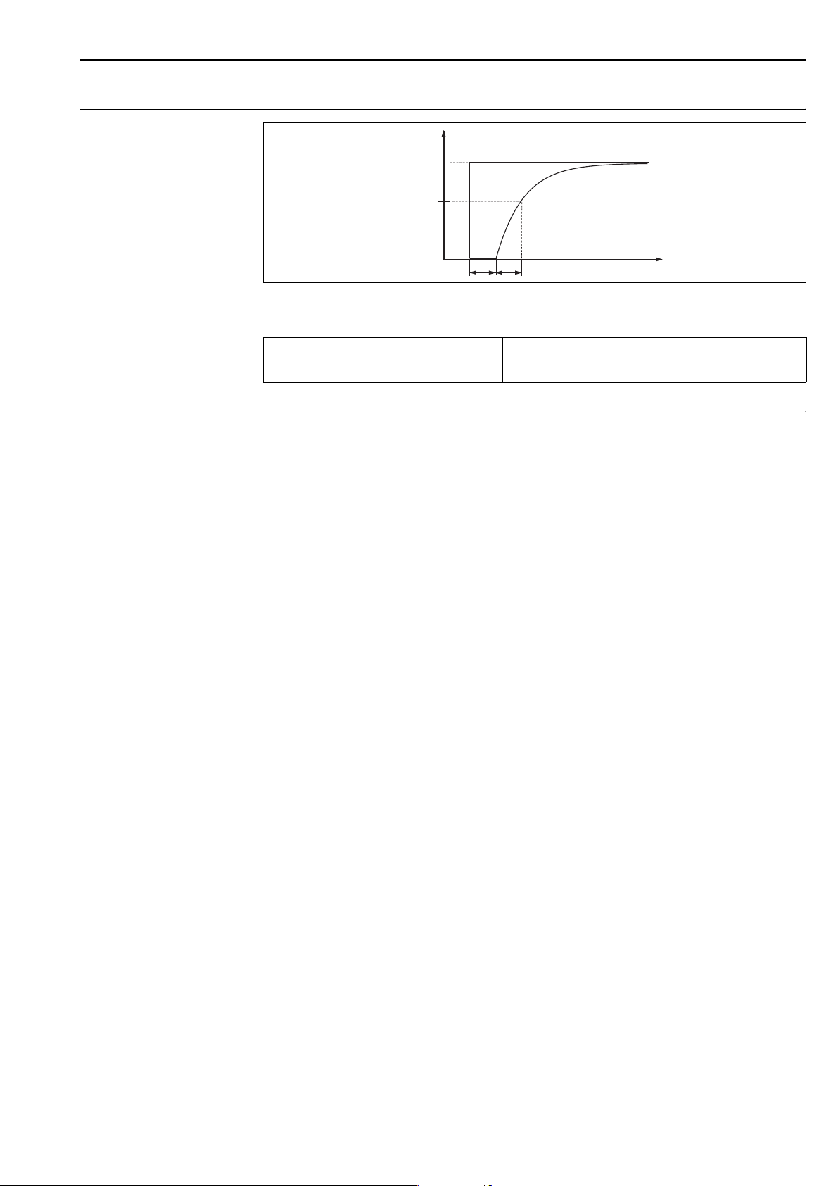
Dead time, Time constant (T63) – PMC71 . . . . . . . . . . . . . . . . . 23
Thermal change of the zero output and the output span –
PMC71 . . . . . . . . . . . . . . . . . . . . . . . . . . . . . . . . . . . . . . . . . . . 23
Performance characteristics – metallic diaphragm. . . 24
Reference accuracy – PMP71, PMP75 . . . . . . . . . . . . . . . . . . . . 24
Total performance – PMP71 . . . . . . . . . . . . . . . . . . . . . . . . . . . 25
Warm-up period – PMP71, PMP75 . . . . . . . . . . . . . . . . . . . . . . 25
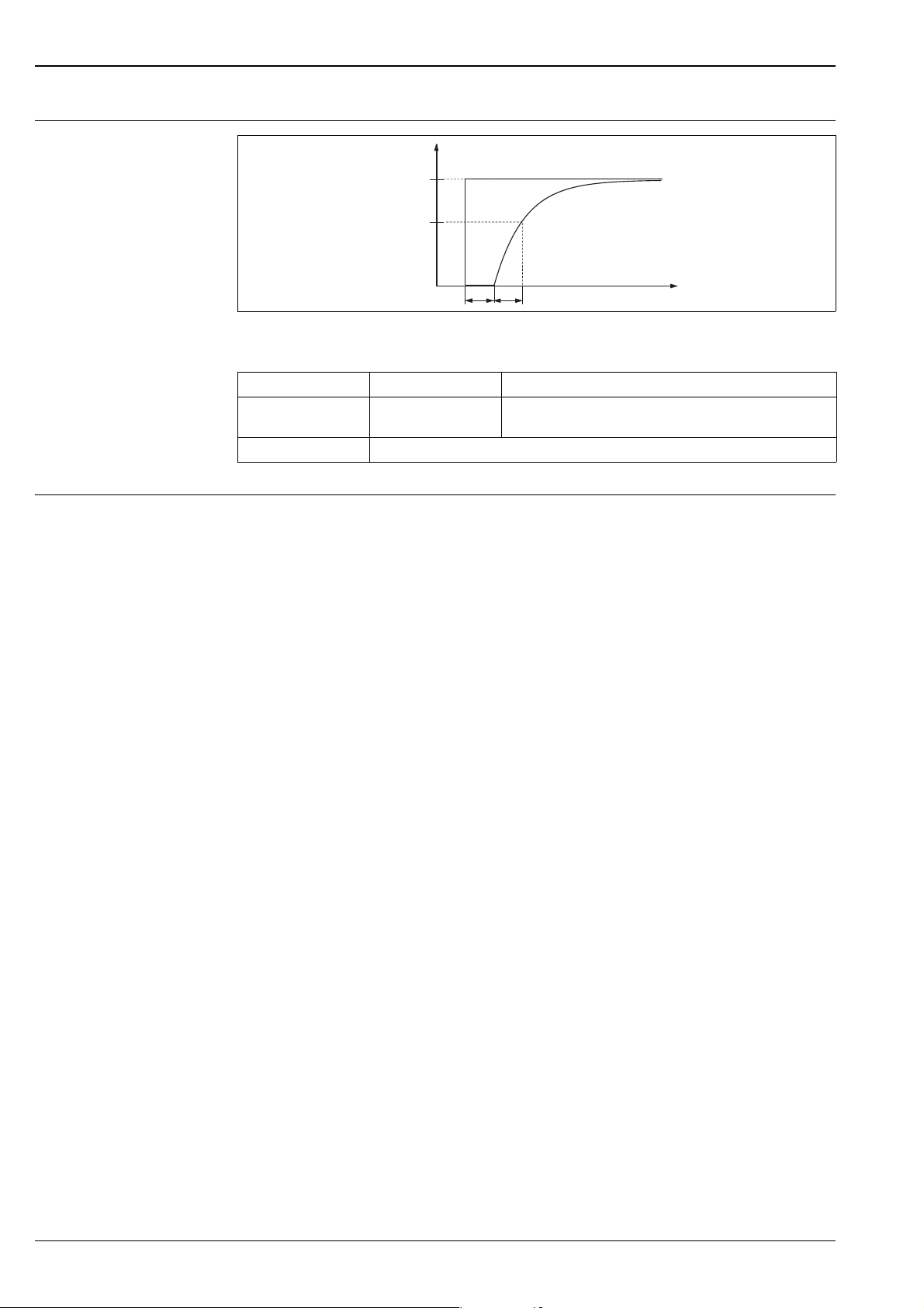
Dead time, Time constant (T63) – PMP71, PMP75 . . . . . . . . . . 26
Thermal change of the zero output and the output span –
PMP71 . . . . . . . . . . . . . . . . . . . . . . . . . . . . . . . . . . . . . . . . . . . 26
Operating conditions (installation) . . . . . . . . . . . . . . 27
General installation instructions . . . . . . . . . . . . . . . . . . . . . . . . . 27
Installation instructions for devices without diaphragm seal –
PMC71 and PMP71 . . . . . . . . . . . . . . . . . . . . . . . . . . . . . . . . . . 27
Heat insulation – PMC71 high temperature version and PMP75 . 27
Mounting with temperature isolator . . . . . . . . . . . . . . . . . . . . . . 28
Wall and pipe-mounting . . . . . . . . . . . . . . . . . . . . . . . . . . . . . . . 28
Turn the housing . . . . . . . . . . . . . . . . . . . . . . . . . . . . . . . . . . . . 29
Oxygen applications . . . . . . . . . . . . . . . . . . . . . . . . . . . . . . . . . . 29
Ultra pure gas applications . . . . . . . . . . . . . . . . . . . . . . . . . . . . . 30
Diaphragm seals for materials with hydrogen build-up
(Gold-Rhodium coating) . . . . . . . . . . . . . . . . . . . . . . . . . . . . . . . 30
Operating conditions (environment) . . . . . . . . . . . . . 30
Ambient temperature limits . . . . . . . . . . . . . . . . . . . . . . . . . . . . 30
Storage temperature range . . . . . . . . . . . . . . . . . . . . . . . . . . . . . 30
Degree of protection . . . . . . . . . . . . . . . . . . . . . . . . . . . . . . . . . 30
Climate class . . . . . . . . . . . . . . . . . . . . . . . . . . . . . . . . . . . . . . . 30
Vibration resistance. . . . . . . . . . . . . . . . . . . . . . . . . . . . . . . . . . 31
Electromagnetic compatibility . . . . . . . . . . . . . . . . . . . . . . . . . . 31
Overvoltage protection . . . . . . . . . . . . . . . . . . . . . . . . . . . . . . . . 31
Operating conditions (Process) . . . . . . . . . . . . . . . . . 32
Process temperature limits . . . . . . . . . . . . . . . . . . . . . . . . . . . . . 32
Temperature operating range, seals . . . . . . . . . . . . . . . . . . . . . . 32
Pressure specifications . . . . . . . . . . . . . . . . . . . . . . . . . . . . . . . . 33
Mechanical construction . . . . . . . . . . . . . . . . . . . . . . 34
Housing dimensions T14 . . . . . . . . . . . . . . . . . . . . . . . . . . . . . . 34
Housing dimensions T17 . . . . . . . . . . . . . . . . . . . . . . . . . . . . . . 34
Process connections PMC7 . . . . . . . . . . . . . . . . . . . . . . . . . . . . . 35
Process connections PMP71 . . . . . . . . . . . . . . . . . . . . . . . . . . . . 42
PMP75 Basic unit . . . . . . . . . . . . . . . . . . . . . . . . . . . . . . . . . . . 49
Process connections PMP75 . . . . . . . . . . . . . . . . . . . . . . . . . . . . 49
Weight . . . . . . . . . . . . . . . . . . . . . . . . . . . . . . . . . . . . . . . . . . . 61
Material . . . . . . . . . . . . . . . . . . . . . . . . . . . . . . . . . . . . . . . . . . . 61
2
Endress+Hauser
Page 3

Planning instructions, diaphragm seal systems . . . . . 62
Applications . . . . . . . . . . . . . . . . . . . . . . . . . . . . . . . . . . . . . . . . 62
Planning instructions . . . . . . . . . . . . . . . . . . . . . . . . . . . . . . . . . 62
Diaphragm seal filling oils . . . . . . . . . . . . . . . . . . . . . . . . . . . . . 63
Influence of the temperature on the zero point . . . . . . . . . . . . . . 63
Ambient temperature range . . . . . . . . . . . . . . . . . . . . . . . . . . . . 67
Installation instructions . . . . . . . . . . . . . . . . . . . . . . . . . . . . . . . 67
Certificates and approvals . . . . . . . . . . . . . . . . . . . . . 69
CE mark . . . . . . . . . . . . . . . . . . . . . . . . . . . . . . . . . . . . . . . . . . 69
Ex approvals . . . . . . . . . . . . . . . . . . . . . . . . . . . . . . . . . . . . . . . 69
Marine certificate . . . . . . . . . . . . . . . . . . . . . . . . . . . . . . . . . . . 69
Overspill protection . . . . . . . . . . . . . . . . . . . . . . . . . . . . . . . . . . 69
CRN approvals . . . . . . . . . . . . . . . . . . . . . . . . . . . . . . . . . . . . . 69
Pressure Equipment Directive (PED) . . . . . . . . . . . . . . . . . . . . . 69
Standards and guidelines . . . . . . . . . . . . . . . . . . . . . . . . . . . . . . 69
Ordering information . . . . . . . . . . . . . . . . . . . . . . . . 70
PMC71 . . . . . . . . . . . . . . . . . . . . . . . . . . . . . . . . . . . . . . . . . . . 70
PMP71 . . . . . . . . . . . . . . . . . . . . . . . . . . . . . . . . . . . . . . . . . . . 74
PMP75 . . . . . . . . . . . . . . . . . . . . . . . . . . . . . . . . . . . . . . . . . . . 78
Cerabar S
Documentation . . . . . . . . . . . . . . . . . . . . . . . . . . . . . 82
Innovation . . . . . . . . . . . . . . . . . . . . . . . . . . . . . . . . . . . . . . . . . 82
Field of Activities . . . . . . . . . . . . . . . . . . . . . . . . . . . . . . . . . . . . 82
Technical Information . . . . . . . . . . . . . . . . . . . . . . . . . . . . . . . . 82
Operating Instructions . . . . . . . . . . . . . . . . . . . . . . . . . . . . . . . . 82
Manual for Functional Safety (SIL) . . . . . . . . . . . . . . . . . . . . . . . 82
Safety Instructions . . . . . . . . . . . . . . . . . . . . . . . . . . . . . . . . . . . 82
Installation/Control Drawings . . . . . . . . . . . . . . . . . . . . . . . . . . 83
Overspill protection . . . . . . . . . . . . . . . . . . . . . . . . . . . . . . . . . . 83
Endress+Hauser
3
Page 4
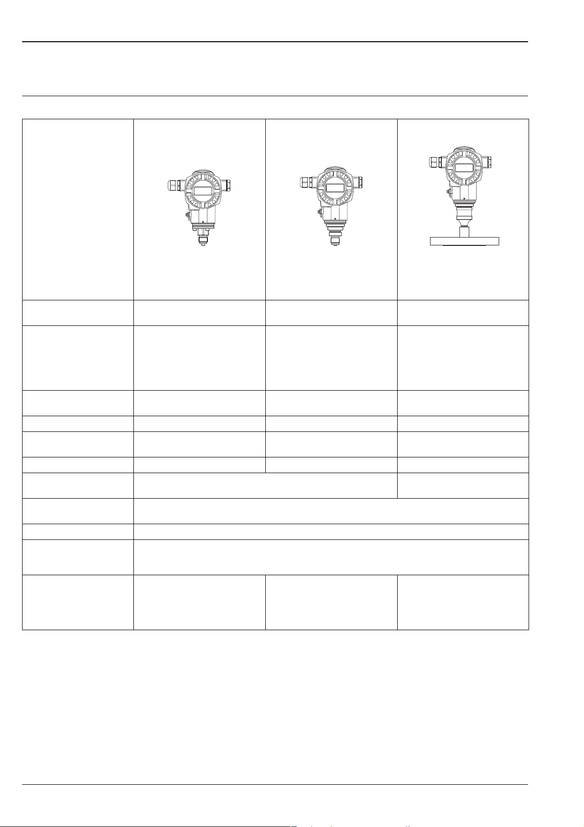
Device selection
Cerabar S
Function and system design
Cerabar S –
PMC71
PMP71
Product family
P01-PMC71xxx-16-xx-xx-xx-000
With capacitive measuring cell and
ceramic measuring diaphragm
(Ceraphire
®
)
Field of application – Gauge pressure and absolute pressure
– Level
Process connections – Diverse thread
– DN 32 – DN 80
– ANSI 1 1/2" – 4"
– JIS 50 A – 100 A
With piezoresistive measuring cell
and metallic welded diaphragm
– Gauge pressure and absolute pressure
– Level
–Diverse thread
– DN 25 – DN 80
– ANSI 1 1/2" – 4"
– JIS 25 A – 100 A
P01-PMP71xxx-16-xx-xx-xx-000
– Oval flange adapter
– Prepared for diaphragm seal mount
Measuring ranges from –0.1/0...100 mbar
to –1/0...40 bar
1
OPL
Process temperature –20...+125°C/–20...+150°C
max. 60 bar max. 1050 bar max. 1050 bar
2
(–4...+257°F/–4...+302°C)
Ambient temperature –40...+85°C (–40...+185°F) –40...+85°C (–40...+185°F)
from –0.1/0...100 mbar
to –1/0...700 bar
–40...+125°C
(–40...+257°F)
3
–40...+85°C (–40...+185°F)
Reference accuracy – Up to ±0.075% of the set span
–PLATINUM version: up to ±0.05% of the set span
Supply voltage – For non-hazardous areas: 10.5...45 V DC
– EEx ia: 10.5...30 V DC
Output 4...20 mA with superimposed HART protocol, PROFIBUS PA, FOUNDATION Fieldbus
Options – PMP71, PMP75: Gold-Rhodium-coated diaphragm
– PMP71, PMP75: NACE-compliant materials
– PMC71, PMP71, PMP75: inspection certificate 3.1
Specialities – Metal-free measurement with PVDF
connection
– Oil volume-minimised process
connections
– gas-tight, elastomer-free
PMP75
P01-PMP75xxx-16-xx-xx-xx-000
With diaphragm seal
– Gauge pressure and absolute pressure
– Level
– Wide range of diaphragm seals, → see
the following section "Overview of
diaphragm seal for PMP 75"
from –0.1/0...400 mbar
to –1/0...700 bar
With diaphragm seal up to +350°C
(+662°F)
Up to ±0.075% of the set span
– Wide range of diaphragm seals
– For high media temperatures
– Oil volume-minimised process
connections
– Completely welded versions
1) OPL = Over pressure limit; dependent on the lowest-rated element, with regard to pressure, of the selected components
2) High temperature version "T" for feature 100 "Additional option 1" or for feature 110 "Additional option 2"
3) lower temperature on request
4 Endress+Hauser
Page 5
Cerabar S
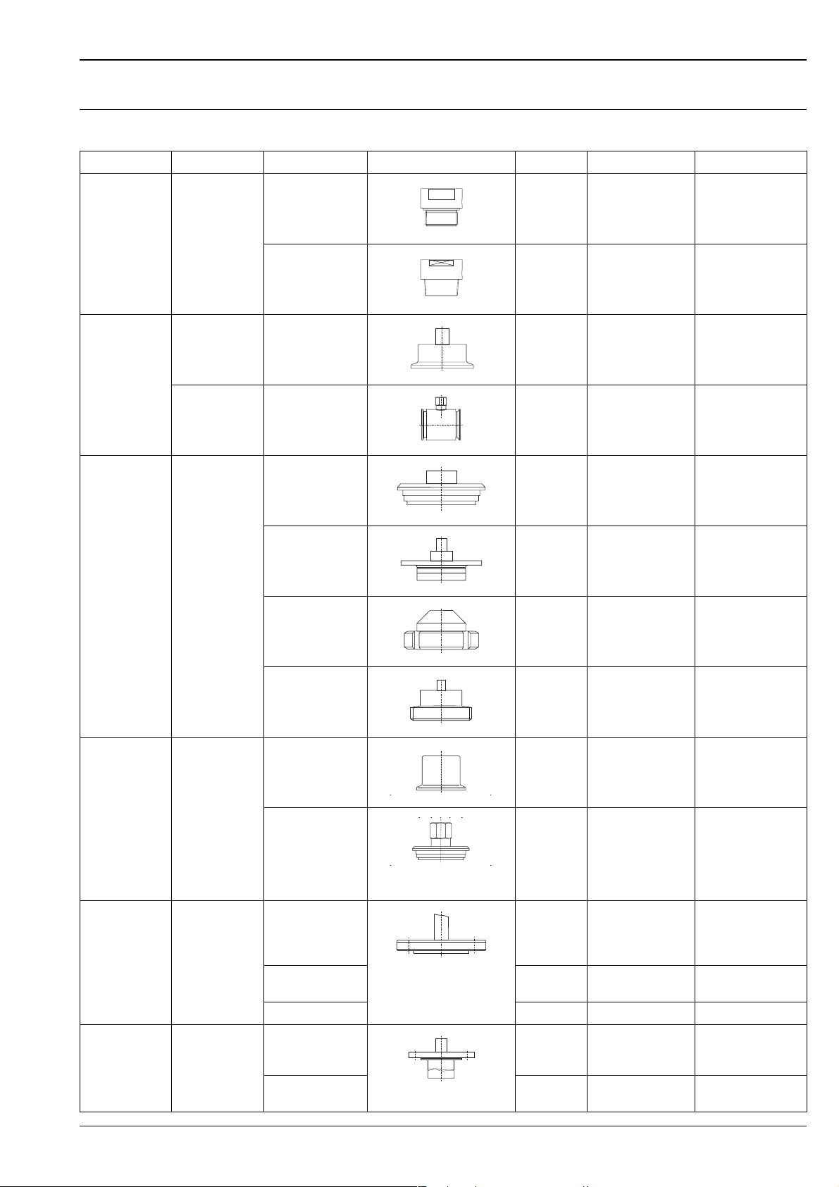
Overview of diaphragm seal for PMP75
Design Diaphr. seal Connection Version Standard Nominal diameter Nom. press./Class
Thread Membrane
diaphragm seal
(MDM)
Tri-Clamp Membrane
diaphragm seal
(MDM)
Pipe diaphragm
seal (RDM)
Front-flush
connections
Membrane
diaphragm seal
(MDM)
G
NPT
Clamp
Clamp
Varivent
DRD
P01-PMP75xxx-03-xx-xx-xx-005
P01-PMP75xxx-03-xx-xx-xx-006
P01-FMD78xxx-03-xx-xx-xx-005
P01-FMD78xxx-03-xx-xx-xx-009
P01-FMD78xxx-03-xx-xx-xx-007
ISO 228 – G 1A
– G 1 1/2 A
–G 2A
ANSI – 1 MNPT
– 1 1/2 MNPT
–2 MNPT
ISO 2852 – DN 25 (1")
– DN 38 (1 1/2")
– DN 51 (2")
– DN 76.1 (3")
ISO 2852 – DN 25 (1")
– DN 38 (1 1/2")
– DN 51 (2")
Type N for pipes
DN 40 – DN 162
d = 65 mm 25 bar
700 bar
700 bar
Dependent on the
clamp used
Dependent on the
clamp used
PN 40
Versions in
conformity with
ASME-BPE for use
Membrane
diaphragm seal
(MDM)
in biotechnical
processes;
wetted surfaces
R
≤ 0.4 µm
a
(15.75 µin;
180 grit),
electropolished
Flange Membrane
diaphragm seal
(MDM)
Flange with
extended
diaphragm seal
Membrane
diaphragm seal
(MDM)
P01-FMD78xxx-03-xx-xx-xx-006
Taper adapter with
coupling nut
DIN 11851 – DN 50
–DN 65
PN 25
–DN 80
P01-FMD78xxx-03-xx-xx-xx-003
Threaded adapter
DIN 11851 – DN 50
PN 25
–DN 65
–DN 80
P01-FMD78xxx-03-xx-xx-xx-004
Clamp
P01-PMP46xxx-03-xx-xx-xx-005
Varivent
ISO 2852 – DN 25 (1 1/2")
– DN 51 (2" )
– Type N for pipes
Dependent on the
clamp used
PN 40
DN 40 – DN 162
P01-PMP46xxx-03-xx-xx-xx-004
EN/DIN flange
P01-PMP75xxx-03-xx-xx-xx-001
EN 1092-1/
DIN 2527
and
DIN 2501-1
– DN 25, DN 50
– DN 32, DN 40
–DN 80
– DN 100
ANSI flange ANSI B 16.5 – 1", 2"
– 1 1/2", 3", 4"
–up to PN 400
–PN 40
–up to PN 100
–PN 100
– 2500 lbs
– 300 lbs
JIS flange B 2220 25A, 50A, 80A, 100A 10 K
EN/DIN flange
EN 1092-1/
DIN 2527
DN 50/DN 80 +
50/100/200 mm ext.
PN 10 – PN 40
diaphr. seal
ANSI flange ANSI B 16.5 2"/3"/4" + 2"/4"/6"/
P01-PMP75xxx-03-xx-xx-xx-002
Up to 300 lbs
8" ext. diaphr. seal
Endress+Hauser 5
Page 6

Cerabar S
Design Diaphr. seal Connection Version Standard Nominal diameter Nom. press./Class
Threaded
connection with
separator
Membrane
diaphragm seal
(MDM)
G
NPT
NPT Off line thread
P01-PMP75xxx-03-xx-xx-xx-004
P01-PMP75xxx-03-xx-xx-xx-008
P01-PMP75xxx-03-xx-xx-xx-009
ISO 228/
EN837
– G 1/2 A
– G 1/2 B
– 160 bar
– 400 bar
ANSI – 1/2 MNPT – 160 bar
– 400 bar
ANSI – 1/2 NPT
250 bar
–1 NPT
6 Endress+Hauser
Page 7
Cerabar S
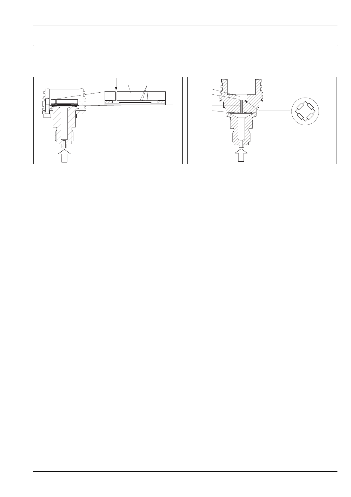
Measuring principle
Ceramic measuring diaphragm used for PMC71 (Ceraphire®) Metallic measuring diaphragm used for
PMP71 and PMP75
➂➀➁
➀
➁
➃
➂
➃
p
Ceramic sensor
1 Atmospheric vent (gauge pressure only)
2 Ceramic substrate
3 Electrodes
4 Ceramic diaphragm
Ceramic measuring diaphragm used for PMC71 (Ceraphire
The ceramic sensor is a dry sensor, i.e. the process pressure acts directly on the robust ceramic diaphragm and
deflects it. A pressure-dependent change in capacitance is measured at the electrodes of the ceramic carrier and
the diaphragm. The measuring range is determined by the thickness of the ceramic diaphragm.
Advantages:
• Guaranteed overload resistance up to 40 times the nominal pressure
• Thanks to highly-pure 99.9% ceramic (Ceraphire
– extremely high resistance compared to Alloy
–less relaxation
– high mechanical stability
• Suitable for vacuums
• Second process barrier (Secondary Containment) for enhanced integrity
• Process temperature up to 150°C (302°F)
P01-PMC71xxx-03-xx-xx-xx-000
Metal sensor
1 Measuring element
2 Measuring diaphragm with Wheatstone bridge
3 Channel with fill fluid
4 Process diaphragm, Metal separating diaphragm
®
)
p
®
)
P01-PMP7xxxx-03-xx-xx-xx-000
Metallic measuring diaphragm used for PMP71 and PMP75
PMP71
The operating pressure deflects the separating diaphragm and a fill fluid transfers the pressure to a resistance
measuring bridge (semi-conductor technology). The pressure-dependent change of the bridge output voltage
is measured and processed further.
Advantages:
• Can be used with process pressures up to 700 bar
• High long-term stability
• Guaranteed overload resistance up to 4 times the nominal pressure (PMP71)
• Second process barrier (Secondary Containment) for enhanced integrity
• Significantly less thermal effect compared to diaphragm seal systems
PMP75
The operating pressure acts on the diaphragm of the diaphragm seal and is transferred to the separating
diaphragm of the sensor by a diaphragm seal fill fluid. The separating diaphragm is deflected and a fill fluid
transfers the pressure to a resistance measuring bridge. The pressure-dependent change of the bridge output
voltage is measured and processed further.
Advantages:
• Can be used with process pressures from 400 mbar to 400 bar
• High long-term stability
• Guaranteed overload resistance up to 4 times the nominal pressure
• Second process barrier (Secondary Containment) for enhanced integrity
Endress+Hauser 7
Page 8
Cerabar S
Level measurement (level, volume and mass)
Design and operation mode
p
h=
ρ g
h
P01-PMx7xxxx-15-xx-xx-xx-000
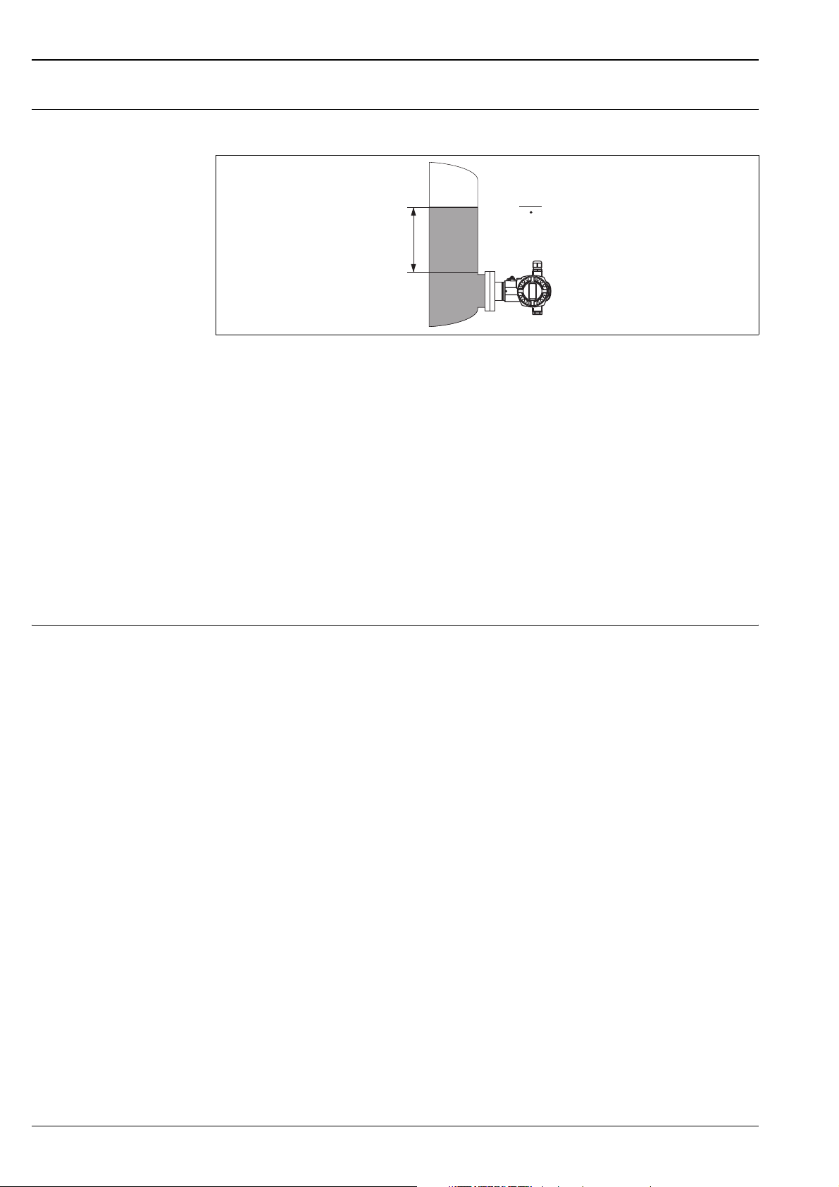
Level measurement with Cerabar S
h Height (level)
pPressure
ρ Density of the medium
g Gravitation constant
Your benefits
• Choice of three level operating modes
• Volume and mass measurements in any tank shapes by means of a freely programmable characteristic curve
• Choice of diverse level units with automatic unit conversion
• A customised unit can be specified
• Has a wide range of uses, e.g.
– in the event of foam formation
– in tanks with agitators of screen fittings
– in the event of liquid gases
– for standard level measurement
Communication protocol • 4...20 mA with HART communication protocol
• PROFIBUS PA
– The Endress+Hauser devices meet the requirements as per the FISCO model.
– Due to the low current consumption of 11 mA ± 1 mA
– up to 9 Cerabar S for EEx ia, CSA IS and FM IS applications
– up to 32 Cerabar S for all other applications, e.g. in non-hazardous areas, EEx nA, etc.
can be operated at one bus segment with installation as per FISCO.
Further information on PROFIBUS PA, such as requirements for bus system components, can be found in
the Operating Instructions BA034S "PROFIBUS DP/PA: Guidelines for planning and commissioning" and in
the PNO guideline.
• FOUNDATION Fieldbus
– The Endress+Hauser devices meet the requirements as per the FISCO model.
– Due to the low current consumption of 14 mA ± 1 mA
– up to 7 Cerabar S for EEx ia, CSA IS and FM IS applications
– up to 30 Cerabar S for all other applications, e.g. in non-hazardous areas, EEx nA, etc.
can be operated at one bus segment with installation as per FISCO.
Further information on FOUNDATION Fieldbus, such as requirements for bus system components can be
found in the Operating Instructions BA013S "FOUNDATION Fieldbus Overview".
8 Endress+Hauser
Page 9
Cerabar S
Human interface
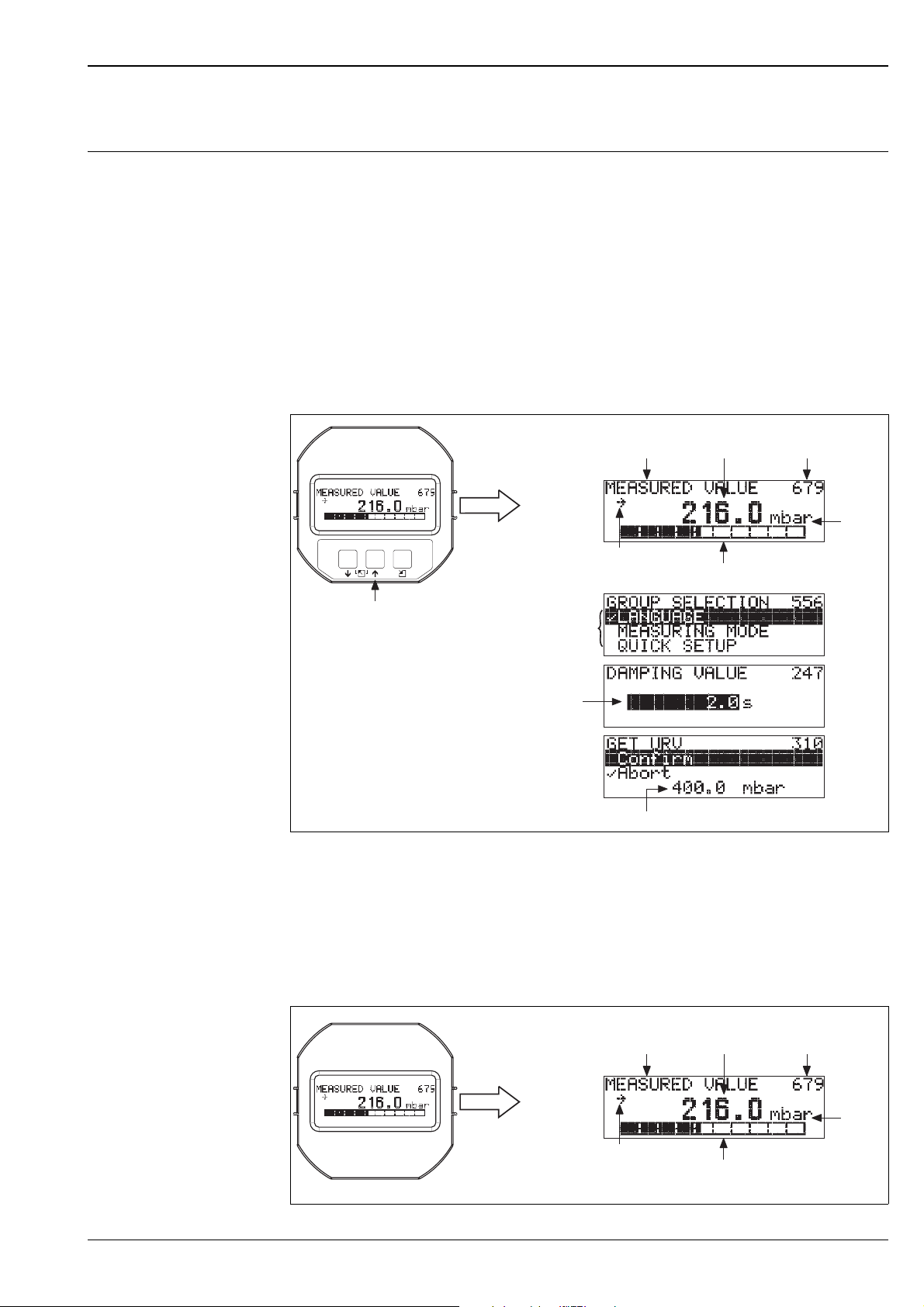
On-site display (optional) A 4-line liquid crystal display (LCD) is used for display and operation. The on-site display shows measured
values, dialog text as well as fault and notice messages in plain text, thereby supporting the user in every stage
of operation.
4...20 mA HART
Functions:
• 8-digit measured value display including sign and decimal point, bargraph for current display
• Simple and complete menu guidance thanks to separation of the parameters into three levels
• Each parameter is given a 3-digit ID number for easy navigation.
• Option for configuring the display according to individual requirements and desires, such as language,
alternating display, display of other measured values such as sensor temperature, contrast setting
• Comprehensive diagnostic functions (fault and warning message, peak-hold indicators, etc.)
• Rapid and safe commissioning with the Quick Setup menus
–
+
E
Operating keys
Measured value display
Header line
Main line
Information
line
Editing modes
Selection
options
Value that
can be edited
ValueFunction name
Symbol
Current measured value
Bargraph
Bargraph
Parameter
Identification
number
Unit
P01-xMx7xxxx-07-xx-xx-xx-001
PROFIBUS PA and FOUNDATION Fieldbus
Functions:
• 8-digit measured value display including sign and decimal point, bargraph for current display
• Option for configuring the display according to individual requirements and desires, such as language,
alternating display, display of other measured values such as sensor temperature, contrast setting
• Comprehensive diagnostic functions (fault and warning message)
Parameter
Identification
number
Unit
P01-xMD7xxxx-07-xx-xx-xx-001
Header line
Main line
Information
line
Measured value display
ValueFunction name
Symbol
Bargraph
Endress+Hauser 9
Page 10
Cerabar S
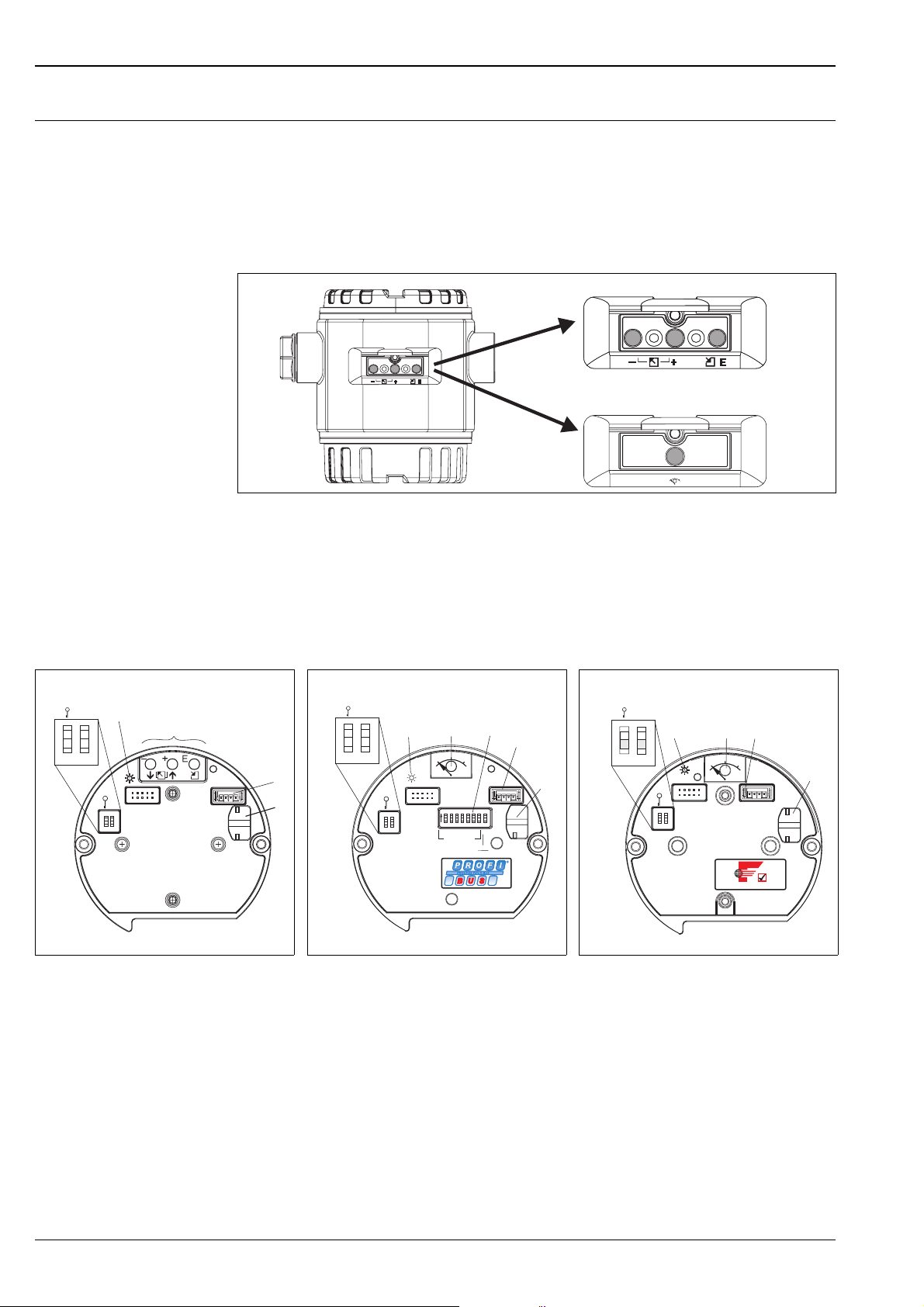
Operating elements With regard to T14 housings, the operating keys are located either outside the device under the protection cap
or inside on the electronic insert. In T17 housings, the operating keys are always located inside on the
electronic insert.
In addition, devices with an on-site display and a 4 to 20 mA HART electronic insert have operating keys on
the on-site display.
Operating keys on the exterior of the device
4...20 mA HART
PROFIBUS PA/
FOUNDATION Fieldbus
0%
Zero
P01-PMx7xxxx-19-xx-xx-xx-038
The operating keys located externally on the device work on the Hall sensor principle. As a result, no additional
openings are required in the device. This guarantees:
• Complete protection against environmental influences such as moisture and contamination
• Simple operation without any tools
•No wear.
Operating keys and elements located internally on the electronic insert
➄
➃
τ
on
off
Electronic insert HART
1Operating keys
2 Slot for optional display
3 Slot for optional HistoROM
4 DIP-switch for locking/unlocking
5 DIP-switch for damping on/off
6 Green LED to indicate value being accepted
➅
➀
Damping [ ]τ
Sensor
on
21
off
measured-value-relevant parameters
Display
P01-xxxxxxxx-19-xx-xx-xx-104
®
/M-DAT
➁
PC
ROM
Histo
➆➅
τ
on
off
➂
➀➁
0%
Sensor
Damping [ ]τ
on
on
off
21
off
Electronic insert PROFIBUS PA
1 Green LED to indicate value being accepted
2 Key for position calibration
3 DIP-switch for bus address
4 Slot for optional display
5 Slot for optional HistoROM
6 DIP-switch for locking/unlocking measured-
value-relevant parameters
7 DIP-switch for damping on/off
01
12
Zero
21
345 678
3
4
Address
CKON
5
➂
Display
SDA08
678
SW
HW
P01-xxxxxxxx-19-xx-xx-xx-105
®
/M-DAT
➃
PC
ROM
Histo
➅
➄
Sim.
on
off
➄
➀➁
2
1
Simulation
21
Sensor
on
off
0%
Zero
Electronic insert FOUNDATION Fieldbus
1 Green LED to indicate value being accepted
2 Key for position calibration
3 Slot for optional display
4 Slot for optional HistoROM
5 DIP-switch for locking/unlocking
measured-value-relevant parameters
6DIP-switch for simulation mode on/off
➂
Display
HW
F
OUNDATION
P01-xxxxxxxx-19-xx-xx-xx-106
®
/M-DAT
➃
PC
ROM
Histo
10 Endress+Hauser
Page 11

Cerabar S
HistoROM®/M-DAT
(optional)
Functional Safety SIL2/
IEC 61508 Declaration of
conformity (optional)
HistoROM®/M-DAT is a memory module, which is attached to the electronic insert. The HistoROM®/M-DAT
can be retrofitted at any stage (Order number: 52027785).
Your benefits
• Quick and safe commissioning of the same measuring points by copying the configuration data of one
transmitter to another transmitter
• Reliable process monitoring thanks to cyclical recording of pressure and sensor temperature measured values
• Simple diagnosis by recording diverse events such as alarms, configuration changes, counters for measuring
range undershoot and overshoot for pressure and temperature as well as user limit overshoot and undershoot
for pressure and temperature etc.
• Analysis and graphic evaluation of the events and process parameters via ToF Tool (contained in scope of
supply)
®
HistoROM
/M-DAT can be ordered via feature 100 "Additional options 1" or feature 110 "Additional
options 2" or as spare parts. → See also page 70 ff. A CD with the Endress+Hauser ToF Tool operating program
is also included in the scope of delivery.
You can copy data from one transmitter to another transmitter when operating a FOUNDATION Fieldbus
device via an FF configuration program. You need the Endress+Hauser ToF Tool operating program and the
FXA193 service interface to be able to access the data and events saved in the HistoROM
®
/M-DAT.
The Cerabar S pressure transmitters with 4...20 mA output signal have been developed to IEC 61508 standard
and have been certified by TÜV SÜD. These devices can be used for process pressure monitoring up to SIL 2.
→ For a detailed description of the safety functions with Cerabar S, settings and characteristic quantities for
functional safety, please refer to the "Manual for Safety Manual - Cerabar S" SD190P.
→ For devices with SIL2/IEC 61508 declaration of conformity, see page 73 ff, Feature 100 "Additional
option 1" and Feature 110 "Additional option 2", version E "SIL2/IEC 61508, Declaration of Conformity".
On-site operation Functions 4...20 mA HART
• With on-site display: navigate through the operating menu using three operating keys
• Without on-site display:
– Position calibration (zero point correction)
– Setting lower-range value and upper-range value – reference pressure present at device
– Value acceptance indicated by green LED
• Device reset
• Locking and unlocking measured-value-relevant parameters
• Switching damping on and off
Functions PROFIBUS PA
• Position calibration (zero point correction)
• Value acceptance indicated by green LED
• Locking and unlocking measured-value-relevant parameters
• Setting bus address
• Switching damping on and off
Functions FOUNDATION Fieldbus
• Position calibration (zero point correction)
• Value acceptance indicated by green LED
• Locking and unlocking measured-value-relevant parameters
• Switching simulation mode on and off
Handheld terminals – HART With a handheld terminal, all the parameters can be configured anywhere along the 4...20 mA line via menu
operation.
Handheld terminal DXR375 –
With a handheld terminal DXR375, all the parameters can be configured via menu operation.
FOUNDATION Fieldbus
Endress+Hauser 11
Page 12

Cerabar S
ToF Tool – HART, PROFIBUS PA, FOUNDATION Fieldbus
FieldCare – HART, PROFIBUS PA
!
The ToF Tool is a graphic and menu-guided operating program for measuring devices from
Endress+Hauser. It is used for the commissioning, data storage, signal analysis and documentation of the
devices. The following operating systems are supported: WinNT4.0, Win2000 and Windows XP. You can set
all parameters via the ToF Tool.
The ToF Tool supports the following functions:
• Configuration of transmitters in online operation
• Loading and saving device data (upload/download)
•HistoROM
• Calculation of tank characteristics for the level measuring mode
• Documentation of the measuring point
Connection options:
• HART via Commubox FXA191 and the serial interface RS 232 C of a computer
• HART via Commubox FXA195 and the USB interface of a computer
• PROFIBUS PA via segment coupler and PROFIBUS interface card
• FOUNDATION Fieldbus, PROFIBUS PA and HART: Service interface with adapter FXA193
Note!
You can use the ToF Tool to configure the Endress+Hauser parameters for devices with "FOUNDATION
Fieldbus signal". You need an FF configuration program to be able to configure all the FF-specific parameters
and to integrate the device into an FF network.
FieldCare is an Endress+Hauser asset management tool based on FDT technology. With FieldCare, you can
configure all Endress+Hauser devices as well as devices from other manufacturers that support the FDT
standard. The following operating systems are supported: WinNT4.0, Win2000 and Windows XP.
FieldCare supports the following functions:
• Configuration of transmitters in online operation
• Loading and saving device data (upload/download)
•HistoROM
• Documentation of the measuring point
Connection options:
• HART via Commubox FXA195 and the USB interface of a computer
• PROFIBUS PA via segment coupler and PROFIBUS interface card
®
/M-DAT analysis
®
/M-DAT analysis
Remote operation – FOUNDATION Fieldbus
Service interface FXA193 The FXA193 service interface connects Cerabar S, Deltabar S, ToF and PROline measuring devices (level and
An FF configuration program is required to integrate a device with "FOUNDATION Fieldbus signal" into an FF
network or to set the FF-specific parameters. Please contact your local Endress+Hauser Sales Center for more
information.
flow measuring devices) with the RS 232 C serial interface of a PC and thus makes it possible to operate the
measuring devices with the Endress+Hauser ToF Tool operating program. The FXA193 service interface is
connected to the interface for the local display on the electronic insert. → See also graphics on page 10.
12 Endress+Hauser
Page 13

Cerabar S
Input
Measured variable Absolute pressure and gauge pressure, from which level (level, volume or mass) is derived
®
Measuring range PMC71 – with ceramic measuring diaphragm (Ceraphire
) for gauge pressure
Nominal
value
Measurement limit Span OPL
1
MWP
2
Vacuum
resistance
Versions in
the order
code
lower (LRL) upper (URL) recommended
minimum
4
min./max.
[bar] [bar] [bar] [bar] [bar] [bar] [bar
abs
]
100 mbar –0.1 +0.1 0.01/0.1 0.005 4 2.7 0.7 1C
250 mbar –0.25 +0.25 0.017/0.25 0.005 5 3.3 0.5 1E
400 mbar –0.4 +0.4 0.027/0.4 0.005 8 5.3 0 1F
1 bar –1 +1 0.067/1 0.01 10 6.7 0 1H
2 bar –1 +2 0.133/2 0.02 18 12 0 1K
4 bar –1 +4 0.267/4 0.04 25 16.7 0 1M
10 bar –1 +10 0.67/10 0.1 40 26.7 0 1P
40 bar –1 +40 4/40 0.4 60 40 0 1S
®
) for absolute pressure
2
MWP
Versions in the order code
Nominal
PMC71 – with ceramic measuring diaphragm (Ceraphire
Measurement limit Span OPL
1
value
lower (LRL) upper (URL) recommended
minimum
4
min./max.
[bar
][bar
abs
] [bar] [bar] [bar
abs
][bar
abs
abs
]
100 mbar 0 +0.1 0.02/0.1 0.005 4 2 2C
250 mbar 0 +0.25 0.025/0.25 0.005 5 2.7 2E
400 mbar 0 +0.4 0.027/0.4 0.005 8 5.3 2F
1 bar 0 +1 0.067/1 0.01 10 6.7 2H
2 bar 0 +2 0.133/2 0.02 18 12 2K
4 bar 0 +4 0.267/4 0.04 25 16.7 2M
10 bar 0 +10 0.67/10 0.1 40 26.7 2P
40 bar 0 +40 4/40 0.4 60 40 2S
3
3
1) OPL: Over pressure limit (= Sensor overload limit)
2) The MWP (maximum working pressure) for the measuring device depends on the weakest element of the components selected with regard to pressure,
i.e. the process connection (
→
see page 34 ff) has to taken into consideration in addition to the sensor (→ see Table above). Pay attention to the pressure-
temperature dependence also. For the appropriate standards and further information, see page 33, "Pressure specification".
3) Versions in the order code → See also page 71 ff, feature 40 "Sensor range; Sensor overload limit (= OPL)"
4) minimum span that can be calibrated, Turn down > 100:1 on request
Endress+Hauser 13
Page 14

PMP71 and PMP75 – with metallic measuring diaphragm for gauge pressure
Cerabar S
Nominal
value
Measurement limits Span OPL
1
MWP
2
Vacuum
resistance
3
Versions in
the order
code
lower (LRL) 5upper (URL) recommended
minimum
min./max.
[bar] [bar] [bar] [bar] [bar
5
Silicone oil/
Inert oil
][bar
rel
][bar
rel
abs
]
100 mbar –0.1 +0.1 0.05/0.1 0.005 4 2.7 0.01/0.04 1C
250 mbar –0.25 +0.25 0.1/0.25 0.005 4 2.7 0.01/0.04 1E
400 mbar –0.4 +0.4 0.2/0.4 0.005 6 4 0.01/0.04 1F
1 bar –1 +1 0.4/1 0.01 10 6.7 0.01/0.04 1H
2 bar –1 +2 0.4/2 0.02 20 13.3 0.01/0.04 1K
4 bar –1 +4 0.4/4 0.04 28 18.7 0.01/0.04 1M
10 bar –1 +10 0.67/10 0.1 40 26.7 0.01/0.04 1P
40 bar –1 +40 2.67/40 0.4 160 106.7 0.01/0.04 1S
100 bar –1 +100 10/100 1.0 400 100 0.01/0.04 1U
400 bar –1 +400 80/400 4.0 600 400 0.01/0.04 1W
6
700 bar
–1 +700 350/700 7.0 1050 700 0.01/0.04 1X
PMP71 and PMP75 – with metallic measuring diaphragm for absolute pressure
4
Nominal
value
Measurement limits Span OPL
lower (LRL) upper (URL) recommended
minimum
5
min./max.
[bar
][bar
abs
] [bar] [bar] [bar
abs
1
][bar
abs
2
MWP
][bar
abs
Vacuum
resistance
Silicone oil/
Inert oil
]
abs
3
Versions in
the order
4
code
100 mbar 0 +0.1 0.05/0.1 0.005 4 2.7 0.01/0.04 2C
250 mbar 0 +0.25 0.1/0.25 0.005 4 2.7 0.01/0.04 2E
400 mbar 0 +0.4 0.2/0.4 0.005 6 4 0.01/0.04 2F
1 bar 0 +1 0.4/1 0.01 10 6.7 0.01/0.04 2H
2 bar 0 +2 0.4/2 0.02 20 13.3 0.01/0.04 2K
4 bar 0 +4 0.4/4 0.04 28 18.7 0.01/0.04 2M
10 bar 0 +10 0.67/10 0.1 40 26.7 0.01/0.04 2P
40 bar 0 +40 2.67/40 0.4 160 106.7 0.01/0.04 2S
100 bar 0 +100 10/100 1.0 400 100 0.01/0.04 2U
400 bar 0 +400 80/400 4.0 600 400 0.01/0.04 2W
6
700 bar
0 +700 350/700 7.0 1050 700 0.01/0.04 2X
1) OPL: Over pressure limit (= Sensor overload limit)
2) The MWP (maximum working pressure) for the measuring device depends on the weakest element of the components selected with regard to pressure,
i.e. the process connection (
→
see page 34 ff) has to taken into consideration in addition to the sensor (→ see Table above). Pay attention to the pressuretemperature dependence also. Pay attention to the pressure-temperature dependence also. For the appropriate standards and further information, see Page
33, "Pressure specification".
3) The vacuum resistance applies to the measuring cell at a reference conditions. The pressure and temperature application limits of the selected filling oil
must also be observed for the PMP75. → See also page 63, section "Diaphragm seal filling oils".
4) Versions in the order code → See also page 70 ff, feature 40 "Sensor range; Sensor Overload limit (= OPL)"
5) minimum span that can be calibrated, Turn down > 100:1 on request
6) PMP71 only, PMP75 on request
14 Endress+Hauser
Page 15
Cerabar S
Explanation of terms
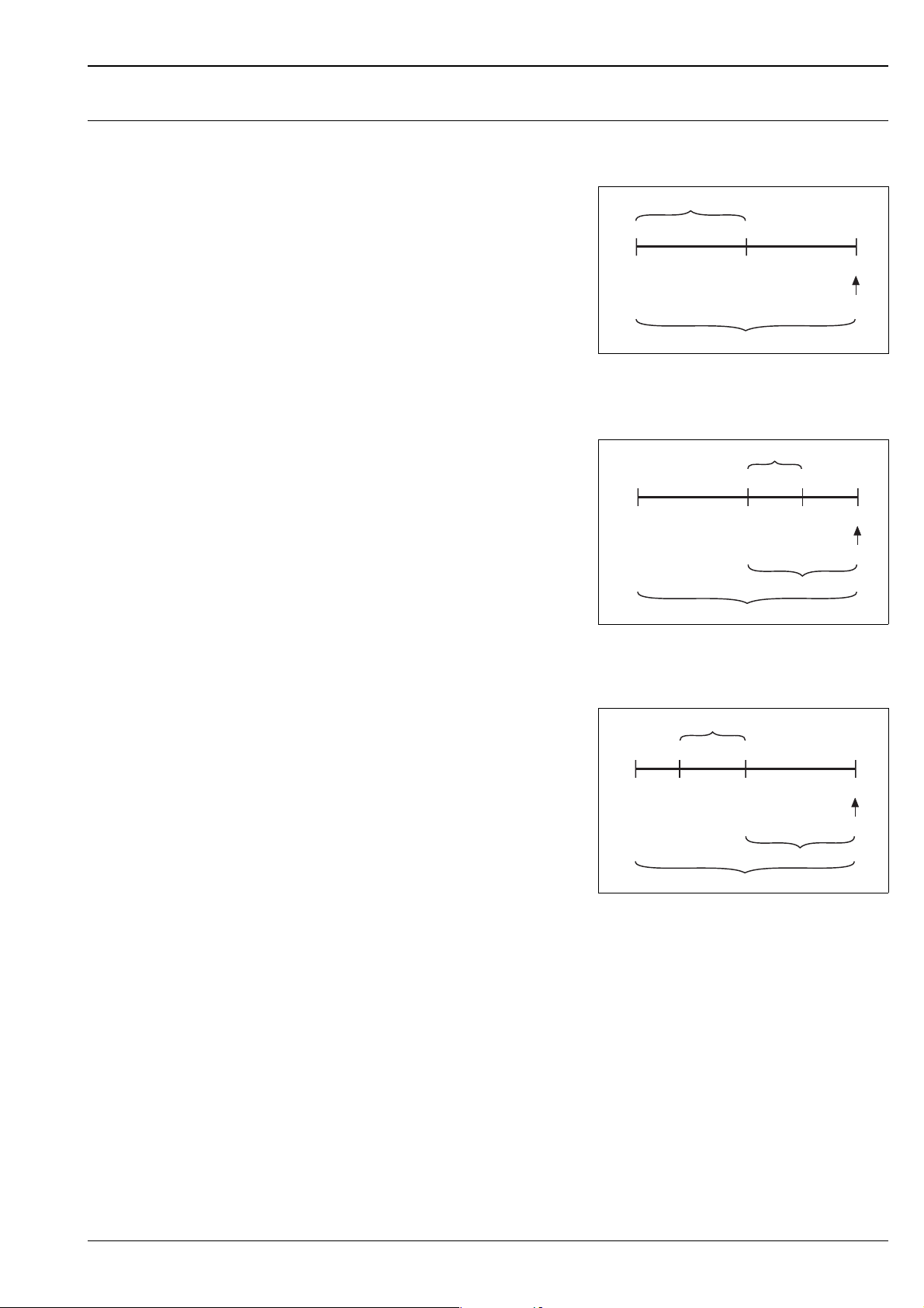
Explanation of terms: Turn down (TD),
set span and zero based span
Case 1:
• ⏐Upper range value⏐ ≤ ⏐Lower range value⏐
Example:
• Lower range value = 0 bar
• Upper range value = 0.5 bar
• Nominal value (URL) = 1 bar
Turn down:
• Nominal value /⏐Upper range value⏐= 1 bar/0.5 bar
TD = 2:1
set span:
• Upper range value – Lower range value = 0.5 bar – 0 bar
set span = 0.5 bar
This span is based on the zero point.
Case 2:
• ⏐Lower range value⏐ ≤ ⏐Upper range value⏐
Example:
• Lower range value (LRV) = 0 bar
• Upper range value (URV) = –0.5 bar
• Nominal value (URL) = 1 bar
Turn down:
• Nominal value /⏐Lower range value (LRV)⏐ =
1 bar/0.5 bar
TD = 2:1
set span:
• Upper range value – Lower range value = 0.5 bar – 0 bar
set span = 0.5 bar
This span is based on the zero point.
=
➁➀
LRL = LRV
0 bar
0.5 bar
➃
Example: 1 bar measuring cell
LRL
–1 bar
Example: 1 bar measuring cell
=
LRV
0
➄
➄
P01-PMx7xxxx-05-xx-xx-xx-012
=
➁➀
0.5 bar
➃
P01-PMx7xxxx-05-xx-xx-xx-007
URLURV
+1 bar
➂
URLURV
+1 bar
➂
Case 3:
• ⏐Lower range value⏐ ≥ ⏐Upper range value⏐
Example:
• Lower range value (LRV) = –0.6 bar
• Upper range value (URV) = 0 bar
• Nominal value (URL) = 1 bar
Turn down:
• Nominal value /⏐Lower range value (LRV)⏐ =
1 bar/0.6 bar
TD = 1.67:1
set span:
• Upper range value – Lower range value =
0 bar – (–0,6 bar)
set span = 0.6 bar
This span is based on the zero point.
=
➁➀
LRV
LRL
–1 bar
–0.6 bar
0
➃
➄
Example: 1 bar measuring cell
1Set span
2 Zero based span
3 Nominal value i Upper range limit (URL)
4 Nominal measuring range
5 Sensor measuring range
LRL Lower range limit
URL Upper range limit
LRV Lower range value
URV Upper range value
P01-PMx7xxxx-05-xx-xx-xx-008
URLURV
+1 bar
➂
Endress+Hauser 15
Page 16
Output
Output signal • 4...20 mA with superimposed digital communication protocol HART 5.0, 2-wire
• Digital communication signal PROFIBUS PA (Profile 3.0)
• Digital communication signal FOUNDATION Fieldbus
Cerabar S
Signal range –
3.8 mA to 20.5 mA
4...20 mA HART
Signal on alarm • 4...20 mA HART
Options:
– Max. alarm*: can be set from 21...23 mA
– Keep measured value: last measured value is kept
– Min. alarm: 3.6 mA
* Factory setting: 22 mA
• PROFIBUS PA: can be set in the Analog Input block,
options: Last Valid Out Value, Fsafe Value (factory setting), Status bad
• FOUNDATION Fieldbus: can be set,
options: Last good Value, Fail Safe Value (factory setting), Wrong Value
Load – 4...20 mA HART
R
L
➀
max
[]Ω
1500
1282
847
413
R
L
max
U – 10.5 V
≤
23 mA
➂
➃
➁
R
L
max
TestTest
[]Ω
1456
1239
804
U – 11.5 V
R
≤
L
max
23 mA
➃
369
➂
30
U–11V
23 mA
➄
30
40 45
40 45
10.5
R
L
max
[]Ω
1478
1260
826
391
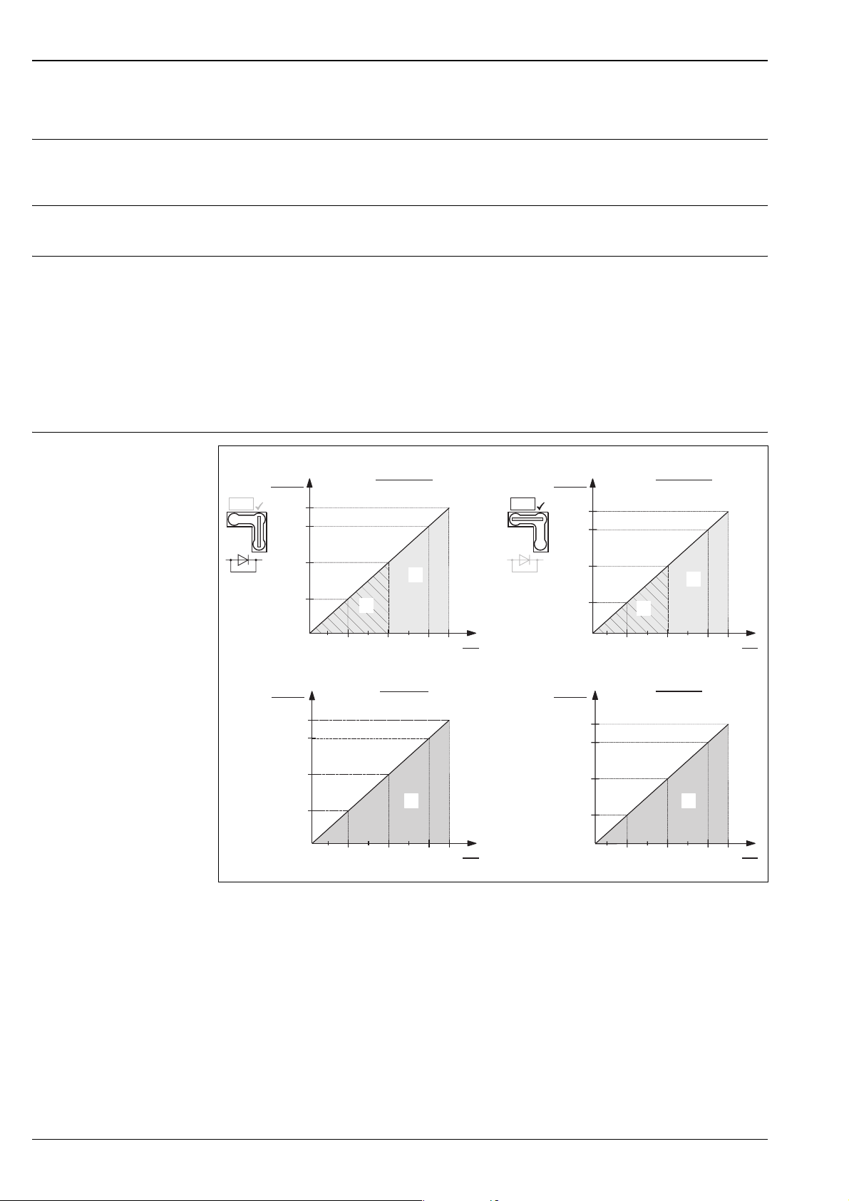
Load diagram, observe the position of the jumper and the explosion protection. (→ See also page 20, section "Taking
4...20 mA test signal" .)
1 Jumper for the 4...20 mA test signal inserted in "Non-test" position
2 Jumper for the 4...20 mA test signal inserted in "Test" position
3 Supply voltage 10.5 (11.5)...30 V DC for 1/2 G, 1 GD, 1/2 GD, FM IS, CSA IS, IECEx ia, NEPSI Ex ia and TIIS Ex ia
4 Supply voltage10.5 (11.5)...45 V DC for devices for non-hazardous areas, 1/2 D, 1/3 D, 2 G EEx d, 3 G EEx nA,
FM XP, FM DIP, FM NI, CSA XP, CSA Dust-Ex, NEPSI Ex d, TIIS Ex d
5 Supply voltage 11 (12)...45 V DC for PMC71, EEx d[ia], NEPSI Ex d[ia] and TIIS Ex d[ia]
R
Maximum load resistance
Lmax
U Supply voltage
20
R
≤
L
max
20
11
[V]
[V]
U
R
[]Ω
1434
1217
L
782
max
11.5
R
20
L
max
30
U–12V
≤
23 mA
40 45
➄
347
U
12
20
30
P01-PMx7xxxx-05-xx-xx-xx-003
40 45
[V]
[V]
U
U
Note!
When operating via a handheld terminal or via PC with an operating program, a minimum communication
resistance of 250 Ω must exist within the loop.
16 Endress+Hauser
Page 17

Cerabar S
Resolution • Current output: 1 µA
• Display: can be set (setting at the factory: presentation of the maximum accuracy of the transmitter)
Reading cycle • HART commands: on average 3 to 4 per second
• PROFIBUS PA:
– cyclic:
– max.: 100/s
– typical value: 20/s
– acyclic:
– max.: 20/s
– typical value: 10/s
• FOUNDATION Fieldbus:
– cyclic: up to 5/s, dependent on the number and type of function blocks used in a closed-control loop
– acyclic: 10/s
Cycle time (Update time) PROFIBUS PA
• The cycle time in a bus segment in cyclic data communication depends on the number of devices, on the
segment coupler used and on the internal PLC cycle time.
• The minimum cycle time is approx. 20 ms per device.
Response time • PROFIBUS PA:
– cyclic: approx. 10 ms per request
– acyclic: < 50 ms
• FOUNDATION Fieldbus:
– cyclic: < 80 ms
– acyclic: < 40 ms
All values are typical values.
Damping • Via on-site display, handheld terminal or PC with operating program, continuous from 0...999 s
• Additionally for HART and PROFIBUS PA: via DIP-switch on the electronic insert, switch position
"on" = set value and "off"
• Factory setting: 2 s
Endress+Hauser 17
Page 18
Power supply
Cerabar S
Electrical connection
4...20 mA HART
Note!
• When using the measuring device in hazardous areas, installation must comply with the corresponding
national standards and regulations and the Safety Instructions or Installation or Control Drawings. → See
also page 67 ff, sections "Safety Instructions" and "Installation/Control Drawings".
• Devices with integrated overvoltage protection must be earthed. → See also page 31.
• Protective circuits against reverse polarity, HF influences and overvoltage peaks are installed.
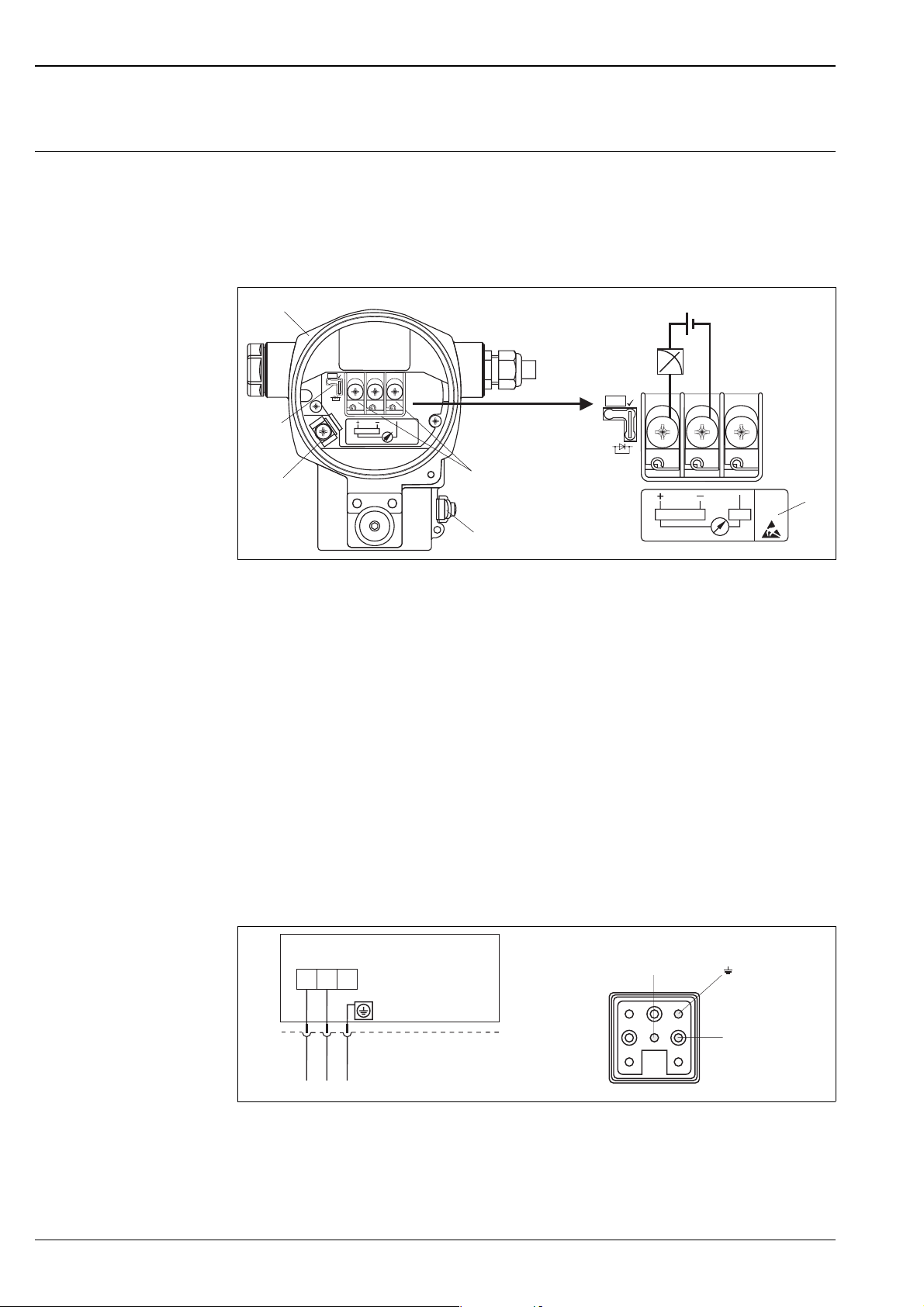
➀
➁
➂
Test
Test
4... 20mA
4…20 mA
Test
➄
4... 20mA
10.5 V DC
➅
11.5VDC
➆
Test
➇
➃
P01-xMx7xxxx-04-xx-xx-xx-001
Electrical connection 4...20 mA HART
1 Housing
2 Jumper for 4...20 mA test signal
→ See also page 20, section "Taking 4...20 mA test signal".
3 Internal earth terminal
4 External earth terminal
5 4...20 mA test signal between plus and test terminal
6 Minimum supply voltage 10.5 V DC, if the jumper is inserted in accordance with the illustration.
7 Minimum supply voltage 11.5 V DC, if the jumper is inserted in "Test" position.
8 Devices with integrated overvoltage protection are labelled OVP (overvoltage protection) here (→ see also page 31).
PROFIBUS PA
The two-wire cable must be connected to the "PA+" and "PA–" terminals.
FOUNDATION Fieldbus
The two-wire cable must be connected to the "FF+" and "FF–" terminals.
Devices with Harting plug Han7D
Cerabar S
+–
6
Han7D
+
–
Left: electrical connection for devices with Harting plug Han7D
Right: view of the plug at the device
5
+
7
8
1
2
3
4
–
P01-PMx7xxxx-04-xx-xx-xx-001
18 Endress+Hauser
Page 19
Cerabar S
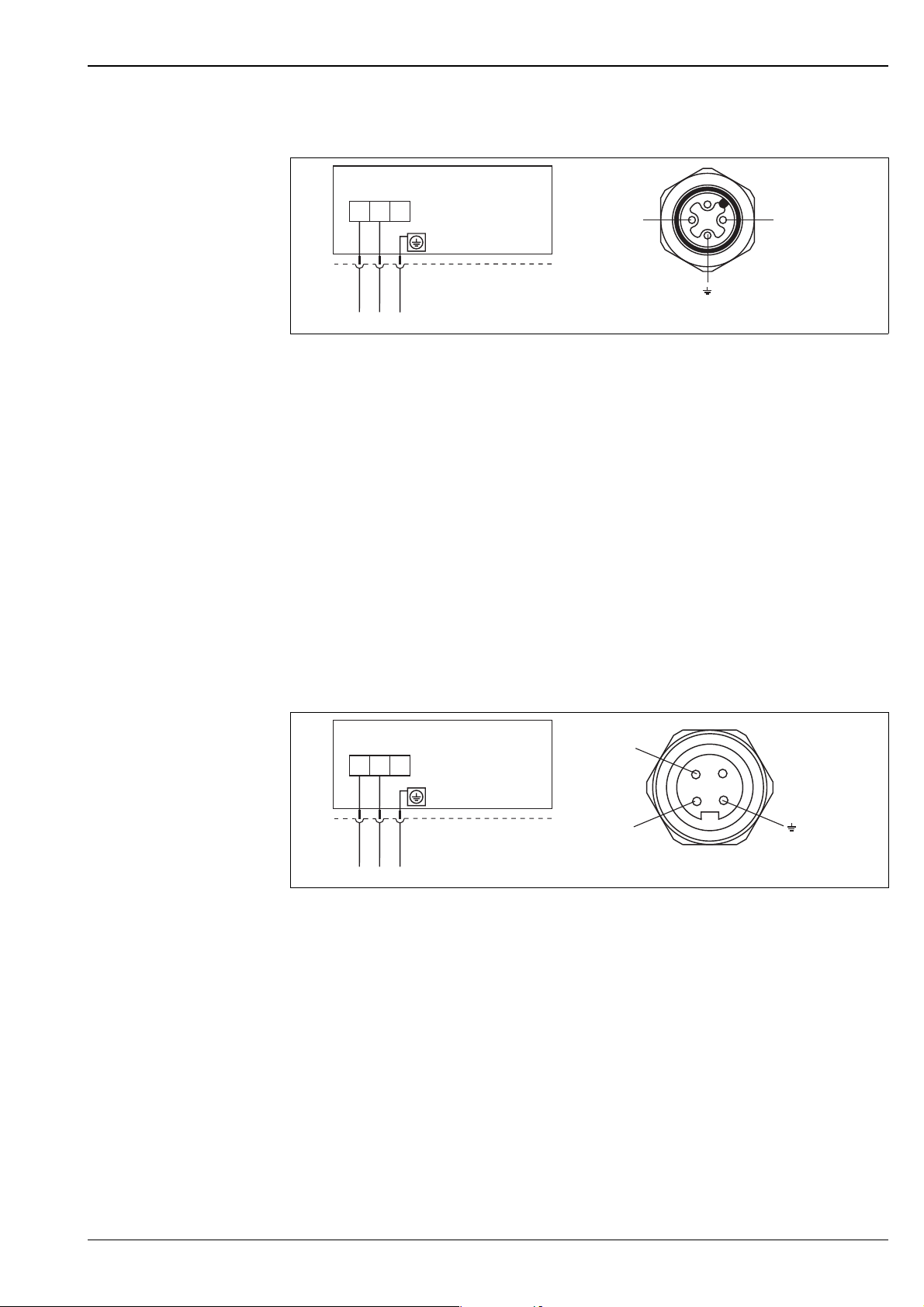
Devices with M12 plug
Cerabar S
+–
M12
+
–
Left: electrical connection for devices with M12 plug
Right: view of the plug at the device
Endress+Hauser offers for devices with M12 plug the following accessories:
Plug-in jack M 12x1, straight
• Material: Body PA; coupling nut CuZn, nickel-plated
• Degree of protection (fully locked): IP67
• Order number: 52006263
Plug-in jack M 12x1, elbowed
• Material: Body PBT/PA; coupling nut GD-Zn, nickel-plated
• Degree of protection (fully locked): IP67
• Order number: 51006327
2
Cable 4x0.34 mm
• Material: Body PUR; coupling nut CuSn/Ni; cable PVC
• Degree of protection (fully locked): IP67
• Order number: 52010285
with M12 socket, elbowed, screw plug, 5 m length
–
+
P01-PMx7xxxx-04-xx-xx-xx-000
Devices with 7/8" plug
Cerabar S
+–
7/8"
+
–
Left: electrical connection for devices with 7/8" plug
Right: view of the plug at the device
–
+
P01-PMx7xxxx-04-xx-xx-xx-003
Endress+Hauser 19
Page 20
Cerabar S
Test
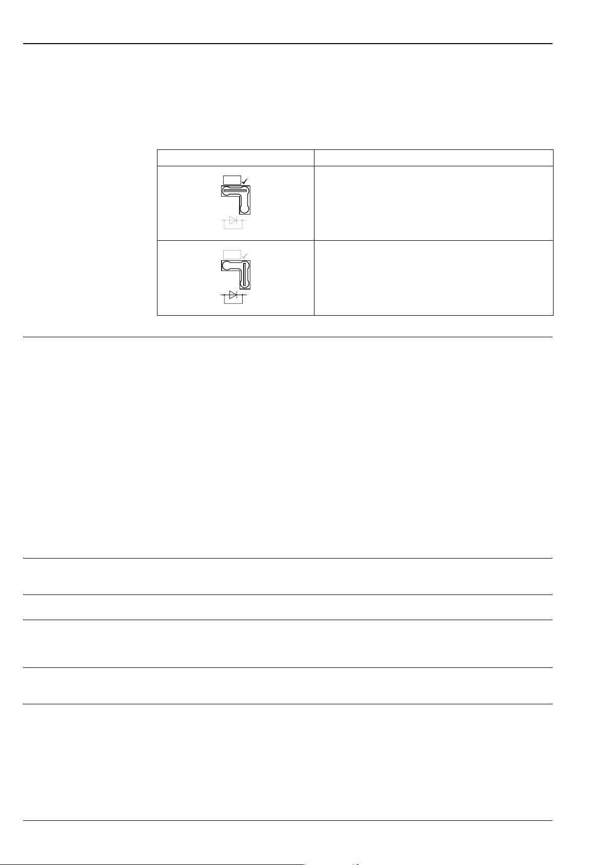
Taking 4...20 mA test signal
A 4...20 mA signal may be measured via the positive and test terminal without interrupting the measurement.
The minimum supply voltage of the device can be reduced by simply changing the position of the jumper. As
a result, operation is also possible with lower voltage sources. Observe the position of the jumper in accordance
with the following table.
Jumper position for test signal Description
Test
– Taking 4...20 mA test signal via plus and test terminal:
possible. (Thus, the output current can be measured without
interruption via the diode.)
– Delivery status
– minimum supply voltage: 11.5 V DC
Supply voltage Note!
• When using the measuring device in hazardous areas, installation must comply with the corresponding
national standards and regulations and the Safety Instructions or Installation or Control Drawings.
• All explosion protection data are given in separate documentation which is available upon request. The Ex
documentation is supplied as standard with all devices approved for use in explosion hazardous areas. → See
also page 82 ff sections "Safety Instructions" and "Installation/Control Drawings".
4...20 mA HART
• Version for non-hazardous areas, jumper for 4...20 mA test signal in "Test" position (delivery status):
11.5...45 V DC
• Version for non-hazardous areas, jumper for 4...20 mA test signal in "Non-test" position: 10.5...45 V DC
PROFIBUS PA
• Version for non-hazardous areas: 9...32 V DC
FOUNDATION Fieldbus
• Version for non-hazardous areas: 9...32 V DC
Test
– Taking 4...20 mA test signal via plus and test terminal:
not possible.
– minimum supply voltage: 10.5 V DC
Current consumption • PROFIBUS PA: 11 mA ± 1 mA, switch-on current corresponds to IEC 61158-2, Clause 21
• FOUNDATION Fieldbus: 14 mA ± 1 mA, switch-on current corresponds to IEC 61158-2, Clause 21
Cable entry → See also page 70 ff, feature 30 "Housing, Cable entry, Protection".
Cable specification • Endress+Hauser recommends using shielded, twisted-pair two-wire cables.
• Terminals for wire cross-sections 0.5...2.5 mm
2
• Cable external diameter: 5...9 mm
Residual ripple Without influence on 4...20 mA signal up to ± 5% residual ripple within the permitted voltage range [according
to HART hardware specification HCF_SPEC-54 (DIN IEC 60381-1)]
Influence of power supply ≤ 0.0006% of URL/1 V
20 Endress+Hauser
Page 21

Cerabar S
Performance characteristics – general
Reference operating conditions
• As per IEC 60770
• Ambient temperature T
• Humidity ϕ = constant, in the range of: 5...80 % r.H
• Ambient pressure pU = constant, in the range of: 860...1060 mbar
• Position of the measuring cell: constant, in the range of: ±1°
• Input of LOW SENSOR TRIM and HIGH SENSOR TRIM for lower range value and upper range value
• Zero based span
• Membrane material PMC71: Al
• Membrane material PMP71 and PMP75: AISI 316L/1.4435
• Filling oil: silicone oil
• Supply voltage: 24 V DC ± 3 V DC
• Load with HART: 250 Ω
Uncertainty of measurement for small absolute pressure ranges
The smallest extended uncertainty of measurement that can be returned by our standards is:
• 0.4% of the set span in the range of 1...30 mbar and
• 1% of the set span in the range < 1 mbar.
Long-term stability • ± 0.05% of URL/year
1) for measuring ranges ≥ 1 mbar
Influence of the installation position
• PMC71 1: ≤ 0.18 mbar
• PMP71
1, 2
– Process connections thread G 1 A, G 1 1/2, G 2, 1 1/2 MNPT, 2 MNPT, M 44x1.25, EN/DIN, ANSI
and JIS flanges: ≤ 10 mbar
– Process connections thread: G 1/2, 1/2 MNPT, JIS G 1/2, JIS R 1/2, M20x1.5: ≤ 4 mbar
= constant, in the range of: +21...+33°C (+69.8...+91.4°F)
U
(Aluminium oxide ceramic)
2O3
1
1) Device rotated 180°, process connection pointing upwards.
2) This value is doubled for devices with inert oil.
Position-dependent zero shift can be corrected. → See also page 27, section "General installation instructions"
and page 67 ff section "Installation instructions, Diaphragm seal systems".
Endress+Hauser 21
Page 22

Performance characteristics – ceramic diaphragm
Cerabar S
Reference accuracy – PMC71
The reference accuracy comprises the non-linearity including hysteresis and non-reproducibility in accordance
with the limit point method as per IEC 60770.
PMC71 – Gauge pressure sensors
100 mbar measuring cell:
• TD 1:1: to TD 10:1 ±0.075% of the set span
• TD > 10:1: ±0.0075% of the set span x TD
250 mbar, 400 mbar, 1bar, 2 bar, 4 bar, 10 bar measuring cell:
• TD 1:1: to TD 15:1 ±0.075% of the set span
• TD > 15:1: ±0.005% of the set span x TD
40 bar measuring cell:
• TD 1:1 to TD 10:1: ±0.075% of the set span
• TD > 10:1: ±0.0075% of the set span x TD
Platinum version,
1 bar, 2 bar, 4 bar, 10 bar measuring cell:
• TD 1:1: ±0.05% of the set span
PMC71 – Absolute pressure sensors
100 mbar measuring cell:
• TD 1:1: to TD 5:1: ±0.075% of the set span
• TD > 5:1: ±0.015% of the set span x TD
250 mbar measuring cell:
• TD 1:1: to TD 10:1: ±0.075% of the set span
• TD > 10:1: ±0.0075% of the set span x TD
400 mbar, 1 bar, 2 bar, 4 bar, 10 bar measuring cell:
• TD 1:1: to TD 15:1: ±0.075% of the set span
• TD > 15:1: ±0.005% of the set span x TD
40 bar measuring cell:
• TD 1:1 to TD 10:1: ±0.075% of the set span
• TD > 10:1: ±0.0075% of the set span x TD
Platinum version,
1 bar, 2 bar, 4 bar, 10 bar measuring cell:
• TD 1:1: ±0.05% of the set span
Total performance – PMC71
Warm-up period – PMC71
The "Total performance" specification comprises the non-linearity including hysteresis, non-reproducibility as
well as the thermal change of the zero point.
All specifications apply to the temperature range –10...+60°C (+14...+140°F).
PMC71
100 mbar, 250 mbar, 400 mbar measuring cell:
• ±0.2% of URL
1 bar, 2 bar, 4 bar, 10 bar, 40 bar measuring cell:
• ±0.15 % of URL
PMC71 High temperature version
all measuring cells:
• ±0.46% of URL
• 4...20 mA HART : < 10 s
• PROFIBUS PA: 6 s
• FOUNDATION Fieldbus: 50 s
22 Endress+Hauser
Page 23
Cerabar S
Dead time, Time constant (T63) – PMC71
Thermal change of the zero output and the output span – PMC71
I
100 %
63 %
t1t
2
Presentation of the dead time and the time constant
Type Dead time t
PMC71 90 ms 120 ms
1
Time constant (T63), t
2
t
PMC71
–10...+60°C (+14...+140 °F):
• 100 mbar, 250 mbar, 400 mbar measuring cell: ±(0.088 x TD + 0.088)% of the set span
• 1 bar, 2 bar, 4 bar, 10 bar, 40 bar measuring cell: ±(0.088 x TD + 0.04)% of the set span
–20...–10°C, +60...+125°C (–4...+14°F, +140...+257°F)
• 100 mbar, 250 mbar, 400 mbar, measuring cell: ±(0.138 x TD + 0.138)% of the set span
• 1 bar, 2 bar, 4 bar, 10 bar, 40 bar measuring cell: ±(0.175 x TD + 0.075)% of the set span
P01-xxxxxxxx-05-xx-xx-xx-007
PMC71 High temperature version
–10...+60°C (+14...+140 °F):
• 100 mbar, 250 mbar, 400 mbar measuring cell: ±(0.088 x TD + 0.088)% of the set span
• 1 bar, 2 bar, 4 bar, 10 bar, 40 bar measuring cell: ±(0.088 x TD + 0.04)% of the set span
–20...–10°C, +60...+150°C (–4...+14°F, +140...+302°F):
• all measuring cells: ±1.25% of URL x TD
Endress+Hauser 23
Page 24

Performance characteristics – metallic diaphragm
Cerabar S
Reference accuracy – PMP71, PMP75
The reference accuracy comprises the non-linearity including hysteresis and non-reproducibility in accordance
with the limit point method as per IEC 60770.
PMP71 and PMP75
100 mbar, 400 mbar measuring cell:
• TD 1:1: to TD 2:1 ±0.15% of the set span
250 mbar measuring cell:
• TD 1:1: to TD 2.5:1 ±0.15% of the set span
400 mbar measuring cell:
• TD 1:1: ±0.15% of the set span
• TD > 1:1: ±0.15% of the set span x TD
1 bar measuring cell:
• TD 1:1 to TD 2.5:1: ±0.075% of the set span
• TD > 2.5:1: ±0.03% of the set span x TD
2 bar measuring cell:
• TD 1:1 to TD 5:1: ±0.075% of the set span
• TD > 5:1: ±0.015% of the set span x TD
4 bar measuring cell:
• TD 1:1 to TD 10:1: ±0.075% of the set span
• TD > 10:1: ±0.0075% of the set span x TD
10 bar, 40 bar measuring cell:
• TD 1:1 to TD 15:1: ±0.075% of the set span
• TD > 15:1: ±0.005% of the set span x TD
100 bar measuring cell:
• TD 1:1 to TD 10:1: ±0.075% of the set span
• TD > 10:1: ±0.0075% of the set span x TD
400 bar measuring cell:
• TD 1:1 to TD 5:1: ±0.15% of the set span
• TD > 5:1: ±0.03% of the set span x TD
700 bar measuring cell:
• TD 1:1 to TD 2:1: ±0.2% of the set span
• TD > 2:1: ±0.1% of the set span x TD
Platinum version,
2 bar, 4bar, 10 bar, 40 bar measuring cell:
• TD 1:1: ±0.05% of the set span
24 Endress+Hauser
Page 25

Cerabar S
Total performance – PMP71
The "Total performance" specification comprises the non-linearity including hysteresis, non-reproducibility as
well as the thermal change of the zero point.
All specifications apply to the temperature range –10...+60°C (+14...+140°F).
PMP71
100 mbar measuring cell:
• ±0.35% of URL
250 mbar measuring cell:
• ±0.3% of URL
400 mbar measuring cell:
• ±0.25% of URL
1 bar, 2 bar, 4 bar, 10 bar, 40 bar measuring cell:
• ±0.15% of URL
100 bar measuring cell:
• ±0.25% of URL
400 bar measuring cell:
• ±0.3% of URL
700 bar measuring cell:
• ±0.4% of URL
PMP71 with Gold-Rhodium-coated membrane
400 mbar measuring cell:
• ±1.25% of URL
1 bar measuring cell:
• ±0.75% of URL
2 bar measuring cell:
• ±0.45% of URL
4 bar measuring cell:
•±0.3% of URL
10 bar and 40 bar measuring cell:
• ±0.15% of URL
100 bar measuring cell:
• ±0.25% of URL
400 bar measuring cell:
•±0.3% of URL
700 bar measuring cell:
•±0.4% of URL
Warm-up period – PMP71, PMP75
• 4...20 mA HART : < 10 s
• PROFIBUS PA: 6 s
• FOUNDATION Fieldbus: 50 s
Endress+Hauser 25
Page 26
Cerabar S
Dead time, Time constant (T63) – PMP71, PMP75
Thermal change of the zero output and the output span – PMP71
I
100 %
63 %
t1t
2
Presentation of the dead time and the time constant
Type Dead time t
PMP71 45 ms • 100 mbar, 250 mbar, 400 mbar measuring cell: 70 ms
PMP75 PMP71 + influence from the diaphragm seal
1
Time constant (T63), t
• measuring cells ≥ 1 bar: 35 ms
2
t
P01-xxxxxxxx-05-xx-xx-xx-007
PMP71
–10...+60°C (+14...+140°F):
• 100 mbar measuring cell: ±(0.3 x TD + 0.02)% of the set span
• 250 mbar measuring cell: ±(0.25 x TD + 0.02)% of the set span
• 400 mbar measuring cell: ±(0.2 x TD + 0.015)% of the set span
• 1 bar, 2 bar, 4 bar, 10 bar, 40 bar measuring cell: ±(0.1 x TD + 0.01)% of the set span
• 100 bar measuring cell: ±(0.2 x TD + 0.015)% of the set span
• 400 bar measuring cell: ±(0.35 x TD + 0.02)% of the set span
• 700 bar measuring cell: ±(0.4 x TD + 0.03)% of the set span
–40...–10°C, +60...+85°C (–40...+14°F, +140...+185°F):
• 100 mbar measuring cell: ±(0.6 x TD + 0.04)% of the set span
• 250 mbar measuring cell: ±(0.5 x TD + 0.04)% of the set span
• 400 mbar measuring cell: ±(0.4 x TD + 0.03)% of the set span
• 1 bar, 2 bar, 4 bar, 10 bar, 40 bar measuring cell: ±(0.4 x TD + 0.02)% of the set span
• 100 bar measuring cell: ±(0.4 x TD + 0.03)% of the set span
• 400 bar measuring cell: ±(0.7 x TD + 0.04)% of the set span
• 700 bar measuring cell: ±(0.75 x TD + 0.06)% of the set span
26 Endress+Hauser
Page 27
Cerabar S
Operating conditions (installation)
General installation instructions
Installation instructions for devices without diaphragm seal – PMC71 and PMP71
• For PMP75: See page 52 ff, "Installation instructions, Diaphragm seal systems" section.
• The position-dependent zero shift can be corrected directly at the device via operating key, for devices with
external operation even in hazardous areas. Diaphragm seals also shift the zero point, depending on the
installation position
(→ See also page 67 ff, section "Installation instructions, Diaphragm seal systems").
• The housing of the Cerabar S can be rotated up to 380°. → See also page 29, section "Turn the housing".
• Endress+Hauser offers a mounting bracket for installing on pipes or walls. → See also page 28, section "Wall
and pipe-mounting".
Cerabar S transmitters without diaphragm seal are mounted as per the norms for a manometer (DIN EN 839-
2). We recommend the use of shut-off devices and siphons. The orientation depends on the measuring
application.
Pressure measurement in gases
• Mount Cerabar S with shut-off device above the tapping point so that the condensate can flow into the
process.
Pressure measurement in steams
• Mount Cerabar S with siphon below the tapping point.
The siphon reduces the temperature to almost ambient temperature.
• Fill the siphon with fill fluid before commissioning.
Pressure measurement in liquids
• Mount Cerabar S with shut-off device below or at the same level as the tapping point.
Heat insulation – PMC71 high temperature version and PMP75
Level measurement
• Mount Cerabar S below the lowest measuring point.
• Do not mount the device at the following positions:
In the fill flow, in the tank outlet or at a point in the container which could be affected by pressure pulses
from the agitator.
• The calibration and functional test can be carried out more easily if you mount the device after a shut-off
device.
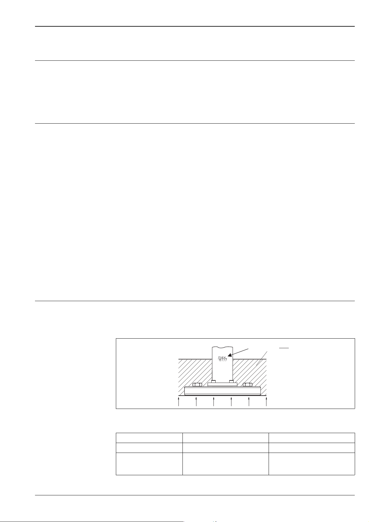
The PMC71 high temperature version and the PMP75 must only be insulated up to a certain height. The
maximum permitted insulation height is labelled on the devices and applies to an insulation material with a
heat conductivity ≤ 0.04 W/(m x K) and to the maximum permitted ambient and process temperature (→ see
table below). The data were determined under the most critical application "quiescent air".
W
λ 0.04≤
T
A
Maximum insulation height, here e.g. PMC71 with flange
mK•
T
P
P01-PMx7xxxx-11-xx-xx-xx-010
PMC71 high temperature version PMP75
Ambient temperature (TA) ≤ 70°C (158°F) ≤ 70°C (158°F)
Process temperature (T
) ≤ 150°C (302°F) max. 350°C (662°F), depending on the
P
diaphragm seal filling oil used (→ see
page 63)
Endress+Hauser 27
Page 28
Cerabar S
Mounting with temperature isolator
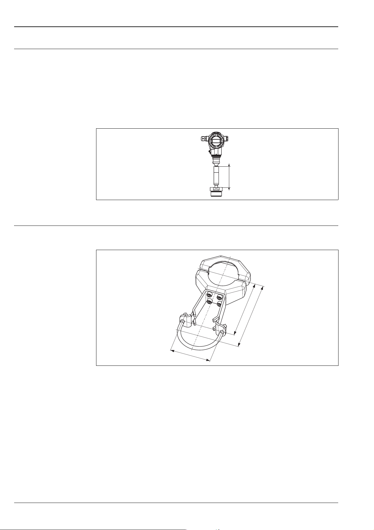
Endress+Hauser recommends the use of temperature isolators in the event of constant extreme fluid
temperatures which lead to the maximum permissible ambient temperature of +85°C (+185°F) being
exceeded.
Depending on the filling oil used, Cerabar S devices with temperature isolators can be used for maximum
temperatures of up to 260°C (+500°F). → For the temperature application limits of filling oils, see page 63,
"Diaphragm seal filling oil" section.
To minimise the influence of rising heat, Endress+Hauser recommends the device be mounted horizontally or
with the housing pointing downwards.
The additional installation height also brings about a zero point shift of maximum 21 mbar due to the
hydrostatic columns in the temperature isolator. The position-dependent zero shift can be corrected.
max. 115
P01-PMx7xxxx-11-xx-xx-xx-005
PMP75 with temperature isolator
Wall and pipe-mounting Endress+Hauser offers a mounting bracket for installing the device on pipes or walls. → See also page 70 ff,
feature 110, "Additional options 2".
70
101
118
P01-PMx7xxxx-06-xx-xx-xx-001
28 Endress+Hauser
Page 29
Cerabar S
FIELDTERMINALS
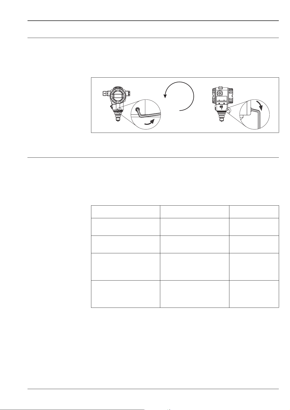
Turn the housing The housing can be rotated up to 380° by loosening the Allen screw.
Your benefits
• Simple mounting by optimally aligning the housing
• Good, accessible device operation
• Optimum readability of the on-site display (optional).
max. 380°
Align the housing by loosening the Allen screw.
T14 housing: 2 mm Allen key; T17 housing: 3 mm Allen key
FIELDTERMINALS
P01-PMx7xxxx-17-xx-xx-xx-000
Oxygen applications Oxygen and other gases can react explosively to oils, grease and plastics, such that, among other things, the
following precautions must be taken:
– All components of the system, such as measuring devices, must be cleaned in accordance with the BAM
(DIN 19247) requirements.
– Dependent on the materials used, a certain maximum temperature and a maximum pressure for oxygen
applications must not be exceeded.
The devices suitable for gaseous oxygen applications are listed in the following table with the specification p
Order code for devices cleaned for
oxygen applications
PMC71 – ********2**,
Devices with sensors,
nominal value < 10 bar
PMC71 – ********2**,
Devices with sensors,
nominal value ≥ 10 bar
PMP71 – *********N** Depends on the weakest link in terms of
PMP75 – **********N** Depends on the weakest link in terms of
p
for oxygen applications T
max
for oxygen
max
applications
Overpressure limit (OPL) of sensor
1, 2
60°C (140°F)
30 bar 60°C (140°F)
85°C (185°F)
pressure of the selected components: over
pressure limit (OPL) of sensor
1
or process
connection (1.5 x PN) or filling fluid
(160 bar)
85°C (185°F)
pressure of the selected components: over
pressure limit (OPL) of sensor
1
or process
connection (1.5 x PN) or filling fluid
(160 bar)
max
.
1) → See page 70 ff "Ordering information", feature 40 "Sensor range; sensor overload limit (= OPL)"
2) PMC71 with PVDF thread or flange p
= 15 bar (225 psi)
max
Endress+Hauser 29
Page 30

Ultra pure gas applications Endress+Hauser also offers the degreased device for special applications, such as ultra pure gas.
No special restrictions regarding the process conditions apply to this device.
→ See also page 72, "Ordering information PMC71", feature 80 "Seal" or page 76, "Ordering information
PMP71", feature 90 "Fill fluid".
Cerabar S
Diaphragm seals for materials
with hydrogen build-up (GoldRhodium coating)
With regard to materials in which hydrogen build-up takes place, hydrogen atoms can diffuse through the metal
diaphragms. This can result in incorrect measurement results.
Endress+Hauser offers diaphragms with Gold-Rhodium coating for this application.
→ See also page 75 "Ordering information PMP71" and page 79 "Ordering information PMP75", feature 60
"Membrane material" version "6".
Operating conditions (environment)
Ambient temperature limits • PMC71:
– –20...+85°C (–4...+185°F)
– High temperature version: –20...+70°C (–4...+158°F)
(Version "T" for feature 100 "Additional options 1" or feature 110 "Additional options 2"),
→ For the maximum insulation height see page 28.
• PMP71: –40...+85°C (–40...+185°F)
devices for lower temperatures on request
• PMP75: –40...+85°C (–40...+185°F)
devices for lower temperatures on request
→ For the maximum insulation height see page 28.
• On-site display: –20...+70°C (–4...+158°F)
Extended temperature application range with restrictions in optical properties such as display speed and
contrast: –40...+85°C (–40...+185°F)
For devices for use in hazardous areas, see Safety instructions, Installation or Control Drawing. (→ See also
page 82, sections "Safety Instructions" and "Installation/Control Drawings".)
The device can be used in this temperature range. The values of the specification, such as thermal change, may
be exceeded. → See also DIN 16086.
Storage temperature range • –40...+100°C (–40...+212°F)
• On-site display: –40...+85°C (–40...+185°F)
Degree of protection • → See page 70 ff, feature 30 "Housing, Cable entry, Protection".
• Degree of protection IP 68 for T17 housing: 1.83 mH
Climate class Class 4K4H (air temperature: –20...55°C/–4...+131°F, relative humidity: 4...100%) fulfilled as per
DIN EN 60721-3-4 (condensation possible)
1) With PMC71, avoid condensate in the device (avoid moisture collecting in the device).
O for 24 h
2
30 Endress+Hauser
Page 31

Cerabar S
Vibration resistance
Device/Additional option Test standard Vibration resistance
1
PMC71
PMP71
2, 3
PMP75
with mounting bracket IEC 61298-3 guaranteed for
1) not for high temperature version with EEx d[ia], CSA XP or FM XP
2) with aluminium T14 housing only
3) For applications with high temperatures, either a PMP75 with a temperature isolator or a PMP75 with a capillary
can be used. If vibrations also occur in the application, Endress+Hauser recommends using a PMP75 with a
capillary. If a PMP75 with a temperature isolator is used, it must be mounted with a mounting bracket. (→ see also
page 28).
GL guaranteed for
3...25 Hz: ±16 mm;
25...100 Hz: 4 g
in all 3 planes
10...60 Hz: ±0.15 mm;
60...500 Hz: 2 g
in all 3 planes
Electromagnetic compatibility • Interference emission as per EN 61326 electrical device B, Interference immunity as per EN 61326 appendix
A (industrial use) and NAMUR EMC recommendation (NE 21).
• With increased interference immunity against electromagnetic fields as per EN 61000-4-3:
30 V/m with closed cover
1
• Maximum deviation: < 0.5% of span
• All EMC measurements were performed with a turn down (TD) = 2:1.
1) for devices with T14 housing
Overvoltage protection • Overvoltage protection:
– Nominal functioning DC voltage: 600 V
– Nominal discharge current: 10 kA
• Surge current check î = 20 kA as per DIN EN 60079-14: 8/20 µs satisfied
• Arrester AC current check I = 10 A satisfied
→ See also page 73 ff, feature 100 "Additional options 1" and feature 110 "Additional options 2", version "M
Overvoltage protection".
Note!
Devices with integrated overvoltage protection must be earthed.
Endress+Hauser 31
Page 32

Operating conditions (Process)
Process temperature limits Note!
For oxygen applications, observe page 29, section "Oxygen applications".
PMC71 (with ceramic measuring diaphragm)
• –40...+125°C (–40...+257°F)
• High temperature version: –20...+150°C (–4...+302°F)
→ See also page 73, feature 100 "Additional options 1", Version "T".
• Observe the temperature operating range of the seal. See also the following section "Temperature operating
range, seals".
Extreme jumps in temperature can result in temporary measuring errors. Temperature compensation takes effect after several
minutes. Internal temperature compensation is faster the smaller the temperature jump and the longer the time interval.
PMP71 (with metallic measuring diaphragm)
Description Temperature operating range
Process connections with internal diaphragm –40...+125°C (–40...+257°F)
Process connections with flush-mounted diaphragm,
G 1 A, G 1 1/2 A, G 2 A, 1 NPT, 1 1/2 NPT, 2 NPT,
M 44 x 1.25, EN/DIN, ANSI and JIS flanges
Process connections with flush-mounted diaphragm,
G 1/2 A, M 20
Cerabar S
–40...+100°C (–40...+212°F)
–20...+85°C (–4...+185°F)
Temperature operating range, seals
PMP75 (with metallic measuring diaphragm)
• depending on the diaphragm seal and filling oil up to +350°C (+662°F)
Observe the temperature application limits of the diaphragm seal oil. → See also page 63, section
"Diaphragm seal filling oils".
PMC71 (with ceramic measuring diaphragm)
Version for feature 80 in the
order code
A FKM Viton –20...+125°C/150°C
2
B
B EPDM –20...+125°C (–4...+257°F)
D Kalrez, Compound 4079 +5...+125°C/150°C
E Chemraz, Compound 505 –10...+125°C/150°C
2, 3
F
3
F
1 FKM Viton, degreased –10...+125°C (+14...+257°F)
2 FKM Viton, cleaned for oxygen service –10...+60 °C (+14...+140°F)
Seal Temperature operating range
1
(–4...+257°F/302°F)
EPDM (FDA 21CFR177.2600; 3A Class I;
USP Class VI)
HNBR (FDA 21CFR177.2600; 3A Class II;
KTW; AFNOR; BAM; USP Class VI)
NBR –20...+100°C (–4...+212°F)
–20...+125°C (–4...+257°F)
1
(+41...+257°F/302°F)
1
(14...+257°F/302°F)
–20...+125°C (–4...+257°F)
1) +150°C (+302°F): for high temperature version
→ See also page 73, feature 100 "Additional options 1" and feature 110 "Additional options 2", Version "T".
2) These seals are used for devices with 3A-approved process connections.
3) For devices with NBR or HNBR seals, the values for "Toatal Performance" (→ see page 22) and "Thermal change"
(→ see page 23) must be multiplied by the factor 3.
32 Endress+Hauser
Page 33

Cerabar S
Pressure specifications • The MWP (maximum working pressure) is specified on the nameplate. The maximum pressure for the
measuring device is dependent on the lowest-rated element with regard to pressure, see the following
sections for this:
– → page 13 ff, section "Measuring range"
– → chapter "Mechanical construction".
The MWP (maximum working pressure) is specified on the nameplate. This value refers to a reference
temperature of 20°C (68°F) or 100°F for ANSI flanges. Observe pressure-temperature dependency.
• The pressure values permitted at higher temperatures can be found in the following standards:
– EN 1092-1: 2001 Tab. 18
– ASME B 16.5a – 1998 Tab. 2-2.2 F316
– ASME B 16.5a – 1998 Tab. 2.3.8 N10276
– JIS B2238/2210
• The test pressure corresponds to the over pressure limit (OPL) of the device = MWP x 1.5
• The Pressure Equipment Directive (EC Directive 97/23/EC) uses the abbreviation "PS". The abbreviation
"PS" corresponds to the MWP (maximum working pressure) of the measuring device.
• In the case of sensor range and process connections where the OPL (Over pressure limit) of the pressure
connection is smaller than the nominal value of the sensor, the device is set at the factory, at the very
maximum, to the OPL value of the process connection. If you want to use the entire sensor range, select a
process connection with a higher OPL value (1.5 x PN; PN = MWP).
• In oxygen applications, the values for "p
applications" may not be exceeded.
1
2
.
max
and T
for oxygen applications" as per page 30, "Oxygen
max
1) With regard to its stability property, the material 1.4435 is identical to 1.4404 which is grouped under 13EO in
EN 1092-1 Tab. 18. the chemical composition of the two materials can be identical.
2) The equation does not apply for PMP71 and PMP75 with a 100 bar measuring cell.
Endress+Hauser 33
Page 34
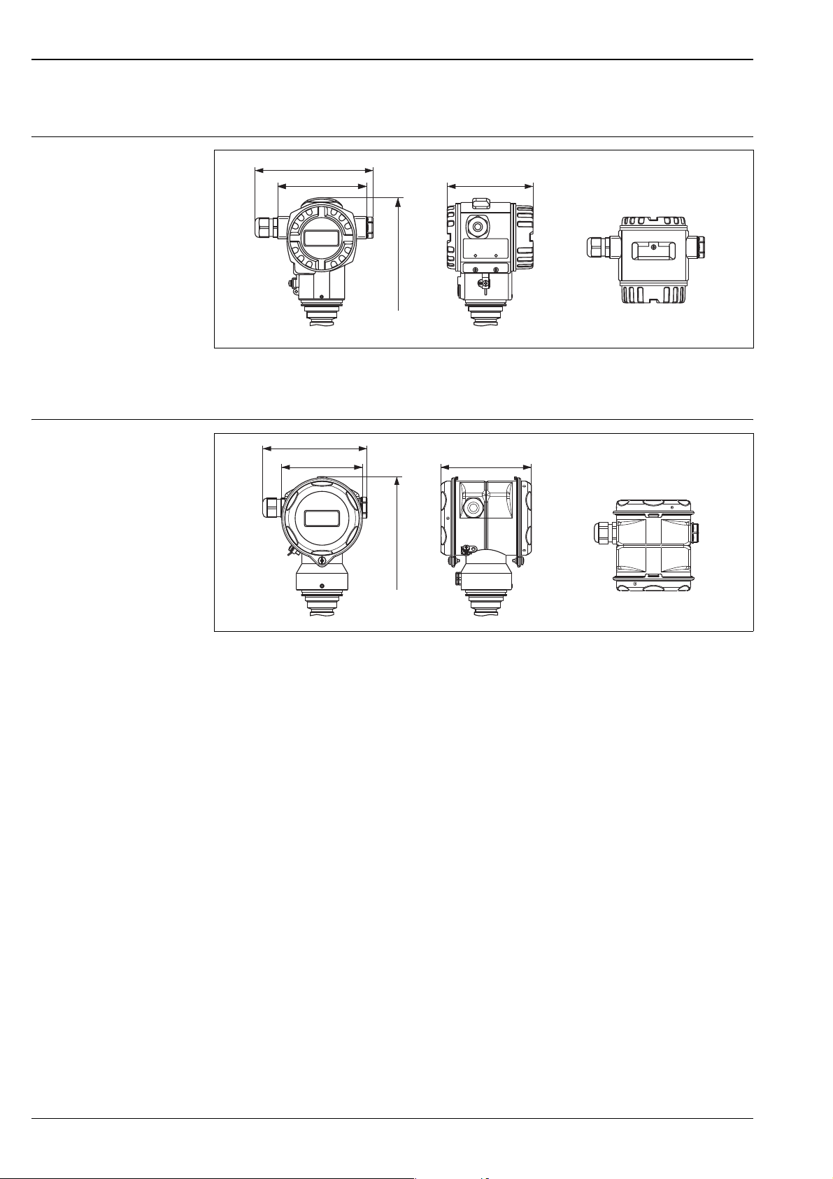
Mechanical construction
FIELDTERMINALS
FIELDTERMINALS
Cerabar S
Housing dimensions T14
Housing dimensions T17
152
111
111
FIELDTERMINALS
H
Front view, left-hand side view, top view
→ See the process connection in question for installation height. Housing weight see page 61.
132
152
102
111
FIELDTERMINALS
115
111
H
H
P01-PMx7xxx-06-00-xx-xx-000
Front view, left-hand side view, top view
→ See the process connection in question for installation height. Housing weight see page 61.
P01-PMx7xxxx-06-00-xx-xx-001
34 Endress+Hauser
Page 35
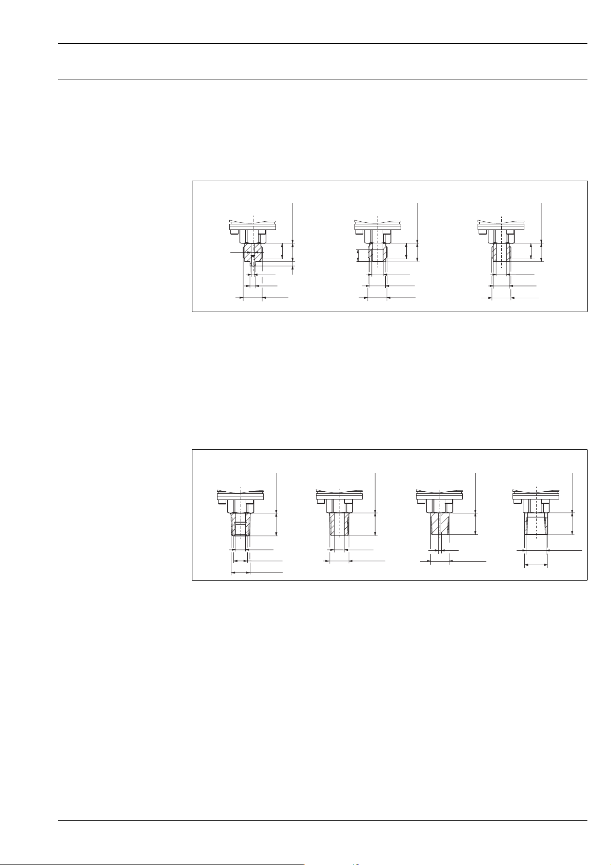
Cerabar S
Process connections PMC71 (with ceramic measuring diaphragm)
Note!
Some device versions have CRN approval. For a CRN-approved device, a CRN-approved process connection
(→ see page 72, feature 70 "Process connection") has to be ordered with a CSA approval (→ see page 70,
feature 10 "Approval"). These devices are fitted with a separate plate bearing the registration number
0F10525.5C.
Thread, internal diaphragm
G 1/2A
H
ø8
Process connections PMC71, thread ISO 228
→ Installation height see page 36.
1 Thread ISO 228 G 1/2 A EN 837;
Material version GA: AISI 316L/1.4435, version GB: Alloy C276/2.4819, version GC: Monel,
Version GD: PVDF (max.: 15 bar/225 psi, max.: –10...+60°C/+14...+140°F); mount version "GD" with a mounting
bracket only. (→ see also page 28)
2 Thread ISO 228 G 1/2 A G 1/4 (female);
Material version GE: AISI 316L/1.4435, version GF: Alloy C276/2.4819, version GG: Monel
3 Thread ISO 228 G 1/2 A hole 11.4 mm;
Material version GH: AISI 316L/1.4435, version GJ: Alloy C276/2.4819, version GK: Monel
ø3
ø6
G 1/2
17
20
3
G 1/2A G 1/4
13
G 1/4
ø17.5
G 1/2
17
H
20
G 1/2A 11.4 mm
➂➁➀
H
17
20
ø11.4
ø17.5
G 1/2
P01-PMC71xxx-06-09-xx-xx-001
➀➂➁➃
H
25
ø11.4
1/4 NPT
1/2 NPT
Process connections PMC71, thread ANSI
→ Installation height see page 36.
1 Thread ANSI 1/2 MNPT 1/4 FNPT;
Material version RA: AISI 316L/1.4435, version RB: Alloy C276/2.4819, version RC: Monel
2 Thread ANSI 1/2 MNPT hole 11.4;
Material version RD: AISI 316L/1.4435, version RE: Alloy C276/2.4819, version RF: Monel
3 Thread ANSI 1/2 MNPT hole 3 mm;
Material version RG: PVDF(max.: 15 bar/225 psi, max.: –10...+60°C/+14...+140°F),
mount with mounting bracket only (→ see also page 28)
4 Thread ANSI 1/2 FNPT;
Material version RH: AISI 316L/1.4435, version RJ: Alloy C276/2.4819, version RK: Monel
ø11.4
1/2 NPT
H
25
H
25
ø3
1/2 NPT
1/2 FNPT1/2 MNPT 3 mm1/2 MNPT 1/4 FNPT 1/2 MNPT 11.4 mm
H
25
1/2 NPT
ø26.5
P01-PMC71xxx-06-09-xx-xx-002
Endress+Hauser 35
Page 36
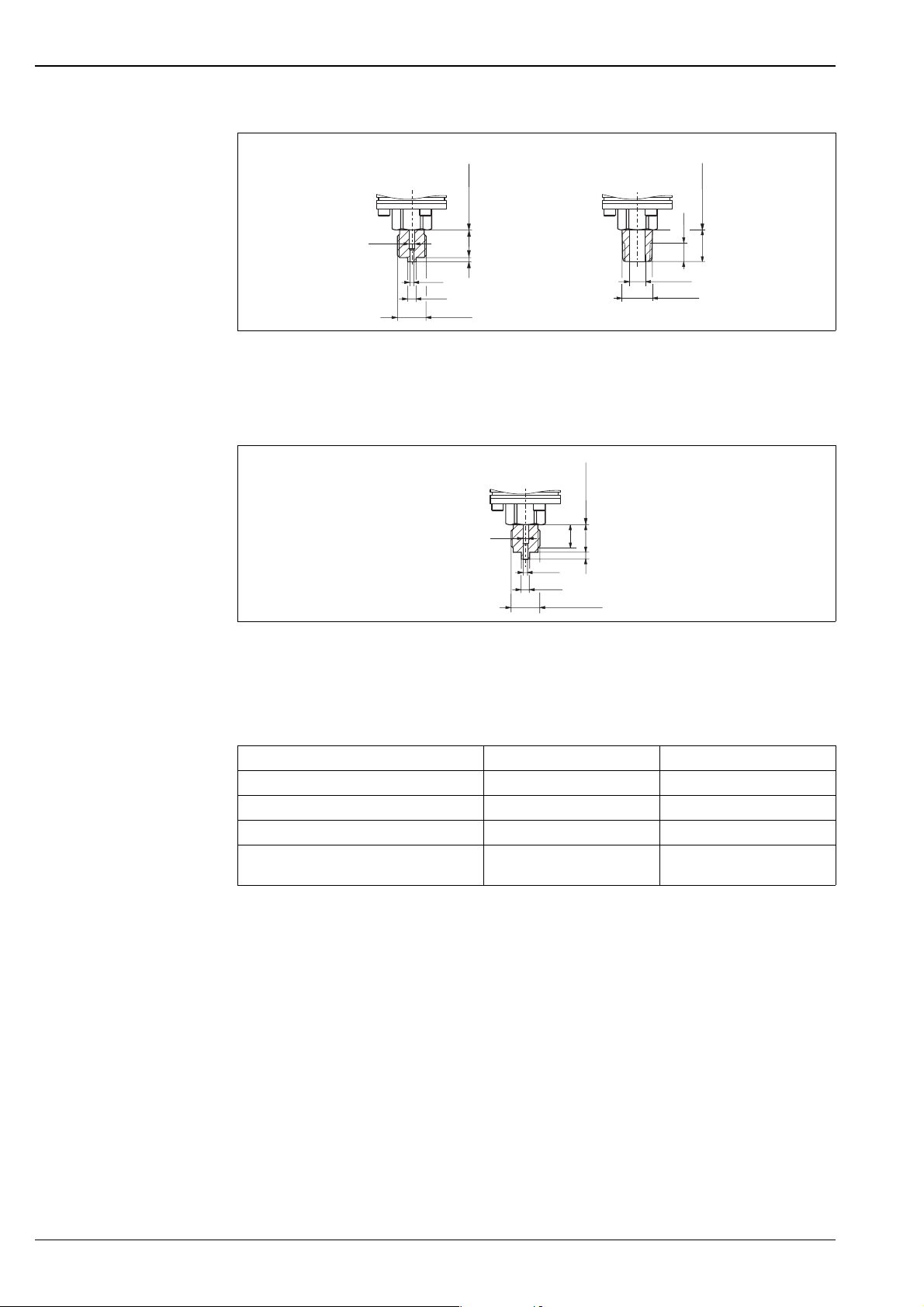
Cerabar S
G 1/2
➀
➁
HH
ø8
203
ø3
ø5
G 1/2
Process connections PMC71, thread JIS
→ Installation height see page 36.
1 Version GL: thread JIS B0202 G 1/2 (male), material: AISI 316L/1.4435
2 Version RL: thread JIS B0203 R 1/2 (male), material: AISI 316L/1.4435
M20x1.5
H
ø8
ø3
17
20
3
ø6
M20x1.5
Process connections PMC71 thread DIN 13 M 20x1.5 hole 3 mm
Material version GP: AISI 316L/1.4435, version GQ: Alloy C276/2.4819
→ Installation height see page 36.
R 1/2
H
13.2
23
ø11.4
R 1/2
P01-PMC71xxx-06-09-xx-xx-003
P01-PMC71xxx-06-09-xx-xx-004
Installation height H for devices with thread connection and internal diaphragm
Description Housing T14 Housing T17
PMC71 155 mm 171 mm
PMC71 with EEx d[ia], CSA XP or FM XP 236 mm 252 mm
PMC71 High temperature version
PMC 71 High temperature version
EEx d[ia], CSA XP or FM XP
1) High temperature version, see also page 73, feature 100 "Additional options 1" and
feature 110 "Additional options 2", versions "T"
1
1
with
235 mm 251 mm
300 mm 316 mm
36 Endress+Hauser
Page 37
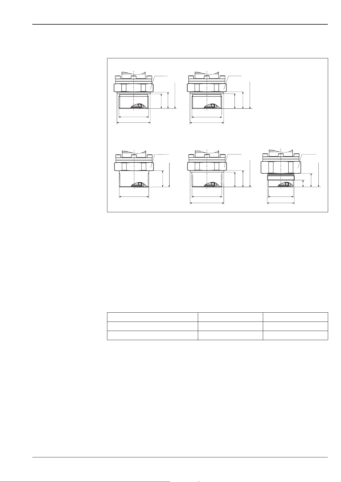
Cerabar S
Thread, flush-mounted diaphragm
G 1 1/2
➀
H
28
25
G 1 1/2
ø55
1 1/2 NPT
➂
H
27
1 1/2 NPT
Process connections PMC71,
→ Installation height see table below.
1 Thread ISO 228 G 1 1/2 A;
Material version 1G: AISI 316L/1.4435, version 1H: Alloy C276/2.4819, version 1J: Monel
2 Thread ISO 228 G 2 A;
Material version 1K: AISI 316L/1.4435, version 1L: Alloy C276/2.4819, version 1M: Monel
3 Thread ANSI 1 1/2 MNPT;
Material version 2D: AISI 316L/1.4435, version 2E: Alloy C276/2.4819, version 2F: Monel
4 Thread ANSI 2 MNPT;
Material version 2G: AISI 316L/1.4435, version 2H: Alloy C276/2.4819, version 2J: Monel
5 Thread DIN 13 M 44x1.25;
Material version 1R: AISI 316L/1.4435, version 1S: Alloy C276/2.4819
G2
➁
SW 60SW 60
60 AF60 AF
H
30
33.5
G2
ø68
2 NPT
➃➄
SW 60SW 60 SW 60
60 AF60 AF
H
30
33.5
2 NPT
ø68
M44x1.25
ø40.5
M44x1.25
60 AF
H
22
11
P01-PMC71xxx-06-09-xx-xx-005
Installation height H for devices with thread connection and flush-mounted diaphragm
Description Housing T14 Housing T17
PMC71 215 mm 231 mm
PMC71 with EEx d[ia], CSA XP or FM XP 280 mm 296 mm
Endress+Hauser 37
Page 38
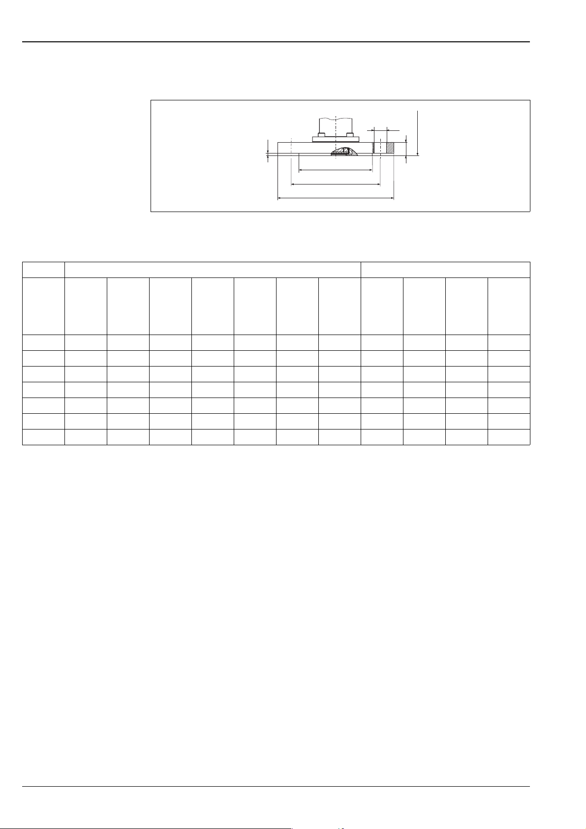
EN/DIN flanges, connection dimensions as per EN 1092-1/DIN 2527
g
2
H
2
g
k
D
Process connection PMC71, EN/DIN flange with raised face (flush-mounted diaphragm)
→ Installation height see page 40.
Flange Boltholes
Version Material Nominal
diameter
Nominal
pressure
Shape
1
Diameter Thick-
ness
Raised
face
Quantity Diameter Hole
Db g g2k
[mm] [mm] [mm] [mm] [mm] [kg]
CP AISI 316L
CQ AISI 316L
BR PVDF
3
DN 32 PN 10-40 B1 (D) 140 18 77 4 18 100 1.9
3
DN 40 PN 10-40 B1 (D) 150 18 87 4 18 110 2.2
4
DN 50 PN 10-16 B1 (D) 165 21.4 102 4 18 125 0.6
B3 AISI 316L 3DN 50 PN 10-40 B1 (D) 165 20 102 4 18 125 3.0
C3 AISI 316L
BS PVDF
3
DN 50 PN 63 B2 (D) 180 26 108 4 22 135 4.6
4
DN 80 PN 10/16 B1 (D) 200 21.4 138 8 18 160 1.0
B4 AISI 316L 3DN 80 PN 10-40 B1 (D) 200 24 138 8 18 160 5.4
b
P01-PMC71xxx-06-09-xx-xx-006
Flange
circle
weight
Cerabar S
2
1) Designation in brackets as per DIN 2527
2) Housing weight see page 61
3) AISI 316L/1.4435
4) Max.: 15 bar (225 psi), max.: –10...+60°C (+14...+140°F)
38 Endress+Hauser
Page 39
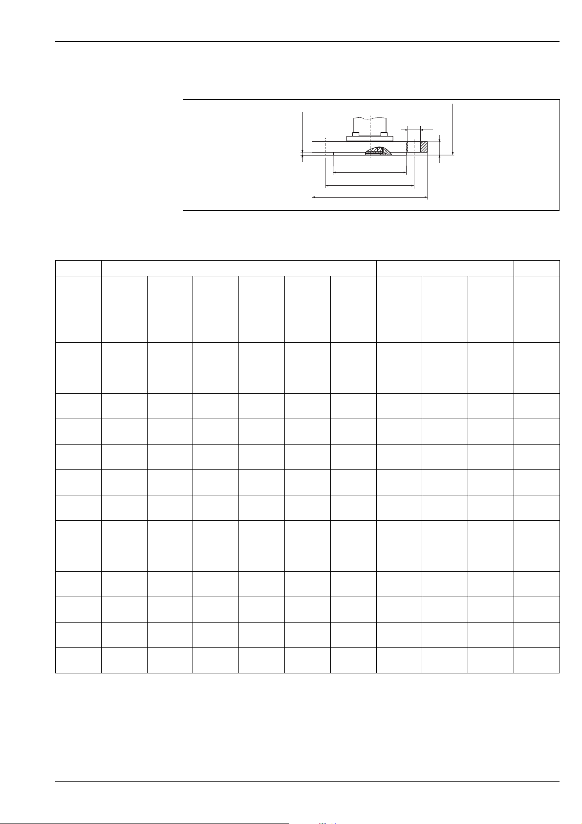
Cerabar S
Flange Boltholes
Version Material Nominal
AE AISI 316/
316L
AQ AISI 316/
316L
AF AISI 316/
316L
JR ECTFE
A3 PVDF
AR AISI 316/
316L
AG AISI 316/
316L
JS ECTFE
A4 PVDF
AS AISI 316/
316L
AH AISI 316/
316L
JT ECTFE
AT AISI 316/
316L
diameter
[in] [lb./sq.in] [in]
1 1/2 150 5
2
1 1/2 300 6.12
2
2 150 6
2
3
2 150 6
4
2 150 6
2 300 6.5
2
3 150 7.5
2
3
3 150 7.5
4
3 150 7.5
3 300 8.25
2
4 150 9
2
3
4 150 9
4 300 10
2
ANSI flange, connection dimensions as per ANSI B 16.5, raised face RF
g
2
[in]
[mm]
15.7
22.4
19.1
19.1
19.1
19.1
19.1
19.1
19.1
22.4
19.1
19.1
22.4
H
b
P01-PMC71xxx-06-09-xx-xx-007
[in]
[mm]
3.88
98.6
4.5
114.3
4.75
120.7
4.75
120.7
4.75
120.7
5
127
6
152.4
6
152.4
6
152.4
6.62
168.1
7.5
190.5
7.5
190.5
7.88
200.2
1.6
0.06
g
k
D
Process connection PMC71, ANSI flange with raised face (flush-mounted diaphragm)
→ Installation height see page 40.
Class Diameter Thickness Raised face Quantity Diameter Hole circle Flange
Db g g2k
[mm]
127
155.4
152.4
152.4
152.4
165.1
190.5
190.5
190.5
209.5
228.6
228.6
254
[in]
[mm]
0.69
17.5
0.81
20.6
0.75
19.1
0.75
19.1
0.75
19.1
0.88
22.4
0.94
23.9
0.94
23.9
0.94
23.9
1.12
28.4
0.94
23.9
0.94
23.9
1.25
31.8
[in]
[mm]
2.88
73.2
2.88
73.2
3.62
91.9
3.62
91.9
3.62
91.9
3.62
91.9
5
127
5
127
5
127
5
127
6.19
157.2
6.19
157.2
6.19
157.2
40.62
40.88
40.75
40.75
40.75
80.75
40.75
40.75
40.75
80.88
80.75
80.75
80.88
weight
[kg]
1.0
2.6
2.4
2.4
0.5
3.2
4.9
4.9
0.9
6.8
7.1
7.1
11.6
1
1) Housing weight see page 61
2) Combination of AISI 316 for required pressure resistance and AISI 316L for required chemical resistance (dual rated)
3) ECTFE coating on AISI 316L/1.4435
When operating in hazardous area, avoid electrostatic charge of the plastic surface.
4) max.: 15 bar (225 psi), max.: –10...+60°C (+14...+140°F)
Endress+Hauser 39
Page 40
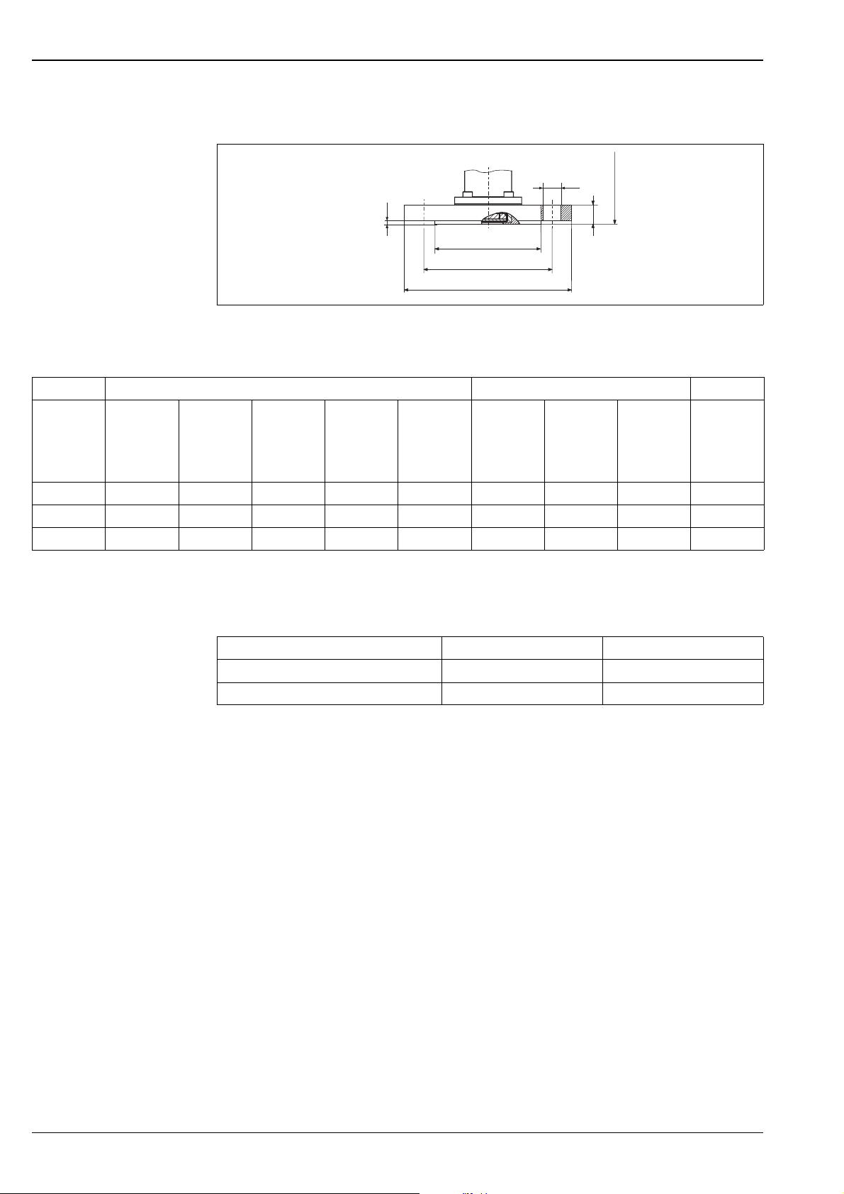
JIS flange, connection dimensions as per JIS B 2220, raised face RF
g
2
H
2
g
k
D
Process connection PMC71, JIS flange with raised face RF (flush-mounted diaphragm), AISI 316L/1.4435
→ Installation height see table below.
Flange Boltholes
Versions Nominal
dimension
Nominal
pressure
Diameter Thickness Raised face Quantity Diameter Hole circle Flange
Db g g2k
[mm] [mm] [mm] [mm] [mm] [kg]
KF 50 A 10 K 155 16 96 4 19 120 2.0
KL 80 A 10 K 185 18 127 8 19 150 3.3
KH 100 A 10 K 210 18 151 8 19 175 4.4
b
P01-PMC71xxx-06-09-xx-xx-008
weight
Cerabar S
1
1) Housing weight see page 61
Installation height H for devices with flange
Description T14 housing T17 housing
PMC71 215 mm 231 mm
PMC71 with EEx d[ia], CSA XP or FM XP 280 mm 296 mm
40 Endress+Hauser
Page 41
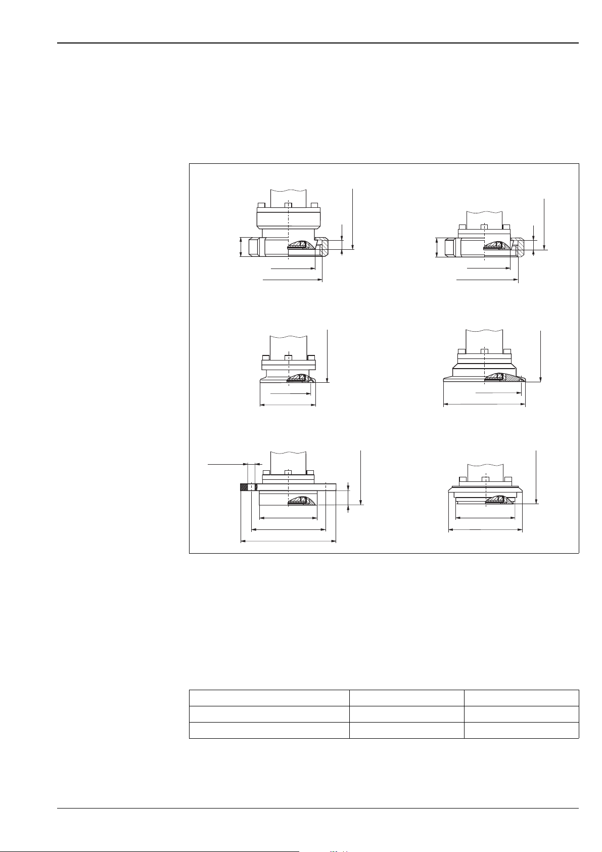
Cerabar S
Hygienic connections, flush-mounted diaphragm
Note!
Many process connections with an EPDM or HNBR seal are 3A-approved for PMC71. This means that a 3Aapproved process connection with an EPDM or HNBR seal must be selected when ordering for the 3A approval
for the PMC71 version to be valid. → For ordering information on EPDM or HNBR seals, see page 72 "Ordering
information PMC71", feature 80 "Sensor seal", version B or F.
DIN 11851 DN 40
➀
DIN 11851 DN 50
➁
21
ø48
Rd 65 x 1/6
Clamp ISO 2852 DN 51 (2")/
➂
DIN 32676 DN 50
10
H
22
ø61
Rd 78 x 1/6
Clamp ISO 2852 DN 76.1 (3")
➃
H
11
H
ø56.5
ø64
DRD 65 mm
➄
4xø11.5
ø65
ø84
ø105
Process connections PMC71, Hygienic connections, material AISI 316L/1.4435
surface roughness of the surfaces in contact with the medium ≤ 0.8 µm as standard. Lower surface roughness on request.
1 Version MP: DIN 11851 DN 40 PN 25, 3A with HNBR or EPDM seal
2 Version MR: DIN 11851 DN 50 PN 25, 3A with HNBR or EPDM seal
3 Version TD: Tri-Clamp ISO 2852 (2"), DIN 32675 DN 50, 3A with HNBR or EPDM seal
4 Version TF: Tri-Clamp ISO 2852 (3"), 3A with HNBR or EPDM seal
5 Version TK: DRD 65 mm PN 25, 3A with HNBR or EPDM seal
6 Version TR: Varivent Type N for pipes 40 – 162, PN 40, 3A with HNBR or EPDM seal
H
16
Varivent N DN 40 – DN 162
➅
83.5
ø91
ø68
ø84
H
H
P01-PMC71xxx-06-09-xx-xx-011
Installation height H for devices with hygienic connection and flush-mounted diaphragm
Description T14 housing T17 housing
PMC71 215 mm 231 mm
PMC71 with EEx d[ia], CSA XP or FM XP 280 mm 296 mm
Endress+Hauser 41
Page 42
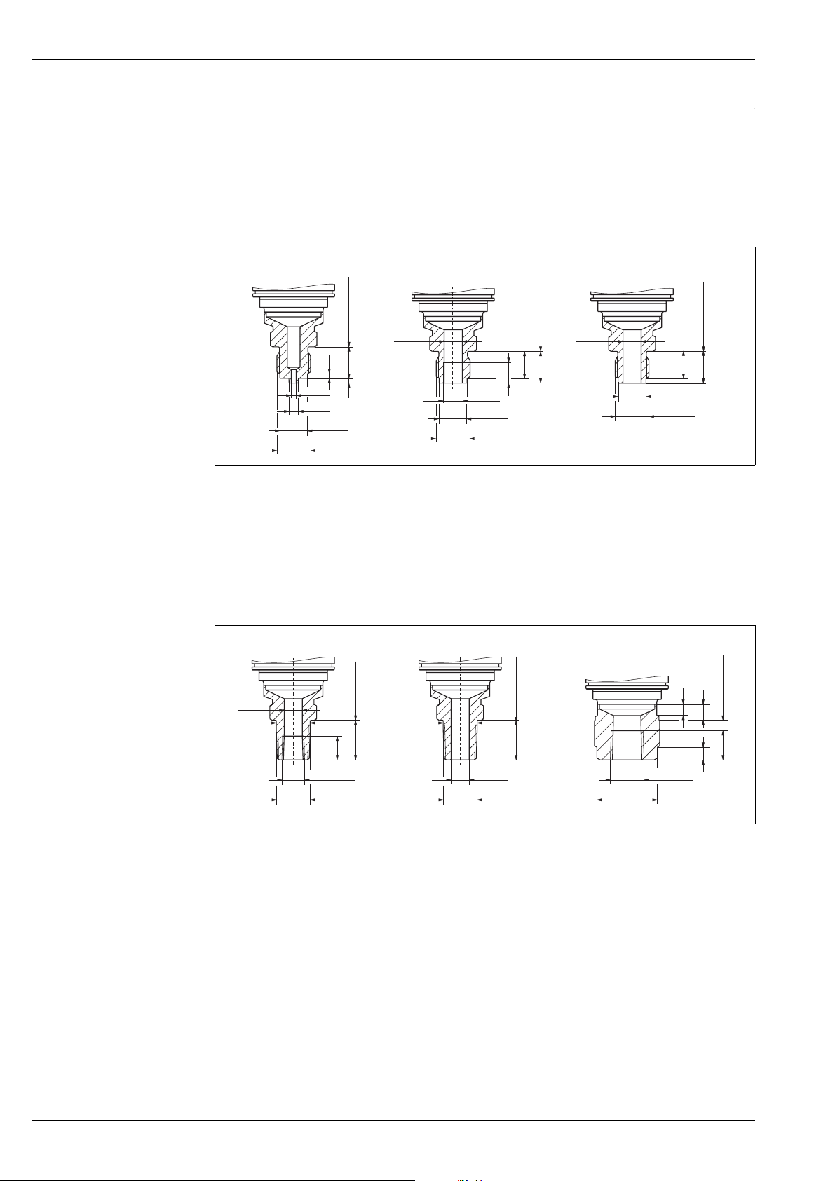
Cerabar S
Process connections PMP71 (with metallic measuring diaphragm)
Note!
Some device versions have CRN approval. For a CRN-approved device, a CRN-approved process connection
(→ see page 71, feature 70 "Process connection") has to be ordered with a CSA approval (→ see page 70,
feature 10 "Approval"). These devices are fitted with a separate plate bearing the registration number
0F10525.5C.
Thread, internal diaphragm
G 1/2A G 1/2A G 1/4 G 1/2A 11.4
➀➂➁
H
ø11.4 ø11.4
3
20
ø3.2
Process connections PMP71, thread ISO 228
→ Installation height H see page 43.
1 Thread ISO 228 G 1/2 A EN 837;
Material version GA: AISI 316L/1.4435, version GB: Alloy C276/2.4819
2 Thread ISO 228 G 1/2 A G 1/4 (female);
Material version GE: AISI 316L/1.4435, version GF: Alloy C276/2.4819
3 Thread ISO 228 G 1/2 A hole 11.4 mm;
Material version GH: AISI 316L/1.4435, version GJ: Alloy C276/2.4819
ø6
ø17.5
G 1/2 A
3
G 1/4
ø17.5
G 1/2 A
13
17
H
20
17
ø17.5
G 1/2 A
P01-PMP71xxx-06-09-xx-xx-000
H
20
1/2 MNPT 1/4 FNPT 1/2 MNPT 11.4 1/2 FNPT
➀➂➁
H
ø11.4
ø21.4
25
15
1/4 NPT
1/2 NPT
Process connections PMP71, thread ANSI
→ Installation height see page 43.
1 Thread ANSI 1/2 MNPT 1/4 FNPT;
Material version RA: AISI 316L/1.4435, version RB: Alloy C276/2.4819
2 Thread ANSI 1/2 MNPT hole 11.4;
Material version RD: AISI 316L/1.4435, version RE: Alloy C276/2.4819
3 Thread ANSI 1/2 FNPT;
Material version RH: AISI 316L/1.4435, version RJ: Alloy C276/2.4819
ø21.4
H
25
ø11.4
1/2 NPT
ø38
7
1/2 NPT
P01-PMP71xxx-06-09-xx-xx-001
10
8
H
20
42 Endress+Hauser
Page 43
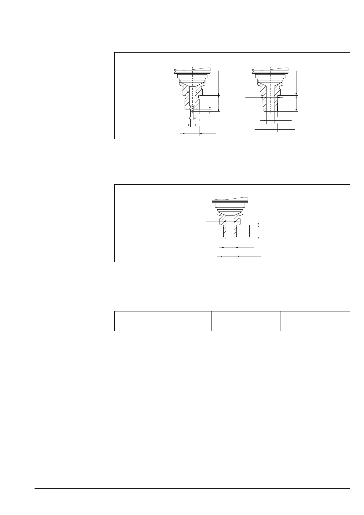
Cerabar S
G 1/2 R 1/2
➀➁
H
ø8
3
23
ø3
ø5
G 1/2
Process connections PMP71, thread JIS
→ Installation height H see table, below.
1 Version GL: thread JIS B0202 G 1/2 (male), material: AISI 316L/1.4435
2 Version RL: thread JIS B0203 R 1/2 (male), material: AISI 316L/1.4435
M 20x1.5
ø11.4
Process connections PMP71 thread DIN 13 M 20x1.5 hole 11.4 mm
Material version GP: AISI 316L/1.4435, version GQ: Alloy C276/2.4819
→ Installation height H see table, below.
ø21.4
17
ø17.5
M20x1.5
H
20
H
23
ø11.4
R 1/2
P01-PMP71xxx-06-09-xx-xx-002
P01-PMP71xxx-06-09-xx-xx-003
Installation height H for devices with thread connection and internal flush-mounted diaphragm
T14 housing T17 housing
Height H 165 mm 181 mm
Endress+Hauser 43
Page 44
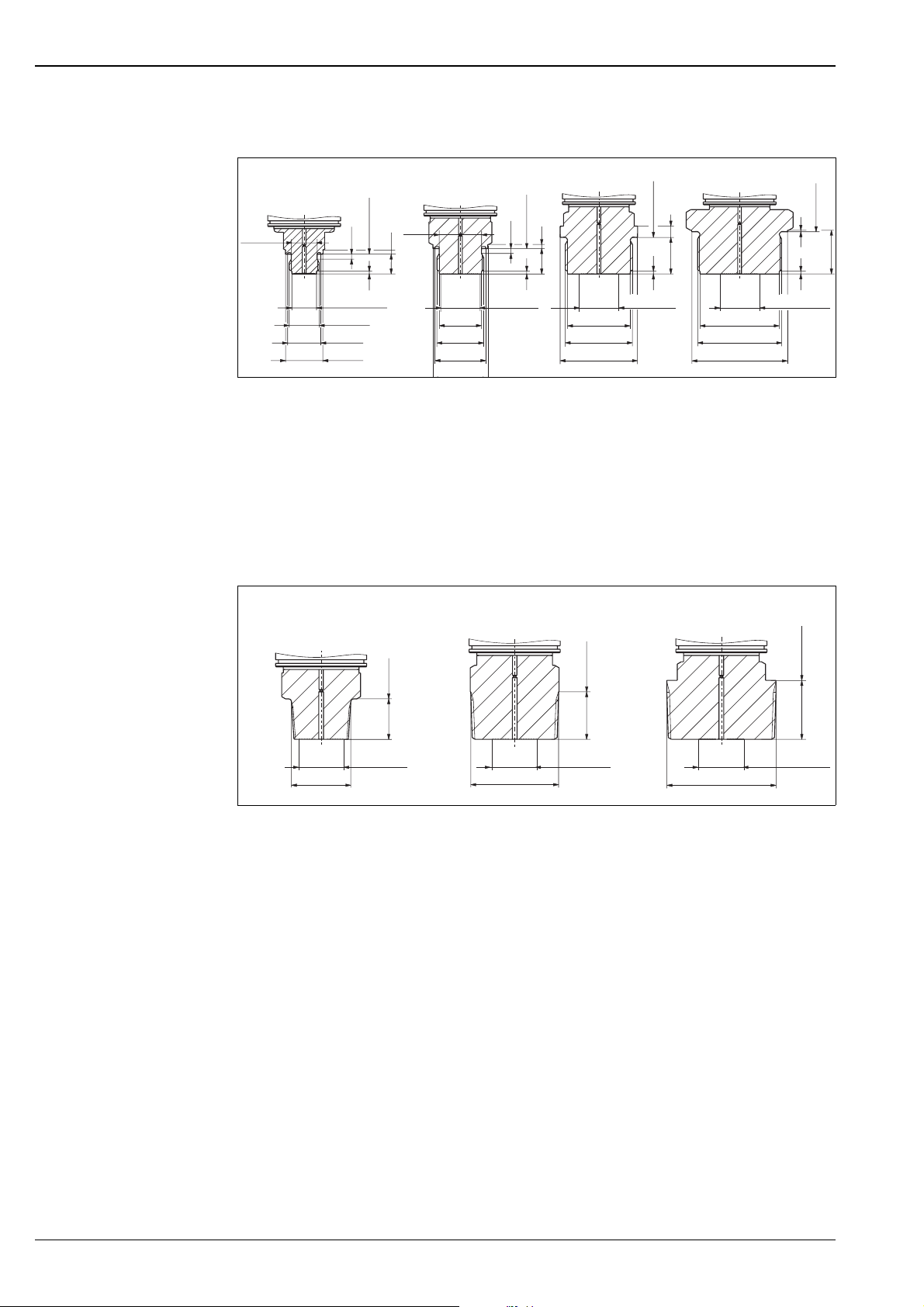
Cerabar S
Thread, flush-mounted diaphragm
G 1/2A G 1 1/2A G 2AG1A
➀➂➁➃
1
2
d=Mø28
H
31
H
ø30
ø18.4
d=
M
G 1/2A
ø23.6
ø26.5
Process connections PMP71, thread ISO 228
→ Installation height see page 45.
1 Thread ISO 228 G 1/2 A DIN 3852;
Material version 1A: AISI 316L/1.4435, version 1B: Alloy C276/2.4819
2 Thread ISO 228 G 1 A;
Material version 1D: AISI 316L/1.4435, version 1E: Alloy C276/2.4819
3 Thread ISO 228 G 1 1/2 A
Material version 1G: AISI 316L/1.4435, version 1H: Alloy C276/2.4819
4 Thread ISO 228 G 2 A
Material version 1K: AISI 316L/1.4435, version 1L: Alloy C276/2.4819
3.5
ø17.5
3
14
2
ø30
G1A
ø36
ø39
H
3.5
2
d=Mø28
3
18
ø36
G 1 1/2A
ø55
H
8
26
2
d=Mø28
ø56.3
G2A
ø68
P01-PMP71xxx-06-09-xx-xx-004
1 MNPT
➀➂➁
H
23
d=Mø28 d=Mø28 d=Mø28
1 NPT
Process connections PMP71, thread ANSI
→ Installation height see page 45.
1 Thread ANSI 1 MNPT;
Material version 2A: AISI 316L/1.4435, version 2B: Alloy C276/2.4819
2 Thread ANSI 1 1/2 MNPT;
Material version 2D: AISI 316L/1.4435, version 2E: Alloy C276/2.4819
3 Thread ANSI 2 MNPT
Material version 2G: AISI 316L/1.4435, version 2H: Alloy C276/2.4819
1 1/2 MNPT
1 1/2 NPT
H
27
2 MNPT
H
33.5
2 NPT
P=1-PMP71xxx-06-09-xx-xx-005
44 Endress+Hauser
Page 45
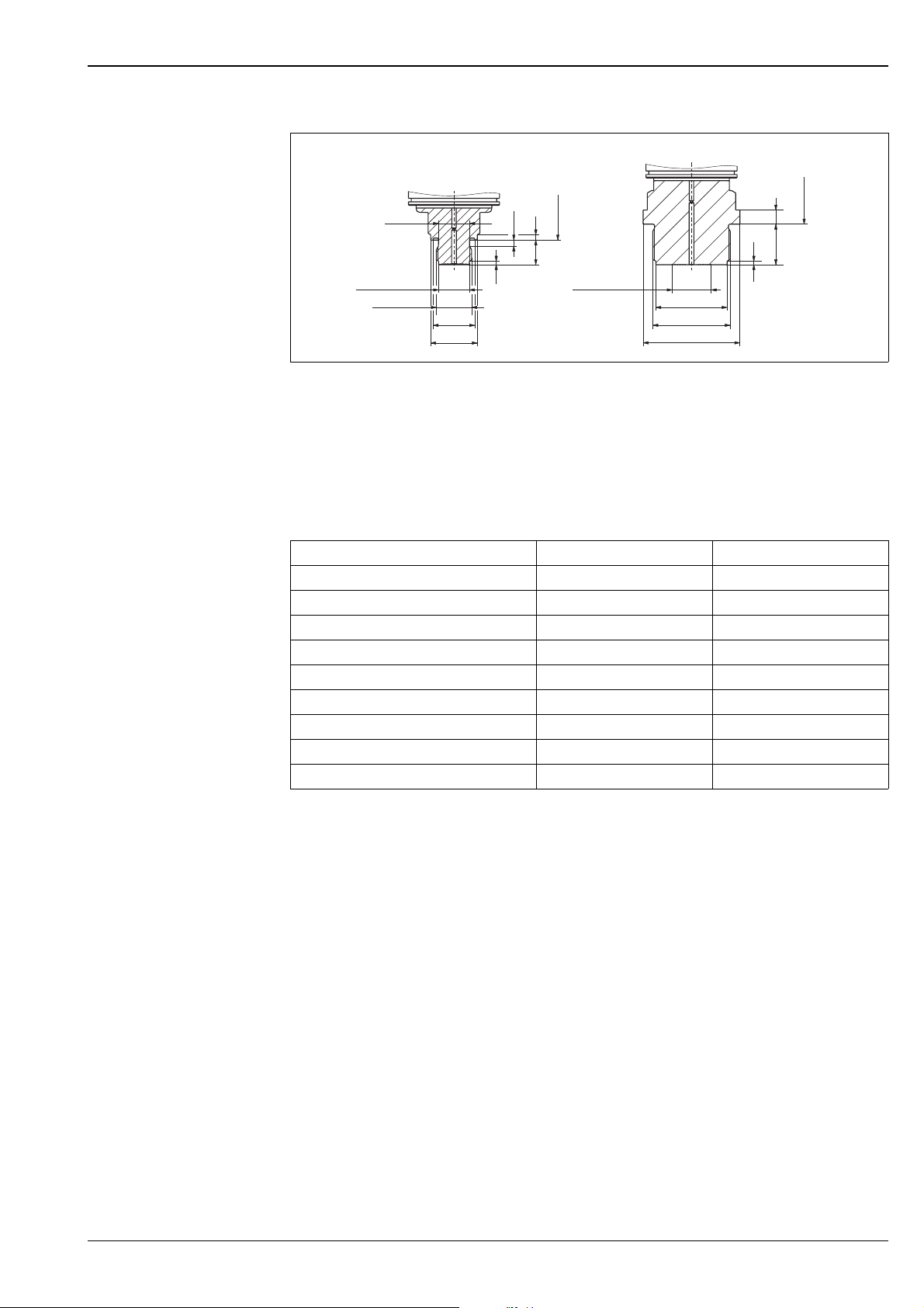
Cerabar S
M 20x1.5 M 44x1.25
➀➁
ø17.7
d=Mø17.5 d=Mø17.5
M20x1.5
ø23.6
ø26.5
Process connections PMP71, thread DIN
→ Installation height see table, below.
1 Thread DIN 16288 M20;
Material version 1N: AISI 316L/1.4435, version 1P: Alloy C276/2.4819
2 Thread DIN 13 M 44 x 1.25;
Material version 1R: AISI 316L/1.4435, version 1S: Alloy C276/2.4819
2
3.5
3
14
H
H
23 8
2
ø40.5
M44x1.25
ø55
P01-PMP71xxx-06-09-xx-xx-006
Installation height H for devices with thread connection and flush-mounted diaphragm
Description Housing T14 Housing T17
G 1/2 163 mm 179 mm
G 1 167 mm 183 mm
G 1 1/2 A 163 mm 179 mm
G 2 A 162 mm 178 mm
1 MNPT 162 mm 178 mm
1 1/2 MNPT 165 mm 181 mm
2 MNPT 159 mm 175 mm
M 20x1.5 163 mm 179 mm
M 44x1.25 170 mm 186 mm
Endress+Hauser 45
Page 46
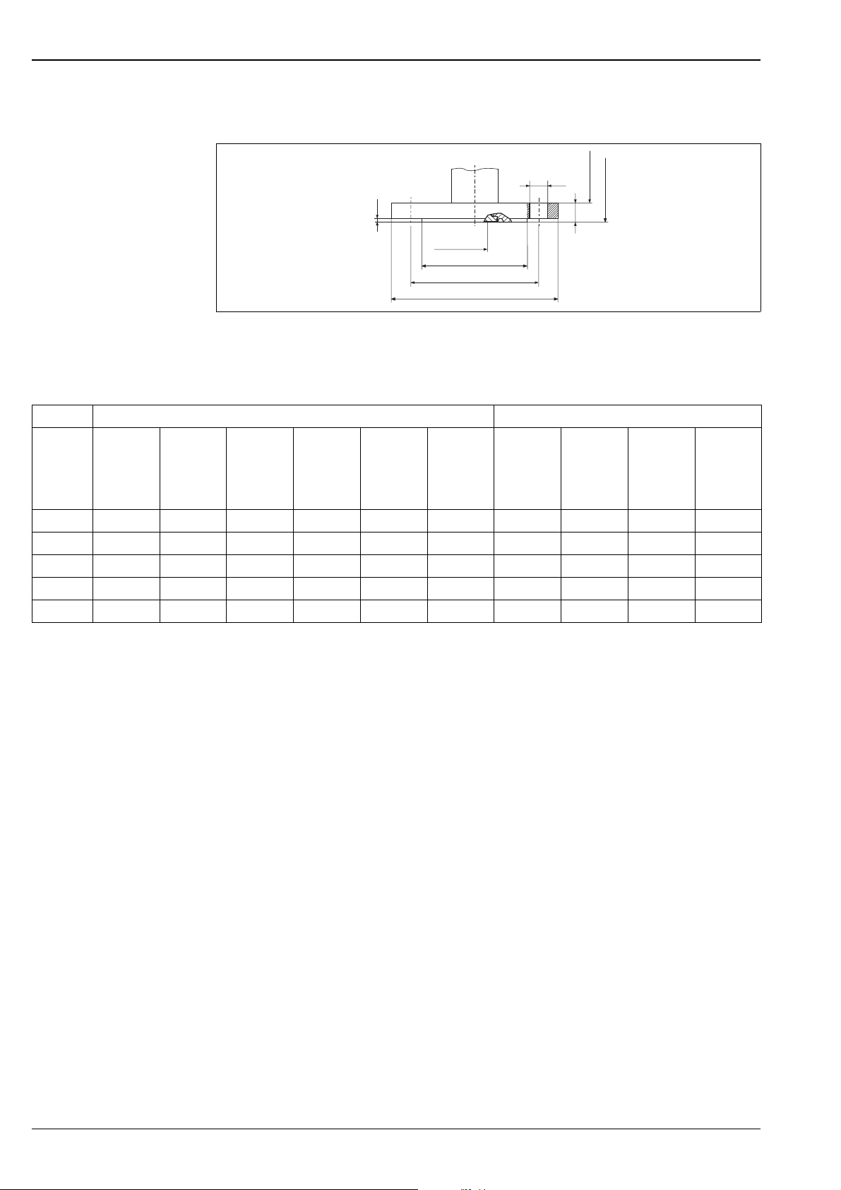
EN/DIN flanges, connection dimensions as per EN 1092-1/DIN 2527
h
g
2
Cerabar S
H
2
b
d=Mø28
g
k
D
P01-PMP71xxx-06-09-xx-xx-008
Process connection PMP71, EN/DIN flange with raised face, material AISI 316L/1.4435
H: device height = height of device without flange + flange thickness b
→ Height h see page 48.
Flange Boltholes
Version Nominal
diameter
Nominal
pressure
Shape
1
Diameter Thickness Raised face Quantity Diameter Hole circle Flange
weight
Db g g2k
[mm] [mm] [mm] [mm] [mm] [kg]
CN DN 25 PN 10-40 B1 (D) 115 18 66 4 14 85 1.2
CP DN 32 PN 10-40 B1 (D) 140 18 77 4 18 100 1.9
CQ DN 40 PN 10-40 B1 (D) 150 18 87 4 18 110 2.2
B3 DN 50 PN 10-40 B1 (D) 165 20 102 4 18 125 3.0
B4 DN 80 PN 10-40 B1 (D) 200 24 138 8 18 160 5.3
2
1) Designation as per DIN 2527 in brackets
2) Housing weight see page 61
46 Endress+Hauser
Page 47
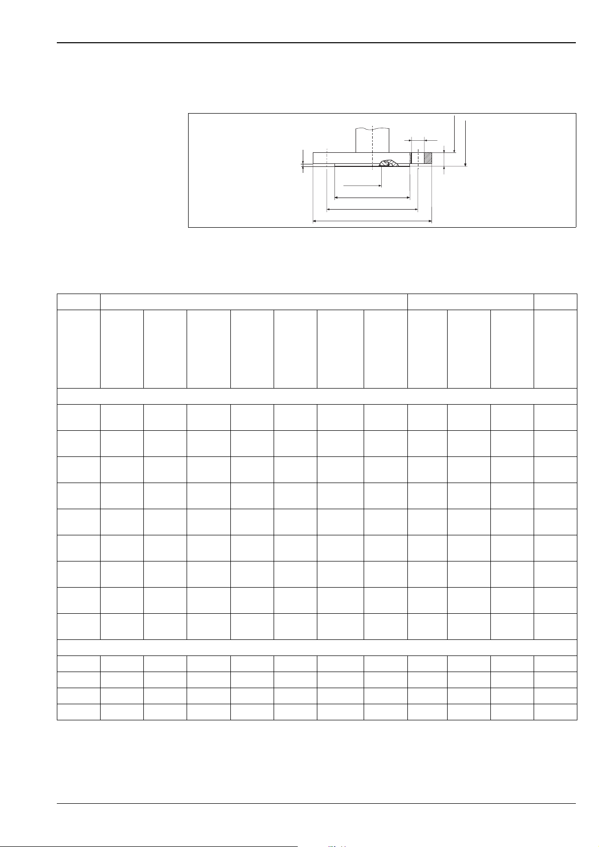
Cerabar S
ANSI flanges, connection dimensions as per ANSI B 16.5, raised face RF
JIS flanges, connection dimensions as per B 2220, Raised face RF
h
g
H
2
Flange Boltholes
Version Material Nominal
diameter
ANSI flange
AN AISI 316/
316L
AE AISI 316/
316L
AQ AISI 316/
316L
AF AISI 316/
316L
AR AISI 316/
316L
AG AISI 316/
316L
AS AISI 316/
316L
AH AISI 316/
316L
AT AISI 316/
316L
2
2
2
2
2
2
2
2
2
1 in 300
1 1/2 in 150
1 1/2 in 300
2 in 150
2 in 300
3 in 150
3 in 300
4 in 150
4 in 300
JIS flange
3
KA AISI 316L
KF AISI 316L
KL AISI 316L
KH AISI 316L
25 A 20 K 125 16 67 1 4 19 90 1.5
3
50 A 10 K 155 16 96 2 4 19 120 2.0
3
80 A 10 K 185 18 127 2 8 19 150 3.3
3
100 A 10 K 210 18 151 2 8 19 175 4.4
2
b
d=Mø28
g
k
D
Process connection PMP71, ANSI flange or JIS flange with raised face RF; material
H: device height = height of device without flange + flange thickness b
For the height h see page 48.
Class/
Nominal
pressure
Diameter Thickness Diameter
raised face
Height
raised
face
Quantity Diameter Hole
Db g f g2k
[in]
[mm]
4.88
lb./sq.in
124
lb./sq.in5127
6.12
lb./sq.in
155.4
lb./sq.in6152.4
7.5
lb./sq.in
190.5
7.5
lb./sq.in
190.5
8.25
lb./sq.in
209.5
lb./sq.in9228.6
lb./sq.in10254
[in]
[mm]
0.69
17.5
0.69
17.5
0.81
20.6
0.75
19.1
0.88
22.3
0.94
23.9
1.12
28.4
0.94
23.9
1.25
31.8
[in]
[mm]
2
50.8
2.88
73.2
2.88
73.2
3.62
91.9
3.62
91.9
5
127
5
127
6.19
157.2
6.19
157.2
[in]
[mm]
0.06
1.6
0.06
1.6
0.06
1.6
0.06
1.6
0.06
1.6
0.06
1.6
0.06
1.6
0.06
1.6
0.06
1.6
40.75
40.62
40.88
40.75
80.75
40.75
80.88
80.75
80.88
[in]
[mm]
19.1
15.7
22.4
19.1
19.1
19.1
22.4
19.1
22.4
circle
[in]
[mm]
3.5
88.9
3.88
98.6
4.5
114.3
4.75
120.7
5
127
6
152.4
6.62
168.1
7.5
190.5
7.88
200.2
P01-PMP71xxx-06-09-xx-xx-009
Flange
1
weight
[kg]
1.3
1.5
2.6
2.4
3.2
4.9
6.7
7.1
11.6
1) Housing weight see page 61
2) Combination of AISI 316 for required pressure resistance and AISI 316L for required chemical resistance (dual rated)
3) AISI 316L/1.4435
Endress+Hauser 47
Page 48
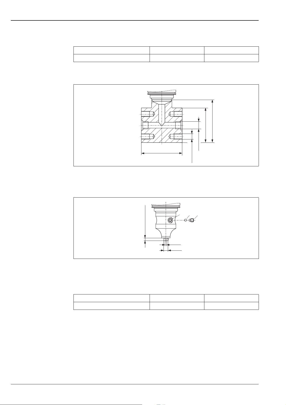
Height h for devices with flange
T14 housing T17 housing
Height h 165 mm 181 mm
Oval flange
63.5
Cerabar S
78.5
75
Version UR: oval flange adapter 1/4-18 NPT, mounting: 7/16-20 UNF
Prepared for diaphragm seal mount
h
5
Version U1: prepared for diaphragm seal mount
1 Hole for filling fluid
2Bearing
3 Threaded pin with an internal hexagon 4 mm
ø2.5
ø7.95
1/4-18 NPT
7/16-20 UNF
P01-PMP71xxx-06-09-xx-xx-007
➀➂➁
P01-PMP75xxx-06-09-xx-xx-xx-005
T14 housing T17 housing
Height h 190 mm 204 mm
48 Endress+Hauser
Page 49
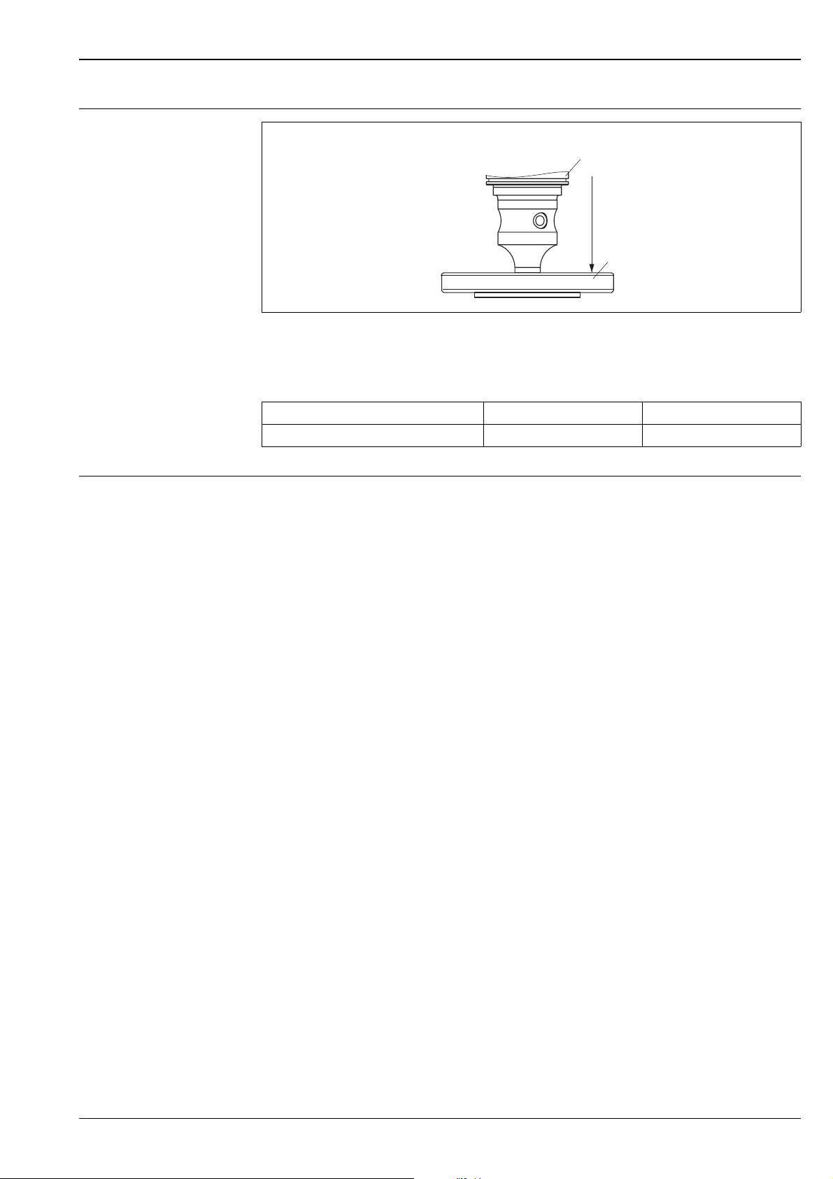
Cerabar S
PMP75 Basic unit
➀
h
➁
P01-PMP75xxx-06-09-xx-xx-012
PMP75 Basic unit with diaphragm seal
1 PMP75 Basic unit
2 Diaphragm seal, here e.g. flange diaphragm seal
T14 housing T17 housing
Height 190 mm 204 mm
Process connections PMP75 (with metallic measuring diaphragm)
Note!
• Some device versions have CRN approval. For a CRN-approved device, a CRN-approved process connection
(→ see page 79, feature 70 "Process connection") has to be ordered with a CSA approval (→ see page 78,
feature 10 "Approval"). Devices with capillary are not CRN-approved. These devices are fitted with a
separate plate bearing the registration number 0F10525.5C.
• Specifications for the "T
Process" are listed in the following tables. These are typical values. The temperature
K
coefficients apply to silicone oil and the membrane material AISI 316L/1.4435. For other filling oils, this
temperature coefficient must be multiplied by the T
correction factor of the corresponding filling oil. For
K
the TK correction factors, see page 63, section "Diaphragm seal filling oils".
• With regard to the temperature coefficient "TKAmbient", devices with a temperature isolator behave like
devices with the same process connection with 1 m capillary.
• In addition, the temperature coefficient "T
Ambient" is listed in relation to the capillary length for the
K
diaphragm seal versions which can be supplied with capillaries as standard. This information is found on
page 63 ff, section "Influence of the temperature on the zero point".
• The weights of the diaphragm seals are given in the tables. See page 61 for the weight of the housing.
• The following drawings are drawings that illustrate how the system works in principle. In other words, the
dimensions of a diaphragm seal supplied can deviate from the dimensions given in this document.
Endress+Hauser 49
Page 50
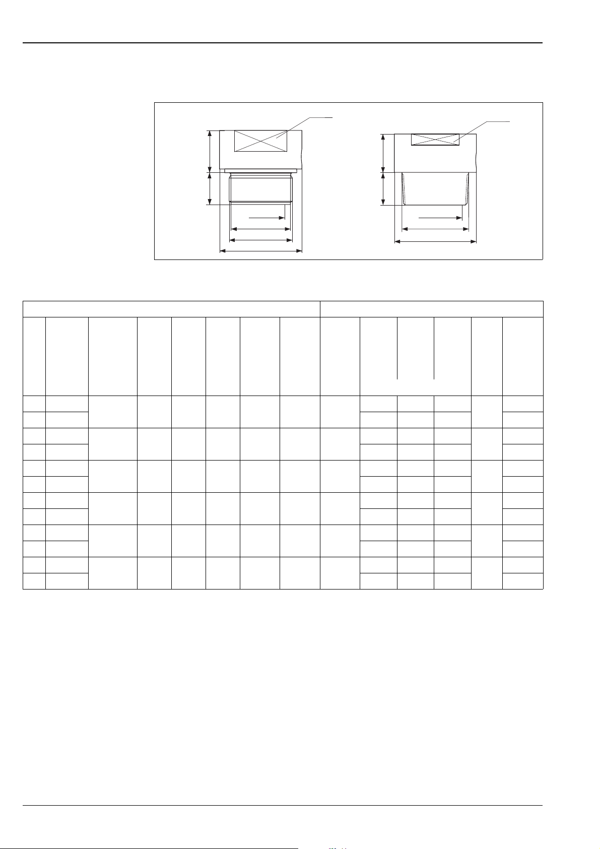
Thread, flush-mounted diaphragm
Cerabar S
SW
AF
h
1
x
d
M
d
1
G
d
2
h
1
x
d
M
NPT
d
2
SW
AF
P01-PMP75xxx-06-09-xx-xx-003
Process connections PMP75, left: thread ISO 228, right: thread ANSI
Threaded connection Diaphragm seal
Version
Material
1
Thread Nomi-
nal
pressure
PN d
Diameter
1
Diameter
d
2
Screw-in
length
x
1
Across
flats
SW/AF d
max. Diaphragm
diameter
M
T
K
Ambient
≤ 40 bar
T
K
Ambient
> 40 bar
T
K
Process
Height Dia-
phragm
seal
weight
h
[mm] [mm] [mm] [mm] [mbar/10 K] [mm] [kg]
1D AISI 316L G 1 A 400 30 39 21 32 30 +16.03 +24.33 +5.17 19 0.4
1E Alloy C276 ––– 0.5
1G AISI 316L G 1 1/2 A 400 43 55 30 41 42 +5.4 +8.18 +1.76 20 0.9
1H Alloy C276 ––– 1.0
1K AISI 316L G 2 400 56 68 30 60 50 +1.76 +2.68 +0.56 20 1.9
1L Alloy C276 ––– 2.1
2A AISI 316L 1 MNPT 400 – 48 28 41 24 +15.66 +24.42 +4.21 37 0.6
2B Alloy C276 ––– 0.7
2D AISI 316L 1 1/2 MNPT 400 – 50 30 41 36 +8.14 +12.39 +2.59 20 0.9
2E Alloy C276 ––– 1.0
2G AISI 316L 2 MNPT 400 – 78 30 65 38 +5.4 +8.18 +2.59 35 1.8
2H Alloy C276 ––– 2,0
1) AISI 316L/1.4435; Alloy C276/2.4819
50 Endress+Hauser
Page 51
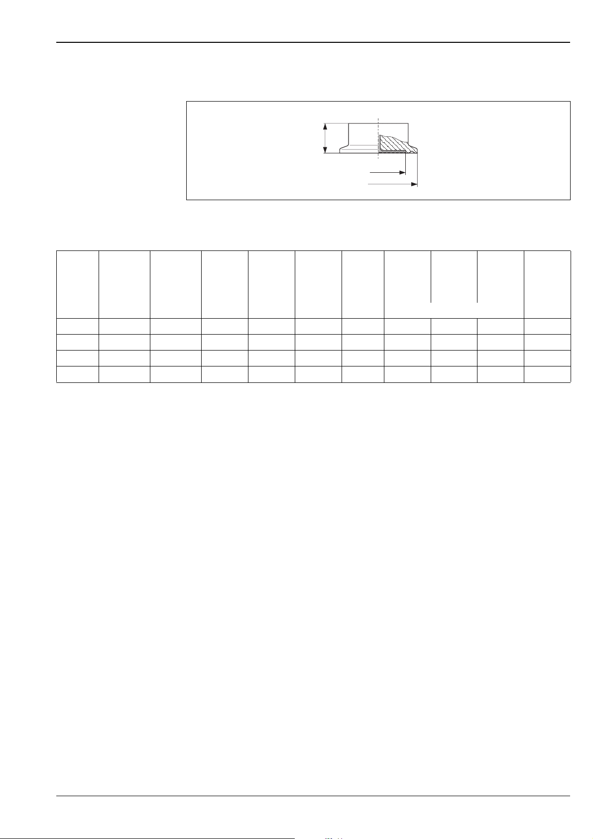
Cerabar S
Tri-Clamp ISO 2852
h
d
M
C
7
P01-FMD78xxx-06-09-xx-xx-005
Process connection PMP75, material: AISI 316L/1.4435, surface roughness of the surfaces in contact with the medium
R
≤ 0.8 µm as standard. Lower surface roughness on request.
a
Version Nominal
diameter
ISO 2852
Nominal
diameter
DIN 32676
Nominal
diameter
Diameter max.
Diaphragm
diameter
C
7
d
M
Height T
h
K
Ambient
≤ 40 bar
T
K
Ambient
> 40 bar
T
K
Process
Diaphragm
seal weight
[in] [mm] [mm] [mm] [mbar/10 K] [kg]
TB DN 25 DN 25 1 50.5 24 37 +15.33 +24.0 +2.85 0.32
1
TC
TD
1
DN 38 DN 40 1 1/2 50.5 34 30 +8.14 +12.39 +1.91 1.0
DN 51 DN 50 2 64 48 30 +3.45 +4.81 +1.28 1.1
TF DN 76.1 – 3 91 73 30 +0.3 +0.35 +0.18 1.2
1) Diaphragm seal versions in conformity with ASME-BPE for use in biochemical processes, wetted surfaces R
to be ordered using feature 60 "Additional option", version "P" in the order code
≤ 0.4 µm (15.75 µin; 180 grit), electropolished;
a
Endress+Hauser 51
Page 52
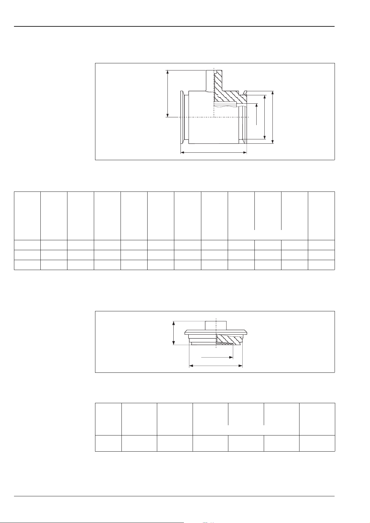
Cerabar S
Tri-Clamp pipe diaphragm seal ISO 2852
h
1
2
D
d
d
L
P01-FMD78xxx-06-09-xx-xx-001
Process connection PMP75, material AISI 316L, surface roughness of the surfaces in contact with the medium Ra≤ 0.8
µm as standard. Lower surface roughness on request.
Version Nominal
diameter
ISO 2852
Nominal
diameter
Diameter Diameter Diameter Height Face-to-
facelength
Dd
1
d
2
hL
T
K
Ambient
≤ 40 bar
T
K
Ambient
> 40 bar
T
K
Process
[in] [mm] [mm] [mm] [mm] [mbar/10 K] [kg]
SB DN 25 1 22.5 43.5 50.5 67 126 +7.75 +8.69 +4.49 1.7
1
SC
SD
1
DN 38 1 1/2 35.5 43.5 50.5 67 126 +5.17 +5.69 +3.46 1.0
DN 51 2 48.6 56.5 64 79 100 +3.56 +3.91 +2.69 1.7
1) Including 3.1 and pressure test as per Pressure Equipment Directive, category II
Varivent N for pipes DN 40 – DN 162
40
d=50
M max.
ø68
P01-FMD78xxx-06-09-xx-xx-006
Process connection PMP75, surface roughness of the surfaces in contact with the medium Ra≤ 0.8 µm as standard. Lower
surface roughness on request.
Diaphragm
seal
weight
Version Material Nominal
pressure
TK
Ambient
≤ 40 bar
T
K
Ambient
> 40 bar
T
Process Diaphragm
K
seal weight
[mbar/10 K] [kg]
TR
1
AISI 316L/
PN 40 +2.26 +3.11 +0.89 1.3
1.4435
1) Diaphragm seal versions in conformity with ASME-BPE for use in biochemical processes, wetted surfaces
R
≤ 0.4 µm (15.75 µin; 180 grit), electropolished; to be ordered using feature 60 "Additional option", version "P" in
a
the order code
52 Endress+Hauser
Page 53
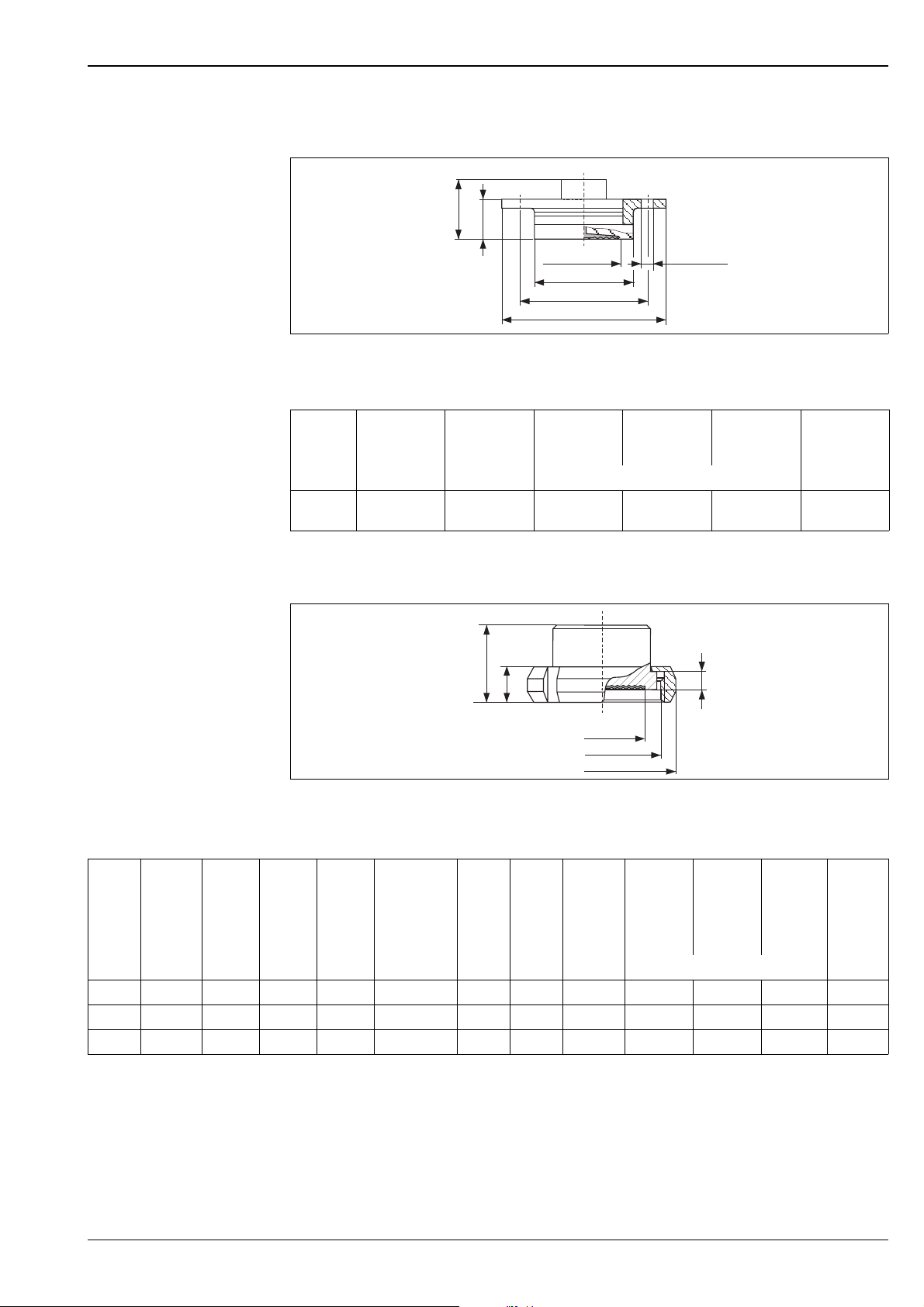
Cerabar S
DRD 65 mm
41
23.6
d =50
M max.
ø65
–1.2
4xø11.5
ø84
ø105
P01-FM78xxx-06-09-xx-xx-002
Process connection PMP75, surface roughness of the surfaces in contact with the medium Ra≤ 0.8 µm as standard. Lower
surface roughness on request.
Version Material Nominal
pressure
TK
Ambient
≤ 40 bar
T
K
Ambient
> 40 bar
T
Process Diaphragm
K
seal weight
[mbar/10 K] [kg]
TK AISI 316L/
PN 25 +2.26 +3.11 +0.89 0,75
1.4435
SMS nozzles with coupling nut
h
m
f
d
M
G
D
P01-PMP75xxx-06-09-xx-xx-009
Process connection PMP75, material AISI 316L/1.4435, surface roughness of the surfaces in contact with the medium
R
≤ 0.8 µm as standard. Lower surface roughness on request.
a
Version Nominal
diameter
Nominal
pressure
Diameter
Adapter
height
Thread Height Height max. dia-
phragm
diameter
T
K
Ambient
≤ 40 bar
T
K
Ambient
> 40 bar
T
K
Process
Weight
diaphragm
seal
Df G mhd
M
[inch] [bar] [mm] [mm] [mm] [mm] [mm] [mbar/10 K] [kg]
TG 1 PN 25 54 3,5 Rd 40 – 1/6 20 42.5 24 +15.66 +24.22 +4.21 0.25
TH 1 1/2 PN 25 74 4 Rd 60 – 1/6 25 57 36 +8.18 +12.39 +2.59 0.65
TI 2 PN 25 84 4 Rd 70 – 1/6 26 62 48 +5.4 +8.18 +1.76 1.05
Endress+Hauser 53
Page 54
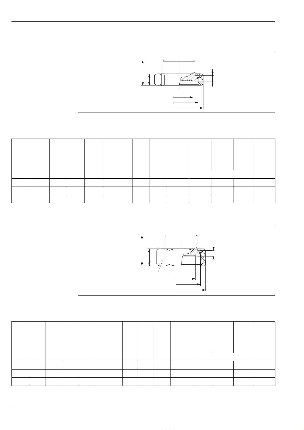
APV-RJT nozzles with coupling nut
Cerabar S
h
m
d
M
f
G
D
P01-PMP75xxx-06-09-xx-xx-010
Process connection PMP75, material AISI 316L/1.4435, surface roughness of the surfaces in contact with the medium
R
≤ 0.8 µm as standard. Lower surface roughness on request.
a
Version Nomi-
nal diameter
Nominal
Diameter
Adapter
height
Thread Height Height max.
pressure
PN D f G m h d
diaphragm
diameter
M
T
K
Ambient
≤ 40 bar
T
K
Ambient
> 40 bar
T
K
Process
Weight
diaphragm
seal
[inch] [bar] [mm] [mm] [mm] [mm] [mm] [mbar/10 K] [kg]
TL 1 PN 40 77 6.5 1 13/16 – 1/8" 22 42.6 21 +15.66 +24.42 +4.21 0.45
TM 1 1/2 PN 40 72 6.4 2 5/16 – 1/8" 22 42.6 28 +8.18 +12.39 +2.59 0.75
TN 2 PN 40 86 6.4 2 7/8 – 1/8" 22 42.6 38 +5.4 +8.18 +1.76 1.2
APV-ISS nozzles with coupling nut
h
f
m
SW/AF
d
M
G
D
P01-PMP75xxx-06-09-xx-xx-011
Process connection PMP75, material AISI 316L/1.4435, surface roughness of the surfaces in contact with the medium
R
≤ 0.8 µm as standard. Lower surface roughness on request.
a
Version Nomi-
nal diameter
Nominal
pressure
Diameter
Adapter
Thread Height Across
flat
height
Df G mAFhd
Height max.
diaphragm
seal
M
T
K
Ambient
≤ 40 bar
T
K
Ambient
> 40 bar
T
K
Process
Weight
Diaphragm
seal
[inch] [bar] [mm] [mm] [mm] [mm] [mm] [mbar/10 K] [kg]
TP 1 PN 40 54.1 4 1 1/2" – 1/8" 30 46.8 50 24 +15.66 +24.42 +4.21 0.4
TQ 1 1/2 PN 40 72 4 2" – 1/8" 30 62 50 34 +8.14 +12.39 +2.59 0.6
TS 2 PN 40 89 4 2 1/2" – 1/8" 30 77 50 45 +5.4 +8.18 +1.76 1.1
54 Endress+Hauser
Page 55
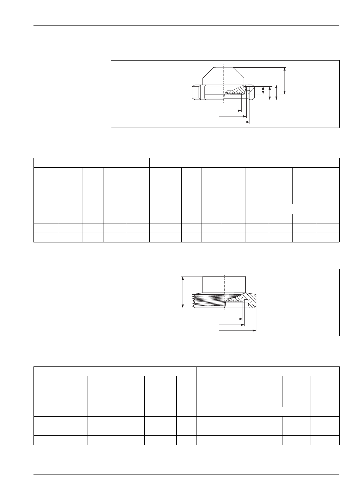
Cerabar S
Taper adapter with coupling nut, DIN 11851
40
f
k
m
d
M
D
G
P01-FMD78xxx-06-09-xx-xx-007
Process connection PMP75, material AISI 316L/1.4435, surface roughness of the surfaces in contact with the medium
R
≤ 0.8 µm as standard. Lower surface roughness on request.
a
Taper adapter Slotted nut Diaphragm seal
Version Nominal
diameter
Nominal
pres-
Diameter
Adapter
height
Thread Height Height max. Dia-
phragm
diameter
sure
Df G kmd
M
[mm] [mm] [mm] [mm] [mm] [mbar/10 K] [kg]
MR DN 50 PN 25 68.5 11 Rd 78 x 1/6" 22 19 52 +2.21 +3.02 +0.88 1.1
MS DN 65 PN 25 86 12 Rd 95 x 1/6" 35 21 66 +1.6 +2.1 +0.6 2.0
MT DN 80 PN 25 100 12 Rd 110 x 1/4" 30 26 81 +0.66 +0.81 +0.4 2.55
T
K
Ambient
≤ 40 bar
T
K
Ambient
> 40 bar
T
K
Process
Diaphragm
seal
weight
Threaded adapter, DIN 11851
h
d
M
d
1
G
P01-FMD78xxx-06-09-xx-xx-008
Process connection PMP75, material AISI 316L/1.4435, surface roughness of the surfaces in contact with the medium
R
≤ 0.8 µm as standard. Lower surface roughness on request.
a
Threaded adapter Diaphragm seal
Version Nominal
diameter
Nominal
pressure
Diameter Thread Height max.
Diaphragm
diameter
d
1
Ghd
M
T
K
Ambient
≤ 40 bar
[mm] [mm] [mm] [mbar/10 K] [kg]
M3 DN 50 PN 25 54 Rd 78 x 1/6" 35 52 +2.21 +3.02 +0.88 0.9
M4 DN 65 PN 25 71 Rd 95 x 1/6" 40 66 +1.6 +2.1 +0.6 1.7
M5 DN 80 PN 25 85 Rd 110 x 1/4" 40 81 +0.66 +0.81 +0.4 2.0
T
K
Ambient
> 40 bar
T
Process Diaphragm
K
seal weight
Endress+Hauser 55
Page 56
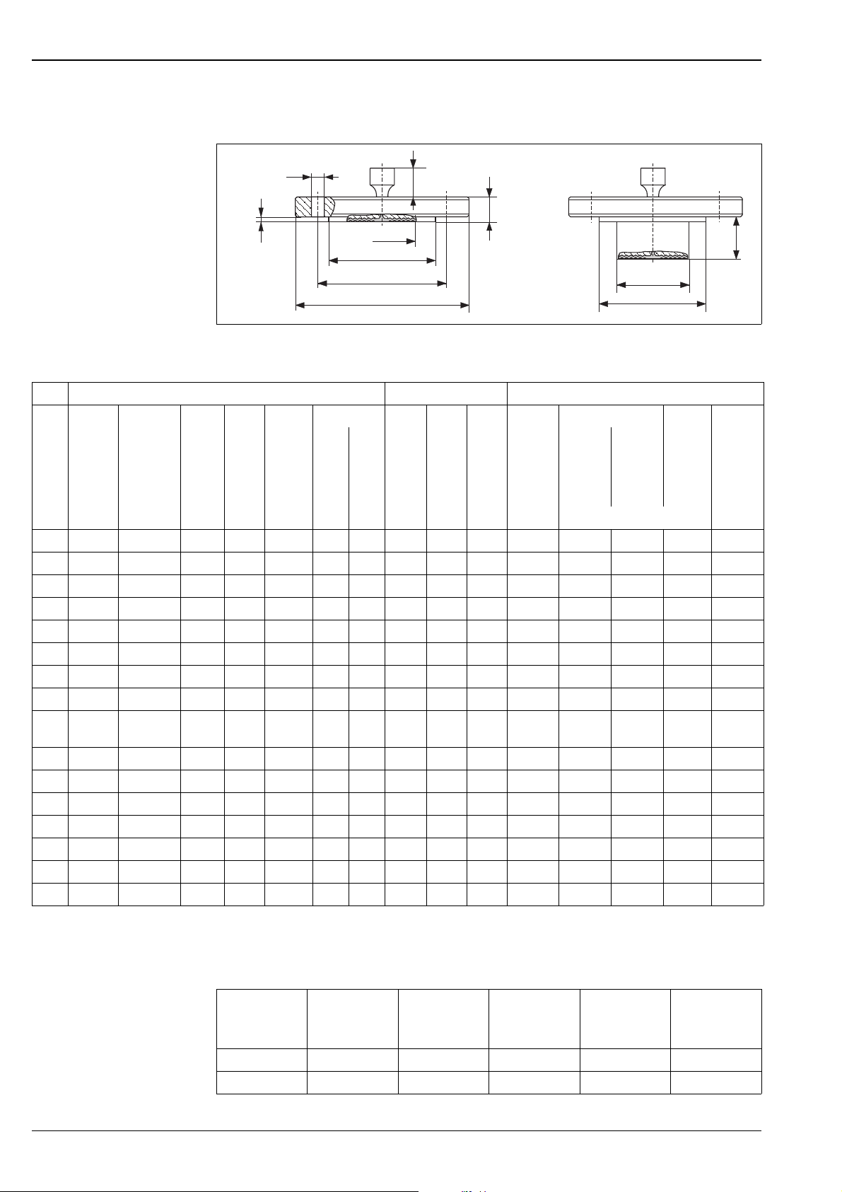
EN/DIN flanges, connection dimensions as per EN 1092-1/DIN 2527 and DIN 2501-1
g
2
f
40
b
d
M
g
Cerabar S
L
k
D
d
3
g
P01-PMP75xxx-06-09-xx-xx-002
Process connection PMP75, EN/DIN flange with flush-mounted diaphragm, material AISI 316L
Flange Boltholes Diaphragm seal
Version
Nominal
diameter
Nominal
pressure
Shape
1
Diameter
Thickness
Raised face Quan-
tity
Diameter
Hole
circle
max.
Diaphragm
dia-
T
Ambient T
K
≤ 40 bar > 40 bar
K
Process
Diaphragm
seal
weight
meter
Db gf g
2
kd
M
[mm] [mm] [mm] [mm] [mm] [mm] [mm] [mbar/10 K] [kg]
CN DN 25 PN 10-40 B1 (D) 115 18 66 3 4 14 85 32 +16.03 +24.33 +5.17 2.1
DN DN 25 PN 63-160 E 140 24 68 2 4 18 100 28 +16.03 +24.33 +5.17 2.5
EN DN 25 PN 250 E 150 28 68 2 4 22 105 28 +16.03 +24.33 +5.17 3.7
E1 DN 25 PN 400 E 180 38 68 2 4 26 130 28 +16.03 +24.33 +5.17 7.0
CP DN 32 PN 10-40 B1 (D) 140 18 77 2.6 4 18 100 34 +8.14 +12.39 +2.59 1.9
CQ DN 40 PN 10-40 B1 (D) 150 18 87 2.6 4 18 110 48 +5.40 +8.18 +1.76 2.2
B3 DN 50 PN 10-40 B1 (D) 165 26 102 3 4 18 125 59 +2.21 +3.02 +1.15 3.0
C3 DN 50 PN 63 B2 (E) 180 26 102 3 4 22 135 59 +2.21 +3.02 +1.15 4.6
EF DN 50 PN 100/
E 195 30 102 3 4 26 145 59 +2.21 +3.02 +1.15 6.2
160
ER DN 50 PN 250 E 200 38 102 3 8 26 150 59 +2.21 +3.02 +1.15 7.7
E3 DN 50 PN 400 E 235 52 102 3 8 30 180 59 +2.21 +3.02 +1.15 14.7
B4 DN 80 PN 10-40 B1 (D) 200 24 138 3.5 8 18 160 89 +0.19 +0.25 +0.11 5.3
C4 DN 80 PN 100 B2 (E) 230 32 138 4 8 24 180 89 +0.19 +0.25 +0.11 8.9
C5 DN 100 PN 100 B2 (E) 265 36 175 5 8 30 210 89 +0.19 +0.25 +0.11 13.7
2
D3
DN 50 PN 10-40 B1 (D) 165 20 102 3 4 18 125 47 +3.45 +4.81 +1.67
D4 2DN 80 PN 10-40 B1 (D) 200 24 138 3.5 8 18 160 72 +0.19 +0.25 +0.7
2
2
1) Designation as per DIN 2527 in brackets
2) 50 mm, 100 mm or 200 mm extension selectable, for extension diameter and weight see the following table
Version Nominal
diameter
Nominal
pressure
Extension
length
Extension
diameter
Diaphragm seal
weight
[mm] [mm] [kg]
D3 DN 50 PN 10-40 50 / 100 / 200 48.3 3.2 / 3.8 / 4.4
D4 DN 80 PN 10-40 50 /100 / 200 76 6.2 / 6.7 / 7.8
56 Endress+Hauser
Page 57
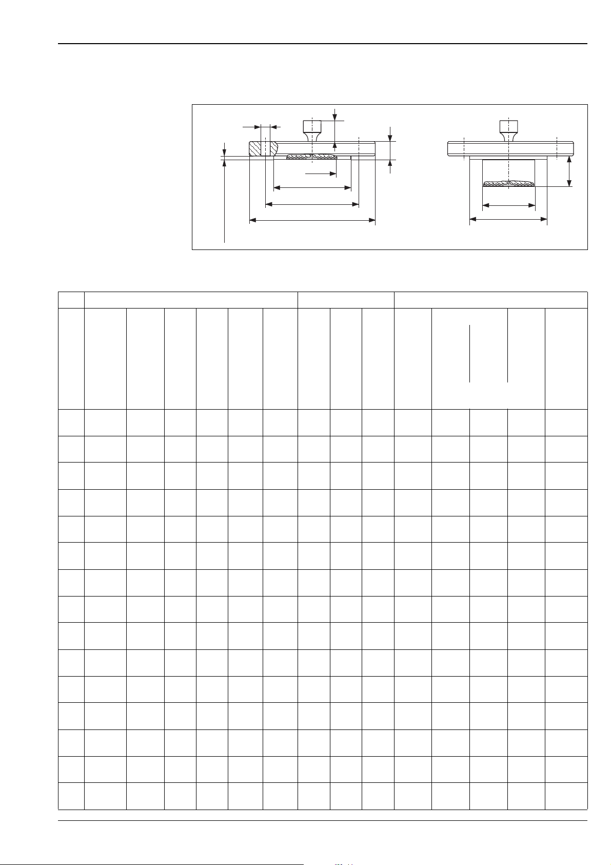
Cerabar S
ANSI flanges B 16.5 RF
g
2
40
b
d
M
L
g
k
D
150, 300 lb/sq.in
0.06 in (1.6 mm)
400 – 2500 lb/sq.in
0.25 in (6.4 mm)
Process connection PMP75, ANSI flange B 16.5 RF with and without extended diaphragm seal
Flange Boltholes Diaphragm seal
Version
Material No-
minal
Class Dia-
meter
Thickness
Raised
face
Quantity
Diameter
Hole
circle
diameter
AC AISI 316/
AN AISI 316/
HC AISI 316/
HN AISI 316/
HO AISI 316/
AE AISI 316/
AQ AISI 316/
AF AISI 316/
2
J3
AR AISI 316/
HF AISI 316/
HR AISI 316/
H3 AISI 316/
AG AISI 316/
AS AISI 316/
1
316L
1
316L
1
316L
1
316L
1
316L
1
316L
1
316L
1
316L
AISI 316/
1
316L
1
316L
1
316L
1
316L
1
316L
1
316L
1
316L
Db g g
[in] [lb./
sq.in]
[in]
[mm]
1 150 4.25
108
1 300 4.88
124
1 400/
600
1 900/
1500
4.88
124
5.88
149.4
1 2500 6.25
158.8
1 1/2 150 5
127
1 1/2 300 6.12
155.4
21506
152.4
21506
152.4
2 300 6.5
165.1
2 400/
600
2 900/
1500
6.5
165.1125.4
8.5
215.9
2 2500 9.25
235250.8
3 150 7.5
190.5
3 300 8.25
209.5
[in]
[mm]
0.56
14.2
0.69
17.5
0.69
17.5
1.12
28.4
1.38
35.1
0.69
17.5
0.81
20.6
0.75
19.1
0.75
19.1
0.88
22.4
1.5
38.1
0.94
23.9
1.12
28.4
[in]
[mm]
2
50.8
2
50.8
2
50.8
2
50.8
2
50.8
2.88
73.2
2.88
73.2
3.62
91.9
3.62
91.9
3.62
91.9
3.62
91.9
3.62
91.9
3.62
91.9
5
127
5
127
[in]
[mm]
40.62
15.7
40.75
19.1
40.75
19.1
41
25.44101.6
41
25.4
40.62
15.7
40.88
22.4
40.75
19.1
40.75
19.1
80.75
19.15127
80.75
19.15127
81
25.4
81.12
28.4
40.75
19.16152.4
80.75
19.16152.4
2
kd
[in]
[mm]
3.12
79.2
3.5
88.9
3.5
88.9
4.25
108
3.88
96.6
4.5
114.3
4.75
120.7
4.75
120.7
6.5
165.1
6.75
171.5
max.
Diaphragm
diameter
M
[in]
[mm]
1.26
32
1.26
32
1.26
32
1.26
32
1.26
32
1.89
48
1.89
48
2.32
59
1.85
47
2.32
59
2.32
59
2.32
59
2.32
59
3.50
89
3.5
89
d
3
g
P01-PMP75xxx-06-09-xx-xx-001
T
Ambient T
K
≤ 40 bar > 40 bar
K
Process
Diaphragm
seal
weight
[mbar/10 K] [kg]
+16.03 +24.33 +5.17 1.2
+16.03 +24.33 +5.17 1.3
+16.03 +24.33 +5.17 1.4
+16.03 +24.33 +5.17 3.2
+16.03 +24.33 +5.17 4.6
+8.14 +12.39 +2.59 1.5
+8.14 +12.39 +2.59 2.6
+2.21 +3.02 +1.15 2.2
+3.45 +4.81 +1.67
2
+2.21 +3.02 +1.15 3.4
+2.21 +3.02 +1.15 4.3
+2.21 +3.02 +1.15 10.3
+2.21 +3.02 +1.15 15.8
+0.19 +0.25 +0.11 5.1
+0.19 +0.25 +0.11 7.0
Endress+Hauser 57
Page 58

Flange Boltholes Diaphragm seal
Version
Material No-
minal
Class Dia-
meter
Thickness
Raised
face
Quantity
Diameter
Hole
circle
diameter
3
J4
AISI 316/
J7 3 AISI 316/
AH AISI 316/
AT AISI 316/
3
J5
J8 3AISI 316/
1
316L
1
316L
1
316L
1
316L
AISI 316/
1
316L
1
316L
Db g g
[in] [lb./
sq.in]
[in]
[mm]
3 150 7.5
190.5
3 300 8.25
209.5
41509
228.6
4 300 10
254
41509
228.6
4 300 10
254
[in]
[mm]
[in]
[mm]
0.94
23.95127
1.12
28.45127
0.94
23.9
1.25
31.8
0.94
23.9
1.25
31.8
6.19
157.2
6.19
157.2
6.19
157.2
6.19
157.2
[in]
[mm]
40.75
19.16152.4
80.88
22.4
80.75
19.1
80.88
22.4
80.75
19.1
80.88
22.4
2
kd
[in]
[mm]
6.62
168.1
7.5
190.5
7.88
200.2
7.5
190.5
7.88
200.2
max.
Diaphragm
diameter
M
[in]
[mm]
2.83
72
2.83
72
3.50
89
3.50
89
3.50
89
3.50
89
Cerabar S
T
Ambient T
K
≤ 40 bar > 40 bar
K
Process
[mbar/10 K] [kg]
+0.19 +0.25 +0.7
+0.19 +0.25 +0.7
+0.19 +0.25 +0.11 7.2
+0.19 +0.25 +0.11 11.7
+0.19 +0.25 +0.11
+0.19 +0.25 +0.11
Diaphragm
seal
weight
2
2
2
2
1) Combination of AISI 316 for required pressure resistance and AISI 316L for required chemical resistance (dual rated)
2) 2", 4", 6" or 8" extension selectable, for extension diameter and weight see the following table
Version Nominal
diameter
Class Extension
length
[in] [lb./sq.in] [in] [(mm)] [in] [(mm)] [kg]
J3 2 150 – 2 (50.8)
– 4 (101.6)
–6 (152.4)
–8 (203.2)
J4 3 150 – 2 (50.8)
– 4 (101.6)
–6 (152.4)
–8 (203.2)
J7 3 300 – 2 (50.8)
– 4 (101.6)
–6 (152.4)
–8 (203.2)
J5 4 150 – 2 (50.8)
– 4 (101.6)
–6 (152.4)
–8 (203.2)
J8 4 300 – 2 (50.8)
– 4 (101.6)
–6 (152.4)
–8 (203.2)
Extension
diameter
Diaphragm seal
weight
1.9 (48.3) –3.0
–3.4
–3.9
–4.4
2.99 (75.9) –6.0
–6.6
–7.1
–7.8
2.99 (75.9) –7.9
–8.5
–9.0
–9.6
3.7 (94)–8.6
–9.9
–11.2
–12.4
3.7 (94) –13.1
–14.4
–15.7
–16.9
58 Endress+Hauser
Page 59
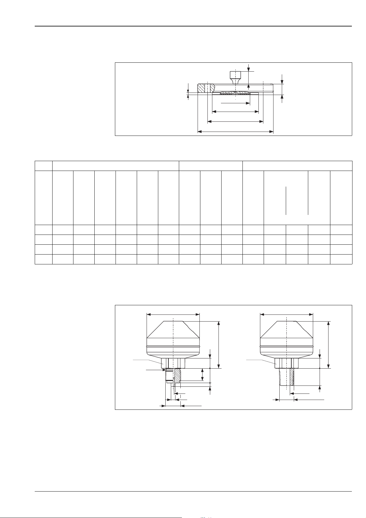
Cerabar S
JIS flange B 2220
40
f
d
M
g
k
D
Process connection PMP75, JIS flange, material AISI 316L
Flange Boltholes Diaphragm seal
Version
Nominal
diameter
Nominal
pressure
Diameter
Thickness
Diameter
raised
face
Height
raised
face
Quantity
Diameter
Hole
circle
max.
Diaphragm
diameter
Db g f g
2
kd
M
[mm] [mm] [mm] [mm] [mm] [mm] [mm] [mbar/10 K] [kg]
KA 25 A 10 K 125 14 67 1 4 19 90 32 +16.03 +24.33 +5.17 1.5
KF 50 A 10 K 155 16 96 2 4 19 120 59 +2.21 +3.02 +1.15 2.3
KL 80 A 10 K 185 18 127 2 8 19 150 89 +0.19 +0.25 +0.11 3.3
KH 100 A 10 K 210 18 151 2 8 19 175 89 +0.19 +0.25 +0.11 4.4
b
T
Ambient TK
K
≤ 40 bar > 40 bar
P01-PMP75xxx-06-09-xx-xx-000
Process
Diaphragm
seal
weight
1
1) Housing weight see page 61
Separator ISO 228 G 1/2 A and ANSI 1/2 MNPT
ø72.6 ø72.6
ø72.6
70
SW 30
AF 30
ø18.4
17
14
20
3
ø4
ø6
G 1/2A
Process connection PMP75, versions "UA" and "UB", welded, material AISI 316L
SW 30
AF 30
70
14
21.5
ø11.4
1/2 - 14 NPT
P01-PMP75xxx-06-09-xx-xx-004
Endress+Hauser 59
Page 60
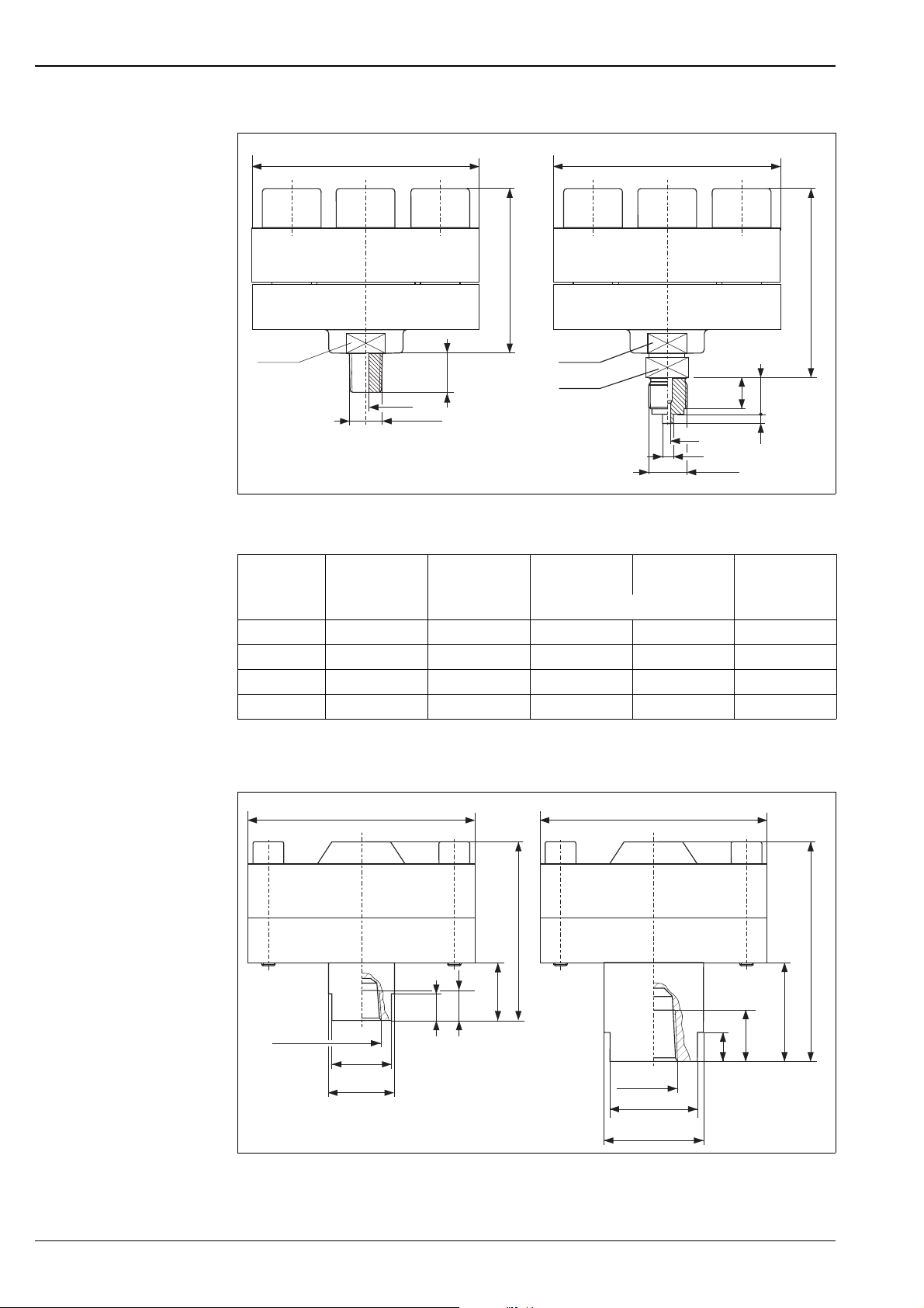
Cerabar S
ø115
ø115
84
SW 36
19
ø2.5
SW 36
SW 22
17
1/2 NPT
ø4
ø6
G 1/2A
Process connection PMP75, versions "UC" and "UD", screwed, material AISI 316L, with metallic seal
Version Description Nominal
pressure
TK Ambient TK Process Diaphragm
seal weight
[mbar/10 K] [kg]
UA ISO 228 G 1/2 A PN 160 +0.9 +0.3 1.43
UB ANSI 1/2 MNPT PN 160 +0.9 +0.3 1.43
UC ISO 228 G 1/2 B PN 400 +3.45 +1.28 4.75
DU ANSI 1/2 MNPT PN 400 +3.45 +1.28 4.75
92.5
20
3
P01-PMP75xxx-06-09-xx-xx-007
1/2 NPT und 1 NPT Off line thread
ø118
76
26
19
12
1/2 NPT
SW 27
27 AF
ø30
Process connection PMP75, versions "UG" and "UL", screwed, material AISI 316L , seal Viton
ø118
1 NPT
SW 36
36 AF
ø52
27
15
P01-PMP75xxx-06-09-xx-xx-008
94.5
44.5
60 Endress+Hauser
Page 61

Cerabar S
Version Description Nominal
UG 1/2 NPT PN 250 +3.45 +1.28 4.75
UH 1 NPT PN 250 +3.45 +1.28 5.0
Weight Housing
With electronic insert and
on-site display
With electronic insert and
without on-site display
Process connections
→ See corresponding process connection, page 34 ff.
Material T14 housing:
• T14 housing, selectable:
– Die-cast aluminium with protective powder-coating on polyester basis: RAL 5012 (blue),
cover: RAL 7035 (grey)
– Precision cast stainless steel AISI 316L (1.4435)
• External operation (keys and key covering): Polycarbonate PC-FR Lexan UL 940 UL94VO,
RAL 7035 (grey)
• Sight glass:
– Aluminium housing: Polycarbonat (PC), for Dust-Ex, EEx d, FM XP and CSA XP: Mineral glass
– Stainless steel housing: Mineral glass
• Cable gland: Polyamid (PA)
• Bind plug: PBT-GF30 FR,
for Dust Ex, EEx d, FM XP and CSA XP: AISI 316L (1.4435)
• Seal for cable gland and plug: Silicone (VMQ)
• O-ring for cover sealing: EPDM
• Nameplates: AISI 304 (1.4301)
T17 housing:
• Housing: Stainless steel AISI 316L (1.4404)
• Sight glass: Polycarbonat (PC) or mineral glass
• Cable gland: Polyamid PA, for Dust-Ex: CuZn nickel-plated
• Bind plug: PBT-GF30 FR, for Dust-Ex: AISI 316L (1.4435)
• Seal for cable gland and plug: Silicone (VMQ)
• Pressure compensation filter: PA6 GF10, O-Ring: Silicone (VMQ)
• O-ring for cover sealing: Silicone (VMQ)
• Nameplates: lasered
Miscellaneous:
• Process diaphragm PMC71: Al
(→ See also www.endress.com/ceraphire)
• Mounting accessories: Mounting kit with screws AISI 304 (1.4301)
• Capillary: AISI 316 Ti (1.4571)
• Protective hose for capillary: AISI 304 (1.4301)
• External earth terminal: AISI 304 (1.4301)
→ For process connections, process diaphragms, seals and filling oils see ordering information, page 70 ff.
TK Ambient TK Process Diaphragm seal
pressure
[mbar/10 K] [kg]
T14 T17
Aluminium AISI 316L/1.4435 AISI 316L/1.4404
1.2 kg 2.1 kg 1.2 kg
1.1 kg 2.0 kg 1.1 kg
(Aluminium-oxide-ceramic), ultrapure 99.9%
2O3
weight
Endress+Hauser 61
Page 62

Cerabar S
Planning instructions, diaphragm seal systems
Applications Diaphragm seal systems should be used if the process media and the device should be separated. Diaphragm
seal systems offer clear advantages in the following instances:
• In the case of high process temperatures (→ See also page 32, section "Process temperature limits".)
• For aggressive media
• If good and rapid measuring point cleaning is necessary
• If the measuring point is exposed to vibrations
• For mounting locations that are difficult to access
• For very humid mounting locations
Planning instructions Diaphragm seals are separating equipment between the measuring system and the process medium.
A diaphragm seal system consists of:
• A diaphragm seal in a one-sided system
• Capillary tube
• Fill fluid and
• A pressure transmitter.
The process pressure acts via the diaphragm seal membrane on the liquid-filled system, which transfers the
process pressure via the capillary tube onto the sensor of the pressure transmitter.
Endress+Hauser delivers all diaphragm seal systems as welded versions. The system is hermetically sealed,
which ensures the highest reliability.
Note!
The correlations between the individual diaphragm seal components are presented in the following section.
For further information and comprehensive diaphragm seal system designs, please contact your local
Endress+Hauser Sales Center.
Diaphragm seal
The diaphragm seal determines the application range of the system by
• the diaphragm diameter
• the diaphragms: stiffness and material
• the design (oil volume).
Diaphragm diameter
The larger the diaphragm diameter (less stiffness), the smaller the temperature effect on the measurement
result.
Note: To keep the temperature effect in practice-oriented limits, you should select diaphragm seals with a
nominal diameter of ≥ DN 80, in as far as the process connection allows for it.
Diaphragm stiffness
The stiffness is dependent on the diaphragm diameter, the material, any available coating and on the diaphragm
thickness and shape. The diaphragm thickness and the shape are defined constructively. The stiffness of a
diaphragm seal membrane influences the temperature operating range and the measuring error caused by
temperature effects.
Capillary
Capillaries with an internal diameter of 1 mm are used as standard.
The capillary tube influences the T
time of a diaphragm seal system as a result of its length and internal diameter.
→ See also page 63 ff, sections "Influence of the temperature on the zero point" and "Ambient temperature
range".
→ Observe the installation instructions regarding capillary tubes. See page 67 ff, section "Installation
instructions".
zero point, the ambient temperature operating range and the response
K
62 Endress+Hauser
Page 63

Cerabar S
Diaphragm seal filling oils
Filling oil
When selecting the filling oil, fluid and ambient temperature as well as the operating pressure are of crucial
importance. Observe the temperatures and pressures during commissioning and cleaning. A further selection
criterion is the compatibility of the filling oil with the requirements of the process medium. For this reason,
only filling oils that are harmless to health are used in the food industry, such as vegetable oil or silicone oil
→ See also the following section "Diaphragm seal filling oils" section.
The filling oil used influences the T
zero point and the temperature operating range of a diaphragm seal system
K
and the response time. → See also page 63 ff, section "Influence of the temperature on the zero point".
Pressure transmitter
The pressure transmitter influences the temperature operating range, the T
zero point and the response time
K
as a result of its volume change. The volume change is the volume that has to be shifted to pass through the
complete measuring range.
Pressure transmitters from Endress+Hauser are optimised with regard to minimum volume change.
Version 1Filling oil Permissible
A, H, 1 or 2 Silicone oil –40...+180°C
G, 3 or 4 High
temperature oil
F or N Inert oil –40...+80°C
D Vegetable oil –10...+120°C
1) Version for feature 90 in the order code
Influence of the temperature on the zero point
temperature range at
0.05 bar ≤ p
(–40...+356°F)
–10...+200°C
(+14...+392°F)
(–40...+176°F)
(+14...+248°F)
A temperature change results in a volume change of the filling oil. The volume change is dependent on the
coefficient of thermal expansion of the filling oil and on the volume of the filling oil at calibration temperature
(constant in the range: +21 to +33°C (+69.8 to 91.4°F)). → See also page 48, "Filling oils, technical data"
section.
For example, the filling oil expands in the event of a temperature increase. The additional volume presses
against the diaphragm seal membrane. The stiffer a diaphragm is, the greater its return force, which counteracts
a volume change and acts on the measuring cell together with the operating pressure, thus shifting the zero
point. For the "T
connections PMP75".
The following diagrams display the temperature coefficient "TK Ambient" dependent on the capillary length.
The following application is displayed: capillary temperature and transmitter temperature (ambient
temperature) change, the process temperature corresponds to the calibration temperature.
The temperature coefficients obtained from the diagrams apply to silicone oil and the membrane material
AISI 316L/1.4435. For other filling oils, these temperature coefficients must be multiplied by the T
factor of the corresponding filling oil. For the TK correction factors, see page 63,
section "Diaphragm seal filling oils".
With regard to the temperature coefficient "T
with the same process connection with 1 m capillary.
≤ 1 bar
abs
Permissible
temperature range
at p
≥ 1 bar
abs
–40...+250°C
(–40...+482°F)
–10...+350°C
(+14...+662°F)
–40...+175°C
(–40...+347°F)
–10...+200°C
(+14...+392°F)
Process" and "TK Ambient (for devices without capillary)", see page 49 ff, section "Process
K
Density Viscosity Coefficient
3
[g/cm
][cSt at
25°C
(77°F)]
0.96 100 0.00096 1 suitable for foods
1.07 37 0.0007 0.72 high temperatures
1.87 27 0.000876 0.91 Oil for ultra pure gas
0.94 9.5 0.00101 1.05 suitable for foods
Ambient", devices with temperature isolator behave like devices
K
of thermal
expansion
[1/K]
T
K
correction
factor
Note
and oxygen
applications
FDA 21 CFR 172.856
correction
K
Endress+Hauser 63
Page 64
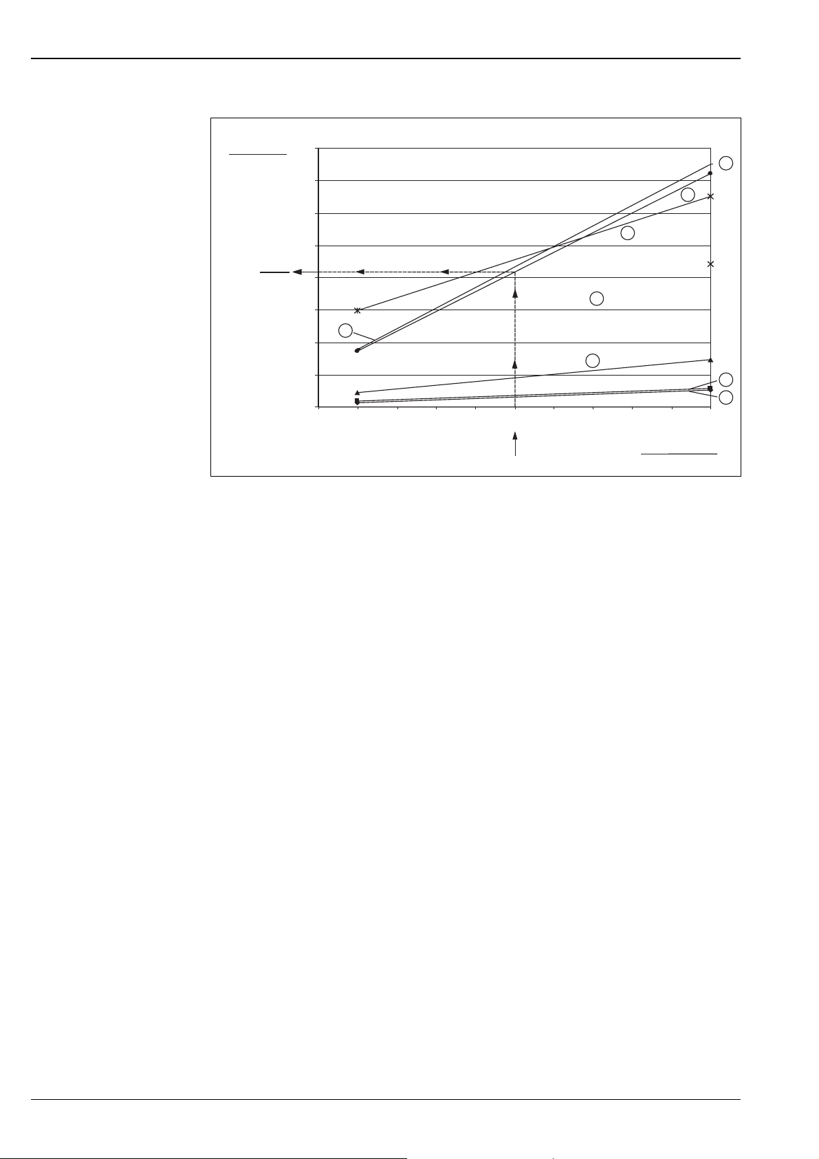
PN ≤ 40 bar
T Ambient
K
[mbar/10 K]
8.4
Diagram TK Ambient dependent on the capillary length for PMP75, PN ≤ 40 bar
mbar
10 K
16
14
12
10
8
6
7
4
2
0
01234 5678910
Cerabar S
7
6
5
4
3
2
1
Capillary length
[m]
P01-PMP75xxx-05-xx-xx-xx-007
Example for:
– Diaphragm seal versions "B3, EN/DIN flange DN 50 PN 10-40 B1, AISI 316L"
– Capillary length: 5 m
– Ambient temperature, capillary/transmitter: 45°C
– Filling oil: silicone oil
1. Select characteristic curve type for the diaphragm seal versions "B3" in accordance with the following
table.
Result: characteristic curve type 6
2. Obtain value for T
Ambient from the diagram.
K
Result: 8.4 mbar/10 K
3. T
Ambient
– T
= 45°C – 25°C = 20°C ⇒ 8.4 mbar/10 K x 20 K = 16.8 mbar
Calibration
Result: In this application, the zero point is shifted by 16.8 mbar.
Note!
• The influence of temperature on the zero point can be corrected with position calibration.
• The temperature influence can be minimised by using a filling oil with a smaller coefficient of thermal
expansion, shorter capillary, diaphragm seal with larger diaphragm diameter or by using a smaller capillary
internal diameter.
64 Endress+Hauser
Page 65
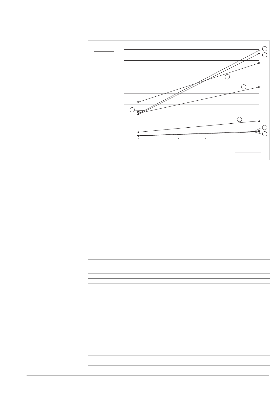
Cerabar S
T Ambient
K
[mbar/10 K]
16
PN > 40 bar
14
12
10
8
6
7
4
2
0
01234 5678910
Diagram TK Ambient dependent on the capillary length for PMP75, PN > 40 bar
7
6
5
4
3
2
1
Capillary length
[m]
P01-PMP75xxx-05-xx-xx-xx-005
Characteristic
curve type
1 B4 EN/DIN flange DN 80 PN 10-40 B1, AISI 316L
2 TF Tri-Clamp, ISO 2852 DN 76.1 (3"), AISI 316L/1.4435
3 MT DIN 11851 DN 80 PN 25, AISI 316L/1.4435
4 SD Pipe diaphragm seal Tri-Clamp, ISO 2852 DN 51 (2"), AISI 316L
5 SC Pipe diaphragm seal Tri-Clamp, ISO 2852 DN 38 (1 1/2"), AISI 316L
6 B3 EN/DIN flange DN 50 PN 1040 B1, AISI 316L
7 TR Varivent Type N for tubes DN 40 – DN 162, PN 40, AISI 316L/1.4435
Version Diaphragm seal
C4 EN/DIN flange DN 80 PN 100 B2, AISI 316L
C5 EN/DIN flange DN 100 PN 100 B2, AISI 316L
KL JIS flange 10K 80A RF, AISI 316L
KH JIS flange 10K 100A RF, AISI 316L
D4 EN/DIN flange DN 80, PN 10-40 B1, Extensions: 50 mm/100 mm/200 mm, AISI 316L
AG ANSI flange 3" 150 lbs RF, AISI 316/316L
AS ANSI flange 3" 300 lbs RF, AISI 316/316L
AH ANSI flange 4" 150 lbs RF, AISI 316/316L
AT ANSI flange 4" 300 lbs RF, AISI 316/316L
J4 ANSI flange 3" 150 lbs RF, Extensions: 2"/4"/6"/8", AISI 316/316L
J7 ANSI flange 3" 300 lbs RF, Extensions: 2"/4"/6"/8", AISI 316/316L
J5 ANSI flange 4" 150 lbs RF, Extensions: 2"/4"/6"/8", AISI 316/316L
J8 ANSI flange 4" 300 lbs RF, Extensions: 2"/4"/6"/8", AISI 316/316L
M5 DIN 11851 DN 80 PN 25 socket, AISI 316L/1.4435
C3 EN/DIN flange DN 50 PN 63 B2, AISI 316L
EF EN/DIN flange DN 50 PN 100-160 E, AISI 316L
ER EN/DIN flange DN 50 PN 250 E, AISI 316L
E3 EN/DIN flange DN 50 PN 400 E, AISI 316L
AF ANSI flange 2" 150 lbs RF, AISI 316/316L
AR ANSI flange 2" 300 lbs RF, AISI 316/316L
HF ANSI flange 2" 400/600 lbs RF, AISI 316/316L
HR ANSI flange 2" 900/1500 lbs RF, AISI 316/316L
H3 ANSI flange 2" 2500 lbs RF, AISI 316/316L
KF JIS 10K 50A RF, AISI 316L
MR DIN 11851 DN 50 PN 25, AISI 316L/1.4435
MS DIN 11851 DN 65 PN 25, AISI 316L/1.4435
M3 DIN 11851 DN 50 PN 25 socket, AISI 316L/1.4435
M4 DIN 11851 DN 65 PN 25 socket, AISI 316L/1.4435
TK DRD 65 mm, PN 25, AISI 316L/1.4435
Endress+Hauser 65
Page 66
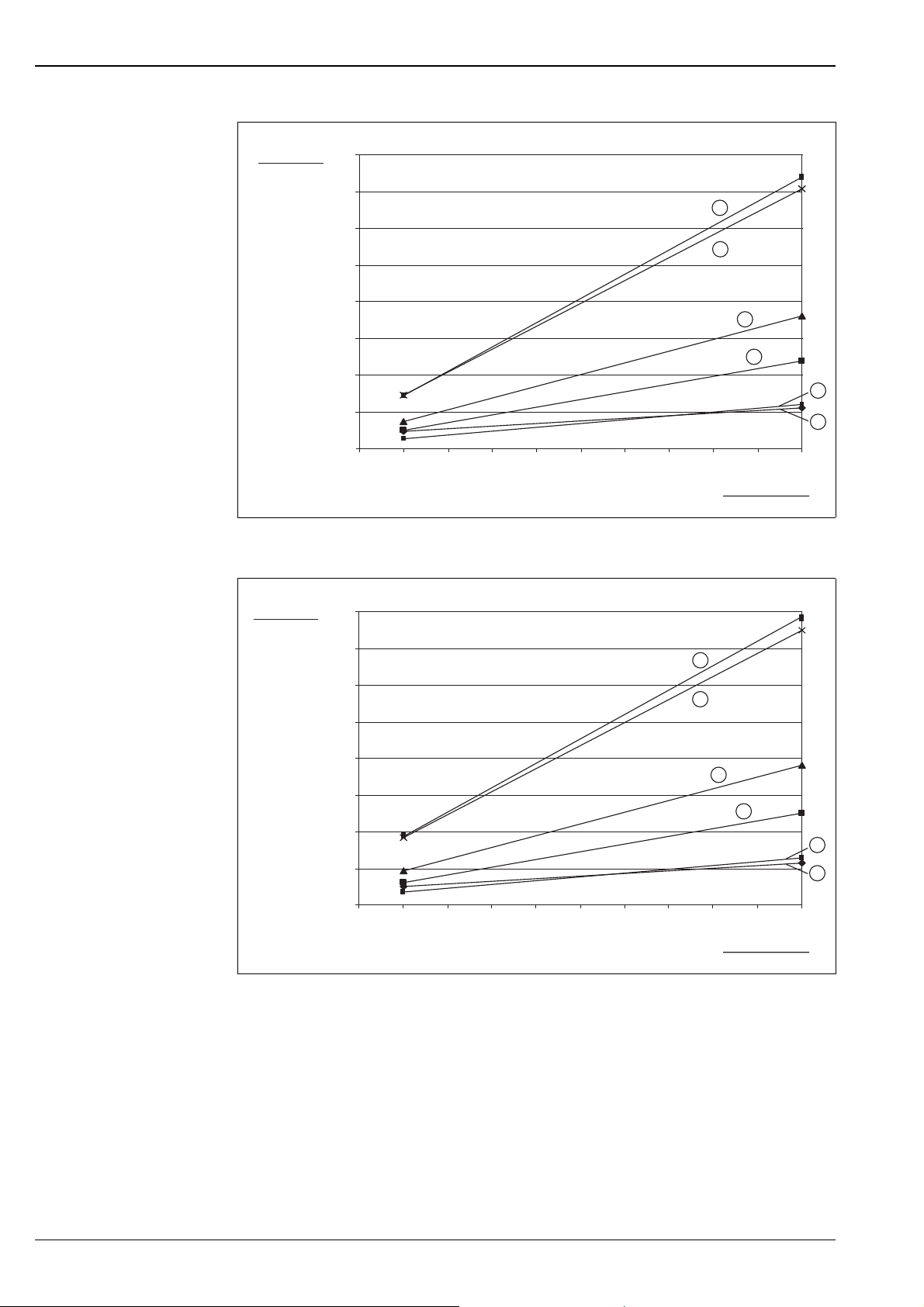
Cerabar S
T Ambient
K
[mbar/10 K]
160
140
120
100
80
60
40
20
0
01234 5678910
Diagram TK Ambient dependent on the capillary length for PMP75, PN ≤ 40 bar
PN ≤ 40 bar
13
12
11
10
9
8
Capillary length
[m]
P01-PMP75xxx-05-xx-xx-xx-008
T Ambient
K
[mbar/10 K]
160
PN > 40 bar
140
120
100
80
60
40
20
0
01234 5678910
Diagram TK Ambient dependent on the capillary length for PMP75, PN > 40 bar
13
12
11
10
99
8
Capillary length
[m]
P01-PMP75xxx-05-xx-xx-xx-009
66 Endress+Hauser
Page 67

Cerabar S
Characteristic
curve type
8 SB Pipe diaphragm seal Tri-Clamp, ISO 2852 DN 25 (1"), AISI 316L
9 D3 EN/DIN flange PN10-40 B1, Extensions: 50 mm/100 mm/200 mm, AISI 316L
10 CQ EN/DIN flange DN 40 PN 10-40 B1, AISI 316L
11 CP EN/DIN flange DN32 PN 10-40 B1, AISI 316L
12 CN EN/DIN flange PN 10-40 B1, AISI 316L
13 TB Tri-Clamp, ISO 2852 DN 25 (1"), DIN 32676 DN 25, AISI 316L/1.4435
Version Diaphragm seal
J3 ANSI flange 2" 150 lbs, Extensions: 2"/4"/6"/8", AISI 316/316L
TD Tri-Clamp, ISO 2852 DN 51 (2"), AISI 316L/1.4435
TI SMS 2" PN 25, AISI 316L/1.4435
TN APV-RJT 2" PN 40, AISI 316L/1.4435
TS APV-ISS 2" PN 40, AISI 316L/1.4435
AE ANSI flange 1 1/2" 150 lbs RF, AISI 316/316L
AQ ANSI flange 1 1/2" 300 lbs RF, AISI 316/316L
TC Tri-Clamp, ISO 2852 DN 38 (1 1/2"), DIN 32676 DN 40, AISI 316L/1.4435
TH SMS 1 1/2" PN 25, AISI 316L/1.4435
TM APV-RJT 1 1/2" PN 40, AISI 316L/1.4435
TS APV-ISS 1 1/2" PN 40, AISI 316L/1.4435
DN EN/DIN flange PN 64-160 E, AISI 316L
EN EN/DIN flange PN 250 E, AISI 316L
E1 EN/DIN flange PN 400 E, AISI 316L
AC ANSI flange 1" 150 lbs RF, AISI 316/316L
AN ANSI flange 1" 300 lbs RF, AISI 316/316L
HC ANSI flange 1" 400/600 lbs RF, AISI 316/316L
HN ANSI flange 1" 900/1500 lbs RF, AISI 316/316L
HO ANSI flange 1" 2500 lbs RF, AISI 316/316L
KA JIS flange 10K 25 A RF, AISI 316L
Ambient temperature range The filling oil, capillary length, capillary internal diameter, process temperature and the oil volume of the
diaphragm seal determine the ambient temperature operating range of the diaphragm seal system.
The operating range can be extended by using a filling oil with a smaller coefficient of expansion and by using
shorter capillaries.
Installation instructions Instructions for diaphragm seal systems
• The diaphragm seal together with the transmitter form a closed, calibrated system, which is filled through
ports in the diaphragm seal and in the measurement system of the transmitter. These ports are sealed and
must not be opened.
• In the case of devices with diaphragm seals and capillaries, the zero point shift caused by the hydrostatic
pressure of the filling liquid column in the capillaries must be taken into account when selecting the
measuring cell. If a measuring cell with a small measuring cell is selected, the sensor nominal range can be
overdriven as a result of position adjustment. See the following diagram and the following example.
• When using a mounting bracket, sufficient strain relief must be allowed for in order to prevent the capillary
bending down (bending radius ≥ 100 mm).
Installation instructions
In order to obtain more precise measurement results and to avoid a defect in the device, mount the capillaries
as follows:
• vibration-free (in order to avoid additional pressure fluctuations)
• not in the vicinity of heating or cooling lines
• insulate at colder or warmer ambient temperatures
• with a bending radius of ≥ 100 mm.
Endress+Hauser 67
Page 68
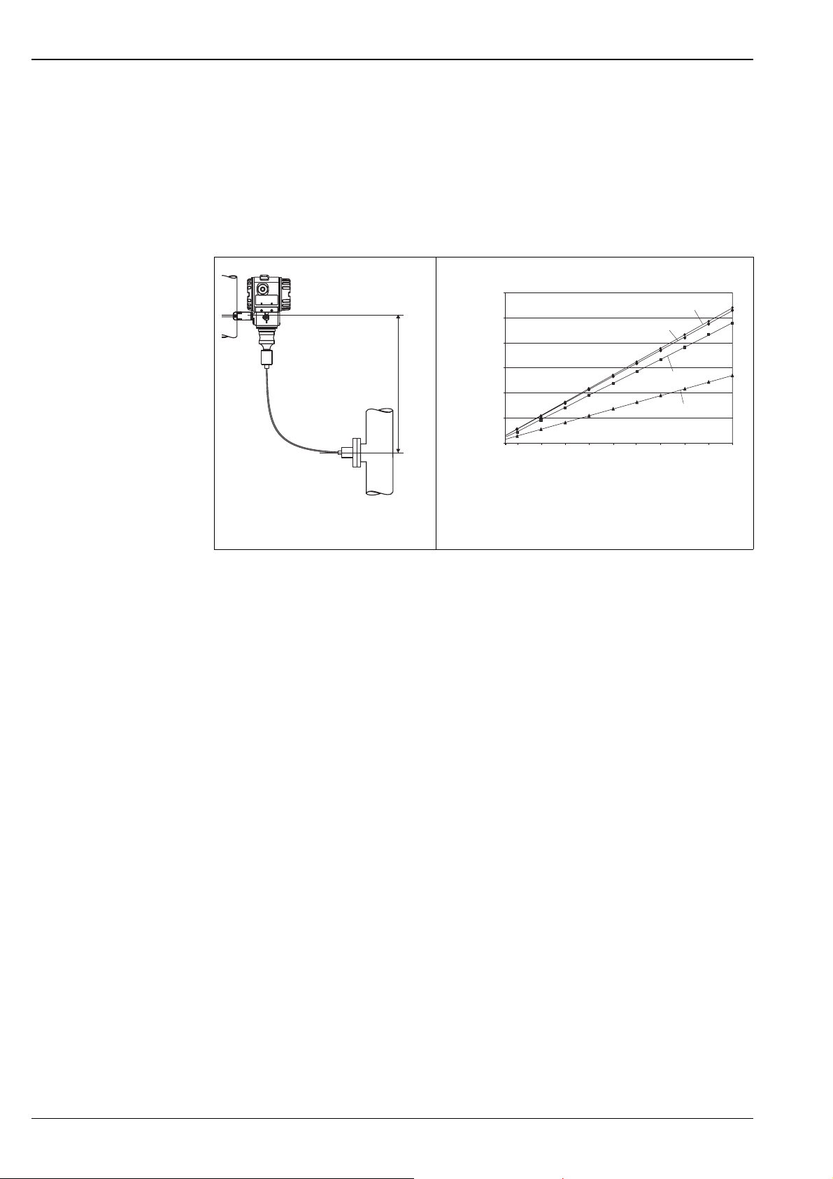
Cerabar S
FIELDTERMINALS
Vacuum applications
For applications under vacuum, Endress+Hauser recommends mounting the pressure transmitter below the
diaphragm seal. A vacuum load of the diaphragm seal caused by the presence of fill fluid in the capillary
prevents is hereby prevented.
When the pressure transmitter is mounted above the diaphragm seal, the maximum height difference H1 in
accordance with the following illustration on the left must not be exceeded. The maximum height difference
is dependent on the density of the filling oil and the smallest ever pressure that is permitted to occur at the
diaphragm seal (empty tank), see the following illustration, on the right.
FIELDTERMINALS
P01-PMx7xxxx-11-xx-xx-xx-008
Installation above the diaphragm seal
12.0
H1
10.0
8.0
6.0
4.0
Height difference H1 [m]
2.0
0.0
200
50 100 300 400 500 600 700 800 900 1000
Pressure at diaphragm seal [mbar
Silicone oil
High temperature
oil
Diagram of maximum installation height above the diaphragm seal for
vacuum applications
Vegetable oil
Inert oil
P01-PMx7xxxx-05-xx-xx-xx-011
abs
]
68 Endress+Hauser
Page 69

Cerabar S
Certificates and approvals
CE mark The device meets the legal requirements of the relevant EC directives.
Endress+Hauser confirms that the device has been successfully tested by applying the CE mark.
Ex approvals •ATEX
•FM
•CSA
•NEPSI
•IECEx
•TIIS
• GOST on request
All explosion protection data are given in separate documentation which is available upon request. The Ex
documentation is supplied as standard with all devices approved for use in explosion hazardous areas.
→ See also page 82 ff, sections "Safety Instructions" and "Installation/Control Drawings".
Marine certificate •GL
•ABS
Overspill protection WHG
CRN approvals Some device versions have CRN approval. For a CRN-approved device, a CRN-approved process connection
(→ see page 71, feature 70 "Process connection") has to be ordered with a CSA approval (→ see page 70,
feature 10 "Approval"). PMP75 devices with capillary are not CRN-approved. These devices are fitted with a
separate plate bearing the registration number 0F10525.5C.
Pressure Equipment Directive (PED)
Standards and guidelines DIN EN 60770 (IEC 60770):
– This measuring device corresponds to Article 3 (3) of the EC directive 97/23/EC (Pressure Equipment
Directive) and has been designed and manufactured according to good engineering practice.
– PMP71 with threaded connection and internal diaphragm PN > 200 as well as
oval flange adapter PN > 200:
Suitable for stable gases in group 1, category I
– PMP75 with pipe diaphragm seal ≥ 1.5"/PN 40:
Suitable for stable gases in group 1, category II
– PMP75 with separator PN > 200:
Suitable for stable gases in group 1, category 1
Transmitters for use in industrial-process control systems
Part 1: Methods for inspection and routine testing
DIN 16086:
Electrical pressure measuring instruments, pressure sensors, pressure transmitters, pressure measuring
instruments, concepts, specifications in data sheets
EN 61326:
Electrical equipment for measurement, control and laboratory use – EMC requirements
Endress+Hauser 69
Page 70
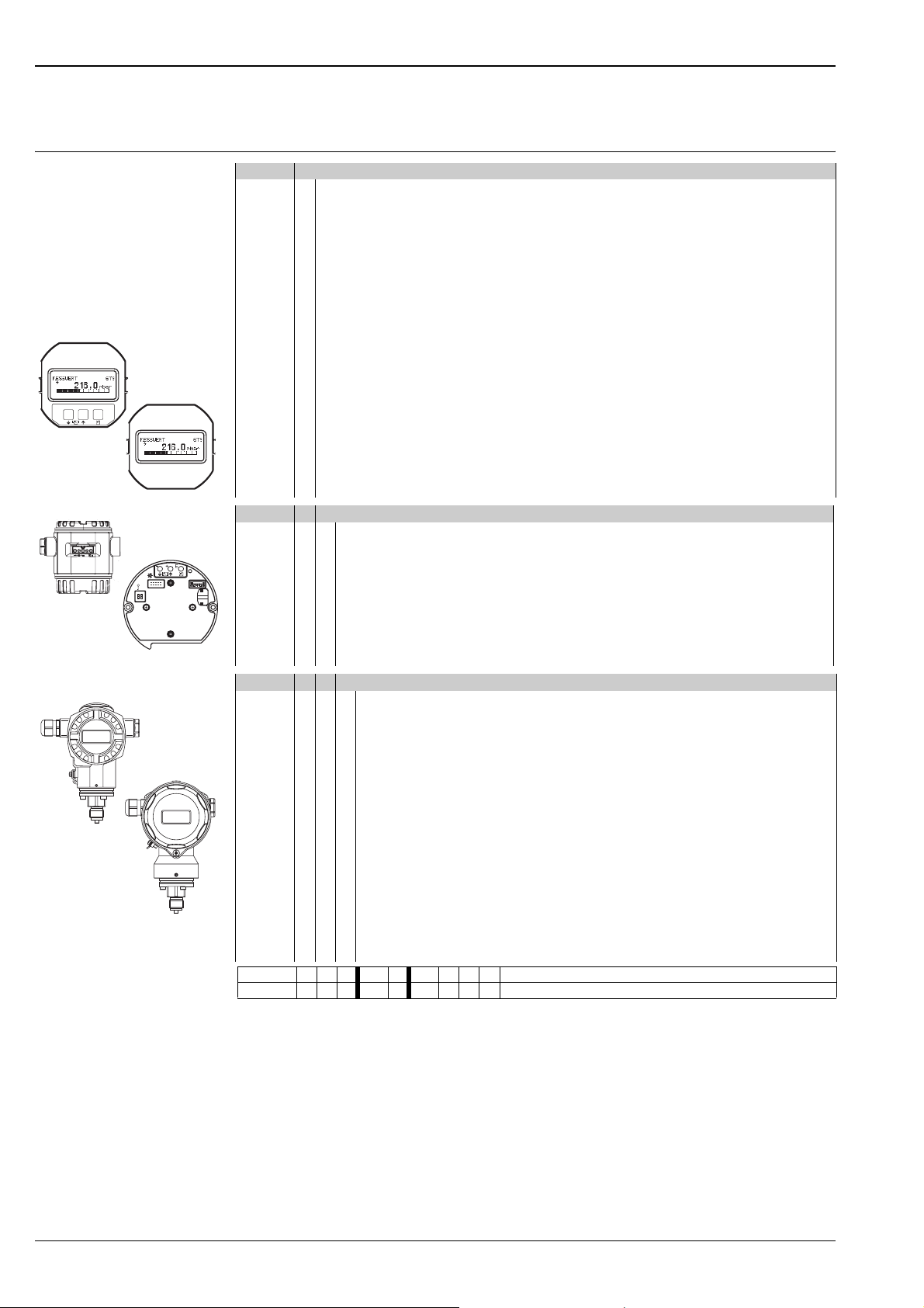
Ordering information
Cerabar S
PMC71
–
+
T14
10 Approval:
A For non-hazardous areas
1 ATEX II 1/2 G EEx ia IIC T6
6 ATEX II 1/2 G EEx ia IIC T6, overspill protection WHG
2 ATEX II 1/2 D EEx ia IIC T6
8 ATEX II 1 GD EEx ia IIC T6
3 ATEX II 1/2 GD EEx ia IIC T6
5 ATEX II 2 G EEx d[ia] IIC T6
7 ATEX II 3 G EEx nA II T6
S FM IS, Class I, II, III Division 1, Groups A – G; NI Class I Division 2, Groups A – D; AEx ia
T FM XP, Class I Division 1, Groups A – D; AEx d
➀
R FM NI, Class I, Division 2, Groups A – D
U CSA IS, Class I, II, III Division 1, Groups A – G; Class I Division 2, Groups A – D, Ex ia
V CSA XP, Class I Division 1, Groups B – D; Ex d
E
➁
G NEPSI Ex d[ia] IIC T4/T6
H NEPSI Ex ia IIC T6
I IECEx Zone 1 Ex ia IIC T6
KTIISEx ia IIC T6
L TIIS Ex d[ia] IIC T6
M TIIS Ex d[ia] IIC T4
NTIISEx ia IIC T4
20
➂
Output; Operation:
A 4...20 mA HART, operation outside, LCD (→ see Fig. ➀, o)
B 4...20 mA HART, operation inside, LCD (→ see Fig. ➀, p)
C 4...20 mA HART, operation inside (→ see Fig. p)
M PROFIBUS PA, operation outside, LCD (→ see Fig. n, o)
N PROFIBUS PA, operation inside, LCD (→ see Fig. n, p)
O PROFIBUS PA, operation inside (→ see Fig. p)
P FOUNDATION Fieldbus, operation outside, LCD (→ see Fig. n, p)
Display
➃
PC
ROM
Histo
]τ
[
ping
Dam
Sensor
on
21
off
Q FOUNDATION Fieldbus, operation inside, LCD (→ see Fig. n, p)
R FOUNDATION Fieldbus, operation inside (→ see Fig. p)
30 Housing; Cable entry; Protection:
A Aluminium T14 housing, optional display on the side, IP 66/67/NEMA 6P, Gland M 20x1,5
B Aluminium T14 housing, optional display on the side, IP 66/67/NEMA 6P, Thread G 1/2
C Aluminium T14 housing, optional display on the side, IP 66/67/NEMA 6P, Thread 1/2 NPT
D Aluminium T14 housing, optional display on the side, IP 66/67/NEMA 6P, M 12x1 PA plug
T17
E Aluminium T14 housing, optional display on the side, IP 66/67/NEMA 6P, 7/8" FF plug
F Aluminium T14 housing, optional display on the side, IP 65/NEMA 4X, Hand 7D plug 90°
1 AISI 316L T14 housing, optional display on the side, IP 66/67/NEMA 6P, Gland M 20x1,5
2 AISI 316L T14 housing, optional display on the side, IP 66/67/NEMA 6P, Thread G 1/2
3 AISI 316L T14 housing, optional display on the side, IP 66/67/NEMA 6P, Thread 1/2 NPT
4 AISI 316L T14 housing, optional display on the side, IP 66/67/NEMA 6P, M 12x1 PA plug
5 AISI 316L T14 housing, optional display on the side, IP 66/67/NEMA 6P, 7/8" FF plug
6 AISI 316L T14 housing, optional display on the side, IP 65/NEMA 4X, Hand 7D plug 90°
P AISI 316L T17 housing, optional display on the side, IP 66/68/NEMA 6P, Gland M 20x1,5
S AISI 316L T17 housing, optional display on the side, IP 66/68/NEMA 6P, Thread G 1/2
T AISI 316L T17 housing, optional display on the side, IP 66/68/NEMA 6P, Thread 1/2 NPT
U AISI 316L T17 housing, optional display on the side, IP 66/68/NEMA 6P, M 12x1 PA plug
V AISI 316L T17 housing, optional display on the side, IP 66/68/NEMA 6P, 7/8" FF plug
PMC71 order code
→ For continuation of ordering information for PMC71, see the following page.
70 Endress+Hauser
Page 71
Cerabar S
PMC71 (continued)
40 Sensor range; Sensor overload limit (= OPL):
Sensors for gauge pressure
Measurement limits: –100 % (–1 bar)...+100 % of sensor nominal range
Sensor nominal value (URL) OPL (Over pressure limit)
1C 100 mbar/10 kPa/1.5 psi g 4 bar/400 kPa/60 psi g
1E 250 mbar/25 kPa/3.75 psi g 5 bar/500 kPa/75 psi g
1F 400 mbar/40 kPa/6 psi g 8 bar/800 kPa/120 psi g
1H 1 bar/100 kPa/15 psi g 10 bar/1 MPa/150 psi g
1K 2 bar/200 kPa/30 psi g 18 bar/1,8 MPa/270 psi g
1M 4 bar/400 kPa/60 psi g 25 bar/2,5 MPa/375 psi g
1P 10 bar/1 MPa/150 psi g 40 bar/4 MPa/600 psi g
1S 40 bar/4 MPa/600 psi g 60 bar/6 MPa/900 psi g
Sensors for absolute pressure
Sensor nominal value (URL) OPL (Over pressure limit)
2C 100 mbar/10 kPa/1.5 psi abs 4 bar/400 kPa/60 psi abs
2E 250 mbar/25 kPa/3.75 psi abs 5 bar/500 kPa/75 psi abs
2F 400 mbar/40 kPa/6 psi abs 8 bar/800 kPa/120 psi abs
2H 1 bar/100 kPa/15 psi abs 10 bar/1 MPa/150 psi abs
2K 2 bar/200 kPa/30 psi abs 18 bar/1,8 MPa/270 psi abs
2M 4 bar/400 kPa/60 psi abs 25 bar/2,5 MPa/375 psi abs
2P 10 bar/1 MPa/150 psi abs 40 bar/4 MPa/600 psi abs
2S 40 bar/4 MPa/600 psi abs 60 bar/6 MPa/900 psi abs
50 Calibration; Unit:
1 Sensor range; mbar/bar
2 Sensor range; kPa/MPa
3 Sensor range; mmH
4 Sensor range; inH
6 Sensor range; psi
B Customised; see additional specification
C Factory certificate 5-point; see additional specification
D DKD certificate; see additional specification
K Platinum; see additional specification
L Platinum and factory certificate 5-point; see additional specification
M Platinum and DKD certificate; see additional specification
O/mH2O
2
O/ftH2O
2
70 Process connection; Material:
Thread, internal diaphragm
GA Thread ISO 228 G 1/2 A EN 837, AISI 316L
GB Thread ISO 228 G 1/2 A EN 837, Alloy C
GC Thread ISO 228 G 1/2 A EN 837, Monel
GD Thread ISO 228 G 1/2 A EN 837, PVDF
(max. 15 bar/225 psi, –10...+60°C/+14...+140°F)
GE Thread ISO 228 G 1/2 A G 1/4 (female), AISI 316L
GF Thread ISO 228 G 1/2 A G 1/4 (female), Alloy C
GG Thread ISO 228 G 1/2 A G 1/4 (female), Monel
GH Thread ISO 228 G 1/2 A hole 11.4 mm, AISI 316L
GJ Thread ISO 228 G 1/2 A hole 11.4 mm, Alloy C
GK Thread ISO 228 G 1/2 A hole 11.4 mm, Monel
RA Thread ANSI 1/2 MNPT 1/4 FNPT, AISI 316L (CRN)
RB Thread ANSI 1/2 MNPT 1/4 FNPT, Alloy C (CRN)
RC Thread ANSI 1/2 MNPT 1/4 FNPT, Monel
RD Thread ANSI 1/2 MNPT, hole 11.4 mm, AISI 316L (CRN)
RE Thread ANSI 1/2 MNPT, hole 11.4 mm, Alloy C (CRN)
RF Thread ANSI 1/2 MNPT, hole 11.4 mm, Monel
RG Thread ANSI 1/2 MNPT hole 3 mm, PVDF
(max. 15 bar/225 psi, –10...+60°C/+14...+140°F)
RH Thread ANSI 1/2 FNPT, AISI 316L (CRN)
RJ Thread ANSI 1/2 FNPT, Alloy C (CRN)
RK Thread ANSI 1/2 FNPT, Monel
GL Thread JIS B0202 G 1/2 (male), AISI 316L
RL Thread JIS B0203 R 1/2 (male), AISI 316L
GP Thread DIN 13 M 20x1.5 EN 837 hole 3 mm, AISI 316L
GQ Thread DIN 13 M 20x1.5 EN 837 hole 3 mm, Alloy C
For continuation "Process connection, Material" see next page.
PMC71 order code
→ For continuation of ordering information for PMC71, see the following page.
Endress+Hauser 71
Page 72
Cerabar S
PMC71 (continued)
70 Process connection; Material (continued):
Thread, flush-mounted diaphragm
1G Thread ISO 228 G 1 1/2 A, AISI 316L
1H Thread ISO 228 G 1 1/2 A, Alloy C
1J Thread ISO 228 G 1 1/2 A, Monel
1K Thread ISO 228 G 2 A, AISI 316L
1L Thread ISO 228 G 2 A, Alloy C
1M Thread ISO 228 G 2 A, Monel
2D Thread ANSI 1 1/2 MNPT, AISI 316L
2E Thread ANSI 1 1/2 MNPT, Alloy C
2F Thread ANSI 1 1/2 MNPT, Monel
2G Thread ANSI 2 MNPT, AISI 316L
2H Thread ANSI 2 MNPT, Alloy C
2J Thread ANSI 2 MNPT, Monel
1R Thread DIN 13 M 44x1.25, AISI 316L
1S Thread DIN 13 M 44x1.25, Alloy C
EN/DIN flanges, flush-mounted diaphragm
CP DN 32 PN 10-40 B1, AISI 316L
CQ DN 40 PN 10-40 B1, AISI 316L
BR DN 50 PN 10-16 A, PVDF (max. 15 bar/150 psi, –10...+60°C/+14...+140°F)
B3 DN 50 PN 10-40 B1, AISI 316L
C3 DN 50 PN 63 B2, AISI 316L
BS DN 80 PN 10-16 A, PVDF (max. 15 bar/150 psi, –10...+60°C/+14...+140°F)
B4 DN 80 PN 10-40 B1, AISI 316L
ANSI flanges, flush-mounted diaphragm
AE 1 1/2" 150 lbs RF, AISI 316/316L
AQ 1 1/2" 300 lbs RF, AISI 316/316L
AF 2" 150 lbs RF, AISI 316/316L
JR 2" 150 lbs RF, AISI 316L with ECTFE-coating
A3 2" 150 lbs RF, PVDF (max. 15 bar/225 psi, –10...+60°C/+14...+140°F)
AR 2" 300 lbs RF, AISI 316/316L
AG 3" 150 lbs RF, AISI 316/316L
JS 3" 150 lbs RF, AISI 316L with ECTFE-coating
A4 3" 150 lbs RF, PVDF (max. 15 bar/225 psi, –10...+60°C/+14...+140°F)
AS 3" 300 lbs RF, AISI 316/316L
AH 4" 150 lbs RF, AISI 316/316L
JT 4" 150 lbs RF, AISI 316L with ECTFE-coating
AT 4" 300 lbs RF, AISI 316/316L
JIS flanges, flush-mounted diaphragm
KF 10K 50A RF, AISI 316L
KL 10K 80A RF, AISI 316L
KH 10K 100A RF, AISI 316L
Hygienic connections, flush-mounted diaphragm
MP DIN 11851 DN 40 PN 25, AISI 316L, 3A with HNBR/EPDM seal
MR DIN 11851 DN 50 PN 25, AISI 316L, 3A with HNBR/EPDM seal
TD Tri-Clamp ISO 2852 DN 51 (2"), AISI 316L, 3A with HNBR/EPDM seal
TF Tri-Clamp ISO 2852 DN 76.1 (3"), AISI 316L, 3A with HNBR/EPDM seal
TK DRD 65 mm, PN 25, AISI 316L, 3A with HNBR/EPDM seal
TR Varivent type N for tubes DN 40 – DN 162, PN 40, AISI 316L,
3A with HNBR/EPDM seal
80 Seal:
A FKM Viton
BEPDM
DKalrez
EChemraz
F NBR/3A: HNBR (FDA)
1 FKM Viton, degreased
2 FKM Viton, cleaned for oxygen service
PMC71 order code
→ For continuation of ordering information for PMC71, see the following page.
72 Endress+Hauser
Page 73
Cerabar S
PMC71 (continued)
100 Additional option 1:
Anot selected
E SIL2/IEC 61508 Declaration of conformity
T High temperature version
B Material test certificate for wetted parts, inspection certificate as per EN 10204 3.1
acc. to specification 52005759
M Overvoltage protection
N HistoROM/M-DAT
S GL (German Lloyd)/ABS marine certificate
V Mounting on shut-off valve from above
2 Test report acc. to EN 10204 2.2
3 Routine test with certificate, inspection certificate as per EN 10204 3.1
4 Overpressure test with certificate,
inspection certificate as per EN 10204 3.1
110 Additional option 2:
Anot selected
E SIL2/IEC 61508 Declaration of conformity
T High temperature version
M Overvoltage protection
NHistoROM/M-DAT
S GL (German Lloyd)/ABS marine certificate
U Mounting bracket for wall/pipe, AISI 304
2 Test report acc. to EN 10204 2.2
3 Routine test with certificate, inspection certificate as per EN 10204 3.1
4 Overpressure test with certificate, inspection certificate as per EN 10204 3.1
5 Helium leak test EN 1518 with test certificate,
inspection certificate as per EN 10204 3.1
PMC71 complete order code
Endress+Hauser 73
Page 74
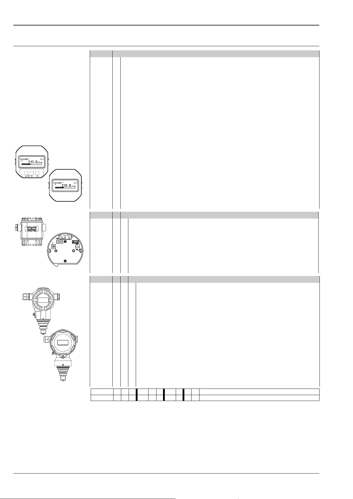
Cerabar S
PMP71
10
Approval:
A For non-hazardous areas
1 ATEX II 1/2 G EEx ia IIC T6
6 ATEX II 1/2 G EEx ia IIC T6, overspill protection WHG
2 ATEX II 1/2 D
4 ATEX II 1/3 D
8 ATEX II 1 GD EEx ia IIC T6
3 ATEX II 1/2 GD EEx ia IIC T6
5 ATEX II 2 G EEx d IIC T6
7 ATEX II 3 G EEx nA II T6
S FM IS, Class I, II, III Division 1, Groups A – G; NI Class I Division 2, Groups A – D; AEx ia
T FM XP, Class I Division 1, Groups A – D; AEx d
Q FM DIP, Class II, III Division 1, Groups E – G
R FM NI, Class I, Division 2, Groups A – D
U CSA IS, Class I, II, III Division 1, Groups A – G; Class I Division 2, Groups A – D, Ex ia
➀
V CSA XP, Class I Division 1, Groups B – D; Ex d
W CSA Class II, III Division 1, Groups E – G (Dust Ex)
G NEPSI Ex d IIC T6
H NEPSI Ex ia IIC T6
–
+
E
➁
I IECEx Zone 1 Ex ia IIC T6
KTIISEx ia IIC T6
L TIIS Ex d IIC T6
B Combined certificates: ATEX II 1/2 G EEx ia IIC T6 + II 2 G EEx d IIC T6
C Combined certificates: FM IS and XP Class I Division 1, Groups A – D
D Combined certificates: CSA IS and XP Class I Division 1, Groups A – D
E Combined certificates: FM/CSA IS and XP Class I Division 1, Groups A – D
20
➂
Output; Operation:
A 4...20 mA HART, operation outside, LCD (→ see Fig. ➀, o)
B 4...20 mA HART, operation inside, LCD (→ see Fig. ➀, p)
C 4...20 mA HART, operation inside (→ see Fig. p)
M PROFIBUS PA, operation outside, LCD (→ see Fig. n, o)
N PROFIBUS PA, operation inside, LCD (→ see Fig. n, p)
O PROFIBUS PA, operation inside (→ see Fig. p)
P FOUNDATION Fieldbus, operation outside, LCD (→ see Fig. n, p)
Display
➃
PC
ROM
Histo
]τ
[
ping
Dam
Sensor
on
21
off
Q FOUNDATION Fieldbus, operation inside, LCD (→ see Fig. n, p)
R FOUNDATION Fieldbus, operation inside (→ see Fig. p)
30 Housing; Cable entry; Protection:
T14
T17
A Aluminium T14 housing, optional display on the side, IP 66/67/NEMA 6P, Gland M 20x1.5
B Aluminium T14 housing, optional display on the side, IP 66/67/NEMA 6P, Thread G 1/2
C Aluminium T14 housing, optional display on the side, IP 66/67/NEMA 6P, Thread 1/2 NPT
D Aluminium T14 housing, optional display on the side, IP 66/67/NEMA 6P, M 12x1 PA plug
E Aluminium T14 housing, optional display on the side, IP 66/67/NEMA 6P, 7/8" FF plug
F Aluminium T14 housing, optional display on the side, IP 65/NEMA 4X, Hand 7D plug 90°
1 AISI 316L T14 housing, optional display on the side, IP 66/67/NEMA 6P, Gland M 20x1.5
2 AISI 316L T14 housing, optional display on the side, IP 66/67/NEMA 6P, Thread G 1/2
3 AISI 316L T14 housing, optional display on the side, IP 66/67/NEMA 6P, Thread 1/2 NPT
4 AISI 316L T14 housing, optional display on the side, IP 66/67/NEMA 6P, M 12x1 PA plug
5 AISI 316L T14 housing, optional display on the side, IP 66/67/NEMA 6P, 7/8" FF plug
6 AISI 316L T14 housing, optional display on the side, IP 65/NEMA 4X, Hand 7D plug 90°
R AISI 316L T17 housing, optional display on the side, IP 66/68/NEMA 6P, Gland M 20x1.5
S AISI 316L T17 housing, optional display on the side, IP 66/68/NEMA 6P, Thread G 1/2
T AISI 316L T17 housing, optional display on the side, IP 66/68/NEMA 6P, Thread 1/2 NPT
U AISI 316L T17 housing, optional display on the side, IP 66/68/NEMA 6P, M 12x1 PA plug
V AISI 316L T17 housing, optional display on the side, IP 66/68/NEMA 6P, 7/8" FF plug
PMP71 order code
→ For continuation of ordering information for PMP71, see the following page.
74 Endress+Hauser
Page 75
Cerabar S
PMP71 (continued)
40 Sensor range; Sensor overload limit (= OPL):
Sensors for gauge pressure
Measurement limits: –100 % (–1 bar)...+100 % of sensor nominal range
Sensor nominal value (URL) OPL (Over pressure limit)
1C 100 mbar/10 kPa/1.5 psi g 4 bar/400 kPa/60 psi g
1E 250 mbar/25 kPa/3.75 psi g 4 bar/400 kPa/60 psi g
1F 400 mbar/40 kPa/6 psi g 6 bar/600 kPa/90 psi g
1H 1 bar/100 kPa/15 psi g 10 bar/1 MPa/150 psi g
1K 2 bar/200 kPa/30 psi g 20 bar/2 MPa/300 psi g
1M 4 bar/400 kPa/60 psi g 28 bar/2.8 MPa/420 psi g
1P 10 bar/1 MPa/150 psi g 40 bar/4 MPa/600 psi g
1S 40 bar/4 MPa/600 psi g 160 bar/16 MPa/2400 psi g
1U 100 bar/10 MPa/1500 psi g 400 bar/40 MPa/6000 psi g
1W 400 bar/40 MPa/6000 psi g 600 bar/60 MPa/9000 psi g
1X 700 bar/70 MPa/10500 psi g 1050 bar/105 MPa/15700 psi g
Sensors for absolute pressure
Sensor nominal value (URL) OPL (Over pressure limit)
2C 100 mbar/10 kPa/1.5 psi abs 4 bar/400 kPa/60 psi abs
2E 250 mbar/25 kPa/3.75 psi abs 4 bar/400 kPa/60 psi abs
2F 400 mbar/40 kPa/6 psi abs 6 bar/600 kPa/90 psi abs
2H 1 bar/100 kPa/15 psi abs 10 bar/1 MPa/150 psi abs
2K 2 bar/200 kPa/30 psi abs 20 bar/2 MPa/300 psi abs
2M 4 bar/400 kPa/60 psi abs 28 bar/2.8 MPa/420 psi abs
2P 10 bar/1 MPa/150 psi abs 40 bar/4 MPa/600 psi abs
2S 40 bar/4 MPa/600 psi abs 160 bar/16 MPa/2400 psi abs
2U 100 bar/10 MPa/1500 psi g 400 bar/40 MPa/6000 psi g
2W 400 bar/40 MPa/6000 psi g 600 bar/60 MPa/9000 psi g
2X 700 bar/70 MPa/10500 psi g 1050 bar/105 MPa/15700 psi g
50 Calibration; Unit:
1 Sensor range; mbar/bar
2 Sensor range; kPa/MPa
3 Sensor range; mmH
4 Sensor range; inH
6 Sensor range; psi
B Customised; see additional specification
C Factory certificate 5-point; see additional specification
D DKD certificate; see additional specification
K Platinum; see additional specification
L Platinum and factory certificate 5-point; see additional specification
M Platinum and DKD certificate; see additional specification
O/mH2O
2
O/ftH2O
2
60 Membrane material:
1 AISI 316L
2Alloy C276
6 AISI 316L with Gold-Rhodium coating
70 Process connection; Material:
Thread, internal diaphragm
GA Thread ISO 228 G 1/2 A EN 837, AISI 316L
GB Thread ISO 228 G 1/2 A EN 837, Alloy C
GE Thread ISO 228 G 1/2 A G 1/4 (female), AISI 316L
GF Thread ISO 228 G 1/2 A G 1/4 (female), Alloy C
GH Thread ISO 228 G 1/2 A hole 11.4 mm, AISI 316L
GJ Thread ISO 228 G 1/2 A hole 11.4 mm, Alloy C
RA Thread ANSI 1/2 MNPT 1/4 FNPT, AISI 316L (CRN)
RB Thread ANSI 1/2 MNPT 1/4 FNPT, Alloy C (CRN)
RD Thread ANSI 1/2 MNPT hole 11.4 mm, AISI 316L (CRN)
RE Thread ANSI 1/2 MNPT hole 11.4 mm, Alloy C (CRN)
RH Thread ANSI 1/2 FNPT, AISI 316L
RJ Thread ANSI 1/2 FNPT, Alloy C
GL Thread JIS B0202 G 1/2 (male), AISI 316L
RL Thread JIS B0203 R 1/2 (male), AISI 316L
For continuation "Process connection; Material", see next page.
PMP71 order code
→ For continuation of ordering information for PMP71, see the following page.
Endress+Hauser 75
Page 76
Cerabar S
PMP71 (continued)
70 Process connection; Material (continued):
Thread, internal diaphragm (continued)
GP Thread DIN 13 M 20x1.5 EN 837 hole 11.4 mm, AISI 316L
GQ Thread DIN 13 M 20x1.5 EN 837 hole 11.4 mm, Alloy C
Thread, flush-mounted diaphragm
1A Thread ISO 228 G 1/2 A, DIN 3852, AISI 316L
1B Thread ISO 228 G 1/2 A, DIN 3852, Alloy C
1D Thread ISO 228 G 1 A, AISI 316L
1E Thread ISO 228 G 1 A, Alloy C
1G Thread ISO 228 G 1 1/2 A, AISI 316L
1H Thread ISO 228 G 1 1/2 A, Alloy C
1K Thread ISO 228 G 2 A, AISI 316L
1L Thread ISO 228 G 2 A, Alloy C
2A Thread ANSI 1 MNPT, AISI 316L (CRN)
2B Thread ANSI 1 MNPT, Alloy C (CRN)
2D Thread ANSI 1 1/2 MNPT, AISI 316L (CRN)
2E Thread ANSI 1 1/2 MNPT, Alloy C (CRN)
2G Thread ANSI 2 MNPT, AISI 316L (CRN)
2H Thread ANSI 2 MNPT, Alloy C
1N Thread DIN 16288 M 20x1.5, AISI 316L
1P Thread DIN 16288 M 20x1.5, Alloy C
1R Thread DIN 13 M 44x1.25, AISI 316L
1S Thread DIN 13 M 44x1.25, Alloy C
EN/DIN flanges, flush-mounted diaphragm
CN DN 25 PN 10-40 B1, AISI 316L
CP DN 32 PN 10-40 B1, AISI 316L
CQ DN 40 PN 10-40 B1, AISI 316L
B3 DN 50 PN 10-40 B1, AISI 316L
B4 DN 80 PN 10-40 B1, AISI 316L
ANSI flanges, flush-mounted diaphragm
AN 1" 300 lbs RF, AISI 316/316L (CRN)
AE 1 1/2" 150 lbs RF, AISI 316/316L (CRN)
AQ 1 1/2" 300 lbs RF, AISI 316/316L (CRN)
AF 2" 150 lbs RF, AISI 316/316L (CRN)
AR 2" 300 lbs RF, AISI 316/316L (CRN)
AG 3" 150 lbs RF, AISI 316/316L (CRN)
AS 3" 300 lbs RF, AISI 316/316L (CRN)
AH 4" 150 lbs RF, AISI 316/316L (CRN)
AT 4" 300 lbs RF, AISI 316/316L (CRN)
JIS flanges, flush-mounted diaphragm
KA 20K 25A RF, AISI 316L
KF 10K 50A RF, AISI 316L
KL 10K 80A RF, AISI 316L
KH 10K 100A RF, AISI 316L
Other
UR Ovalflange adapter 1/4-18 NPT, mounting: 7/16-20 UNF, AISI 316L
U1 Prepared for diaphragm seal mount, AISI 316L
90 Fill fluid:
A Silicone oil fill
F Inert oil fill
K Inert oil fill, degreased
N Inert oil fill, cleaned for oxygen services
PMP71 order code
→ For continuation of ordering information for PMP71, see the following page.
76 Endress+Hauser
Page 77
Cerabar S
PMP71 (continued)
100 Additional option 1:
Anot selected
E SIL2/IEC 61508 Declaration of conformity
B Material test certificate for wetted parts, inspection certificate as per
EN 10204 3.1 acc. to specification 52005759
C NACE MR0175 (wetted parts)
D Material test certificate for wetted parts as per EN 10204 3.1 and NACE
MR0175 material, inspection certificate as per EN 10204 acc. to specification
52010806
M Overvoltage protection
NHistoROM/M-DAT
S GL (German Lloyd)/ABS marine certificate
2 Test report acc. to EN10204 2.2
3 Routine test with certificate, inspection certificate as per EN 10204 3.1
4 Overpressure test with certificate, inspection certificate as per EN 10204 3.1
110 Additional option 2:
Anot selected
E SIL2/IEC 61508 Declaration of conformity
M Overvoltage protection
N HistoROM/M-DAT
S GL (German Lloyd)/ABS marine certificate
U Mounting bracket for wall/pipe, AISI 304
2 Test report acc. to EN10204 2.2
3 Routine test with certificate, inspection certificate as per EN 10204 3.1
4 Overpressure test with certificate, inspection certificate as per EN 10204
3.1
5 Helium leak test EN 1528 with test certificate, inspection certificate as
per EN 10204 3.1
PMP71 complete order code
Endress+Hauser 77
Page 78
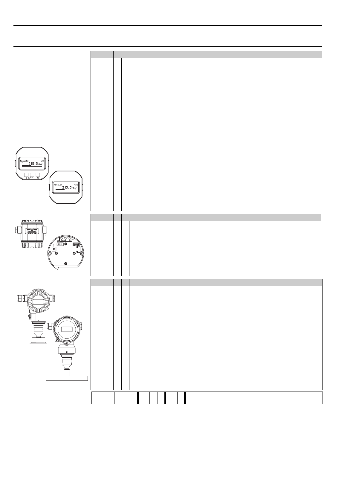
Cerabar S
PMP75
10 Approval
:
A For non-hazardous areas
1 ATEX II 1/2 G EEx ia IIC T6
6 ATEX II 1/2 G EEx ia IIC T6, overspill protection WHG
2 ATEX II 1/2 D
4 ATEX II 1/3 D
8 ATEX II 1 GD EEx ia IIC T6
3 ATEX II 1/2 GD EEx ia IIC T6
5 ATEX II 2 G EEx d IIC T6
7 ATEX II 3 G EEx nA II T6
S FM IS, Class I, II, III Division 1, Groups A – G; NI Class I Division 2, Groups A – D; AEx ia
T FM XP, Class I Division 1, Groups A – D; AEx d
Q FM DIP, Class II, III Division 1, Groups E – G
R FM NI, Class I, Division 2, Groups A – D
U CSA IS, Class I, II, III Division 1, Groups A – G; Class I Division 2, Groups A – D, Ex ia
➀
V CSA XP, Class I Division 1, Groups B – D; Ex d
W CSA Class II, III Division 1, Groups E – G (Dust Ex)
G NEPSI Ex d IIC T6
H NEPSI Ex ia IIC T6
–
+
E
➁
I IECEx Zone 1Ex ia IIC T6
KTIISEx ia IIC T6
L TIIS Ex d IIC T6
B Combined certificates: ATEX II 1/2 G EEx ia IIC T6 + II 2 G EEx d IIC T6
C Combined certificates: FM IS and XP Class I Division 1, Groups A – D
D Combined certificates: CSA IS and XP Class I Division 1, Groups A – D
E Combined certificates: FM/CSA IS and XP Class I Division 1, Groups A – D
20
➂
Output; Operation:
A 4...20 mA HART, operation outside, LCD (→ see Fig. ➀, o)
B 4...20 mA HART, operation inside, LCD (→ see Fig. ➀, p)
C 4...20 mA HART, operation inside (→ see Fig. p)
M PROFIBUS PA, operation outside, LCD (→ see Fig. n, o)
N PROFIBUS PA, operation inside, LCD (→ see Fig. n, p)
O PROFIBUS PA, operation inside (→ see Fig. p)
P FOUNDATION Fieldbus, operation outside, LCD (→ see Fig. n, p)
Display
➃
PC
ROM
Histo
]τ
[
ping
Dam
Sensor
on
21
off
Q FOUNDATION Fieldbus, operation inside, LCD (→ see Fig. n, p)
R FOUNDATION Fieldbus, operation inside (→ see Fig. p)
T14
30 Housing; Cable entry; Protection:
A Aluminium T14 housing, optional display on the side, IP 66/67/NEMA 6P, Gland M 20x1.5
B Aluminium T14 housing, optional display on the side, IP 66/67/NEMA 6P, Thread G 1/2
C Aluminium T14 housing, optional display on the side, IP 66/67/NEMA 6P, Thread 1/2 NPT
D Aluminium T14 housing, optional display on the side, IP 66/67/NEMA 6P, M 12x1 PA plug,
T17
E Aluminium T14 housing, optional display on the side, IP 66/67/NEMA 6P, 7/8" FF plug
F Aluminium T14 housing, optional display on the side, IP 65/NEMA 4X, Hand 7D plug 90°
1 AISI 316L T14 housing, optional display on the side, IP 66/67/NEMA 6P, Gland M 20x1.5
2 AISI 316L T14 housing, optional display on the side, IP 66/67/NEMA 6P, Thread G 1/2
3 AISI 316L T14 housing, optional display on the side, IP 66/67/NEMA 6P, Thread 1/2 NPT
4 AISI 316L T14 housing, optional display on the side, IP 66/67/NEMA 6P, M 12x1 PA plug
5 AISI 316L T14 housing, optional display on the side, IP 66/67/NEMA 6P, 7/8" FF plug
6 AISI 316L T14 housing, optional display on the side, IP 65/NEMA 4X, Hand 7D plug 90°
R AISI 316L T17 housing, optional display on the side, IP 66/68/NEMA 6P, Gland M 20x1.5
S AISI 316L T17 housing, optional display on the side, IP 66/68/NEMA 6P, Thread G 1/2
T AISI 316L T17 housing, optional display on the side, IP 66/68/NEMA 6P, Thread 1/2 NPT
U AISI 316L T17 housing, optional display on the side, IP 66/68/NEMA 6P, M 12x1 PA plug
V AISI 316L T17 housing, optional display on the side, IP 66/68/NEMA 6P, 7/8" FF plug
PMP75 order code
→ For continuation of ordering information for PMP75, see the following page.
78 Endress+Hauser
Page 79
Cerabar S
PMP75 (continued)
40 Sensor range; Sensor overload (= OPL):
Sensors for gauge pressure
Measurement limits: –100 % (–1 bar)...+100 % of sensor nominal range
Sensor nominal value (URL) OPL (Over pressure limit)
1F 400 mbar/40 kPa/6 psi g 6 bar/600 kPa/90 psi g
1H 1 bar/100 kPa/15 psi g 10 bar/1 MPa/150 psi g
1K 2 bar/200 kPa/30 psi g 20 bar/2 MPa/300 psi g
1M 4 bar/400 kPa/60 psi g 28 bar/2.8 MPa/420 psi g
1P 10 bar/1 MPa/150 psi g 40 bar/4 MPa/600 psi g
1S 40 bar/4 MPa/600 psi g 160 bar/16 MPa/2400 psi g
1U 100 bar/10 MPa/1500 psi g 400 bar/40 MPa/6000 psi g
1W 400 bar/40 MPa/6000 psi g 600 bar/60 MPa/9000 psi g
1X 700 bar/70 MPa/10500 psi g 1050 bar/105 MPa/15700 psi g
Sensors for absolute pressure
Sensor nominal value (URL) OPL (Over pressure limit)
2F 400 mbar/40 kPa/6 psi abs 6 bar/600 kPa/90 psi abs
2H 1 bar/100 kPa/15 psi abs 10 bar/1 MPa/150 psi abs
2K 2 bar/200 kPa/30 psi abs 20 bar/2 MPa/300 psi abs
2M 4 bar/400 kPa/60 psi abs 28 bar/2.8 MPa/420 psi abs
2P 10 bar/1 MPa/150 psi abs 40 bar/4 MPa/600 psi abs
2S 40 bar/4 MPa/600 psi abs 160 bar/16 MPa/2400 psi abs
2U 100 bar/10 MPa/1500 psi abs 400 bar/40 MPa/6000 psi abs
2W 400 bar/40 MPa/6000 psi abs 600 bar/60 MPa/9000 psi abs
2X 700 bar/70 MPa/10500 psi abs 1050 bar/105 MPa/15700 psi abs
50 Calibration; Unit:
1 Sensor range; mbar/bar
2 Sensor range; kPa/MPa
3 Sensor range; mmH
4 Sensor range; inH
6 Sensor range; psi
B Customised; see additional specification
C Factory certificate 5-point; see additional specification
D DKD calibration: see additional specification
O/mH2O
2
O/ftH2O
2
60 Membrane material:
1 AISI 316L
2Alloy C276
3Monel
5Tantal
6 AISI 316L with Gold-Rhodium coating
7 AISI 316L with 0.09 mm PTFE foil (not for vacuum applications)
8 AISI 316L with 0.25 mm PTFE foil (not for vacuum applications, only for non-hazardous areas)
70 Process connection, Material:
Thread, flush-mounted diaphragm
1D Thread ISO 228 G 1 A, AISI 316L
1E Thread ISO 228 G 1 A, Alloy C
1G Thread ISO 228 G 1 1/2 A, AISI 316L
1H Thread ISO 228 G 1 1/2 A, Alloy C
1K Thread ISO 228 G 2 A, AISI 316L
1L Thread ISO 228 G 2 A, Alloy C
2A Thread ANSI 1 MNPT, AISI 316L
2D Thread ANSI 1 1/2 MNPT, AISI 316L
2G Thread ANSI 2 MNPT, AISI 316L
Clamp connections
TB Tri-Clamp, ISO 2852 DN 25 (1"), DIN 32676 DN 25, AISI 316L
TC Tri-Clamp, ISO 2852 DN 38 (1 1/2"), DIN 32676 DN 40, AISI 316L
TD Tri-Clamp, ISO 2852 DN 40 – DN 51 (2")/DN 50, AISI 316L
TF Tri-Clamp, ISO 2852 DN 70 – DN 76.1 (3"), AISI 316L
PMP75 order code
→ For continuation of ordering information for PMP75, see the following page.
Endress+Hauser 79
Page 80
Cerabar S
PMP75 (continued)
70 Process connection; Material (continued):
Pipe diaphragm seal, Clamp
SB Tri-Clamp, ISO 2852 DN 25 (1"), AISI 316L
SC Tri-Clamp, ISO 2852 DN 38 (1 1/2"), AISI 316L, 3.1 +
Pressure test acc. to PED Cat.II
SD Tri-Clamp, ISO 2852 DN 51 (2"), AISI 316L, 3.1 + Pressure test acc. to PED Cat.II
Hygienic connections
TR Varivent type N for pipes DN 40 – DN 162, PN 40, AISI 316L
TK DRD 65 mm, PN 25, AISI 316L
MR DIN 11851 DN 50 PN 25, AISI 316L
MS DIN 11851 DN 65 PN 25, AISI 316L
MT DIN 11851 DN 80 PN 25, AISI 316L
M3 DIN 11851 DN 50 PN 25 thread, AISI 316L
M4 DIN 11851 DN 65 PN 25 thread, AISI 316L
M5 DIN 11851 DN 80 PN 25 thread, AISI 316L
TG SMS 1" PN 25, AISI 316L
TH SMS 1 1/2" PN 25, AISI 316L
TI SMS 2" PN 25, AISI 316L
TL APV-RJT 1" PN 40, AISI 316L
TM APV-RJT 1 1/2" PN 40, AISI 316L
TN APV-RJT 2" PN 40, AISI 316L
TP APV-ISS 1" PN 40, AISI 316L
TQ APV-ISS 1 1/2" PN 40, AISI 316L
TS APV-ISS 2" PN 40, AISI 316L
TK DRD 65 mm PN 25, AISI 316L
TR Varivent Type N for pipes DN 40 – DN 162 PN 40, AISI 316L
EN/DIN flanges, flush-mounted diaphragm
CN DN 25 PN 10-40 B1, AISI 316L
DN DN 25 PN 63-160 E, AISI 316L
EN DN 25 PN 250 E, AISI 316L
E1 DN 25 PN 400 E, AISI 316L
CP DN 32 PN 10-40 B1, AISI 316L
CQ DN 40 PN 10-40 B1, AISI 316L
B3 DN 50 PN 10-40 B1, AISI 316L
C3 DN 50 PN 63 B2, AISI 316L 2
EF DN 50 PN 100-160 E, AISI 316L
ER DN 50 PN 250 E, AISI 316L
E3 DN 50 PN 400 E, AISI 316L
B4 DN 80 PN 10-40 B1, AISI 316L
C4 DN 80 PN 100 B2, AISI 316L
C5 DN 100 PN 100 B2, AISI 316L
EN/DIN flanges with extended diaphragm seal, flush-mounted diaphragm
D3 DN 50 PN 10-40 B1, Tubus 50 mm/100 mm/200 mm, AISI 316L
D4 DN 80 PN 10-40 B1, Tubus 50 mm/100 mm/200 mm, AISI 316L
ANSI flanges, flush-mounted diaphragm
AC 1" 150 lbs RF, AISI 316/316L (CRN)
AN 1" 300 lbs RF, AISI 316/316L (CRN)
HC 1" 400/600 lbs RF, AISI 316/316L (CRN)
HN 1" 900/1500 lbs RF, AISI 316/316L (CRN)
H0 1" 2500 lbs RF, AISI 316/316L (CRN)
AE 1 1/2" 150 lbs RF, AISI 316/316L (CRN)
AQ 1 1/2" 300 lbs RF, AISI 316/316L (CRN)
AF 2" 150 lbs RF, AISI 316/316L (CRN)
AR 2" 300 lbs RF, AISI 316/316L (CRN)
HF 2" 400/600 lbs RF, AISI 316/316L (CRN)
HR 2" 900/1500 lbs RF, AISI 316/316L (CRN)
H3 2" 2500 lbs RF, AISI 316/316L (CRN)
AG 3" 150 lbs RF, AISI 316/316L (CRN)
AS 3" 300 lbs RF, AISI 316/316L (CRN)
AH 4" 150 lbs RF, AISI 316/316L (CRN)
AT 4" 300 lbs RF, AISI 316/316L (CRN)
PMP75 order code
→ For continuation of ordering information for PMP75, see the following page.
80 Endress+Hauser
Page 81
Cerabar S
PMP75 (continued)
70 Process connection; Material (continued):
ANSI flanges with extended diaphragm seal
J3 2" 150 lbs RF, Tubus 2"/4"/6"/8", AISI 316/316L
J4 3" 150 lbs RF, Tubus 2"/4"/6"/8", AISI 316/316L
J7 3" 300 lbs RF, Tubus 2"/4"/6"/8", AISI 316/316L
J5 4" 150 lbs RF, Tubus 2"/4"/6"/8", AISI 316/316L
J8 4" 300 lbs RF, Tubus 2"/4"/6"/8", AISI 316/316L
JIS flanges, flush-mounted diaphragm
KA 10K 25A RF, AISI 316L
KF 10K 50A RF, AISI 316L
KL 10K 80A RF, AISI 316L
KH 10K 100A RF, AISI 316L
Other
UA Separator ISO 228 G 1/2 A PN 160, EN 837, welded, AISI 316L
UB Separator ANSI 1/2 MNPT, PN 160, welded, AISI 316L
UC Separator ISO 228 G 1/2 B PN 400, EN 837, screwed, AISI 316L
UD Separator ANSI 1/2 MNPT PN 400, screwed, AISI 316L
UG 1/2 NPT Off line thread, bolted, AISI 316L
UH 1 NPT Off line thread, bolted, AISI 316L
90 Fill fluid:
A Silicone oil
D Vegetable oil
FInert oil
G High temperature oil and extension 100 mm
H Silicone oil and extension 100 mm
N Inert oil, cleaned for oxygen services
1 ... m capillary, silicone oil
2 ... ft capillary, silicone oil
3 ... m capillary, high temperature oil
4 ... ft capillary, high temperature oil
5 ... m capillary, vegetable oil
4 ... ft capillary, vegetable oil
100 Additional option 1:
Anot selected
E SIL2/IEC 61508 Declaration of conformity
B Material test certificate for wetted parts, inspection certificate as per EN
10204 3.1 acc. to specification 52005759
C NACE MR0175 (wetted parts)
D Material test certificate for wetted parts, inspection certificate as per EN
10204 3.1 and NACE MR0175 material, inspection certificate as per
EN 10204 acc. to specification 52010806
M Overvoltage protection
NHistoROM/M-DAT
S GL (German Lloyd)/ABS marine certificate
2 Test report acc. to EN 10204 2.2
3 Routine test with certificate, inspection certificate as per EN 10204 3.1
4 Overpressure test with certificate, inspection certificate as per EN 10204 3.1
110 Additional option 2:
Anot selected
E SIL2/IEC 61508 Declaration of conformity
M Overvoltage protection
N HistoROM/M-DAT
B EN10204-3.1 material, Ra < 0.4 µm/15.75 µin (180 grit),
electropolished, (wetted) inspection certificate (in conjunction with
process connection versions "TC", "TD" and "TR")
S GL (German Lloyd)/ABS marine certificate
U Mounting bracket for wall/pipe, AISI 304
2 Test report acc. to EN 10204 2.2
3 Routine test with certificate, inspection certificate as per EN 10204 3.1
4 Overpressure test with certificate,
inspection certificate as per EN 10204 3.1
PMP75 complete order code
Endress+Hauser 81
Page 82

Cerabar S
Documentation
Innovation • For process pressure, differential pressure, flow and level measurement: IN001P/00/en
Field of Activities • Pressure measurement, Powerful instruments for process pressure, differential pressure, level and flow:
FA004P/00/en
Technical Information • Deltabar S: TI382P/00/en
• EMC test basic principles TI241F/00/en
Operating Instructions 4...20 mA HART:
• Cerabar S: BA271P/00/de
• Description of device functions Cerabar S/Deltabar S, Pressure and Differential pressure transmitters:
BA274P/00/en
PROFIBUS PA:
• Cerabar S: BA295P/00/de
• Description of device functions Cerabar S/Deltabar S, Pressure and Differential pressure transmitters:
BA296P/00/en
FOUNDATION Fieldbus:
• Cerabar S: BA302P/00/de
• Description of device functions Cerabar S/Deltabar S, Pressure and Differential pressure transmitters:
BA303P/00/en
Manual for Functional Safety (SIL)
Safety Instructions
• Cerabar S (4...20 mA): SD190P/00/en
Certificate/Type of
Protection
ATEX II 1 G EEx ia IIC T6 PMC71, PMP71,
ATEX II 1/2 D PMP71, PMP72,
ATEX II 1/2 D EEx ia IIC T6 PMC71 – 4...20 mA HART
ATEX II 1/3 D PMP71, PMP72,
ATEX II 2 G EEx d IIC T6 PMP71, PMP72,
ATEX II 2 G EEx d[ia] IIC T6 PMC71 – 4...20 mA HART,
ATEX II 3 G EEx nA II T6 PMC71, PMP71,
ATEX II 1/2 GD
EEx ia IIC T6
ATEX II 1 GD EEx ia IIC T6 PMC71, PMP71,
ATEX II 1/2 G EEx ia IIC T6
+ ATEX II 2 G EEx d IIC T6
Device Electronic insert Documentation
– 4...20 mA HART,
PMP72, PMP75
PMP75
PMP75
PMP75
PMP72, PMP75
PMC71, PMP71,
PMP72, PMP75
PMP72, PMP75
PMP71, PMP75 – 4...20 mA HART,
PROFIBUS PA,
FOUNDATION Fieldbus
– 4...20 mA HART
– PROFIBUS PA,
FOUNDATION Fieldbus
– PROFIBUS PA,
FOUNDATION Fieldbus
– 4...20 mA HART
– PROFIBUS PA,
FOUNDATION Fieldbus
– 4...20 mA HART,
PROFIBUS PA,
FOUNDATION Fieldbus
PROFIBUS PA.,
FOUNDATION Fieldbus
– 4...20 mA HART,
PROFIBUS PA,
FOUNDATION Fieldbus
– 4...20 mA HART,
PROFIBUS PA,
FOUNDATION Fieldbus
– 4...20 mA HART,
PROFIBUS PA,
FOUNDATION Fieldbus
PROFIBUS PA,
FOUNDATION Fieldbus
– XA244P
– XA246P
– XA289P
– XA247P
– XA290P
– XA248P
– XA291P
– XA249P
– XA250P
– XA251P
– XA253P
– XA276P
– XA252P
82 Endress+Hauser
Page 83

Cerabar S
Installation/ Control Drawings
Certificate/Type of
Protection
IECEx Zone 1 Ex ia IIC T6 PMC71, PMP71,
Certificate/Type of
Protection
NEPSI Ex ia IIC T6 PMC71, PMP71,
NEPSI Ex d IIC T6 PMP71, PMP72,
NEPSI Ex d[ia] IIC T6 PMC71 – 4...20 mA HART,
Certificate/Type of
Protection
FM IS Class I, II, III,
Division 1, Groups A – G;
NI, Class I Division 2,
Groups A – D; AEx ia
CSA IS Class I, II, III,
Division 1, Groups A – G;
Class I Division 2,
Groups A – G
FM IS + XP Class I,
Division 1, Groups A – D
CSA IS + XP Class I,
Division 1, Groups A – D
FM/CSA IS + XP Class I,
Division 1, Groups A – D
Device Electronic insert Documentation
– 4...20 mA HART – XB005P
PMP75
Device Electronic insert Documentation
PMP72, PMP75
PMP75
Device Electronic insert Documentation
PMC71, PMP71,
PMP72, PMP75
PMC71, PMP71,
PMP72, PMP75
PMP71, PMP72,
PMP75
PMP71, PMP72,
PMP75
PMP71, PMP72,
PMP75
– 4...20 mA HART,
PROFIBUS PA,
FOUNDATION Fieldbus
– 4...20 mA HART,
PROFIBUS PA,
FOUNDATION Fieldbus
PROFIBUS PA,
FOUNDATION Fieldbus
– 4...20 mA HART
– PROFIBUS PA,
FOUNDATION Fieldbus
– 4...20 mA HART
– PROFIBUS PA,
FOUNDATION Fieldbus
– 4...20 mA HART
– PROFIBUS PA,
FOUNDATION Fieldbus
– 4...20 mA HART
– PROFIBUS PA,
FOUNDATION Fieldbus
– 4...20 mA HART
– PROFIBUS PA,
FOUNDATION Fieldbus
– XC003P
– XC005P
– XC005P
–ZD147P
–ZD188P
–ZD148P
–ZD189P
–ZD187P
–ZD190P
–ZD154P
–ZD191P
– ZD154P + ZD187P
– ZD190P + ZD191P
Overspill protection • WHG: ZE260P/00/de
Endress+Hauser 83
Page 84

Cerabar S
International Head Quarter
Endress+Hauser
GmbH+Co. KG
Instruments International
Colmarer Str. 6
79576 Weil am Rhein
Deutschland
Tel. +49 76 21 9 75 02
Fax +49 76 21 9 75 34 5
www.endress.com
[email protected]
TI383P/00/en/03.06
CCS/FM+SGML 6.0
 Loading...