

Endress+Hauser Cerabar S PMP71 Operating Instructions Manual
Operating Instructions
Cerabar S PMP71 with MID Part Certificate
Process pressure measurement
BA00412P/00/EN/02.12
71185804
Valid for software version:
02.10.54

Overview of documentation Cerabar S PMP71 with 4 to 20 mA HART
Overview of documentation
Device Documentation Content Remarks
Cerabar S 4 to 20 mA HART
Technical Information TI00383P Technical data
Operating Instructions BA00412P – Identification
Operating Instructions BA00413P – Examples of configuration for
Brief Operating Instructions KA01095P
Brief Operating Instructions KA00298P
Safety Manual SD00190P
Functional Safety Manual
– Installation
– Wiring
–Operation
– Commissioning, Description of Quick Setup menus
– Maintenance
– Troubleshooting and spare parts
– Appendix: Illustration of menus
pressure measurement
– Description of parameters
– Troubleshooting
– Appendix: Illustration of menus
– Installation
– Wiring
– Onsite operation
– Commissioning
– Description of Quick Setup menus
– Wiring
– Operation without onsite
display
– Description of Quick Setup menus
–HistoROM
– Safety function with Cerabar S
– Behavior during operation and in event of failure
– Commissioning and iterative tests
–Settings
– Safety-specific characteristic quantities
– Management summary
®
/M-DAT operation
– The documentation can be found on the CD
supplied.
– The documentation is also available
via the Internet. See:
www.endress.com → Download
– The documentation is supplied with the device.
– The documentation can also be found on the
CD supplied.
– The documentation is also available
via the Internet. See:
www.endress.com → Download
– The documentation is supplied with the device.
See connection compartment cover.
– The documentation can also be found on the
CD supplied.
– The documentation is valid for devices showing
version "E" in feature 100 "Additional options
1" or in feature 110 "Additional options 2". See
also Technical Information TI00383P, Section
"Ordering information".
2 Endress+Hauser

Cerabar S PMP71 with 4 to 20 mA HART Table of contents
Table of contents
1 Safety instructions . . . . . . . . . . . . . . . . 4
1.1 Designated use . . . . . . . . . . . . . . . . . . . . . . . . . . . . 4
1.2 Installation, commissioning and operation . . . . . . . . 4
1.3 Operational and process safety . . . . . . . . . . . . . . . . . 4
1.4 Notes on safety conventions and icons . . . . . . . . . . . 5
2 Identification . . . . . . . . . . . . . . . . . . . . 6
2.1 Device designation . . . . . . . . . . . . . . . . . . . . . . . . . 6
2.2 Scope of delivery . . . . . . . . . . . . . . . . . . . . . . . . . . . 9
2.3 Certificates and approvals . . . . . . . . . . . . . . . . . . . . 9
2.4 Registered trademarks . . . . . . . . . . . . . . . . . . . . . . . 9
3 Installation . . . . . . . . . . . . . . . . . . . . . 10
3.1 Incoming acceptance, transport and storage . . . . . . 10
3.2 Installation conditions . . . . . . . . . . . . . . . . . . . . . . 10
3.3 Installation instructions . . . . . . . . . . . . . . . . . . . . . 10
3.4 Post-installation check . . . . . . . . . . . . . . . . . . . . . . 14
4 Wiring . . . . . . . . . . . . . . . . . . . . . . . . 15
4.1 Connecting the device . . . . . . . . . . . . . . . . . . . . . . 15
4.2 Connecting the measuring unit . . . . . . . . . . . . . . . 17
4.3 Potential equalization . . . . . . . . . . . . . . . . . . . . . . 20
4.4 Post-connection check . . . . . . . . . . . . . . . . . . . . . . 20
8.4 Repair . . . . . . . . . . . . . . . . . . . . . . . . . . . . . . . . . . 49
8.5 Repair of Ex-certified devices . . . . . . . . . . . . . . . . . 49
8.6 Spare Parts . . . . . . . . . . . . . . . . . . . . . . . . . . . . . . 50
8.7 Return . . . . . . . . . . . . . . . . . . . . . . . . . . . . . . . . . . 51
8.8 Disposal . . . . . . . . . . . . . . . . . . . . . . . . . . . . . . . . . 51
8.9 Software history . . . . . . . . . . . . . . . . . . . . . . . . . . . 51
9 Technical data . . . . . . . . . . . . . . . . . . . 51
10 Appendix. . . . . . . . . . . . . . . . . . . . . . . 52
10.1 Operating menu for onsite display and digital
communication . . . . . . . . . . . . . . . . . . . . . . . . . . . 52
Index . . . . . . . . . . . . . . . . . . . . . . . . . . . . . . 58
5 Operation . . . . . . . . . . . . . . . . . . . . . . 21
5.1 Onsite display (optional) . . . . . . . . . . . . . . . . . . . . 21
5.2 Operating elements . . . . . . . . . . . . . . . . . . . . . . . . 22
5.3 Onsite operation –
onsite display not connected . . . . . . . . . . . . . . . . . 24
5.4 Onsite operation –
onsite display connected . . . . . . . . . . . . . . . . . . . . 25
5.5 HistoROM®/M-DAT (optional) . . . . . . . . . . . . . . 27
5.6 Operation via HART handheld terminal . . . . . . . . . 31
5.7 Endress+Hauser operating program . . . . . . . . . . . . 31
5.8 Locking/unlocking operation . . . . . . . . . . . . . . . . . 31
5.9 Factory setting (reset) . . . . . . . . . . . . . . . . . . . . . . 33
6 Commissioning. . . . . . . . . . . . . . . . . . 34
6.1 Function check . . . . . . . . . . . . . . . . . . . . . . . . . . . 34
6.2 Selecting language and measuring mode . . . . . . . . 34
6.3 Position adjustment . . . . . . . . . . . . . . . . . . . . . . . . 35
6.4 Pressure measurement . . . . . . . . . . . . . . . . . . . . . . 36
6.5 Lead sealing plan . . . . . . . . . . . . . . . . . . . . . . . . . . 37
7 Maintenance. . . . . . . . . . . . . . . . . . . . 38
7.1 Exterior cleaning . . . . . . . . . . . . . . . . . . . . . . . . . . 38
8 Troubleshooting . . . . . . . . . . . . . . . . . 39
8.1 Messages . . . . . . . . . . . . . . . . . . . . . . . . . . . . . . . . 39
8.2 Response of outputs to errors . . . . . . . . . . . . . . . . . 46
8.3 Confirming messages . . . . . . . . . . . . . . . . . . . . . . . 48
Endress+Hauser 3

Safety instructions Cerabar S PMP71 with 4 to 20 mA HART
1 Safety instructions
1.1 Designated use
The Cerabar S is a pressure transmitter for measuring pressure.
The manufacturer accepts no liability for damages resulting from incorrect use or use other than that designated.
1.2 Installation, commissioning and operation
The device is designed to meet state-of-the-art safety requirements and complies with applicable
standards and EC regulations. If used incorrectly or for anything other than the designated use, the
device can, however, be a source of danger e.g. product overflow due to incorrect installation or
configuration. Consequently, installation, connection to the electricity supply, commissioning,
operation and maintenance of the measuring system must be carried out by trained, qualified
specialists authorized to perform such work by the facility's owner-operator. The specialists must
have read and understood these Operating Instructions and must follow the instructions they
contain. Modifications and repairs to the device are permissible only if they are expressly approved
in the manual. Pay particular attention to the information and instructions on the nameplate.
1.3 Operational and process safety
Alternative monitoring measures have to be taken while configuring, testing or servicing the device to ensure operational and process safety.
1.3.1 Hazardous areas (optional)
Devices for use in hazardous areas are fitted with an additional nameplate (→ ä 6). If the measuring system is to be used in hazardous areas, applicable national standards and regulations must be observed. The device is accompanied by separate "Ex documentation" which is an integral part of these Operating Instructions. The installation regulations, connection values and safety instructions listed in this Ex documentation must be observed. The documentation number of the related safety instructions is also indicated on the additional nameplate.
• Ensure that all personnel are suitably qualified.
1.3.2 Functional safety SIL3 (optional)
If using devices for functional-safety applications, strict compliance with the Functional Safety Manual (SD00190P) is mandatory.
4 Endress+Hauser
Cerabar S PMP71 with 4 to 20 mA HART Safety instructions
t >85°C
1.4 Notes on safety conventions and icons
In order to highlight safety-related or alternative operating procedures in the manual, the following conventions have been used, each indicated by a corresponding icon in the margin.
Symbol Meaning
Warning!
#
"
!
0
-
.
%
&
)
*
+
A warning highlights actions or procedures which, if not performed correctly, will lead to serious personal injury, a safety hazard or the destruction of the device.
Caution!
A caution highlights actions or procedures which, if not performed correctly, may lead to personal injury or the incorrect operation of the device.
Note!
A note highlights actions or procedures which, if not performed correctly, can have an indirect effect on operation or trigger an unexpected response on the part of the device.
Explosion-protected, type-examined equipment
If the device has this symbol embossed on its nameplate, it can be used in a hazardous area or a non-hazardous area, depending on the approval.
Hazardous areas
Symbol used in drawings to indicate hazardous areas.
– Devices used in hazardous areas must possess an appropriate type of protection.
Safe area (non-hazardous area)
Symbol used in drawings to indicate non-hazardous areas.
– Devices used in hazardous areas must possess an appropriate type of protection. Cables used in
hazardous areas must meet the necessary safety-related characteristic quantities.
Direct current
A terminal to which DC voltage is applied or through which direct current flows.
Alternating current
A terminal to which alternating voltage (sine-wave) is applied or through which alternating current flows.
Ground connection
A grounded terminal which, as far as the operator is concerned, is grounded by means of a grounding system.
Protective ground terminal
A terminal which must be connected to ground prior to establishing any other connections.
Equipotential connection
A connection that has to be connected to the plant grounding system: this may be a potential equalization line or a star grounding system depending on national or company codes of practice.
Connecting cable immunity to temperature change
Indicates that the connecting cables have to withstand a temperature of 85 °C (185 °F) at least.
Safety instructions
Observe the safety instructions in the associated Operating Instructions.
Endress+Hauser 5
Identification Cerabar S PMP71 with 4 to 20 mA HART
Mat.
MWP
Span
Ser.-No.:
Order Code:
U=
1
2
3
4
5
6
7
8
9
10
11
12
13
14
26
23,5
2,5
55
R
1
2,1
-0,1
15
2 Identification
2.1 Device designation
2.1.1 Nameplates
!
Note!
• The MWP (maximum working pressure) is specified on the nameplate. This value refers to a reference temperature of 20°C (68°F) or 100°F (38°C) for ANSI flanges.
• The pressure values permitted at higher temperatures can be found in the following standards:
– EN 1092-1: 2001 Tab. 18
1)
– ASME B 16.5a – 1998 Tab. 2-2.2 F316
– ASME B 16.5a – 1998 Tab. 2.3.8 N10276
– JIS B 2220
• The test pressure corresponds to the overpressure limit (OPL) of the device =
2)
MWP x 1.5
.
• The Pressure Equipment Directive (EC Directive 97/23/EC) uses the abbreviation "PS".
The abbreviation "PS" corresponds to the MWP (maximum working pressure) of the measuring
device.
1) With regard to their stability-temperature property, the materials 1.4404 and 1.4435 are grouped together under 13EO
in EN 1092-1 Tab. 18. The chemical composition of the two materials can be identical.
2) The equation does not apply to PMP71 with a 50 bar (750 psi) or a 100 bar (1,500 psi) measuring cell.
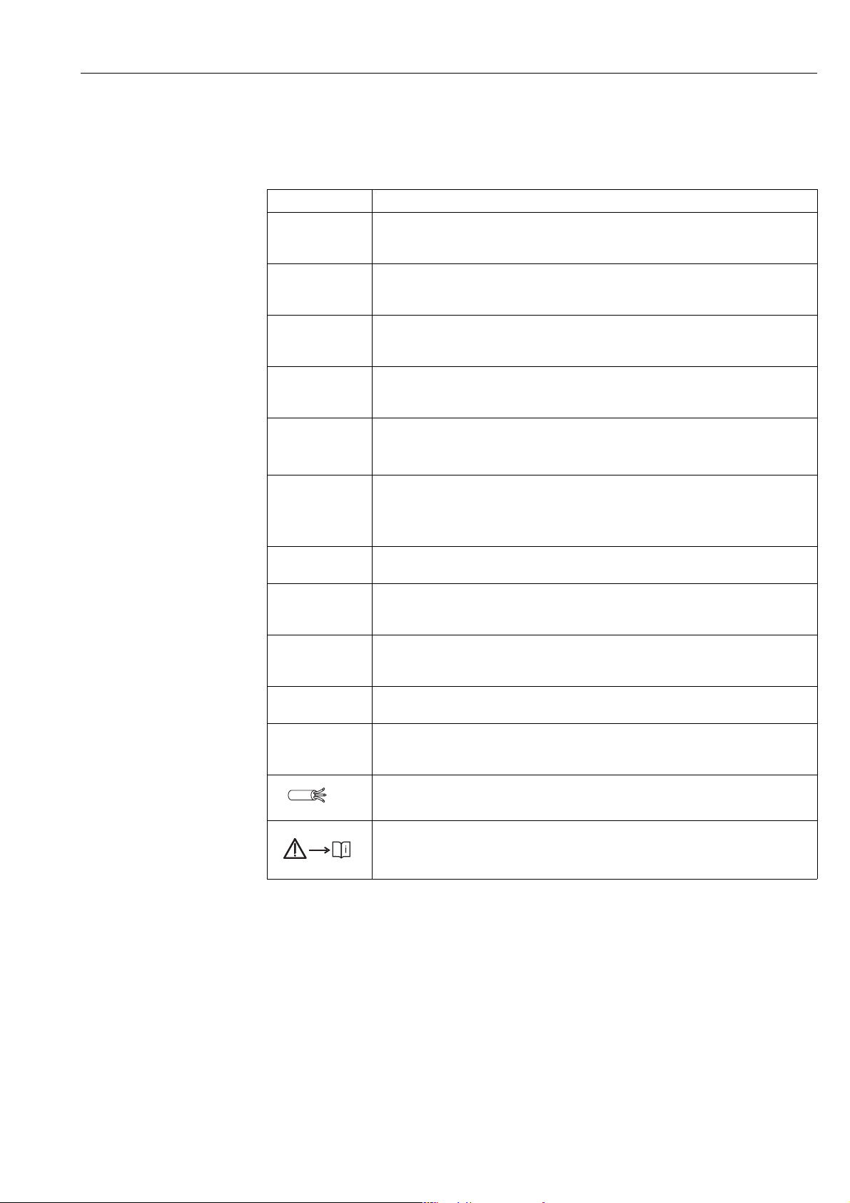
Aluminum and stainless steel housing (T14)
P01-XMX7Xxxx-18-xx-xx-xx-000
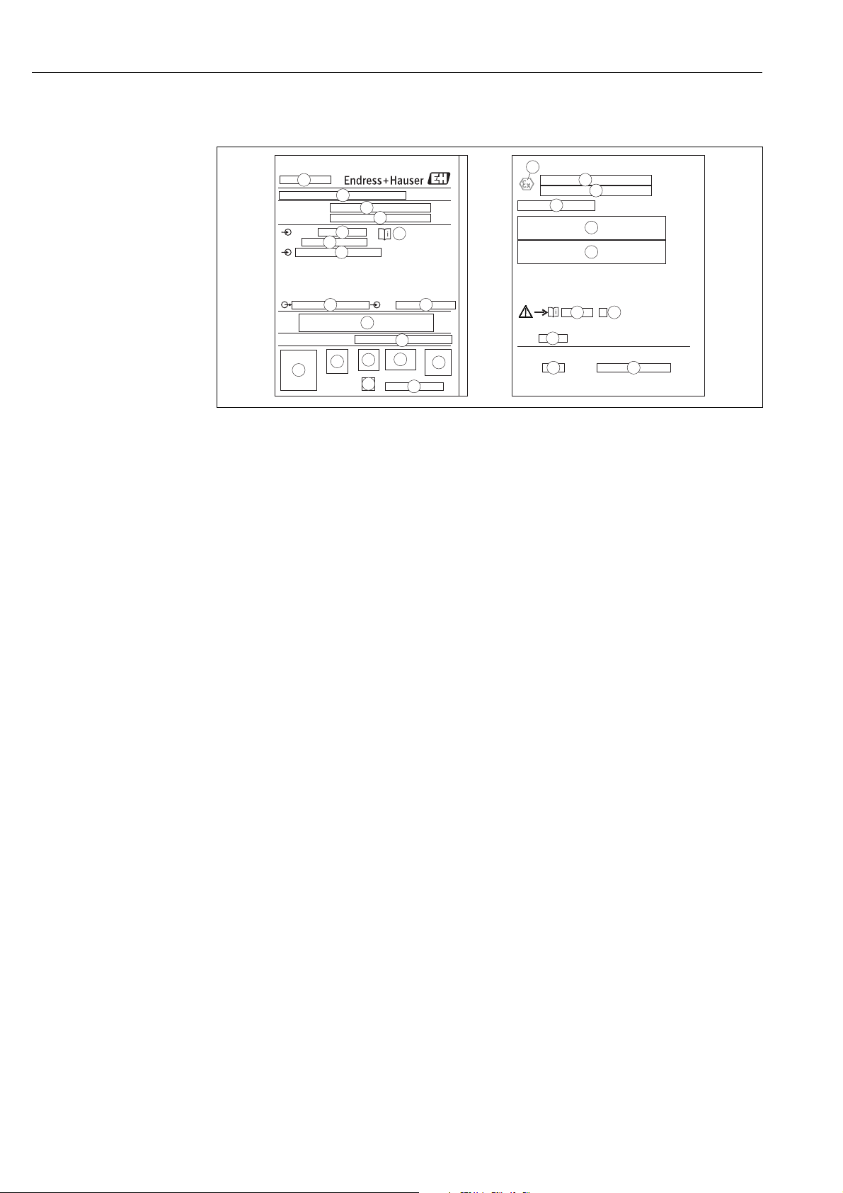
Fig. 1: Nameplate
1 Device name 2 Order code
See the specifications on the order confirmation for the meanings of the individual letters
and digits. 3 Serial number 4 Degree of protection 5 MWP (Maximum working pressure) 6 Symbol: Note: pay particular attention to the data in "Technical Information"! 7 Minimum/maximum span 8 Nominal measuring range 9 Electronic version (output signal) 10 Wetted materials
6 Endress+Hauser
11 Supply voltage 12 GL symbol for GL marine certificate (optional) 13 SIL symbol for devices with SIL3/IEC 61508 Declaration of Conformity (optional) 14 Approval marks and ID numbers 15 Manufacturer's address
Cerabar S PMP71 with 4 to 20 mA HART Identification
Dat.:
3
6
5
1
2
4
Pmax
Tmax
for oxygen service
Bei Sauerstoffeinsatz/
3
1
2
tamb, max.+55°C tamb, min=-25°C
Pmin:
Pmin:
For liquid application:
Pmax:
Pmax:
For gas application:
SW Rev. 02.10.54
NMi Part Certificate TC7975
Checksum: 0xD8CC
1
2
3
4
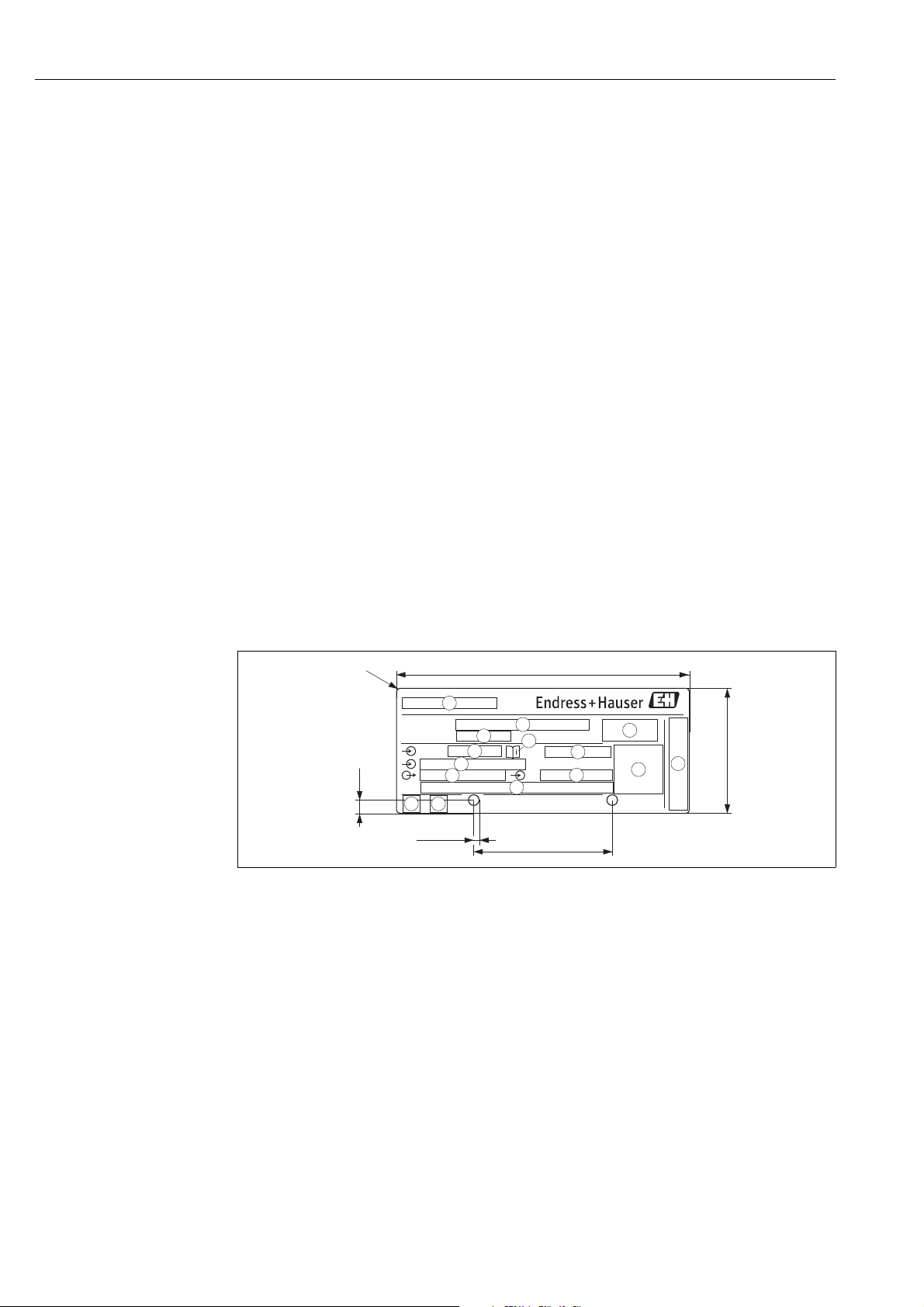
Devices for use in hazardous areas are fitted with an additional nameplate.
P01-xMD7xxxx-18-xx-xx-xx-002
Fig. 2: Additional nameplate for devices suitable for use in hazardous areas
1 EC type-examination certificate number 2 Type of protection e.g. II 1/2 G Ex ia IIC T6 3 Electrical data 4 Safety Instructions number e.g. XA00235P 5 Safety Instructions index e.g. A 6 Date of device manufacture
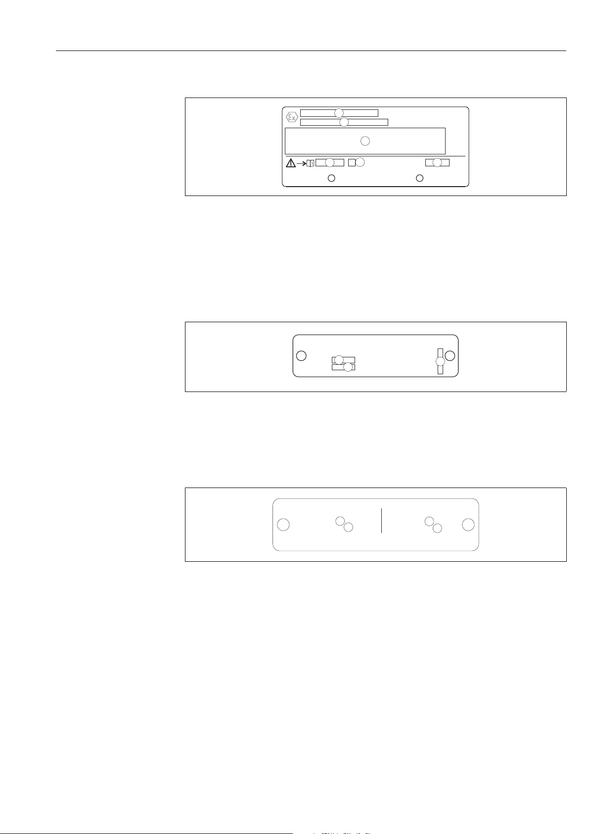
Devices suitable for oxygen applications are fitted with an additional nameplate.
P01-xxxxxxxx-18-xx-xx-xx-000
Fig. 3: Additional nameplate for devices suitable for oxygen applications
1 Maximum pressure for oxygen applications 2 Maximum temperature for oxygen applications 3 Layout identification of the nameplate
Devices suitable for custody transfer applications are fitted with an additional nameplate.
P01-PMP71MID-18-xx-xx-xx-000
Fig. 4: Additional nameplate for devices suitable for custody transfer applications
1 Maximum pressure for liquid applications 2 Minimum pressure for liquid applications 3 Maximum pressure for gas applications 4 Minimum pressure for gas applications
Endress+Hauser 7
Identification Cerabar S PMP71 with 4 to 20 mA HART
15
PmaxTmax
Bei Sauerstoffeinsatz/for oxygen service:
Order Code:
Ser.-No.:
MWP
Span
U=
Mat.
1
3
4
6
7
8
9 10
11
12
13
13
13
14
5
16
17
-
Dat.:
19
21
20
22
23
24
25
26
27
28
2
18
Hygienic stainless steel housing (T17)
P01-XMX7Xxxx-18-xx-xx-xx-001
Fig. 5: Nameplate
1 Device name 2 Manufacturer's address 3 Order code
See the specifications on the order confirmation for the meanings of the individual letters and digits. 4 Serial number 5 MWP (Maximum working pressure) 6 Symbol: Note: pay particular attention to the data in "Technical Information"! 7 Minimum/maximum span 8 Nominal measuring range 9 Electronic version (output signal) 10 Supply voltage 11 Wetted materials 12 Type of protection
Optional: 13 Approval marks and ID numbers 14 3A symbol 15 CSA symbol 16 FM symbol 17 SIL symbol for devices with SIL3/IEC 61508 Declaration of Conformity 18 GL symbol for GL marine certificate 19 EC type-examination certificate 20 Type of protection
21 Approval number for WHG overfill protection 22 Temperature operating range for devices for use in hazardous areas 23 Electrical data for devices for use in hazardous areas 24 Safety Instructions number 25 Safety Instructions index 26 Date of device manufacture 27 Maximum temperature for devices suitable for oxygen applications 28 Maximum pressure for devices suitable for oxygen applications
2.1.2 Identifying the sensor type
See parameter "Sensor Meas.Type" in Operating Instructions BA00413P.
Operating Instructions BA00413P can be found on the supplied CD.
8 Endress+Hauser

Cerabar S PMP71 with 4 to 20 mA HART Identification
2.2 Scope of delivery
The scope of delivery comprises:
• Cerabar S pressure transmitter
• For devices with the "HistoROM/M-DAT" option: CD-ROM with Endress+Hauser operating program and documentation
• Optional accessories
Documentation supplied:
• Operating Instructions BA00412P and BA00413P, Technical Information TI00383P and the Safety Instructions, Safety Manual and brochures can be found on the CD supplied.
• Brief Operating Instructions KA01095P
• Fold-out flyer KA00298P
• Final inspection report
• Also Safety Instructions with ATEX, IECEx and NEPSI devices
• Optional: factory calibration certificate, inspection certificates
2.3 Certificates and approvals
CE mark, Declaration of Conformity
The device is designed to meet state-of-the-art safety requirements, has been tested and left the
factory in a condition in which it is safe to operate. The device complies with the applicable
standards and regulations as listed in the EC Declaration of Conformity and thus complies with the
statutory requirements of the EC Directives. Endress+Hauser confirms the successful testing of the
device by affixing to it the CE mark.
2.4 Registered trademarks
KALREZ®, VITON®, TEFLON
Registered trademarks of E.I. Du Pont de Nemours & Co., Wilmington, USA
TRI-CLAMP
Registered trademark of Ladish & Co., Inc., Kenosha, USA
HART
Registered trademark of HART Communication Foundation, Austin, USA
GORE-TEX
Registered trademark of W.L. Gore & Associates, Inc., USA
®
®
®
®
Endress+Hauser 9

Installation Cerabar S PMP71 with 4 to 20 mA HART
3 Installation
3.1 Incoming acceptance, transport and storage
3.1.1 Incoming acceptance
• Check the packaging and the contents for damage.
• Check the shipment, make sure nothing is missing and that the scope of supply matches your order.
3.1.2 Transporting to the measuring point
Caution!
"
Please comply with the safety instructions and transport conditions for devices weighing over 18 kg
(39.69 lbs).
Transport the device to the measuring point in the original packaging or at the process connection.
3.1.3 Storage
!
The device must be stored in a dry, clean place and protected against damage from impact
(EN 837-2).
Storage temperature range:
See Technical Information TI00383P.
3.2 Installation conditions
3.2.1 Dimensions
For dimensions, please refer to the "Mechanical construction" section in TI00383P.
3.3 Installation instructions
Note!
• Due to the orientation of the Cerabar S, there may be a shift in the zero point, i.e. when the
container is empty or partially full, the measured value does not display zero. You can correct this
zero point shift either directly at the device using the "E" key or by remote operation. See
→ ä 23, "Function of the operating elements – onsite display not connected" or
→ ä 35, "Position adjustment".
• To ensure optimal readability of the onsite display, it is possible to rotate the housing up to 380°. → ä 14, "Rotating the housing".
• Endress+Hauser offers a mounting bracket for installing on pipes or walls. → ä 13, "Wall and pipe-mounting (optional)".
10 Endress+Hauser
Cerabar S PMP71 with 4 to 20 mA HART Installation
1
1
1
FIELDTERMINALS
FIELDTERMINALSFIELDTERMINALS
FIELDTERMINALSFIELDTERMINALS
FIELD
TERMINALS
FIELDTERMINALS
FIELD
TERMINALS
FIELDTERMINALS
FIELD
TERMINALS
FIELDTERMINALS
➀
➁
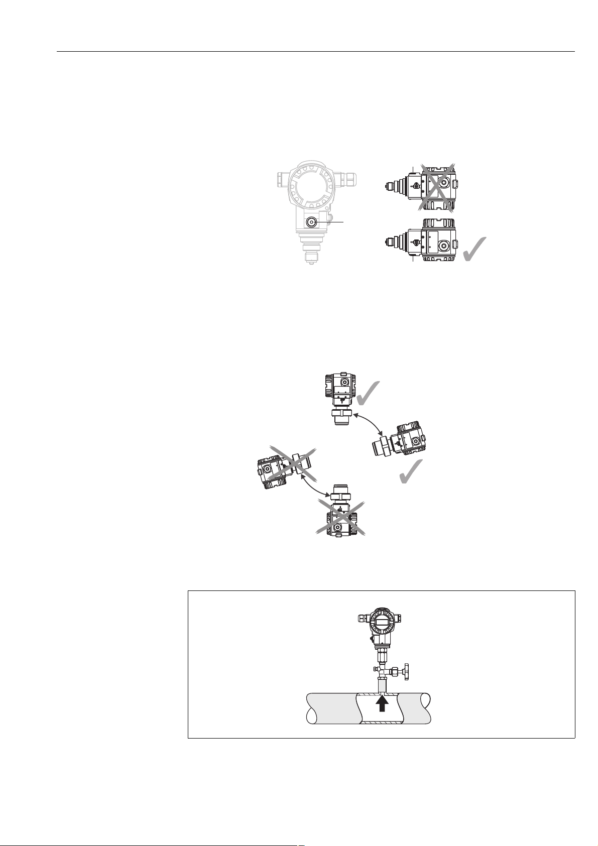
3.3.1 Installation instructions
!
Note!
• If a heated Cerabar S is cooled during the cleaning (e.g. by cold water), a vacuum develops for a
short time, whereby water can penetrate the sensor through the pressure compensation point (1).
If this is the case, mount the sensor with the pressure compensation point (1) pointing
downwards.
®
• Keep the pressure compensation and GORE-TEX
filter (1) free from contamination and water.
• Cerabar S devices are mounted as per the norms for a manometer (DIN EN 837-2). We recommend the use of shutoff devices and siphons. The orientation depends on the measuring application.
• Do not clean or touch process isolating diaphragms with hard or pointed objects.
• To comply with ASME-BPE requirements regarding cleanability (Part SD Cleanability), the device
must be installed as follows:
Pressure measurement in gases
Fig. 6: Measuring arrangement for pressure measurement in gases
1 Cerabar S 2 Shutoff device
Endress+Hauser 11
P01-PMx7xxxx-11-xx-xx-xx-001
Installation Cerabar S PMP71 with 4 to 20 mA HART
➂
➀
➁
➃
➀
➁
➀
➁
Mount Cerabar S with shutoff device above the tapping point so that
any condensate can flow into the process.
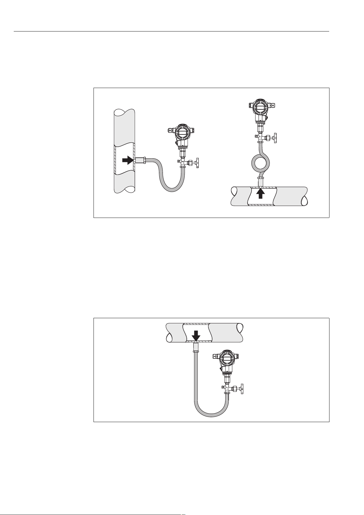
Pressure measurement in steam
Fig. 7: Measuring arrangement for pressure measurement in steam
1 Cerabar S
2 Shutoff device
3 U-shaped siphon
4 Circular siphon
• Mount Cerabar S with siphon above the tapping point.
The siphon reduces the temperature to almost ambient temperature.
• Fill the siphon with fluid before commissioning.
Pressure measurement in liquids
P01-PMx7xxxx-11-xx-xx-xx-002
Fig. 8: Measuring arrangement for pressure measurement in liquids
1 Cerabar S
2 Shutoff device
Mount Cerabar S with shutoff device below or at the same level as the tapping point.
P01-PMx7xxxx-11-xx-xx-xx-003
12 Endress+Hauser
Cerabar S PMP71 with 4 to 20 mA HART Installation
➁➀
52 (2.05)
140 (5.51)
122 (4.8)
70 (2.76)
6 (0.24)
mm (in)
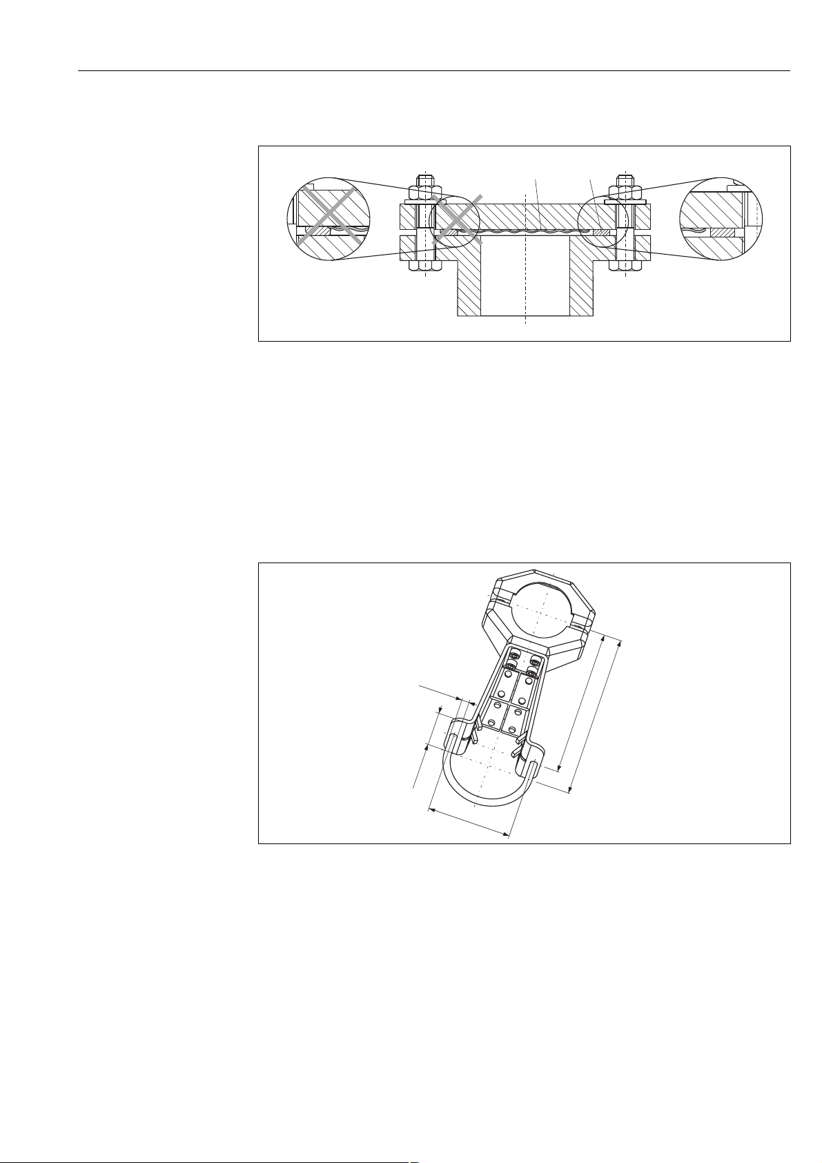
3.3.2 Seal for flange mounting
P01-FMD7xxxx-11-xx-xx-xx-002
Fig. 9: Mounting the versions with flange or diaphragm seal
1 Process isolating diaphragm
2Seal
#
Warning!
The seal is not allowed to press against the process isolating diaphragm as this could affect the
measurement result.
3.3.3 Wall and pipe-mounting (optional)
Endress+Hauser offers a mounting bracket for installing on pipes or walls.
P01-xMx5xxxx-06-xx-xx-xx-001
Please note the following when mounting:
• Devices with capillary tubes: mount capillaries with a bending radius of ≥ 100 mm (3.94 in).
• In the case of pipe mounting, the nuts on the bracket must be tightened uniformly with a torque of at least 5 Nm (3.69 lbf ft).
Endress+Hauser 13
Installation Cerabar S PMP71 with 4 to 20 mA HART
FIELDTERMINALSFIELDTERMINALS
max. 380°
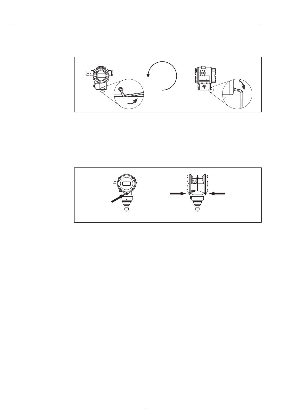
3.3.4 Rotating the housing
The housing can be rotated up to 380° by loosening the setscrew.
P01-PMx7xxxx-17-xx-xx-xx-000
Fig. 10: Aligning the housing
– T14 and T15 housing: Loosen setscrew with a 2 mm (0.08 in) Allen key.
Hygienic T17 housing: Loosen setscrew with a 3 mm (0.12 in) Allen key.
– Rotate housing (max. up to 380°).
– Retighten setscrew with a torque of 1 Nm (0.74 lbf ft).
3.3.5 Closing cover on hygienic stainless steel housing (T17)
P01-PMx7xxxx-17-xx-xx-xx-002
Fig. 11: Closing the cover
The covers for the terminal and electronics compartment are hooked into the casing and closed with a screw. These screws should be hand-tightened (2 Nm, 1.48 lbf ft) to the stop to ensure that the covers sit tightly.
3.4 Post-installation check
After installing the device, carry out the following checks:
• Are all the screws firmly tightened?
• Are the housing covers screwed down tight?
14 Endress+Hauser
Cerabar S PMP71 with 4 to 20 mA HART Wiring
4…20 mA
➅
10.5 V DC
➆
11.5 V DC
4... 20mA
Test
Test
➀
➁
➂
➃
➄
Test
➇
4... 20mA Test
4 Wiring
4.1 Connecting the device
Caution!
"
If the operating voltage is > 35 VDC, do not open the cover when energized in wet locations. Hazardous live voltage at the terminals.
!
Note!
• When using the measuring device in hazardous areas, installation must comply with the corresponding national standards and regulations and the Safety Instructions or Installation or Control Drawings.
• Devices with integrated overvoltage protection must be grounded.
• Protective circuits against reverse polarity, HF influences and overvoltage peaks are integrated.
• The supply voltage must match the supply voltage on the nameplate (→ ä 6, "Nameplates").
• Switch off the supply voltage before connecting the device.
• Remove the housing cover of the terminal compartment.
• Guide the cable through the gland. Preferably use twisted, shielded two-wire cables.
• Connect the device in accordance with the following diagram.
• Screw down the housing cover.
• Switch on the supply voltage.
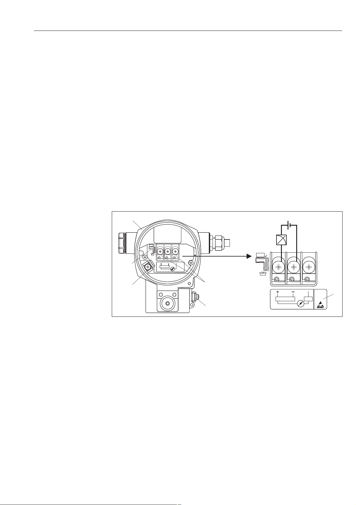
P01-xMx7xxxx-04-xx-xx-xx-001
Fig. 12: Electrical connection 4 to 20 mA HART. Please also note → ä 17, "Supply voltage".
1 Housing
2 Jumper for 4 to 20 mA test signal.
→ ä 17, Section "Taking 4 to 20 mA test signal".
3 Internal earth terminal 4 External earth terminal 5 4 to 20 mA test signal between plus and test terminal 6 Minimum supply voltage = 10.5 V DC, jumper is inserted in accordance with the illustration. 7 Minimum supply voltage = 11.5 V DC, jumper is inserted in "Test" position. 8 Devices with integrated overvoltage protection are labeled OVP (overvoltage protection) here.
Endress+Hauser 15

Wiring Cerabar S PMP71 with 4 to 20 mA HART
Han7D
–
+
+
–
–
+
1
5
4
6
7
8
2
3
21
3
4
+
–
nc
4.1.1 Connecting devices with Harting connector Han7D
P01-xxx7xxxx-04-xx-xx-xx-001
Fig. 13: Left: electrical connection for devices with Harting connector Han7D
Right: view of the connection at the device
4.1.2 Devices with M12 connector
PIN assignment for M12 connector
PIN Meaning
1 signal +
2not used
3 signal –
4ground
A0011175
16 Endress+Hauser
Cerabar S PMP71 with 4 to 20 mA HART Wiring
Test
TestTest
4.2 Connecting the measuring unit
4.2.1 Supply voltage
!
Note!
• When using the measuring device in hazardous areas, installation must comply with the corresponding national standards and regulations and the Safety Instructions or Installation or Control Drawings.
• All explosion protection data are given in separate documentation which is available upon request. The Ex documentation is supplied as standard with all devices approved for use in explosion hazardous areas.
Electronic version Jumper for 4 to 20 mA test signal in
"Test" position (order configuration)
4 to 20 mA HART, version for non-hazardous areas
11.5 to 45 V DC 10.5 to 45 V DC
Jumper for 4 to 20 mA test signal in "Non-Test" position
Taking 4 to 20 mA test signal
A 4 to 20 mA signal may be measured via the positive and test terminal without interrupting the
measurement. The minimum supply voltage of the device can be reduced by simply replugging the
jumper. As a result, operation is also possible with lower voltage sources. To keep the measured
error below 0.1%, the current measuring device should exhibit an internal resistance of < 0.7 Ω.
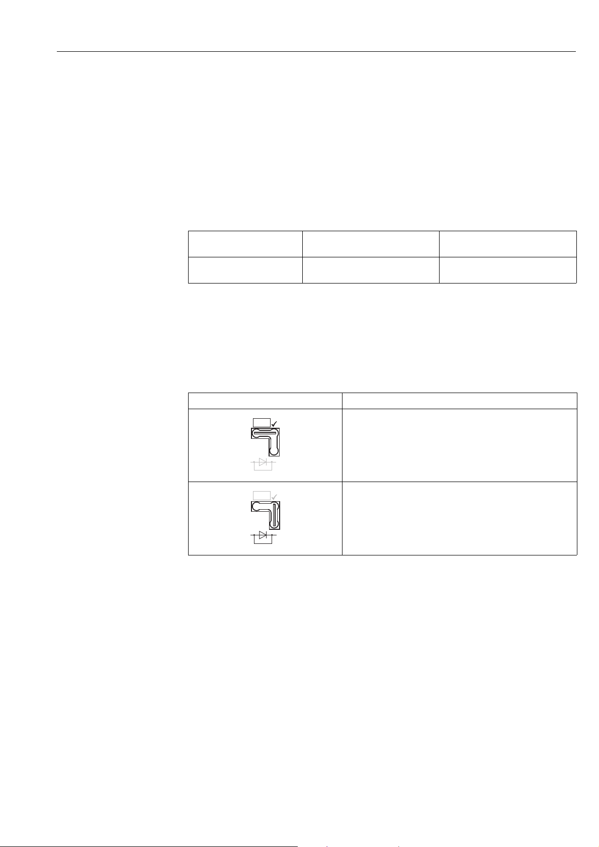
Observe the position of the jumper in accordance with the following table.
Jumper position for test signal Description
– Taking 4 to 20 mA test signal via plus and test terminal:
possible. (Thus, the output current can be measured without
interruption via the diode.)
– Order configuration
– Minimum supply voltage: 11.5 V DC
– Taking 4 to 20 mA test signal via plus and test terminal:
not possible.
– Minimum supply voltage: 10.5 V DC
4.2.2 Cable specification
• Endress+Hauser recommends using twisted, shielded two-wire cables.
• Terminals for wire cross-sections 0.5 to 2.5 mm
• Cable outer diameter: 5 to 9 mm (0.2 to 0.35 in)
2
(20 to 14 AWG)
Endress+Hauser 17
Wiring Cerabar S PMP71 with 4 to 20 mA HART
30
20
10.5
U
[V]
40 45
1282
1500
847
413
[]W
R
L
max
30
20
11.5
U
[V]
40 45
1239
1456
804
369
[]W
R
L
max
TestTest
➀
➁
U – 10.5 V
R
L
max
23 mA
£
U – 11.5 V
R
L
max
23 mA
£
➂
➃
➂
➃
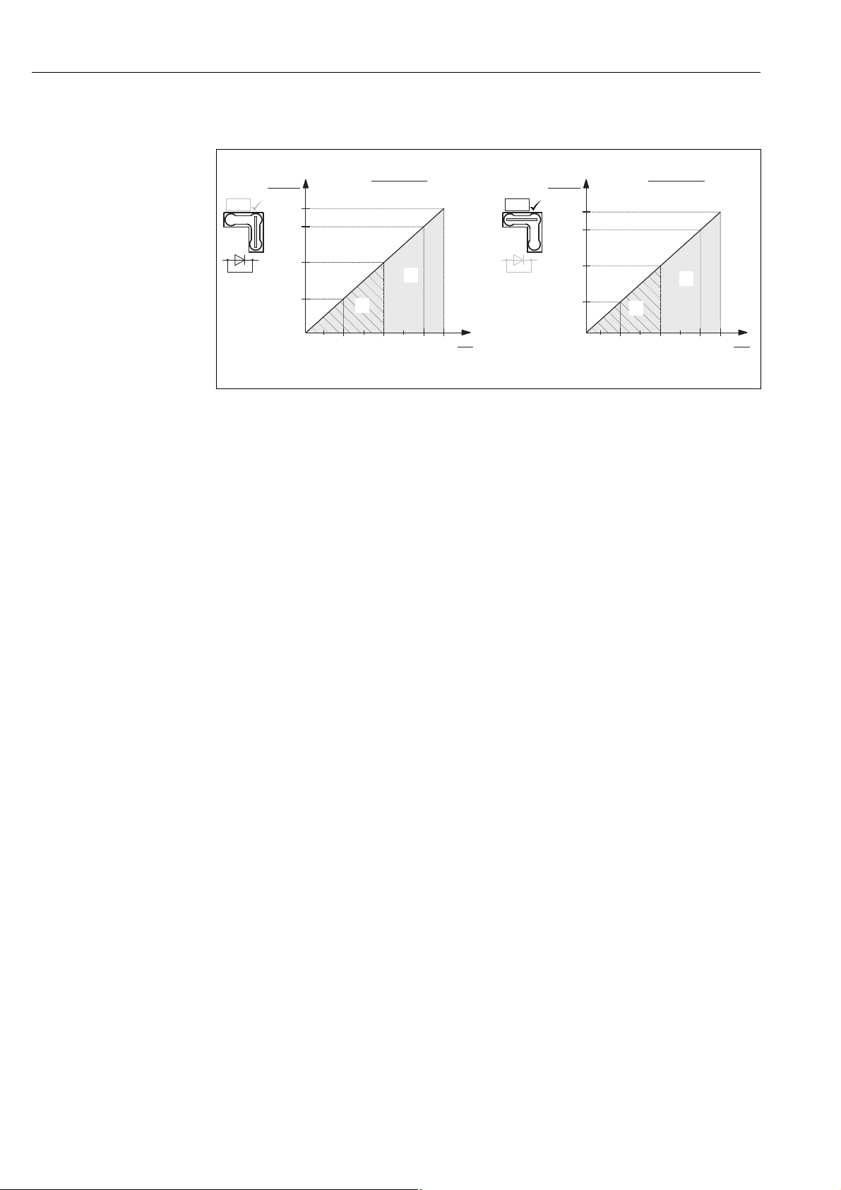
4.2.3 Load
P01-PMP71MID-05-xx-xx-xx-001
Fig. 14: Load diagram, observe the position of the jumper and the explosion protection.
(→ ä 17, Section "Taking 4 to 20 mA test signal".)
1 Jumper for the 4 to 20 mA test signal inserted in "Non-Test" position 2 Jumper for the 4 to 20 mA test signal inserted in "Test" position 3 Supply voltage 10.5 (11.5) to 30 V DC for 1/2 G, 1 GD, 1/2 GD, FM IS , CSA IS, IECEx ia, NEPSI Ex ia 4 Supply voltage 10.5 (11.5) to 45 V DC for devices for non-hazardous areas, 1/2 D, 1/3 D, 2 G Ex d,
3 G Ex nA, FM XP, FM DIP, FM NI, CSA XP, CSA dust ignition-proof, NEPSI Ex d
Maximum load resistance
R
Lmax
U Supply voltage
!
Note!
When operating via a handheld terminal or via a PC with an operating program, a minimum
communication resistance of 250 Ω must be taken into account.
4.2.4 Shielding/potential matching
• You achieve optimum shielding against interference influences if the shielding is connected on
both sides (in the cabinet and at the device). If potential equalization currents are expected in the
plant, only ground the shielding on one side, preferably at the transmitter.
• When using in hazardous areas, you must observe the applicable regulations.
Separate Ex documentation with additional technical data and instructions is included with all
Ex devices as standard.
18 Endress+Hauser
 Loading...