

Page 1
Operating Instructions – Description of device functions
Cerabar S/Deltabar S
Pressure and Differential pressure transmitters
9
BA303P/00/en/04.05
52027503
valid from
Software version 02.00
Hardware version 01.00
Page 2

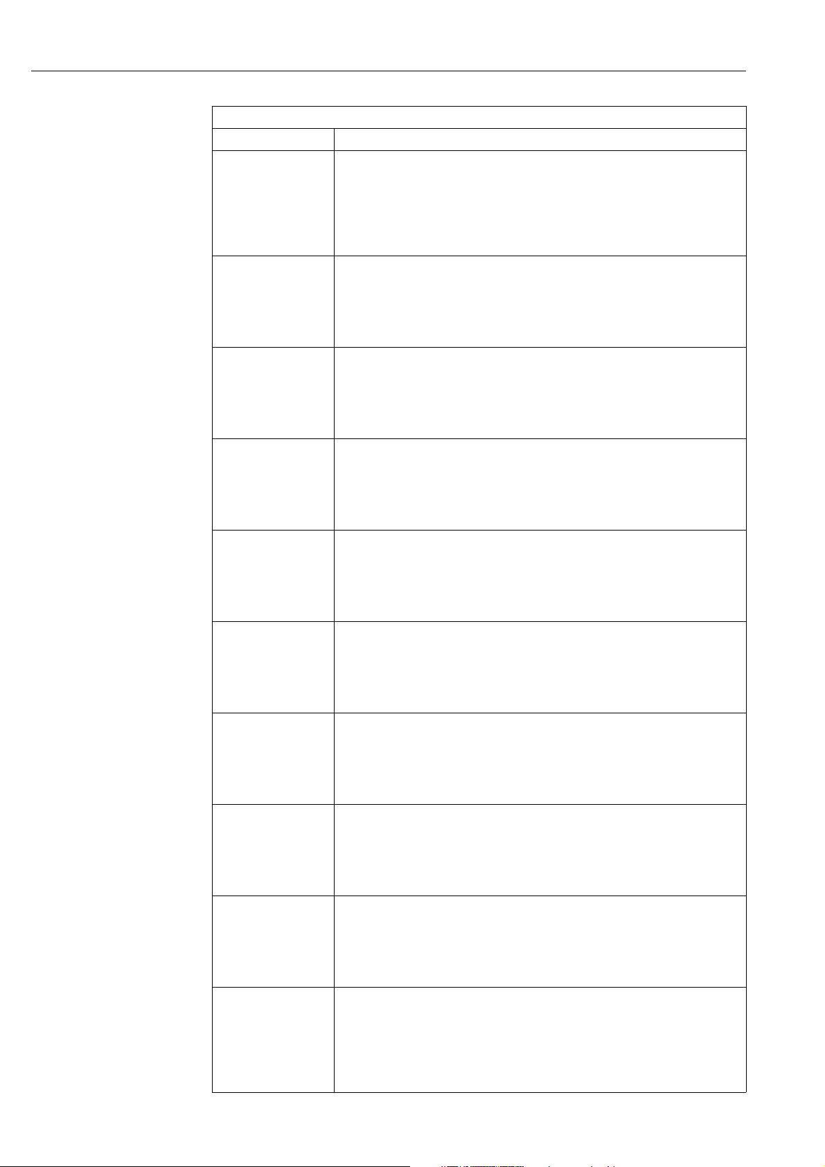
Overview documentation Cerabar S/Deltabar S
Overview documentation
Device Documentation Content Note
Cerabar S FOUNDATION Fieldbus Technical Information TI383P Technical data – The documentation is located on the
ToF Tool CD. The CD is enclosed
with every device ordered with the
"HistoROM/M-DAT" option.
– The documentation is also available
via the Internet. → See:
www.endress.com
Operating Instructions BA302P – Identification
– Installation
– Wiring
– Operation
– Commissioning, Description of
Quick Setup menus
– Maintenance
– Trouble-shooting and spare parts
– Appendix: Illustration of menu
Operating Instructions BA303P – Examples of configuration for
pressure, level and flow
measurement
– Description of parameters
– Trouble-shooting
– Appendix: Illustration of menu
Brief Operating Instructions KA252P – Wiring
– Description of operating elements
– Operation HistoROM
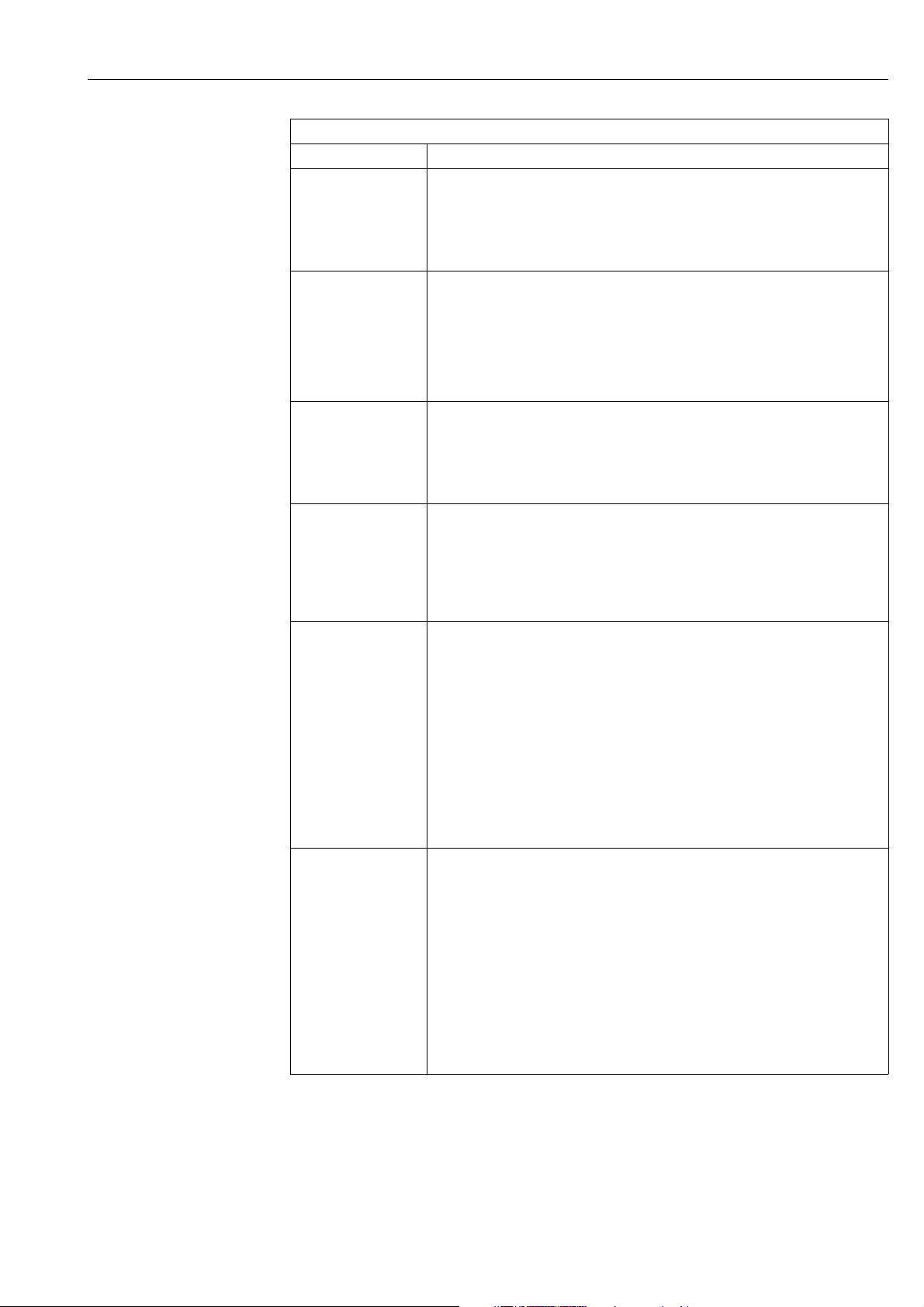
Deltabar S FOUNDATION Fieldbus Technical Information TI382P Technical data – The documentation is located on the
Operating Instructions BA301P – Identification
– Installation
– Wiring
– Operation
– Commissioning, Description of
Quick Setup menus
– Maintenance
– Trouble-shooting and spare parts
– Appendix: Illustration of menu
Operating Instructions BA303P – Examples of configuration for
pressure, level and flow
measurement
– Description of parameters
– ’Trouble-shooting
– Appendix: Illustration of menu
Brief Operating Instructions KA252P – Wiring
– Description of operating elements
– Operation HistoROM
®
/M-DAT
®
/M-DAT
– The documentation is supplied with
the device.
– The documentation is also available
via the Internet. → See:
www.endress.com
– The documentation is also available
via the Internet. → See:
www.endress.com
– The documentation is supplied with
the device. See cover of the terminal
compartment.
ToF Tool CD. The CD is enclosed
with every device ordered with the
"HistoROM/M-DAT" option.
– The documentation is also available
via the Internet. → See:
www.endress.com
– The documentation is supplied with
the device.
– The documentation is also available
via the Internet. → See:
www.endress.com
– The documentation is also available
via the Internet. → See:
www.endress.com
– The documentation is supplied with
the device. See cover of the terminal
compartment.
2 Endress+Hauser
Page 3

Cerabar S/Deltabar S Table of contents
Table of contents
1 Notes on use . . . . . . . . . . . . . . . . . . . . 4
1.1 Finding function group using graphic representation
(ToF Tool) . . . . . . . . . . . . . . . . . . . . . . . . . . . . . . . . 4
1.2 Finding parameter description using parameter names
(index) . . . . . . . . . . . . . . . . . . . . . . . . . . . . . . . . . . 4
2 Graphic representation of function
groups (ToF Tool). . . . . . . . . . . . . . . . . 5
3 Pressure measurement
(FF configuration program). . . . . . . . . . 6
4 Level measurement
(FF configuration program). . . . . . . . . . 7
4. 1 Overview of level measurement . . . . . . . . . . . . . . 7
4. 2 "Linear" level type . . . . . . . . . . . . . . . . . . . . . . . . . 8
4. 3 "Pressure linearized" level type . . . . . . . . . . . . . . 10
4. 4 "Height linearized" level type . . . . . . . . . . . . . . . 14
5 Flow measurement
(FF configuration program). . . . . . . . . 17
10 Description of parameters
(ToF Tool) . . . . . . . . . . . . . . . . . . . . . . 92
11 Trouble-shooting . . . . . . . . . . . . . . . . 151
11.1 Messages . . . . . . . . . . . . . . . . . . . . . . . . . . . . . . . 151
11.2 Response of outputs to errors . . . . . . . . . . . . . . . . 159
11.3 Confirming messages . . . . . . . . . . . . . . . . . . . . . . 160
12 Appendix . . . . . . . . . . . . . . . . . . . . . . 161
12.1 Operating menu (ToF Tool) . . . . . . . . . . . . . . . . . 161
Index . . . . . . . . . . . . . . . . . . . . . . . . . . . . . 167
5. 1 Calibration . . . . . . . . . . . . . . . . . . . . . . . . . . . . . . 17
5. 2 Totalizers . . . . . . . . . . . . . . . . . . . . . . . . . . . . . . . 19
6 Description of parameters
(FF configuration program). . . . . . . . . 21
6.1 Deltabar S and Cerabar S block model . . . . . . . . . . 21
6.2 Resource Block . . . . . . . . . . . . . . . . . . . . . . . . . . . 23
6.3 Transducer Blocks . . . . . . . . . . . . . . . . . . . . . . . . . 31
6. 4 Analog Input Block (function block) . . . . . . . . . . . . 65
7 Pressure measurement (ToF Tool) . . . 74
8 Level measurement (ToF Tool) . . . . . 75
8.1 Overview of level measurement . . . . . . . . . . . . . . 75
8.2 "Linear" level type . . . . . . . . . . . . . . . . . . . . . . . . 76
8.3 "Pressure linearized" level type . . . . . . . . . . . . . . 80
8.4 "Height linearized" level type . . . . . . . . . . . . . . . . 84
9 Flow measurement (ToF Tool) . . . . . . 89
9.1 Calibration . . . . . . . . . . . . . . . . . . . . . . . . . . . . . . 89
9.2 Totalizers . . . . . . . . . . . . . . . . . . . . . . . . . . . . . . . 91
Endress+Hauser 3
Page 4

Notes on use Cerabar S/Deltabar S
1 Notes on use
Sections 3 to 6 describe operation by means of an FF configuration program.
In FOUNDATION Fieldbus, all the device parameters are categorised depending on their functional
properties and tasks and assigned to the Resource Block, the Transducer Blocks and the function
blocks. The parameters of the Resource Block, the Transducer Blocks and the Analog Input Block
are described in Section 6. For a parameter description of other function blocks, such as the PID or
Discrete Output Block, see Operating Instructions BA013S "FOUNDATION Fieldbus Overview" or
the FOUNDATION Fieldbus Specification.
Sections 3 to 5 describe typical configuration examples.
Sections 7 to 10 describe operation by means of the Endress+Hauser ToF Tool operating program.
Section 10 describes all the parameters in the order as they appear in the menu. Sections 7 to 9
describe typical configuration examples.
Sections 1.1 and 1.2 tell you how you can find a certain parameter description more easily.
1.1 Finding function group using graphic representation (ToF Tool)
All the function groups are shown in table form in Section 2. The page reference/link takes you to
the function group in question. In Section 10, all the parameters of a function group are compiled
in a table.
1.2 Finding parameter description using parameter names (index)
The index lists all the parameters in alphabetical order. The page reference/link takes you to the
parameter in question.
4 Endress+Hauser
Page 5

Cerabar S/Deltabar S Graphic representation of function groups (ToF Tool)
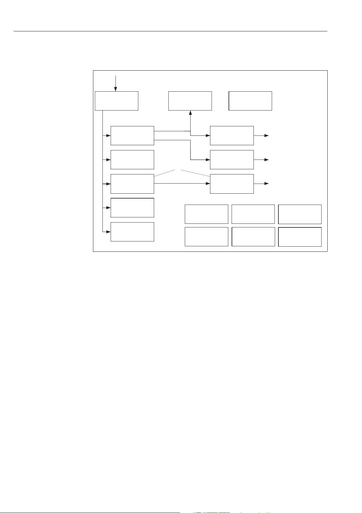
2 Graphic representation of function groups
(ToF Tool)
!
Note!
The "Flow" measuring mode is only available for the Deltabar S differential pressure transmitter. The
groups marked with "*" are only displayed for Deltabar S.
1st selection level 2nd selection level (groups) Function groups Description,
see Page
QUICK SETUP Pressure → → 92
QUICK SETUP Level → → 94
QUICK SETUP Flow * → → 96
OPERATING MENU → SETTINGS → POSITION ADJUSTMENT → 98
→ BASIC SETUP Pressure → 99
→ BASIC SETUP Level → 101
→ BASIC SETUP Flow * → 125
→ EXTENDED SETUP Pressure → 129
→ EXTENDED SETUP Level → 129
→ EEXTENDED SETUP Flow * → 130
→ LINEARISATION → 132
→ TOTALIZER SETUP * → 134
→ DISPLAY → 136
→ TRANSMITTER INFO → INFO → 138
→ TRANSMITTER DATA → 138
→ PROCESS CONNECTION → 139
→ SENSOR DATA → 140
→ PROCESSINFO → PROCESS VALUES pressure → 142
→ PROCESS VALUES level → 143
→ PROCESS VALUES flow * → 144
→ PEAK HOLD INDICATOR → 144
→ OPERATING → 146
→ DIAGNOSTICS → SIMULATION
→ MESSAGES → 149
→ USER LIMITS → 150
→ 148
Endress+Hauser 5
Page 6
Pressure measurement (FF configuration program) Cerabar S/Deltabar S
3 Pressure measurement
(FF configuration program)
!
Note!
• The device is configured for the Pressure measuring mode as standard. The measuring range and
the unit in which the measured value is transmitted, as well as the digital output value of the
Analog Input Block OUT, correspond to the data on the nameplate.
• See also Operating Instructions BA301P Deltabar S, Section 6.7 "Differential pressure
measurement" or Operating Instructions BA302P Cerabar S, Section 6.5 "Pressure
measurement".
• For a description of the parameters mentioned, see
– Page 33, Pressure Transducer Block
– Page 65, Analog Input Block.
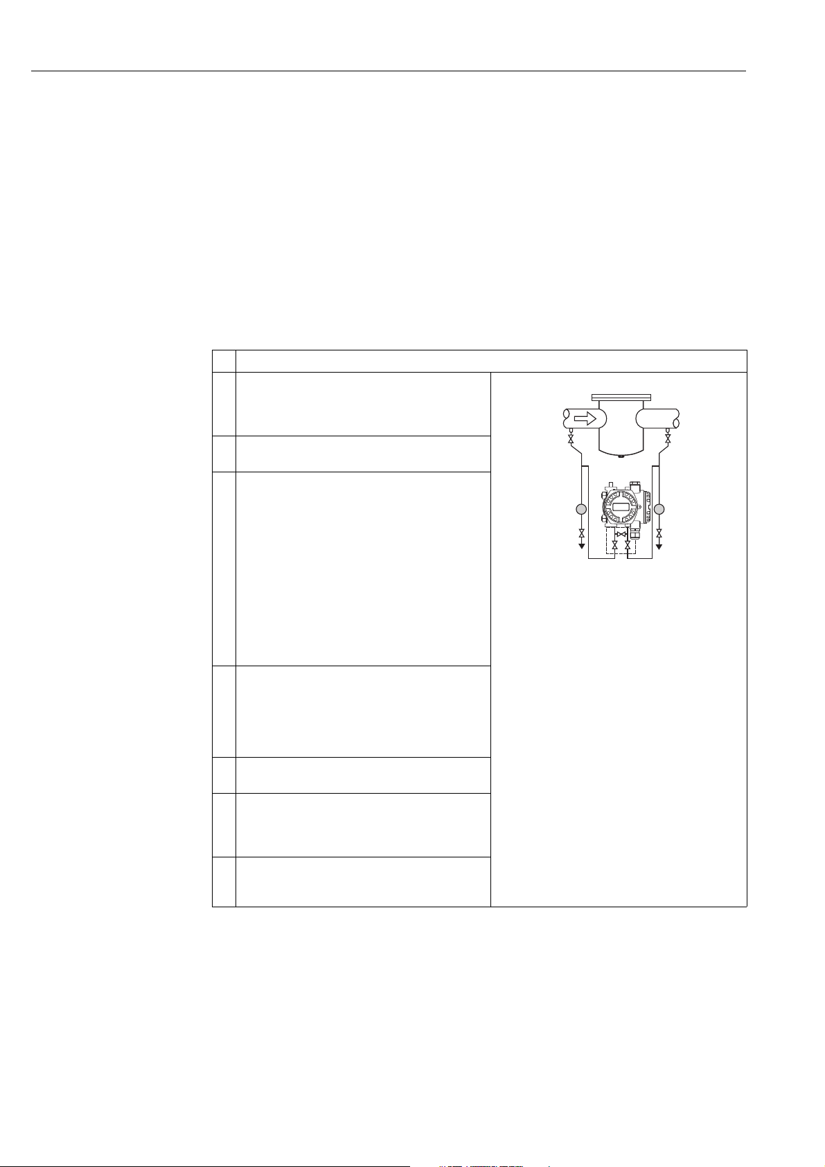
Description
1 Deltabar S: before configuring the device for your
application, the pressure piping must be cleaned and the
device filled with fluid. See Operating Instructions
BA301P, Section 6.7.
2 Open the Pressure Transducer Block and set the block
mode to OOS.
3 Carry out position adjustment if necessary.
You have the following ways of carrying out position
adjustment:
• By means of the "Pos. zero adjust" method, see
Operating Instructions BA301P or BA302P,
Section 6.4.
• By means of the parameters
– PRESSURE_1_ACCEPT_ZERO_INSTALL_
OFFSET/POS. ZERO ADJUST (→ Page 38) or
– PRESSURE_1_ACCEPT_INSTALL_OFFSET/
POS. INPUT VALUE (→ Page 38) or
– PRESSURE_1_INSTALL_OFFSET/CALIB. OFFSET
(→ Page 38).
4 Select the measuring mode if necessary:
• Select the "No linearization" option by means of the
LINEARIZATION parameter.
• Select the "Differential pressure", Gauge pressure" or
"Absolute pressure" option, depending on the sensor,
by means of the PRIMARY_VALUE_TYPE parameter.
5 Set the Pressure Transducer Block to the "Auto" block
mode.
6 If necessary, use the Analog Input Block to configure the
CHANNEL parameter (→ Page 67), L_TYPE parameter
(→ Page 69), XD_SCALE parameter (→ Page 73) and
OUT_SCALE parameter (→ Page 71).
7Result:
The measuring device is ready for pressure
measurement.
+
–
P01-PMD75xxx-19-xx-xx-xx-000
!
Note!
• You can select another pressure unit by means of the CAL_UNIT parameter (→ Page 34). This
parameter also allows you to specify a customer-specific unit.
6 Endress+Hauser
Page 7

Cerabar S/Deltabar S Level measurement (FF configuration program)
4 Level measurement
(FF configuration program)
4. 1 Overview of level measurement
Measuring task Measured variable
selection
The measured variable is in direct
proportion to the measured
pressure.
The measured variable is not in
direct proportion to the measured
pressure as, for example, with
containers with a conical outlet.
A linearisation table must be
entered for the calibration.
– Two measured variables are
required or
– The container shape is given
by value pairs, such as height
and volume.
The 1st measured variable %height or height must be in direct
proportion to the measured
pressure. The 2nd measured
variable volume, mass or % must
not be in direct proportion to the
measured pressure. A
linearisation table must be
entered for the 2nd measured
variable. The 2nd measured
variable is assigned to the 1st
measured variable by means of
this table.
– % (level)
– Level
–Volume
–Mass
– Pressure and %
– Pressure and volume
– Pressure and mass
– Height and volume
– Height and mass
– Height and %
–%-height and volume
–%-height and mass
–%-height and %
LEVEL_TYPE/
LEVEL MODE
Linear Calibration without reference
Pressure linearized – Calibration with reference
Height linearized – Calibration without reference
Description Measured value display
pressure – dry calibration, see
Page 8, Section 4.2.1
pressure: semiautomatic entry
of linearisation table, see
Page 10, Section 4.3.1
– Calibration without reference
pressure: manual entry of
linearisation table, see Page 12,
Section 4.3.2
pressure: dry calibration and
manual entry of linearisation
table, see Page 14, Section
4.4.1
The measured value display and
the PRIMARY_VALUE and
MEASURED_LEVEL_AFTER_
SIMULATION/LEVEL BEFORE
LIN. parameters show the
measured value.
The measured value display and
the PRIMARY_VALUE parameter
display the measured value.
The measured value display and
the PRIMARY_VALUE parameter
display the 2nd measured value
(volume, mass or %).
The MEASURED_LEVEL_
AFTER_SIMULATION/LEVEL
BEFORE LIN parameter displays
the 1st measured value (% height
or height).
Endress+Hauser 7
Page 8
Level measurement (FF configuration program) Cerabar S/Deltabar S
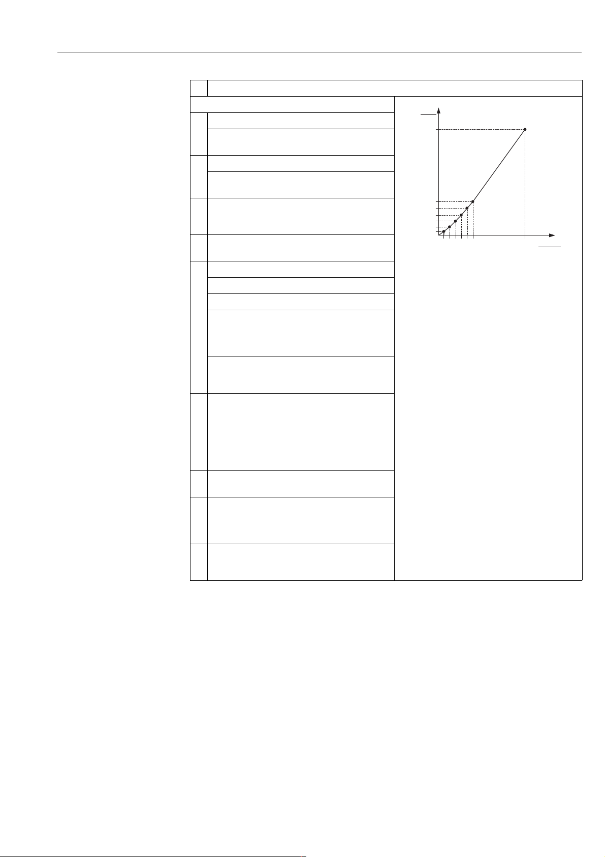
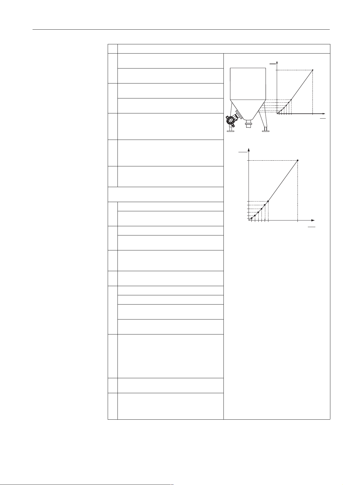
4. 2 "Linear" level type
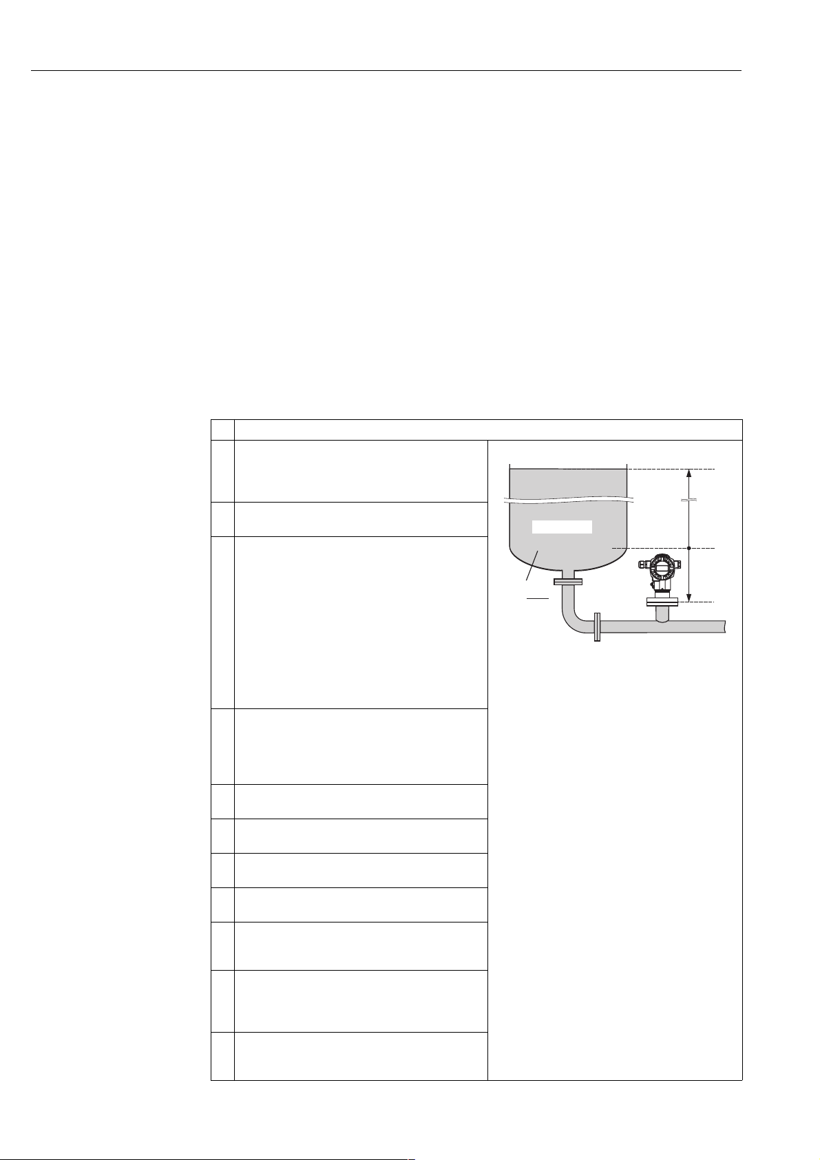
4.2.1 Calibration without reference pressure – dry calibration
!
Example:
In this example, the volume in a tank should be measured in m
and the maximum height is 4 m. The density of the fluid is 1 kg/dm
3
. The maximum volume is 5 m3
3
. The device is mounted below
the level lower range value.
Prerequisite:
• The measured variable is in direct proportion to the pressure.
• This is a theoretical calibration, i.e. the tank volume, tank height and density of the fluid are known.
Note!
• See also Operating Instructions BA301P Deltabar S or Operating Instructions BA302P Cerabar S,
Section 6.6 "Level measurement".
• For a description of the parameters mentioned, see
– Page 33, Pressure Transducer Block
– Page 65, Analog Input Block.
Description
1 Deltabar S: before configuring the device for your
application, the pressure piping must be cleaned and the
device filled with fluid. See Operating Instructions
BA301P, Section 6.6.1.
2 Open the Pressure Transducer Block and set the block
mode to OOS.
3 You have the following ways of carrying out position
adjustment:
• By means of the "Pos. zero adjust" method, see
Operating Instructions BA301P or BA302P, Section
6.4.
• By means of the parameters
– PRESSURE_1_ACCEPT_ZERO_INSTALL_
OFFSET/POS. ZERO ADJUST (→ Page 38) or
– PRESSURE_1_ACCEPT_INSTALL_OFFSET/
POS. INPUT VALUE (→ Page 38) or
– PRESSURE_1_INSTALL_OFFSET/CALIB. OFFSET
(→ Page 38).
4 Select the measuring mode if necessary:
• Select the "No linearization" option by means of the
LINEARIZATION parameter.
• Select the "Volume" option by means of the
PRIMARY_VALUE_TYPE parameter.
5 Select a pressure unit via the CAL_UNIT parameter, here
mbar for example.
6 Select the "Linear" option by means of the
LEVEL_TYPE/LEVEL MODE parameter.
7 Select the "Volume" option by means of the
MEASURAND_LINEAR/LIN. MEASURAND parameter.
8 Select a volume unit via the VOLUME_UNIT/UNIT
VOLUME parameter, here m
9 Select the "Dry" option by means of the
LEVEL_ADJUST_MODE/CALIBRATION MODE
parameter. See also the following note, point 3.
10 Enter the value for density via the
LEVEL_ADJUST_DENSITY/ADJUST DENSITY and
DENSITY_UNIT parameters, here 1 kg/dm
example.
11 Enter the tank volume via the
LEVEL_TANK_VOLUME/TANK VOLUME parameter,
3
here 5 m
for example.
3
for example.
3
for
3
V = 5 m
➁
➀
kg
ρ = 1
3
dm
P01-PMP75xxx-19-xx-xx-xx-003
Fig. 1: Calibration without reference pressure –
dry calibration
1 See Table, Step 10.
2 See Table, Step 11.
3 See Table, Step 12.
4 See Table, Step 13.
➂
4 m
➃
–0.5 m
8 Endress+Hauser
Page 9

Cerabar S/Deltabar S Level measurement (FF configuration program)
Description
12 Enter the tank height via the LEVEL_TANK_HEIGHT/
TANK HEIGHT parameter, here 4 m for example.
13 Enter the level offset via the LEVEL_OFFSET/ZERO
POSITION parameter, here 0.5 m for example.
14 Set the Pressure Transducer Block to the "Auto" block
mode.
15 If necessary, use the Analog Input Block to configure the
CHANNEL parameter (→ Page 67), L_TYPE parameter
(→ Page 69), XD_SCALE parameter (→ Page 73) and
OUT_SCALE parameter (→ Page 71).
16 Result:
The measuring device is ready for level measurement.
!
Note!
1. For this level type, the measured variables %, level, volume and mass are available. → See
Page 40 ff.
2. You can also specify customer-specific units. See parameter descriptions for CAL_UNIT
(→ Page 34), HEIGHT_UNIT (→ Page 41), VOLUME_UNIT (→ Page 42) and MASS_UNIT
(→ Page 43).
3. The "Wet" calibration mode (LEVEL_ADJUST_MODE) is not available by means of the
FF operating programs. A kind of wet calibration can be carried out as follows:
– Select the "No linearization" option by means of the LINEARIZATION parameter.
– Select the "Level", "Volume" or "Mass" option, depending on the measured variable required,
by means of the PRIMARY_VALUE_TYPE parameter.
– Fill the tank up to the lower level point.
– The PRESSURE_1_AFTER_SENSOR/SENSOR PRESSURE parameter displays the pressure
present at the device. Enter the value displayed for the SCALE_IN parameter, EU_0
element.
– Enter the associated level value for the SCALE_OUT parameter, EU_0 element.
– Using the SCALE_OUT parameter, "Units Index" element, select a unit to suit the measured
variable.
– Fill the tank up to the upper level point.
– The PRESSURE_1_AFTER_SENSOR/SENSOR PRESSURE parameter displays the pressure
present at the device. Enter the value displayed for the SCALE_IN parameter, EU_100
element.
– Enter the associated level value for the SCALE_OUT parameter, EU_100 element.
Endress+Hauser 9
Page 10
Level measurement (FF configuration program) Cerabar S/Deltabar S
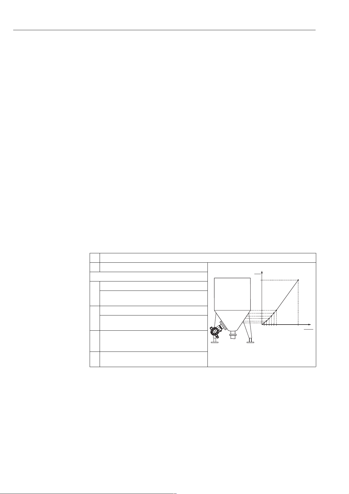
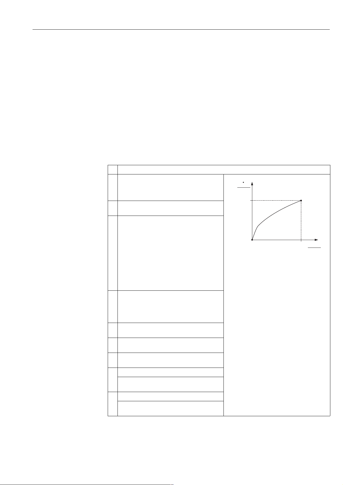
4. 3 "Pressure linearized" level type
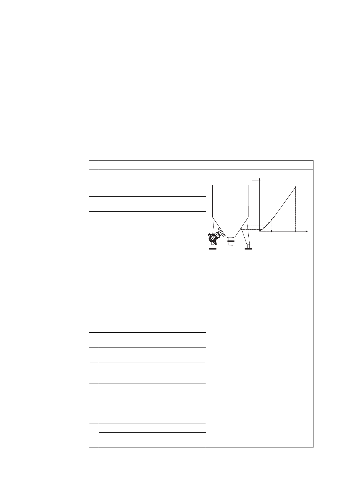
4.3.1 Semiautomatic entry of the linearisation table
!
Example:
In this example, the volume in a tank with a conical outlet should be measured in m
3
.
Prerequisite:
• The tank can be filled. The linearisation characteristic must rise continuously.
Note!
• See also Operating Instructions BA301P Deltabar S or Operating Instructions BA302P Cerabar S,
Section 6.6 "Level measurement".
• For a description of the parameters mentioned, see
– Page 33, Pressure Transducer Block.
– Page 65, Analog Input Block.
Description
1 Deltabar S: before configuring the device for your
application, the pressure piping must be cleaned and the
device filled with fluid. See Operating Instructions
BA301P, Section 6.6.1.
2 Open the Pressure Transducer Block and set the block
mode to OOS.
3 You have the following ways of carrying out position
adjustment:
• By means of the "Pos. zero adjust" method, see
Operating Instructions BA301P or BA302P,
Section 6.4.
• By means of the parameters
– PRESSURE_1_ACCEPT_ZERO_INSTALL_
OFFSET/POS. ZERO ADJUST (→ Page 38) or
– PRESSURE_1_ACCEPT_INSTALL_OFFSET/
POS. INPUT VALUE (→ Page 38) or
– PRESSURE_1_INSTALL_OFFSET/CALIB. OFFSET
(→ Page 38).
Carry out basic setup:
4 Select the measuring mode if necessary:
• Select the "Level linearized" option by means of the
LINEARIZATION parameter.
• Select the "Volume" option by means of the
PRIMARY_VALUE_TYPE parameter. See also the
following note, point 3.
5 Select a pressure unit via the CAL_UNIT parameter, here
mbar for example.
6 Select the "Pressure linearized" option by means of the
LEVEL_TYPE/LEVEL MODE parameter.
7 Select the "Pressure and volume" option by means of the
MEASURAND_LINEAR/Lind. MEASURAND
parameter.
8 Select a volume unit via the VOLUME_UNIT/UNIT
VOLUME parameter, here m
9Select SCALE_IN parameter, EU_0 element.
Enter the minimum hydrostatic pressure to be expected,
here 0 mbar for example.
10 Select SCALE_IN parameter, EU_100
Enter the maximum hydrostatic pressure to be expected,
here 350 mbar for example.
3
for example.
element.
V
3
[m ]
3.5
0
0 350
P01-PMP75xxx-19-xx-xx-xx-002
p
[mbar]
10 Endress+Hauser
Page 11
Cerabar S/Deltabar S Level measurement (FF configuration program)
Description
Carry out linearisation:
11 Select SCALE_OUT parameter, EU_0 element.
Specify the minimum tank contents to be expected, here
3
0 m
for example.
12 Select SCALE_OUT parameter, EU_100 element.
Specify the maximum tank contents to be expected, here
3
3.5 m
for example. See also the following note, point 4.
13 Select the "Semiautomatic" option by means of the
LINEARIZATION_TABLE_MODE/LIN. EDIT MODE
parameter.
14 Select the "Edit table" option by means of the
TAB_OBCODE/TABLE SELECTION parameter.
15 Enter linearisation table (min. 2 points, max. 32 points).
Fill the tank to the height of the 1st point.
TAB_ENTRY: enter the value of the corresponding point.
The PRESSURE_1_AFTER_DAMPING/PRESSURE
parameter displays the measured hydrostatic pressure.
This hydrostatic pressure displayed is saved by
confirming the Y-value. See the following line.
TAB_XY_VALUE, 2nd element (Y-value): enter the
volume value, here 0 m
value.
16 You can enter further points for the linearisation table as
explained in Step 15. The previous point first has to be
saved in the linearisation table before the next point can
be entered. In other words, a complete linearisation table
cannot be saved to the device. Once all the points have
been entered, the table must be activated by means of
the TAB_OBCODE/TABLE SELECTION parameter.
17 Set the Pressure Transducer Block to the "Auto" block
mode.
18 If necessary, use the Analog Input Block to configure the
CHANNEL parameter (→ Page 67), L_TYPE parameter
(→ Page 69), XD_SCALE parameter (→ Page 73) and
OUT_SCALE parameter (→ Page 71).
19 Result:
The linearisation table is entered and the measuring
device is ready for level measurement.
3
for example, and confirm the
V
3
[m ]
3.5
➃
➄
0
➂
0 350
➀
Fig. 2: Semiautomatic entry of the linearisation
table
1 See Table, Step 9.
2 See Table, Step 10.
3 See Table, Step 11.
4 See Table, Step 12.
5 See Table, Steps 13 to 16.
p
[mbar]
➁
P01-xxxxxxxx-05-xx-xx-xx-015
!
Note!
1. For this level type, the measured variables %, volume and mass are available. → See Page 40 ff.
2. You can also specify customer-specific units. See parameter descriptions for CAL_UNIT
(→ Page 34), HEIGHT_UNIT (→ Page 41), VOLUME_UNIT (→ Page 42) and MASS_UNIT
(→ Page 43).
Endress+Hauser 11
Page 12
Level measurement (FF configuration program) Cerabar S/Deltabar S
3. Once you have selected the "Pressure linearized" level type (LEVEL_TYPE), the warning
message "W710 Set span too small. Not allowed." can appear. At this stage the linearisation
table already consists of two points as standard. It could be the case that the 2nd value, and
thus the highest X-value of the linearisation table, is smaller than the minimum span permitted
(→ CAL_MIN_SPAN, Page 34). The message goes out as soon as the highest X-value is larger
than the minimum span and the table entered is active.
4. Once you have entered the maximum tank contents to be expected for SCALE_OUT, EU_100
element, the alarm "A719 Y-Val of lin. table out of edit limits" can appear. At this stage the
linearisation table already consists of two points as standard. It could be the case that the 2nd
value, and thus the highest Y-value of the linearisation table, is larger than the value entered
for SCALE_OUT, EU_100 element. The message goes out as soon as no Y-value is larger than
the value for SCALE_OUT, EU_100 element and the table entered is active.
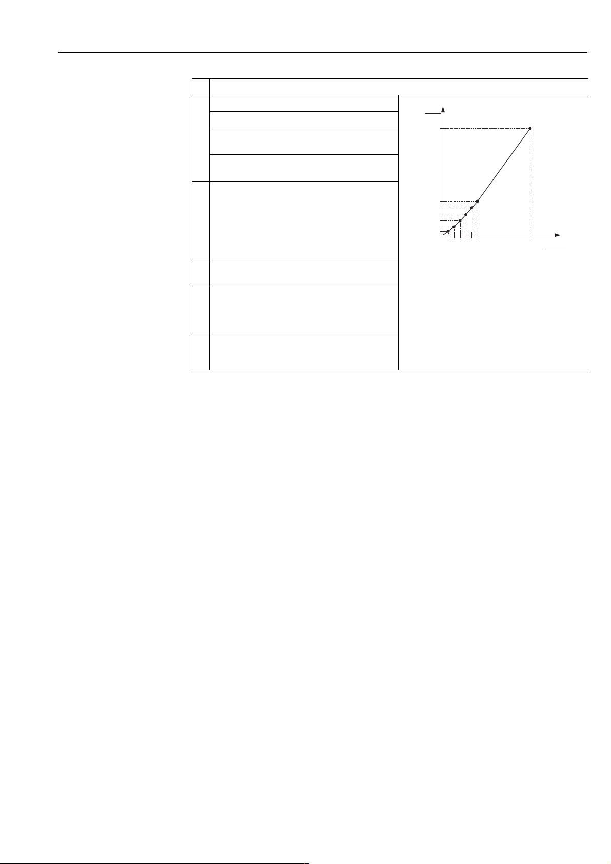
4.3.2 Manual entry of the linearisation table
!
Example:
In this example, the volume in a tank with a conical outlet should be measured in m
3
.
Prerequisite:
• This is a theoretical calibration, i.e. the points for the linearisation table are known.
Note!
• See also Operating Instructions BA301P Deltabar S or Operating Instructions BA302P Cerabar S,
Section 6.6 "Level measurement".
• For a description of the parameters mentioned, see
– Page 33, Pressure Transducer Block.
– Page 65, Analog Input Block.
Description
1 Perform calibration as per Section 4.3.1, Steps 1 to 10.
Carry out linearisation:
2 Select SCALE_OUT parameter, EU_0 element.
Specify the minimum tank contents to be expected, here
3
0 m
for example.
3Select SCALE_OUT parameter, EU_100 element.
Specify the maximum tank contents to be expected, here
3
3.5 m
for example. See also the following note, point 3.
4 Select the "Manual" option by means of the
LINEARIZATION_TABLE_MODE/LIN. EDIT MODE
parameter.
5 Select the "Edit table" option by means of the
TAB_OBCODE/TABLE SELECTION parameter.
V
3
[m ]
3.5
0
0 350
P01-PMP75xxx-19-xx-xx-xx-002
p
[mbar]
12 Endress+Hauser
Page 13
Cerabar S/Deltabar S Level measurement (FF configuration program)
Description
6 Enter linearisation table (min. 2 points, max. 32 points).
TAB_ENTRY: enter the value of the corresponding point.
TAB_XY_VALUE, 1st element (X-value): enter the
pressure value.
TAB_XY_VALUE, 2nd element (Y-value): enter the
volume value, here 0 m
7 You can enter further points for the linearisation table as
explained in Step 6. The previous point first has to be
saved in the linearisation table before the next point can
be entered. In other words, a complete linearisation table
cannot be saved to the device. Once all the points have
been entered, the table must be activated by means of
the TAB_OBCODE/TABLE SELECTION parameter.
8 Set the Pressure Transducer Block to the "Auto" block
mode.
9 If necessary, use the Analog Input Block to configure the
CHANNEL parameter (→ Page 67), L_TYPE parameter
(→ Page 69), XD_SCALE parameter (→ Page 73) and
OUT_SCALE parameter (→ Page 71).
10 Result:
The linearisation table is entered and the measuring
device is ready for level measurement.
3
for example, and confirm.
V
3
[m ]
3.5
➃
➄
0
➂
0 350
➀
Fig. 3: Manual entry of the linearisation table
1 See Section 4.3.1, Table, Step 9.
2 See Section 4.3.1, Table, Step 10.
3 See this Table, Step 2.
4 See this Table, Step 3.
5 See this Table, Steps 4 to 7.
p
[mbar]
➁
P01-xxxxxxxx-05-xx-xx-xx-015
!
Note!
1. For this level type, the measured variables %, volume and mass are available. → See Page 40 ff.
2. You can also specify customer-specific units. See parameter descriptions for CAL_UNIT
(→ Page 34), HEIGHT_UNIT (→ Page 41), VOLUME_UNIT (→ Page 42) and MASS_UNIT
(→ Page 43).
3. Once you have entered the maximum tank contents to be expect ed f or S CAL E_OUT, EU_100
element, the alarm "A719 Y-Val of lin. table out of edit limits" can appear. At this stage the
linearisation table already consists of two points as standard. It could be the case that the 2nd
value, and thus the highest Y-value of the linearisation table, is larger than the value entered
for SCALE_OUT, EU_100 element. The message goes out as soon as no Y-value is larger than
the value for SCALE_OUT, EU_100 element and the table entered is active.
Endress+Hauser 13
Page 14
Level measurement (FF configuration program) Cerabar S/Deltabar S
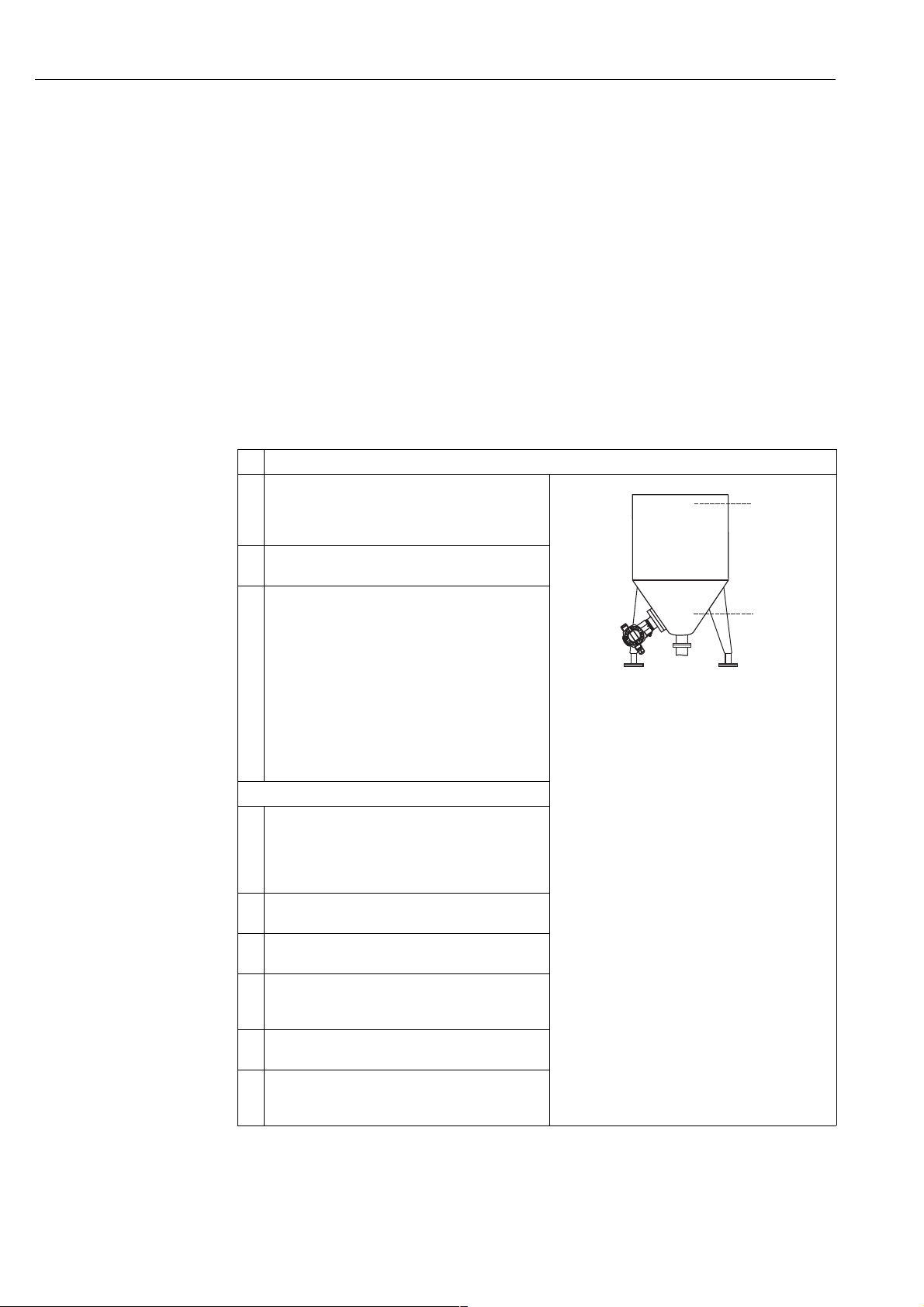
4. 4 "Height linearized" level type
4.4.1 Dry calibration and manual entry of the linearisation table
Example:
In this example, the height and the volume should be measured at the same time.
Prerequisite:
• This is a theoretical calibration, i.e. the points for the linearisation table are known.
!
Note!
• See also Operating Instructions BA301P Deltabar S or Operating Instructions BA302P Cerabar S,
Section 6.6 "Level measurement".
• For a description of the parameters mentioned, see
– Page 33, Pressure Transducer Block.
– Page 65, Analog Input Block.
Description
1 Deltabar S: before configuring the device for your
application, the pressure piping must be cleaned and the
device filled with fluid. See Operating Instructions
BA301P, Section 6.6.1
2 Open the Pressure Transducer Block and set the block
mode to OOS.
3 You have the following ways of carrying out position
adjustment:
• By means of the "Pos. zero adjust" method, see
Operating Instructions BA301P or BA302P,
Section 6.4.
• By means of the parameters
– PRESSURE_1_ACCEPT_ZERO_INSTALL_
OFFSET/POS. ZERO ADJUST (→ Page 38) or
– PRESSURE_1_ACCEPT_INSTALL_OFFSET/
POS. INPUT VALUE (→ Page 38) or
– PRESSURE_1_INSTALL_OFFSET/CALIB. OFFSET
(→ Page 38).
Perform calibration for the 1st measured variable:
4 Select the measuring mode if necessary:
• Select the "Level combined" option by means of the
LINEARIZATION parameter.
• Select the "Volume" option by means of the
PRIMARY_VALUE_TYPE parameter.
5 Select a pressure unit via the CAL_UNIT parameter, here
mbar for example.
6 Select the "Height linearised" option by means of the
LEVEL_TYPE/LEVEL MODE parameter.
7 Select the "Height + volume" option by means of the
MEASURAND_COMBINED/COM. MEASURAND
parameter.
8 Select the unit for the 1st measured value via the
HEIGHT UNIT parameter, here m for example.
9 Select the unit for the 2nd measured variable via the
VOLUME_UNIT/UNIT VOLUME parameter, here m
for example.
3
Fig. 4: Calibrating the 1st measured variable
1 See Table, Step 10.
2 See Table, Step 11.
➁
➀
P01-PMP75xxx-19-xx-xx-xx-006
14 Endress+Hauser
Page 15
Cerabar S/Deltabar S Level measurement (FF configuration program)
Description
10 Select the LINEAR_LEVEL_MIN/LEVEL MIN.
parameter.
Enter the minimum level to be expected, here 0 m for
example.
11 Select the LINEAR_LEVEL_MAX/LEVEL MAX.
parameter.
Enter the maximum height to be expected, here 3 m for
example. See also the following note, point 3.
12 Select the "Dry" option by means of the
LEVEL_ADJUST_MODE/ CALIBRATION MODE
parameter (calibration mode for the 1st measured
variable). See also the following note, point 4.
13 Enter the value for density via the
LEVEL_ADJUST_DENSITY/ADJUST DENSITY and
DENSITY_UNIT parameters, here 1 kg/dm
3
for
example.
14 Result:
The calibration for the 1st measured variable is carried
out.
Perform linearisation (calibration for the 2nd
measured variable)
15 Select SCALE_OUT parameter, EU_0 element.
Specify the minimum tank contents to be expected, here
3
0 m
for example.
16 Select SCALE_OUT parameter, EU_100 element.
Specify the maximum tank contents to be expected, here
3
5 m
for example.
17 Select the "Manual" option by means of the
LINEARIZATION_TABLE_MODE/LIN. EDIT MODE
parameter.
18 Select the "Edit table" option by means of the
TAB_OBCODE/TABLE SELECTION parameter.
19 Enter linearisation table (min. 2 points, max. 32 points).
TAB_ENTRY: enter the value of the corresponding point.
TAB_XY_VALUE, 1st element (X-value): enter the level,
here 0 m for example.
TAB_XY_VALUE, 2nd element (Y-value): enter the
volume value, here 0 m
3
.
20 You can enter further points for the linearisation table as
explained in Step 19. The previous point first has to be
saved in the linearisation table before the next point can
be entered. In other words, a complete linearisation table
cannot be saved to the device. Once all the points have
been entered, the table must be activated by means of
the TAB_OBCODE/TABLE SELECTION parameter.
21 Set the Pressure Transducer Block to the "Auto" block
mode.
22 If necessary, use the Analog Input Block to configure the
CHANNEL parameter (→ Page 67), L_TYPE parameter
(→ Page 69), XD_SCALE parameter (→ Page 73) and
OUT_SCALE parameter (→ Page 71).
V
3
[m ]
5
➃
0
➂
03
Fig. 5: Calibrating the 2nd measured variable
3 See Table, Step 15
4 See Table, Step 16.
5 See Table, Steps 17 to 20.
V
3
[m ]
5
0
03
P01-PMP75xxx-19-xx-xx-xx-005
[m]
h
➄
h
[m]
P01-xxxxxxxx-05-xx-xx-xx-022
Endress+Hauser 15
Page 16

Level measurement (FF configuration program) Cerabar S/Deltabar S
Description
23 Result:
– The linearisation table has been entered.
– The measured value display and the
PRIMARY_VALUE parameter display the 2nd
measured value (here the volume).
– The MEASURED_LEVEL_AFTER_SIMULATION/
LEVEL BEFORE LIN parameter displays the 1st
measured value (here the height). See also the
following note, point 5.
!
Note!
1. For this level type, the measured variables "height + %", "height + volume", "height + mass",
"%-height + %", "%-height + volume" and "%-height + mass" are available.
→ See Page 41 ff.
2. You can also specify customer-specific units. See parameter descriptions for CAL_UNIT
(→ Page 34), HEIGHT_UNIT (→ Page 41), VOLUME_UNIT (→ Page 42) and MASS_UNIT
(→ Page 43).
3. Once you have entered the maximum height to be expected for LINEAR_LEVEL_MAX/
LEVEL MAX., the alarm "A707 X-Val of lin. table out of edit limits" can appear. At this stage
the linearisation table already consists of two points as standard. It could be the case that the
2nd value, and thus the highest X-value of the linearisation table, is greater than the maximum
level entered. The message goes out as soon as the highest X-value is larger than the maximum
level and the table entered is active.
4. The "Wet" calibration mode is not available by means of the FF operating programs.
5. You can use the DISPLAY_MAINLINE_CONTENT/ MENU DESCRIPTOR parameter
(→ Page 60) to specify which measured value should be displayed on the on-site display.
16 Endress+Hauser
Page 17
Cerabar S/Deltabar S Flow measurement (FF configuration program)
5Flow measurement
(FF configuration program)
5. 1 Calibration
!
Example:
In this example, a volume flow should be measured in m
3
/h.
Note!
• The "Flow measurement" measuring mode is only available for the Deltabar S differential pressure
transmitter.
• See also Operating Instructions BA301P Deltabar S, Section 6.5 "Flow measurement".
• For a description of the parameters mentioned, see
– Page 33, Pressure Transducer Block.
– Page 65, Analog Input Block.
Description
1 Before configuring the device for your application, the
pressure piping must be cleaned and the device filled
with fluid. See Operating Instructions BA301P, Section
6.5.1.
2 Open the Pressure Transducer Block and set the block
mode to OOS.
3 Carry out position adjustment if necessary.
You have the following ways of carrying out position
adjustment:
• By means of the "Pos. zero adjust" method, see
Operating Instructions BA301P, Section 6.4.
• By means of the parameters
– PRESSURE_1_ACCEPT_ZERO_INSTALL_
OFFSET/POS. ZERO ADJUST (→ Page 38) or
– PRESSURE_1_ACCEPT_INSTALL_OFFSET/
POS. INPUT VALUE (→ Page 38) or
– PRESSURE_1_INSTALL_OFFSET/CALIB. OFFSET
(→ Page 38).
4 Select the measuring mode if necessary:
• Select the "Flow Square root" option by means of the
LINEARIZATION parameter.
• Select the "Flow" option by means of the
PRIMARY_VALUE_TYPE parameter.
5 Select a pressure unit via the CAL_UNIT parameter, here
mbar for example.
6 Select the "Volume p. cond." option by means of the
FLOW_TYPE/FLOW-MEAS. TYPE parameter.
7 Select a flow unit via the FLOW_UNIT/UNIT FLOW
parameter, here m
8 Select SCALE_OUT parameter, EU_100 element.
Enter the maximum flow value of the primary device,
here 6000 m
9 Select SCALE_IN parameter, EU_100 element.
Enter the maximum pressure, here 400 mbar for
example. See also layout sheet of primary device.
3
/h for example.
3
/h. See also layout sheet of primary device.
V
3
[m /h]
6000
➀
0
0 400
Fig. 6: Flow measurement calibration
1 See Table, Step 8.
2 See Table, Step 9.
p
[mbar]
➁
P01-xMD7xxx-05-xx-xx-xx-010
Endress+Hauser 17
Page 18

Flow measurement (FF configuration program) Cerabar S/Deltabar S
Description
10 Set the Pressure Transducer Block to the "Auto" block
mode.
11 If necessary, use the Analog Input Block to configure the
CHANNEL parameter (→ Page 67), L_TYPE parameter
(→ Page 69), XD_SCALE parameter (→ Page 73) and
OUT_SCALE parameter (→ Page 71).
12 Result:
The measuring device is configured for flow
measurement.
!
Note!
1. Using the FLOW_TYPE/FLOW_MEAS. TYPE parameter, you can choose between the
following flow types:
– Volume p. cond. (volume under operating conditions)
– Gas norm. cond. (norm volume under norm conditions in Europe: 1013.25 mbar and
273.15 K (0 °C))
– Gas std. cond. (standard volume under standard conditions in USA: 1013.25 mbar (14.7 psi)
and 288. 15 K (15 °C/59 °F))
– Mass p. cond. (mass under operating conditions)
2. The unit selected by means of the FLOW_UNIT/UNIT FLOW (→ Page 47) parameter must
suit the flow type selected (FLOW_TYPE/FLOW_MEAS. TYPE).
3. In the lower measuring range, small flow quantities (creepages) can lead to large measured
value fluctuations. You can activate low flow cut-off via the CREEP_FLOW_SUPPRESSION_
ENABLE/LOW FLOW CUT-OFF parameter (→ Page 48).
18 Endress+Hauser
Page 19
Cerabar S/Deltabar S Flow measurement (FF configuration program)
5. 2 Totalizers
!
Example:
In this example, the volume flow should be totalised and displayed in the unit m
should be added to the flow rate.
Note!
• For a description of the parameters mentioned, see
– Page 58, Totalizer Transducer Block
– Page 65, Analog Input Block.
• Totalizer 1 can be reset. Totalizer 2 cannot be reset.
Description
1 Calibrate the device as per Section 5.1.
2 Open the Totalizer Transducer Block.
3 Select a flow unit via the TOTALIZER_1_UNIT/TOTAL.
1 ENG. UNIT parameter, here m
4 Use the TOTALIZER_1_MODE/ NEG. FLOW TOT. 1
parameter to specify the totalising mode for negative
flows, here the "Positive" option for example.
5 Reset totalizer 1 to zero via the TOTALIZER_1_RESET/
RESET TOTALIZER 1 parameter.
6Result:
The TOTALIZER_1_VALUE parameter displays the
totalised volume flow.
3 E3
for example.
3E3
. Negative flows
!
Note!
• You can also specify a customer-specific unit. → See parameter description for TOTALIZER_1_
UNIT (→ Page 58).
• You can use the DISPLAY_MAINLINE_CONTENT/ MENU DESCRIPTOR parameter
(→ Page 60) to specify which measured value should be displayed on the on-site display.
• The parameters for the 2nd totalizer such as TOTALIZER_2_UNIT/TOTAL. 2 ENG. UNIT,
TOTALIZER_2_MODE/NEG. FLOW TOT. 2 and TOTALIZER_2_FLOAT/TOTALIZER 2 are in
the Pressure Transducer Block.
Endress+Hauser 19
Page 20
Flow measurement (FF configuration program) Cerabar S/Deltabar S
5.2.1 Resetting totalizer 1 automatically
Use the Analog Alarm and Discrete Output Block to automatically reset Totalizer 1 in the Totalizer
Transducer Block.
HI_HI_LIM
HI_HI_ALM
Totalizer
Transducer Block
Analog Input Block 3
TOTALIZER_1_
VALUE/
TOTALIZER 1
CHANNEL = 6
L_TYPE = Direct
Analog Alarm
OUT
IN
Block
CAS_IN_D
OUT_ALM
Discrete Output
Block
CHANNEL = 2
P01-xxxxxxxx-02-xx-xx-xx-002
OUT_D
The Totalizer Transducer Block is linked to an Analog Input Block by means of the CHANNEL
parameter (CHANNEL = 6). In the Analog Alarm Block, the HI_HI_LIM parameter is used to set a
limit value at which the totalizer should be reset to zero. As soon as this limit value is overshot, the
Analog Alarm Block sends an alarm value to the downstream Discrete Output Block. This changes
its output from 0 to 1, thereby resetting the totalizer in the Totalizer Transducer Block to 0. The
output of the Analog Alarm Block changes back to the value 0.
20 Endress+Hauser
Page 21

Cerabar S/Deltabar S Description of parameters (FF configuration program)
6 Description of parameters
(FF configuration program)
!
Note!
• In FOUNDATION Fieldbus, all the device parameters are categorised depending on their
functional properties and tasks and assigned to the Resource Block, the Transducer Blocks and the
function blocks. This Section describes the parameters of the Resource Block, the Transducer
Blocks and the Analog Input Block. For a parameter description of other function blocks, such as
the PID or Discrete Output Block, see Operating Instructions BA013S "FOUNDATION Fieldbus
Overview" or the FOUNDATION Fieldbus Specification.
• Some parameters are only displayed if other parameters are appropriately configured. For
example, the PRESSURE_1_UNIT_TEXT/CUSTOMER UNIT P parameter is not displayed unless
the "User Unit" option was selected for the CAL_UNIT parameter. There is a comment in the
parameter description here stating: Note: prerequisite: CAL_UNIT = User Unit.
• Parameter names are written in upper case in the text.
6.1 Deltabar S and Cerabar S block model
Deltabar S/Cerabar S has the following blocks:
• Resource Block (device block)
• Transducer Blocks
– Pressure Transducer Block
This Block supplies the output variables PRIMARY_VALUE and SECONDARY_VALUE. It
contains all the parameters to configure the measuring device for the measuring task such as
measuring mode selection, linearisation function and unit selection.
– Service Transducer Block
This Block supplies the output variables PRESSURE, MAX. MEAS. PRESS. and
COUNTER: P > Pmax. It also includes all the counters for measuring range overshoot/
undershoot for pressure and temperature, minimum and maximum measured values for
pressure and temperature and the HistoROM function.
– Totalizer Transducer Block (Deltabar S only)
This Block supplies the output variable TOTALIZER_1_VALUE/TOTALIZER 1. It contains all
the parameters that are needed to configure this totalizer.
– Display Transducer Block
This Block does not return any output variable. It contains all the parameters for configuring
the on-site display such as DISPLAY_LANGUAGE/LANGUAGE and DISPLAY_CONTRAST.
– Diagnostic Transducer Block
This Block does not return any output variable. It contains the simulation function for the
Pressure Transducer Block, parameters to configure the alarm response and the user limits for
pressure and temperature.
• Function blocks
– Deltabar S: 3 Analog Input Blocks (AI), Cerabar S: 2 Analog Input Blocks (AI)
– Discrete Output Block (DO)
– PID Block (PID)
– Arithmetic Block (ARB)
– Signal Characterizer Block (SCB)
– Input Selector Block (ISB)
– Analog Alarm Block (AALB)
Endress+Hauser 21
Page 22
Description of parameters (FF configuration program) Cerabar S/Deltabar S
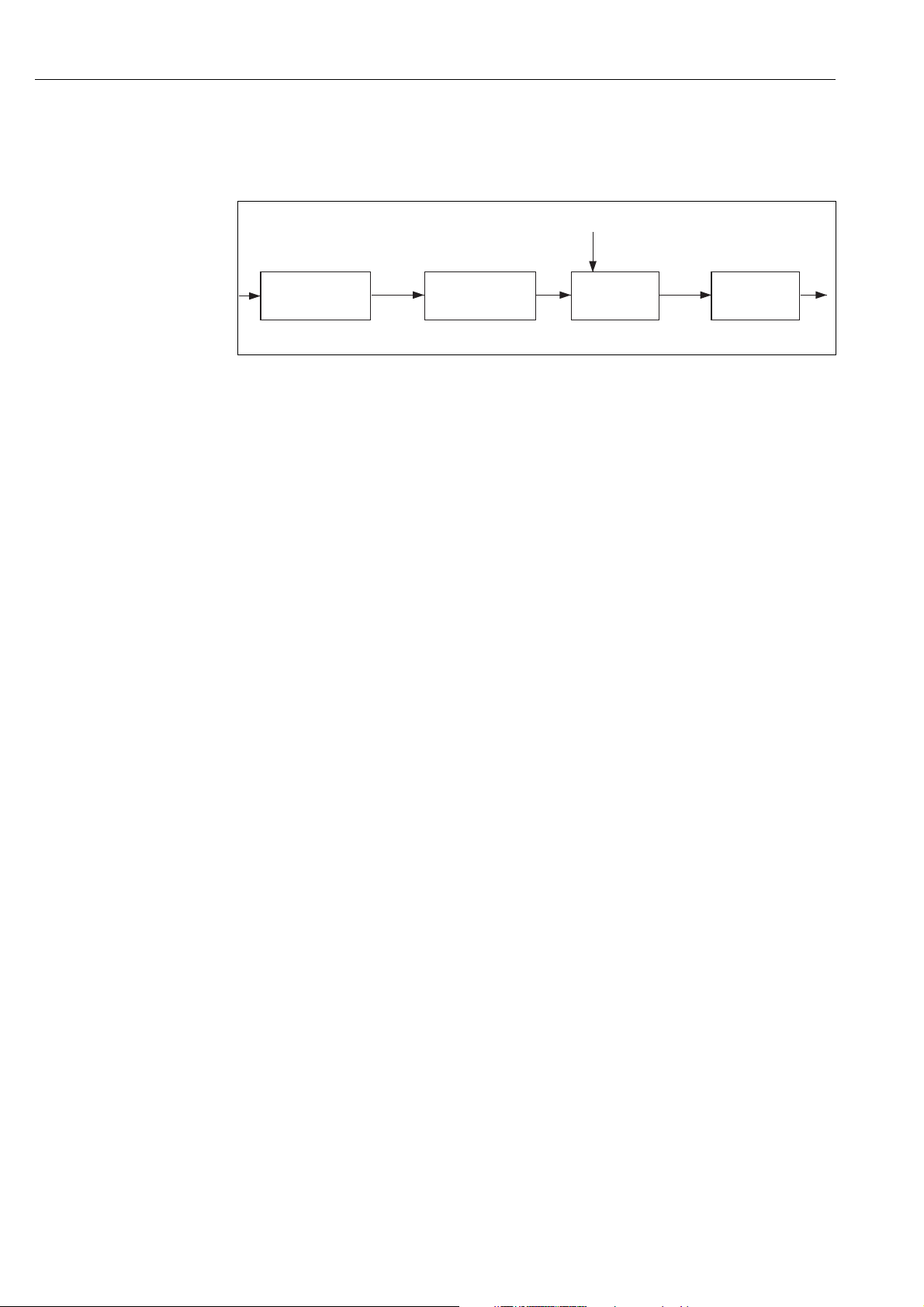
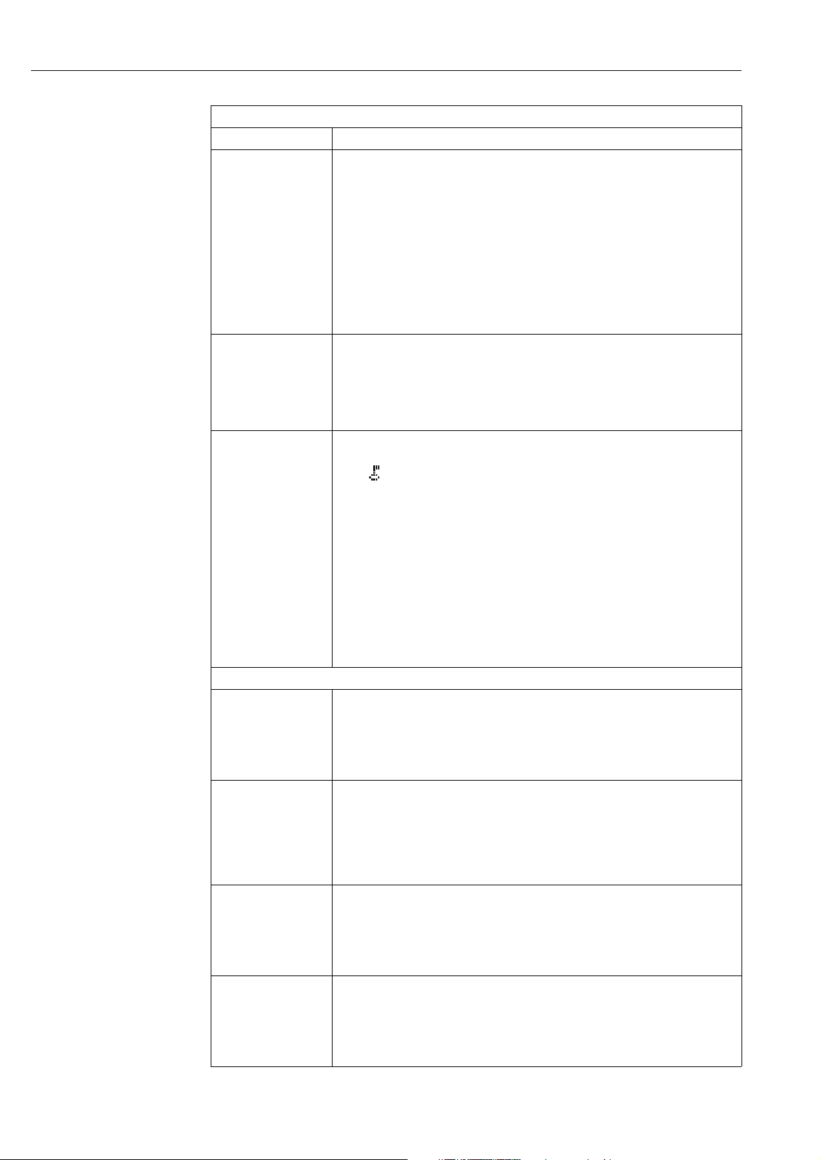
Block configuration when delivered
The block model shown below illustrates the block configuration when the device is delivered.
Measured variable
Sensor
Signal evaluation
Pressure
Transducer Block
Service
Transducer Block
Totalizer
Transducer Block
Display
Transducer Block
Diagnostic
Transducer Block
Fig. 7: Block configuration when delivered
Display
with scaling
Primary value
Secondary value
Deltabar only
TOTALIZER 1
Analog Input Block 1
CHANNEL = 1
L_TYPE = Direct
Analog Input Block 2
CHANNEL = 2
L_TYPE = Direct
Analog Input Block 3
CHANNEL = 6
L_TYPE = Direct
Arithmetic Block
Discrete Output
Block
Resource Block
PID Block
Signal Characterizer
Block
Input Selector Block
Analog Alarm Block
P01-xMx7xxxx-02-xx-xx-xx-000
!
Cerabar S
The Pressure Transducer Block returns the Primary Value (pressure measured value) and the
Secondary Value (sensor temperature). Primary Value and Secondary Value are each transferred to
one Analog Input Block by means of the CHANNEL parameter (→ see also Page 67, parameter
description CHANNEL).
The Discrete Output, PID, Arithmetic, Signal Characterizer, Input Selector and Analog Alarm Block
are not connected in the as-delivered state.
Deltabar S
The Pressure Transducer Block returns the Primary Value (pressure measured value) and the
Secondary Value (sensor temperature). In the Totalizer Transducer Block, the flow is totalized in
the "Flow" measuring mode and output by means of the TOTALIZER_1_VALUE/TOTALIZER 1
parameter. Primary Value, Secondary Value and TOTALIZER_1_VALUE are each transferred to one
Analog Input Block by means of the CHANNEL parameter (→ see also Page 67, parameter
description CHANNEL).
The Discrete Output, PID, Arithmetic, Signal Characterizer, Input Selector and Analog Alarm Block
are not connected in the as-delivered state.
Note!
Please note that the links between the blocks are deleted and the FF parameters are reset to the
default values following a reset by means of the RESTART parameter in the Resource Block,
"Default" option.
22 Endress+Hauser
Page 23

Cerabar S/Deltabar S Description of parameters (FF configuration program)
6.2 Resource Block
Resource Block
Parameter Description
ACK_OPTION
Selection
Index: 38
Data type: Bit String
Access: Auto, OOS
ALARM_SUM
Display, Selection
Index: 45
Data type: DS-74
Access: Auto, OOS
ALERT_KEY
Entry
Index: 4
Data type: Unsigned8
Access: Auto, OOS
BLOCK_ALM
Display, Selection
Index: 36
Data type: DS-72
Access: Auto, OOS
BLOCK_ERR
Display
Index: 6
Data type: Bit String
Access: Read only
Use this parameter to specify which process alarm is automatically acknowledged by the
fieldbus host system when it is detected. If the option is activated for a process alarm, this
process alarm is automatically acknowledged by the fieldbus host system.
Options:
• DiscAlm: write protection alarm
• BlockAlm: block alarm
Note!
!
For process alarms for which automatic confirmation is not active, the message must be
acknowledged by means of the BLOCK_ALM parameter, UNACKNOWLEDGE element.
Factory setting:
The option is not active for any process alarm, i.e. every process alarm message must be
acknowledged manually.
The ALARM_SUM parameter is a structured parameter consisting of four elements.
CURRENT
• Displays the current status of the process alarms in the Resource Block.
The following alarms are possible: DiscAlm and BlockAlm.
UNACKNOWLEDGED
• Displays the process alarms not confirmed.
UNREPORTED
• Displays the process alarms not reported.
DISABLED
• Possibility to deactivate process alarms.
Enter the identification number for the measuring device or for every individual block.
The host system uses this identification number to sort alarm and event messages and initiate
further processing.
Input range:
1...255
Factory setting:
0
The BLOCK_ALM parameter is a structured parameter consisting of five elements.
UNACKNOWLEDGED
• If the "Deactivated" option was selected for the alarm occurring via the ACK_OPTION
parameter, this alarm can only be acknowledged via this element.
ALARM_STATE
• Displays the current block status with information on the pending configuration, hardware
or system errors. The following block alarm messages are possible for the Resource Block:
–Simulate Active
–Out of Service
TIME_STAMP
• Displays the time the alarm occurred.
SUB_CODE
• Displays the reason why the alarm was reported.
VALUE
• Displays the value of the parameter at the time the alarm was reported.
Displays the active block errors.
Possibilities:
• Out Of Service: the Resource Block is in the OOS block mode.
• Simulation active: DIP switch 2 "Simulation" on the electronic insert is set to "On", i.e.
simulation is possible.
Endress+Hauser 23
Page 24
Description of parameters (FF configuration program) Cerabar S/Deltabar S
Resource Block
Parameter Description
CLR_FSTATE/
CLEAR FAULT STATE
Selection
Index: 30
Data type: Unsigned8
Access: Auto, OOS
CONFIRM_TIME
Entry
Index: 33
Data type: Unsigned32
Access: Auto, OOS
CYCLE_SEL
Display
Index: 20
Data type: Bit String
Access: Auto, OOS
CYCLE_TYPE
Display
Manually deactivate the fault state of the Discrete Output function block. → See also this
table, SET_FSTATE parameter description.
Possibilities:
• Uninititalized
•Off
• Clear (the fault state is deactivated.)
Enter the confirmation time for the event report. If the device does not receive any
confirmation within this period, the event report is sent again to the fieldbus host system.
Factory setting:
1
640000
/32 ms
Displays the block execution method used by the fieldbus host system. The fieldbus host
system selects the block execution method.
Possibilities:
• Scheduled: cyclical block execution method
• Block execution: sequential block execution method
Displays the block execution methods supported by the device. → See also this table,
CYCLE_SEL parameter description.
Index: 19
Data type: Bit String
Access: Read only
DD_REV
Display
Index: 13
Data type: Unsigned8
Access: Read only
DEV_REV
Display
Index: 12
Data type: Unsigned8
Access: Read only
DEV_TYPE
Display
Index: 11
Data type: Unsigned16
Access: Read only
FAULT_STATE
Display
Index: 28
Data type: Unsigned8
Access: Read only
FEATURES
Display
Displays the revision number of the device description (DD).
Displays the revision number of the device.
Displays the device identification number.
Deltabar S: hexadecimal: 1009, decimal: 4105.
Cerabar S: hexadecimal: 1007, decimal: 4103.
Current status display of the fault state of the Discrete Output function block.
Possibilities:
• Uninititalized
• Clear (fault state not active)
• Active (fault state active)
Displays the additional functions supported by the device. → See also this table,
FEATURE_SEL parameter description.
Index: 17
Data type: Bit String
Access: Read only
FEATURE_SEL/
FEATURE SELECTION
Selection
Index: 18
Data type: Bit String
Access: Auto, OOS
Select additional device functions. The additional functions the device supports is displayed in
the FEATURES parameter (→ Page 24).
24 Endress+Hauser
Page 25

Cerabar S/Deltabar S Description of parameters (FF configuration program)
Resource Block
Parameter Description
FREE_SPACE
Display
Index: 24
Data type: Float
Access: Read only
FREE_TIME
Display
Index: 25
Data type: Float
Access: Read only
GRANT_DENY
Selection
Index: 14
Data type: DS-70
Access: Auto, OOS
HARD_TYPES
Display
Displays in percent the system space available to execute further function blocks.
Input range:
0...100 %
Displays in percent the free system time available to execute further function blocks.
Input range:
0...100 %
Grant or restrict access rights for a fieldbus host system to the device. This parameter is not
evaluated by Deltabar S and Cerabar S.
Displays the input signal type for the Analog Input function blocks.
Index: 15
Data type: Bit String
Access: Read only
ITK_VER
Display
Index: 41
Data type: Unsigned16
Access: Read only
LIM_NOTIFY
Entry
Index: 32
Data type: Unsigned8
Access: Auto, OOS
MANUFAC_ID
Display
Index: 10
Data type: Unsigned16
Access: Read only
MAX_NOTIFY
Display
Index: 31
Data type: Unsigned8
Access: Read only
MEMORY_SIZE
Display
Displays the revision status of the ITKs (Interoperability Test Kit).
Enter the maximum possible number of event reports that can be simultaneously present as
unacknowledged. The parameter is not evaluated by Deltabar S and Cerabar S.
Displays the manufacturer identification number.
Endress+Hauser: 0 x 452B48 (decimal: 4533064)
Displays the number of event reports supported by the device that can be simultaneously
present as unacknowledged. → See also this table, LIM_NOTIFY parameter description.
Displays the configuration memory available in kilobyte. This parameter is not supported by
Deltabar S and Cerabar S.
Index: 22
Data type: DS-69
Access: Read only
MIN_CYCLE_T
Display
Index: 21
Data type: Unsigned32
Access: Read only
Displays the shortest execution time supported by the device.
Factory setting:
1
1600
/32 ms (≅ 50 ms)
Endress+Hauser 25
Page 26

Description of parameters (FF configuration program) Cerabar S/Deltabar S
Resource Block
Parameter Description
MODE_BLK
Selection, Display
Index: 5
Data type: DS-69
Access: Auto, OOS
NV_CYCLE_T/
NONVOLATILE CYCLE
TIME
Display
Index: 23
Data type: Unsigned32
Access: Read only
RESTART
Selection
Index: 16
Data type: Unsigned8
Access: Auto, OOS
RS_STATE
Display
Index: 7
Data type: Unsigned8
Access: Read only
SET_FSTATE/
SET FAULT STATE
Selection
Index: 29
Data type: Unsigned8
Access: Auto, OOS
SHED_RCAS/
SHED REMOTE
CASCADE
Entry
Index: 26
Data type: Unsigned32
Access: Auto, OOS
SHED_ROUT/
SHED REMOTE OUT
Entry
Index: 27
Data type: Unsigned32
Access: Auto, OOS
The MODE_BLK parameter is a structured parameter consisting of four elements.
The Resource Block supports the "Auto" (automatic mode) and OOS (out of service) modes.
TARGET
• Change the block mode.
ACTUAL
• Displays the current block mode.
PERMITTED
• Displays the modes supported by the block.
NORMAL
• Displays the block mode during standard operation.
Displays the time interval in which the dynamic device parameters are stored in the nonvolatile memory. As Cerabar S and Deltabar S do not store dynamic device parameters in the
non-volatile memory, the parameter constantly displays the value 0
1
/32 ms.
Select reset mode.
Options:
• Run: standard operating mode
• Resource: this mode is not supported by Endress+Hauser.
• Defaults: device data and the function block link are reset to the factory setting. The
manufacturer-specific parameters of the Transducer Block are not reset to the factory
setting.
→ See also Operating Instructions BA301P (Deltabar S) or BA302P (Cerabar S),
Section 5.7 "Factory setting" (reset).
• Processor: warm start, of device, new processor start.
• Factory: the function block links, all FF and resettable manufacturer-specific parameters
are reset to the factory setting.
Displays the current status of the Resource Block.
Possibilities:
• Standby: the Resource Block is in the OOS mode (out of service). It is not possible to
execute the remaining blocks.
• Online linking: the configured links between the function blocks have not yet been
established.
• Online: standard block mode, the Resource Block works in the Auto mode. All the
configured links between the function blocks have been established. If a link is missing,
this parameter displays the "online linking" status.
Manually activate the fault state of the Discrete Output function block. → See also this table,
CLR_FSTATE parameter description.
Possibilities:
• Uninititalized
•Off
• Set (the fault state is activated.)
Enter the monitoring time for checking the link between the fieldbus host system and the
PID function block in the RCAS block mode. Once this monitoring time elapses, the PID
function block changes from the RCAS block mode to the block mode selected by means of
the SHED_OPT parameter.
Factory setting:
1
640000
/32 ms
Enter the monitoring time for checking the link between the fieldbus host system and the
PID function block in the ROUT block mode. Once this monitoring time elapses, the PID
function block changes from the ROUT block mode to the block mode selected by means of
the SHED_OPT parameter.
Factory setting:
1
640000
/32 ms
26 Endress+Hauser
Page 27
Cerabar S/Deltabar S Description of parameters (FF configuration program)
Resource Block
Parameter Description
ST_REV
Display
Index: 1
Data type: Unsigned16
Access: Read only
STRATEGY
Entry
Index: 3
Data type: Unsigned16
Access: Auto, OOS
TAG_DESC
Entry
Index: 2
Data type: Octet String
Access: Auto, OOS
TEST_RW/
TEST READ WRITE
Display
Index: 8
Data type: DS-85
Access: Auto, OOS
UPDATE_EVT
Display
Index: 35
Data type: DS-73
Access: Read only
WRITE_ALM
Display
Index: 40
Data type: DS-72
Access: Read only
Displays the counter for static parameters of the Resource Block
This counter is incremented by one with each change of a static parameter of the Resource
Block. The counter counts up to 65535 and then starts again at zero.
Enter a user-specific value for grouping and thus faster evaluation of the blocks.
Grouping takes place by entering the same numerical value for the STRATEGY parameter of
the block in question. This value is neither checked nor processed by the Resource Block.
Input range:
0...65535
Factory setting:
0
Enter a description for the associated block or the measuring point e.g. TAG number (max.
32 alphanumeric characters).
This parameter is only needed for the FF conformance test and does not have any relevance
during measuring operation.
The UPDATE_EVT parameter is a structured parameter consisting of five elements.
UNACKNOWLEDGED
• This element is set to "Unacknowledged" as soon as a static parameter changes.
UPDATE_STATE
• Displays whether the change was reported.
TIME_STAMP
• Displays the date and time a static parameter was changed.
STATIC_REVISION
• The revision counter is increased when a static parameter changes.
RELATIVE_INDEX
• Displays the altered parameter in the form of the relative index. See also this table,
"Parameter, Index" column.
The WRITE_ALM parameter is a structured parameter consisting of five elements.
UNACKNOWLEDGED
• If the "Deactivated" option was selected for the alarm occurring via the ACK_OPTION
parameter, this alarm can only be acknowledged via this element.
ALARM_STATE
• Status display of the write protection alarm.
TIME_STATE
• Displays the time the alarm occurred.
SUB_CODE
• Displays the reason why the alarm was reported.
VALUE
• Displays the value of the parameter at the time the alarm was reported.
Endress+Hauser 27
Page 28
Description of parameters (FF configuration program) Cerabar S/Deltabar S
Resource Block
Parameter Description
WRITE_LOCK
Display
Index: 34
Data type: Unsigned8
Access: Read only
WRITE_PRI
Entry
Index: 39
Data type: Unsigned8
Access: Read only
SW_LOCK/
INSERT PIN No.
Entry
Index: 43
Data type: Unsigned16
Access: Auto, OOS
Endress+Hauser Resource Block parameters
DEVICE_DIALOG
Display
Index: 42
Data type: Unsigned8
Access: Read only
DEVICE_ORDER_CODE
/DEVICE DESIGN.
Display
Displays the status of DIP switch 1 on the electronic insert.
You can lock and unlock parameters relevant to the measured value with DIP switch 1. If
operation is locked by means of the SW_LOCK/INSERT PIN No. parameter (→ see Page 28),
you can only unlock operation again by means of this parameter. → See also Operating
Instructions BA301P (Deltabar S) or BA302P (Cerabar S), Section 5.6 "Locking/unlocking
operation".
Possibilities:
• Locked: locking switched on, i.e. the parameters cannot be written to.
• Not Locked: locking switched off. Depending on the block mode in question, the
parameters can be written to (→ see tables, "Parameter", Access column).
Factory setting:
Locked (locking switched off)
Disabling write protection generates an alarm. Use this parameter to specify which priority
should be assigned to this alarm.
Input range:
• 0...15
• 0: The alarm is suppressed.
• 15: Critical alarm with the highest priority.
For entering a code to lock or unlock operation.
Note!
!
• The symbol on the on-site display indicates that operation is locked. Parameters which
refer to how the display appears, e.g. LANGUAGE and DISPLAY CONTRAST can still be
altered.
• If operation is locked by means of the DIP-switch, you can only unlock operation again by
means of the DIP-switch. If operation is locked by means of remote operation, you can
only unlock operation again by means of remote operation.
→ See also Operating Instructions BA301P (Deltabar S) or BA302P (Cerabar S), Section 5.6
"Locking/unlocking operation".
Options:
• Lock: enter a number between 0...9999 which is ≠100.
• Unlock: enter number 100.
Factory setting:
100
If the configuration is not suitable, this parameter displays a message saying that a
configuration error is present. The message can indicate which parameter was incorrectly
configured.
Displays the device designation and the order code.
Index: 44
Data type: Visible String
Access: Read only
HARDWARE_REVISION
Display
Index: 45
Data type: Visible String
Access: Read only
SOFTWARE_VERSION
Display
Index: 46
Data type: Float
Access: Read only
Displays the revision number of the main electronics e.g. V01.00.
Displays the software version e.g. V02.00.
28 Endress+Hauser
Page 29

Cerabar S/Deltabar S Description of parameters (FF configuration program)
Resource Block
Parameter Description
ELECTRONIC _SERIAL
_NUMBER/
ELECTR. SERIAL No.
Display
Index: 47
Data type: Float
Access: Read only
DEVICE_SERIAL_
NUMBER/
DEVICE SERIAL No.
Display
Index: 48
Data type: Float
Access: Read only
PROCESS_CONNECTION_MODEL/
PROC. CONN. TYPE
Selection
Index: 49
Data type: Unsigned16
Access: Auto, OOS
PROCESS_CONNECTION_MATERIAL_
POSITIVE/
MAT. PROC. CONN. +
Selection
Index: 50
Data type: Float
Access: Auto, OOS
PROCESS_CONNECTION_MATERIAL_
NEGATIVE/
MAT.PROC. CONN.–
Selection
Displays the serial number of the main electronics (11 alphanumeric characters).
Displays the serial number of the device (11 alphanumeric characters).
For selecting and displaying the process connection type.
Options:
•Not used
•Unknown
•Special
•Oval flange
• Thread female
•Thread male
•Flange
•Remote seal
For selecting and displaying the material of the process connection (P+).
→ See also parameter description MAT. PROC. CONN. –
Options:
•Not used
•Unknown
•Special
• Steel
• 304 st. steel
• 316 st. steel
• Alloy C
•Monel
•Tantalum
• Titanium
•PTFE (Teflon)
• 316L st. steel
•PVC
•Inconel
•PVDF
•ECTFE
Factory setting:
As per order specifications
For selecting and displaying the material of the process connection (P–).
→ See also parameter description MAT. PROC. CONN. +
Index: 51
Data type: Float
Access: Auto, OOS
Endress+Hauser 29
Page 30

Description of parameters (FF configuration program) Cerabar S/Deltabar S
Resource Block
Parameter Description
PROCESS_FLANGE_
GASKET_MATERIAL/
SEAL TYPE
Selection
Index: 52
Data type: Visible String
Access: Auto, OOS
SCI_OCTET_STR
Display
For displaying and selecting the material of the process seal.
Options:
•Not used
•Unknown
•Special
• FKM Viton
•NBR
•EPDM
•Urethane
•IIR
•Kalrez
• FKM Viton oxyg
•CR
•MVQ
•PTFE glass
•PTFE graphite
• PTFE oxygen
• Copper
• Copper f. oxygen
Factory setting:
As per order specifications
Internal service parameter.
Index: 53
Data type: Visible String
Access: Read only
30 Endress+Hauser
Page 31

Cerabar S/Deltabar S Description of parameters (FF configuration program)
6.3 Transducer Blocks
6.3.1 FOUNDATION Fieldbus standard parameters Transducer Blocks
Transducer Block, FOUNDATION Fieldbus standard parameters (all Transducer Blocks)
Parameter Description
ST_REV
Display
Index: 1
Data type: Usigned16
Access: Read only
TAG_DESC
Entry
Index: 2
Data type: Octet String
Access: Auto, OOS
STRATEGY
Entry
Index: 3
Data type: Unsigned16
Access: Auto, OOS
ALERT_KEY
Entry
Index: 4
Data type: Unsigned8
Access: Auto, OOS
MODE_BLK
Display, Selection
Index: 5
Data type: DS-69
Access: Auto, OOS
BLOCK_ERR
Display
Index: 6
Data type: Bit String
Access: Read only
Displays the counter for the static parameters of the Transducer Block
This counter is increased by one with each change to a static parameter of the Transducer
Block in question. The counter counts to 65535 and then starts again at zero.
Enter a description for the associated block or the measuring point e.g. TAG number
(max. 32 alphanumeric characters).
Factory setting:
Empty field
Enter a user-specific value for grouping and thus faster evaluation of the blocks.
Grouping takes place by entering the same numeric value for the STRATEGY parameter of
the block in question. These data are neither checked nor processed by the Transducer
Blocks.
Input range:
0...65535
Factory setting:
0
Enter the identification number for the device or for each individual block.
The host system uses this identification number to sort alarm and event messages and initiate
further processing.
Input range:
1...255
Factory setting:
0
The MODE_BLK parameter is a structured parameter consisting of four elements.
The Transducer Blocks support the "Auto" (automatic mode) and OOS
(out of service) modes.
TARGET
• Change the block mode.
ACTUAL
• Displays the current block mode.
PERMITTED
• Displays the modes supported by the block.
NORMAL
• Displays the block mode during standard operation.
Note!
!
Measured values or information can be forwarded to an Analog Input Block by means of the
Pressure, Service and Totalizer Transducer Block. If the Pressure Transducer Block is set to
the OOS block mode, for example, the primary and secondary value continue to be updated
but the status of the downstream Analog Input Block changes to BAD.
Displays the warning and error messages of the software and hardware of the Transducer
Block in question. This parameter also triggers an alarm. If two or more messages occur at the
same time, the message with the highest priority is the one shown on the display.
For the Pressure, Service and Totalizer Block, see possible messages in these Operating
Instructions, Section 11.1 "Messages". The Display and Diagnostic Blocks do not display any
warning or error messages.
Endress+Hauser 31
Page 32

Description of parameters (FF configuration program) Cerabar S/Deltabar S
Transducer Block, FOUNDATION Fieldbus standard parameters (all Transducer Blocks)
Parameter Description
UPDATE_EVT
Display
Index: 7
Data type: DS-73
Access: Read only
BLOCK_ALM
Display, Selection
Index: 8
Data type: DS-72
Access: Auto, OOS
TRANSDUCER_
DIRECTORY
Display
Index: 9
Data type: Unsigned16
Access: Read only
TRANSDUCER_TYPE
Display
Index: 10
Data type: Unsigned16
Access: Read only
XD_ERROR
Display
Index: 11
Data type: Usigned8
Access: Read only
COLLECTION_
DIRECTORY
Display
Index: 12
Data type: Unsigned32
Access: Read only
The UPDATE_EVT parameter is a structured parameter consisting of five elements.
UNACKNOWLEDGED
• This element is set to "Unacknowledged" as soon as a static parameter changes.
UPDATE_STATE
•Displays whether the change was reported.
TIME_STAMP
• Displays the date and time a static parameter was changed.
STATIC_REVISION
• The revision counter is increased when a static parameter changes.
RELATIVE_INDEX
• Displays the altered parameter in the form of the relative index. See also this table,
"Parameter, Index" column.
The BLOCK_ALM parameter is a structured parameter consisting of five elements.
UNACKNOWLEDGED
• If the "Deactivated" option was selected for the alarm occurring via the ACK_OPTION
parameter, this alarm can only be acknowledged via this element.
ALARM_STATE
• Displays the current block status with information on the pending configuration, hardware
or system errors.
TIME_STAMP
• Displays the date and time the alarm occurred.
SUB_CODE
• Displays the reason why the alarm was reported.
VALUE
• Displays the value of the parameter at the time the alarm was reported.
A directory that specifies the number of transducers mapped in the Pressure Transducer
Block and their indices. This parameter is only displayed in the Pressure Transducer Block.
Display:
0: Only one transducer is mapped in the Pressure Transducer Block.
Displays the Transducer Block type.
Displays the active device status.
→ See also these Operating Instructions, Section 11.1 "Messages".
Prerequisite:
• Pressure Transducer Block
• Service Transducer Block
• Totalizer Transducer Block (only Deltabar S)
A directory that specifies the number of parameter groups (data collection) mapped in the
Pressure Transducer, their indices and DD item IDs. This parameter is only displayed in the
Pressure Transducer Block.
Display:
0: This parameter is not used.
32 Endress+Hauser
Page 33

Cerabar S/Deltabar S Description of parameters (FF configuration program)
6.3.2 Pressure Transducer Block
Pressure Transducer Block
Parameter Description
PRIMARY_VALUE_TYPE
Selection
Index: 13
Data type: Unsigned16
Access: OOS
PRIMARY_VALUE
Display
Index: 14
Data type: DS-65
Access: Read only
PRIMARY_VALUE_
RANGE
Display
Index: 15
Data type: DS-68
Access: Read only
CAL_POINT_HI/
HIGH SENSOR TRIM
Entry
Index: 16
Data type: Float
Access: OOS
Use this parameter and the LINEARIZATION parameter (→ Page 36) to select the measuring
mode and the measured variable.
→ See also Operating Instructions Deltabar S (BA301P) and Cerabar S (BA302P), select
Section 6.3 "Language and measuring mode".
Selection
• Differential pressure with Deltabar S
• Gauge pressure with Cerabar S with absolute pressure sensors.
• Absolute pressure with Cerabar S with overpressure sensors.
• Level
•Volume
•Mass
• Flow (only Deltabar S)
• Tank content (PV) in %
Note!
!
Make sure that the unit selected by means of the SCALE_OUT parameter, "Units Index"
element, matches the measured variable.
The PRIMARY_VALUE parameter is a structured parameter consisting of two elements.
VALUE
• Displays the primary value, which, depending on the measuring mode, is a pressure, level
or flow value.
STATUS
• Displays the status of the primary value.
Note!
!
You can transfer the value and status of the PRIMARY_VALUE parameter via the CHANNEL
parameter (→ Page 67) in the Analog Input Block. For this purpose, the CHANNEL must be
set to "1".
The PRIMARY_VALUE_RANGE parameter is a structured parameter consisting of four
elements.
EU_100
• Displays the upper limit for the primary value.
EU_0
• Displays the lower limit for the primary value.
UNITS_INDEX
• Displays the unit.
DECIMAL
• Displays the number of places after the decimal point.
Note!
!
The PRIMARY_VALUE_RANGE parameter corresponds to the SCALE_OUT parameter
(→ Page 37).
Enter the upper point of the response curve during sensor recalibration.
You can use this parameter to assign a new target pressure value to a reference pressure
present at the device. The pressure value present and the target pressure value specified for
this parameter correspond to the upper point in the response curve. Position adjustment must
be carried out on the device following sensor recalibration.
Note!
!
• Using the "High Sensor Trim" method in the Pressure Transducer Block, you can carry out
dialog-guided sensor recalibration of the upper point of the response curve.
• Sensor recalibration can be reset by means of the RESET_INPUT_VALUE/ENTER RESET
CODE parameter (→ Page 64) with the code "2509".
• The PRESSURE_1_UPPER_CAL_MEASURED/HI TRIM MEASURED parameter
(→ Page 39) displays the pressure value that was present at the device during the
calibration and was used for calibrating the upper point of the response curve.
• For calibrating the lower point of the response curve, see parameter description for
CAL_POINT_LO/LOW SENSOR TRIM.
Factory setting: upper measuring limit (→ SENSOR_RANGE, EU_100 element)
Endress+Hauser 33
Page 34

Description of parameters (FF configuration program) Cerabar S/Deltabar S
Pressure Transducer Block
Parameter Description
CAL_POINT_LO/
LOW SENSOR TRIM
Entry
Index: 17
Data type: Float
Access: OOS
CAL_MIN_SPAN/
MINIMUM SPAN
Display
Index: 18
Data type: Float
Access: OOS
CAL_UNIT
Entry
Index: 19
Data type: Unsigned16
Access: OOS
SENSOR_TYPE
Selection
Enter the lower point of the response curve during sensor recalibration.
You can use this parameter to assign a new target pressure value to a reference pressure
present at the device. The pressure value present and the target pressure value specified for
this parameter correspond to the lower point in the response curve. Position adjustment must
be carried out on the device following sensor recalibration.
Note!
!
• Using the "Low Sensor Trim" method in the Pressure Transducer Block, you can carry out
dialog-guided sensor recalibration of the lower point of the response curve.
• Sensor recalibration can be reset by means of the RESET_INPUT_VALUE/ENTER RESET
CODE parameter (→ Page 64) with the code "2509".
• The PRESSURE_1_LOWER_CAL_MEASURED/LO TRIM MEASURED parameter
(→ Page 39) displays the pressure value that was present at the device during the
calibration and was used for calibrating the lower point of the response curve.
• For calibrating the upper point of the response curve, see parameter description for
CAL_POINT_HI/HIGH SENSOR TRIM.
Factory setting: lower measuring limit (→ SENSOR_RANGE, EU_0 element)
Displays the smallest possible span.
Select pressure unit.
If a new pressure unit is selected, all pressure-specific parameters are converted and displayed
with the new unit.
Selection
• mbar, bar
• mmH
O, mH2O, inH2O, ftH2O
2
• Pa, hPa, kPa, MPa
•psi
• mmHg, inHg
•Torr
2
, kg/cm
2
, kgf/cm
2
2
• g/cm
2
•lb/ft
•atm
•gf/cm
•User unit, → See also parameter description for PRESSURE_1_UNIT_TEXT/CUSTOMER
UNIT P (Page 39) and PRESSURE_1_UNIT_SCALE/CUST. UNIT FACT. P
(Page 39).
Factory setting:
Depends on the sensor nominal measuring range mbar or bar or as per order specifications
Displays the sensor type.
Index: 20
Data type: Unsigned16
Access: OOS
SENSOR_RANGE
Display
Index: 21
Data type: DS-68
Access: Read only
The SENSOR_RANGE parameter is a structured parameter consisting of four elements.
EU_100
• Displays the upper measuring limit of the sensor.
EU_0
• Displays the lower measuring limit of the sensor.
UNITS_INDEX
• Displays the unit selected.
DECIMAL
• Displays the number of places after the decimal point.
34 Endress+Hauser
Page 35

Cerabar S/Deltabar S Description of parameters (FF configuration program)
Pressure Transducer Block
Parameter Description
SENSOR_SN/
SENSOR SER. No.
Display
Index: 22
Data type: Visible String
Access: Read only
SENSOR_CAL_METHOD
Selection
Index: 23
Data type: Unsigned8
Access: OOS
SENSOR_CAL_LOC
Entry
Index: 24
Data type: Visible String
Access: OOS
SENSOR_CAL_DATE
Entry
Displays the serial number of the sensor (11 alphanumeric characters).
For displaying and selecting the last sensor calibration method used.
Enter the location where the sensor was calibrated (32 alphanumeric characters).
Enter the date and time the sensor was calibrated.
Index: 25
Data type: Date
Access: OOS
SENSOR_CAL_WHO
Entry
Index: 26
Data type: Visible String
Access: OOS
SENSOR_ISOLATOR_
MTL
Display
Index: 27
Data type: Unsigned16
Access: Read only
SENSOR_FILL_FLUID
Display
Index: 28
Data type: Unsigned16
Access: Read only
SECONDARY_VALUE
Display
Index: 29
Data type: DS-65
Access: Read only
SECONDARY_VALUE_
UNIT
Selection
Enter the name of the person who calibrated the sensor (32 alphanumeric characters).
Displays the membrane material.
Displays the filling fluid.
The SECONDARY_VALUE parameter is a structured parameter consisting of two elements.
VALUE
• Displays the second process value, here the sensor temperature.
STATUS
• Displays the status of the second process value.
Note!
!
You can transfer the value and status of the SECONDARY_VALUE parameter via the
CHANNEL parameter (→ Page 67) in the Analog Input Block. For this purpose, the
CHANNEL must be set to "2".
Select the unit for the second process value.
→ See also parameter description for SECONDARY_VALUE.
Index: 30
Data type: Unsigned16
Access: Auto, OOS
Endress+Hauser 35
Page 36

Description of parameters (FF configuration program) Cerabar S/Deltabar S
Pressure Transducer Block
Parameter Description
DEVICE_DIALOG
Display
Index: 31
Data type: Unsigned8
Access: Read only
LINEARIZATION
Selection
Index: 32
Data type: Unsigned8
Access: OOS
SCALE_IN
Entry
Index: 33
Data type: DS-65
Access: Auto, OOS
If the configuration is not suitable, this parameter displays a message saying that a
configuration error is present. The message can indicate which parameter was incorrectly
configured.
Use this parameter and the PRIMARY_VALUE_TYPE parameter (→ Page 33) to select the
measuring mode and the measured variable.
→ See also Operating Instructions Deltabar S (BA301P) and Cerabar S (BA302P), select
Section 6.3 "Language and measuring mode".
Options:
• No linearisation ("Pressure" or "Level" measuring mode)
• Level linearized ("Level" measuring mode)
• Level combined ("Level" measuring mode)
• % Level combined ("Level" measuring mode)
• Flow square root ("Flow" measuring mode)
The option selected in this parameter can also have an effect on the setting of the
LEVEL_TYPE/LEVEL MODE parameter (→ Page 40). For example, if "Level linearized" is
selected, the LEVEL_TYPE/LEVEL MODE parameter is set to the "Pressure linearized"
option.
Note!
!
Make sure that the unit selected by means of the SCALE_OUT parameter, "Units Index"
element, matches the measured variable.
The SCALE_IN parameter is a structured parameter consisting of four elements.
EU_100
• "Pressure" measuring mode; "Level" measuring mode, "Linear" or "Height linearized" level
mode: enter upper limit for the pressure value of the Transducer Block.
• "Level" measuring mode, "Pressure linearized" level mode:
Enter the maximum hydrostatic pressure to be expected.
The input limits for the calibration (editing limits) are derived from the value entered. The
closer the value entered corresponds to the maximum hydrostatic pressure to be expected,
the more accurate the measurement result.
• "Flow" measuring mode: enter maximum pressure of primary device.
→ See layout sheet of primary device. This value is assigned to the maximum flow value
(→ See following SCALE_OUT parameter, EU_100 element).
• Factory setting: upper measuring limit of the sensor
EU_0
• "Pressure" measuring mode; "Level" measuring mode, "Linear" or "Height linearized" level
mode, "Flow" measuring mode: enter lower limit for the pressure value of the Transducer
Block.
• "Level" measuring mode, "Pressure linearized" level mode:
Enter the minimum hydrostatic pressure to be expected.
The input limits for the calibration (editing limits) are derived from the value entered. The
closer the value entered corresponds to the minimum hydrostatic pressure to be expected,
the more accurate the measurement result.
•Factory setting: 0
UNITS_INDEX
• Select the unit for input scaling.
DECIMAL
• Enter the number of places after the decimal point.
36 Endress+Hauser
Page 37

Cerabar S/Deltabar S Description of parameters (FF configuration program)
Pressure Transducer Block
Parameter Description
SCALE_OUT
Entry
Index: 34
Data type: DS-68
Access: OOS
ACTIVE_ PRESSURE
_1_DAMPING/
DAMPING VALUE
Entry
Index: 35
Data type: Float
Access: Auto, OOS
TOTALIZER_1_FLOAT/
TOTALIZER 1
Display
Index: 36
Data type: Float
Access: Read only
TOTALIZER_2_FLOAT/
TOTALIZER 2
Display
Index: 37
Data type: Float
Access: Read only
The SCALE_OUT parameter is a structured parameter consisting of four elements.
EU_100
• "Pressure" measuring mode; "Level" measuring mode, "Linear" level mode: enter upper
limit for the output value of the Transducer Block.
Factory setting: 100
• "Level" measuring mode, "Pressure linearized" or "Height linearized" level mode:
Enter the maximum tank contents to be expected.
The input limits for the subsequent calibration (editing limits) are derived from the value
entered. The closer the value entered corresponds to the maximum tank content to be
expected, the more accurate the measurement result.
Factory setting: 100
• "Flow" measuring mode: enter maximum flow of primary device.
See also layout sheet of primary device. The maximum flow is assigned to the maximum
pressure which you enter by means of the SCALE_IN parameter, EU_100 element.
Factory setting: 1.0
EU_0
• "Pressure" measuring mode; "Level" measuring mode, "Linear" level mode; "Flow"
measuring mode: enter lower limit for the output value of the Transducer Block.
• "Level" measuring mode, "Pressure linearized" or "Height linearized" level mode:
Enter the minimum tank contents to be expected.
The input limits for the calibration (editing limits) are derived from the value entered. The
closer the value entered corresponds to the minimum tank content to be expected, the
more accurate the measurement result.
•Factory setting: 0
UNITS_INDEX
• Select the unit for output scaling.
DECIMAL
• Enter the number of places after the decimal point.
Note!
!
Make sure that the unit selected by means of the SCALE_OUT parameter, "Units Index"
element, matches the measured variable. → See also parameter description for
PRIMARY_VALUE_TYPE (Page 33) and LINEARIZATION (Page 36).
Enter damping time (time constant τ).
The damping affects the speed at which all subsequent elements, such as the on-site display,
measured value (primary value) and output value of the Analog Input Block react to a change
in the pressure.
Input range:
0.0...999.0 s
Factory setting:
2.0 s or as per order specifications
Displays the total flow value of totalizer 1. You can reset the value by means of the
TOTALIZER_1_RESET/RESET TOTALIZER 1 parameter (→ Page 59) in the Totalizer
Transducer Block.
Prerequisite:
• Deltabar S differential pressure transmitter
Displays the total flow value of totalizer 2. You cannot reset totalizer 2.
Prerequisite:
• Deltabar S differential pressure transmitter
Endress+Hauser 37
Page 38

Description of parameters (FF configuration program) Cerabar S/Deltabar S
Pressure Transducer Block
Parameter Description
PRESSURE_1_ACCEPT_
ZERO_INSTALL_OFFSET
/POS. ZERO ADJUST
Selection
Index: 38
Data type: Unsigned8
Access: Auto, OOS
PRESSURE_1_ACCEPT_
INSTALL_OFFSET/
POS. INPUT VALUE
Entry
Index: 39
Data type: Float
Access: Auto, OOS
PRESSURE_1_INSTALL_
OFFSET/
CALIB. OFFSET
Entry
Index: 40
Data type: Float
Access: Auto/OOS
Due to the orientation of the device, there may be a shift in the measured value, i.e. for
example, when the container is empty, the PRIMARY_VALUE parameter does not display
zero.
This parameter gives the user the opportunity to perform position adjustment where the
pressure difference between zero (set point) and the measured pressure need not be known.
(A reference pressure is present at the device.)
Example:
– PRIMARY_VALUE = 2.2 mbar
– You correct the PRIMARY VALUE via the
PRESSURE_1_ACCEPT_ZERO_INSTALL_OFFSET parameter with the "Confirm" option.
This means that you are assigning the value 0.0 to the pressure present.
– PRIMARY_VALUE (after pos. zero adjust) = 0.0 mbar
The PRESSURE_1_INSTALL_OFFSET/CALIB. OFFSET parameter (→ Page 38) displays the
resulting pressure difference (offset) by which the PRIMARY_VALUE was corrected.
Options::
• Abort
•Confirm
Factory setting:
0
Due to the orientation of the device, there may be a shift in the measured value, i.e. for
example, when the container is empty, the PRIMARY_VALUE parameter does not display
zero or the desired value.
This parameter gives the user the opportunity to perform position adjustment where the
pressure difference between zero (set point) and the measured pressure need not be known.
(A reference pressure is present at the device.)
Example:
– PRIMARY_VALUE = 0.5 mbar
– For the PRESSURE_1_ACCEPT_INSTALL_OFFSET parameter, specify the desired set
point for the PRIMARY_VALUE e.g. 2 mbar.
(PRIMARY_VALUE
– PRIMARY_VALUE (after entry for PRESSURE_1_ACCEPT_INSTALL_OFFSET)
= PRESSURE_1_ACCEPT_INSTALL_OFFSET)
new
= 2.0 mbar
– The PRESSURE_1_INSTALL_OFFSET/CALIB. OFFSET parameter (→ Page 38) displays
the resulting pressure difference (offset) by which the PRIMARY_VALUE was corrected.
(PRESSURE_1_INSTALL_OFFSET =
PRIMARY_VALUE
here: PRESSURE_1_INSTALL_OFFSET = 0.5 mbar – 2.0 mbar = – 1.5 mbar)
– PRESSURE_1_ACCEPT_INSTALL_OFFSET,
old
Factory setting:
0.0
Due to the orientation of the device, there may be a shift in the measured value, i.e. for
example, when the container is empty, the PRIMARY_VALUE parameter does not display
zero or the desired value.
This parameter gives the user the opportunity to perform position adjustment where the
pressure difference between zero (set point) and the measured pressure is known. (A
reference pressure is not present at the device.)
Example:
– PRIMARY_VALUE = 2.2 mbar
– Use the PRESSURE_1_INSTALL_OFFSET parameter to enter the value by which the
PRIMARY_VALUE should be corrected. To correct the PRIMARY_VALUE to 0.0 mbar,
you must enter the value 2.2 here.
(PRIMARY_VALUE
PRIMARY_VALUE
– PRIMARY_VALUE (after entry for calib. offset) = 0.0 mbar
=
new
– PRESSURE_1_INSTALL_OFFSET)
old
Factory setting:
0.0
38 Endress+Hauser
Page 39

Cerabar S/Deltabar S Description of parameters (FF configuration program)
Pressure Transducer Block
Parameter Description
PRESSURE_1_UNIT_
TEXT/
CUSTOMER UNIT P
Entry
Index: 41
Data type: Visible String
Access: Auto, OOS
PRESSURE_1_UNIT_
SCALE/
CUST. UNIT FACT. P.
Entry
Index: 42
Data type: Float
Access: Auto, OOS
PRESSURE_1_LOWER_
CAL_MEASURED/
LO TRIM MEASURED
Display
Enter text (unit) for customer-specific pressure unit.
You can enter a maximum of eight alphanumeric characters here. → See also
PRESSURE_1_UNIT_SCALE/CUST. UNIT FACT. P.
Prerequisite:
•CAL_UNIT (→ Page 34) = user unit
Note!
!
Only the first five characters are shown on the on-site display. For example, if "crates" is
specified as the customer-specific unit, "crate" is displayed.
If the unit contains a slash, up to eight characters can be shown on the on-site display. The
maximum number of characters in the counter is again limited to five. For example, if
"crates/m2" is specified as the customer-specific unit, "crate/m2" is displayed. In the FF
configuration program, the slash counts as a character, i.e. "crates/m2" would be displayed as
"crates/m".
Factory setting:
_ _ _ _ _ _ _ _
Enter conversion factor for a customer-specific pressure unit.
The conversion factor must be entered in relation to the SI unit "Pa".
→ See also PRESSURE_1_UNIT_TEXT/CUSTOMER UNIT P.
Prerequisite:
•CAL_UNIT (→ Page 34) = user unit
Example:
– You want the measured value to be displayed in "PU" (PU: packing unit).
– PRIMARY_VALUE =10000 Pa i 1 PU
– Entry PRESSURE_1_UNIT_TEXT/CUSTOMER UNIT P: PU
– Entry PRESSURE_1_UNIT_SCALE/CUST. UNIT FACT. P: 0.0001
– Result: PRIMARY_VALUE = 1 PU
Factory setting:
1.0
Displays the pressure that was present at the device during the calibration and which was
used for calibrating the lower point of the response curve. → See also parameter description
for CAL_POINT_LO/LOW SENSOR TRIM (→ Page 34).
Index: 43
Data type: Float
Access: Read only
PRESSURE_1_UPPER_
CAL_MEASURED/
HI TRIM MEASURED
Display
Index: 44
Data type: Float
Access: Read only
Displays the pressure that was present at the device during the calibration and which was
used for calibrating the upper point of the response curve. → See also parameter description
for CAL_POINT_HI/HIGH SENSOR TRIM (→ Page 33).
Endress+Hauser 39
Page 40

Description of parameters (FF configuration program) Cerabar S/Deltabar S
Pressure Transducer Block
Parameter Description
LEVEL_TYPE/
LEVEL MODE
Selection
Index: 45
Data type: Unsigned8
Access: OOS
MEASURAND_LINEAR/
LIN. MEASURAND
Selection
Index: 46
Data type: Unsigned8
Access: OOS
MEASURAND_
LINEARIZED/
LINd. MEASURAND
Selection
Index: 47
Data type: Unsigned8
Access: OOS
Select level type.
Options
• Linear: the measured variable (level, volume, mass or %) is in direct proportion to the
measured pressure. → See also Page 8 ff., Section 4.2.
• Pressure linearized: the measured variable (volume, mass or %) is not in direct proportion
to the measured pressure such as in the case of containers with a conical outlet. For the
calibration, enter a linearisation table with at least 2 and not more than 32 points. → See
also Page 10 ff., Section 4.3.
• Height linearized: select this level type if you require two measured variables or if the
container shape is given with value pairs, e.g. height and volume.
The following combinations are possible:
–Height + volume
–Height + mass
–Height + %
– %-height + volume
– %-height + mass
– %-height + %
Perform two calibrations for this level type. First for the measured variable height or %height like for the "Linear" option and then for the measured variable volume, mass or %
like for the "Pressure linearized" option. → See also Page 14 ff., Section 4.4.
Note!
!
This parameter can only be changed if the settings for the LINEARIZATION (→ Page 36) and
PRIMARY_VALUE_TYPE parameters (→ Page 33) suit it. For example, this parameter cannot
be changed if the "Flow square root" option was selected for the LINEARIZATION
parameter.
Factory setting:
Linear
Select measured variable.
Options:
• Level
•Volume
•Mass
• % (level)
Note!
!
This parameter can only be changed if the setting for the
LINEARIZATION parameter (→ Page 36) suits it. For example, this parameter cannot be
changed if the "Flow square root" option was selected for the LINEARIZATION parameter.
Factory setting:
% (level)
Select measured variable.
Options:
• Pressure and volume
• Pressure and mass
• Pressure and %
Note!
!
This parameter can only be changed if the setting for the
LINEARIZATION parameter (→ Page 36) suits it. For example, this parameter cannot be
changed if the "Flow square root" option was selected for the LINEARIZATION parameter.
Factory setting:
Pressure and %
40 Endress+Hauser
Page 41

Cerabar S/Deltabar S Description of parameters (FF configuration program)
Pressure Transducer Block
Parameter Description
MEASURAND_
COMBINED/
COMB. MEASURAND
Selection
Index: 48
Data type: Unisgned8
Access: OOS
DENSITY_UNIT
Selection
Index: 49
Data type: Unsigned16
Access: Auto, OOS
HEIGHT_UNIT
Selection
Index: 50
Data type: Unsigned16
Access: Auto, OOS
Select measured variable.
Options:
• Height and volume
• Height and mass
• Height and %
• %-height and volume
• %-height and mass
• %-height and %
Note!
!
This parameter can only be changed if the setting for the
LINEARIZATION parameter (→ Page 36) suits it. For example, this parameter cannot be
changed if the "Flow square root" option was selected for the LINEARIZATION parameter.
Factory setting:
%-height and %
Select density unit.
Prerequisite:
• MEASURAND_COMBINED = %-height and %, LEVEL_ADJUST_MODE = dry
• MEASURAND_COMBINED = %-height and volume, LEVEL_ADJUST_MODE = dry
• MEASURAND_COMBINED = %-height and mass, LEVEL_ADJUST_MODE = dry
• MEASURAND_COMBINED = height and %, LEVEL_ADJUST_MODE = dry
• MEASURAND_COMBINED = height and volume, LEVEL_ADJUST_MODE = dry
• MEASURAND_COMBINED = height and mass, LEVEL_ADJUST_MODE = dry
– MEASURAND_COMBINED = COMB. MEASURAND
– LEVEL_ADJUST_MODE = CALIBRATION MODE
Options:
3
• g/cm
•kg/dm
•kg/m
• US lb/in
• US lb/ft
Factory setting:
kg/dm
3
3
3
3
3
Select level unit.
Prerequisite:
• MEASURAND_COMBINED/COMB. MEASURAND = height and volume, height and
mass or height and %
Options:
•mm
•dm
•cm
•m
•inch
•ft
•User unit, → See also HEIGHT_UNIT_TEXT/CUSTOMER UNIT H (Page 42) and
HEIGHT_UNIT_SCALE/CUST. UNIT FACT. H (Page 42)
Factory setting:
m
Endress+Hauser 41
Page 42

Description of parameters (FF configuration program) Cerabar S/Deltabar S
Pressure Transducer Block
Parameter Description
HEIGHT_UNIT_TEXT/
CUSTOMER UNIT H
Selection
Index: 51
Data type: Visible String
Access: Auto, OOS
HEIGHT_UNIT_SCALE/
CUST. UNIT FACT. H.
Entry
Index: 52
Data type: Float
Access: Auto, OOS
Enter text (unit) for customer-specific level unit.
You can enter a maximum of eight alphanumeric characters here. → See also
HEIGHT_UNIT_SCALE/CUST. UNIT FACT. H.
Prerequisite:
• MEASURAND_COMBINED = height and volume, HEIGHT_UNIT = user unit
• MEASURAND_COMBINED = height and mass, HEIGHT_UNIT = user unit
• MEASURAND_COMBINED = height and %, HEIGHT_UNIT = user unit
– MEASURAND_COMBINED = COMB. MEASURAND
Note!
!
Only the first five characters are shown on the on-site display. For example, if "crates" is
specified as the customer-specific unit, "crate" is displayed.
If the unit contains a slash, up to eight characters can be shown on the on-site display. The
maximum number of characters in the counter is again limited to five. For example, if
"crates/m2" is specified as the customer-specific unit, "crate/m2" is displayed. In the FF
configuration program, the slash counts as a character, i.e. "crates/m2" would be displayed as
"crates/m".
Prerequisite:
_ _ _ _ _ _ _ _
Enter conversion factor for a customer-specific level unit.
The conversion factor must be entered in relation to the SI unit "m".
→ See also HEIGHT_UNIT_TEXT/CUSTOMER UNIT H.
Prerequisite:
• MEASURAND_COMBINED = height and volume, HEIGHT_UNIT = user unit
• MEASURAND_COMBINED = height and mass, HEIGHT_UNIT = user unit
• MEASURAND_COMBINED = height and %, HEIGHT_UNIT = user unit
– MEASURAND_COMBINED = COMB. MEASURAND
VOLUME_UNIT/
UNIT VOLUME
Selection
Index: 53
Data type: Unsigned16
Access: Auto, OOS
Example:
– You want the measured value to be displayed in "PU" (PU: packing unit).
– PRIMARY_VALUE = 0.5 m i 1 PU
– Entry HEIGHT_UNIT_TEXT/CUSTOMER UNIT H: PU
– Entry HEIGHT_UNIT_SCALE/CUST. UNIT FACT. H: 2
– Result: PRIMARY_VALUE = 1 PU
Factory setting:
1.0
Select volume unit.
Prerequisite:
• MEASURAND_COMBINED/COMB. MEASURAND = height and volume or
%-height and volume
Options:
•l
•hl
3
•cm
3
•dm
3
•m
3
•m3 E
•ft
3 E3
•ft
•gal
•Igal
•bbl
•User unit, → See also VOLUME_UNIT_TEXT/CUSTOMER UNIT V (Page 43) and
VOLUME_UNIT_SCALE/CUST. UNIT FACT. V (Page 43)
Factory setting:
3
m
42 Endress+Hauser
Page 43

Cerabar S/Deltabar S Description of parameters (FF configuration program)
Pressure Transducer Block
Parameter Description
VOLUME_UNIT_TEXT/
CUSTOMER UNIT V
Entry
Index: 54
Data type: Visible String
Access: Auto, OOS
VOLUME_UNIT_SCALE
/CUST. UNIT FACT. V.
Entry
Index: 55
Data type: Float
Access: Auto, OOS
MASS_UNIT
Selection
Index: 56
Data type: Unsigned16
Access: Auto, OOS
Enter text (unit) for customer-specific volume unit.
You can enter a maximum of eight alphanumeric characters here. → See also
VOLUME_UNIT_SCALE/CUST. UNIT FACT. V.
Prerequisite:
• MEASURAND_COMBINED = height and volume, VOLUME_UNIT = user unit
• MEASURAND_COMBINED = %-height and volume, VOLUME_UNIT = user unit
– MEASURAND_COMBINED = COMB. MEASURAND
– VOLUME_UNIT= UNIT VOLUME
Note!
!
Only the first five characters are shown on the on-site display. For example, if "crates" is
specified as the customer-specific unit, "crate" is displayed.
If the unit contains a slash, up to eight characters can be shown on the on-site display. The
maximum number of characters in the counter is again limited to five. For example, if
"crates/m2" is specified as the customer-specific unit, "crate/m2" is displayed. In the FF
configuration program, the slash counts as a character, i.e. "crates/m2" would be displayed as
"crates/m".
Factory setting:
_ _ _ _ _ _ _ _
Enter conversion factor for a customer-specific volume unit.
The conversion factor must be entered in relation to the SI unit "m
→ See also VOLUME_UNIT_TEXT/CUSTOMER UNIT V.
Prerequisite:
• MEASURAND_COMBINED = height and volume, HEIGHT_UNIT = user unit
• MEASURAND_COMBINED = %-height and volume, HEIGHT_UNIT = user unit
– MEASURAND_COMBINED = COMB. MEASURAND
– VOLUME_UNIT= UNIT VOLUME
Example:
– You want the measured value to be displayed in "buckets".
– PRIMARY_VALUE = 0.01 m3 i 1 bucket
– Entry VOLUME_UNIT_TEXT/CUSTOMER UNIT V: bucket
– Entry VOLUME_UNIT_SCALE/CUST. UNIT FACT. V: 100
– Result: PRIMARY_VALUE = 1 bucket
Factory setting:
1.0
Select mass unit.
Prerequisite:
• MEASURAND_LINEARIZED/LINd. MEASURAND = pressure and mass
Options:
•g
•kg
•t
•oz
•lb
•ton
•User unit, → See also the following parameter descriptions for MASS_UNIT_TEXT/
CUSTOMER UNIT M (Page 44) and MASS_UNIT_SCALE/CUST. UNIT FACT. M
(Page 44)
Factory setting:
kg
3
".
Endress+Hauser 43
Page 44

Description of parameters (FF configuration program) Cerabar S/Deltabar S
Pressure Transducer Block
Parameter Description
MASS_UNIT_TEXT/
CUSTOMER UNIT M
Entry
Index: 57
Data type: Visible String
Access: Auto, OOS
MASS_UNIT_SCALE/
CUST. UNIT FACT. M.
Entry
Index: 58
Data type: Float
Access: Auto, OOS
LEVEL_ADJUST_MODE
/CALIBRATION MODE
Selection
Index: 59
Data type: Unsigned8
Access: Auto, OOS
Enter text (unit) for customer-specific mass unit.
You can enter a maximum of eight alphanumeric characters here. → See also
MASS_UNIT_SCALE/CUST. UNIT FACT. M.
Prerequisite:
• MEASURAND_LINEARIZED/LINd. MEASURAND = pressure and mass,
MASS_UNIT = user unit
Note!
!
Only the first five characters are shown on the on-site display. For example, if "crates" is
specified as the customer-specific unit, "crate" is displayed.
If the unit contains a slash, up to eight characters can be shown on the on-site display. The
maximum number of characters in the counter is again limited to five. For example, if
"crates/m2" is specified as the customer-specific unit, "crate/m2" is displayed. In the FF
configuration program, the slash counts as a character, i.e. "crates/m2" would be displayed as
"crates/m".
Factory setting:
_ _ _ _ _ _ _ _
Enter conversion factor for a customer-specific mass unit.
The conversion factor must be entered in relation to the SI unit "kg".
→ See also MASS_UNIT_TEXT/CUSTOMER UNIT M.
Prerequisite:
• MEASURAND_LINEARIZED/LINd. MEASURAND = pressure and mass,
MASS_UNIT = user unit
Example:
– You want the measured value to be displayed in "buckets".
– PRIMARY_VALUE = 10 kg i 1 bucket
– Entry MASS_UNIT_TEXT/CUSTOMER UNIT M: bucket
– Entry MASS_UNIT_SCALE/CUST. UNIT FACT. M: 0.1
– Result: PRIMARY_VALUE = 1 bucket
Factory setting:
1.0
Select calibration mode.
Options:
• Wet: option without a function
•Dry
Dry calibration is a theoretical calibration which you can carry out even if the device is not
mounted or the container is empty.
– For the "Level" measured variable, the density of the fluid (→ see Page 45:
LEVEL_ADJUST_DENSITY/ADJUST DENSITY) must be entered.
– For the "Volume" measured variable, the density of the fluid and the tank volume and
tank height must be entered (→ see Page 45: LEVEL_ADJUST_DENSITY/ADJUST
DENSITY, Page 45: LEVEL_TANK_VOLUME/TANK VOLUME and Page 45:
LEVEL_TANK_HEIGHT /TANK HEIGHT).
– For the "Mass" measured variable, the tank volume and tank height must be entered
(→ see Page 45, LEVEL_TANK_VOLUME/TANK VOLUME and Page 45:
LEVEL_TANK_HEIGHT/TANK HEIGHT). The density must also be entered in the case
of a zero point shift (level offset) (→ see Page 45, LEVEL_ADJUST_ DENSITY/ADJUST
DENSITY).
– For the "%" measured variable, the density of the fluid must be entered and a level
assigned to the 100 % point (→ see Page 45: LEVEL_ADJUST_ DENSITY/ADJUST
DENSITY and Page 46: LEVEL_100_PERCENT_VALUE/100% POINT).
If the measurement should not start at the mounting location of the device, a level offset
must be entered (→ see Page 45: LEVEL_OFFSET/ZERO POSITION).
Factory setting:
Wet
44 Endress+Hauser
Page 45

Cerabar S/Deltabar S Description of parameters (FF configuration program)
Pressure Transducer Block
Parameter Description
LEVEL_ADJUST_
DENSITY/
ADJUST DENSITY
Entry
Index: 60
Data type: Float
Access: Auto, OOS
LEVEL_OFFSET/
ZERO POSITION
Entry
Index: 61
Data type: Float
Access: Auto, OOS
Enter density of fluid.
Prerequisite:
• MEASURAND_COMBINED = %-height and %, LEVEL_ADJUST_MODE = dry
• MEASURAND_COMBINED = %-height and volume, LEVEL_ADJUST_MODE = dry
• MEASURAND_COMBINED = %-height and mass, LEVEL_ADJUST_MODE = dry
• MEASURAND_COMBINED = height and %, LEVEL_ADJUST_MODE = dry
• MEASURAND_COMBINED = height and volume, LEVEL_ADJUST_MODE = dry
• MEASURAND_COMBINED = height and mass, LEVEL_ADJUST_MODE = dry
– MEASURAND_COMBINED = COMB. MEASURAND
– LEVEL_ADJUST_MODE = CALIBRATION MODE
Factory setting:
1.0
Enter value for level offset.
If the measurement should not start at the mounting location of the device, e.g. for containers
with a sump, carry out zero point shift (level offset).
Prerequisite:
• LEVEL_ADJUST_MODE/CALIBRATION MODE = dry
Factory setting:
0.0
LEVEL_TANK_VOLUME
/TANK VOLUME
Entry
Index: 62
Data type: Float
Access: Auto, OOS
LEVEL_TANK_HEIGHT/
TANK HEIGHT
Entry
Index: 63
Data type: Float
Access: Auto, OOS
➀
➁
P01-PMP75xxx-19-xx-xx-xx-001
Fig. 8: Zero point shift
1 Device is mounted above the level lower range value: a positive value has to be
entered for the LEVEL_ADJUST_MODE/ZERO POSITION parameter.
2 Device is mounted below the level lower range value: a negative value has to be
entered for the LEVEL_ADJUST_MODE/ZERO POSITION parameter.
Enter tank volume.
Prerequisite:
• MEASURAND_LINEAR = volume, LEVEL_ADJUST_MODE = dry
• MEASURAND_LINEAR = mass, LEVEL_ADJUST_MODE = dry
– MEASURAND_LINEAR = LIN. MEASURAND
– LEVEL_ADJUST_MODE = CALIBRATION MODE
Factory setting:
3
1.0 m
Enter tank height.
Prerequisite:
• MEASURAND_LINEAR = volume, LEVEL_ADJUST_MODE = dry
• MEASURAND_LINEAR = mass, LEVEL_ADJUST_MODE = dry
– MEASURAND_LINEAR = LIN. MEASURAND
– LEVEL_ADJUST_MODE = CALIBRATION MODE
Factory setting:
1.0 m
Endress+Hauser 45
Page 46

Description of parameters (FF configuration program) Cerabar S/Deltabar S
Pressure Transducer Block
Parameter Description
LEVEL_100_PERCENT_
VALUE/
100% POINT
Entry
Index: 64
Data type: Float
Access: Auto, OOS
LINEAR_LEVEL_MIN/
LEVEL MIN.
Entry
Index: 65
Data type: Float
Access: Auto, OOS
LINEAR_LEVEL_MAX/
LEVEL MAX.
Entry
Index: 66
Data type: Float
Access: Auto, OOS
LEVEL_MEASUREMENT
_DENSITY/
PROCESS DENSITY
Entry
Index: 67
Data type: Float
Access: Auto, OOS
FLOW_TYPE/
FLOW-MEAS. TYPE
Selection
Index: 68
Data type: Unsigned8
Access: Auto, OOS
Enter level value for 100% point.
Prerequisite:
• MEASURAND_COMBINED = %-height and volume, LEVEL_ADJUST_MODE = dry
• MEASURAND_COMBINED = %-height and mass, LEVEL_ADJUST_MODE = dry
• MEASURAND_COMBINED = %-height + %, LEVEL_ADJUST_MODE = dry
– MEASURAND_COMBINED = COMB. MEASURAND
– LEVEL_ADJUST_MODE = CALIBRATION MODE
Example:
– The 100 %-point should correspond to 4 m.
– Select the "m" unit via the HEIGHT_UNIT/ HEIGHT UNIT parameter.
– Enter the value "4" for this LEVEL_100_PERCENT_VALUE/100% POINT parameter.
Factory setting:
1.0
Enter the minimum level to be expected.
The input limits for the calibration (editing limits) are derived from the value entered. The
closer the value entered corresponds to the minimum level to be expected, the more accurate
the measurement result.
Factory setting:
0.0
Enter the maximum level to be expected.
The input limits for the calibration (editing limits) are derived from the value entered. The
closer the value entered corresponds to the maximum level to be expected, the more
accurate the measurement result.
Factory setting:
100.0
Enter a new density value for density correction.
The calibration was carried out with the medium water, for example. Now the container is to
be used for another fluid with another density. The calibration is corrected appropriately by
entering the new density value in the LEVEL_MEASUREMENT_DENSITY/ PROCESS
DENSITY parameter.
Factory setting:
1.0
Select the flow type.
Prerequisite:
• Deltabar S differential pressure transmitter
Options:
• Volume p. cond. (volume under operating conditions)
• Gas norm. cond. (norm volume under norm conditions in Europe: 1013.25 mbar and
273.15 K (0 °C))
• Gas std. cond. (standard volume under standard conditions in USA: 1013.25 mbar
(14.7 psi) and 288.15 K (15 °C/59 °F))
• Mass p. cond. (mass under operating conditions)
Factory setting:
Volume p. cond.
46 Endress+Hauser
Page 47

Cerabar S/Deltabar S Description of parameters (FF configuration program)
Pressure Transducer Block
Parameter Description
FLOW_UNIT/
UNIT FLOW
Entry
Index: 69
Data type: Unsigned16
Access: Auto, OOS
Select flow unit.
Prerequisite:
• Deltabar S differential pressure transmitter
Note!
!
Make sure the unit suits the flow mode selected. → See also Page 46, parameter description
for FLOW_TYPE/ FLOW-MEAS. TYPE.
When a new flow unit is selected, all flow-specific parameters are converted and displayed
with the new unit within a flow mode (FLOW_UNIT/ FLOW-MEAS. TYPE). When the flow
mode is changed, conversion is not possible.
Possible units for FLOW_UNIT/FLOW TYPE = volume p. cond.:
• m3/s, m3/min, m3/h, m3/day
• l/s, l/min, l/h
• hl/s, hl/min, hl/day
• ft3/s, ft3/min, ft3/h, ft3/day
• ACFS, ACFM, ACFH, ACFD
• ozf/s, ozf/min
• US Gal/s, US Gal/min, US Gal/h, US Gal/day
• Imp. Gal/s, Imp. Gal/min, Imp. Gal/h
• bbl/s, bbl/min, bbl/h, bbl/day
•User unit, → See also parameter descriptions for FLOW_UNIT_TEXT/CUSTOMER
UNIT F (Page 48) and FLOW_UNIT_SCALE/CUST. UNIT FACT. F (Page 48).
Factory setting:
3
m
/s
Possible units for FLOW_UNIT/ FLOW-MEAS. TYPE = gas norm cond.:
• Nm3/s, Nm3/min, Nm3/h, Nm3/day
•User unit, → See also parameter descriptions for FLOW_UNIT_TEXT/CUSTOMER
UNIT F (Page 48) and FLOW_UNIT_SCALE/CUST. UNIT FACT. F (Page 48).
Factory setting:
3
Nm
/s
Possible units for FLOW_UNIT/ FLOW-MEAS. TYPE = gas std. cond.:
• Sm3/s, Sm3/min, Sm3/h, Sm3/day
• SCFS, SCFM, SCFH, SCFD
•User unit, → See also parameter descriptions for FLOW_UNIT_TEXT/CUSTOMER
UNIT F (Page 48) and FLOW_UNIT_SCALE/CUST. UNIT FACT. F (Page 48).
Factory setting:
3
Sm
/s
Possible units for FLOW_UNIT/FLOW-MEAS. TYPE = mass p. cond.:
• g/s, kg/s, kg/min, kg/min, kg/h
• t/s, t/min, t/h, t/day
•oz/s, oz/min
• lb/s, lb/min, lb/h
• ton/s, ton/min, ton/h, ton/day
•User unit, → See also parameter descriptions for FLOW_UNIT_TEXT/CUSTOMER
UNIT F (Page 48) and FLOW_UNIT_SCALE/CUST. UNIT FACT. F (Page 48).
Factory setting:
kg/s
Endress+Hauser 47
Page 48

Description of parameters (FF configuration program) Cerabar S/Deltabar S
Pressure Transducer Block
Parameter Description
FLOW_UNIT_TEXT/
CUSTOMER UNIT F
Entry
Index: 70
Data type: Visible String
Access: Auto, OOS
FLOW_UNIT_SCALE/
CUST. UNIT FACT. F
Entry
Index: 71
Data type: Float
Access: Auto, OOS
CREEP_FLOW_
SUPPRESSION_ENABLE
/LOW FLOW CUT-OFF
Selection
Index: 72
Data type: Unsigned8
Access: Auto, OOS
Enter text (unit) for customer-specific flow unit.
You can enter a maximum of eight alphanumeric characters here. → See also
FLOW_UNIT_SCALE/CUST. UNIT FACT. F.
Prerequisite:
• Deltabar S differential pressure transmitter
• FLOW_UNIT/UNIT FLOW = user unit
Note!
!
Only the first five characters are shown on the on-site display. For example, if "crates" is
specified as the customer-specific unit, "crate" is displayed.
If the unit contains a slash, up to eight characters can be shown on the on-site display. The
maximum number of characters in the counter is again limited to five. For example, if
"crates/m2" is specified as the customer-specific unit, "crate/m2" is displayed. In the FF
configuration program, the slash counts as a character, i.e. "crates/m2" would be displayed as
"crates/m".
Factory setting:
_ _ _ _ _ _ _ _
Enter conversion factor for a customer-specific flow unit. The conversion factor must be
entered in relation to an appropriate SI unit, e.g. m
mode.→ See also FLOW_UNIT_TEXT/CUSTOMER UNIT F.
Prerequisite:
• Deltabar S differential pressure transmitter
• FLOW_UNIT/UNIT FLOW = user unit
Example:
– You want the measured value to be displayed in "bucket/h".
– PRIMARY_VALUE =0.01 m3/s i 3600 bucket/h
– Entry FLOW_UNIT_TEXT/CUSTOMER UNIT F.: bucket/h
– Entry FLOW_UNIT_SCALE/CUST. UNIT FACT. F: 360000
– Result: PRIMARY_VALUE = 3600 bucket/h
Factory setting:
1.0
Switches "low flow cut-off" function on and off.
In the lower measuring range, small flow quantities (creepages) can lead to large measured
value fluctuations. Switching on this function stops these flow quantities from being
recorded. → See also Page 49, LOW_FLOW_CUT_OFF/SET. L. FL. CUT-OFF.
Prerequisite:
• Deltabar S differential pressure transmitter
Options:
•Off
•On
Factory setting:
Off
3
/s for the "Volume p. cond." flow
48 Endress+Hauser
Page 49

Cerabar S/Deltabar S Description of parameters (FF configuration program)
Pressure Transducer Block
Parameter Description
LOW_FLOW_CUT_OFF
/SET. L. FL. CUT-OFF
Entry
Index: 73
Data type: Unsigned8
Access: Auto, OOS
Enter switch-off point of low flow cut-off.
The hysteresis between the switch-on point and the switch-off point is always 1 % of the end
flow value. → See also Page 48, CREEP_FLOW_SUPPRESSION_ENABLE/LOW FLOW
CUT-OFF.
Prerequisite:
• Deltabar S differential pressure transmitter
• CREEP_FLOW_SUPPRESSION_ENABLE/LOW FLOW CUT-OFF = On
Input range:
Switch-off point: 0...50 % of end flow value (→ See Page 37, parameter description for
SCALE_OUT, element EU_100/MAX. FLOW).
LINEARIZATION_TABLE
_MODE/
LIN. EDIT MODE
Entry
Index: 74
Data type: Unsigned8
Access: Auto, OOS
TAB_ACTUAL_NUMBER
Display
Q
➀➁
Q
max
Q
Q
max
6%
5%
0%
Factory setting:
5 % (of end flow value)
Select the entry mode for the linearisation table.
Options:
•Manual:
the container neither has to be filled nor emptied for this entry mode. Enter the value pairs
for the linearisation table.
• Semiautomatic: the container is filled or emptied in stages in this entry mode. The device
automatically records the hydrostatic pressure. The associated volume, mass or %-value is
entered.
Factory setting:
Manual
Displays the number of value pairs in the table saved in the device.
∆p ∆p
0%
P01-PMD7xxxx-05-xx-xx-xx-000
Index: 75
Data type: Unsigned8
Access: Read only
TAB_ENTRY
Entry
Index: 76
Data type: Unsigned8
Access: Auto, OOS
TAB_MAX_NR
Display
Index: 77
Data type: Unsigned8
Access: Auto, OOS
TAB_MIN_NR
Display
Index: 78
Data type: Unsigned8
Access: Auto, OOS
Enter the line number for the linearisation table. A linearisation table must have at least 2
points and may not have more than 32 points. Enter a point by means of the TAB_ENTRY
and TAB_XY_VALUE parameters (→ Page 49).
Displays the maximum number of value pairs that can be entered, here 32.
Displays the minimum number of value pairs that have to be entered, here 2.
Endress+Hauser 49
Page 50

Description of parameters (FF configuration program) Cerabar S/Deltabar S
Pressure Transducer Block
Parameter Description
TAB_OPCODE/
TABLE SELECTION
Selection
Index: 79
Data type: Unsigned8
Access: Auto, OOS
TAB_STATE
Display
Index: 80
Data type: Unsigned8
Access: Auto, OOS
TAB_XY_VALUE
Entry
Index: 81
Data type: Float
Access: Auto, OOS
Select the table function. The device works with a measuring and editor table. The measuring
table is used to calculate the measured value.
Options:
• Clear: clears the table saved in the device.
• Edit table: to make sure measuring also runs properly when entering a new table, the
device works with two tables - a measuring table and an editor table. If this option is
selected, the table saved in the device (measuring table) is copied. This copy (editor table)
is changed during the edit mode.
• Activate table: the editor table is saved as the measuring table and activated.
Options:
Clear
Displays the current status of the table saved.
Possible statuses
• Not inititalized: linearisation table is not active.
• Good: the linearisation table was entered correctly and is active.
• Not enough values transmitted: the linearisation table contains too few value pairs. A
linearisation table must have at least 2 value pairs.
• Not monotone increasing: the linearisation characteristics must be monotone increasing.
The TAB_XY_VALUE parameter is a structured parameter consisting of two elements.
Case 1:
Prerequisite LEVEL_TYPE/LEVEL MODE = pressure linearized and
LINEARIZATION_TABLE_MODE/LIN. EDIT MODE = manual
→ See also Page 12, Section 4.3.2.
• TYPE_TAB_XY_VALUE, 1st element (X-value): enter pressure value for the linearisation
table.
• TYPE_TAB_XY_VALUE, 2nd element (Y-value): depending on the setting of the
MEASURAND_LINEARIZED/LINd. MEASURAND parameter (→ Page 40), enter the
related volume, mass or %-value.
Case 2:
Prerequisite LEVEL_TYPE/LEVEL MODE = pressure linearized and
LINEARIZATION_TABLE_MODE/LIN. EDIT MODE = semiautomatic
See also Page 10, Section 4.3.1.
• TYPE_TAB_XY_VALUE, 1st element (X-value): do not enter any value. The
PRESSURE_1_AFTER_DAMPING/SENSOR_PRESSURE parameter (→ Page 51) displays
the pressure value present at the device. This pressure is saved by confirming the Y-value.
• TYPE_TAB_XY_VALUE, 2nd element (Y-value): depending on the setting of the
MEASURAND_LINEARIZED/LINd. MEASURAND parameter (→ Page 40), enter the
related volume, mass or %-value.
Example:
Prerequisite LEVEL_TYPE/LEVEL MODE = height linearized and
LINEARIZATION_TABLE_MODE/LIN. EDIT MODE = manual
→ See also Page 14, Section 4.4.1.
• TYPE_TAB_XY_VALUE, 1st element (X-value): depending on the setting of the
MEASURAND_COMBINED/COMB. MEASURAND parameter (→ Page 41), enter a level
or %-value.
• TYPE_TAB_XY_VALUE, 2nd element (Y-value): depending on the setting of the
MEASURAND_COMBINED/COMB. MEASURAND parameter, enter the related volume,
mass or %-value.
Note!
!
A complete linearisation table cannot be entered. Every individual point of a linearisation
table, consisting of TAB_ENTRY (→ Page 49) and TAB_XY_VALUE must be saved.
LEVEL_TANK_
DESCRIPTION/
TANK DESCRIPTION
Entry
Index: 82
Data type: Visible String
Access: Auto, OOS
Enter tank description. (Max. 32 alphanumeric characters)
Factory setting:
_ _ _ _ _ _ _ _ _ _ _ _ _ _ _ _ _ _ _ _ _ _ _ _ _ _ _ _ _ _ _ _
50 Endress+Hauser
Page 51

Cerabar S/Deltabar S Description of parameters (FF configuration program)
Pressure Transducer Block
Parameter Description
TOTALIZER_2_UNIT/
TOTAL. 2 ENG. UNIT
Selection
Index: 83
Data type: Auto, OOS
TOTALIZER_2_UNIT_
TEXT/
TOT. 2 UNIT TEXT
Selection
Index: 84
Data type: Visible String
Access: Auto, OOS
TOTALIZER_2_UNIT_
SCALE/
FACT. U. U. TOTAL. 2
Entry
Index: 85
Data type: Float
Access: Auto, OOS
TOTALIZER_2_MODE/
NEG. FLOW TOT. 2
Entry
Index: 86
Data type: Unsigned8
Access: Auto, OOS
PRESSURE_1_AFTER_
SENSOR/
SENSOR PRESSURE
Display
Select unit for totalizer 2.
→ See also Page 58, Totalizer Transducer Block, parameter description for TOTALIZER_1_
UNIT/TOTAL. 1 ENG. UNIT
Prerequisite:
• Deltabar S differential pressure transmitter
Factory setting:
3
m
Enter text (unit) for customer-specific unit for totalizer 2.
→ See also Page 59, Totalizer Transducer Block, parameter description for TOTALIZER_1_
UNIT_ TEXT/TOT. 1 USER UNIT.
Prerequisite
• Deltabar S differential pressure transmitter
• TOTALIZER_2_UNIT_TEXT/TOTAL. 2 ENG. UNIT = user unit
Factory setting:
_ _ _ _ _ _ _ _
Enter conversion factor for a customer-specific unit for totalizer 2.
→ See also Page 59, Totalizer Transducer Block, parameter description for TOTALIZER_1_
UNIT_SCALE/FACT. U. U. TOTAL. 1.
Prerequisite:
• Deltabar S differential pressure transmitter
• TOTALIZER_2_UNIT/TOTAL. 2 ENG. UNIT = user unit
Factory setting:
1.0
Specify way of counting negative flows for totalizer 2.
→ See also Page 59, Totalizer Transducer Block, parameter description for TOTALIZER_1_
MODE/NEG. FLOW TOT. 1
Prerequisite:
• Deltabar S differential pressure transmitter
Displays the measured pressure before sensor trim, position adjustment and damping. → See
also the following graphic, parameter description for PRESSURE_1_AFTER_DAMPING/
PRESSURE.
Index: 87
Data type: Float
Access: Auto, OOS
PRESSURE_1_AFTER_
DAMPING/
PRESSURE
Index: 88
Data type: Float
Access: Auto, OOS
MEASURAND_LEVEL/
LEVEL BEFORE LIN
Display
Index: 89
Data type: Float
Access: Auto, OOS
Displays the measured pressure after sensor trim, position adjustment and damping. This
value corresponds to the PRIMARY_VALUE parameter in the "Pressure" measuring mode.
Transducer Block
Pressure
Sensor
PRESSURE_1_
AFTER_SENSOR/
SENSOR PRESSURE
Sensor
trim
Position
adjustment
PRESSURE_1_
AFTER_CALIBRATION/
CORRECTED PRESS.
Damping
P
Level
Flow
PRESSURE_1_
AFTER_DAMPING/
PRESSURE
Analog
Input
PV
Block
P01-xMD7xxxx-05-xx-xx-xx-011
Displays the level value prior to linearisation.
Prerequisite:
• LEVEL_TYPE/LEVEL MODE = linear or height linearized
Depending on the setting for the MEASURAND_LINEAR/LIN. MEASURAND or
MEASURAND_COMBINED/COMB. MEASURAND parameter, this parameter displays the
current level in % or in a unit of level.
Endress+Hauser 51
Page 52

Description of parameters (FF configuration program) Cerabar S/Deltabar S
Pressure Transducer Block
Parameter Description
SENSOR_
MEASUREMENT_TYPE/
SENSOR MEAS. TYPE
Display
Index: 90
Data type: Unsigned16
Access: Read only
Displays the sensor type.
• Deltabar S = differential
• Cerabar S with gauge pressure sensors = relative
• Cerabar S with absolute pressure sensors = absolute
6.3.3 Service Transducer Block
Service Transducer Block
Parameter Description
CONFIGURATION
COUNTER/
CONFIG. RECORDER
Display
Index: 12
Data type: Unsigned16
Access: Read only
MEASURED_
TEMPERATURE_3/
TEMP. SENSOR
Display
Displays the configuration counter.
This counter is increased by one with each change to a manufacturer-specific parameter. The
counter counts to 65535 and then starts again at zero. Changes to parameters that configure
the local display, such as the DISPLAY_ LANGUAGE/DISPLAY LANGUAGE parameter, do
not increase the counter.
Displays the measured temperature of the main electronics.
Index: 13
Data type: Float
Access: Read only
TEMPERATURE_3_LOW
_LIMIT/
ALLOWED MIN. TEMP
Display
Index: 14
Data type: Float
Access: Read only
TEMPERATURE_3_
HIGH_LIMIT/
ALLOWED MAX. TEMP
Display
Index: 15
Data type: Float
Access: Read only
PROCESS_CONNECTION_PRESSURE_HIGH
_ LIMIT/
Pmax PROC. CONN.
Entry
Index: 16
Data type: Float
Access: Auto, OOS
Displays the lower temperature limit of the main electronics.
Displays the upper temperature limit of the main electronics.
For entering and displaying the maximum permitted pressure of the process connection.
Factory setting:
In accordance with nameplate data (→ see also Operating Instructions BA301P (Deltabar S)
or BA302P (Cerabar S), Section 2.1.1 nameplate)
52 Endress+Hauser
Page 53

Cerabar S/Deltabar S Description of parameters (FF configuration program)
Service Transducer Block
Parameter Description
SENSOR_
MEASUREMENT_TYPE/
SENSOR MEAS. TYPE
Display
Index: 17
Data type: Unsigned16
Access: Read only
SENSOR_MIN_
ABSOLUTE_LIMIT/
Pmin SENS. DAMAGE
Display
Index: 18
Data type: Float
Access: Read only
SENSOR_MAX_
ABSOLUTE_LIMIT/
Pmax SENS. DAMAGE
Display
Displays the sensor type.
• Deltabar S = differential
• Cerabar S with gauge pressure sensors = relative
• Cerabar S with absolute pressure sensors = absolute
Displays the minimum permissible absolute pressure of the sensor (vacuum-proofing).
Displays the maximum permissible absolute pressure of the sensor (overpressure-proofing).
Index: 19
Data type: Float
Access: Read only
TEMPERATURE_1_
SENSOR_LIMIT_LOW/
Tmin SENSOR
Display
Index: 20
Data type: Float
Access: Read only
TEMPERATURE_1_
SENSOR_LIMIT_HIGH/
Tmax SENSOR
Display
Index: 21
Data type: Float
Access: Read only
SENSOR_HARDWARE
REVISION/
SENSOR H/WARE REV.
Display
Index: 22
Data type: Unsigned8
Access: Read only
Displays the lower nominal temperature limit of the sensor.
Displays the upper nominal temperature limit of the sensor.
Displays the revision number of the sensor hardware
e.g.: 01.00.00.
Endress+Hauser 53
Page 54

Description of parameters (FF configuration program) Cerabar S/Deltabar S
Service Transducer Block
Parameter Description
COUNTER_PMAX/
COUNTER: P > Pmax
Display
Index: 23
Data type: DS-65
Access: Read only
PRESSURE_1_MAX_
RESETABLE/
MAX. MEAS. PRESS.
Display
Index: 23
Data type: DS-65
Access: Read only
COUNTER_PMIN/
COUNTER: P < Pmin
Display
Index: 25
Data type: Unsigned16
Access: Read only
PRESSURE_1_MIN_
RESETABLE/
MIN. PRESSURE
Display
The COUNTER P_PMAX parameter is a structured parameter consisting of two elements.
VALUE
• Displays the overpressure counter of the sensor
The limit value is: upper nominal pressure limit of sensor + 10 % of upper nominal
pressure limit of sensor. You can reset this counter by means of the
RESET_TRANSMITTER_OBSERVATION/ RESET PEAKHOLD parameter.
STATUS
• Displays the status.
Note!
!
• You can transfer the value and status of the COUNTER_PMAX parameter via the
CHANNEL parameter (→ Page 67) in the Analog Input Block. For this purpose, the
CHANNEL must be set to "5".
• You can transfer the value and status of the COUNTER_PMAX parameter via the
CHANNEL parameter in the Discrete Output Block. For this purpose, the CHANNEL must
be set to "1".
The PRESSURE_1_MAX_RESETABLE parameter is a structured parameter consisting of two
elements.
VALUE
• Displays the largest measured pressure value (peak hold indicator). You can reset this
maximum indicator by means of the RESET_TRANSMITTER_OBSERVATION/RESET
PEAKHOLD parameter.
STATUS
• Displays the status.
Note!
!
You can transfer the value and status of the PRESSURE_1_MAX_RESETABLE parameter via
the CHANNEL parameter (→ Page 67) in the Analog Input Block. For this purpose, the
CHANNEL must be set to "4".
Displays the vacuum pressure counter of the sensor
The limit value is: lower nominal pressure limit of sensor – 10 % of upper nominal pressure
limit of sensor. You can reset this counter by means of the
RESET_TRANSMITTER_OBSERVATION/ RESET PEAKHOLD parameter.
Displays the smallest measured pressure value (peak hold indicator). You can reset this
maximum indicator by means of the RESET_TRANSMITTER_OBSERVATION/RESET
PEAKHOLD parameter.
Index: 26
Data type: Float
Access: Read only
COUNTER_TMAX/
COUNTER: T > Tmax
Display
Index: 27
Data type: Unsigned16
Access: Read only
TEMPERATURE_1_MAX
_RESETABLE/
MAX. MEAS.TEMP.
Display
Index: 28
Data type: Float
Access: Read only
Displays the number of times the specified temperature range of the sensor has been
overshot. You can reset this counter by means of the RESET_TRANSMITTER_
OBSERVATION/ RESET PEAKHOLD parameter.
Displays the largest measured temperature in the sensor (peak hold indicator). You can reset
this maximum indicator by means of the RESET_TRANSMITTER_OBSERVATION/RESET
PEAKHOLD parameter.
54 Endress+Hauser
Page 55

Cerabar S/Deltabar S Description of parameters (FF configuration program)
Service Transducer Block
Parameter Description
COUNTER_TMIN/
COUNTER: T < Tmin
Display
Index: 29
Data type: Unsigned16
Access: Read only
TEMPERATURE_1_MAX
_RESETABLE/
MIN. MEAS.TEMP.
Display
Index: 30
Data type: Float
Access: Read only
ELECTRONIC_OVER_
TEMPERATURE_
COUNTER/
PCB COUNT: T > Tmax
Display
Displays the number of times the specified temperature range of the sensor has been
undershot. You can reset this counter by means of the RESET_TRANSMITTER_
OBSERVATION/ RESET PEAKHOLD parameter.
Displays the smallest measured temperature in the sensor (peak hold indicator). You can reset
this maximum indicator by means of the RESET_TRANSMITTER_OBSERVATION/RESET
PEAKHOLD parameter.
Displays the number of times the specified temperature range of the electronics has been
overshot.
Index: 31
Data type: Unsigned16
Access: Read only
ELECTRONIC_OVER_
TEMPERATURE/
PCB MAX. TEMP.
Display
Index: 32
Data type: Float
Access: Read only
ELECTRONIC_UNDER_
TEMPERATURE_
COUNTER/
PCB COUNT: T <Tmin
Display
Index: 33
Data type: Unsigned16
Access: Read only
ELECTRONIC_UNDER_
TEMPERATURE/PCB
MIN. TEMP.
Display
Index: 34
Data type: Float
Access: Read only
Displays the largest electronics temperature measured.
Displays the number of times the specified temperature range of the electronics has been
undershot.
Displays the smallest electronics temperature measured.
Endress+Hauser 55
Page 56

Description of parameters (FF configuration program) Cerabar S/Deltabar S
Service Transducer Block
Parameter Description
RESET_TRANSMITTER_
OBSERVATION/
RESET PEAKHOLD
Selection
Index: 35
Data type: Unsigned8
Access: Auto, OOS
PRESSURE_1_AFTER_
DAMPING/
PRESSURE
Display
Index: 36
Data type: DS-65
Access: Read only
This parameter lists all the peak hold indicator parameters that can be reset. You can select
the peak hold indicators you want to reset.
Options:
•None
• Max. meas. press.
• Min. meas. press.
•Pmax history
• Pmin history
•Max. temp.
•Min. temp.
•Tmax history
• Tmin history
•Reset all
Factory setting:
None
The PRESSURE_1_ AFTER_DAMPING parameter is a structured parameter consisting of two
elements.
VALUE
• Displays the measured pressure after sensor recalibration, position adjustment and
damping. This value corresponds to the PRIMARY_VALUE parameter in the "Pressure"
measuring mode.
STATUS
• Displays the status.
PRESSURE_1_AFTER_
CALIBRATION/
CORRECTED PRESS.
Display
Index: 37
Data type: Float
Access: Read only
TENDENCY/MEAS.
VAL. TREND
Display
Transducer Block
Pressure
Position
adjustment
PRESSURE_1_
AFTER_CALIBRATION/
CORRECTED PRESS.
Damping
P
Level
Flow
PRESSURE_1_
AFTER_DAMPING/
PRESSURE
Note!
Sensor
trim
Sensor
PRESSURE_1_
AFTER_SENSOR/
SENSOR PRESSURE
!
You can transfer the value and status of the PRESSURE_1_AFTER_DAMPING parameter via
Analog
Input
PV
Block
P01-xMD7xxxx-05-xx-xx-xx-011
the CHANNEL parameter (→ Page 67) in the Analog Input Block. For this purpose, the
CHANNEL must be set to "3".
Displays the measured pressure after sensor trim and position adjustment and before
damping.
→ See also the graphic, PRESSURE_1_AFTER_DAMPING/PRESSURE
Displays the trend of the pressure measured value.
Possibilities: increasing, decreasing, constant
Index: 38
Data type: Unsigned8
Access: Read only
MAX_TURNDOWN
Displays the maximum possible turndown of the transmitter.
Display
Index: 39
Data type: Float
Access: Read only
56 Endress+Hauser
Page 57

Cerabar S/Deltabar S Description of parameters (FF configuration program)
Service Transducer Block
Parameter Description
NUMBER_OF_SENSOR_
CHANGES/
SENSOR CHANGES
Display
Index: 40
Data type: Float
Access: Read only
PEAK_HOLD_
INCREMENT_FACTOR/
P. PEAKHOLD STEP
Display
Index: 41
Data type: Float
Access: Read only
TEMPERATURE_1_
PEAK_HOLD_
INCREMENT_OFFSET/
T. PEAKHOLD STEP
Display
Displays the number of sensor changes that have already been carried out.
Displays the key distance at which the pressure peak indicator values are saved. The value is
displayed as a factor of the sensor end value. The pressure peak indicator values are saved
every 15 minutes regardless of this value.
Displays the key distance at which the temperature peak indicator values are saved. The
value is displayed in Kelvin. The temperature peak indicator values are saved every 15
minutes regardless of this value.
Index: 42
Data type: Float
Access: Read only
ACCELERATION_OF_
GRAVITY/
ACC. OF GRAVITY
Display
Index: 43
Data type: Float
Access: Read only
CREEP_FLOW_
SUPPRESSION_
HYSTERESIS/
CREEP FLOW HYST
Display
Index: 44
Data type: Float
Access: Read only
HISTOROM_SAVING_
CYCLE_TIME/
HIST. SAVING CYCL.
Display
Index: 45
Data type: Unsigned8
Access: Read only
HISTOROM_
AVAILABLE/
HistoROM AVAIL.
Display
Index: 46
Data type: Unsigned8
Access: Read only
Displays the gravitational acceleration used by the device for calculating the measured
variables in the "Level" measuring mode.
Displays the hysteresis for low flow cut off. → See also Page 49, Pressure Transducer Block,
parameter description for LOW_FLOW_CUT_OFF/SET. L. FL. CUT-OFF.
Factory setting:
1 % (of end flow value)
Displays the interval at which the measured value is saved.
Indicates whether the optional HistoROM®/M-DAT memory module is connected to the
electronic insert.
→ See also Operating Instructions BA301P (Deltabar S) or BA302P (Cerabar S), Section 5.4
"HistoROM
Options:
•Yes (HistoROM
• No (HistoROM
®
/M-DAT (optional)".
®
/M-DAT is attached to the electronic insert)
®
/M-DAT is not attached to the electronic insert)
Endress+Hauser 57
Page 58

Description of parameters (FF configuration program) Cerabar S/Deltabar S
Service Transducer Block
Parameter Description
DAT_HANDLING/
HistoROM CONTROL
Selection
Index: 47
Data type: Unsigned8
Access: Auto, OOS
PRESSURE_1_UNIT/
PRESS. ENG. UNIT
Display
Index: 48
Data type: Unsigned16
Access: Read only
TEMPERATURE_UNIT/
TEMP. ENG. UNIT
Display
For selecting the direction for copying the data.
→ See also Operating Instructions BA301P (Deltabar S) or BA302P (Cerabar S), Section 5.4
"HistoROM
Prerequisite:
•A HistoROM
Options:
• Abort
•HistoROM → Device
• Device → HistoROM
Factory setting:
Abort (if HistoROM
Displays the pressure unit selected.
The pressure unit is selected by means of the CAL_UNIT parameter (→ Page 34) in the
Pressure Transducer Block.
Displays the temperature unit selected.
The temperature unit is selected by means of the SECONDARY_VALUE_UNIT parameter
(→ Page 35) in the Pressure Transducer Block.
®
/M-DAT (optional)".
®
/M-DAT is attached to the electronic insert
(HISTO_ROM_AVAILABLE/HistoROM AVAIL. = yes)
®
/M-DAT is connected to the electronic insert)
Index: 49
Data type: Unsigned16
Access: Read only
6.3.4 Totalizer Transducer Block (only Deltabar S)
Totalizer Transducer Block
Parameter Description
TOTALIZER_1_VALUE/
TOTALIZER 1
Display
Index: 12
Data type: DS-65
Access: Read only
TOTALIZER_1_UNIT/
TOTAL. 1 ENG. UNIT
Selection
Index: 13
Data type: Unsigned16
Access: Auto, OOS
FLOW_TYPE/
FLOW-MEAS. TYPE
Display
The TOTALIZER_1_VALUE parameter is a structured parameter consisting of two elements.
VALUE
• Displays the total flow value of totalizer 1. You can reset the value with the
TOTALIZER_1_RESET/RESET TOTALIZER1 parameter.
STATUS
• Displays the status.
Note!
!
• You can transfer the value and status of the TOTALIZER_1_VALUE parameter via the
CHANNEL parameter (→ Page 67) in the Analog Input Block. For this purpose, the
CHANNEL must be set to "6".
• You can transfer the value and status of the PTOTALIZER_1_VALUE parameter via the
CHANNEL parameter in the Discrete Output Block. For this purpose, the CHANNEL must
be set to "2".
Select unit for totalizer 1.
Depending on the setting in the FLOW_TYPE/FLOW-MEAS. TYPE parameter (→ Page 46),
this parameter offers a list of volume, norm volume, standard volume and mass units. When a
new volume or mass unit is selected, totalizer-specific parameters are converted and
displayed with the new unit within a unit group. When the flow mode is changed, the
totalizer value is not converted.
Factory setting:
3
m
Displays the flow type selected.
The flow type is selected by means of the FLOW_TYPE/FLOW-MEAS. TYPE parameter
(→ Page 46) in the Pressure Transducer Block.
Index: 14
Data type: Unsigned8
Access: Read only
58 Endress+Hauser
Page 59

Cerabar S/Deltabar S Description of parameters (FF configuration program)
Totalizer Transducer Block
Parameter Description
TOTALIZER_1_
MODE/NEG. FLOW
TOT. 1
Selection
Index: 15
Data type: Unsigned8
Access: Auto, OOS
TOTALIZER_1_FAIL_
SAFE_MODE/
FAIL_SAFE_MODE
Selection
Index: 16
Data type: Unsigned8
Access: Auto, OOS
TOTALIZER_1_RESET/
RESET TOTALIZER1
Selection
Index: 17
Data type: Unsigned8
Access: Auto, OOS
TOTALIZER_1_UNIT_
TEXT/TOT. 1 USER
UNIT
Entry
Index: 18
Data type: Visible String
Access: Auto, OOS
TOTALIZER_1_UNIT_
SCALE/
FACT. U. U. TOTAL. 1
Entry
Index: 19
Data type: Float
Access: Auto, OOS
Specify way of counting negative flows for totalizer 1.
positive flow
Options
Inc. on. neg. flow
Dec. on neg. flow
Stop on neg. flow
Factory setting:
Positive
Select the mode for totalizer 1 in the event of an error.
Only the "Actual" mode can be selected at present which means that totalizer 1 continues
totalising in the event of an error.
You reset totalizer 1 to zero with this parameter.
Options:
• Abort (do not reset)
•Reset
Factory setting:
Abort
Enter text (unit) for customer-specific unit for totalizer 1.
You can enter a maximum of eight alphanumeric characters here. → See also
TOTALIZER_1_UNIT_SCALE/FACT. U. U. TOTAL. 1
Prerequisite:
• TOTALIZER_1_UNIT/TOTAL. 1 ENG. UNIT = user unit
Note!
!
Only the first five characters are shown on the on-site display. For example, if "crates" is
specified as the customer-specific unit, "crate" is displayed.
If the unit contains a slash, up to eight characters can be shown on the on-site display. The
maximum number of characters in the counter is again limited to five. For example, if
"crates/m2" is specified as the customer-specific unit, "crate/m2" is displayed. In the FF
configuration program, the slash counts as a character, i.e. "crates/m2" would be displayed as
"crates/m".
Factory setting:
_ _ _ _ _ _ _ _
Enter conversion factor for a customer-specific unit for totalizer 1.
The conversion factor must be entered in relation to an appropriate SI unit, e.g. m
"Volume p. cond." FLOW_TYPE/ FLOW-MEAS. TYPE. → See also
TOTALIZER_1_UNIT_TEXT/TOT. 1 USER UNIT.
Prerequisite:
• TOTALIZER_1_UNIT/TOTAL. 1 ENG. UNIT = user unit
Example: You want the measured value to be displayed in "buckets".
– PRIMARY_VALUE =1 m3 i 100 bucket
– Entry TOTALIZER_1_UNIT_TEXT/TOT. 1 USER UNIT: bucket
– Entry TOTALIZER_1_UNIT_SCALE/FACT. U. U. TOTAL. 1: 100
– Result: PRIMARY_VALUE = 100 bucket
Factory setting:
1.0
Total increases
Total increases
Total increases
negative flow
Total increases
Total decreases
Total remains constant
P01-xMD7xxxx-16-xx-xx-xx-003
3
for the
Endress+Hauser 59
Page 60

Description of parameters (FF configuration program) Cerabar S/Deltabar S
6.3.5 Display Transducer Block
Display Transducer Block
Parameter Description
DISPLAY_MAINLINE_
CONTENT/
MENU DESCRIPTOR
Selection
Index: 11
Data type: Unsigned8
Access: Auto, OOS
AUTOMATIC_
MAINLINE_FORMAT/
MAIN DATA FORMAT
Selection
Index: 12
Data type: Unsigned8
Access: Auto, OOS
DISPLAY_
ALTERNATING_VALUES
/ALTERNATE DATA
Selection
Index: 13
Data type: Unsigned8
Access: Auto, OOS
DISPLAY_CONTRAST
Entry
Index: 15
Data type: Unsigned8
Access: Auto, OOS
DISPLAY_LANGUAGE
Selection
Index: 16
Data type: Unsigned8
Access: Auto, OOS
Specify contents for the main line of the on-site display in the measuring mode.
Options:
• Primary value (PV)
• Primary value (%)
• Pressure
•Flow
• Level
• Tank content
• Temperature
• Error number
• Totalizer 1
• Totalizer 2
The selection depends on the measuring mode chosen.
Factory setting:
Primary value (PV)
Specifies the number of places after the decimal point for the value displayed in the main line.
Options:
•Auto
•x.x
•x.xx
•x.xxx
• x.xxxx
• x.xxxxx
Factory setting:
Auto
Switch on "Alternating display" mode.
In this display mode, the on-site display alternates between the following measured values
depending on the measuring mode selected.
– Pressure: primary value (PV), primary value (%), pressure and temperature
– Level: primary value (PV), primary value (%), pressure, level, tank content and
temperature
– Flow: primary value (PV), primary value (%), pressure, flow, temperature, totalizer 1 and
totalizer 2
Options:
•Off
•On
Factory setting:
Off
Adjust contrast of on-site display.
You specify the contrast of the display with a number.
Input range:
4...13, 4: contrast weaker (brighter), 13: contrast stronger (darker).
Factory setting:
8
Select the menu language for the on-site display.
Options:
•Deutsch
• English
• Français
• Italiano
•Español
• Nederlands
Factory setting:
English
60 Endress+Hauser
Page 61

Cerabar S/Deltabar S Description of parameters (FF configuration program)
Display Transducer Block
Parameter Description
SIL_DIGITS_TEST_
STRING/
This parameter is used to check the correct display of characters and digits on the on-site
display. "0123456789.-" is displayed if the display is correct.
DIGIT SETS
Display
Index: 17
Data type: Visible String
Access: Read only
6.3.6 Diagnosis Transducer Block
Diagnosis Transducer Block
Parameter Description
SIMULATION_MODE
Selection
Index: 11
Data type: Unsigned8
Access: Auto, OOS
Switch on simulation and select simulation type.
Any simulation running is switched off if the measuring mode or level type is changed.
Options::
•None
• Pressure
• Flow (only differential pressure transmitter)
• Level
• Tank content
• Alarm/warning
SCALE_OUT_UNITS_
INDEX/
UNITS INDEX
Display
Index: 12
Data type: Unsigned16
Access: Read only
SIMULATION_VALUE/
SIMULATED VALUE
Entry
Index: 13
Data type: Float
Access: Auto, OOS
ALARM_SIMULATION_
VALUE/
SIM. ERROR NO.
Entry
Index: 14
Data type: Unsigned16
Access: Auto, OOS
Transducer Block
– Simulation value level
– Simulation value tank content
Pressure
Sensor
Sensor
trim
Position
adjustment
Simulation value pressure
Damping
P
Level
Flow
Simulationvalue flow
Analog
Input
PV
Block
P01-xMD7xxxx-05-xx-xx-xx-004
Factory setting:
None
Displays the unit that was selected by means of the SCALE_OUT parameter (→ Page 37) in
the Pressure Transducer Block.
Enter simulation value.
Prerequisite:
• SIMULATION_MODE = pressure, flow, level or tank content.
Enter message number for simulation.
→ See also these Operating Instructions, Section 11.1 "Messages", "Code" column.
Prerequisite:
• SIMULATION_MODE = alarm/warning
Factory setting:
613 (simulation active)
Endress+Hauser 61
Page 62

Description of parameters (FF configuration program) Cerabar S/Deltabar S
Diagnosis Transducer Block
Parameter Description
DIAGNOSTIC_CODE/
ACTUAL ERROR
Display
Index: 15
Data type: Unsigned16
Access: Read only
LAST_DIAGNOSTIC_
CODE/
LAST DIAG. CODE
Display
Index: 16
Data type: Unsigned16
Access: Read only
ACKNOWLEDGE_
ALARM_MODE/
ACK. ALARM MODE
Selection
Index: 17
Data type: Unsigned8
Access: Auto, OOS
ACKNOWLEDGE_
ALARM/
ACK. ALARM
Selection
Index: 18
Data type: Unsigned8
Access: Auto, OOS
RESET_ALARM_
HISTORY/
RESET ALL ALARMS
Selection
Index: 19
Data type: Unsigned8
Access: Auto, OOS
REACTION_ON_
ALARM_ NR/
ERROR NO.
Entry
Index: 20
Data type: Unsigned16
Access: Auto, OOS
Displays the current messages present. If two or more messages are present, the message
with the highest priority is the one shown on the display. → See also these Operating
Instructions, Section 11.1. "Messages" and Section 11.3 "Confirming messages".
Displays the last error that occurred and was eliminated.
Note!
!
• The message displayed here can be cleared by means of the RESET_ALARM_HISTORY/
RESET ALL ALARMS parameter.
Switch on acknowledge alarm mode.
→ See also ACKNOWLEDGE_ALARM/ACK. ALARM.
Options:
•On
•Off
Factory setting:
Off
Acknowledge alarm.
Prerequisite:
• ACKNOWLEDGE_ALARM_MODE/ACK. ALARM MODE = On
Options:
• Abort
•Confirm
The cause of the alarm must be eliminated, the message must be acknowledged via the
ACKNOWLEDGE_ALARM/ACK. ALARM parameter and, where applicable, the
ALARM_HOLD_TIME/ALARM DISPL. TIME (→ Page 63) has to have elapsed before the
device starts measuring again following an alarm.
→ See also these Operating Instructions, Section 11.3 "Confirming messages".
Factory setting:
Abort
Use this parameter to reset the message of the LAST_DIAGNOSTIC_CODE/LAST DIAG.
CODE parameter.
Options:
• Abort
•Confirm
Factory setting:
Abort
For "Error"-type messages, you can decide whether the device should behave as in the event
of an alarm (A) or as in the event of a warning (W). Enter the corresponding message number
for this parameter. → See also CHOOSE_ERROR_OR_WARNING/SELECT ALARM TYPE.
→ See also these Operating Instructions, Section 11.1 "Messages" and Section 11.2
"Response of outputs to errors".
62 Endress+Hauser
Page 63

Cerabar S/Deltabar S Description of parameters (FF configuration program)
Diagnosis Transducer Block
Parameter Description
CHOOSE_ERROR_OR_
WARNING/
SELECT ALARM TYPE
Entry
Index: 21
Data type: Unsigned8
Access: Auto, OOS
ALARM SETUP TIME/
ALARM DELAY
Entry
Index: 22
Data type: Float
Access: Auto, OOS
ALARM HOLD TIME/
ALARM DISPL. TIME
Entry
Index: 23
Data type: Float
Access: Auto, OOS
PRESSURE_1_UNIT/
PRESS. ENG. UNIT
Display
For "Error"-type messages, you can decide whether the device should behave as in the event
of an alarm (A) or as in the event of a warning (W). → See also
REACTION_ON_ALARM_NR/ERROR NO.
→ See also these Operating Instructions, Section 11.2 "Response of outputs to errors".
Options:
• Alarm (A): The primary value is transmitted with the status BAD.
• Warning (W): device continues measuring. The primary value is transmitted with the
status UNCERTAIN.
Operation:
1. Enter the appropriate message number by means of the REACTION_ON_ALARM_NR/
ERROR NO. parameter.
2. Select the "Alarm" or "Warning" option by means of the
CHOOSE_ERROR_OR_WARNING/SELECT ALARM TYPE parameter.
Note!
!
You can carry out dialog-guided configuration of the "error"-type messages by means of the
"Select Alarmtype" method in the Diagnostic Transducer Block.
Enter alarm response time.
Note!
!
There is no alarm if the cause of the error is eliminated within the alarm delay time.
Input range:
0...100 s
Factory setting:
0.0 s
Enter alarm display time. Once the cause of the error is rectified, the alarm display time starts
running.
Note!
!
The following applies for the setting ACKNOWLEDGE_ALARM_MODE/ACK. ALARM
MODE = On:
If an alarm appears and the alarm display time elapses before the alarm has been
acknowledged, the message will be cleared once it has been acknowledged.
→ See also these Operating Instructions, Section 11.3 "Confirming messages".
Input range:
0...999.9 s
Factory setting:
0.0 s
Displays the pressure unit selected.
The pressure unit is selected by means of the CAL_UNIT parameter (→ Page 34) in the
Pressure Transducer Block.
Index: 24
Data type: Unsigned16
Access: Read only
PRESSURE_1_USER_
LOW_LIMIT/
Pmin ALARM WINDOW
Entry
Index: 25
Data type: Float
Access: Auto, OOS
PRESSURE_1_USER_
HIGH_LIMIT/
Pmax ALARM WINDOW
Entry
Index: 26
Data type: Float
Access: Auto, OOS
Customer-specific process monitoring – enter lower pressure limit.
You can use the REACTION_ON_ALARM_NR/SELECT ALARM TYPE parameter to enter
how the device responds if the operating pressure undershoots the specified value.
→ See also these Operating Instructions, Section 11.1 "Messages", Table, Code E730 and
Section 11.2. "Response of outputs to errors".
Factory setting:
Lower measuring limit •1.1
(→ For the lower measuring limit, see SENSOR_RANGE, element EU_0, Page 34.)
Customer-specific process monitoring – enter upper pressure limit.
You can use the REACTION_ON_ALARM_NR/SELECT ALARM TYPE parameter to enter
how the device responds if the operating pressure undershoots the specified value.
→ See also these Operating Instructions, Section 11.1 "Messages", Table, Code E731 and
Section 11.2. "Response of outputs to errors".
Factory setting:
Upper measuring limit • 1.1
(→ For the upper measuring limit, see SENSOR_RANGE, element EU_100, Page 34.)
Endress+Hauser 63
Page 64

Description of parameters (FF configuration program) Cerabar S/Deltabar S
Diagnosis Transducer Block
Parameter Description
TEMPERATURE_UNIT/
TEMP. ENG. UNIT
Display
Index: 27
Data type: Unsigend16
Access: Read only
Displays the temperature unit selected.
The temperature unit is selected by means of the SECONDARY_VALUE_UNIT parameter
(→ Page 35) in the Pressure Transducer Block.
TEMPERATURE_1_
USER_LOW_LIMIT/
Tmin ALARM WINDOW
Entry
Index: 28
Data type: Float
Access: Auto, OOS
TEMPERATURE_1_
USER_HIGH_LIMIT/
Tmax ALARM WINDOW
Entry
Index: 29
Data type: Float
Access: Auto, OOS
RESET_INPUT_VALUE/
ENTER RESET CODE
Entry
Index: 30
Data type: Unsigned16
Access: Auto, OOS
OPERATING_HOURS
Display
Customer-specific process monitoring – enter lower temperature limit.
You can use the REACTION_ON_ALARM_NR/SELECT ALARM TYPE parameter to enter
how the device responds if the operating pressure undershoots the specified value.
→ See also these Operating Instructions, Section 11.1 "Messages", Table, Code E732 and
Section 11.2. "Response of outputs to errors".
Factory setting:
Lower sensor temperature operating limit – 10 K
(→ for the lower temperature operating limit, see TEMPERATURE_1_SENSOR_LIMIT_
LOW/Tmin SENSOR, Page 53)
Customer-specific process monitoring – enter upper temperature limit.
You can use the REACTION_ON_ALARM_NR/SELECT ALARM TYPE parameter to enter
how the device responds if the operating pressure undershoots the specified value.
→ See also these Operating Instructions, Section 11.1 "Messages", Table, Code E733 and
Section 11.2. "Response of outputs to errors".
Factory setting:
Upper sensor temperature operating limit +10 K
(→ for the upper temperature operating limit, see TEMPERATURE_1_SENSOR_LIMIT_
HIGH/Tmax SENSOR, Page 53)
Reset parameters completely or partially to factory values or delivery status.
→ See also Operating Instructions BA301P (Deltabar S) or BA302P (Cerabar S), Section 5.7
"Factory setting" (reset).
Factory setting:
0
Displays the hours of operation. This parameter cannot be reset.
Index: 31
Data type: Unsigned32
Access: Read only
ALARM_TABLE_ARRAY
/ALARM TABLE ENTRY
Display
Index: 32
Data type: Visible String
Access: Read only
This parameter displays pending alarms and warnings in hexadecimal numerical format
(max. 16). Every message is assigned to a bit in the sequence of the error code in accordance
with Section 11.1 "Messages".
64 Endress+Hauser
Page 65

Cerabar S/Deltabar S Description of parameters (FF configuration program)
6. 4 Analog Input Block (function block)
Analog Input Block
Parameter Description
ACK_OPTION
Selection
Index: 23
Data type: Bit String
Access: Auto, Man, OOS
ALARM_HYS
Entry
Index: 24
Data type: Float
Access: Auto, Man, OOS
Use this parameter to specify which process alarm is automatically acknowledged by the
fieldbus host system at the time it is identified. If the option is activated for a process alarm,
this process alarm is automatically acknowledged by the fieldbus host system.
Options::
• HiHiAlm: upper critical limit value alarm
• HiAlm: upper limit value alarm
• LoLoAlm: lower critical limit value alarm
• LoAlm: lower limit value alarm
• BlockAlm: block alarm
Note!
!
The message must be acknowledged by means of the BLOCK_ALM parameter,
UNACKNOWLEDGE element for process alarms for which automatic confirmation is not
active.
Factory setting:
The option is not active for any process alarm, i.e. every process alarm message must be
acknowledged manually.
Enter the hysteresis value for the upper and lower alarm value or critical alarm value.
The hysteresis affects the following alarm limit values or critical alarm limit values:
• HI_HI_ALM: upper critical alarm limit value
• HI_ALM: upper alarm limit value
• LO_ALM: lower alarm limit value
• LO_LO_ALM: lower critical alarm limit value
HI_HI_LIM
HI_LIM
OUT
LO_LIM
LO_LO_LIM
HI_HI_ALM
HI_ALM
LO_ALM
LO_LO_ALM
Fig. 9: Illustration of the output value OUT with limit values and
hysteresis as well as alarms HI_HI_ALM, HI_ALM,
LO_ALM and LO_LO_ALM
1
0
1
0
1
0
1
0
ALARM_HYS
ALARM_HYS
ALARM_HYS
ALARM_HYS
t
t
t
t
t
P01-xMx7xxxx-05-xx-xx-xx-007
Input range:
0.0...50.0 % in relation to the range of the OUT_SCALE group (→ see Page 71)
Factory setting:
0.5 %
Endress+Hauser 65
Page 66

Description of parameters (FF configuration program) Cerabar S/Deltabar S
Analog Input Block
Parameter Description
ALARM_SUM
Display, Selection
Index: 22
Data type: DS-74
Access: Auto; Man, OOS
ALERT_KEY
Entry
Index: 4
Data type: Unsigned8
Access: Auto, Man, OOS
BLOCK_ALM
Display, Selection
Index: 21
Data type: DS-72
Access: Auto, Man, OOS
The ALARM_SUM parameter is a structured parameter consisting of four elements.
CURRENT
• Displays the current status of the process alarms in the Analog Input Block.
The following alarms are possible: HiHiAlm, HiAlm, LoLoAlm, LoAlm and
BlockAlm.
UNACKNOWLEDGED
• Displays the process alarms not confirmed.
UNREPORTED
• Displays the process alarms not reported.
DISABLED
• Possibility to deactivate process alarms.
Enter the identification number for the device or for each individual block.
The host system uses this identification number to sort alarm and event messages and initiate
further processing.
Input range:
1...255
Factory setting:
0
The BLOCK_ALM parameter is a structured parameter consisting of five elements.
UNACKNOWLEDGED
• If the "Deactivated" option was selected for the alarm occurring via the ACK_OPTION
parameter, this alarm can only be acknowledged via this element.
ALARM_STATE
• Displays the current block status with information on the pending configuration, hardware
or system errors. The following block alarm messages are possible for the Analog Input
Block:
–Simulate Active
– Input Failure
– Block Config Error
–Out of Service
TIME_STAMP
• Displays the time the alarm occurred.
SUB_CODE
• Displays the reason why the alarm was reported.
VALUE
• Displays the value of the parameter at the time the alarm was reported.
66 Endress+Hauser
Page 67

Cerabar S/Deltabar S Description of parameters (FF configuration program)
Analog Input Block
Parameter Description
BLOCK_ERR
Display
Index: 6
Data type: Bit String
Access: Read only
CHANNEL
Selection
Index: 15
Data type:
Access: OOS
FIELD_VALUE
Display
Index: 19
Data type:
Access: Read only
GRANT_DENY
Selection
Displays the active block errors.
Possibilities:
• Out of service (OOS):
– The Analog Input Block is in the OOS block mode.
– The Resource Block is in the OOS block mode.
• Simulation active: DIP switch 2 "Simulation" on the electronic insert is set to "On", i.e.
simulation is possible.
– The simulation mode for the Analog Input Block is active. → See Page 72, parameter
description for SIMULATE.
– The simulation function is switched on in the Diagnostic Transducer Block. →See
Page 61, parameter description for SIMULATION_MODE.
• Input failure: the input value transmitted by the Pressure or Totalizer Transducer Block is
not valid (status BAD). This could be caused by the following:
– The Pressure or Totalizer Transducer Block is in the OOS block mode.
– A device error is present. In the Diagnosis Transducer Block, the DIAGNOSTIC_CODE
parameter (→ Page 62) displays an error code. → See also these Operating Instructions,
Section 11.1 "Messages".
Note!
!
The "Input Failure" block error is transmitted to downstream function blocks or higherorder control systems by means of the status BAD of the output value of the Analog Input
Block OUT.
• Block configuration error: a configuration error is present in the Analog Input Block. This
could be caused by the following:
– A unit was selected by means of the XD_SCALE parameter which does not suit the
input value configured in the CHANNEL parameter.
– A valid input value was not selected by means of the CHANNEL parameter.
→ See Page 67, parameter description for CHANNEL.
– An unsuitable linearisation mode was selected by means of the L_TYPE parameter.
→ See Page 69, parameter description for L_TYPE.
– The "Direct" linearisation mode is selected by means of the L_TYPE parameter. The
scaling for the XD_SCALE and OUT_SCALE parameters do not match.
– If you assign two Analog Input Blocks the same process variable, e.g. "Primary value",
the same scaling values and units must be set for the two blocks.
Assign the output variables (process variables) of the Transducer Blocks "Pressure" or
"Totalizer" to an Analog Input Block as the input value.
Possibilities
• 1: Primary value of the Pressure Transducer Block - a pressure, level or flow value
depending on the measuring mode selected
• 2: Secondary value of the Pressure Transducer Block, here the sensor temperature
• 6: Totalizer 1 from the Totalizer Transducer Block
Factory setting:
• Analog Input Block 1: CHANNEL = 1: Primary value (pressure measured value)
• Analog Input Block 2: CHANNEL = 2: Secondary value (sensor temperature)
• Analog Input Block 3: CHANNEL = 6: Totalizer 1
The FIELD_VALUE parameter is a structured parameter consisting of two elements.
VALUE
• Displays the process variables after input scaling the Analog Input Block. The value refers
to a percentage of the input range XD_SCALE and is replaced by the simulation value
during active simulation.
STATUS
• Displays the current status.
Grant or restrict access rights for a fieldbus host system to the device. This parameter is not
evaluated by Deltabar S and Cerabar S.
Index: 12
Data type: DS-70
Access: Auto, Man, OOS
Endress+Hauser 67
Page 68

Description of parameters (FF configuration program) Cerabar S/Deltabar S
Analog Input Block
Parameter Description
HI_ALM
Display, Selection
Index: 34
Data type: DS-71
Access: Auto, Man, OOS
HI_HI_ALM
Display, Selection
Index: 33
Data type: DS-71
Access: Auto, Man, OOS
HI_HI_LIM
Entry
Index: 26
Data type: Float
Access: Auto, Man, OOS
HI_HI_PRI
Entry
Index: 25
Data type: Unsigned8
Access: Auto, Man, OOS
HI_LIM
Entry
Index: 28
Data type: Float
Access: Auto, Man, OOS
HI_PRI
Entry
Index: 27
Data type: Unsigned8
Access: Auto, Man, OOS
IO_OPTS
Selection
Index: 13
Data type: Bit String
Access: OOS
Status display for the limit value HI_LIM (→ Page 68).
Status display for the limit value HI_HI_LIM (→ Page 68).
Enter upper critical limit value.
Input range:
Range and units of OUT_SCALE (→ see Page 71)
Factory setting:
+INF
Specify how the system should react if the HI_HI_LIM limit value is overshot (→ Page 68 ).
Input range:
• 0...15
• 0: The alarm is suppressed.
• 1: The alarm is recognised by the system. There is no notification.
• 2: Reserved for block alarms
• 3...7: Informative alarm with increasing priority,
3: low priority, 7: high priority
• 8...15: Critical alarm with increasing priority,
8: low priority, 15: high priority
Factory setting:
0
Enter upper limit value.
Input range:
Range and units of OUT_SCALE (→ see Page 71)
Factory setting:
+INF
Specify how the system should react if the HI_LIM limit value is overshot
(→ Page 68 ).
Input range:
• 0...15
• 0: The alarm is suppressed.
• 1: The alarm is recognised by the system. There is no notification.
• 2: Reserved for block alarms
• 3...7: Informative alarm with increasing priority,
3: low priority, 7: high priority
• 8...15: Critical alarm with increasing priority,
8: low priority, 15: high priority
Factory setting:
0
Activate options to process the input and output values of the function block.
Factory setting:
No option activated
68 Endress+Hauser
Page 69

Cerabar S/Deltabar S Description of parameters (FF configuration program)
Analog Input Block
Parameter Description
L_TYPE
Selection
Index: 16
Data type: Unsigned8
Access: OOS
LO_ALM
Display, Selection
Index: 35
Data type: DS-71
Access: Auto, Man, OOS
LO_LIM
Entry
Index: 30
Data type: Float
Access: Auto, Man, OOS
LO_LO_ALM
Display, Selection
Select linearisation mode for the input value.
Options::
• Direct: in this setting, the input value bypasses the linearisation function and is looped
unchanged with the same unit through the Analog Input Block. If this option is selected,
the scaling and unit for the XD_SCALE and OUT_SCALE parameters must be identical. If
this is not the case, the block changes to the OOS mode and the "Block Config Error" error
is displayed in the BLOCK_ERROR parameter.
• Indirect: the input value is rescaled linearly via the input scaling XD_SCALE to the desired
output range OUT_SCALE.
• Indirect square root: the input value is rescaled by means of the XD_SCALE parameter and
recalculated using a root function. Further rescaling to the desired output range then takes
place via the OUT_SCALE parameter.
Factory setting:
Direct
Status display for the limit value LO_LIM (→ Page 69).
Enter lower limit value.
Input range:
Range and units of OUT_SCALE (→ see Page 71)
Factory setting:
–INF
Status display for the limit value LO_LO_LIM (→ Page 69).
Index: 33
Data type: DS-71
Access: Auto, Man, OOS
LO_LO_LIM
Entry
Index: 32
Data type: Float
Access: Auto, Man, OOS
LO_LO_PRI
Entry
Index: 31
Data type: Unsigned8
Access: Auto, Man, OOS
Enter lower critical limit value.
Input range:
Range and units of OUT_SCALE (→ see Page 71)
Factory setting:
–INF
Specify how the system should react if the LO_LO_LIM limit value is undershot (→ Page 69).
Input range:
• 0...15
• 0: The alarm is suppressed.
• 1: The alarm is recognised by the system. There is no notification.
• 2: Reserved for block alarms
• 3...7: Informative alarm with increasing priority,
3: low priority, 7: high priority
• 8...15: Critical alarm with increasing priority,
8: low priority, 15: high priority
Factory setting:
0
Endress+Hauser 69
Page 70

Description of parameters (FF configuration program) Cerabar S/Deltabar S
Analog Input Block
Parameter Description
LO_PRI
Entry
Index: 29
Data type: Unsigned8
Access: Auto, Man, OOS
LOW_CUT
Entry
Index: 17
Data type: Float
Access: Auto, Man, OOS
MODE_BLK
Display, Selection
Index: 5
Data type: DS-69
Access: Auto, Man, OOS
OUT
Display, Entry
Index: 8
Data type: DS-65
Access: Auto, Man, OOS
Specify how the system should react if the LO_LIM limit value is undershot (→ Page 69).
Input range:
• 0...15
• 0: The alarm is suppressed.
• 1: The alarm is recognised by the system. There is no notification.
• 2: Reserved for block alarms
• 3...7: Informative alarm with increasing priority,
3: low priority, 7: high priority
• 8...15: Critical alarm with increasing priority,
8: low priority, 15: high priority
Factory setting:
0
Enter the limit value for low flow cut off. If the converted measured value is below this limit
value, the PV parameter displays "0".
Note!
!
This parameter is only active if the "Low Cutoff" option was activated beforehand by means of
the IO_OPTS parameter.
Input range:
Range and unit of OUT_SCALE (→ see Page 71)
Factory setting:
0
The MODE_BLK parameter is a structured parameter consisting of four elements.
The Analog Input Block supports the modes "Auto" (automatic mode), "Man" (value and
status of the OUT parameter can be specified directly by the user) and OOS (out of service).
TARGET
• Change the block mode.
ACTUAL
• Displays the current block mode.
PERMITTED
• Displays the modes supported by the block.
NORMAL
• Displays the block mode during standard operation.
The OUT parameter is a structured parameter consisting of two elements.
VALUE
• Displays the output value of the Analog Input Block
STATUS
• Displays the status of the OUT value.
Note!
!
• The output value OUT is also transmitted if it is outside the scaling range of OUT_SCALE.
• The unit used by the OUT_SCALE parameter is accepted.
• If the block mode "MAN" (manual) was selected by means of the MODE_BLK parameter,
the output value OUT and its status can be specified manually.
70 Endress+Hauser
Page 71

Cerabar S/Deltabar S Description of parameters (FF configuration program)
Analog Input Block
Parameter Description
OUT_SCALE
Entry, Display
Index: 11
Data type: DS-68
Access: Auto, Man, OOS
PV
Display
Index: 7
Data type: DS-65
Access: Read only
PV_FTIME
Entry
The OUT_SCALE parameter is a structured parameter consisting of four elements.
EU_100:
• Enter the upper limit for the output value of the AI Block OUT (→ Page 70).
• Factory setting: 100
EU_0:
• Enter the lower limit for the output value of the AI Block OUT.
•Factory setting: 0
UNITS_INDEX:
•Select unit.
•Factory setting: %
DECIMAL:
• Displays the number of places after the decimal point for the output value OUT
•Factory setting: 2
Note!
!
• The output value OUT is also transmitted if it is outside the scaling range. The status
changes to BAD.
• If the "Direct" option was selected by means of the L_TYPE parameter, the settings for the
XD_SCALE and OUT_SCALE parameters must be identical. If this is not the case, the
block changes to the OOS mode and the "Block Config Error" error is displayed in the
BLOCK_ERROR parameter.
The PV parameter is a structured parameter consisting of two elements.
VALUE
• Displays the process variable used for block execution.
STATUS
• Displays the status of the process variable.
Note!
!
The unit used by the OUT_SCALE parameter is accepted.
Enter the filter time constant for the 1st order digital filter. This time is needed for 63 % of a
change of the controlled variable IN to take effect in the value of PV.
Index: 18
Data type: Float
Access: Auto, Man, OOS
Factory setting:
0 s
PV
IN
PV_FTIME
63 %
t
[s]
P01-xxxxxxxx-05-xx-xx-xx-021
Endress+Hauser 71
Page 72

Description of parameters (FF configuration program) Cerabar S/Deltabar S
Analog Input Block
Parameter Description
SIMULATE
Entry, Display
Index: 9
Data type: DS-82
Access: Auto, Man, OOS
ST_REV
Display
Index: 1
Data type: Usigned16
Access: Read only
STATUS_OPTS
Selection
Index: 14
Data type: Bit String
Access: OOS
STRATEGY
Entry
Index: 3
Data type: Unsigned16
Access Auto, Man, OOS
TAG_DESC
Entry
The SIMULATE parameter is a structured parameter consisting of five elements.
Since the value and status specified here runs through the entire algorithm, the behaviour of
the Analog Input Block can be checked.
SIMULATE_STATUS
• Enter the status for simulation.
SIMULATE_STATUS
• Enter simulation value.
TRANSDUCER_STATUS
• Displays the current status of the Transducer Block which is linked to the Analog Input
Block by means of the CHANNEL parameter.
TRANSDUCER_VALUE
• Displays the current process value of the Transducer Block which is linked to the Analog
Input Block by means of the CHANNEL parameter.
ENABLE_DISABLE
• Switch simulation mode on and off.
Note!
!
The "Simulation" DIP switch on the electronic insert must be set to "On". → See also
Operating Instructions BA301P (Deltabar S) and BA302P (Cerabar S), Section 5.6
"Simulation".
Factory setting:
Simulation disabled (simulation mode not active)
Displays the counter for the static parameters of the Analog Input Block
This counter is increased by one with each change to a static parameter of the Analog Input
Block. The counter counts to 65535 and then starts again at zero.
Specify status treatment and processing of the output parameter OUT.
Factory setting:
No option active
Enter a user-specific value for grouping and thus faster evaluation of the blocks.
Grouping takes place by entering the same numeric value for the STRATEGY parameter of
the block in question.
Input range:
0...65535
Factory setting:
0
Enter a description for the associated block or the measuring point e.g. TAG number (max.
32 alphanumeric characters).
Index: 2
Data type:
Octet String
Access: Auto, OOS
UPDATE_EVT
Display
Index: 20
Data type: DS-73
Access: Read only
The UPDATE_EVT parameter is a structured parameter consisting of five elements.
ACKNOWLEDGED
• This element is set to "Unacknowledged" as soon as a static parameter changes.
REPORTED
• Displays the date and time the message was generated.
TIME_STAMP
• Displays the date and time a static parameter was changed.
STATIC_REVISION
• This revision counter is increased with the alarm.
RELATIVE_INDEX
• Displays the altered parameter in the form of the relative index. See also this table,
"Parameter, Index" column.
72 Endress+Hauser
Page 73

Cerabar S/Deltabar S Description of parameters (FF configuration program)
Analog Input Block
Parameter Description
XD_SCALE
Entry, Selection
Index: 10
Data type: DS-68
Access: MAN, OOS
Endress+Hauser Analog Input Block parameters
FSAFE_TYPE/
FAIL SAFE TYPE
Selection
Index: 37
Data type: Unsigned8
Access: Man, OOS
FSAFE_VALUE/
FAIL SAFE VALUE
Entry
Index: 38
Data type: Float
Access: OOS
The XD_SCALE parameter is a structured parameter consisting of four elements.
EU_100:
• Enter the upper limit for the input value of the Analog Input Block.
• Factory setting: 100
EU_0:
• Enter the lower limit for the input value of the Analog Input Block.
•Factory setting: 0
UNITS_INDEX:
•Select unit.
•Factory setting: %
DECIMAL:
• Displays the number of places after the decimal point for the input value.
•Factory setting: 2
Note!
!
• The XD_SCALE parameter corresponds to the PRIMARY_VALUE_RANGE
parameter (→ Page 33) in the Transducer Block.
• If the "Direct" option was selected by means of the L_TYPE parameter, the settings for the
XD_SCALE and OUT_SCALE parameters must be identical. If this is not the case, the
block changes to the OOS mode and the "Block Config Error" error is displayed in the
BLOCK_ERROR parameter.
If the Analog Input Block receives an input value or simulation value with the status BAD,
the Analog Input Block continues working with the failsafe mode defined by means of this
parameter.
The following options are available by means of the FSAFE_TYPE parameter:
• Last Good Value
The last valid value is used for further processing with the status UNCERTAIN.
• Fail Safe Value
The value specified by means of the FSAFE_VALUE parameter is used for further
processing with the status
UNCERTAIN. → See this table, FSAFE_TYPE parameter description.
•Wrong Value
The current value is used for further processing with the status BAD.
Note!
!
The failsafe mode is also activated if the "Out of Service O/S" option was selected by means
of the TARGET_MODE parameter.
Factory setting:
Fail Safe Value
Enter the value for the "Fail Safe Value" option selected by means of the FSAFE_TYPE
parameter.
→ See also this table, FSAFE_TYPE parameter description.
Factory setting:
0.0000 %
Endress+Hauser 73
Page 74

Pressure measurement (ToF Tool) Cerabar S/Deltabar S
7 Pressure measurement (ToF Tool)
!
Note!
• The device is configured for the pressure measuring mode as standard. The measuring range and
the unit in which the measured value is transmitted, as well as the digital output value of the
Analog Input Block OUT, correspond to the data on the nameplate.
• See also Operating Instructions BA301P Deltabar S, Section 6.7 "Differential pressure
measurement" or Operating Instructions BA302P Cerabar S, Section 6.5 "Pressure
measurement".
• For a description of the parameters mentioned, see
– Page 98, ToF Tool, table 4: POSITION ADJUSTMENT
– Page 99, ToF Tool, table 5: BASIC SETUP.
• For a description of further relevant parameters, see
– Page 129, ToF Tool, table 11: EXTENDED SETUP
– Page 142, ToF Tool, table 21: PROCESS VALUES.
Description
1 Deltabar S: before configuring the device for your
application, the pressure piping must be cleaned and the
device filled with fluid. See Operating Instructions
BA301P, Section 6.7.
2 Carry out position adjustment if necessary. See Page 98,
ToF Tool, table 4: POSITION ADJUSTMENT.
3 If necessary, select the "Pressure" measuring mode via
the MEASURING MODE parameter.
Menu path: OPERATING MENU → SETTINGS →
BASIC SETUP → MEASURING MODE
4 If necessary, use the Analog Input Block to configure the
CHANNEL parameter (→ Page 67), L_TYPE parameter
(→ Page 69), XD_SCALE parameter (→ Page 73) and
OUT_SCALE parameter (→ Page 71).
5Result:
The device is ready for pressure measurement.
+
–
P01-PMD75xxx-19-xx-xx-xx-000
!
Note!
• You can also specify a customer-specific unit. See parameter description for PRESS. ENG. UNIT
(→ Page 100).
74 Endress+Hauser
Page 75

Cerabar S/Deltabar S Level measurement (ToF Tool)
8 Level measurement (ToF Tool)
8.1 Overview of level measurement
Measuring task Measured variable
selection
The measured variable is in direct
proportion to the measured
pressure.
The measured variable is not in
direct proportion to the measured
pressure as, for example, with
containers with a conical outlet.
A linearisation table must be
entered for the calibration.
– Two measured variables are
required or
– The container shape is given
by value pairs, such as height
and volume.
The 1st measured variable
%-height or height must be in
direct proportion to the measured
pressure. The 2nd measured
variable volume, mass or % must
not be in direct proportion to the
measured pressure. A
linearisation table must be
entered for the 2nd measured
variable. The 2nd measured
variable is assigned to the 1st
measured variable by means of
this table.
– % (level)
– Level
–Volume
–Mass
– Pressure and %
– Pressure and volume
– Pressure and mass
– Height and volume
– Height and mass
– Height and %
–%-height and volume
–%-height and mass
–%-height and %
LEVEL MODE Description Measured value display
Linear – Calibration with reference
pressure – wet calibration, see
Page 76, Section 8.2.1
– Calibration without reference
pressure – dry calibration, see
Page 78, Section 8.2.2
Pressure linearized – Calibration with reference
pressure: semiautomatic entry
of linearisation table, see
Page 80, Section 8.3.1
– Calibration without reference
pressure: manual entry of
linearisation table, see Page 82,
Section 8.3.2
Height linearized – Calibration with reference
pressure: wet calibration and
semiautomatic entry of
linearisation table, see Page 84,
Section 8.4.1
– Calibration without reference
pressure: dry calibration and
manual entry of linearisation
table, see Page 87, Section
8.4.2
The measured value display and
the LEVEL BEFORE LIN
parameter display the measured
value.
The measured value display and
the TANK CONTENT parameter
display the measured value.
The measured value display and
the TANK CONTENT parameter
display the 2nd measured value
(volume, mass or %).
The LEVEL BEFORE LIN
parameter displays the 1st
measured value
(%-height or height).
Endress+Hauser 75
Page 76

Level measurement (ToF Tool) Cerabar S/Deltabar S
8.2 "Linear" level type
8.2.1 Calibration with reference pressure – wet calibration
!
Example:
In this example, the level in a tank should be measured in m
3
. The maximum level is 3 m. The
pressure range is set to 0 to 300 mbar.
Prerequisite:
• The measured variable is in direct proportion to the pressure.
• The tank can be filled or emptied.
Note!
• See also Operating Instructions BA301P Deltabar S or Operating Instructions BA302P Cerabar S,
Section 6.6 "Level measurement".
• For a description of the parameters mentioned, see
– Page 98, ToF Tool, table 4: POSITION ADJUSTMENT
– Page 101, ToF Tool, table 6: BASIC SETUP
– Page 105, ToF Tool, table 7: BASIC SETUP – "Linear" level type.
• For a description of further relevant parameters, see
– Page 129, ToF Tool, table 12: EXTENDED SETUP
– Page 143, ToF Tool, table 22: PROCESS VALUES.
Description
1 Deltabar S: before configuring the device for your
application, the pressure piping must be cleaned and the
device filled with fluid. See Operating Instructions
BA301P, Section 6.6.1
2 Carry out position adjustment if necessary. See Page 98,
ToF Tool, table 4: POSITION ADJUSTMENT.
3 If necessary, select the "Level" measuring mode via the
MEASURING MODE parameter.
Menu path: OPERATING MENU → SETTINGS →
BASIC SETUP → MEASURING MODE
4 Select a pressure unit via the PRESS. ENG. UNIT
parameter, here mbar for example.
5 Select the "Linear" option by means of the LEVEL MODE
parameter.
6 Select the "Level" option by means of the LIN.
MEASURAND parameter.
7 Select a level unit via the HEIGHT UNIT parameter, here
m for example.
8 Select the "Wet" option by means of the CALIBRATION
MODE parameter.
Fig. 10: Calibration with reference pressure –
wet calibration
1 See table, step 9.
2 See table, step 10.
➁
➀
P01-PMP75xxx-19-xx-xx-xx-000
76 Endress+Hauser
Page 77

Cerabar S/Deltabar S Level measurement (ToF Tool)
Description
9 The pressure for the lower calibration point is present at
the device, here 0 mbar for example.
Select EMPTY CALIB. parameter.
Enter the level value, here 0 m for example. Confirm the
value to assign the pressure value present to the lower
level value.
10 The pressure for the upper calibration point is present at
the device, here 300 mbar for example.
Select FULL CALIB. parameter.
Enter the level value, here 3 m for example. Confirm the
value to assign the pressure value present to the upper
level value.
11 If necessary, use the Analog Input Block to configure the
CHANNEL parameter (→ Page 67), L_TYPE parameter
(→ Page 69), XD_SCALE parameter (→ Page 73) and
OUT_SCALE parameter (→ Page 71).
12 Result:
The corresponding pressure value has been assigned to
the lower and upper level value. The device is ready for
level measurement.
h
[m]
3
➁
0
➀
0 300
1 See table, step 9.
2 See table, step10.
p
[mbar]
P01-xxxxxxxx-05-xx-xx-xx-011
!
Note!
1. You can also perform calibration with reference pressure by means of the QUICK SETUP
menu. → See Page 94 ff, ToF Tool, table 2: QUICK SETUP menu.
2. You can also specify customer-specific units. See parameter description for PRESS. ENG. UNIT
(→ Page 100), HEIGHT UNIT (→ Page 105), UNIT VOLUME (→ Page 106) and MASS UNIT
(→ Page 107).
3. For this level type, the measured variables %, level, volume and mass are available.
→ See Page 105 ff.
4. The EMPTY PRESSURE (→ Page 108) and FULL PRESSURE (→ Page 109) parameters display
the pressure values belonging to the EMPTY CALIB. and FULL CALIB. parameters.
Endress+Hauser 77
Page 78

Level measurement (ToF Tool) Cerabar S/Deltabar S
8.2.2 Calibration without reference pressure – dry calibration
!
Example:
In this example, the volume in a tank should be measured in m
and the maximum height 4 m. The density of the fluid is 1 kg/dm
3
. The maximum volume is 5 m3
3
. The device is mounted below
the level lower range value.
Prerequisite:
• The measured variable is in direct proportion to the pressure.
• This is a theoretical calibration, i.e. the tank volume, tank height and density of the fluid are
known.
Note!
• See also Operating Instructions BA301P Deltabar S or Operating Instructions BA302P Cerabar S,
Section 6.6 "Level measurement".
• For a description of the parameters mentioned, see
– Page 98, ToF Tool, table 4: POSITION ADJUSTMENT
– Page 101, ToF Tool, table 6: BASIC SETUP
– Page 105, ToF Tool, table 7: BASIC SETUP – "Linear" level type.
• For a description of further relevant parameters, see
– Page 129, ToF Tool, table 12: EXTENDED SETUP
– Page 143, ToF Tool, table 22: PROCESS VALUES.
Description
1 Deltabar S: before configuring the device for your
application, the pressure piping must be cleaned and the
device filled with fluid. See Operating Instructions
BA301P, Section 6.6.1
2 Carry out position adjustment if necessary. See Page 98,
ToF Tool, table 4: POSITION ADJUSTMENT.
3 Select the "Level" measuring mode via the MEASURING
MODE parameter.
Menu path: OPERATING MENU → SETTINGS →
BASIC SETUP → MEASURING MODE
4 Select a pressure unit via the PRESS. ENG. UNIT
parameter, here mbar for example.
5 Select the "Linear" option by means of the LEVEL MODE
parameter.
6 Select the "Volume" option by means of the LIN.
MEASURAND parameter.
7 Select a volume unit via the UNIT VOLUME parameter,
8 Select the "Dry" option by means of the CALIBRATION
9 Enter the value for density via the ADJUST DENSITY
10 Enter the tank volume via the TANK VOLUME
11 Enter the tank height via the TANK HEIGHT parameter,
12 Enter the level offset via the ZERO POSITION
13 If necessary, use the Analog Input Block to configure the
14 Result:
3
here m
for example.
MODE parameter. See also the following note, point 3.
parameter, here 1 kg/dm
parameter, here 5 m
here 4 m for example.
parameter, here –0.5 m for example.
CHANNEL parameter (→ Page 67), L_TYPE parameter
(→ Page 69), XD_SCALE parameter (→ Page 73) and
OUT_SCALE parameter (→ Page 71).
The device is ready for level measurement
3
for example.
3
for example.
3
V = 5 m
➁
➀
kg
ρ = 1
3
dm
P01-PMP75xxx-19-xx-xx-xx-003
Fig. 11: Calibration without reference pressure –
1 See table, step 9.
2 See table, step 10.
3 See table, step 11.
4 See table, step 12.
dry calibration
➂
4 m
➃
–0.5 m
78 Endress+Hauser
Page 79

Cerabar S/Deltabar S Level measurement (ToF Tool)
!
Note!
1. For this level type, the measured variables %, level, volume and mass are available.
→ See Page 105 ff.
2. You can also specify customer-specific units. See parameter description for PRESS. ENG. UNIT
(→ Page 102), HEIGHT UNIT (→ Page 105), UNIT VOLUME (→ Page 106) and MASS UNIT
(→ Page 107).
Endress+Hauser 79
Page 80

Level measurement (ToF Tool) Cerabar S/Deltabar S
8.3 "Pressure linearized" level type
8.3.1 Semiautomatic entry of the linearisation table
!
Example:
In this example, the volume in a tank with a conical outlet should be measured in m
3
.
Prerequisite:
• The tank can be filled. The linearisation characteristic must rise continuously.
Note!
• See also Operating Instructions BA301P Deltabar S or Operating Instructions BA302P Cerabar S,
Section 6.6 "Level measurement".
• For a description of the parameters mentioned, see
– Page 98, ToF Tool, table 4: POSITION ADJUSTMENT
– Page 101, ToF Tool, table 6: BASIC SETUP
– Page 112, ToF Tool, table 8: BASIC SETUP – "Pressure linearized" level type
– Page 132, ToF Tool, table 14: LINEARISATION
• For a description of further relevant parameters, see
– Page 129, ToF Tool, table 12: EXTENDED SETUP
– Page 143, ToF Tool, table 22: PROCESS VALUES.
Description
1 Deltabar S: before configuring the device for your
application, the pressure piping must be cleaned and the
device filled with fluid. See Operating Instructions
BA301P, Section 6.6.1.
2 Carry out position adjustment if necessary. See Page 98,
ToF Tool, table 4: POSITION ADJUSTMENT.
Carry out basic setup:
3 If necessary, select the "Level" measuring mode via the
MEASURING MODE parameter.
Menu path: OPERATING MENU → SETTINGS →
BASIC SETUP → MEASURING MODE
4 Select a pressure unit via the PRESS. ENG. UNIT
parameter, here mbar for example.
5 Select the "Pressure linearized" option by means of the
LEVEL MODE parameter. See also the following note,
point 3.
6 Select the "Volume" option by means of the LINd.
MEASURAND parameter.
7 Select a volume unit via the UNIT VOLUME parameter,
8 Select HYDR. PRESS MIN. parameter.
9 Select HYDR. PRESS MAX
3
here m
for example.
Enter the minimum hydrostatic pressure to be expected,
here 0 mbar for example.
.
Enter the maximum hydrostatic pressure to be expected,
here 350 mbar for example.
V
3
[m ]
3.5
0
0 350
P01-PMP75xxx-19-xx-xx-xx-002
p
[mbar]
80 Endress+Hauser
Page 81

Cerabar S/Deltabar S Level measurement (ToF Tool)
Description
Carry out linearisation:
10 Change the function group:
Menu path: OPERATING MENU → SETTINGS →
LINEARISATION
11 Select TANK CONTENT MIN parameter.
Specify the minimum tank contents to be expected, here
3
0 m
for example.
12 Select TANK CONTENT MAX parameter.
Specify the maximum tank contents to be expected, here
3
3.5 m
for example. See also the following note, point 4.
13 Select the "Editor table" option by means of the TABLE
SELECTION parameter.
14 Select the "Semiautomatic" option by means of the LIN.
EDIT MODE parameter.
15 Select the "New table" option by means of the EDITOR
TABLE parameter. After confirming with "Enter," the
"Continue edit" option is displayed again.
16 Enter linearisation table (min. 2 points, max. 32 points).
Fill the tank to the height of the 1st point.
LINE-NUMB: confirm value displayed.
X-VAL.: the hydrostatic pressure present is displayed.
The X-VAL. displayed is saved by confirming the Yvalue. See following line, Y-VAL.
Y-VAL.: enter the volume value, here 0 m
and confirm the value.
17 You can enter further points for the linearisation table as
explained in step 16. Once all the points have been
entered, the table must be activated by means of the
TAB. ACTIVATE parameter.
18 If necessary, use the Analog Input Block to configure the
CHANNEL parameter (→ Page 67), L_TYPE parameter
(→ Page 69), XD_SCALE parameter (→ Page 73) and
OUT_SCALE parameter (→ Page 71).
19 Result:
The linearisation table has been entered and the device is
ready for level measurement.
3
for example,
V
3
[m ]
3.5
➃
➄
0
➂
0 350
➀
Fig. 12: Semiautomatic entry of the linearisation
table
1 See table, step 8.
2 See table, step 9.
3 See table, step 11.
4 See table, step 12
5 See table, steps 13 to 17.
p
[mbar]
➁
P01-xxxxxxxx-05-xx-xx-xx-015
!
Note!
1. For this level type, the measured variables %, volume and mass are available.
→ See Page 112 ff.
2. You can also specify customer-specific units. See parameter description for PRESS. ENG. UNIT
(→ Page 102), UNIT VOLUME (→ Page 113) and MASS UNIT (→ Page 114).
Endress+Hauser 81
Page 82

Level measurement (ToF Tool) Cerabar S/Deltabar S
3. Once you have selected the "Pressure linearized" level type, the warning message "W710 Set
span too small. Not allowed." can appear. At this stage the linearisation table already consists
of two points as standard. It could be the case that the 2nd value, and thus the highest X-VAL.
of the linearisation table, is smaller than the minimum span permitted (→ MINIMUM SPAN,
Page 140). The message disappears as soon as the highest X-VALUE is greater than the
minimum span and the table entered is active.
4. Once you have entered the maximum tank contents to be expected for TANK CONTENT
MAX., the alarm "A719 Y-Val of lin. table out of edit limits" can appear. At this stage, the
linearisation table already consists of two points as standard. It could be the case that the 2nd
value and thus the highest Y-VALUE of the linearisation table is greater than the value entered
for TANK CONTENT MAX. The message disappears as soon as no Y-VALUE is greater than
the value for TANK CONTENT MAX. and the table entered is active.
8.3.2 Manual entry of the linearisation table
!
Example:
In this example, the volume in a tank with a conical outlet should be measured in m
Prerequisite:
• This is a theoretical calibration, i.e. the points for the linearisation table are known.
Note!
• See also Operating Instructions BA301P Deltabar S or Operating Instructions BA302P Cerabar S,
Section 6.6 "Level measurement".
• For a description of the parameters mentioned, see
– Page 98, ToF Tool, table 4: POSITION ADJUSTMENT
– Page 101, ToF Tool, table 6: BASIC SETUP
– Page 112, ToF Tool, table 8: BASIC SETUP – "Pressure linearized" level type
– Page 132, ToF Tool, table 14: LINEARISATION
• For a description of further relevant parameters, see
– Page 129, ToF Tool, table 12: EXTENDED SETUP
– Page 143, ToF Tool, table 22: PROCESS VALUES.
3
.
82 Endress+Hauser
Page 83

Cerabar S/Deltabar S Level measurement (ToF Tool)
Description
1 Perform setup as per Section 8.3.1, steps 1 to 9.
Carry out linearisation:
2 Change the function group:
Menu path: OPERATING MENU → SETTINGS →
LINEARISATION
3 Select TANK CONTENT MIN parameter .
Specify the minimum tank contents to be expected, here
3
0 m
for example.
4 Select TANK CONTENT MAX parameter .
Specify the maximum tank contents to be expected, here
3
3.5 m
for example. See also the following note, point 3.
5 Select the "Editor table" option by means of the TABLE
SELECTION parameter.
6 Select the "Manual" option by means of the LIN. EDIT
MODE parameter.
7 Select the "New table" option by means of the EDITOR
TABLE parameter. After confirming with "Enter," the
"Continue edit" option is displayed again.
8 Enter linearisation table (min. 2 points, max. 32 points).
LINE-NUMB: confirm value displayed.
X-VAL.: enter the pressure value and confirm.
Y-VAL.: enter the volume value, here 0 m
and confirm.
9 You can enter further points for the linearisation table as
explained in step 8. Once all the points have been
entered, the table must be activated by means of the
TAB. ACTIVATE parameter.
10 If necessary, use the Analog Input Block to configure the
CHANNEL parameter (→ Page 67), L_TYPE parameter
(→ Page 69), XD_SCALE parameter (→ Page 73) and
OUT_SCALE parameter (→ Page 71).
11 Result:
The linearisation table has been entered and the device is
ready for level measurement.
3
for example,
V
3
[m ]
3.5
➃
0
➂
0 350
➀
Fig. 13: Manual entry of the linearisation table
1 See Section 4.3.1, table, step 8.
2 See Section 4.3.1, table, step 9.
3 See table, step 3.
4 See table, step 4.
5 See table, steps 5 to 9.
V
3
[m ]
3.5
0
0 350
P01-PMP75xxx-19-xx-xx-xx-002
➄
➁
P01-xxxxxxxx-05-xx-xx-xx-015
p
[mbar]
p
[mbar]
!
Note!
1. For this level type, the measured variables %, volume and mass are available.
→ See Page 112 ff.
2. You can also specify customer-specific units. See parameter description for PRESS. ENG. UNIT
(→ Page 102), UNIT VOLUME (→ Page 113) and MASS UNIT (→ Page 114).
3. Once you have selected the "Pressure linearized" level type, the warning message "W710 Set
span too small. Not allowed." can appear. At this stage the linearisation table already consists
of two points as standard. It could be the case that the 2nd value, and thus the highest X-VAL.
of the linearisation table, is smaller than the minimum span permitted (→ MINIMUM SPAN,
Page 140). The message disappears as soon as the highest X-VALUE is greater than the
minimum span and the table entered is active.
Endress+Hauser 83
Page 84

Level measurement (ToF Tool) Cerabar S/Deltabar S
8.4 "Height linearized" level type
8.4.1 Wet calibration and semiautomatic entry of the linearisation table
Example:
In this example, the height and the volume should be measured at the same time.
Prerequisite:
• The tank can be filled. The linearisation characteristic must rise continuously.
!
Note!
• See also Operating Instructions BA301P Deltabar S or Operating Instructions BA302P Cerabar S,
Section 6.6 "Level measurement".
• For a description of the parameters mentioned, see
– Page 98, table 4: POSITION ADJUSTMENT
– Page 101, table 6: BASIC SETUP
– Page 117, table 9: BASIC SETUP – "Height linearized" level type
– Page 132, table 14: LINEARISATION
• For a description of further parameters, see
– Page 129, table 12: EXTENDED SETUP
– Page 143, table 22: PROCESS VALUES.
Description
1 Deltabar S: before configuring the device for your
application, the pressure piping must be cleaned and the
device filled with fluid. See Operating Instructions
BA301P, Section 6.6.1
2 Carry out position adjustment if necessary. See Page 98,
ToF Tool, table 4: POSITION ADJUSTMENT.
Perform calibration for the 1st measured variable:
3 If necessary, select the "Level" measuring mode via the
MEASURING MODE parameter.
Menu path: OPERATING MENU → SETTINGS →
BASIC SETUP → MEASURING MODE
4 Select a pressure unit via the PRESS. ENG. UNIT
parameter, here mbar for example.
5 Select the "Height linearized" option by means of the
LEVEL MODE parameter.
6 Select the "Height + volume" option by means of the
COMB. MEASURAND parameter.
7 Select the unit for the 1st measured value via the
HEIGHT UNIT parameter, here m for example.
8 Select the unit for the 2nd measured variable via the
UNIT VOLUME parameter, here m
3
for example.
➃
➁
➂
➀
P01-PMP75xxx-19-xx-xx-xx-004
84 Endress+Hauser
Page 85

Cerabar S/Deltabar S Level measurement (ToF Tool)
Description
9 Select LEVEL MIN parameter.
Enter the minimum level to be expected, here 0 m for
example.
10 Select LEVEL MAX parameter.
Enter the maximum level to be expected, here 3 m for
example. See also the following note, point 3.
11 Select the "Wet" option via the CALIBRATION MODE
parameter (calibration mode for the 1st measured
variable).
12 The pressure for the lower calibration point is present at
the device, here 0 mbar for example.
Select EMPTY CALIB. parameter.
Enter the level value, here 0 m for example. Confirm the
value to assign the pressure value present to the lower
level value.
13 The pressure for the upper calibration point is present at
the device, here 300 mbar for example.
Select FULL CALIB. parameter.
Enter the level value, here 3 m for example. Confirm the
value to assign the pressure value present to the upper
level value.
14 Result:
The calibration for the 1st measured variable is carried
out.
Perform linearisation (calibration for the 2nd
measured variable)
15 Change the function group.
Menu path: OPERATING MENU → SETTINGS →
LINEARISATION
16 Select TANK CONTENT MIN parameter.
Specify the minimum tank contents to be expected, here
3
0 m
for example.
17 Select TANK CONTENT MAX parameter.
Specify the maximum tank contents to be expected, here
3
5 m
for example.
h
[m]
3
➁➃
0
➂➀
0 300
[mbar]
P01-xxxxxxxx-05-xx-xx-xx-017
Fig. 14: Calibrating the 1st measured variable
1 See table, step 9.
2 See table, step 10.
3 See table, step 12.
4 See table, step 13.
p
Endress+Hauser 85
Page 86

Level measurement (ToF Tool) Cerabar S/Deltabar S
Description
18 Select the "Editor table" option by means of the TABLE
SELECTION parameter.
19 Select the "Semiautomatic" option by means of the LIN.
EDIT MODE parameter.
20 Select the "New table" option by means of the EDITOR
TABLE parameter. After confirming with "Enter," the
"Continue edit" option is displayed again.
21 Enter linearisation table (min. 2 points, max. 32 points).
Fill the tank to the height of the 1st point.
LINE-NUMB: confirm value displayed.
X-VAL.: the hydrostatic pressure present is measured
and converted to the corresponding level and displayed.
The X-VAL. displayed is saved by confirming the
Y-value. See following line, Y-VAL.
Y-VAL.: enter the volume value, here 0 m
and confirm the value.
22 You can enter further points for the linearisation table as
explained in step 21. Once all the points have been
entered, the table must be activated by means of the
TAB. ACTIVATE parameter.
23 If necessary, use the Analog Input Block to configure the
CHANNEL parameter (→ Page 67), L_TYPE parameter
(→ Page 69), XD_SCALE parameter (→ Page 73) and
OUT_SCALE parameter (→ Page 71).
24 Result:
– The linearisation table has been entered.
– The measured value display and the
TANK CONTENT parameter display the 2nd
measured value (here the volume).
– The LEVEL BEFORE LIN parameter displays the 1st
measured value (here the height). See also the
following note, point 4.
3
for example,
V
3
[m ]
5
➅
0
➄
03
Fig. 15: Calibrating the 2nd measured variable
5 See table, step 16.
6 See table, step 17.
7 See table, steps 18 to 22.
V
3
[m ]
5
0
03
P01-PMP75xxx-19-xx-xx-xx-005
[m]
h
➆
h
[m]
P01-xxxxxxxx-05-xx-xx-xx-018
!
Note!
1. For this level type, the measured variables "height + %", "height + volume", "height + mass",
"%-height + %", "%-height + volume" and "%-height + mass" are available. → See Page 117 ff.
2. You can also specify customer-specific units. See parameter description for PRESS. ENG. UNIT
(→ Page 102), HEIGHT UNIT (→ Page 117), UNIT VOLUME (→ Page 118) and MASS UNIT
(→ Page 119).
3. Once you have entered the maximum level to be expected for LEVEL MAX., the alarm "A707
X-Val of lin. table out of edit limits" can appear. At this stage, the linearisation table already
consists of two points as standard. It could be the case that the 2nd value and thus the highest
X-VALUE of the linearisation table is greater than the maximum level entered. The message
disappears as soon as the highest X-VALUE is greater than the maximum level and the table
entered is active.
4. You can use the MENU DESCRIPTOR parameter (→ Page 136) to specify which measured
value should be displayed on the on-site display.
86 Endress+Hauser
Page 87

Cerabar S/Deltabar S Level measurement (ToF Tool)
8.4.2 Dry calibration and manual entry of the linearisation table
Example:
In this example, the height and the volume should be measured at the same time.
Prerequisite:
• This is a theoretical calibration, i.e. the points for the linearisation table are known.
!
Note!
• See also Operating Instructions BA301P Deltabar S or Operating Instructions BA302P Cerabar S,
Section 6.6 "Level measurement".
• For a description of the parameters mentioned, see
– Page 98, ToF Tool, table 4: POSITION ADJUSTMENT
– Page 101, ToF Tool, table 6: BASIC SETUP
– Page 117, ToF Tool, table 9: BASIC SETUP – "Height linearized" level type
– Page 132, ToF Tool, table 14: LINEARISATION
• For a description of further parameters, see
– Page 129, ToF Tool, table 12: EXTENDED SETUP
– Page 143, ToF Tool, table 22: PROCESS VALUES.
Description
Perform calibration for the 1st measured variable:
1 Perform calibration as per Section 8.4.1, steps 1 to 10.
2 Select the "Dry" option via the CALIBRATION MODE
parameter (calibration mode for the 1st measured
variable).
3 Enter the density of the fluid via the ADJUST DENSITY
parameter, here 1 kg/dm
4 If necessary, enter a level offset via the ZERO POSITION
parameter, here 0 m for example.
5Result:
The calibration for the 1st measured variable is carried
out.
Perform linearisation (calibration for the 2nd
measured variable)
6 Change the function group.
Menu path: OPERATING MENU → SETTINGS →
LINEARISATION
7 Select TANK CONTENT MIN parameter.
Specify the minimum tank contents to be expected, here
3
0 m
for example.
8 Select TANK CONTENT MAX parameter.
Specify the maximum tank contents to be expected, here
3
5 m
for example.
9 Select the "Editor table" option by means of the TABLE
SELECTION parameter.
10 Select the "Manual" option by means of the LIN. EDIT
MODE parameter.
3
for example.
V
3
[m ]
5
0
03
P01-PMP75xxx-19-xx-xx-xx-005
[m]
h
Endress+Hauser 87
Page 88

Level measurement (ToF Tool) Cerabar S/Deltabar S
Description
11 Select the "New table" option by means of the EDITOR
TABLE parameter. After confirming with "Enter," the
"Continue edit" option is displayed again.
12 Enter linearisation table (min. 2 points, max. 32 points).
LINE-NUMB: confirm value displayed.
X-VAL.: enter the height value and confirm.
Y-VAL.: enter the volume value, here 0 m
and confirm.
13 You can enter further points for the linearisation table as
explained in step 12. Once all the points have been
entered, the table must be activated by means of the
TAB. ACTIVATE parameter.
14 If necessary, use the Analog Input Block to configure the
CHANNEL parameter (→ Page 67), L_TYPE parameter
(→ Page 69), XD_SCALE parameter (→ Page 73) and
OUT_SCALE parameter (→ Page 71).
15 Result:
– The linearisation table has been entered.
– The measured value display and the
TANK CONTENT parameter display the 2nd
measured value (here the volume).
– The LEVEL BEFORE LIN parameter displays the 1st
measured value (here the height). See also the
following note, point 3.
3
for example,
V
3
[m ]
5
➅
➆
0
➄
03
Fig. 16: Calibrating the 2nd measured variable
5 See table, step 7.
6 See table, step 8.
7 See table, steps 9 to 13.
h
[m]
P01-xxxxxxxx-05-xx-xx-xx-018
!
Note!
1. For this level type, the measured variables "height + %", "height + volume", "height + mass",
"%-height + %", "%-height + volume" and "%-height + mass" are available. → See Page 117 ff.
2. You can also specify customer-specific units. See parameter description for PRESS. ENG. UNIT
(→ Page 102), HEIGHT UNIT (→ Page 117), UNIT VOLUME (→ Page 118) and MASS UNIT
(→ Page 119).
3. You can use the MENU DESCRIPTOR parameter (→ Page 136) to specify which measured
value should be displayed on the on-site display.
88 Endress+Hauser
Page 89

Cerabar S/Deltabar S Flow measurement (ToF Tool)
9 Flow measurement (ToF Tool)
9.1 Calibration
!
Example:
In this example, a volume flow should be measured in m
3
/h.
Note!
• The "Flow measurement" measuring mode is only available for the Deltabar S differential pressure
transmitter.
• See also Operating Instructions BA301P Deltabar S, Section 6.5 "Flow measurement".
• For a description of the parameters mentioned, see
– Page 98, ToF Tool, table 4: POSITION ADJUSTMENT
– Page 125 ff, ToF Tool, table 10: BASIC SETUP
• For a description of further parameters, see
– Page 130, ToF Tool, table 13: EXTENDED SETUP
– Page 144, ToF Tool, table 23: PROCESS VALUES.
Description
1 Before configuring the device for your application, the
pressure piping must be cleaned and the device filled
with fluid. See Operating Instructions BA301P, Section
6.5.1.
2 Carry out position adjustment if necessary. See Page 98,
ToF Tool, table 4: POSITION ADJUSTMENT.
3 If necessary, select the "Flow" measuring mode via the
MEASURING MODE parameter.
Menu path: OPERATING MENU → SETTINGS →
BASIC SETUP → MEASURING MODE
4 Select a pressure unit via the PRESS. ENG. UNIT
parameter, here mbar for example.
5 Select the "Volume p. cond." option by means of the
FLOW-MEAS. TYPE parameter.
6 Select a flow unit via the UNIT FLOW parameter, here
3
m
/h for example.
7Select MAX. FLOW parameter.
Enter the maximum flow value of the primary device,
here 6000 m
primary device.
8 Select MAX PRESS. FLOW parameter.
Enter the maximum pressure, here 400 mbar for
example. See also layout sheet of primary device.
9 If necessary, use the Analog Input Block to configure the
CHANNEL parameter (→ Page 67), L_TYPE parameter
(→ Page 69), XD_SCALE parameter (→ Page 73) and
OUT_SCALE parameter (→ Page 71).
10 Result:
The device is configured for flow measurement.
3
/h for example. See also layout sheet of
V
3
[m /h]
6000
➀
0
0 400
Fig. 17: Flow measurement calibration
1 See table, step 7.
2 See table, step 8.
p
[mbar]
➁
P01-xMD7xxx-05-xx-xx-xx-010
Endress+Hauser 89
Page 90

Flow measurement (ToF Tool) Cerabar S/Deltabar S
!
Note!
1. You can also perform calibration by means of the QUICK SETUP menu. → See Page 96 ff,
table 3: QUICK SETUP menu.
2. Using the FLOW-MEAS. TYPE parameter, you can choose between the following flow types:
– Volume p. cond. (volume under operating conditions)
– Gas norm. cond. (norm volume under norm conditions in Europe: 1013.25 mbar and
273.15 K (0 °C))
– Gas std. cond. (standard volume under standard conditions in USA: 1013.25 mbar (14.7 psi)
and 288. 15 K (15 °C/59 °F))
– Mass p. cond. (mass under operating conditions)
3. Depending on the flow type selected, you can choose between various units. You can also
specify a customer-specific unit.
See parameter description for PRESS. ENG. UNIT (→ Page 126), UNIT FLOW (→ Page 127),
NORM FLOW UNIT (→ Page 12 7), STD. FLOW UNIT (→ Page 127) and MASS FLOW UNIT
(→ Page 128).
4. In the lower measuring range, small flow quantities (creepages) can lead to large measured
value fluctuations. You can activate low flow cut-off via the LOW FLOW CUT-OFF parameter
(→ Page 130).
90 Endress+Hauser
Page 91

Cerabar S/Deltabar S Flow measurement (ToF Tool)
9.2 Totalizers
!
Example:
In this example, the volume flow should be totalised and displayed in the unit m
should be added to the flow rate.
Note!
• For a description of the parameters mentioned, see
– Page 134 ff, ToF Tool, table 15: TOTALIZER SETUP
– Page 144 ff, ToF Tool, table 23: PROCESS VALUES
• Totalizer 1 can be reset. Totalizer 2 cannot be reset.
Description
1 Calibrate the device as per Section 5.1.
2 Change the function group:
OPERATING MENU → SETTINGS → TOTALIZER
SETUP
3 Select a flow unit via the TOTALIZER 1 UNIT
parameter, here m
4 Use the NEG. FLOW TOT. 1 parameter to specify the
totalising mode for negative flows, here the "Positive"
option for example.
5 Reset totalizer 1 to zero via the RESET TOTALIZER
parameter.
6Result:
The TOTALIZER 1 and TOTAL. 1 OVERFLOW
parameters display the totalised volume flow.
3 E3
for example.
3E3
. Negative flows
!
Note!
• You can also specify a customer-specific unit. → See parameter description for TOTALIZER 1
UNIT (→ Page 134) and TOTALIZER 2 UNIT (→ Page 135).
• The TOTALIZER 1 and TOTAL. 1 OVERFLOW parameters display the totalised flow value of the
first totalizer. The TOTALIZER 2 and TOTAL. 2 OVERFLOW parameters display the totalised
flow value of the second totalizer. → See Page 144 ff, PROCESS VALUES function group.
• You can use the MENU DESCRIPTOR parameter (→ Page 136) to specify which measured value
should be displayed on the on-site display.
Endress+Hauser 91
Page 92

Description of parameters (ToF Tool) Cerabar S/Deltabar S
10 Description of parameters (ToF Tool)
!
Note!
• The following tables list all the parameters as per the menu structure. Each table corresponds to
a function group in the menu tree. The overall menu structure is illustrated in Section 12.1.
• The menu path is indicated in the header of each table. You can use this path to get to the
parameters in question.
• The menu has a different structure depending on the measuring mode selected. This means that
some function groups are only displayed for one measuring mode, e.g. the "LINEARISATION"
function group for the "Level" measuring mode. If certain requirements have to be met for a
function group, these are listed in the first row of the table.
• Some parameters are only displayed if other parameters are appropriately configured. For
example, the EMPTY CALIB. parameter is not displayed in the Quick Setup menu ("Level"
measuring mode) unless the "Linear" option was selected for the LEVEL MODE parameter and
the "Wet" option was selected for the CALIBRATION MODE parameter. There is a comment in
the parameter description here stating: Note: prerequisite: LEVEL MODE = linear and
CALIBRATION MODE = wet.
• Parameter names are written in upper case in the text.
MEASURED VALUE
QUICK SETUP
MEASURING MODE
OPERATING MENU
Pressure Flow
Deltabar S,
Cerabar S – Gauge
pressure sensors
Fig. 18: Quick Setup menu for the "Pressure" measuring mode
ToF Tool, Table 1: QUICK SETUP "Pressure"
Parameter name Description
This menu displays the most important parameters for the "Pressure" measuring mode.
Prerequisite:
• MEASURING MODE = pressure
Note:
See also
– Page 99 ff, ToF Tool, table 5: BASIC SETUP
– Page 129, ToF Tool, table 11: EXTENDED SETUP
– Page 142 ff, ToF Tool table 21: PROCESS VALUES
– Page 74 ff, Section 7 "Pressure measurement (ToF Tool)".
MEASURING MODE
Selection
POS. ZERO ADJUST
DAMPING VALUE
POS. INPUT VALUE
Select the measuring mode.
The operating menu is structured according to the selected measuring mode.
!
When the measuring mode is changed, no conversion takes place. The device has to be
recalibrated if the measuring mode is changed. → See also Page 74, Section 3 "Pressure
measurement (ToF Tool)".
Options:
• Pressure
• Level
• Deltabar S: flow
Factory setting:
Pressure
Level
Cerabar S – Absolut
pressure sensors
Note!
P01-xMx7xxxx-19-xx-xx-xx-026
92 Endress+Hauser
Page 93

Cerabar S/Deltabar S Description of parameters (ToF Tool)
ToF Tool, Table 1: QUICK SETUP "Pressure"
Parameter name Description
POS. ZERO ADJUST
Entry
POS. INPUT VALUE
Entry
DAMPING VALUE
Entry
Position adjustment – the pressure difference between zero (set point) and the measured
pressure need not be known. (A reference pressure is present at the device.)
Due to the orientation of the device, there may be a shift in the measured value, i.e. for
example, when the container is empty, the MEASURED VALUE parameter does not
display zero.
Example:
– MEASURED VALUE = 2.2 mbar
– Correct the MEASURED VALUE via the POS. ZERO ADJUST parameter with the
"Confirm" option. This means that you are assigning the value 0.0 to the pressure
present.
– MEASURED VALUE (after pos. zero adjust) = 0.0 mbar
The CALIB. OFFSET parameter displays the resulting pressure difference (offset) by which
the MEASURED VALUE was corrected.
Prerequisite:
• This parameter is displayed for Deltabar S and Cerabar S with gauge pressure sensors.
Options:
• Abort
•Confirm
Factory setting:
0
Position adjustment – the pressure difference between zero (set point) and the measured
pressure need not be known. (A reference pressure is present at the device.)
Due to the orientation of the device, there may be a shift in the measured value, i.e. for
example, when the container is empty, the MEASURED VALUE parameter does not
display zero or the desired value.
Example:
– MEASURED VALUE = 0.5 mbar
– For the POS. INPUT VALUE parameter, specify the desired set point for the
MEASURED VALUE, e.g. 2 mbar.
(MEASURED VALUE
– MEASURED VALUE (after entry for POS. INPUT VALUE) = 2.0 mbar
= POS. INPUT VALUE)
new
– The CALIB. OFFSET parameter displays the resulting pressure difference (offset) by
which the MEASURED VALUE was corrected.
CALIB. OFFSET = MEASURED VALUE
– POS. INPUT VALUE,
old
here: CALIB. OFFSET = 0.5 mbar – 2.0 mbar = – 1.5 mbar)
Prerequisite:
• This parameter is displayed for Cerabar S with absolute pressure sensors.
Factory setting:
0.0
Enter damping time (time constant τ).
The damping affects the speed at which all subsequent elements, such as the on-site
display, measured value and OUT value of the Analog Input Block react to a change in the
pressure.
Input range:
0.0...999.0 s
Factory setting:
2.0 s or as per order specifications
Endress+Hauser 93
Page 94

Description of parameters (ToF Tool) Cerabar S/Deltabar S
MEASURED VALUE
QUICK SETUP
MEASURING MODE
Pressure
Deltabar S,
Cerabar S – Gauge
pressure sensors
POS. ZERO ADJUST
1), 2) 3)
Level
POS. INPUT VALUE
EMPTY CALIB.
FULL CALIB.
DAMPING VALUE
Cerabar S – Absolut
pressure sensors
Flow
1) LEVEL MODE = "Linear"
and CALIBRATION MODE = "dry"
2) LEVEL MODE = "Pressure Linearized"
3) LEVEL MODE = "LInear"
or "Height Linearized" and
CALIBRATION MODE = "wet"
Fig. 19: Quick Setup menu for the "Level" measuring mode
ToF Tool, Table 2: QUICK SETUP "Level"
Parameter name Description
This menu displays the most important parameters for the "Level" measuring mode.
Prerequisite:
• MEASURING MODE = level
Note:
See also
– Page 101 ff, ToF Tool, tables 6 to 9: BASIC SETUP
– Page 129 ff, ToF Tool, table 12: EXTENDED SETUP
– Page 132 ff, ToF Tool, table 14: LINEARISATION
– Page 143 ff, ToF Tool, table 22: PROCESS VALUES
– Page 75 ff, ToF Tool, Section 8 "Level measurement (ToF Tool)".
MEASURING MODE
Selection
Select the measuring mode.
The operating menu is structured according to the selected measuring mode.
Note!
!
When the measuring mode is changed, no conversion takes place. The device has to be
recalibrated if the measuring mode is changed. → See also Page 75, Section 8 "Level
measurement (ToF Tool)".
Options:
• Pressure
• Level
• Deltabar S: flow
Factory setting:
Pressure
OPERATING MENU
P01-xMx7xxxx-19-xx-xx-xx-027
94 Endress+Hauser
Page 95

Cerabar S/Deltabar S Description of parameters (ToF Tool)
ToF Tool, Table 2: QUICK SETUP "Level"
Parameter name Description
POS. ZERO ADJUST
Entry
POS. INPUT VALUE
Entry
EMPTY CALIB.
Entry
FULL CALIB.
Entry
Position adjustment – the pressure difference between zero (set point) and the measured
pressure need not be known. (A reference pressure is present at the device.)
Due to the orientation of the device, there may be a shift in the measured value, i.e. when
the container is empty, the MEASURED VALUE parameter does not display zero.
Example:
– MEASURED VALUE = 2.2 mbar
– Correct the MEASURED VALUE via the POS. ZERO ADJUST parameter with the
"Confirm" option. This means that you are assigning the value 0.0 to the pressure
present.
– MEASURED VALUE (after pos. zero adjust) = 0.0 mbar
The CALIB. OFFSET parameter displays the resulting pressure difference (offset) by which
the MEASURED VALUE was corrected.
Prerequisite:
• This parameter is displayed for Deltabar S and Cerabar S with gauge pressure sensors.
Options:
• Abort
•Confirm
Factory setting:
0
Position adjustment – the pressure difference between zero (set point) and the measured
pressure need not be known. (A reference pressure is present at the device.)
Due to the orientation of the device, there may be a shift in the measured value, i.e. when
the container is empty, the MEASURED VALUE parameter does not display zero or the
desired value.
Example:
– MEASURED VALUE = 0.5 mbar
– For the POS. INPUT VALUE parameter, specify the desired set point for the
MEASURED VALUE, e.g. 2 mbar.
(MEASURED VALUE
– MEASURED VALUE (after entry for POS. INPUT VALUE) = 2.0 mbar
= POS. INPUT VALUE)
new
– The CALIB. OFFSET parameter displays the resulting pressure difference (offset) by
which the MEASURED VALUE was corrected.
CALIB. OFFSET = MEASURED VALUE
here: CALIB. OFFSET = 0.5 mbar – 2.0 mbar = – 1.5 mbar)
– POS. INPUT VALUE,
old
Prerequisite:
• This parameter is displayed for Cerabar S with absolute pressure sensors.
Factory setting:
0.0
Enter level value for the lower calibration point (container empty).
The container is either empty or part full. By entering a value for this parameter, you are
assigning a level value to the pressure present at the device.
Prerequisite:
• LEVEL MODE = linear or height linearized (→ see also Page 103),
CALIBRATION MODE = wet (→ see also Page 108)
Factory setting:
0.0
Enter level value for the upper calibration point (container full).
The container is either completely or almost full. By entering a value for this parameter,
you are assigning a level value to the pressure present at the device.
Prerequisite:
• LEVEL MODE = linear or height linearized (→ see also Page 103),
CALIBRATION MODE = wet (→ see also Page 108)
Factory setting:
100.0
Endress+Hauser 95
Page 96

Description of parameters (ToF Tool) Cerabar S/Deltabar S
ToF Tool, Table 2: QUICK SETUP "Level"
Parameter name Description
DAMPING VALUE
Entry
Enter damping time (time constant τ).
The damping affects the speed at which all subsequent elements, such as the on-site
display, measured value and OUT value of the Analog Input Block react to a change in the
pressure.
Input range:
0.0...999.0 s
Factory setting:
2.0 s or as per order specifications
MEASURED VALUE
Pressure
Level
QUICK SETUP
MEASURING MODE
Flow
POS. ZERO ADJUST
MAX FLOW
MAX. PRESS. FLOW
DAMPING VALUE
OPERATING MENU
Fig. 20: Quick Setup menu, "Flow" measuring mode (Differential pressure transmitter Deltabar S only)
ToF Tool, Table 3: QUICK SETUP "Flow"
Parameter name Description
This menu displays the most important parameters for the "Flow" measuring mode.
Prerequisite:
• Deltabar S differential pressure transmitter
•MEASURING MODE = flow
Note:
See also
– Page 125, ToF Tool, table 10: BASIC SETUP
– Page 130, ToF Tool, table 13: EXTENDED SETUP
– Page 134, ToF Tool, table 15: TOTALIZER SETUP
– Page 89 ff, Section 9 "Flow measurement (ToF Tool)".
MEASURING MODE
Selection
Select the measuring mode.
The operating menu is structured according to the selected measuring mode.
Note!
!
When the measuring mode is changed, no conversion takes place. The device has to be
recalibrated if the measuring mode is changed. → See also Page 89, Section 9 "Flow
measurement (ToF Tool)".
Options:
• Pressure
• Level
• Deltabar S: flow
Factory setting:
Pressure
P01-xMx7xxxx-19-xx-xx-xx-028
96 Endress+Hauser
Page 97

Cerabar S/Deltabar S Description of parameters (ToF Tool)
ToF Tool, Table 3: QUICK SETUP "Flow"
Parameter name Description
POS. ZERO ADJUST
Entry
MAX. FLOW
Entry
MAX PRESS. FLOW
Entry
DAMPING VALUE
Entry
Position adjustment – the pressure difference between zero (set point) and the measured
pressure need not be known. (A reference pressure is present at the device.)
Due to the orientation of the device, there may be a shift in the measured value, i.e. when
the container is empty, the MEASURED VALUE parameter does not display zero.
Example:
– MEASURED VALUE = 2.2 mbar
– Correct the MEASURED VALUE via the POS. ZERO ADJUST parameter with the
"Confirm" option. This means that you are assigning the value 0.0 to the pressure
present.
– MEASURED VALUE (after pos. zero adjust) = 0.0 mbar
The CALIB. OFFSET parameter displays the resulting pressure difference (offset) by which
the MEASURED VALUE was corrected.
Selection
• Abort
•Confirm
Factory setting:
0
Enter maximum flow of primary device.
See also layout sheet of primary device. The maximum flow is assigned to the maximum
pressure which you enter via MAX PRESS. FLOW.
Factory setting:
1.0
Enter maximum pressure of primary device.
→ See layout sheet of primary device. This value is assigned to the maximum flow value
(→ see MAX. FLOW).
Factory setting:
High sensor limit (→ See PRESS. SENS HILIM, Page 140)
Enter damping time (time constant τ).
The damping affects the speed at which all subsequent elements, such as the on-site
display, measured value and OUT value of the Analog Input Block react to a change in the
pressure.
Input range:
0.0...999.0 s
Factory setting:
2.0 s or as per order specifications
MEASURED VALUE
QUICK SETUP
OPERATING MENU
POSITION ADJUSTMENT
POS. ZERO ADJUST
POS. INPUT VALUE
CALIB. OFFSET
BASIC SETUP
DISPLAYSETTINGS
EXTENDED SETUP
P01-xMx7xxxx-19-xx-xx-xx-029
Fig. 21: POSITION ADJUSTMENT function group
Endress+Hauser 97
Page 98

Description of parameters (ToF Tool) Cerabar S/Deltabar S
ToF Tool, Table 4: OPERATING MENU → SETTINGS → POSITION ADJUSTMENT
Parameter name Description
Due to the orientation of the device, there may be a shift in the measured value, i.e. when the container is empty, the
measured value does not display zero. Deltabar S and Cerabar S offer three different ways of performing a position
adjustment.
Recommendation:
• The pressure difference between zero (set point) and the measured pressure need not be known.
– POS. ZERO ADJUST: Deltabar S or Cerabar S with gauge pressure sensors.
– POS. INPUT VALUE: Cerabar S with absolute pressure sensors.
• The pressure difference between zero (set point) and the measured pressure is known.
– CALIB. OFFSET: Deltabar S, Cerabar S with gauge pressure sensors, Cerabar S with absolute pressure sensors.
POS. ZERO ADJUST
Entry
POS. INPUT VALUE
Entry
CALIB. OFFSET
Entry
Position adjustment – the pressure difference between zero (set point) and the measured
pressure need not be known. (A reference pressure is present at the device.)
Example:
– MEASURED VALUE = 2.2 mbar
– Correct the MEASURED VALUE via the POS. ZERO ADJUST parameter with the
"Confirm" option. This means that you are assigning the value 0.0 to the pressure
present.
– MEASURED VALUE (after pos. zero adjust) = 0.0 mbar
– The current value is also corrected.
The CALIB. OFFSET parameter displays the resulting pressure difference (offset ) by wh ich
the MEASURED VALUE was corrected.
Selection
• Abort
•Confirm
Factory setting:
0
Position adjustment – the pressure difference between zero (set point) and the measured
pressure need not be known. (A reference pressure is present at the device.)
Example:
– MEASURED VALUE = 0.5 mbar
– For the POS. INPUT VALUE parameter, specify the desired set point for the
MEASURED VALUE, e.g. 2 mbar.
(MEASURED VALUE
– MEASURED VALUE (after entry for POS. INPUT VALUE) = 2.0 mbar
= POS. INPUT VALUE)
new
– The CALIB. OFFSET parameter displays the resulting pressure difference (offset) by
which the MEASURED VALUE was corrected.
CALIB. OFFSET = MEASURED VALUE
– POS. INPUT VALUE,
old
here: CALIB. OFFSET = 0.5 mbar – 2.0 mbar = – 1.5 mbar)
Factory setting:
0.0
Position adjustment - the pressure difference between zero (set point) and the measured
pressure is known. (A reference pressure is not present at the device.)
Example:
– MEASURED VALUE = 2.2 mbar
– Via the CALIB. OFFSET parameter, enter the value by which the MEASURED VALUE
should be corrected. To correct the MEASURED VALUE to 0.0 mbar, you must enter
the value 2.2 here.
(MEASURED VALUE
– MEASURED VALUE (after entry for calib. offset) = 0.0 mbar
= MEASURED VALUE
new
– CALIB. OFFSET)
old
Factory setting:
0.0
98 Endress+Hauser
Page 99

Cerabar S/Deltabar S Description of parameters (ToF Tool)
MEASURED VALUE
QUICK SETUP
Parameters marked with an asterisk "*"
*
are not always displayed. The display
depends on the settings of other parameters,
see the following Table.
OPERATING MENU
POSITION ADJUSTMENT
BASIC SETUP
MEASURING MODE
Pressure
PRESS. ENG. UNIT
CUSTOMER UNIT P
CUST. UNIT FACT. P
DAMPING VALUE
EXTENDED SETUP
Level
*
*
Fig. 22: BASIC SETUP function group for the "pressure" measuring mode
ToF Tool, Table 5: OPERATING MENU → SETTINGS → BASIC SETUP "Pressure"
Parameter name Description
Prerequisite:
• MEASURING MODE = pressure
Note:
See also
– Page 92, ToF Tool, table 1: QUICK SETUP
– Page 129, ToF Tool, table 11: EXTENDED SETUP
– Page 142 ff, ToF Tool, table 21: PROCESS VALUES
– Page 74 ff, Section 7 "Pressure measurement (ToF Tool)".
MEASURING MODE
Selection
Select the measuring mode.
The operating menu is structured according to the selected measuring mode.
Note!
!
When the measuring mode is changed, no conversion takes place. The device has to be
recalibrated if the measuring mode is changed. → See also Page 74, Section 7 "Pressure
measurement (ToF Tool)".
Options:
• Pressure
• Level
• Deltabar S: flow
Factory setting:
Pressure
DISPLAYSETTINGS
Flow
P01-xMx7xxxx-19-xx-xx-xx-030
Endress+Hauser 99
Page 100

Description of parameters (ToF Tool) Cerabar S/Deltabar S
ToF Tool, Table 5: OPERATING MENU → SETTINGS → BASIC SETUP "Pressure"
Parameter name Description
PRESS. ENG. UNIT
Selection
CUSTOMER UNIT P
Entry
Select pressure unit.
If a new pressure unit is selected, all pressure-specific parameters are converted and
displayed with the new unit.
Options
• mbar, bar
• mmH2O, mH2O, inH2O, ftH2O
• Pa, hPa, kPa, MPa
•psi
• mmHg, inHg
•Torr
2
, kg/cm
2
, kgf/cm
2
2
• g/cm
2
•lb/ft
•atm
•gf/cm
•User unit, → See also the following parameter description for CUSTOMER UNIT P and
CUST. UNIT FACT. P.
Factory setting:
Depends on the sensor nominal measuring range mbar or bar or as per order
specifications
Enter text (unit) for customer-specific pressure unit.
You can enter a maximum of eight alphanumeric characters here. → See also CUST.
UNIT FACT. P.
Prerequisite:
• PRESS. ENG. UNIT = user unit
CUST. UNIT FACT. P
Entry
DAMPING VALUE
Entry
Note!
!
Only the first five characters are shown on the on-site display. For example, if "crates" is
specified as the customer-specific unit, "crate" is displayed.
If the unit contains a slash, up to eight characters can be shown on the on-site display.
The maximum number of characters in the counter is again limited to five. For example,
if "crates/m2" is specified as the customer-specific unit, "crate/m2" is displayed. In the
ToF Tool, all eight characters are displayed.
Factory setting:
_ _ _ _ _ _ _ _
Enter conversion factor for a customer-specific pressure unit.
The conversion factor must be entered in relation to the SI unit "Pa". → See also
CUSTOMER UNIT P.
Prerequisite:
• PRESS. ENG. UNIT = user unit
Example:
– You want the measured value to be displayed in "PU" (PU: packing unit).
– MEASURED VALUE =10000 Pa i 1 PU
– Entry CUSTOMER UNIT P: PU
– Entry CUST. UNIT FACT. P: 0.0001
– Result: MEASURED VALUE = 1 PU
Factory setting:
1.0
Enter damping time (time constant τ).
The damping affects the speed at which all subsequent elements, such as the on-site
display, measured value and OUT value of the Analog Input Block react to a change in the
pressure.
Input range:
0.0...999.0 s
Factory setting:
2.0 s or as per order specifications
100 Endress+Hauser
 Loading...