

Endress+Hauser Cerabar M PMP51, Cerabar M PMC51, Cerabar M PMP55 Technical Information
Technical Information
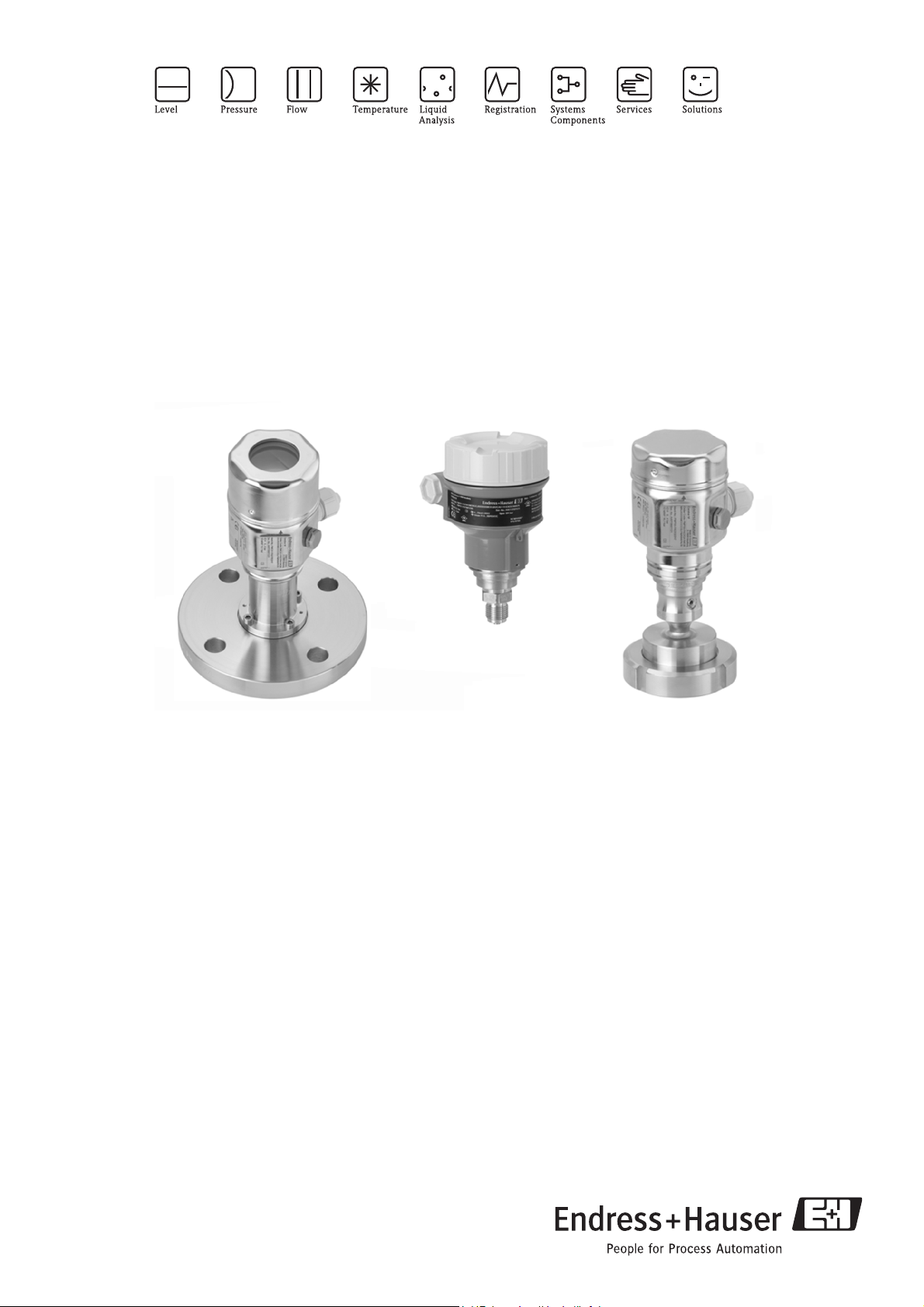
Cerabar M PMC51, PMP51, PMP55
Process pressure measurement
Pressure transmitter with ceramic and metal sensors;
Modular design and easy operation;
With analog or HART electronics
Application
The Cerabar M pressure transmitter is used for the
following measuring tasks:
• Absolute pressure and gauge pressure measurement in
gases, steams or liquids in all areas of process
engineering and process measurement technology
• Level, volume or mass measurements in liquids
• High process temperature
– without diaphragm seals up to 125°C (257°F)
– with diaphragm seals up to 400°C (752°F)
• High pressure up to 400 bar (6000 psi)
• International usage thanks to a wide range of approvals
Your benefits
• Very good reproducibility and long-term stability
• High reference accuracy: up to 0.15%,
as PLATINUM version: 0.075%
• Turn down up to 100:1
• End-to-end modularity for differential pressure,
hydrostatics and pressure (Deltabar M – Deltapilot M –
Cerabar M), e.g.
– replaceable display
– universal electronics
• Easy commissioning without the need for an operating
tool
• Menu-guided operation
• Output signals: 4 to 20 mA, 4 to 20 mA with HART
TI436P/00/EN/02.10
No. 71109889

Table of contents
Cerabar M PMC51, PMP51, PMP55
Function and system design. . . . . . . . . . . . . . . . . . . . . 4
Device selection . . . . . . . . . . . . . . . . . . . . . . . . . . . . . . . . . . . . . . 4
Measuring principle . . . . . . . . . . . . . . . . . . . . . . . . . . . . . . . . . . . 5
Level measurement (level, volume and mass) . . . . . . . . . . . . . . . . 6
Electrical differential pressure measurement with gauge pressure
sensors . . . . . . . . . . . . . . . . . . . . . . . . . . . . . . . . . . . . . . . . . . . . . 6
Communication protocol . . . . . . . . . . . . . . . . . . . . . . . . . . . . . . . 6
System integration (except analog electronics) . . . . . . . . . . . . . . . . 6
Input . . . . . . . . . . . . . . . . . . . . . . . . . . . . . . . . . . . . . . 7
Measured variable . . . . . . . . . . . . . . . . . . . . . . . . . . . . . . . . . . . . 7
Measuring range . . . . . . . . . . . . . . . . . . . . . . . . . . . . . . . . . . . . . . 7
Explanation of terms . . . . . . . . . . . . . . . . . . . . . . . . . . . . . . . . . . . 9
Output . . . . . . . . . . . . . . . . . . . . . . . . . . . . . . . . . . . . 10
Output signal . . . . . . . . . . . . . . . . . . . . . . . . . . . . . . . . . . . . . . . 10
Signal range . . . . . . . . . . . . . . . . . . . . . . . . . . . . . . . . . . . . . . . . 10
Signal on alarm . . . . . . . . . . . . . . . . . . . . . . . . . . . . . . . . . . . . . 10
Load - 4 to 20 mA analog and 4 to 20 mA HART . . . . . . . . . . . . 10
Resolution . . . . . . . . . . . . . . . . . . . . . . . . . . . . . . . . . . . . . . . . . 10
Dead time, Time constant (T63) . . . . . . . . . . . . . . . . . . . . . . . . . 10
Dynamic behavior: 4 to 20 mA (analog electronics) . . . . . . . . . . . 11
Dynamic behavior: current output (HART electronics) . . . . . . . . 11
Dynamic behavior: digital output (HART electronics) . . . . . . . . . 11
Damping . . . . . . . . . . . . . . . . . . . . . . . . . . . . . . . . . . . . . . . . . . 11
Operating conditions (installation) . . . . . . . . . . . . . . 19
General installation instructions . . . . . . . . . . . . . . . . . . . . . . . . . 19
Measuring arrangement for devices without diaphragm seal –
PMC51, PMP51 . . . . . . . . . . . . . . . . . . . . . . . . . . . . . . . . . . . . 19
Measuring arrangement for devices with diaphragm seal
– PMP55 . . . . . . . . . . . . . . . . . . . . . . . . . . . . . . . . . . . . . . . . . . 19
Wall and pipe mounting . . . . . . . . . . . . . . . . . . . . . . . . . . . . . . . 19
"Separate housing" version . . . . . . . . . . . . . . . . . . . . . . . . . . . . . 20
Oxygen applications . . . . . . . . . . . . . . . . . . . . . . . . . . . . . . . . . . 21
Silicone-free applications . . . . . . . . . . . . . . . . . . . . . . . . . . . . . . 21
Ultrapure gas applications . . . . . . . . . . . . . . . . . . . . . . . . . . . . . . 21
Applications with hydrogen . . . . . . . . . . . . . . . . . . . . . . . . . . . . 21
Operating conditions (environment) . . . . . . . . . . . . . 22
Ambient temperature range . . . . . . . . . . . . . . . . . . . . . . . . . . . . 22
Storage temperature range . . . . . . . . . . . . . . . . . . . . . . . . . . . . . 22
Degree of protection . . . . . . . . . . . . . . . . . . . . . . . . . . . . . . . . . 22
Climate class . . . . . . . . . . . . . . . . . . . . . . . . . . . . . . . . . . . . . . . 22
Vibration resistance . . . . . . . . . . . . . . . . . . . . . . . . . . . . . . . . . . 23
Electromagnetic compatibility . . . . . . . . . . . . . . . . . . . . . . . . . . 23
Overvoltage protection (optional) . . . . . . . . . . . . . . . . . . . . . . . . 23
Operating conditions (process) . . . . . . . . . . . . . . . . . 24
Process temperature limits . . . . . . . . . . . . . . . . . . . . . . . . . . . . . 24
Pressure specifications . . . . . . . . . . . . . . . . . . . . . . . . . . . . . . . . 25
Power supply . . . . . . . . . . . . . . . . . . . . . . . . . . . . . . . 12
Electrical connection . . . . . . . . . . . . . . . . . . . . . . . . . . . . . . . . . 12
Supply voltage . . . . . . . . . . . . . . . . . . . . . . . . . . . . . . . . . . . . . . 14
Cable entry . . . . . . . . . . . . . . . . . . . . . . . . . . . . . . . . . . . . . . . . 14
Cable specification . . . . . . . . . . . . . . . . . . . . . . . . . . . . . . . . . . . 14
Residual ripple . . . . . . . . . . . . . . . . . . . . . . . . . . . . . . . . . . . . . . 14
Influence of power supply . . . . . . . . . . . . . . . . . . . . . . . . . . . . . . 14
Performance characteristics – general . . . . . . . . . . . . 15
Reference operating conditions . . . . . . . . . . . . . . . . . . . . . . . . . . 15
Uncertainty of measurement for small absolute pressure ranges . . 15
Long-term stability . . . . . . . . . . . . . . . . . . . . . . . . . . . . . . . . . . . 15
Influence of orientation . . . . . . . . . . . . . . . . . . . . . . . . . . . . . . . 15
Warm-up period . . . . . . . . . . . . . . . . . . . . . . . . . . . . . . . . . . . . . 15
Performance characteristics – ceramic process isolating
diaphragm . . . . . . . . . . . . . . . . . . . . . . . . . . . . . . . . . 16
Reference accuracy – PMC51 . . . . . . . . . . . . . . . . . . . . . . . . . . . 16
Total performance – PMC51 . . . . . . . . . . . . . . . . . . . . . . . . . . . 16
Total error - PMC51 . . . . . . . . . . . . . . . . . . . . . . . . . . . . . . . . . . 16
Thermal change in the zero output and the output span – PMC51 .
16
Performance characteristics – metal process isolating
diaphragm . . . . . . . . . . . . . . . . . . . . . . . . . . . . . . . . . 17
Reference accuracy – PMP51, PMP55 . . . . . . . . . . . . . . . . . . . . 17
Total performance – PMP51 . . . . . . . . . . . . . . . . . . . . . . . . . . . . 17
Total error - PMP51 . . . . . . . . . . . . . . . . . . . . . . . . . . . . . . . . . . 17
Thermal change in the zero output and the output span – PMP51 and
PMP55 . . . . . . . . . . . . . . . . . . . . . . . . . . . . . . . . . . . . . . . . . . . 18
Mechanical construction . . . . . . . . . . . . . . . . . . . . . . 26
F31 aluminum housing dimensions . . . . . . . . . . . . . . . . . . . . . . 26
F15 stainless steel housing dimensions (hygienic) . . . . . . . . . . . . 26
Process connections PMC51 (with ceramic process isolating
diaphragm) . . . . . . . . . . . . . . . . . . . . . . . . . . . . . . . . . . . . . . . . 26
Process connections PMP51 (with metal process isolating diaphragm)
32
PMP55 basic device . . . . . . . . . . . . . . . . . . . . . . . . . . . . . . . . . . 37
Process connections PMP55 (with diaphragm seal) . . . . . . . . . . . 38
Wall and pipe mounting with mounting bracket . . . . . . . . . . . . 52
Weight . . . . . . . . . . . . . . . . . . . . . . . . . . . . . . . . . . . . . . . . . . . 52
Material . . . . . . . . . . . . . . . . . . . . . . . . . . . . . . . . . . . . . . . . . . . 52
Human interface . . . . . . . . . . . . . . . . . . . . . . . . . . . . 54
Operating elements . . . . . . . . . . . . . . . . . . . . . . . . . . . . . . . . . . 54
Onsite operation . . . . . . . . . . . . . . . . . . . . . . . . . . . . . . . . . . . . 56
Remote operation . . . . . . . . . . . . . . . . . . . . . . . . . . . . . . . . . . . 57
Planning instructions for diaphragm seal systems . . . 58
Applications . . . . . . . . . . . . . . . . . . . . . . . . . . . . . . . . . . . . . . . . 58
Function and design . . . . . . . . . . . . . . . . . . . . . . . . . . . . . . . . . . 58
Diaphragm seal filling oils . . . . . . . . . . . . . . . . . . . . . . . . . . . . . . 59
Operating temperature range . . . . . . . . . . . . . . . . . . . . . . . . . . . 59
Installation instructions . . . . . . . . . . . . . . . . . . . . . . . . . . . . . . . 60
Certificates and approvals . . . . . . . . . . . . . . . . . . . . . 62
CE mark . . . . . . . . . . . . . . . . . . . . . . . . . . . . . . . . . . . . . . . . . . 62
Ex approvals . . . . . . . . . . . . . . . . . . . . . . . . . . . . . . . . . . . . . . . 62
Suitability for hygienic processes . . . . . . . . . . . . . . . . . . . . . . . . . 62
Pressure Equipment Directive (PED) . . . . . . . . . . . . . . . . . . . . . 62
Standards and guidelines . . . . . . . . . . . . . . . . . . . . . . . . . . . . . . 62
2 Endress+Hauser

Ordering information . . . . . . . . . . . . . . . . . . . . . . . . 63
PMC51 . . . . . . . . . . . . . . . . . . . . . . . . . . . . . . . . . . . . . . . . . . . 63
PMC51 (continued) . . . . . . . . . . . . . . . . . . . . . . . . . . . . . . . . . . 64
PMC51 (continued) . . . . . . . . . . . . . . . . . . . . . . . . . . . . . . . . . . 65
PMC51 (continued) . . . . . . . . . . . . . . . . . . . . . . . . . . . . . . . . . . 66
PMP51 . . . . . . . . . . . . . . . . . . . . . . . . . . . . . . . . . . . . . . . . . . . 67
PMP51 (continued) . . . . . . . . . . . . . . . . . . . . . . . . . . . . . . . . . . 68
PMP51 (continued) . . . . . . . . . . . . . . . . . . . . . . . . . . . . . . . . . . 69
PMP51 (continued) . . . . . . . . . . . . . . . . . . . . . . . . . . . . . . . . . . 70
PMP55 . . . . . . . . . . . . . . . . . . . . . . . . . . . . . . . . . . . . . . . . . . . 71
PMP55 (continued) . . . . . . . . . . . . . . . . . . . . . . . . . . . . . . . . . . 72
PMP55 (continued) . . . . . . . . . . . . . . . . . . . . . . . . . . . . . . . . . . 73
PMP55 (continued) . . . . . . . . . . . . . . . . . . . . . . . . . . . . . . . . . . 74
PMP55 (continued) . . . . . . . . . . . . . . . . . . . . . . . . . . . . . . . . . . 75
PMP55 (continued) . . . . . . . . . . . . . . . . . . . . . . . . . . . . . . . . . . 76
Documentation . . . . . . . . . . . . . . . . . . . . . . . . . . . . . 77
Technical Information . . . . . . . . . . . . . . . . . . . . . . . . . . . . . . . . 77
Operating Instructions . . . . . . . . . . . . . . . . . . . . . . . . . . . . . . . . 77
Brief Operating Instructions . . . . . . . . . . . . . . . . . . . . . . . . . . . . 77
Safety Instructions . . . . . . . . . . . . . . . . . . . . . . . . . . . . . . . . . . . 77
Installation/Control Drawings . . . . . . . . . . . . . . . . . . . . . . . . . . 78
Cerabar M PMC51, PMP51, PMP55
Accessories . . . . . . . . . . . . . . . . . . . . . . . . . . . . . . . . 79
Shutoff valve . . . . . . . . . . . . . . . . . . . . . . . . . . . . . . . . . . . . . . . 79
Siphon . . . . . . . . . . . . . . . . . . . . . . . . . . . . . . . . . . . . . . . . . . . . 79
Welding necks and Weld-in tool flanges . . . . . . . . . . . . . . . . . . . 80
Mounting bracket for wall and pipe mounting . . . . . . . . . . . . . . 80
M12 connector . . . . . . . . . . . . . . . . . . . . . . . . . . . . . . . . . . . . . 80
Configuration data sheet (HART electronics) . . . . . . 81
Level . . . . . . . . . . . . . . . . . . . . . . . . . . . . . . . . . . . . . . . . . . . . . 81
Pressure . . . . . . . . . . . . . . . . . . . . . . . . . . . . . . . . . . . . . . . . . . . 82
Configuration data sheet (analog electronics) . . . . . . 83
Pressure . . . . . . . . . . . . . . . . . . . . . . . . . . . . . . . . . . . . . . . . . . . 83
3 Endress+Hauser
Device selection
Cerabar M PMC51, PMP51, PMP55
Function and system design
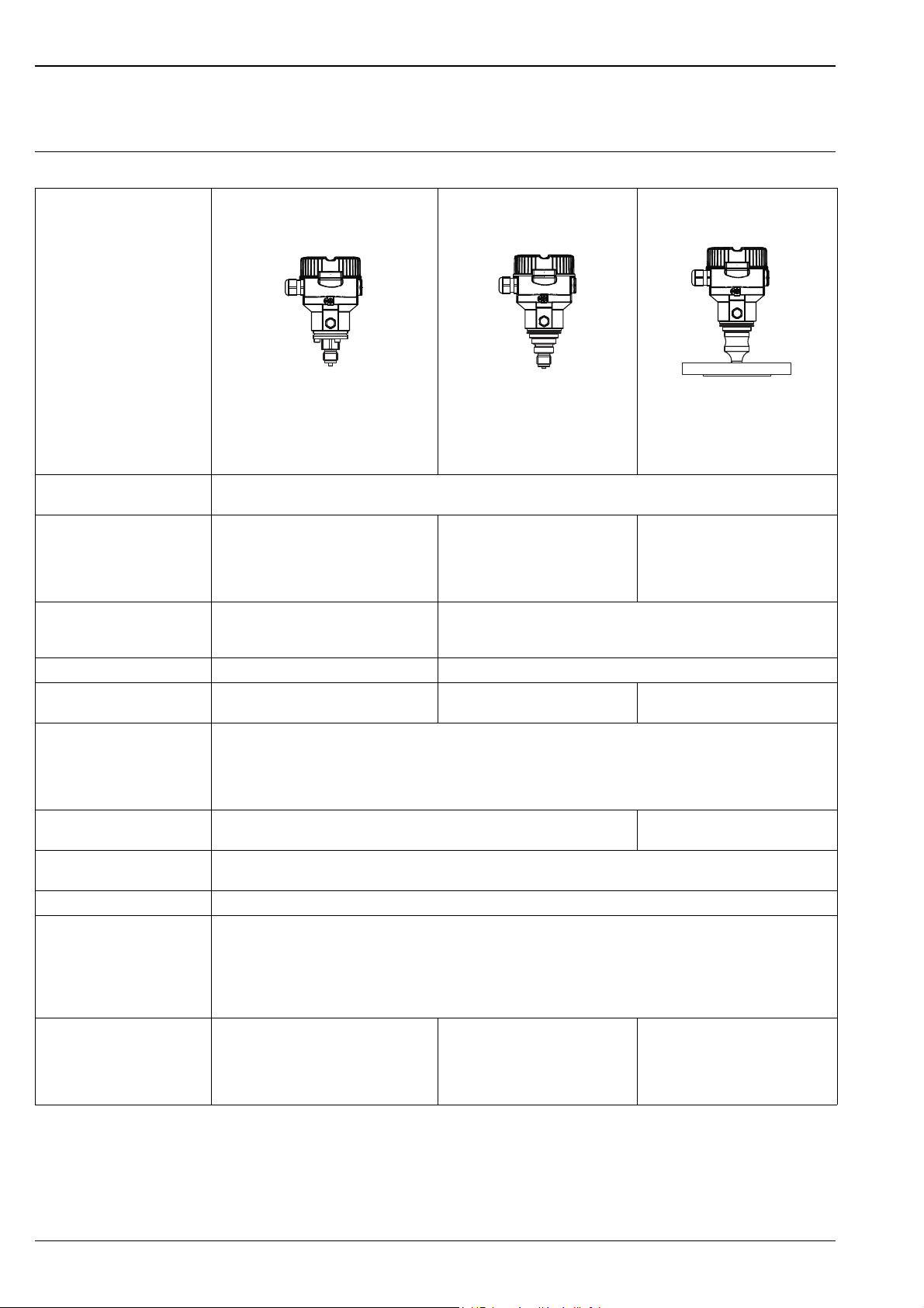
Cerabar M –
PMC51
PMP51
PMP55
Product family
P01-PMC51xxx-16-xx-xx-xx-000
With capacitive measuring cell and
ceramic process isolating diaphragm
(Ceraphire
®
)
With piezoresistive measuring cell
and metal welded process isolating
diaphragm
P01-PMP51xxx-16-xx-xx-xx-000
P01-PMP55xxx-16-xx-xx-xx-000
With diaphragm seal
Field of application – Gauge pressure and absolute pressure
– Level
Process connections – Thread
– EN flanges DN 25 – DN 80
– ANSI flanges 1" – 4"
– JIS flanges 50 A – 100 A
–Thread
– EN flanges DN 25 – DN 80
–ANSI flanges 1" – 4"
– JIS flanges 25 A – 100 A
– Wide range of diaphragm seals
– Prepared for diaphragm seal mount
Measuring ranges From –100/0 to 100 mbar (–1.5/0 to
1.5 psi)
From –400/0 to 400 mbar (–6/0 to 6 psi)
to –1/0 to 400 bar (–15/0 to 6000 psi)
to –1/0 to 40 bar (–15/0 to 600 psi)
1
OPL
Max. 60 bar (900 psi) Max. 600 bar (9000 psi)
Process temperature range –20 to +100 °C (–4 to +212°F) –40 to +125°C (–40 to +257°F) –70 to 400 °C (–94 to +752 °F)
depending on the filling oil
Ambient temperature range • Without LCD display: -40 to +85°C (–40 to +185 °F)
• With LCD display: –20 to +70°C (–4 to +158°F) (extended temperature application range (-40 to 85°C (-40 to 185°F)) with
restrictions in optical properties such as display speed and contrast)
• Separate housing: –20 to +60°C (–4 to +140°F)
• Diaphragm seal systems depending on the version
Reference accuracy – Up to 0.15% of the set span
Up to 0.15% of the set span
– PLATINUM version: up to 0.075% of the set span
Supply voltage – 11.5 to 45 V DC (versions with plug-in connection 35 V DC)
– For intrinsically safe device versions: 11.5 to 30 V DC
Output 4 to 20 mA, 4 to 20 mA with superimposed HART protocol
Options – PMP51, PMP55: NACE-compliant materials
– PMC51, PMP51, PMP55: inspection certificate 2.2 or 3.1 or other certificates
– Specific firmware versions
– Initial device settings
– Separate housing
– Broad range of accessories
Specialties – Metal-free measurement with PVDF
connection
– Special cleaning of the transmitter to
remove paint-wetting substances, for use
in paint shops
– Process connections with minimum
oil volume
– Gas-tight, elastomer-free
– Wide range of diaphragm seals
– For extreme medium temperatures
– Process connections with minimum
oil volume
– Completely welded versions
1) OPL = over pressure limit; depends on the lowest-rated element, with regard to pressure, of the selected components
4 Endress+Hauser
Cerabar M PMC51, PMP51, PMP55
p
➃
➂➀➁
➂
➀
➁
p
➃
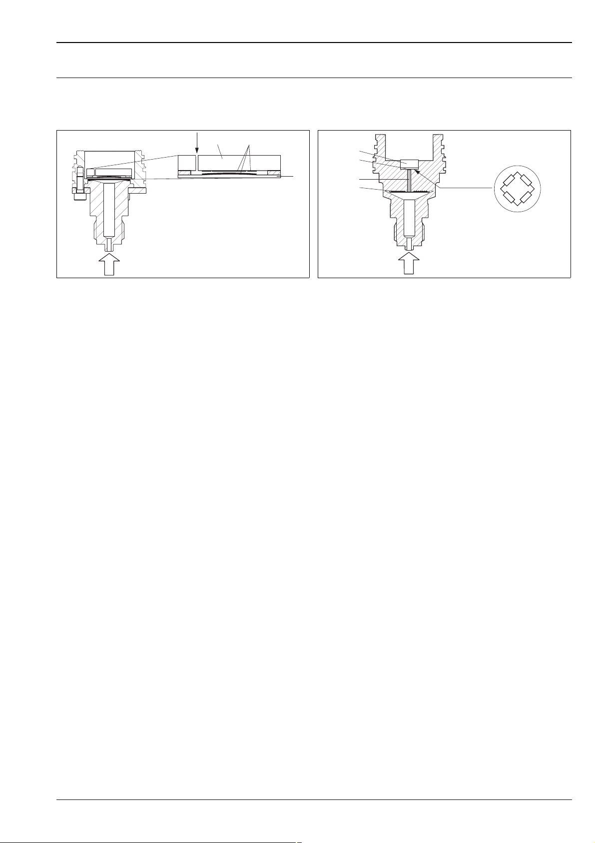
Measuring principle
Ceramic process isolating diaphragm used in PMC51 (Ceraphire®) Metal process isolating diaphragm used in PMP51 and PMP55
Ceramic sensor
1 Air pressure (gauge pressure sensors)
2 Ceramic substrate
3 Electrodes
4 Ceramic process isolating diaphragm
Ceramic process isolating diaphragm used in PMC51 (Ceraphire
The ceramic sensor is a dry sensor, i.e. the process pressure acts directly on the robust ceramic process isolating
diaphragm and deflects it. A pressure-dependent change in capacitance is measured at the electrodes of the
ceramic substrate and the process isolating diaphragm. The measuring range is determined by the thickness of
the ceramic process isolating diaphragm.
Advantages:
• Guaranteed overload resistance up to 40 times the nominal pressure
• Thanks to ultrapure 99.9% ceramic (Ceraphire
• Can be used in absolute vacuum
• Outstanding surface finish, R
Metal process isolating diaphragm used in PMP51 and PMP55
PMP51
The operating pressure deflects the process isolating diaphragm and a fill fluid transfers the pressure to a
resistance bridge (semiconductor technology). The pressure-dependent change in the bridge output voltage is
measured and evaluated.
Advantages:
• Can be used for process pressure up to 400 bar (6000 psi)
• High long-term stability
• Guaranteed overload resistance up to 4 times the nominal pressure
• Significantly less thermal effect compared to diaphragm seal systems
P01-PMC71xxx-03-xx-xx-xx-000
Metal sensor
1 Silicon measuring element, substrate
2 Wheatstone bridge
3 Channel with fill fluid
4 Metal process isolating diaphragm
®
, see also "www.endress.com/ceraphire")
– extremely high chemical stability, comparable with Alloy C
– less relaxation
– high mechanical stability
0.3 m (11.8 in)
a
P01-PMP7xxxx-03-xx-xx-xx-000
®
)
PMP55
The operating pressure acts on the process isolating diaphragm of the diaphragm seal and is transferred to the
process isolating diaphragm of the sensor by a diaphragm seal fill fluid. The process isolating diaphragm is
deflected and a fill fluid transfers the pressure to a resistance bridge. The pressure-dependent change in the
bridge output voltage is measured and evaluated.
Advantages:
• Depending on the version, can be used for process pressure up to 400 bar (6000 psi) and simultaneous
extreme process temperatures
• High long-term stability
• Guaranteed overload resistance up to 4 times the nominal pressure
Endress+Hauser 5
Cerabar M PMC51, PMP51, PMP55
h =
p
r g
h
Fieldgate
FXA520
FXN 520
FXN 520
Multidrop-Connector
FXN520
Cerabar M
➀
➁
➀
➁
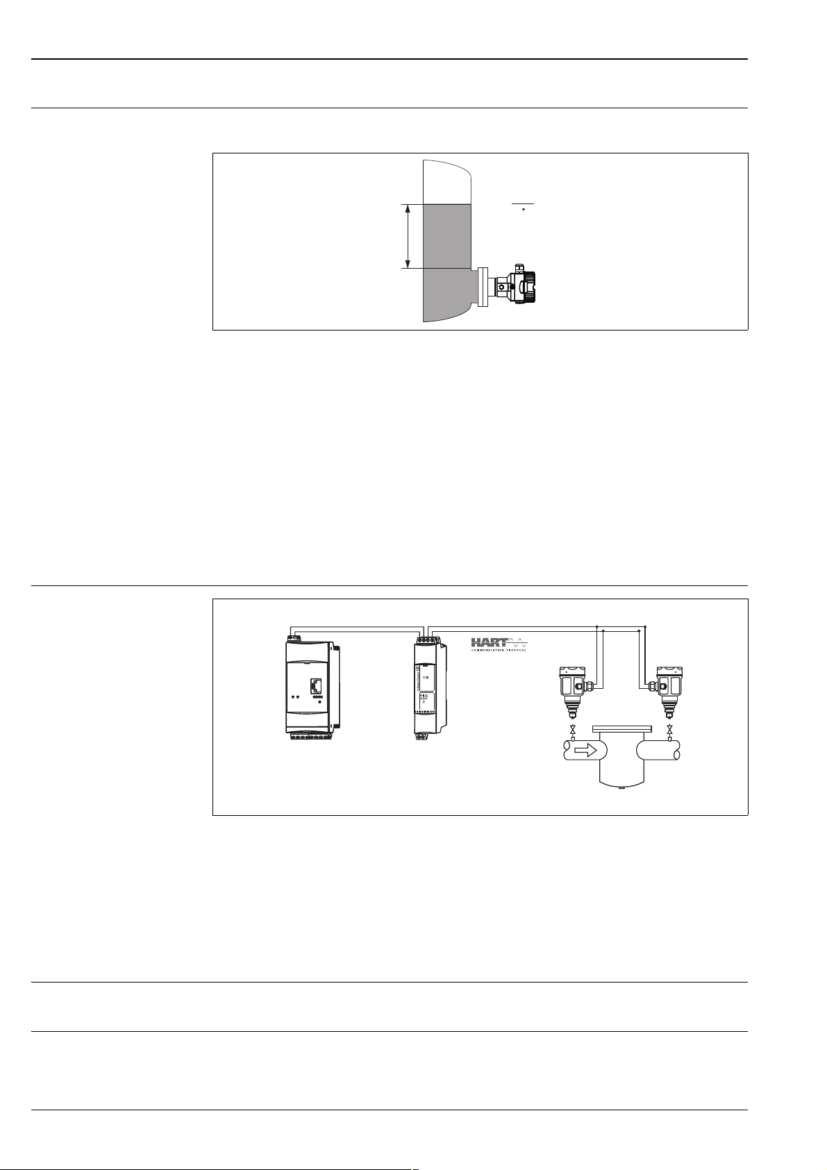
Level measurement (level, volume and mass)
Function and design
P01-PMx5xxxx-15-xx-xx-xx-000
Level measurement
h Height (level)
pPressure
Density of the medium
g Gravitation constant
Your benefits
• Choice of different level measuring modes in the device software
• Volume and mass measurements in any tank shapes by means of a freely programmable characteristic curve
• Choice of diverse level units
• Has a wide range of uses, even in the following cases:
– in the event of foam formation
– in tanks with agitators or screen fittings
– in the event of liquid gases
Electrical differential pressure measurement with gauge pressure sensors
1 Shut-off valves
2 e.g. filter
In the example given, two Cerabar M devices (each with a gauge pressure sensor) are interconnected. The
pressure difference can thus be measured using two independent Cerabar M devices.
Caution!
"
If using intrinsically safe devices, strict compliance with the rules for interconnecting intrinsically safe circuits
as stipulated in IEC60079-14 (proof of intrinsic safety) is mandatory.
Communication protocol • 4 to 20 mA without communication protocol (analog electronics)
• 4 to 20 mA with HART communication protocol
P01-PMX51xxx-14-xx-xx-xx-001
System integration (except analog electronics)
6 Endress+Hauser
The device can be fitted with a tag name and a preset bus address, see ä 63 ff "Ordering information"
feature 895 "Identification:" version "Z1" and "Z2".

Cerabar M PMC51, PMP51, PMP55
Input
Measured variable • Analog electronics: Absolute pressure and gauge pressure
• HART electronics: Absolute pressure and gauge pressure, from which level (level, volume or mass) is derived
Measuring range PMC51 – with ceramic process isolating diaphragm (Ceraphire
®
) for gauge pressure
Nominal value Range limit Smallest
calibratable span
(preset at the
factory)
MWP
OPL
Vacuum
resistance
Version in
the order
code
lower (LRL) upper (URL)
[bar (psi)] [bar (psi)] [bar (psi)] [bar (psi)] [bar (psi)] [bar
abs
(psi
abs
)]
100 mbar (1.5 psi) –0.1 (–1.5) +0.1 (+1.5) 0.01 (0.15) 2.7 (40.5) 4 (60) 0.7 (10.5) 1C
250 mbar (4 psi) –0.25 (–4) +0.25 (+4) 0.01 (0.15) 3.3 (49.5) 5 (75) 0.5 (7.5) 1E
400 mbar (6 psi) –0.4 (–6) +0.4 (+6) 0.02 (0.3) 5.3 (79.5) 8 (120) 0 1F
1 bar (15 psi) –1 (–15) +1 (+15) 0.05 (1) 6.7 (100.5) 10 (150) 0 1H
2 bar (30 psi) –1 (–15) +2 (+30) 0.1 (1.5) 12 (180) 18 (270) 0 1K
4 bar (60 psi) –1 (–15) +4 (+60) 0.2 (3) 16.7 (250.5) 25 (375) 0 1M
10 bar (150 psi) –1 (–15) +10 (+150) 0.5 (7.5) 26.7 (400.5) 40 (600) 0 1P
40 bar (600 psi) –1 (–15) +40 (+600) 2 (30) 40 (600) 60 (900) 0 1S
®
PMC51 – with ceramic process isolating diaphragm (Ceraphire
Nominal value Range limit Smallest span
(factory
calibration)
1
MWP
2
OPL
) for absolute pressure
3
Vacuum
resistance
Version in
the order
code
lower (LRL) upper (URL)
[bar
(psi
abs
)] [bar
abs
abs
(psi
)] [bar (psi)] [bar
abs
abs
(psi
)] [bar
abs
abs
(psi
)] [bar
abs
abs
(psi
abs
)]
100 mbar (15 psi) 0 +0.1 (+1.5) 0.01 (0.15) 2.7 (40.5) 4 (60) 0 2C
250 mbar (4 psi) 0 +0.25 (+4) 0.01 (0.15) 3.3 (49.5) 5 (75) 0 2E
400 mbar (6 psi) 0 +0.4 (+6) 0.02 (0.3) 5.3 (79.5) 8 (120) 0 2F
1 bar (15 psi) 0 +1 (+15) 0.05 (1) 6.7 (100.5) 10 (150) 0 2H
2 bar (30 psi) 0 +2 (+30) 0.1 (1.5) 12 (180) 18 (270) 0 2K
4 bar (60 psi) 0 +4 (+60) 0.2 (3) 16.7 (250.5) 25 (375) 0 2M
10 bar (150 psi) 0 +10 (+150) 0.5 (7.5) 26.7 (400.5) 40 (600) 0 2P
40 bar (600 psi) 0 +40 (+600) 2 (30) 40 (600) 60 (900) 0 2S
4
1) Recommended turn down: Max 100:1.
Factory calibration turn down: Max 20:1, higher on request or configurable in the device.
2) The MWP (maximum working pressure) for the measuring device depends on the lowest-rated element, with regard to pressure, of the selected components,
i.e. the process connection ( ä 26 ff) has to be taken into consideration in addition to the measuring cell ( see Table above). Pay attention to the
pressure-temperature dependence also. For the appropriate standards and other information, see ä 25, "Pressure specifications" section.
3) OPL: over pressure limit depends on the lowest-rated element, with regard to pressure, of the selected components
4) Version in the order code see also ä 63 ff, feature 70 "Sensor range"
Endress+Hauser 7

Cerabar M PMC51, PMP51, PMP55
PMP51 and PMP55 – metal process isolating diaphragm for gauge pressure
Nominal value Range limit Smallest
calibratable span
(preset at the
factory)
MWP
OPL
Vacuum
resistance
Version in the
order code
Silicone oil/
Inert oil
lower (LRL) upper (URL)
[bar (psi)] [bar (psi)] [bar (psi)] [bar (psi)] [bar (psi)] [bar
400 mbar (6 psi) –0.4 (–6) +0.4 (+6) 0.02 (0.3) 4 (60) 6 (90)
abs
(psi
abs
)]
1F
1 bar (15 psi) –1 (–15) +1 (+15) 0.05 (1) 6.7 (100) 10 (150) 1H
2 bar (30 psi) –1 (–15) +2 (+30) 0.1 (1.5) 13.3 (200) 20 (300) 1K
4 bar (60 psi) –1 (–15) +4 (+60) 0.2 (3) 18.7 (280.5) 28 (420) 1M
10 bar (150 psi) –1 (–15) +10 (+150) 0.5 (7.5) 26.7 (400.5) 40 (600) 1P
0.01/0.04
(0.15/0.6)
40 bar (600 psi) –1 (–15) +40 (+600) 2 (30) 100 (1500) 160 (2400) 1S
100 bar (1500 psi) –1 (–15) +100 (+1500) 5 (75) 100 (1500) 400 (6000) 1U
400 bar (6000 psi) –1 (–15) +400 (+6000) 20 (300) 400 (6000) 600 (9000) 1W
PMP51 and PMP55 – metal process isolating diaphragm for absolute pressure
Nominal value Range limit Smallest
calibratable span
(preset at the
factory)
1
MWP 2 OPL 3Vacuum
resistance
Silicone oil/
Inert oil
Version in the
4
order code
5
lower (LRL) upper (URL)
[bar
(psi
abs
)] [bar
abs
400 mbar (6 psi) 0 +0.4 (+6) 0.02 (0.3) 4 (60) 6 (90)
abs
(psi
)] [bar (psi)] [bar
abs
abs
(psi
)] [bar
abs
abs
(psi
)] [bar
abs
abs
(psi
abs
)]
2F
1 bar (15 psi) 0 +1 (+15) 0.05 (1) 6.7 (100) 10 (150) 2H
2 bar (30 psi) 0 +2 (+30) 0.1 (1.5) 13.3 (200) 20 (300) 2K
4 bar (60 psi) 0 +4 (+60) 0.2 (3) 18.7 (280.5) 28 (420) 2M
10 bar (150 psi) 0 +10 (+150) 0.5 (7.5) 26.7 (400.5) 40 (600) 2P
0.01/0.04
(0.15/0.6)
40 bar (600 psi) 0 +40 (+600) 2 (30) 100 (1500) 160 (2400) 2S
100 bar (1500 psi) 0 +100 (+1500) 5 (75) 100 (1500) 400 (6000) 2U
400 bar (6000 psi) 0 +400 (+6000) 20 (300) 400 (6000) 600 (9000) 2W
1) Recommended turn down: Max 100:1.
Factory calibration turn down: Max 20:1, higher on request or configurable in the device.
2) The MWP (maximum working pressure) for the measuring device depends on the lowest-rated element, with regard to pressure, of the selected components,
i.e. the process connection ( ä 26 ff) has to be taken into consideration in addition to the measuring cell (see Table above). Pay attention to the
pressure-temperature dependence also. For the appropriate standards and other information, see ä 25, "Pressure specifications" section.
3) OPL: over pressure limit (= sensor overload limit)
4) The vacuum resistance applies to the measuring cell at reference conditions. The pressure and temperature application limits of the selected filling oil must
also be observed for the PMP55. ä 59, "Diaphragm seal filling oils" section.
5) Version in the order code ä 63 ff, feature 70 "Sensor range"
8 Endress+Hauser
Cerabar M PMC51, PMP51, PMP55
0 bar
+1 bar
URLURV
➂
LRL = LRV
0.5 bar
➃
➁➀
=
➄
=
–1 bar
+1 bar
LRV
URLURV
➂
0
LRL
0.5 bar
➁➀
=
➃
➄
–1 bar
+1 bar
LRV
URLURV
➂
0
LRL
–0.6 bar
➁➀
=
➃
➄
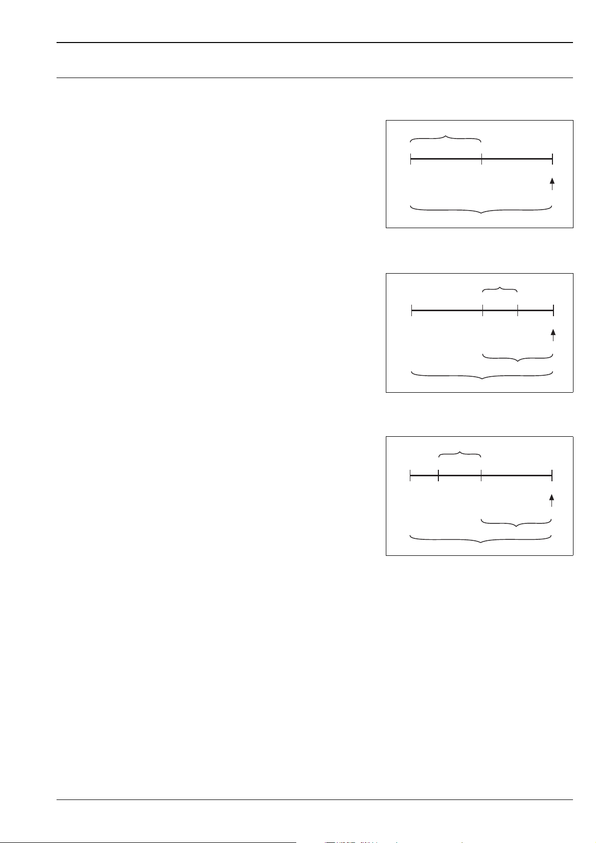
Explanation of terms
Explanation of terms: turn down (TD),
set span and span based on zero point
Case 1:
• Lower range value (LRV) Upper range value
(URV)
Example:
• Lower range value (LRV) = 0 bar
• Upper range value (URV) = 0.5 bar (7.5 psi)
• Nominal value (URL) = 1 bar (15 psi)
Turn down:
•TD = URL /URV2:1
Set span:
• URV – LRV = 0.5 bar (7.5 psi)
This span is based on the zero point.
Case 2:
• Lower range value (LRV) Upper range value
(URV)
Example:
• Lower range value (LRV) = 0 bar
• Upper range value (URV) = 0.5 bar (7.5 psi)
• Nominal value (URL) = 1 bar (15 psi)
Turn down:
•TD = URL /URV= 2:1
Set span:
• URV – LRV = 0.5 bar (7.5 psi)
This span is based on the zero point.
P01-PMx7xxxx-05-xx-xx-xx-012
Example: 1 bar (15 psi) measuring cell
P01-PMx7xxxx-05-xx-xx-xx-007.
Example: 1 bar (15 psi) measuring cell
Case 3:
• Lower range value (LRV) Upper range value
(URV)
Example:
• Lower range value (LRV) = –0.6 bar (–9 psi)
• Upper range value (URV) = 0 bar
• Nominal value (URL) = 1 bar (15 psi)
Turn down:
•TD = URL /LRV = 1.67:1
Set span:
• URV – LRV = 0.6 bar (–9 psi)
This span is based on the zero point.
P01-PMx7xxxx-05-xx-xx-xx-008
Example: 1 bar (15 psi) measuring cell
1 Set span
2 Span based on zero point
3 Nominal value i upper range limit (URL)
4 Nominal measuring range
5 Sensor measuring range
LRL Lower range limit
URL Upper range limit
LRV Lower range value
URV Upper range value
Endress+Hauser 9
Output
U – 11.5 V
R
L
max
0.023 A
£
30
20
11.5
U
[V]
40 45
1239
1456
804
369
[]W
R
L
max
➀
➁
I
63 %
100 %
t
t1t
2
90 %
t
3
Output signal • 4 to 20 mA analog, 2-wire
• 4 to 20 mA with superimposed digital communication protocol HART 6.0, 2-wire
Signal range 4 to 20 mA analog, 4 to 20 mA HART: 3.8 to 20.5 mA
Signal on alarm As per NAMUR NE 43
• 4 to 20 mA Analog:
– Signal overshoot: > 20.5 mA
– Signal undershoot: < 3.8 mA
– Min Alarm (3.6 mA)
• 4 to 20 mA HART
Options:
– Max. alarm: can be set from 21 to 23 mA (factory setting: 22 mA)
– Hold measured value: last measured value is held
– Min. alarm: 3.6 mA
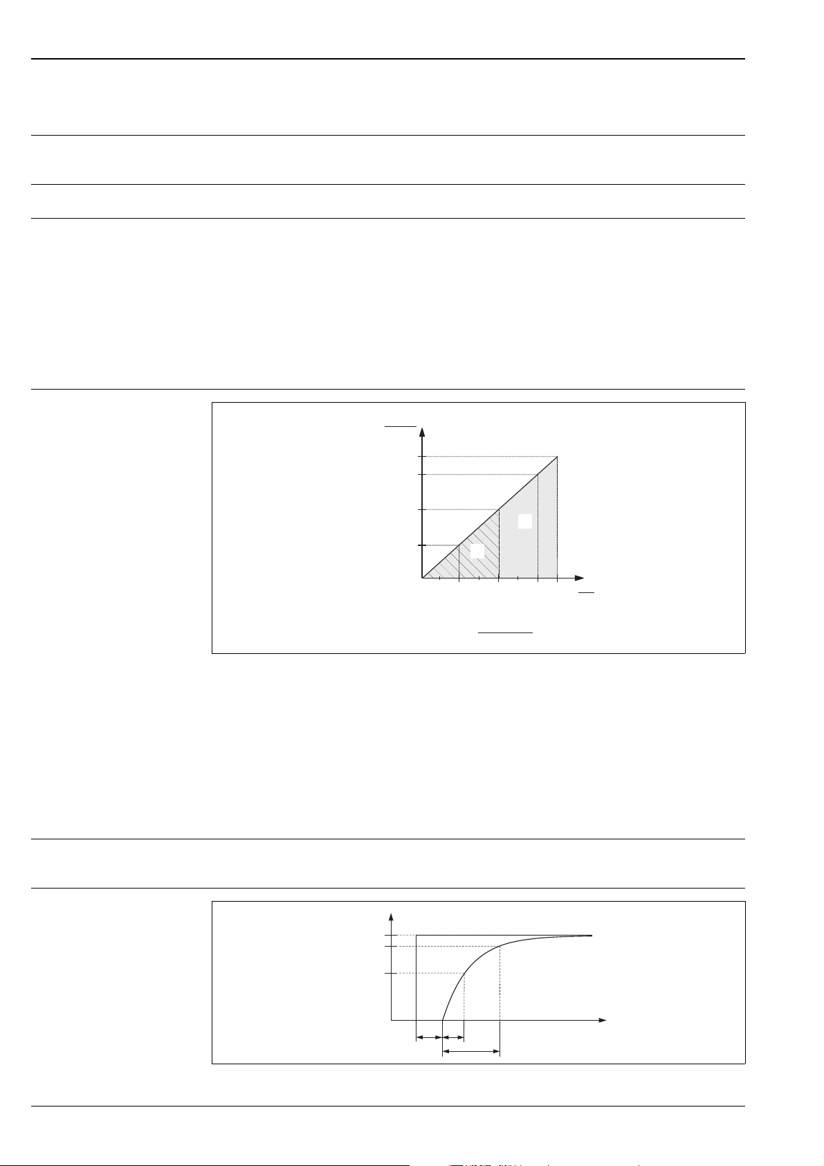
Load - 4 to 20 mA analog and
4 to 20 mA HART
Cerabar M PMC51, PMP51, PMP55
P01-xxxxxxxx-05-xx-xx-xx-002
Load diagram
1 Power supply 11.5 to 30 V DC for intrinsically safe device versions
2 Power supply 11.5 to 45 V DC (versions with plug-in connector 35 V DC) for other types of protection and for
uncertified device versions
R
Maximum load resistance
Lmax
U Supply voltage
Note!
When operating via a handheld terminal or via a PC with an operating program, a minimum communication
resistance of 250 must be taken into account.
Resolution • Current output: 1 A
• Display HART: can be set (factory setting: presentation of the maximum accuracy of the transmitter)
Dead time,
Time constant (T63)
10 Endress+Hauser
Presentation of the dead time and the time constant
P01-xxxxxxxx-05-xx-xx-xx-036

Cerabar M PMC51, PMP51, PMP55
Dynamic behavior: 4 to 20 mA (analog electronics)
Dynamic behavior:
current output (HART
electronics)
Dynamic behavior: digital output (HART electronics)
Dead time, time constant (T63)
Type Dead time t
PMC51 60 ms 40 ms 50 ms
PMP51 40 ms 40 ms 50 ms
PMP55 PMP51 + influence of the diaphragm seal
Type Dead time t
PMC51 90 ms 120 ms
PMP51 60 ms 70 ms
PMP55 PMP51 + influence of the diaphragm seal
1
1
Time constant (T63), t
Time constant (T63), t
2
2
Time constant (T90), t
Dead time, time constant (T63)
A typical configuration for the PLC of 2 to 3 values per second results in the following
total dead time:
Type Dead time t
PMC51 340 ms 120 ms
PMP51 310 ms 70 ms
PMP55 PMP51 + influence of the diaphragm seal
1
Time constant (T63), t
2
3
Reading cycle
HART commands: 2 to 3 per second on average.
The Cerabar M commands the BURST MODE function for cyclic value transmission via the HART
communication protocol.
Response time
250 ms
Cycle time (update time)
On average 310 to 520 ms.
Damping A damping affects all outputs (output signal, display).
• Analog electronics: via DIP switch on the electronic insert,
switch position "on" = 2s; switch position "off" = 0s
• HART: via DIP switch on the electronic insert, switch position "on" = value set in the software (factory
setting: 2 s) and "off". Via local display, handheld terminal or PC with operating program, continuous from
0 to 999 s
Endress+Hauser 11
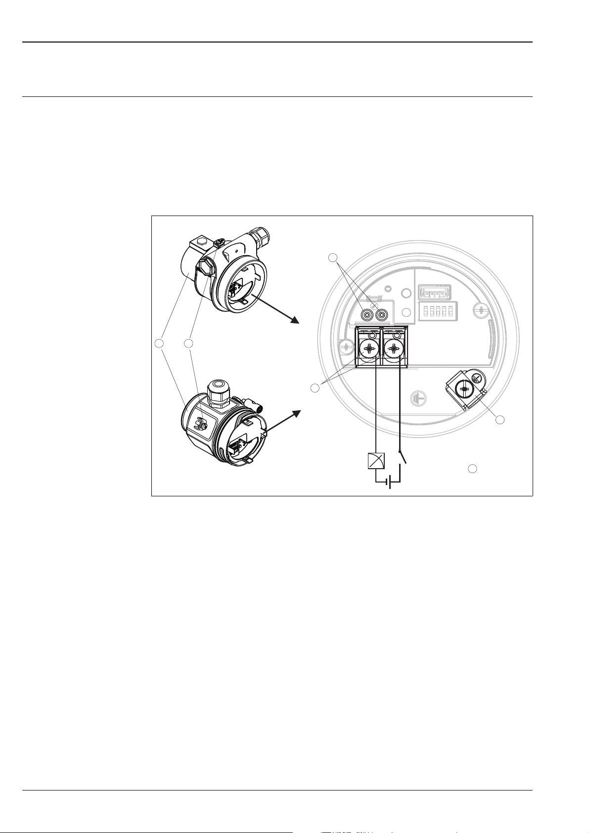
Power supply
4…20 mA
11.5 V DC
- +
6
1 2
3
4
5
Electrical connection Note!
• When using the measuring device in hazardous areas, installation must comply with the corresponding
national standards and regulations and the Safety Instructions or Installation or Control Drawings.
ä 77 ff, "Safety Instructions" and "Installation/Control Drawings" sections.
• HART: Overvoltage protection HAW569Z for the non-hazardous area and for ATEX II 1/2 G Exi can be
ordered as an option (see "Ordering information" section).
• Protective circuits against reverse polarity, HF influences and overvoltage peaks are installed.
4 to 20 mA analog, 4 to 20 mA HART
Cerabar M PMC51, PMP51, PMP55
P01-xMx5xxxx-04-xx-xx-xx-004
Electrical connection
1 Housing
2 External ground terminal
3 Internal ground terminal
4 Power supply terminals
5 Test terminals, see "Taking 4 to 20 mA test signal" section
6 Minimum supply voltage = 11.5 V DC
Taking 4 to 20 mA test signal
A 4 to 20 mA test signal may be measured via the test terminals without interrupting the measurement.
12 Endress+Hauser
Cerabar M PMC51, PMP51, PMP55
–
+
+–
+
–
Han7D
–
+
+–
–
+
1
5
4
6
7
8
2
3
M12
–
+
+–
–
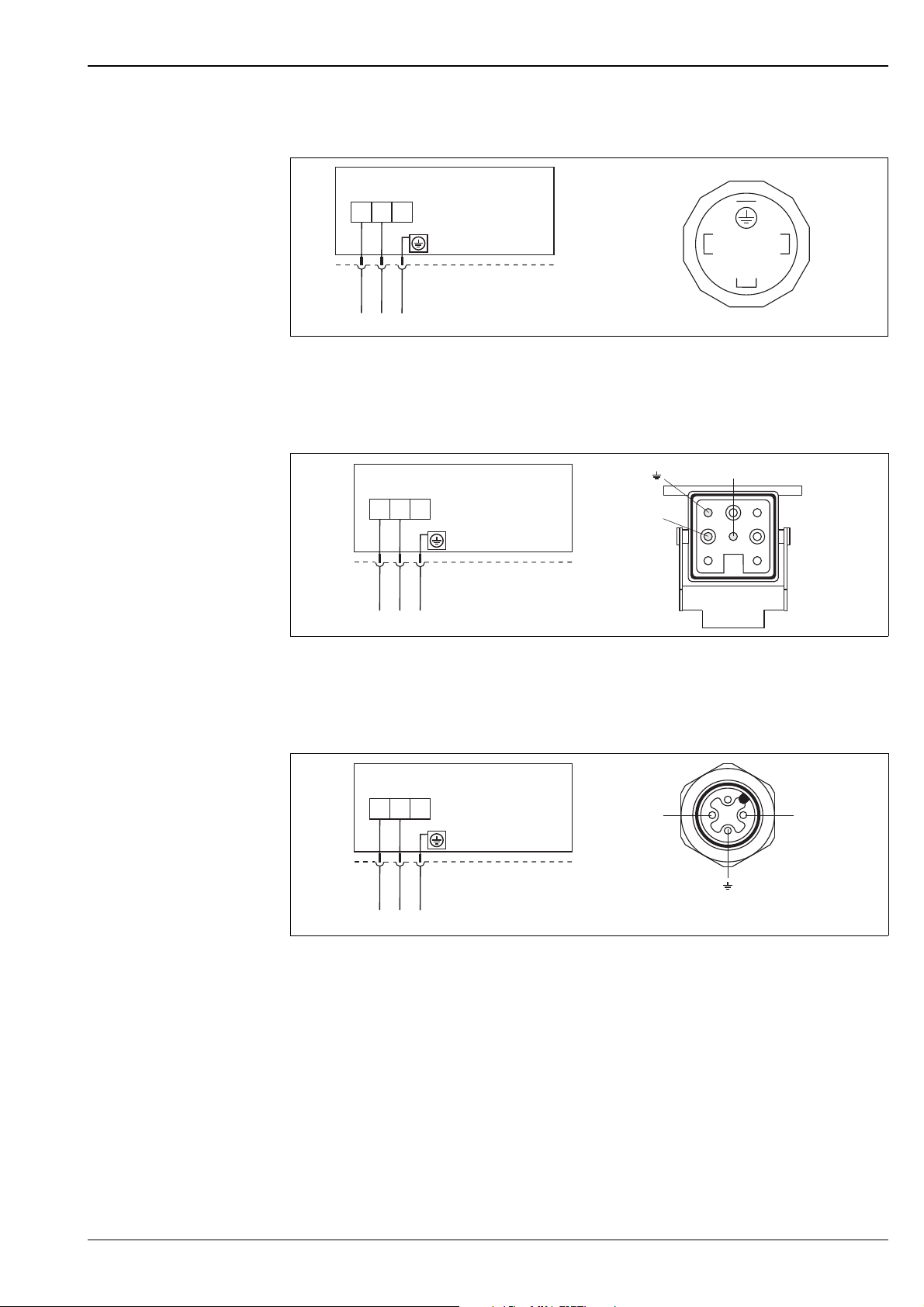
+
Devices with valve connector
Left: electrical connection for devices with a valve connector
Right: view of the connector at the device
Devices with Harting connector Han7D
P01-xMx5xxxx-04-xx-xx-xx-005
P01-xxx7xxxx-04-xx-xx-xx-001
Left: electrical connection for devices with a Harting connector Han7D
Right: view of the connector at the device
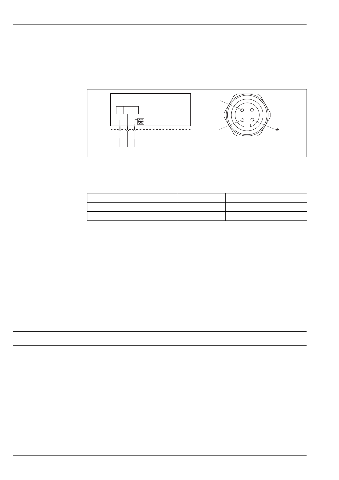
Devices with M12 connector
P01-xxx7xxxx-04-xx-xx-xx-000
Left: electrical connection for devices with an M12 connector
Right: view of the connector at the device
Endress+Hauser offers the following accessories for devices with an M12 connector:
Plug-in jack M 12x1, straight
• Material: body PA; coupling nut CuZn, nickel-plated
• Degree of protection (fully locked): IP67
• Order number: 52006263 or through device order, see also ä 63 ff "Ordering information" section
Plug-in jack M 12x1, elbowed
• Material: body PBT; coupling nut GD-Zn, nickel-plated
• Degree of protection (in screwed situation): IP67
• Order number: 71091284 or through device order, see also ä 63 ff "Ordering information" section
Endress+Hauser 13
Cerabar M PMC51, PMP51, PMP55
–
+
7/8”
–
+
+–
Cable 4x0.34 mm2 (20 AWG) with M12 socket, elbowed, screw plug, 5 m (16 ft) length
• Material: body PUR; coupling nut CuSn/Ni; cable PVC
• Degree of protection (fully locked): IP67
• Order number: 52010285 or through device order, see also ä 63 ff "Ordering information" section
Devices with 7/8" connector
P01-xxx7xxxx-04-xx-xx-xx-003
Left: electrical connection for devices with a 7/8" connector
Right: view of the connector at the device
Cable gland
Approval Type Clamping area
Standard, II1/2G Exia, IS Plastic M20x1.5 5 to 10 mm (0.2 to 0.39 in)
ATEX II1/2D, II1/2GD Exia, II3G Ex nA Metal M20x1.5 (Ex e) 7 to 10.5 mm (0.28 to 0.41 in)
Terminals
For wire cross-sections of 0.5 to 2.5 mm² (20 to 14 AWG).
Supply voltage Note!
• When using the measuring device in hazardous areas, installation must comply with the corresponding
national standards and regulations and the Safety Instructions or Installation or Control Drawings.
• All explosion protection data are given in separate documentation which is available upon request. The
Ex documentation is supplied as standard with all devices approved for use in explosion hazardous areas.
ä 77 ff, "Safety Instructions" and "Installation/Control Drawings" sections.
4 to 20 mA, 4 to 20 mA HART
• 11.5 to 45 V DC
(Versions with plug-in connection 35 V DC)
• For intrinsically safe device versions: 11.5 to 30 V DC
Cable entry ä 63 ff, feature 50 "Electrical connection".
Cable specification • Endress+Hauser recommends using twisted, shielded two-wire cables.
• Terminals for wire cross-sections 0.5 to 2.5 mm
• Cable outer diameter: 5 to 9 mm (0.2 to 0.35 in)
2
(20 to 14 AWG)
Residual ripple No influence on 4 to 20 mA signal up to 5 % residual ripple within the permitted voltage range [according to
HART hardware specification HCF_SPEC-54 (DIN IEC 60381-1)]
Influence of power supply 0.001% of URL/1 V
14 Endress+Hauser

Cerabar M PMC51, PMP51, PMP55
Performance characteristics – general
Reference operating conditions
Uncertainty of measurement for small absolute pressure ranges
Long-term stability
• As per IEC 60770
• Ambient temperature T
= constant, in the range of: +21 to +33°C (+70 to +91°F)
A
• Humidity = constant, in the range of: 5 to 80 % RH
• Ambient pressure pA = constant, in the range of: 860 to 1060 mbar (12.47 to 15.37 psi)
• Position of the measuring cell: constant, in range: 1° horizontally
• Input of LOW SENSOR TRIM and HIGH SENSOR TRIM for lower range value and upper range value
• Span based on zero point
• Material of the process isolating diaphragm PMC51: Al
(aluminum-oxide ceramic, Ceraphire®)
2O3
• Material of the process isolating diaphragm PMP51 and PMP55: AISI 316L
• Filling oil PMP51 and PMP55: silicone oil
• Supply voltage: 24 V DC ± 3 V DC
• Load with HART: 250
The smallest expanded uncertainty of measurement that can be returned by our standards is:
• 0.4% of the measured value in the range of 1 to 30 mbar
• 1% of the measured value in the range < 1 mbar.
PMC51 Long-term stability of
< 1 bar (15 psi) ±0.2 % ±0.4 % ±0.5 %
> 1 bar (15 psi) ±0.1 % ±0.25 % ±0.4 %
PMP51 Long-term stability of
< 1 bar (15 psi) ±0.2 % ±0.4 % ±0.5 %
> 1 bar to 10 bar (15 to
150 psi)
40 bar (600 psi) ±0.1 % ±0.2 % ±0.4 %
100 bar (1500 psi) ±0.1 % ±0.25 % ±0.2 %
400 bar (6000 psi) ±0.1 % ±0.25 % ±1.0 %
URL / 1 year
URL / 1 year
±0.1 % ±0.175 % ±0.4 %
Long-term stability of
URL / 5 years
Long-term stability of
URL / 5 years
Long-term stability of
URL / 10 years
Long-term stability of
URL / 10 years
1
Influence of orientation • PMC51
• PMP51
: 0.2 mbar (3 psi)
1,2
– 4 mbar (0.06 psi) for process connections with 1/2" thread and silicone oil
– 10 mbar (0.15 psi) for process connections with > thread 1/2" and flanges
1) Device rotated 180°, process connection pointing upwards.
2) This value is doubled for inert oil.
Note!
Position-dependent zero point shift can be corrected at the device. ä 19, "General installation instructions"
section and ä 60 ff, "Installation instructions" section.
Warm-up period • 4 to 20 mA analog: <1.5 s
• 4 to 20 mA HART: <5 s
Endress+Hauser 15

Cerabar M PMC51, PMP51, PMP55
Performance characteristics – ceramic process isolating diaphragm
Reference accuracy – PMC51 The reference accuracy comprises the non-linearity according to limit point setting, hysteresisand
non-reproducibility as per IEC 60770. The data refer to the calibrated span.
Gauge pressure sensors
Measuring cell Standard reference accuracy Platinum reference accuracy
100 mbar (1.5 psi)
250 mbar (4 psi), 400 mbar (6 psi),
1 bar (15 psi), 2 bar (30 psi),
4 bar (60 psi), 10 bar (150 psi)
40 bar (600 psi)
Absolute pressure sensors
Measuring cell Standard reference accuracy Platinum reference accuracy
100 mbar (1.5 psi)
250 mbar (4 psi)
400 mbar (6 psi), 1 bar (15 psi),
2 bar (30 psi), 4 bar (60 psi),
10 bar (150 psi)
40 bar (600 psi)
• TD 1:1 to TD 10:1: 0.15 %
• TD > 10:1 to TD 20:1: 0.20 %
• TD 1:1 to TD 10:1: 0.15 %
• TD > 10:1 to TD 20:1: 0.20 %
• TD 1:1 to TD 10:1: 0.15 %
• TD > 10:1 to TD 20:1: 0.20 %
• TD 1:1 to TD 10:1: 0.15 %
• TD > 10:1 to TD 13:1: 0.20 %
• TD 1:1 to TD 10:1: 0.15 %
• TD > 10:1 to TD 20:1: 0.20 %
• TD 1:1 to TD 10:1: 0.15 %
• TD > 10:1 to TD 20:1: 0.20 %
• TD 1:1 to TD 10:1: 0.15 %
• TD > 10:1 to TD 20:1: 0.20 %
•TD 1:1 to TD 10:1: ±0.075 %
• TD > 10:1 to TD 13:1: ±0.1 %
•TD 1:1 to TD 10:1: ±0.075 %
• TD > 10:1 to TD 20:1: ±0.1 %
•TD 1:1 to TD 10:1: ±0.075 %
• TD > 10:1 to TD 13:1: ±0.1 %
• TD 1:1 to TD 5:1: ±0.075 %
• ---
•TD 1:1 to TD 10:1: ±0.075 %
• TD > 10:1 to TD 13:1: ±0.1 %
•TD 1:1 to TD 10:1: ±0.075 %
• TD > 10:1 to TD 20:1: ±0.1 %
•TD 1:1 to TD 10:1: ±0.075 %
• TD > 10:1 to TD 13:1: ±0.1 %
Total performance – PMC51 The "Total performance" specification comprises the non-linearity including hysteresis, non-reproducibility as
well as the thermal change in the zero point. All specifications apply to the temperature range –10 to +60°C
(+14 to +140°F) and Turndown 1:1.
For devices with NBR or HNBR seals, the values must be multiplied by a factor of 3.
Measuring cell % URL
100 mbar (1.5 psi), 250 mbar (4 psi), 400 mbar (6 psi) TD 1:1: ±0.5
1 bar (15 psi), 2 bar (30 psi), 4 bar (60 psi), 10 bar (150 psi), 40 bar (600 psi) TD 1:1: ±0.44
Total error - PMC51 The total error comprises the long-term stability and the total performance. All specifications apply to the
temperature range –10 to +60°C (+14 to +140°F) and Turndown 1:1.
For devices with NBR or HNBR seals, the values must be multiplied by a factor of 3.
Measuring cell % URL/year
100 mbar (1.5 psi), 250 mbar (4 psi), 400 mbar (6 psi) ±0.55
1 bar (15 psi), 2 bar (30 psi), 4 bar (60 psi), 10 bar (150 psi), 40 bar (600 psi) ±0.47
Thermal change in the zero output and the output span – PMC51
Measuring cell –10 to +60 °C
(+14 to +140°F)
% of the calibrated measuring span
100 mbar (1.5 psi), 250 mbar (4 psi), 400 mbar (6 psi) (0.34 + 0.15 x TD) (0.39 + 0.25 x TD)
1 bar (15 psi), 2 bar (30 psi), 4 bar (60 psi), 10 bar
(150 psi), 40 bar (600 psi)
(0.32 + 0.1 x TD) (0.36 + 0.2 x TD)
–20 to –10 °C, +60 to +100 °C
(–4 to +14°F, +140 to +212°F)
16 Endress+Hauser

Cerabar M PMC51, PMP51, PMP55
Performance characteristics – metal process isolating diaphragm
Reference accuracy –
PMP51, PMP55
The reference accuracy comprises the non-linearity according to limit point setting, hysteresisand
non-reproducibility as per IEC 60770. The data refer to the calibrated span.
Gauge pressure sensors/absolute pressure sensors
Measuring cell Standard reference accuracy Platinum reference accuracy
400 mbar (6 psi)
1 bar (15 psi)
2 bar (30 psi)
4 bar (60 psi)
10 bar (150 psi),
40 bar (600 psi)
100 bar (1500 psi)
400 bar (6000 psi)
1) Only PMP51, PMP55 with direct diaphragm seal mounting
• TD 1:1: ±0.15 %
• TD >1:1: ±0.15 % x TD
• TD 1:1 to TD 5:1: ±0.15 %
• TD >5:1: ±0.03 % x TD
• TD 1:1 to TD 10:1: ±0.15 %
• TD >10:1 to TD 13:1: ±0.20 %
• TD 1:1 to TD 10:1: ±0.15 %
• TD >10:1 to TD 20:1: ±0.20 %
• TD 1:1 to TD 10:1: ±0.15 %
• TD >10:1 to TD 20:1: ±0.20 %
• TD 1:1 to TD 10:1: ±0.15 %
• TD >10:1 to TD 20:1: ±0.20 %
• TD 1:1 to TD 5:1: ±0.15 %
• TD >5:1: ±0.03 % x TD
• TD 1:1: ±0.15 %
• TD >1:1: ±0.15 % x TD
• TD 1:1 to TD 2.5:1: ±0.075 %
• TD >2.5:1: ±0.03 % x TD
• TD 1:1 to TD 5:1: ±0.075 %
• TD >5:1: ±0.015 % x TD
• TD 1:1 to TD 10:1: ±0.075 %
• TD > 10:1 to TD 13:1: ±0.1 %
• TD 1:1 to TD 10:1: ±0.075 %
• TD > 10:1 to TD 20:1: ±0.1 %
• TD 1:1 to TD 10:1: ±0.075 %
• TD > 10:1 to TD 13:1: ±0.1 %
• TD 1:1 to TD 5:1: ±0.15 %
• TD >5:1: ±0.03 % x TD
1)
Total performance – PMP51 The "Total performance" specification comprises the non-linearity including hysteresis, non-reproducibility as
well as the thermal change in the zero point. All specifications apply to the temperature range –10 to +60°C
(+14 to +140°F) and Turndown 1:1.
Measuring cell PMP51 PMP51 with gold/rhodium-coated
process isolating diaphragm
% of URL
400 mbar (6 psi)
1 bar (15 psi) ±0.75
2 bar (30 psi) ±0.45
4 bar (60 psi) ±0.30 ±0.3
10 bar (150 psi), 40 bar (600 psi),
100 bar (1500 psi)
400 bar (6000 psi) ±0.4 ±0.4
±0.34
±0.25 ±0.25
±1.25
Total error - PMP51 The total error comprises the long-term stability and the total performance. All specifications apply to the
temperature range –10 to +60°C (+14 to +140°F) and Turndown 1:1.
Measuring cell % of URL/year
400 mbar (6 psi) ±0.44
1 bar to 100 bar (15 psi to 1500 psi) ±0.35
400 bar (6000 psi) ±0.5
Endress+Hauser 17

Cerabar M PMC51, PMP51, PMP55
Thermal change in the zero output and the output span – PMP51 and PMP55
Note!
When using a PMP55, the influence from the respective diaphragm seal must also be taken into account
( ä 58 ff "Planning instructions for diaphragm seal systems").
PMP51 and PMP55 (basic device)
The data refer to the calibrated span.
Measuring cell –10 to +60 °C
(+14 to +140°F)
400 mbar (6 psi), 1 bar (15 psi),
2 bar (30 psi), 4 bar (60 psi), 10 bar
(150 psi), 40 bar (600 psi), 100 bar
(1500 psi)
400 bar (6000 psi) ±(0.3 + 0.35 x TD) ±(0.3 + 0.7 x TD)
±(0.34 + 0.15 x TD) ±(0.4 + 0.25 x TD)
–40 to –10°C, +60 to +85°C
(–40 to +14°F, +140 to +185°F)
18 Endress+Hauser

Cerabar M PMC51, PMP51, PMP55
Operating conditions (installation)
General installation instructions
Measuring arrangement for
devices without diaphragm
seal – PMC51, PMP51
• The position-dependent zero point shift can be corrected:
– directly at the device via operating keys on the electronic insert
– directly at the device via operating keys on the display (except analog electronics)
– via digital communication if the cover is not open (except analog electronics)
Note!
In hazardous areas, comply strictly with the safety instructions when the housing cover is closed and open.
• Endress+Hauser offers a mounting bracket for installing the device on pipes or walls.
See also ä 19, "Wall and pipe mounting" section.
• Use flushing rings for flange and cell diaphragm seals if medium buildup or clogging can be expected at the
diaphragm seal connection. The flushing ring can be inserted between the process connection and the
diaphragm seal. Thanks to the two lateral flushing bore holes, material buildup in front of the process
isolating diaphragm can be rinsed away and the pressure chamber can be ventilated.
Cerabar M transmitters without diaphragm seals are mounted as per the norms for a manometer
(DIN EN 837-2). We recommend the use of shutoff devices and siphons. The orientation depends on the
measuring application.
Pressure measurement in gases
• Mount Cerabar M with shutoff device above the tapping point so that any condensate can flow into the
process.
Pressure measurement in steams
• Mount Cerabar M with siphon below the tapping point.
• Fill the siphon with liquid before commissioning.
The siphon reduces the temperature to almost the ambient temperature.
Pressure measurement in liquids
• Mount Cerabar M with shutoff device below or at the same level as the tapping point.
Level measurement
• Mount Cerabar M below the lowest measuring point (zero point of the measurement).
• Do not mount the device at the following positions: In the filling curtain, in the tank outlet or at a point in
the container which could be affected by pressure pulses from an agitator or a pump.
• The calibration and functional test can be carried out more easily if you mount the device downstream of a
shutoff device.
Measuring arrangement for
devices with diaphragm seal
–PMP55
Wall and pipe mounting Endress+Hauser offers a mounting bracket for installing the device on pipes or walls.
• ä 58, "Planning instructions for diaphragm seal systems" section.
ä 63 ff, feature 620, "Accessory enclosed", version "PA" or as a separate accessory
(part number: 71102216).
For the dimensions, see ä 52.
Endress+Hauser 19
Cerabar M PMC51, PMP51, PMP55
➀
➁
➂
➃
r ³ 120 mm
IP xx
(see chapter
“Ordering information”)
FEP cable:
IP 69K
IP 66/68 NEMA 4/6P
PE cable:
IP 66/68 NEMA 4/6P
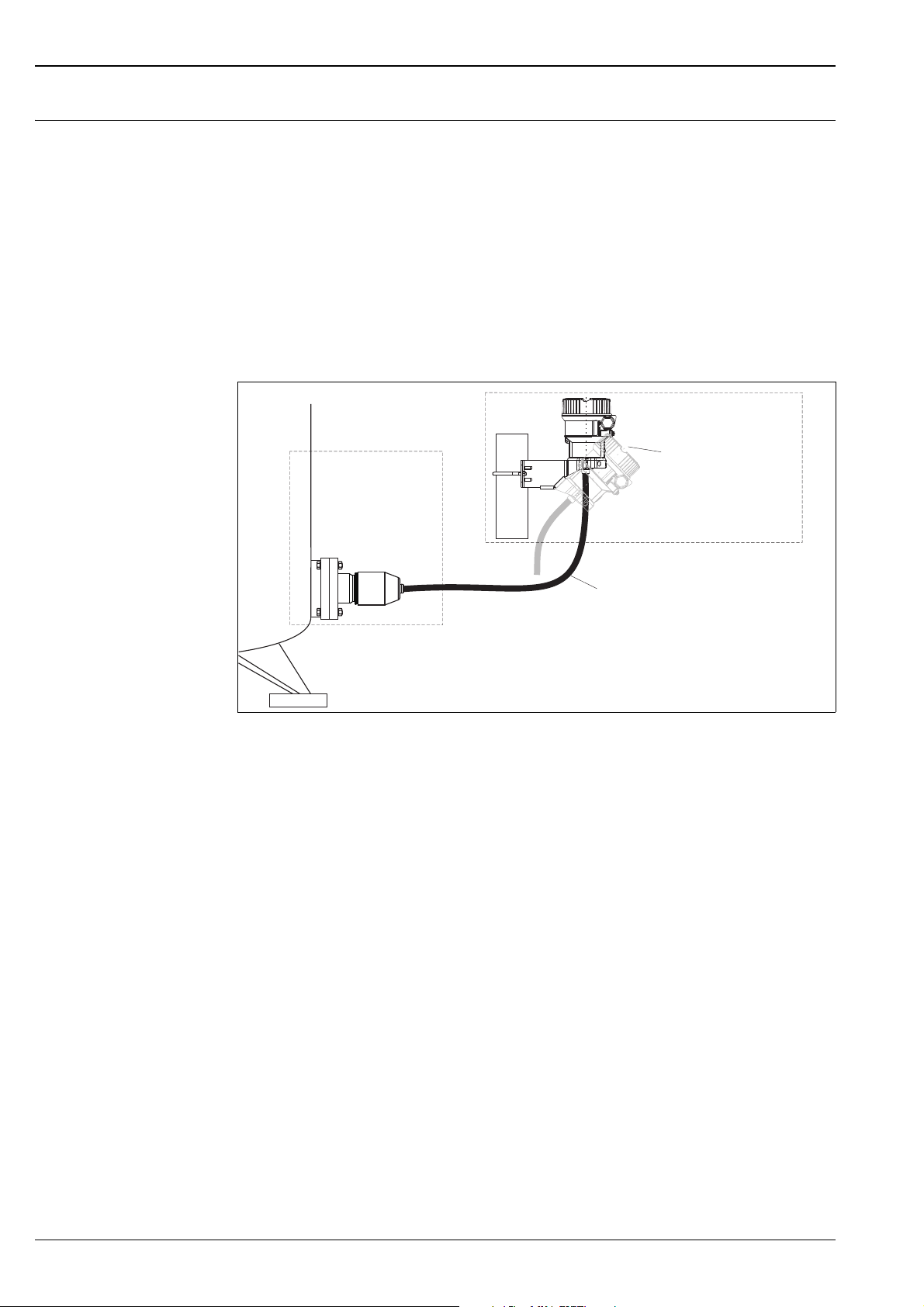
"Separate housing" version With the "separate housing" version, you are able to mount the housing with the electronics insert at a distance
from the measuring point. This version allows for trouble-free measurement:
• Under particularly difficult measuring conditions (at installation locations that are cramped or difficult to
access)
• If extreme cleaning of the measuring point is required
• If the measuring point is exposed to vibrations
• For space-saving installations
You can choose between different cable versions:
• PE (2 m (6.6 ft), 5 m (16 ft) and 10 m (33 ft))
• FEP (5 m (16 ft)).
ä 63 ff, feature 600, "Separate housing".
For the dimensions, ä 52.
P01-PMx5xxxx-11-xx-xx-en-002
In the case of the "separate housing" version, the sensor is delivered with the process connection and cable ready
mounted. The housing and a mounting bracket are enclosed as separate units. The cable is provided with a socket at both
ends. These sockets are simply connected to the housing and the sensor.
1 Process connection with sensor
2 Cable, both ends are fitted with a socket
3 Mounting bracket provided, suitable for pipe and wall mounting
4 Housing with electronic insert
Degree of protection for the process connection and sensor when using:
• FEP cable:
– IP 69K
– IP 66/68 NEMA 4/6P
• PE cable:
– IP 66/68 NEMA 4/6P
Technical data of the PE and FEP cable:
• Minimum bending radius: 120 mm (4.72 in)
• Cable extraction force: max. 450 N (101 lbf)
• Resistance to UV light
Use in hazardous area:
• Intrinsically safe installations (Ex ia/IS)
• FM/CSA IS: for Div.1 installation only
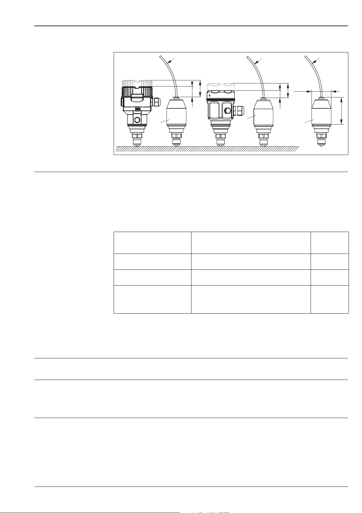
Reduction in installation height
If the separate housing is used, the mounting height of the process connection is reduced compared to the
dimensions of the standard version (see graphic).
20 Endress+Hauser
Cerabar M PMC51, PMP51, PMP55
ø54.1
29
81
F31
r ³ 120 mmr ³ 120 mm r ³ 120 mmr ³ 120 mm
➀ ➀
44
F15
r ³ 120 mmr ³ 120 mm
➀
17
36
P01-xMx5xxxx-06-xx-xx-xx-000
Oxygen applications Oxygen and other gases can react explosively to oils, grease and plastics. As a result, the following are some of
the precautions that must be taken:
– All components of the system, such as measuring devices, must be cleaned in accordance with the BAM
(DIN 19247) requirements.
– Depending on the materials used, a certain maximum temperature and maximum pressure must not be
exceeded for oxygen applications.
The devices suitable for gaseous oxygen applications are listed in the following table with the specification p
max
.
Ordering information for devices
cleaned for oxygen applications
1)
PMC51
nominal value < 10 bar (150 psi)
PMC51
nominal value 10 bar (150 psi)
PMP51 PMP55
1) Feature 570 "Service" version "HB"
2) ä 63 ff "Ordering information", feature 70 "Sensor range"
3) PMC51 with PVDF thread or PVDF flange p
– devices with sensors,
)
– devices with sensors,
)
p
for oxygen applications T
max
Over pressure limit (OPL) of sensor
40 bar (600 psi) 60°C (140°F)
Depends on the lowest-rated element, with regard to
pressure, of the selected components: over pressure limit
(OPL) of sensor
(160 bar (2320 psi))
, process connection (1.5 x PN) or fill fluid
= 15 bar (225 psi)
max
2, 3
Silicone-free applications Special cleaning of the transmitter to remove paint-wetting substances, for use in paint shops
ä 66 feature 570 "Service", version "HC".
Ultrapure gas applications Endress+Hauser also provides devices which have been cleaned of oil and grease for special applications, such
as for ultrapure gas. No special restrictions regarding the process conditions apply to these devices.
ä 63 ff, "Ordering information PMC51", feature 570 "Service" version "HA".
ä 68 ff, "Ordering information PMP51", feature 570 "Service" version "HA".
Applications with hydrogen With regard to materials in which hydrogen formation takes place, hydrogen atoms can diffuse through the
metal process isolating diaphragm. This can result in incorrect measurement results.
Endress+Hauser offers process isolating diaphragms with a gold/rhodium coating for such instances.
ä 67 ff "Ordering information PMP51" and ä 71 ff "Ordering information PMP55",
feature 170 "Membrane Material" version "M".
for
max
oxygen applications
60°C (140°F)
85°C (185°F)
Endress+Hauser 21

Operating conditions (environment)
Cerabar M PMC51, PMP51, PMP55
Ambient temperature range
Storage temperature range
Version PMC51 PMP51 PMP55
Without LCD display –40°C to +85°C (–40°F to +185°F)
With LCD display
With M12 plug , elbowed –25°C to +85°C (–13°F to +185°F)
With separate housing –20°C to +60°C (–4°F to +140°F)
Diaphragm seal systems ä 58
1) Extended temperature application range (–40°C to +85°C (–40°F to +185°F)) with restrictions in optical properties
such as display speed and contrast
1
(installation without insulation)
–20°C to +70°C (–4°F to +158°F)
Note!
For high-temperature applications, either a PMP55 with a temperature isolator or with a capillary can be used.
If vibrations also occur in the application, Endress+Hauser recommends you use a PMP55 with a capillary. If
a PMP55 with a temperature isolator or capillary is used, we recommend a suitable bracket for mounting (see
"Wall and pipe mounting" section on ä 19).
For devices for use in hazardous areas, see Safety Instructions, Installation or Control Drawing. ( ä 77 ff,
"Safety Instructions" and "Installation/Control Drawings" sections)
Version PMC51 PMP51 PMP55
Without LCD display –40°C to +90°C (–40°F to +194°F)
With LCD display –40°C to +85°C (–40°F to +185°F)
With M12 plug , elbowed –25°C to +85°C (–-13°F to +185°F)
With separate housing –40°C to +60°C (–40°F to +140°F)
Diaphragm seal systems ä 58
Degree of protection • ä 63 ff, feature 50 "Electrical connection".
• Separate housing ( ä 20)
Climate class Class 4K4H (air temperature: –20 to 55°C (–4 to +131°F), relative humidity: 4 to 100%) satisfied as per
DIN EN 60721-3-4 (condensation possible. In the case of the PMC51, condensate in the device must be
avoided.)
22 Endress+Hauser
Cerabar M PMC51, PMP51, PMP55
➀
➁
Unit to be
protected
Connection
cables
Incoming
connection cables
HAW569Z
+
-
+
-
Red
Black
+
-
Shield grounding
without
direct
➀
➁
Vibration resistance
Device/Additional
option
PMC51, PMP51, PMP55 GL VI-7-2
with mounting bracket IEC 61298-3
Test standard Vibration resistance
• Part 7: Guidelines for the Performance of Type
Approvals
• Chapter 2: Test Requirements for Electrical /
Electronic Equipment and Systems
IEC 60068-2-6
guaranteed for
3 to 18 Hz: ±4 mm (0.16 in);
25 to 500 Hz: 5 g
in all 3 planes
guaranteed for
10 to 58 Hz: ±0.15 mm (0.01 in);
58 to 500 Hz: 2 g
in all 3 planes
Note!
For high-vibration applications, either a PMC51/PMP51 with a separate housing or a PMP55 with a capillary
can be used. We recommend a suitable bracket for mounting (see "Wall and pipe mounting" section on
ä 19).
Electromagnetic compatibility • Electromagnetic compatibility as per all the relevant requirements of the EN 61326 series and NAMUR
Recommendation EMC (NE21). Details can be found in the Declaration of Conformity (in the Download
area of "www.de.endress.com", "search area - Approvals and Certificates", "Manufact. Declaration").
• Maximum deviation: < 0.5 % of span
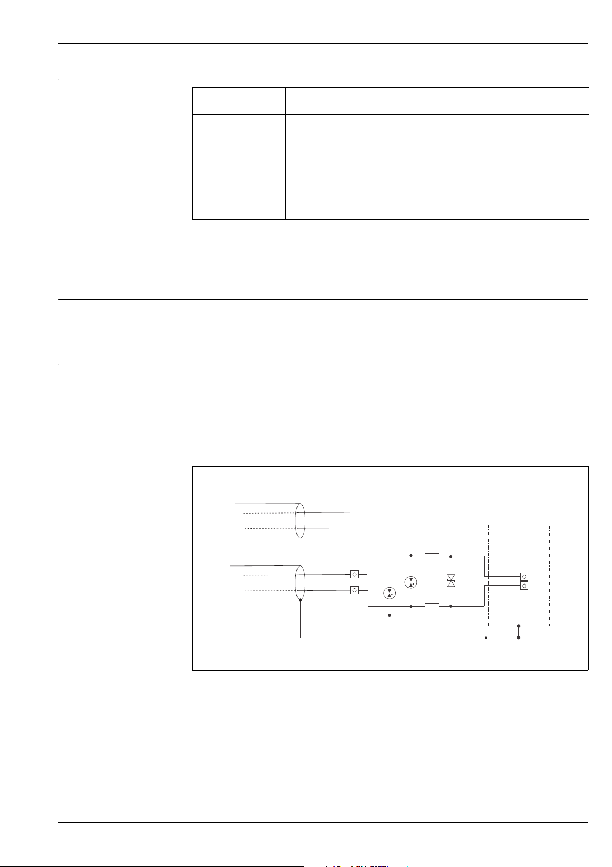
Overvoltage protection (optional)
NAThe device can be fitted with overvoltage protection, see ä 63 ff "Ordering information" feature 610
"Accessory mounted:" version "NA". The overvoltage protection is mounted at the factory on the housing
thread (M20x1.5) for the cable gland and is approx. 70 mm (2.76 in) in length (take additional length into
account when installing). The device is connected as illustrated in the following graphic.
For details refer to TI103R/09/EN, XA036R/09/A3 and KA161R/09/A6.
Wiring
P01-xMx5xxxx-04-xx-xx-en-006
Endress+Hauser 23

Operating conditions (process)
Process temperature limits PMC51 (with ceramic process isolating diaphragm)
• –20 to +100 °C (–4 to +212°F)
• Observe the process temperature range of the seal. See also the following table.
Cerabar M PMC51, PMP51, PMP55
Version for feature
190 in the order code
A FKM Viton -20 to +125°C (-4 to +257°F)
1)
A
B FKM Viton, FDA -20 to +125°C (-4 to +257°F)
F NBR -10 to +100°C (-14 to +212°F)
G HNBR, FDA, 3A Class II, KTW, AFNOR, BAM -25 to +125°C (-13 to +257°F)
J EPDM -20 to +125°C (-4 to +257°F)
K EPDM, FDA, 3A Class II, USP Class VI, DVGW, KTW,
1) With feature 570 "Service", version "HB - Cleaned for oxygen service"
Seal Process temperature range
FKM Viton, cleaned for O2 application -5 to +60°C (+23 to +140°F)
-20 to +125°C (-4 to +257°F)
W270, WRAS, ACS, NSF61
Physical limitations
Extreme jumps in temperature can result in temporary measuring errors. Temperature compensation takes
effect after several minutes. Internal temperature compensation is faster the smaller the jump in temperature
and the longer the time interval involved.
For further information please contact your local Endress+Hauser Sales Center.
PMP51 (with metal process isolating diaphragm)
Description Temperature operating range
Process connections with internal process isolating diaphragm -40 to +125°C (-40 to +257°F)
Process connections with flush-mounted process isolating
diaphragm,
G 1 A, G 1 1/2 A, G 2 A, 1 NPT, 1 1/2 NPT, 2 NPT,
M 44 x 1.25, EN/DIN, ANSI and JIS flanges
Process connections with flush-mounted process isolating
diaphragm, G 1/2 A, M 20x1.5
-40 to +100°C (-40 to +212°F)
-20 to +85°C (-4 to +185°F)
PMP55 (with diaphragm seal)
• Depending on the diaphragm seal and filling oil from -70°C (-94°F) up to +400°C (+752°F). Observe the
temperature application limits ä 58.
Note!
• Do not use diaphragm seals with 0.09 mm (0.0035 in) PTFE foil on AISI 316L for vacuum applications,
upper temperature limit +204°C (+399°F).
• For oxygen applications, observe ä 21, "Oxygen applications" section.
24 Endress+Hauser

Cerabar M PMC51, PMP51, PMP55
Pressure specifications • The maximum pressure for the measuring device depends on the lowest-rated element with regard to
pressure.
See the following sections:
– ä 7 ff, "Measuring range" section
– "Mechanical construction" section.
The MWP (maximum working pressure) is specified on the nameplate. This value refers to a reference
temperature of +20°C (68°F), or 100°F (38°C) for ANSI flanges, and may be applied to the device for an
unlimited time. Observe temperature dependency of the MWP.
• The pressure values permitted at higher temperatures can be found in the following standards:
– EN 1092-1: 2001 Tab. 18
– ASME B 16.5a – 1998 Tab. 2-2.2 F316
– ASME B 16.5a – 1998 Tab. 2.3.8 N10276
– JIS B 2220.
• The test pressure corresponds to the over pressure limit of the device (over pressure limit OPL =
1.5 x MWP
2
) and may be applied for only a limited time period in order to avoid permanent damage.
• The Pressure Equipment Directive (EC Directive 97/23/EC) uses the abbreviation "PS". The abbreviation
"PS" corresponds to the MWP (maximum working pressure) of the measuring device.
• In the case of sensor range and process connection combinations where the OPL (over pressure limit) of the
process connection is smaller than the nominal value of the sensor, the device is set at the factory, at the
very maximum, to the OPL value of the process connection. If you want to use the entire sensor range, select
a process connection with a higher OPL value (1.5 x PN; PN = MWP).
• In oxygen applications, the values for "p
applications" may not be exceeded.
1
max
and T
for oxygen applications" as per ä 21, "Oxygen
max
1) With regard to their stability-temperature property, the materials 1.4435 and 1.4404 are grouped together under 13EO
in EN 1092-1 Tab. 18. The chemical composition of the two materials can be identical.
2) The equation does not apply for PMP51 and PMP55 with a 40 bar (600 psi) - or a 100 bar (1500 psi) - measuring cell.
Endress+Hauser 25

F31 aluminum housing
115
103
94
H
➀
15
76
100
H
➀
19
G 1/2
17
20
ø11.4
ø17.5
G 1/2A 11.4 mm
ø8
ø3
ø6
G 1/2
17
20
H
3
G 1/2A
13
17
20
G 1/4
ø17.5
G 1/2
G 1/2A G 1/4
➂➁➀
H
H
dimensions
F15 stainless steel housing dimensions (hygienic)
Cerabar M PMC51, PMP51, PMP55
Mechanical construction
P01-F31xxxx-06-00-xx-xx-000
Front view, left-hand side view, top view
➀ The cover with viewing window is 15 mm (0.59 in) higher than the cover without viewing window.
For installation height H for housing with viewing window, see the specific process connection. Housing weight ä 52
P01-F15xxxx-06-00-xx-xx-000
Front view, top view.
➀ The cover with viewing window is 19 mm (0.75 in) higher than the cover without viewing window.
For installation height H for housing with viewing window, see the specific process connection. Housing weight ä 52
Process connections PMC51
Thread, internal process isolating diaphragm
(with ceramic process
isolating diaphragm)
P01-PMC71xxx-06-09-xx-xx-001
Process connections PMC51, thread ISO 228
Installation height H ä 27.
26 Endress+Hauser
1 Thread ISO 228 G 1/2 A EN 837;
Material version GCJ: AISI 316L, version GCC: Alloy C276
Version GCF: PVDF (max.: 15 bar (217.5 psi), –10 to +60 °C (+14 to +140 °F)), mount version"GCF" with a
mounting bracket only ( ä 19); weight: 0.63 kg (1.39 lbs)
2 Thread ISO 228 G 1/2 A G 1/4 (female);
Material version GLJ: AISI 316L, version GLC: Alloy C276; weight: 0.63 kg(1.39 lbs)
3 Thread ISO 228 G 1/2 A hole 11.4 mm (0.45 in);
Material version GMJ: AISI 316L, version GMC: Alloy C276; weight: 0.63 kg(1.39 lbs)
 Loading...